WO2014002587A1 - Dispositif de commande de communication, procédé de commande de communication et dispositif de communication - Google Patents
Dispositif de commande de communication, procédé de commande de communication et dispositif de communication Download PDFInfo
- Publication number
- WO2014002587A1 WO2014002587A1 PCT/JP2013/061445 JP2013061445W WO2014002587A1 WO 2014002587 A1 WO2014002587 A1 WO 2014002587A1 JP 2013061445 W JP2013061445 W JP 2013061445W WO 2014002587 A1 WO2014002587 A1 WO 2014002587A1
- Authority
- WO
- WIPO (PCT)
- Prior art keywords
- subframe
- frequency band
- communication
- primary system
- unit
- Prior art date
Links
Images


Classifications
-
- H—ELECTRICITY
- H04—ELECTRIC COMMUNICATION TECHNIQUE
- H04W—WIRELESS COMMUNICATION NETWORKS
- H04W72/00—Local resource management
- H04W72/04—Wireless resource allocation
- H04W72/044—Wireless resource allocation based on the type of the allocated resource
-
- H—ELECTRICITY
- H04—ELECTRIC COMMUNICATION TECHNIQUE
- H04L—TRANSMISSION OF DIGITAL INFORMATION, e.g. TELEGRAPHIC COMMUNICATION
- H04L12/00—Data switching networks
- H04L12/02—Details
- H04L12/16—Arrangements for providing special services to substations
- H04L12/18—Arrangements for providing special services to substations for broadcast or conference, e.g. multicast
- H04L12/1881—Arrangements for providing special services to substations for broadcast or conference, e.g. multicast with schedule organisation, e.g. priority, sequence management
-
- H—ELECTRICITY
- H04—ELECTRIC COMMUNICATION TECHNIQUE
- H04L—TRANSMISSION OF DIGITAL INFORMATION, e.g. TELEGRAPHIC COMMUNICATION
- H04L5/00—Arrangements affording multiple use of the transmission path
- H04L5/0001—Arrangements for dividing the transmission path
- H04L5/0003—Two-dimensional division
- H04L5/0005—Time-frequency
- H04L5/0007—Time-frequency the frequencies being orthogonal, e.g. OFDM(A), DMT
-
- H—ELECTRICITY
- H04—ELECTRIC COMMUNICATION TECHNIQUE
- H04L—TRANSMISSION OF DIGITAL INFORMATION, e.g. TELEGRAPHIC COMMUNICATION
- H04L5/00—Arrangements affording multiple use of the transmission path
- H04L5/003—Arrangements for allocating sub-channels of the transmission path
- H04L5/0048—Allocation of pilot signals, i.e. of signals known to the receiver
-
- H—ELECTRICITY
- H04—ELECTRIC COMMUNICATION TECHNIQUE
- H04L—TRANSMISSION OF DIGITAL INFORMATION, e.g. TELEGRAPHIC COMMUNICATION
- H04L5/00—Arrangements affording multiple use of the transmission path
- H04L5/14—Two-way operation using the same type of signal, i.e. duplex
-
- H—ELECTRICITY
- H04—ELECTRIC COMMUNICATION TECHNIQUE
- H04W—WIRELESS COMMUNICATION NETWORKS
- H04W16/00—Network planning, e.g. coverage or traffic planning tools; Network deployment, e.g. resource partitioning or cells structures
- H04W16/02—Resource partitioning among network components, e.g. reuse partitioning
- H04W16/06—Hybrid resource partitioning, e.g. channel borrowing
-
- H—ELECTRICITY
- H04—ELECTRIC COMMUNICATION TECHNIQUE
- H04W—WIRELESS COMMUNICATION NETWORKS
- H04W16/00—Network planning, e.g. coverage or traffic planning tools; Network deployment, e.g. resource partitioning or cells structures
- H04W16/14—Spectrum sharing arrangements between different networks
- H04W16/16—Spectrum sharing arrangements between different networks for PBS [Private Base Station] arrangements
-
- H—ELECTRICITY
- H04—ELECTRIC COMMUNICATION TECHNIQUE
- H04W—WIRELESS COMMUNICATION NETWORKS
- H04W72/00—Local resource management
- H04W72/20—Control channels or signalling for resource management
- H04W72/23—Control channels or signalling for resource management in the downlink direction of a wireless link, i.e. towards a terminal
-
- H—ELECTRICITY
- H04—ELECTRIC COMMUNICATION TECHNIQUE
- H04W—WIRELESS COMMUNICATION NETWORKS
- H04W72/00—Local resource management
- H04W72/30—Resource management for broadcast services
-
- H—ELECTRICITY
- H04—ELECTRIC COMMUNICATION TECHNIQUE
- H04W—WIRELESS COMMUNICATION NETWORKS
- H04W76/00—Connection management
- H04W76/10—Connection setup
- H04W76/14—Direct-mode setup
Definitions
- the present disclosure relates to a communication control device, a communication control method, and a communication device.
- LTE Long Term Evolution
- WiMAX Wireless Fidelity
- LTE-A Long Term Evolution-Advanced
- Patent Document 1 discloses a technique for supporting the sharing of communication resources between a plurality of secondary communication services.
- a wireless communication unit that wirelessly communicates with a terminal device of the primary system using a frequency band of the primary system, and a subframe that is a unit of time in wireless communication, the frequency band
- a selection unit that selects the subframe in which the frequency band can be used for a secondary system that uses the subframe secondarily, and the wireless communication unit includes identification information of the selected subframe.
- a communication control device is provided that transmits system information in the frequency band.
- a subframe that is a unit of time in wireless communication with a terminal device of the primary system using a frequency band that the primary system has, and the frequency band Selecting the subframe in which the frequency band can be used for a secondary system that uses the subband secondarily, and transmitting system information of the frequency band including identification information of the selected subframe.
- a communication control method is provided.
- a communication control device that wirelessly communicates with a terminal device of the primary system using a frequency band of the primary system is a subframe that is a unit of time in wireless communication, and the frequency band is A radio that receives system information of the frequency band including identification information of the selected subframe when the subframe that can use the frequency band is selected for a secondary system that is secondarily used.
- a communication device is provided that includes a communication unit and a control unit that causes the wireless communication unit to perform wireless communication using the frequency band within a subframe identified from the identification information.
- the primary system to efficiently notify an idle communication resource, and the secondary system can easily confirm the communication resource.
- frequency sharing within a single operator is a technology that improves the use efficiency of frequency resources by borrowing frequency resources between communication systems of different communication methods of the same operator.
- Examples of the different communication methods are W-CDMA (Wideband Code Division Multiple Access) and LTE (Long Term Evolution).
- W-CDMA Wideband Code Division Multiple Access
- LTE Long Term Evolution
- the communication capacity of the LTE network increases, and the total traffic volume in both the W-CDMA network and the LTE network can be increased. In other words, it is possible to increase the number of terminal devices that can be accommodated in both the W-CDMA network and the LTE network.
- frequency sharing between different operators is a technology that improves the use efficiency of frequency resources by borrowing frequency resources between communication systems of different operators.
- different operators for example, the operator A and the operator B
- the business operator A and the business operator B each provide an LTE wireless communication service.
- the traffic volume rapidly increases in the LTE network of the operator B and the traffic volume is low in the LTE network of the operator A
- some of the frequency resources of the LTE network of the operator A are transferred to the LTE network of the operator B.
- the communication capacity of the LTE network of the operator B increases, and the traffic volume can be increased in the LTE network of the operator B.
- frequency secondary usage that effectively utilizes frequency resources that are idle in time or space is the use of frequency resources between the primary system and the secondary system to reduce the frequency resource usage efficiency. It is a technology to improve.
- the primary system is also called a primary system.
- the secondary system is also called a secondary system.
- the primary system is the main system with priority.
- the primary system is an LTE wireless communication system.
- the secondary system is a wireless LAN system or a dedicated LTE wireless communication system including a Home eNodeB and a nearby UE (User Equipment).
- the secondary system temporarily uses the frequency resource.
- the real-time auction of the idle frequency resource is a technology for lending the idle frequency resource to an operator who wishes to use the frequency resource.
- the present disclosure focuses on secondary frequency use that effectively utilizes frequency resources that are idle in time or space.
- a technique required when this technique is applied to an LTE platform will be described.
- a resource block is a unit of scheduling in uplink and downlink.
- This resource block is a communication resource of 12 subcarriers ⁇ 7 OFDM symbols. Communication resources can thus be divided in the frequency direction and the time direction.
- User equipment can use communication resources in units of resource blocks. Also, downlink and uplink communication resources are allocated to UEs in units of resource blocks.
- not all resource blocks are used at all times. That is, when the number of UEs in the cell is small, or when the uplink or downlink traffic of the UE is small, there are idle resource blocks.
- the idle system communication resources are released by the primary system and effectively used by the secondary system, thereby improving the throughput.
- an idle communication resource unit As described above, a resource block which is a communication resource of 12 subcarriers ⁇ 7 OFDM symbols has been described as an idle communication resource.
- the resource block is a minimum unit for scheduling.
- an idle communication resource unit released to the secondary system is this resource block.
- the unit of idle communication resources released to the secondary system is a subframe. That is, communication resources of a frequency band (for example, component carrier) ⁇ 1 millisecond (ms) are released to the secondary system.
- the frequency at which communication resource release should be determined differs depending on the unit of idle communication resource to be released.
- the frequency of release determination can be very high. That is, idle communication resources can be released very dynamically. This is because, for each resource block, which UE uses the resource block can be determined, and the resource block immediately after the resource block that is in the idle state may not be in the idle state. . Therefore, the frequency of determining the release of the resource block is, for example, every 1 ms (subframe length).
- the frequency of determination of release may be lower. That is, idle communication resources can be released semi-statically.
- the frequency of determining the release of communication resources in units of subframes is, for example, every several tens of ms. In this case, for a few tens of ms, communication resources in units of subframes released in a radio frame of 10 ms are used by the secondary system.
- This disclosure focuses on the release of communication resources in units of subframes.
- the primary system is a system having a priority for using communication resources.
- the secondary system includes an idle communication resource among the communication resources of the primary system, the secondary system uses the idle communication resource under a condition that the primary system is not affected. It is. Therefore, it can be said that the primary system has a higher priority than the secondary system.
- different radio access technologies may be used for the primary system and the secondary system.
- the primary system is an LTE wireless communication system.
- the secondary system is a wireless LAN communication system as an example.
- the secondary system may be a wireless communication system including an LTE UE operating in P2P mode.
- the secondary system may be a wireless communication system including an independent small cell eNodeB (e.g., Home eNodeB, Pico eNodeB) and a UE that communicates with the eNodeB.
- eNodeB independent small cell eNodeB (e.g., Home eNodeB, Pico eNodeB) and a UE that communicates with the eNodeB.
- the priority of the primary system is high and the priority of the secondary system is low. In this case, it is unlikely that the secondary system transmits any signal to the primary system. That is, it is unlikely that the secondary system inquires of the primary system about idle communication resources. This is because such a query can increase the load on the primary system.
- the secondary system independently determines idle communication resources of the primary system without transmitting / receiving signals to / from the primary system so that the primary system is not affected. Use the determined communication resource.
- the influence of the secondary system on the primary system means that, for example, a transmission signal due to the use of communication resources of the secondary system becomes an interference source for the primary system, and the throughput of the primary system decreases. Means.
- the radio communication system is a cellular system, and therefore a cell in which the primary system is located is adjacent to another cell in the primary system.
- the transmission signal of the secondary system can be an interference source to an adjacent cell. It is desirable.
- the secondary system performs measurement of the radio wave of the primary system for a sufficiently long period, and then communication resources are not used in the primary system (that is, whether there are idle communication resources). ).
- the secondary system determines that there is a communication resource in an idle state, the secondary system uses a communication resource that seems to be in an idle state.
- FDD / TDD in LTE> frequency division duplex (FDD) and time division duplex (TDD) in the LTE wireless communication system will be described.
- FDD frequency division duplex
- TDD time division duplex
- an uplink dedicated frequency band and a downlink dedicated frequency band are used in the frequency direction.
- FDD a radio frame format including 10 subframes is used in the time direction.
- TDD the same frequency band is used for both uplink and downlink communications.
- the format of the TDD radio frame will be described more specifically with reference to FIG.
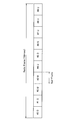
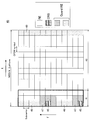
- FIG. 1 is an explanatory diagram for explaining an example of a TDD radio frame format.
- a radio frame (Radio Frame) is a unit of time in LTE, and its length is 10 ms. Further, one radio frame includes 10 subframes. A subframe is also a unit of time in LTE, and its length is 1 ms.
- the link direction for each subframe is set. For example, in the radio frame shown in FIG. 1, the downlink direction is set as the link direction of the # 0 subframe, and the uplink direction is set as the link direction of the # 3 subframe.
- the uplink is communication from the UE to the eNodeB
- the downlink is communication from the eNodeB to the UE.
- D, U, and S indicate a downlink subframe, an uplink subframe, and a special subframe, respectively.
- the special subframe will be described later.
- FDD Frequency Division Duplex
- TDD has a merit from the viewpoint of securing a frequency band.
- FDD Frequency Division Duplex
- a pair of an uplink frequency band and a downlink frequency band must be secured.
- a single frequency band may be secured.
- TDD has a merit from the viewpoint of the ratio of uplink to downlink.
- the ratio of the uplink communication resource to the downlink communication resource is one pair. 1 is fixed.
- the ratio between uplink communication resources and downlink communication resources can be changed. That is, in TDD, by changing the configuration in the link direction for each subframe in a radio frame (hereinafter referred to as “TDD configuration”), the communication resource for uplink and the communication resource for downlink are changed. It is possible to change the ratio.
- TDD is expected to increase in the future in wireless communication systems compliant with LTE or LTE-Advanced.
- TDD has the above-mentioned advantages, but it is necessary to secure time for switching between the downlink and the uplink. Therefore, in TDD, a special subframe is inserted between a downlink subframe and an uplink subframe.
- the special subframe will be described more specifically with reference to FIG.
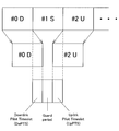
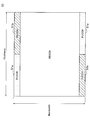
- FIG. 2 is an explanatory diagram for explaining an example of a special subframe included in a TDD radio frame.
- subframes # 0 to # 2 of the radio frame shown in FIG. 1 are shown.
- the subframe # 0 is a downlink subframe
- the subframe # 1 is a special subframe
- the subframe # 2 is an uplink subframe.
- the time for the UE to receive the downlink signal of the # 0 subframe is delayed from the time of the # 0 subframe in the format due to propagation delay in space and processing delay in the UE. To do.
- the special subframe is defined as an area for earning a delay time for the downlink and an advance time for the uplink. That is, the special subframe includes a downlink pilot time slot (DwPTS) and an uplink pilot time slot (UpPTS). In addition, the special subframe further includes a guard period (Guard Period).
- DwPTS downlink pilot time slot
- UpPTS uplink pilot time slot
- Guard Period guard period
- the secondary system performs radio wave measurement of the primary system for a sufficiently long period, and determines whether communication resources are not used in the primary system (that is, whether there are idle communication resources). To do.
- the secondary system determines that there is a communication resource in an idle state, the secondary system uses a communication resource that seems to be in an idle state.
- the communication resources that are actually idle are unknown to the secondary system. More specifically, the method of determining the communication resource in the idle state by measuring the secondary system involves a risk that the communication of the primary system starts immediately after the determination, and thus the communication resource that is actually in the idle state. Cannot be accurately identified. Furthermore, since this method requires a certain amount of time for measurement, it is not possible to specify an idle communication resource that occurs in a cycle shorter than the time required for measurement.
- the idle communication resource is notified from the primary system to the secondary system.
- the notification method a method of notifying the secondary system of idle communication resources using the LTE wireless access of the primary system is conceivable. This is because the method of notifying the secondary system via the core network (and the Internet) from the eNodeB of the primary system takes a considerable amount of time, and it is considered that the idle communication resources cannot be efficiently released. is there.
- the burden on the primary system may increase, and confirmation of idle communication resources may be difficult for the secondary system.
- the embodiment of the present disclosure enables the primary system to efficiently notify the idle communication resource and allows the secondary system to easily confirm the communication resource.
- ⁇ 2.1 Schematic Configuration of Primary System and Secondary System >>, ⁇ 3.
- First Embodiment >>, ⁇ 4.
- Second embodiment >> and ⁇ 5.
- the third embodiment >>, the specific contents will be described.
- FIG. 3 is an explanatory diagram illustrating an example of a schematic configuration of the primary system and the secondary system according to the embodiment of the present disclosure.
- a primary system including eNodeB 100 and UE 200 and a secondary system including Home eNodeB 300 and UE 400 are illustrated.
- the primary system and the secondary system are LTE or LTE-A wireless communication systems as an example.
- the primary system includes, for example, the eNodeB 100 and the UE 200.
- the eNodeB 100 performs radio communication with the UE 200 using the frequency band of the primary system in the cell 10 of the primary system.
- the frequency band is a component carrier (CC).
- the CC has a maximum bandwidth of 20 MHz.
- the eNodeB 100 performs radio communication with the UE 200 for each unit of time in radio communication.
- the unit of time in wireless communication is a 10 ms radio frame. Further, since the radio frame includes 10 subframes, it can be said that the unit of time in the radio communication is a 1 ms subframe.
- the eNodeB 100 performs uplink and downlink scheduling in units of resource blocks. That is, the eNodeB 100 allocates uplink communication resources and downlink communication resources in units of resource blocks to the UE 200.
- the CC includes a maximum of 110 resource blocks
- the subframe includes two resource blocks. That is, the CC includes a maximum of 220 resource blocks for each subframe.
- the secondary system includes, for example, the Home eNodeB 300 and the UE 400.
- the secondary system secondarily uses the frequency band of the primary system.
- the Home eNodeB 300 communicates with the UE 400 using idle communication resources that are not used in the primary system.
- idle communication resources in units of subframes are used by the secondary system. That is, the Home eNodeB 300 communicates with the UE 400 using the CC in a subframe in which the primary system does not use the CC.
- the primary system selects a subframe whose frequency band is available to the secondary system. Then, the primary system transmits system information including identification information of the selected subframe. That is, the primary system transmits identification information of a subframe whose frequency band is available for the secondary system as part of the system information.
- a method for transmitting control information by an eNodeB as a method for transmitting control information by an eNodeB, a first transmission method for transmitting control information on the PDCCH, a second transmission method for transmitting control information by RRC signaling on the PDSCH, and control information
- a third transmission method for transmitting as part of the system information can be considered.
- the PDCCH is a channel for transmitting information related to control of each resource block. For this reason, if quasi-static information indicating which subframe communication resources are to be released is transmitted on the PDCCH, communication resources are wasted.
- the secondary system cannot easily check available communication resources.
- the communication device of the secondary system is connected in the state of RRC_Connected in the primary system through synchronization in the frequency band and several control processes in RACH (Random Access Channel). It is necessary to Therefore, reception of information by RRC signaling is difficult or inconvenient for the secondary system.
- the third transmission method there is no waste of communication resources as in the first transmission method. That is, since the system information is transmitted for each frequency band, it is suitable for transmission of quasi-static information indicating which subframe communication resources are released (that is, in which subframe the frequency band is released). Yes. Further, there is no difficulty or inconvenience for the secondary system as in the second transmission method. That is, since the system information is information that can be confirmed after synchronization in the frequency band, the secondary system can easily confirm the system information.
- the primary system transmits, as part of the system information, identification information of a subframe whose frequency band is available for the secondary system.
- the primary system sets the subframe to a predetermined type of subframe in order to release communication resources of the selected subframe.
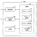
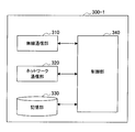
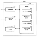
- FIG. 4 is a block diagram showing an example of the configuration of the eNodeB 100-1 of the primary system according to the first embodiment.
- the eNodeB 100-1 includes a wireless communication unit 110, a network communication unit 120, a storage unit 130, and a control unit 140.
- the radio communication unit 110 performs radio communication with the UE 200 of the primary system using the frequency band of the primary system.
- the frequency band is a component carrier (CC) having a maximum bandwidth of 20 MHz.
- wireless communication part 110 communicates with UE200 using CC in the time direction for every unit of time in radio
- the wireless communication unit 110 selects the selected subframe.
- System information of the frequency band including frame identification information is transmitted.
- the wireless communication unit 110 transmits system information on PBCH (Physical Broadcast Channel) and PDSCH (Physical Downlink Shared Channel).
- PBCH Physical Broadcast Channel
- PDSCH Physical Downlink Shared Channel
- the wireless communication unit 210 includes, for example, an antenna and an RF circuit.
- Network communication unit 120 The network communication unit 120 communicates with other communication nodes. For example, the network communication unit 120 communicates with the home eNodeB 300-1 of the secondary system directly or via any communication node.
- the storage unit 130 stores a program and data for the operation of the eNodeB 100-1.
- the storage unit 130 includes a storage medium such as a hard disk or a semiconductor memory.
- Control unit 140 The control unit 140 provides various functions of the eNodeB 100-1.
- the control unit 140 corresponds to a processor such as a CPU or a DSP, and provides the various functions described above by executing a program stored in the storage unit 130 or another storage medium.
- the control unit 140 includes a scheduling unit 141, a subframe selection unit 143, a subframe setting unit 145, and a system information generation unit 147.
- the scheduling unit 141 performs uplink and downlink scheduling. For example, the scheduling unit 141 performs scheduling in units of resource blocks. That is, the eNodeB 100 allocates uplink communication resources and downlink communication resources in units of resource blocks to the UE 200.
- the scheduling unit 141 when a subframe whose frequency band is available for the secondary system is selected by the subframe selection unit 143, the scheduling unit 141 performs scheduling of communication resources of the selected subframe. Do not do. That is, the scheduling unit 141 does not assign the resource block of the selected subframe to any UE 200.
- the subframe selection unit 143 selects a subframe in which the frequency band can be used for the secondary system. For example, the subframe selection unit 143 selects a subframe in which the frequency band can be used for the secondary system based on the usage state of the frequency band.
- subframe selection when FDD is employed in the primary system and an example of subframe selection when TDD is employed in the primary system will be described.
- the subframe selection unit 143 determines how many subframes of 10 subframes included in the radio frame can be released based on, for example, the usage state of the frequency band. Then, the subframe selecting unit 143 selects the determined number (or a number smaller than the determined number) of subframes from the ten subframes included in the radio frame.
- each subframe is either a downlink subframe or an uplink subframe.
- the frequency band is used in the downlink in the downlink subframe and is used in the uplink in the uplink subframe.
- the subframe selection unit 143 can release the communication resources of some downlink subframes among the downlink subframes included in the radio frame, for example, based on the usage state of the frequency band in the downlink. Determine whether. Then, the subframe selection unit 143 selects the determined number (or a number smaller than the determined number) of downlink subframes from the downlink subframes included in the radio frame.
- how many uplink subframes of the uplink subframes included in the radio frame can be released by the subframe selection unit 143 based on the usage status of the frequency band in the uplink. Determine. Then, the subframe selection unit 143 selects the determined number (or a number smaller than the determined number) of uplink subframes from among the uplink subframes included in the radio frame.
- the subframe selection unit 143 uses, as a subframe in which the frequency band is usable for the secondary system, an uplink subframe rather than a downlink subframe. Select with priority.
- the secondary system can use more communication resources than when the downlink subframe is selected. Therefore, the communication resource can be used more effectively.
- the primary system does not need to set a subframe as described later. Therefore, the load on the primary system can be reduced.
- the usage status of the frequency band includes, for example, the number of UEs connected to the frequency band, the sum of the number of UEs and the number of UEs to be connected to the frequency band, and use of communication resources in the frequency band.
- the subframe selection unit 143 generates identification information of the selected subframe.
- the identification information of a subframe is 10-bit information, and each bit of the 10 bits indicates whether or not communication resources of one subframe included in the radio frame are released. Also good.
- it may be determined in advance which subframe of the radio frame is to be released according to the number of subframes.
- the subframe identification information is information of several bits, and the number of bits may indicate the number of subframes in which communication resources are released.
- a plurality of patterns for example, seven patterns) of subframes that release communication resources among the ten subframes may be determined in advance.
- the subframe identification information may be several bits (for example, 3 bits) of information for uniquely identifying any one of the plurality of patterns.
- the subframe setting unit 145 sets the selected subframe to a predetermined type of subframe that is not used for downlink unicast transmission. For example, the subframe setting unit 145 sets the selected subframe as an MBSFN (Multicast-Broadcast Single Frequency Network) subframe. More specifically, the subframe setting unit 145 selects the target frequency band when the target frequency band is the downlink frequency band of the primary system or when the selected subframe is the downlink subframe of the primary system. The subframe to be processed is set as the MBSFN subframe. That is, when FDD is adopted in the primary system, the subframe setting unit 145 sets the selected subframe to the MBSFN subframe for the downlink frequency band.
- MBSFN Multicast-Broadcast Single Frequency Network
- the subframe setting unit 145 sets the selected downlink subframe as an MBSFN subframe. Such setting of the MBSFN subframe enables the secondary system to use more communication resources in the subframe.
- this point will be described more specifically with reference to FIG.
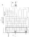
- FIG. 5 is an explanatory diagram for explaining an example of communication resources of the MBSFN subframe.
- a communication resource 40 divided into a frequency direction (f) and a time direction (t) is shown as a communication resource in the MBSFN subframe. Twelve subcarriers are shown in the frequency direction. Further, one subframe (that is, 14 OFDM symbols) is shown in the time direction. That is, 12 ⁇ 14 resource elements (RE) are shown, and two resource blocks (RB) arranged in the time direction are shown.
- the region 41 of the communication resource 40 is a region corresponding to the PDCCH in the normal subframe, and the region 43 of the communication resource 40 is a region corresponding to the PDSCH in the normal subframe.
- the UE 200 receives a CRS (Common Reference Signal) 45 in the area 41 corresponding to the PDCCH in the normal subframe.
- CRS Common Reference Signal
- the UE 200 receives the signal of the PDCCH (area 41) and the CRS of the PDSCH (area 43) even if the data addressed to itself is not received in the normal subframe.
- the subframe is set to the MBSFN subframe
- the UE 200 that is not the target of the MBSFN only needs to receive the CRS 45 of the PDCCH in the MBSFN subframe. Therefore, the subframe to be selected is set to the MBSFN subframe, and no UE 200 of the primary system is subject to MBSFN for the subframe, so that the UE 200 of the primary system allows the PDCCH (region 41) No signal other than CRS 45 is received.
- the secondary system can use communication resources excluding communication resources corresponding to the CRS 45 of the PDCCH within the selected subframe. Therefore, it is possible for the secondary system to use more communication resources compared to a technique that does not simply perform scheduling for the selected subframe.
- the setting of the subframe to the MBSFN subframe may be performed after the subframe is selected, or may be performed before the subframe is selected.
- the release of communication resources by setting the MBSFN subframe has been described, there are restrictions on the release of such communication resources. More specifically, the subframes that can be set as the MBSFN subframe are limited to specific subframes among the ten subframes included in the radio frame. Therefore, the communication resource of the specific subframe becomes a release target. For example, when FDD is adopted in the primary system, it is prohibited to set the subframes # 0, # 4, # 5, and # 9 as MBSFN subframes. Therefore, in this case, the communication resources of the subframes # 1, # 2, # 3, # 6, # 7, and # 8 are to be released. A synchronization signal is transmitted in the subframes # 0 and # 5.
- the subframe # 1 is a special subframe, which is a special subframe in which a part of the first half (variable) is transmitted.
- the selected subframe is set as an MBSFN subframe
- UE 200 subordinate to eNodeB 100-1 of the primary system ie, RRC_Connected
- the subframe is an MBSFN subframe.
- information for notifying that the selected subframe is an MBSFN subframe is included in the system information. Such notification ensures that the UE 200 does not receive a signal other than the PRSCH CRS 45 in the selected subframe.
- FIG. 6 is an explanatory diagram for describing a first example of a guard region in an MBSFN subframe.
- the area 47 around the communication resource corresponding to the CRS 45 becomes a guard area. That is, the secondary system does not use the communication resources in the guard area 47 but uses the communication resources excluding the communication resources in the guard area 47 and the communication resources corresponding to the CRS 45.
- Using such communication resources enables the UE 200 of the primary system to receive the CRS 45 with less interference.
- the frequency band within the selected subframe is a predetermined time from the start time of the subframe. It is not used by the secondary system until And / or, when the subframe immediately after the selected subframe is not selected by the subframe selection unit 143, the frequency band within the selected subframe is a predetermined time before the end time of the subframe. Until the end point.
- this point will be described more specifically with reference to FIG.
- FIG. 7 is an explanatory diagram for explaining a second example of the guard area in the MBSFN subframe.
- a region 49 corresponding to the first OFDM symbol and the 14th OFDM symbol among the OFDM symbols included in the subframe is a guard region. That is, the secondary system does not use the communication resources in the guard area 49 but uses the communication resources excluding the communication resources in the guard area 49, the communication resources in the guard area 47, and the communication resources corresponding to the CRS 45.
- FIG. 8 is an explanatory diagram for explaining an example of communication resources in a subframe for the uplink.
- uplink communication resources 50 in one subframe are shown.
- the communication resource 50 is a communication resource for one subframe of the entire frequency band.
- the regions at both ends in the frequency direction of the uplink communication resource 50 are PUCCH (Physical Uplink Control Channel) 51 which is a channel for uplink control signals.
- the PUCCH is divided into two parts (51a and 51b), and the two parts are arranged like a stack, so that both frequency diversity and time diversity effects can be obtained.
- the scheduling for the subframe is not performed (that is, the communication resource of the subframe is not allocated to the UE 200)
- the communication resource 50 does not include the PUCCH 51.
- the communication resource 50 does not include CRS. Therefore, the UE 200 of the primary system can freely use the communication resource 50.
- FIG. 9 is an explanatory diagram for explaining an example of communication resources released in a subframe for the uplink. As shown in FIG. 9, when the uplink communication resource 50 is released, the entire communication resource 50 becomes available to the secondary system.
- the communication resource 50 may include the guard area 49 as described with reference to FIG.
- the system information generation unit 147 generates system information of the frequency band that the primary system has.
- the system information includes identification information of the subframe selected by the subframe selection unit 143.
- the system information may include information for notifying that a subframe (for example, a subframe selected by the subframe selection unit 143) is an MBSFN subframe.
- FIG. 10 is a block diagram illustrating an example of the configuration of the Home eNodeB 300-1 of the secondary system according to the first embodiment.
- the eNodeB 300-1 includes a wireless communication unit 310, a network communication unit 320, a storage unit 330, and a control unit 340.
- the wireless communication unit 310 When the eNodeB 100-1 selects a subframe in which the frequency band of the primary system can be used by the secondary system, the wireless communication unit 310 identifies the identification information of the selected subframe. Including system information of the frequency band. Then, under the control of the control unit 340, the radio communication unit 310 performs radio communication with the UE 400 using the frequency band within the subframe identified from the identification information.
- the wireless communication unit 310 does not use communication resources that are close in frequency direction and time direction to the communication resources of the reference signal (for example, CRS) in the selected subframe. This is as described with reference to FIG. 6 in connection with the eNodeB 100-1.
- the reference signal for example, CRS
- the subframe immediately before the selected subframe may not be selected by the eNodeB 100-1.
- the wireless communication unit 310 does not use the frequency band in the selected subframe until a predetermined time has elapsed from the start time of the subframe.
- a subframe immediately after the selected subframe may not be selected by the eNodeB 100-1.
- the wireless communication unit 310 does not use the frequency band from a predetermined time before the end time of the subframe to the end time in the selected subframe. This is as described with reference to FIG. 7 in relation to the eNodeB 100-1.
- Network communication unit 320 The network communication unit 320 communicates with other communication nodes. For example, the network communication unit 320 communicates with the eNodeB 100-1 of the primary system directly or via any communication node.
- the storage unit 330 stores a program and data for the operation of the Home eNodeB 300-1.
- the storage unit 330 includes a storage medium such as a hard disk or a semiconductor memory.
- Control unit 340 provides various functions of the Home eNodeB 300-1.
- the control unit 340 corresponds to a processor such as a CPU or a DSP, and provides the various functions described above by executing a program stored in the storage unit 330 or another storage medium.
- control unit 340 identifies the subframe from the identification information included in the system information of the frequency band that the primary system has.
- the subframe is a subframe in which communication resources are released.
- control part 340 makes the radio
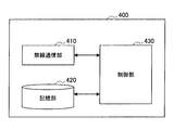
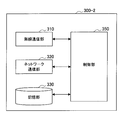
- FIG. 11 is a block diagram illustrating an example of the configuration of the UE 400 of the secondary system according to the first embodiment.
- the UE 400 includes a radio communication unit 410, a storage unit 420, and a control unit 430.
- the radio communication unit 410 uses the frequency band in the selected subframe to make the Home eNodeB 300- 1 and wireless communication.
- the wireless communication unit 410 does not use communication resources that are close to the communication resources of the reference signal (for example, CRS) in the frequency direction and the time direction in the selected subframe.
- the reference signal for example, CRS
- the subframe immediately before the selected subframe may not be selected by the eNodeB 100-1.
- the radio communication unit 410 does not use the frequency band in the selected subframe until a predetermined time has elapsed from the start time of the subframe.
- the subframe immediately after the selected subframe may not be selected by the eNodeB 100-1.
- the radio communication unit 410 uses the frequency band from a predetermined time before the end time of the subframe to the end time in the selected subframe. Not in.
- the storage unit 420 stores a program and data for the operation of the UE 400.
- the storage unit 420 includes a storage medium such as a hard disk or a semiconductor memory.
- Control unit 430 provides various functions of the UE 400.
- the control unit 430 corresponds to a processor such as a CPU or a DSP, and provides the various functions described above by executing a program stored in the storage unit 430 or another storage medium.
- control unit 430 causes the wireless communication unit 410 to communicate using the frequency band in a subframe identified from the identification information included in the system information in accordance with control by the Home eNodeB 300-1.
- the subframe is a subframe in which communication resources are released.
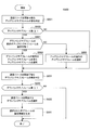
- FIG. 12 is a flowchart illustrating an example of a schematic flow of a communication control process according to the first embodiment.
- step S600 the subframe selection unit 143 executes a subframe selection process. That is, the subframe selection unit 143 selects a subframe whose frequency band is available for the secondary system.
- the subframe selection process will be described later in detail.
- step S510 the subframe selection unit determines whether there is a selected subframe. If there is a selected subframe, the process proceeds to step S700. Otherwise, the process proceeds to step S530.
- step S700 the scheduling unit 141 and the subframe setting unit 145 execute a subframe setting process.
- the subframe setting unit 145 sets the selected subframe to a predetermined type of subframe that is not used for downlink unicast transmission.
- the subframe setting process will be described in detail later.
- step S520 the system information generation unit 147 generates system information of a frequency band included in the primary system.
- the system information includes identification information of the subframe selected by the subframe selection unit 143.
- step S530 the system information generation unit 147 generates system information of a frequency band included in the primary system.
- step S540 the wireless communication unit 110 transmits system information of the frequency band of the primary system. Then, the process ends.
- FIG. 13 is a flowchart showing an example of a schematic flow of a subframe selection process (when FDD is adopted) according to the first embodiment.
- the subframe selection unit 143 determines how many subframes of 10 subframes included in the radio frame can be released based on the usage state of the frequency band.
- the usage status of the frequency band is, for example, the number of UEs that are RRC_Connected to the eNodeB, and the status of each uplink and downlink traffic of the UE in the RRC_Connected state. Then, for example, it is determined that a subframe with a small number of UEs or a small amount of traffic can be released.
- the traffic of a subframe can be transferred to another subframe, that is, other subframes other than the target subframe.
- the target traffic can be transferred and absorbed, it may be determined that the target subframe can be released. More specifically, this is a state where there is no problem even if the scheduler installed in the MAC layer of the eNodeB does not assign to the subframe.
- step S603 the subframe selection unit 143 determines whether there is one or more subframes that can release communication resources (that is, whether there are subframes that can release communication resources). If there are one or more subframes, the process proceeds to step S605. Otherwise, the process ends.
- step S605 the subframe selection unit 143 selects one or more subframes that release communication resources (that is, subframes in which a frequency band is available for the secondary system).
- step S607 the subframe selection unit 143 generates identification information of the selected subframe. Then, the process ends.
- FIG. 14 is a flowchart showing an example of a schematic flow of a subframe selection process (when TDD is adopted) according to the first embodiment.
- step S621 the subframe selection unit 143 can release the communication resources of some uplink subframes among the uplink subframes included in the radio frame based on the usage state of the frequency band in the uplink subframe. Determine whether.
- step S623 the subframe selection unit 143 determines whether there are one or more uplink subframes that can release communication resources. If there is one or more uplink subframes, the process proceeds to step S625. Otherwise, the process proceeds to step S631.
- step S625 the subframe selection unit 143 selects one or more uplink subframes that release communication resources.
- step S631 the subframe selection unit 143 can release the communication resources of some downlink subframes among the downlink subframes included in the radio frame based on the usage state of the frequency band in the downlink subframe. Determine whether.
- step S633 the subframe selection unit 143 determines whether one or more downlink subframes that can release communication resources are present. If there are one or more downlink subframes, the process proceeds to step S635. Otherwise, the process ends.
- step S635 the subframe selection unit 143 selects one or more downlink subframes that release communication resources.
- step S641 the subframe selection unit 143 generates identification information of the selected subframe (uplink subframe and downlink subframe). Then, the process ends.
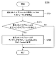
- FIG. 15 is a flowchart illustrating an example of a schematic flow of a subframe setting process according to the first embodiment.
- step S701 the scheduling unit 141 stops scheduling of the communication resource of the selected subframe (that is, does not perform scheduling).
- step S703 the subframe setting unit 145 determines whether the frequency band is a downlink frequency band (when FDD is employed) or whether the selected subframe includes a downlink subframe. If the determination is true (Yes), the process proceeds to step S705. Otherwise, the process ends.
- step S705 the subframe setting unit 145 sets the selected subframe as an MBSFN subframe.
- the primary system adopts TDD and both the downlink subframe and the uplink subframe are selected only the downlink subframe is set as the MBSFN subframe.
- the primary system is a time division duplex radio communication system. Then, the primary system sets the selected subframe as an uplink subframe. Since the subframe selected in this way is an uplink subframe, it is possible to eliminate all control signals in the subframe. Therefore, the secondary system can use more communication resources.
- the subframe setting unit 145 sets the selected subframe to a predetermined type of subframe that is not used for downlink unicast transmission.
- the subframe setting unit 145 sets the selected subframe as an uplink subframe. More specifically, for example, when the subframe already selected by the subframe selection unit 143 is a downlink subframe of the primary system, the subframe setting unit 145 selects the selected subframe as an uplink subframe. Set to frame.
- the subframe setting unit 145 sets some of the subframes included in the radio frame as uplink subframes, and the subframe selection unit 143 sets the subframes set as uplink subframes. May be selected.
- the subframe setting unit 145 changes the TDD configuration so that there are fewer downlink subframes and more uplink subframes.
- the TDD configuration may be changed such that the link direction of a specific subframe changes from the downlink to the uplink.
- FIG. 16 is a flowchart illustrating an example of a schematic flow of a subframe setting process according to a modification of the first embodiment.
- step S721 the scheduling unit 141 stops scheduling of the communication resource of the selected subframe.
- step S723 the subframe setting unit 145 determines whether the selected subframe includes a downlink subframe. If the selected subframe includes a downlink subframe, the process proceeds to step S725. Otherwise, the process ends.
- step S725 the subframe setting unit 145 changes the TDD configuration so that the selected subframe becomes an uplink subframe. That is, the subframe setting unit 145 sets the selected subframe as an uplink subframe.
- Second Embodiment >> ⁇ 4.1. Overview> Next, a second embodiment of the present disclosure will be described.
- the primary system employs FDD
- communication resources in the downlink frequency band may be released.
- the primary system employs TDD
- communication resources of the downlink subframe may be released.
- the frequency band is not used by the secondary system that performs radio communication at the cell edge of the primary system within the selected subframe.
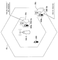
- FIG. 17 is an explanatory diagram for explaining an example of interference from the secondary system to an adjacent cell of the primary system.
- eNodeBs 100a and 100b and UEs 200a, 200b, and 200c of the primary system are shown.
- Home eNodeB 300 and UE 400 of the secondary system are shown. Note that the cell 10a of the eNodeB 100a and the cell 10b of the eNodeB 100b are adjacent to each other.
- the secondary system including the Home eNodeB 300 and the UE 400 performs wireless communication at the end of the cell 10.
- the primary system is a TDD wireless communication system
- the TDD configurations match between adjacent cells 10.
- the eNodeB 100a releases the communication resources of the downlink subframe to the secondary system in the cell 10a.
- the eNodeB 100a and the UE 200a of the primary system do not use the frequency band in the downlink subframe
- the Home eNodeB 300 and the UE 400 of the secondary system use the frequency band in the downlink subframe.
- one of the Home eNodeB 300 and the UE 400 transmits a signal toward the other.
- the eNodeB 100b does not release the communication resources of the subframe subframe to the secondary system in the cell 10b.
- the eNodeB 100b and the UEs 200b and 200c of the primary system use the frequency band in the downlink subframe.
- the eNodeB 100b transmits a downlink signal to the UE 200b and the UE 200c.
- a signal from one of Home eNodeB 300 and UE 400 communicating at the cell edge may interfere with a downlink signal from eNodeB 100b.
- the above-described interference may occur in the downlink frequency band.
- uplink communication resources are released in a cell having the primary system, it is possible to suppress interference to a cell adjacent to the cell. More specifically, when uplink communication resources are released, in the eNodeB 100b of the cell 10b, a signal from one of the Home eNodeB 300 and the UE 400 that communicates at the cell edge becomes an uplink signal from the UE 200b or the UE 200c. Can interfere. However, the Home eNodeB 300 or the UE 400 of the secondary system can predict the interference at the eNodeB 100b by observing the reference signal from the eNodeB 100b of the cell 10b. Therefore, in such a case, interference can be suppressed by, for example, power control in the secondary system.
- downlink communication resources are not used by the secondary system that performs radio communication at the end of the cell of the primary system.
- FIG. 18 is an explanatory diagram for explaining an example of a technique for suppressing interference from the secondary system to an adjacent cell of the primary system.
- the secondary system (Home eNodeB 300-2a, UE 400a) located in the center of the cell 10 uses uplink communication resources and downlink communication resources of the primary system.
- the secondary system (Home eNodeB 300-2b, UE 400b) located at the end of the cell 10 uses only the uplink communication resources of the primary system.
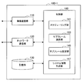
- FIG. 19 is a block diagram illustrating an example of the configuration of the eNodeB 100-2 of the primary system according to the second embodiment.
- the eNodeB 100-2 includes a wireless communication unit 111, a network communication unit 120, a storage unit 130, and a control unit 150.
- the scheduling unit 141, the subframe selection unit 143, and the subframe setting unit 145 are not different between the first embodiment and the second embodiment. Therefore, here, the wireless communication unit 111 and the system information generation unit 157 will be described.
- the radio communication unit 111 performs radio communication with the UE 200 of the primary system using the frequency band of the primary system. Further, for example, when a subframe whose frequency band is usable for the secondary system is selected by the control unit 140 (subframe selection unit 143), the wireless communication unit 111 displays the identification information of the selected subframe. Including the frequency band system information. These points are the same as those of the wireless communication unit 110 of the first embodiment.
- the target frequency band may be the downlink frequency band of the primary system, or the selected subframe may be the downlink subframe of the primary system.
- the wireless communication unit 111 transmits usage constraint information indicating that the frequency band cannot be used in the selected subframe for the secondary system that performs wireless communication at the cell edge of the primary system. Send. By transmitting such usage constraint information, it is possible to notify the secondary system that performs radio communication at the end of the primary system cell that the downlink communication resource should not be used. As a result, the frequency band can be prevented from being used by the secondary system that performs wireless communication at the cell edge of the primary system within the selected subframe. As a result, interference with adjacent cells of the primary system is suppressed.
- the wireless communication unit 111 transmits system information including the usage constraint information. That is, the usage constraint information is transmitted as part of the system information.
- the secondary system for example, Home eNodeB 300-2
- the usage constraint information can be confirmed immediately after confirmation.
- the system information generation unit 147 generates system information of the frequency band that the primary system has.
- the system information includes identification information of the subframe selected by the subframe selection unit 143.
- the system information may include information for notifying that a subframe (for example, a subframe selected by the subframe selection unit 143) is an MBSFN subframe.
- the system information generation unit 147 performs the usage constraint information.
- FIG. 20 is a block diagram illustrating an example of the configuration of the Home eNodeB 300-2 of the secondary system according to the second embodiment.
- Home eNodeB 300-2 includes a wireless communication unit 310, a network communication unit 320, a storage unit 330, and a control unit 350.
- control unit 350 will be described.
- the control unit 350 provides various functions of the Home eNodeB 300-1. For example, the control unit 350 identifies a subframe from identification information included in system information of a frequency band included in the primary system. The subframe is a subframe in which communication resources are released. And the control part 350 makes the radio
- the target frequency band may be a downlink frequency band of the primary system, or the selected subframe may be a downlink subframe of the primary system.
- the control unit 350 controls the wireless communication unit 310 so that the frequency band is not used in the selected subframe. More specifically, even if the control unit 350 acquires the identification information of the subframe, the control unit 350 uses the frequency band in the selected subframe when the usage constraint information for the subframe is also acquired. The wireless communication unit 310 is controlled so as not to occur.
- the frequency band can be prevented from being used by the secondary system that performs radio communication at the end of the cell of the primary system within the selected subframe. As a result, interference with adjacent cells of the primary system is suppressed.
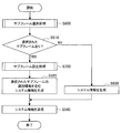
- FIG. 21 is a flowchart illustrating an example of a schematic flow of communication control processing on the eNodeB side according to the second embodiment.
- steps S550 and S560 which are differences between the example of the communication control process according to the first embodiment described with reference to FIG. 12 and the example of the communication control process according to the second embodiment, will be described. To do.
- step S550 the system information generation unit 157 determines whether the target frequency band is an uplink frequency band or whether the selected subframe includes an uplink subframe. If the determination is true (Yes), the process proceeds to step S520.
- step S560 the system information generation unit 157 generates system information including identification information and usage constraint information of the selected subframe.
- FIG. 22 is a flowchart illustrating an example of a schematic flow of communication control processing on the Home eNodeB side according to the second embodiment.
- step S810 the wireless communication unit 310 receives system information.
- step S820 control unit 350 determines whether the identification information of the subframe is included in the system information. If subframe identification information is included, the process proceeds to step S830. Otherwise, the process ends.
- step S830 the control unit 350 determines whether the Home eNodeB 300-2 is at the end of the cell 10 of the primary system. If Home eNodeB 300-2 is at the end of cell 10, the process proceeds to step S840. Otherwise, the process proceeds to step S850.
- step S840 the control unit 350 determines whether the usage constraint information is included in the system information. If usage constraint information is included, the process ends. Otherwise, the process proceeds to step S850.
- step S850 the wireless communication unit 310 performs wireless communication in a subframe identified from the identification information. Then, the process ends.
- the primary system is a TDD wireless communication system.
- the primary system prioritizes the uplink subframe immediately before the downlink subframe as the subframe in which the frequency band is usable for the secondary system, rather than the uplink subframe immediately before the uplink subframe.
- subframes in TDD are arranged according to the timing of downlink transmission and uplink reception on the eNodeB side. Therefore, in actuality, the UE receives a signal on the downlink delayed from the timing of the subframe, and transmits an uplink signal faster than the timing of the subframe.
- this point will be described more specifically with reference to FIG.
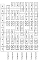
- FIG. 23 is an explanatory diagram for explaining an example of the timing of downlink reception and uplink transmission on the UE side in each TDD configuration.
- the downlink reception timing is later than the subframe timing
- the uplink transmission timing is earlier than the subframe timing.
- FIG. 23 does not show a special subframe inserted when switching from a downlink subframe to an uplink subframe.
- the special subframe is the # 1 subframe or the # 6 subframe.
- the secondary system when focusing on the uplink subframe, there is no interval between the uplink subframe and the immediately following uplink subframe, but there is a large gap between the uplink subframe and the immediately following downlink subframe. There is an interval. Therefore, when the communication resource of the uplink subframe immediately before the downlink subframe is released, the secondary system not only determines the interval between the uplink subframes but also the uplink subframe and the downlink immediately after that. Communication resources can also be used at intervals between link subframes. For example, for Configuration 0, the secondary system uses more communication resources when releasing the # 4 uplink subframe communication resources than releasing the # 8 uplink subframe communication resources. can do.
- the uplink subframe immediately before the downlink subframe is prioritized over the uplink subframe immediately before the uplink subframe. Selected.
- the secondary system can use more communication resources, and the throughput of the secondary system is improved.
- synchronization signals are transmitted in the subframes # 0, # 1, # 5, and # 6. Therefore, communication resources in subframes other than these subframes may be released.
- FIG. 24 is a block diagram illustrating an example of the configuration of the eNodeB 100-3 of the primary system according to the third embodiment.
- the eNodeB 100-3 includes a wireless communication unit 110, a network communication unit 120, a storage unit 130, and a control unit 160.
- the control unit 160 the scheduling unit 141, the subframe setting unit 145, and the system information generation unit 147 are also not different between the first embodiment and the second embodiment. Therefore, here, the subframe selection unit 163 will be described.
- the subframe selection unit 163 selects a subframe in which the frequency band can be used for the secondary system. Further, when the primary system is a TDD wireless communication system, for example, the subframe selection unit 163 uses, as a subframe in which the frequency band is usable for the secondary system, an uplink subframe rather than a downlink subframe. Select with priority. Further, the subframe selection unit 163 generates identification information of the selected subframe. About these points, it is the same as that of the sub-frame selection part 143 of 1st Embodiment.
- the subframe selection unit 163 selects an uplink subframe immediately before the downlink subframe as a subframe in which the frequency band can be used for the secondary system, rather than the uplink subframe immediately before the uplink subframe. Select with priority. For example, when the TDD configuration is Configuration 0 shown in FIG. 1 and FIG. 23, the subframe selection unit 163 performs # 4 rather than # 2, # 3, # 7, and # 8 uplink subframes. And # 9 uplink subframes are preferentially selected. By selecting such an uplink subframe, the secondary system can use more communication resources.
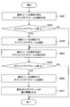
- FIG. 25 is a flowchart illustrating an example of a schematic flow of a subframe selection process according to the third embodiment.
- it is a difference between an example of the subframe selection process (when TDD is employed) according to the first embodiment described with reference to FIG. 14 and an example of the subframe selection process according to the third embodiment. Only steps S661, S663, and S665 will be described.
- step S661 the subframe selection unit 163 determines whether the uplink subframe immediately before the downlink subframe can be selected. If the uplink subframe can be selected, the process proceeds to step S663. Otherwise, the process proceeds to step S665.
- step S663 the subframe selection unit 163 selects one or more uplink subframes including the uplink subframe immediately before the downlink subframe.
- step S665 the subframe selection unit 163 selects one or more uplink subframes immediately before the downlink subframe.
- the eNodeB 100 of the primary system selects a subframe in which the frequency band is available for the secondary system. Then, the eNodeB 100 of the primary system transmits the system information of the frequency band including the identification information of the selected subframe. As a result, the primary system can effectively notify the idle communication resource, and the secondary system can easily confirm the communication resource.
- the eNodeB 100 of the primary system sets the selected subframe to a predetermined type of subframe that is not used for downlink unicast transmission. Such a setting enables the secondary system to use more communication resources in the subframe.
- the eNodeB 100 of the primary system sets the selected subframe as an MBSFN subframe.
- the UE 200 of the primary system does not receive signals other than the CRS 45 of the PDCCH (area 41) within the subframe.
- the secondary system can use communication resources excluding communication resources corresponding to the CRS 45 of the PDCCH within the selected subframe. Therefore, the secondary system can use more communication resources as compared with the method that does not perform scheduling for the selected subframe.
- the eNodeB 100 of the primary system sets the selected subframe as an uplink subframe. Since the subframe selected in this way is an uplink subframe, it is possible to eliminate all control signals in the subframe. Therefore, the secondary system can use more communication resources.
- the eNodeB 100 of the primary system is an uplink subframe rather than a downlink subframe as a subframe in which the frequency band can be used for the secondary system. Select with priority.
- the secondary system can use more communication resources than when the downlink subframe is selected. Therefore, the communication resource can be used more effectively.
- the primary system does not need to set a subframe. Therefore, the load on the primary system can be reduced.
- the frequency band is within the selected subframe, It is not used by a secondary system that communicates wirelessly at the cell edge of the primary system. In this way, by limiting the communication resources that can be used by the secondary system that performs wireless communication at the cell edge, it is possible to suppress interference with adjacent cells of the primary system.
- the eNodeB 100 of the primary system uses the uplink subframe immediately before the downlink subframe as a subframe in which the frequency band is usable for the secondary system, rather than the uplink subframe immediately before the uplink subframe. Select with priority. By selecting such an uplink subframe, the secondary system can use more communication resources.
- the secondary system may be a wireless communication system including another communication device.
- the secondary system may be another wireless communication system including any base station (or access point) and any terminal device.
- the secondary system may include a plurality of terminal devices, and the plurality of terminal devices may perform direct communication with each other.
- Such direct communication is called Device to Device communication (D2D), and is attracting attention as a new cellular technology in the future.
- D2D Device to Device communication
- the Home eNodeB of the secondary system processes information such as identification information of subframes and usage constraint information from the primary system
- the technology according to the present disclosure is not limited thereto.
- Any communication device in the secondary system may process information such as identification information of subframes and usage constraint information.
- the UE may process the information instead of the Home eNodeB or together with the Home eNodeB.
- the usage constraint information may be transmitted by any other method, for example.
- the usage constraint information may be transmitted to a communication device (for example, Home eNodeB) of the secondary system via a network including a wired network.
- communication resources in the frequency band are released focusing on one frequency band of the primary system
- the technology according to the present disclosure is not limited to this.
- Communication resources of each of a plurality of frequency bands of the primary system may be released. In this case, for example, each process of the above-described embodiment is executed for each frequency band.
- the processing steps in the communication control processing of this specification do not necessarily have to be executed in time series in the order described in the flowchart.
- the processing steps in the communication control process may be executed in an order different from the order described in the flowchart, or may be executed in parallel.
- the example in which the subframe setting process is executed after the subframe selection process in the communication control process has been described, but the communication control process according to the present disclosure is not limited thereto.
- the subframe selection process may be executed after the subframe setting process, or the individual steps included in the subframe selection process and the individual steps included in the subframe setting process are: They may be executed in any suitable order.
- the communication control device of the primary system such as eNodeB
- the hardware such as CPU, ROM and RAM incorporated in the communication device of the secondary system such as Home eNodeB and UE
- a storage medium storing the computer program is also provided.
- a wireless communication unit that wirelessly communicates with a terminal device of the primary system using a frequency band of the primary system; A subframe that is a unit of time in wireless communication, and a selection unit that selects the subframe in which the frequency band is usable for a secondary system that secondarily uses the frequency band; With The wireless communication unit transmits system information of the frequency band including identification information of the selected subframe.
- Communication control device (2) The communication control device according to (1), further comprising: a setting unit that sets the selected subframe to a predetermined type of subframe that is not used for downlink unicast transmission. . (3) The communication control apparatus according to (2), wherein the setting unit sets the selected subframe as an MBSFN subframe.
- the primary system is a time division duplex wireless communication system, The communication control apparatus according to (2), wherein the setting unit sets the selected subframe as an uplink subframe.
- the primary system is a time division duplex wireless communication system,
- the selection unit preferentially selects an uplink subframe over a downlink subframe as the subframe in which the frequency band is usable for the secondary system. Any one of (1) to (4),
- the communication resource close to the reference signal communication resource in the frequency direction and the time direction within the selected subframe is not used by the secondary system according to any one of (1) to (5). Communication control device.
- the frequency band within the selected subframe is the frequency band until the predetermined time elapses from the start time of the subframe. If the subframe immediately after the selected subframe is not used by the secondary system and is not selected by the selection unit, the frequency band within the selected subframe is the same as the end time of the subframe.
- the communication control device according to any one of (1) to (6), wherein the communication control device is not used by the secondary system from a predetermined time before the end point.
- the frequency band is a downlink frequency band of the primary system, or the selected subframe is a downlink subframe of the primary system, the frequency band is within the selected subframe.
- the communication control device according to any one of (1) to (7), wherein the communication control device is not used by a secondary system that performs radio communication at an end of a cell of the primary system.
- the wireless communication unit may be configured such that when the frequency band is a downlink frequency band of the primary system or the selected subframe is a downlink subframe of the primary system, the cell of the primary system.
- usage constraint information indicating that the frequency band is not usable in the selected subframe is transmitted to a secondary system that performs radio communication at an end of the communication system.
- the wireless communication unit includes the usage constraint information when the frequency band is a downlink frequency band of the primary system or the selected subframe is a downlink subframe of the primary system.
- the communication control device wherein the system information is transmitted.
- the primary system is a time division duplex wireless communication system,
- the selection unit prioritizes an uplink subframe immediately before a downlink subframe as an uplink subframe immediately before an uplink subframe as the subframe in which the frequency band is usable for the secondary system.
- the communication control apparatus according to any one of (1) to (10).
- a communication control device that wirelessly communicates with a terminal device of the primary system using a frequency band of the primary system is a subframe that is a unit of time in wireless communication, and uses the frequency band secondarily.
- a radio communication unit that receives system information of the frequency band including identification information of the selected subframe when the subframe in which the frequency band is available for the secondary system is selected;
- a control unit that causes the wireless communication unit to perform wireless communication using the frequency band within a subframe identified from the identification information;
- a communication device comprising:
Landscapes
- Engineering & Computer Science (AREA)
- Signal Processing (AREA)
- Computer Networks & Wireless Communication (AREA)
- Mobile Radio Communication Systems (AREA)
Abstract
Priority Applications (9)
| Application Number | Priority Date | Filing Date | Title |
|---|---|---|---|
| EP13810373.4A EP2869618B1 (fr) | 2012-06-27 | 2013-04-18 | Système secondaire utilisant les ressources du système primaire TDD |
| CN201811012271.3A CN108901072B (zh) | 2012-06-27 | 2013-04-18 | 通信控制装置、通信控制方法以及通信装置 |
| EP17168225.5A EP3220674B1 (fr) | 2012-06-27 | 2013-04-18 | Partage de ressources entre des systèmes de télécommunication |
| CN201380032653.1A CN104380778B (zh) | 2012-06-27 | 2013-04-18 | 通信控制装置、通信控制方法以及通信装置 |
| US14/409,577 US9681437B2 (en) | 2012-06-27 | 2013-04-18 | Methods and apparatus for communicating resource information in a communication system |
| EP19184968.6A EP3579600B1 (fr) | 2012-06-27 | 2013-04-18 | Dispositif de communication, procédé de commande de communication et système de communication |
| JP2014522463A JPWO2014002587A1 (ja) | 2012-06-27 | 2013-04-18 | 通信制御装置、通信制御方法及び通信装置 |
| ES13810373.4T ES2641379T3 (es) | 2012-06-27 | 2013-04-18 | Sistema secundario que utiliza recursos de sistema primario TDD |
| US15/002,234 US9900887B2 (en) | 2012-06-27 | 2016-01-20 | Communication control device and method for communicating subframe information with a terminal device |
Applications Claiming Priority (2)
| Application Number | Priority Date | Filing Date | Title |
|---|---|---|---|
| JP2012144049 | 2012-06-27 | ||
| JP2012-144049 | 2012-06-27 |
Related Child Applications (2)
| Application Number | Title | Priority Date | Filing Date |
|---|---|---|---|
| US14/409,577 A-371-Of-International US9681437B2 (en) | 2012-06-27 | 2013-04-18 | Methods and apparatus for communicating resource information in a communication system |
| US15/002,234 Continuation US9900887B2 (en) | 2012-06-27 | 2016-01-20 | Communication control device and method for communicating subframe information with a terminal device |
Publications (1)
| Publication Number | Publication Date |
|---|---|
| WO2014002587A1 true WO2014002587A1 (fr) | 2014-01-03 |
Family
ID=49782765
Family Applications (1)
| Application Number | Title | Priority Date | Filing Date |
|---|---|---|---|
| PCT/JP2013/061445 WO2014002587A1 (fr) | 2012-06-27 | 2013-04-18 | Dispositif de commande de communication, procédé de commande de communication et dispositif de communication |
Country Status (6)
| Country | Link |
|---|---|
| US (2) | US9681437B2 (fr) |
| EP (3) | EP3579600B1 (fr) |
| JP (2) | JPWO2014002587A1 (fr) |
| CN (2) | CN104380778B (fr) |
| ES (1) | ES2641379T3 (fr) |
| WO (1) | WO2014002587A1 (fr) |
Cited By (1)
| Publication number | Priority date | Publication date | Assignee | Title |
|---|---|---|---|---|
| JP2017517175A (ja) * | 2014-04-11 | 2017-06-22 | クアルコム,インコーポレイテッド | 免許不要周波数帯におけるレーダー検出のためのサブフレームの適応的使用 |
Families Citing this family (8)
| Publication number | Priority date | Publication date | Assignee | Title |
|---|---|---|---|---|
| JP5796448B2 (ja) | 2011-10-07 | 2015-10-21 | ソニー株式会社 | 無線通信装置及び無線通信方法、並びに無線通信システム |
| IN2014DN09181A (fr) | 2012-05-10 | 2015-07-10 | Sony Corp | |
| JP6065005B2 (ja) | 2012-06-05 | 2017-01-25 | ソニー株式会社 | 通信制御装置、基地局、端末装置及び通信制御方法 |
| EP3396995B1 (fr) | 2012-06-27 | 2020-07-08 | Sony Corporation | Dispositif de communication, procédé de commande de communication et système de communication |
| CN104380778B (zh) | 2012-06-27 | 2018-10-09 | 索尼公司 | 通信控制装置、通信控制方法以及通信装置 |
| US9825751B2 (en) | 2012-07-05 | 2017-11-21 | Sony Corporation | Communication control device, communication control method, program, terminal device, and communication control system |
| JP6179517B2 (ja) | 2012-08-31 | 2017-08-16 | ソニー株式会社 | 通信制御装置、端末装置、通信制御方法、プログラム及び通信制御システム |
| JP6183148B2 (ja) * | 2013-10-24 | 2017-08-23 | 富士通株式会社 | 通信端末装置、通信制御システムおよび通信制御方法 |
Citations (4)
| Publication number | Priority date | Publication date | Assignee | Title |
|---|---|---|---|---|
| WO2011136334A1 (fr) * | 2010-04-30 | 2011-11-03 | 株式会社エヌ・ティ・ティ・ドコモ | Appareil de station de base, appareil de terminal mobile et procédé de commande de communication |
| JP2012034326A (ja) | 2010-07-07 | 2012-02-16 | Sony Corp | 通信制御装置、通信制御方法、通信システム及び通信装置 |
| JP2012080509A (ja) * | 2010-10-06 | 2012-04-19 | Sumitomo Electric Ind Ltd | 管理装置、通信システム、基地局装置、及び管理方法 |
| WO2012067006A1 (fr) * | 2010-11-15 | 2012-05-24 | 株式会社エヌ・ティ・ティ・ドコモ | Station de base sans fil, terminal utilisateur et procédé de communication sans fil |
Family Cites Families (42)
| Publication number | Priority date | Publication date | Assignee | Title |
|---|---|---|---|---|
| US5125103A (en) | 1990-04-30 | 1992-06-23 | Motorola, Inc. | Automatic control channel acquisition method and apparatus in a trunked communication system |
| US7548758B2 (en) * | 2004-04-02 | 2009-06-16 | Nortel Networks Limited | System and method for peer-to-peer communication in cellular systems |
| US7519041B2 (en) | 2005-12-22 | 2009-04-14 | Motorola, Inc. | Method for improving random access channel performance |
| KR101498968B1 (ko) * | 2007-07-05 | 2015-03-12 | 삼성전자주식회사 | 통신시스템에서 피어 투 피어 통신을 위한 자원 결정 방법및 장치 |
| US8705438B2 (en) | 2007-07-10 | 2014-04-22 | Qualcomm Incorporated | Methods and apparatus for selecting and/or using a communications band for peer to peer signaling |
| KR101387529B1 (ko) * | 2007-10-15 | 2014-04-23 | 엘지전자 주식회사 | 단말의 데이터 송수신 방법, 기지국의 데이터 송수신 방법및 이동 통신 단말 |
| US8351367B2 (en) | 2008-04-24 | 2013-01-08 | Marvell World Trade Ltd. | Signaling of unused resources |
| US20090268680A1 (en) * | 2008-04-28 | 2009-10-29 | Samsung Electronics Co., Ltd. | Signaling formats for indicating unused resource blocks in lte systems |
| CN101345578B (zh) * | 2008-08-20 | 2012-09-05 | 中兴通讯股份有限公司 | 一种时分双工无线通信系统的资源调度方法 |
| JP5178915B2 (ja) | 2008-09-05 | 2013-04-10 | テレフオンアクチーボラゲット エル エム エリクソン(パブル) | セカンダリ使用のための送信の調整 |
| US8031670B2 (en) | 2008-11-13 | 2011-10-04 | Telefonaktiebolaget L M Ericsson (Publ) | Systems and methods for selecting the size of a control region of a downlink subframe |
| JP5180109B2 (ja) | 2009-01-26 | 2013-04-10 | 株式会社エヌ・ティ・ティ・ドコモ | 移動通信方法及び無線基地局 |
| CN101820584B (zh) * | 2009-02-27 | 2013-09-11 | 中兴通讯股份有限公司 | 一种资源划分及资源映射的方法和装置 |
| US8565260B2 (en) * | 2009-04-13 | 2013-10-22 | Lg Electronics Inc. | Method and apparatus for transmitting system information from a base station supporting an improved system |
| SG176761A1 (en) | 2009-06-10 | 2012-01-30 | Panasonic Corp | Radio communication terminal and radio communication method |
| JP2011071704A (ja) | 2009-09-25 | 2011-04-07 | Sony Corp | 無線通信装置、無線通信システム、および無線通信方法 |
| JP5656384B2 (ja) | 2009-10-07 | 2015-01-21 | ソニー株式会社 | 無線通信装置、信号強度出力方法及び無線通信システム |
| WO2011050519A1 (fr) * | 2009-10-28 | 2011-05-05 | Nokia Corporation | Mécanisme de suppression de brouillage dans des réseaux de communication |
| JP2011096090A (ja) | 2009-10-30 | 2011-05-12 | Sony Corp | 無線通信装置、ホスト機器への応答方法、及びプログラム |
| US20110223953A1 (en) * | 2010-03-15 | 2011-09-15 | Lg Electronics Inc. | Apparatus for direct communication in a wireless system and method thereof |
| US8811359B2 (en) | 2010-04-15 | 2014-08-19 | Qualcomm Incorporated | Multiplexing of peer-to-peer (P2P) communication and wide area network (WAN) communication |
| US9055512B2 (en) | 2010-04-15 | 2015-06-09 | Nokia Technologies Oy | Methods and apparatus for secondary bandwidth detection and allocation |
| US8750886B2 (en) * | 2010-05-06 | 2014-06-10 | Nokia Corporation | Apparatus and method for dynamic resolution of secondary communication system resources |
| US9614641B2 (en) * | 2010-05-12 | 2017-04-04 | Qualcomm Incorporated | Resource coordination for peer-to-peer groups through distributed negotiation |
| US8447315B2 (en) * | 2010-06-03 | 2013-05-21 | Nokia Corporation | Method and apparatus for facilitating device-to-device communication |
| JP5388955B2 (ja) | 2010-06-21 | 2014-01-15 | 株式会社Nttドコモ | 通信制御方法、通信システム、及び基地局装置 |
| US8964684B2 (en) | 2010-11-16 | 2015-02-24 | Lg Electronics Inc. | Method and apparatus for providing control information |
| WO2012067403A2 (fr) | 2010-11-16 | 2012-05-24 | 엘지전자 주식회사 | Procédé permettant à un terminal de transmettre une information d'interférence et à une station de base de contrôler l'interférence intercellulaire dans un système de télécommunication sans fil supportant une agrégation de porteuses, et appareil correspondant |
| KR20240037368A (ko) * | 2010-12-06 | 2024-03-21 | 인터디지탈 패튼 홀딩스, 인크 | 허가 면제 스펙트럼에서의 무선 동작을 가능케 하는 방법 |
| US8767616B2 (en) * | 2010-12-07 | 2014-07-01 | Marvell International Ltd. | Synchronized interference mitigation scheme for heterogeneous wireless networks |
| JP5796448B2 (ja) | 2011-10-07 | 2015-10-21 | ソニー株式会社 | 無線通信装置及び無線通信方法、並びに無線通信システム |
| GB2497589A (en) * | 2011-12-16 | 2013-06-19 | Renesas Mobile Corp | Resource Allocation in a Wireless Communication System |
| US8848591B2 (en) * | 2012-02-27 | 2014-09-30 | Futurewei Technologies, Inc. | System and method for message acknowledgment feedback for device-to-device communication overlaid on a cellular network |
| US9585176B2 (en) * | 2012-04-17 | 2017-02-28 | Qualcomm Incorporated | Methods and apparatus for opportunistic scheduling of peer to peer links in wide area network |
| IN2014DN09181A (fr) | 2012-05-10 | 2015-07-10 | Sony Corp | |
| US9084241B2 (en) * | 2012-05-21 | 2015-07-14 | Qualcomm Incorporated | Methods and apparatus for determining available resources for D2D communications |
| US9100941B2 (en) * | 2012-05-24 | 2015-08-04 | Nokia Solutions And Networks Oy | Using unique preambles for D2D communications in LTE |
| JP6065005B2 (ja) | 2012-06-05 | 2017-01-25 | ソニー株式会社 | 通信制御装置、基地局、端末装置及び通信制御方法 |
| CN104335624B (zh) | 2012-06-05 | 2018-03-09 | 索尼公司 | 通信控制设备、终端设备和通信控制方法 |
| CN104380778B (zh) | 2012-06-27 | 2018-10-09 | 索尼公司 | 通信控制装置、通信控制方法以及通信装置 |
| EP3396995B1 (fr) | 2012-06-27 | 2020-07-08 | Sony Corporation | Dispositif de communication, procédé de commande de communication et système de communication |
| US9825751B2 (en) | 2012-07-05 | 2017-11-21 | Sony Corporation | Communication control device, communication control method, program, terminal device, and communication control system |
-
2013
- 2013-04-18 CN CN201380032653.1A patent/CN104380778B/zh active Active
- 2013-04-18 US US14/409,577 patent/US9681437B2/en active Active
- 2013-04-18 WO PCT/JP2013/061445 patent/WO2014002587A1/fr active Application Filing
- 2013-04-18 JP JP2014522463A patent/JPWO2014002587A1/ja active Pending
- 2013-04-18 EP EP19184968.6A patent/EP3579600B1/fr active Active
- 2013-04-18 CN CN201811012271.3A patent/CN108901072B/zh active Active
- 2013-04-18 ES ES13810373.4T patent/ES2641379T3/es active Active
- 2013-04-18 EP EP17168225.5A patent/EP3220674B1/fr active Active
- 2013-04-18 EP EP13810373.4A patent/EP2869618B1/fr active Active
-
2016
- 2016-01-20 US US15/002,234 patent/US9900887B2/en active Active
-
2017
- 2017-02-03 JP JP2017018347A patent/JP6187716B2/ja active Active
Patent Citations (4)
| Publication number | Priority date | Publication date | Assignee | Title |
|---|---|---|---|---|
| WO2011136334A1 (fr) * | 2010-04-30 | 2011-11-03 | 株式会社エヌ・ティ・ティ・ドコモ | Appareil de station de base, appareil de terminal mobile et procédé de commande de communication |
| JP2012034326A (ja) | 2010-07-07 | 2012-02-16 | Sony Corp | 通信制御装置、通信制御方法、通信システム及び通信装置 |
| JP2012080509A (ja) * | 2010-10-06 | 2012-04-19 | Sumitomo Electric Ind Ltd | 管理装置、通信システム、基地局装置、及び管理方法 |
| WO2012067006A1 (fr) * | 2010-11-15 | 2012-05-24 | 株式会社エヌ・ティ・ティ・ドコモ | Station de base sans fil, terminal utilisateur et procédé de communication sans fil |
Non-Patent Citations (1)
| Title |
|---|
| See also references of EP2869618A4 |
Cited By (1)
| Publication number | Priority date | Publication date | Assignee | Title |
|---|---|---|---|---|
| JP2017517175A (ja) * | 2014-04-11 | 2017-06-22 | クアルコム,インコーポレイテッド | 免許不要周波数帯におけるレーダー検出のためのサブフレームの適応的使用 |
Also Published As
| Publication number | Publication date |
|---|---|
| US9900887B2 (en) | 2018-02-20 |
| US9681437B2 (en) | 2017-06-13 |
| EP3220674A1 (fr) | 2017-09-20 |
| CN108901072A (zh) | 2018-11-27 |
| CN104380778B (zh) | 2018-10-09 |
| JPWO2014002587A1 (ja) | 2016-05-30 |
| US20170164343A9 (en) | 2017-06-08 |
| EP3220674B1 (fr) | 2019-07-31 |
| CN108901072B (zh) | 2023-05-12 |
| EP2869618B1 (fr) | 2017-08-16 |
| ES2641379T3 (es) | 2017-11-08 |
| JP6187716B2 (ja) | 2017-08-30 |
| EP3579600B1 (fr) | 2023-03-22 |
| EP2869618A4 (fr) | 2016-02-24 |
| US20160135157A1 (en) | 2016-05-12 |
| CN104380778A (zh) | 2015-02-25 |
| EP3579600A1 (fr) | 2019-12-11 |
| JP2017103808A (ja) | 2017-06-08 |
| EP2869618A1 (fr) | 2015-05-06 |
| US20150195064A1 (en) | 2015-07-09 |
Similar Documents
| Publication | Publication Date | Title |
|---|---|---|
| JP6187716B2 (ja) | 通信装置及び通信方法 | |
| US11388720B2 (en) | Methods and apparatus for user equipment capability exchange | |
| TWI692268B (zh) | 用於車輛到車輛通訊的基於位置和先聽後排程的資源配置 | |
| JP5555246B2 (ja) | 基地局装置及びユーザ装置 | |
| EP3627920B1 (fr) | Appareil de terminal | |
| KR20210095880A (ko) | 다수의 송신-수신 포인트들을 이용한 반영구적 스케줄링 | |
| WO2017118178A1 (fr) | Procédé et dispositif d'attribution de ressource | |
| KR20190055682A (ko) | 무선 통신 시스템에서 무선 자원을 결정하기 위한 장치 및 방법 | |
| US9756482B2 (en) | Selective use of single-link communication and group communication | |
| US20170048906A1 (en) | Operation method of communication node supporting device to device communication in communication network | |
| KR102460264B1 (ko) | 통신 네트워크에서 d2d 통신을 지원하는 통신 노드의 동작 방법 | |
| WO2013166721A1 (fr) | Procédé de sélection de porteuse, et dispositif | |
| US20220295569A1 (en) | Random access channel process using single carrier waveforms | |
| EP3636019B1 (fr) | Dispositif de communication et procédé d'indication d'une préférence selon une consommation d'énergie d'un dispositif ou une performance de porteuses | |
| CN114175697A (zh) | 使用比特图的长期演进-m资源预留 | |
| CN116261873A (zh) | 副蜂窝小区群(scg)休眠期期间基于规则的波束更新 | |
| WO2021168648A1 (fr) | Hiérarchisation de puissance de transmission dans une agrégation de porteuses inter-bandes | |
| WO2022016480A1 (fr) | Configuration et commande de synchronisation de communication de liaison latérale pour des activités simultanées au niveau d'un équipement utilisateur | |
| WO2011043393A1 (fr) | Appareil de station de base et procédé de communications mobiles | |
| WO2022205035A1 (fr) | Mesure et gestion améliorées de brouillage entre liaisons | |
| US20220263614A1 (en) | Method and Devices for Wireless Communication | |
| KR20230044968A (ko) | 통신 시스템에서 자원 할당 방법 및 장치 | |
| KR20230131193A (ko) | 사용자 장비 시작 패널 상태 보고 |
Legal Events
| Date | Code | Title | Description |
|---|---|---|---|
| 121 | Ep: the epo has been informed by wipo that ep was designated in this application |
Ref document number: 13810373 Country of ref document: EP Kind code of ref document: A1 |
|
| ENP | Entry into the national phase |
Ref document number: 2014522463 Country of ref document: JP Kind code of ref document: A |
|
| REEP | Request for entry into the european phase |
Ref document number: 2013810373 Country of ref document: EP |
|
| WWE | Wipo information: entry into national phase |
Ref document number: 2013810373 Country of ref document: EP |
|
| WWE | Wipo information: entry into national phase |
Ref document number: 14409577 Country of ref document: US |
|
| NENP | Non-entry into the national phase |
Ref country code: DE |