WO2014002556A1 - 走査型内視鏡および走査型内視鏡の製造方法 - Google Patents
走査型内視鏡および走査型内視鏡の製造方法 Download PDFInfo
- Publication number
- WO2014002556A1 WO2014002556A1 PCT/JP2013/059241 JP2013059241W WO2014002556A1 WO 2014002556 A1 WO2014002556 A1 WO 2014002556A1 JP 2013059241 W JP2013059241 W JP 2013059241W WO 2014002556 A1 WO2014002556 A1 WO 2014002556A1
- Authority
- WO
- WIPO (PCT)
- Prior art keywords
- holding member
- optical fiber
- adhesive
- tip
- ferrule
- Prior art date
Links
Images


Classifications
-
- A—HUMAN NECESSITIES
- A61—MEDICAL OR VETERINARY SCIENCE; HYGIENE
- A61B—DIAGNOSIS; SURGERY; IDENTIFICATION
- A61B1/00—Instruments for performing medical examinations of the interior of cavities or tubes of the body by visual or photographical inspection, e.g. endoscopes; Illuminating arrangements therefor
- A61B1/00163—Optical arrangements
- A61B1/00172—Optical arrangements with means for scanning
-
- A—HUMAN NECESSITIES
- A61—MEDICAL OR VETERINARY SCIENCE; HYGIENE
- A61B—DIAGNOSIS; SURGERY; IDENTIFICATION
- A61B1/00—Instruments for performing medical examinations of the interior of cavities or tubes of the body by visual or photographical inspection, e.g. endoscopes; Illuminating arrangements therefor
- A61B1/00064—Constructional details of the endoscope body
- A61B1/0011—Manufacturing of endoscope parts
-
- A—HUMAN NECESSITIES
- A61—MEDICAL OR VETERINARY SCIENCE; HYGIENE
- A61B—DIAGNOSIS; SURGERY; IDENTIFICATION
- A61B1/00—Instruments for performing medical examinations of the interior of cavities or tubes of the body by visual or photographical inspection, e.g. endoscopes; Illuminating arrangements therefor
- A61B1/00163—Optical arrangements
- A61B1/00165—Optical arrangements with light-conductive means, e.g. fibre optics
-
- A—HUMAN NECESSITIES
- A61—MEDICAL OR VETERINARY SCIENCE; HYGIENE
- A61B—DIAGNOSIS; SURGERY; IDENTIFICATION
- A61B1/00—Instruments for performing medical examinations of the interior of cavities or tubes of the body by visual or photographical inspection, e.g. endoscopes; Illuminating arrangements therefor
- A61B1/06—Instruments for performing medical examinations of the interior of cavities or tubes of the body by visual or photographical inspection, e.g. endoscopes; Illuminating arrangements therefor with illuminating arrangements
- A61B1/07—Instruments for performing medical examinations of the interior of cavities or tubes of the body by visual or photographical inspection, e.g. endoscopes; Illuminating arrangements therefor with illuminating arrangements using light-conductive means, e.g. optical fibres
-
- G—PHYSICS
- G02—OPTICS
- G02B—OPTICAL ELEMENTS, SYSTEMS OR APPARATUS
- G02B21/00—Microscopes
- G02B21/0004—Microscopes specially adapted for specific applications
- G02B21/002—Scanning microscopes
- G02B21/0024—Confocal scanning microscopes (CSOMs) or confocal "macroscopes"; Accessories which are not restricted to use with CSOMs, e.g. sample holders
- G02B21/0028—Confocal scanning microscopes (CSOMs) or confocal "macroscopes"; Accessories which are not restricted to use with CSOMs, e.g. sample holders specially adapted for specific applications, e.g. for endoscopes, ophthalmoscopes, attachments to conventional microscopes
-
- G—PHYSICS
- G02—OPTICS
- G02B—OPTICAL ELEMENTS, SYSTEMS OR APPARATUS
- G02B23/00—Telescopes, e.g. binoculars; Periscopes; Instruments for viewing the inside of hollow bodies; Viewfinders; Optical aiming or sighting devices
- G02B23/24—Instruments or systems for viewing the inside of hollow bodies, e.g. fibrescopes
- G02B23/2407—Optical details
- G02B23/2423—Optical details of the distal end
-
- G—PHYSICS
- G02—OPTICS
- G02B—OPTICAL ELEMENTS, SYSTEMS OR APPARATUS
- G02B23/00—Telescopes, e.g. binoculars; Periscopes; Instruments for viewing the inside of hollow bodies; Viewfinders; Optical aiming or sighting devices
- G02B23/24—Instruments or systems for viewing the inside of hollow bodies, e.g. fibrescopes
- G02B23/2407—Optical details
- G02B23/2461—Illumination
- G02B23/2469—Illumination using optical fibres
-
- G—PHYSICS
- G02—OPTICS
- G02B—OPTICAL ELEMENTS, SYSTEMS OR APPARATUS
- G02B26/00—Optical devices or arrangements for the control of light using movable or deformable optical elements
- G02B26/08—Optical devices or arrangements for the control of light using movable or deformable optical elements for controlling the direction of light
- G02B26/10—Scanning systems
- G02B26/103—Scanning systems having movable or deformable optical fibres, light guides or waveguides as scanning elements
-
- G—PHYSICS
- G02—OPTICS
- G02B—OPTICAL ELEMENTS, SYSTEMS OR APPARATUS
- G02B23/00—Telescopes, e.g. binoculars; Periscopes; Instruments for viewing the inside of hollow bodies; Viewfinders; Optical aiming or sighting devices
- G02B23/24—Instruments or systems for viewing the inside of hollow bodies, e.g. fibrescopes
- G02B23/26—Instruments or systems for viewing the inside of hollow bodies, e.g. fibrescopes using light guides
Definitions
- the present invention relates to a scanning endoscope that scans an illumination fiber that irradiates illumination light, detects return light, and forms an image, and a method for manufacturing the scanning endoscope.
- an electronic endoscope in which an object image is photoelectrically converted by an imaging device having a solid-state imaging device such as a CCD or CMOS, and an acquired image is displayed on a monitor.
- a solid-state imaging device such as a CCD or CMOS
- the tip of an optical fiber for illumination that guides light from a light source is two-dimensionally scanned to return light from a subject.
- a scanning endoscope that receives light with a fiber bundle for light reception and forms a two-dimensional image using a light intensity signal detected over time.
- a technique for acquiring an image by scanning such an optical fiber is disclosed in, for example, an optical scanning fiber device including an endoscope described in JP Special Table 2010-513949.
- This conventional optical scanning fiber device is attached to an actuator tube like a cantilever so that one end of the optical fiber becomes a free end.
- it is desirable to bond the optical fiber so that the shape of the bonding portion of the optical fiber is a regular cone.
- the actuator is driven near the resonance frequency in order to scan the optical fiber. Since the resonance frequency at this time is greatly influenced by the length of the free end corresponding to the diameter of the optical fiber, the length of the free end of the optical fiber is kept constant in order to improve the reproducibility of the resonance frequency of the actuator. Therefore, it is necessary to have an accuracy of fixing the optical fiber to the fiber holding member provided with the actuator at the time of manufacture.
- An object of the present invention is to provide a scanning endoscope and a method for manufacturing the scanning endoscope.
- a scanning endoscope includes an optical fiber that guides light for illuminating a living body, and an insertion hole through which the optical fiber is inserted. Extending from the distal end with a predetermined length, and a holding member formed with a recess communicating with the insertion hole at the distal end, and the optical fiber provided on the holding member and extending from the distal end of the holding member A drive unit that scans the free end of the optical fiber, and an adhesive part that is applied or filled in the concave part to fix the optical fiber and the holding member, and has a flat surface that coincides with the tip of the holding member. .
- the method for manufacturing a scanning endoscope includes an optical fiber that guides light to illuminate a living body, and an insertion hole through which the optical fiber is inserted.
- a holding member having a length extending from the tip and having a recess communicating with the insertion hole at the tip, and a free end of an optical fiber provided in the holding member and extending from the tip of the holding member
- a scanning unit comprising: a driving unit that scans the optical fiber; and an adhesive part that is applied or filled in the concave part to fix the optical fiber and the holding member, and is formed with a plane that coincides with the tip of the holding member.
- the optical fiber is introduced into the insertion hole of the holding member, the optical fiber is extended from the tip of the holding member to a predetermined length, and an adhesive is applied to or filled in the recess. And the tip of the holding member To be chipped off extra said adhesive to fit a plane formed to form the adhesive portion by curing the adhesive.
- FIG. 2 is a cross-sectional view taken along line III-III in FIG.
- Sectional view of actuator according to modified example Sectional view of actuator of scanning endoscope The figure for demonstrating the example of the signal waveform supplied to an actuator similarly The figure for demonstrating the example of the scanning trace of illumination fiber similarly The graph showing the relationship between the length of the free end of the illumination fiber having a fiber diameter of 125 ⁇ m and the primary resonance frequency Same as above, a graph showing the vibration characteristics of an illumination fiber showing the relationship between drive frequency and amplitude
- a perspective view showing the configuration of the optical scanning unit The perspective view which shows the structure of the recessed part formed in the ferrule similarly The front view which shows the structure of the recessed part formed in the ferrule similarly Sectional drawing which shows the structure of the recessed part formed in the ferrule similarly The perspective view which shows the structure of the recessed part formed in the ferrule of
- FIGS. 1 is a diagram showing a configuration of a scanning endoscope apparatus having a scanning endoscope
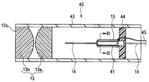
- FIG. 2 is a sectional view showing a configuration of an optical scanning unit
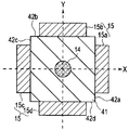
- FIG. 3 is a sectional view taken along line III-III in FIG. 4 is a sectional view of the actuator of the modified example.
- FIG. 5 is a diagram for explaining an example of a signal waveform supplied to the actuator.
- FIG. 6 is an example of a scanning locus of the illumination fiber.
- FIG. 7 is a graph showing the relationship between the length of the free end of the illumination fiber having a fiber diameter of 125 ⁇ m and the primary resonance frequency
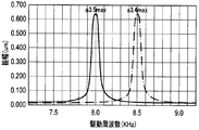
- FIG. 8 is a graph showing the vibration characteristics of the illumination fiber showing the relationship between the drive frequency and the amplitude.
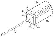
- 9 is a perspective view showing the configuration of the optical scanning unit
- FIG. 10 is a perspective view showing the configuration of a recess formed in the ferrule
- FIG. 11 is a front view showing the configuration of the recess formed in the ferrule
- FIG. 12 is a ferrule.
- FIG. 13 is a perspective view showing the configuration of a recess formed in the ferrule of the modification
- FIG. 13 is a perspective view showing the configuration of a recess formed in the ferrule of the modification
- FIG. 14 is a front view showing the configuration of the recess formed in the ferrule of the modification, and FIG. 15 is an illumination fiber.
- FIG. 16 is a cross-sectional view showing a manufacturing process in which an adhesive is applied or filled into a recess of the ferrule
- FIG. 17 is a cut off excess adhesive in accordance with the tip of the ferrule.
- FIG. 18 is a cross-sectional view showing the manufacturing process in which the adhesive has been lost due to curing
- FIG. 19 is a cross-sectional view showing the manufacturing process in which the adhesive is again applied or filled into the sinked part
- FIG. FIG. 5 is a cross-sectional view showing a manufacturing process in which excess adhesive is scraped off according to the tip of the ferrule.
- a scanning endoscope apparatus (hereinafter simply referred to as an endoscope apparatus) 1 irradiates a subject while scanning illumination light and obtains return light from the subject.
- a mirror hereinafter simply referred to as an endoscope 2
- a main body device 3 connected to the endoscope 2 and a monitor 4 that displays a subject image obtained by the main body device 3 are configured. .
- the endoscope 2 is mainly composed of a tube body having a predetermined flexibility, and has an elongated insertion portion 11 that is inserted into a living body.
- a distal end portion 12 is provided on the distal end side of the insertion portion 11.
- a proximal end side of the insertion portion 11 is provided with a connector (not shown) and the like, and the endoscope 2 is configured to be detachable from the main body device 3 through the connector and the like.
- the distal end surface 12a of the distal end portion 12 is provided with an illumination optical system 13 and a detection optical system 16a configured by illumination lenses 13a and 13b.
- the insertion unit 11 is inserted into the illumination optical system 13 from the proximal end side to the distal end side, guides light from the light source unit 24 described later, and serves as an optical element that irradiates the living body with illumination light.
- An illumination fiber 14 that is an optical fiber, and an actuator 15 that is provided on the distal end side of the illumination fiber 14 and that scans the distal end of the illumination fiber 14 in a desired direction based on a drive signal from a driver unit 25 described later are provided.
- the optical scanning unit 40 is mounted. With such a configuration, the subject is irradiated with illumination light from the light source unit 24 guided by the illumination fiber 14 of the optical scanning unit 40.
- a detection fiber 16 is provided inside the insertion portion 11 as a light receiving portion that is inserted from the proximal end side to the distal end side along the inner periphery of the insertion portion 11 and receives return light from the subject. .
- the detection optical system 16 a described above is disposed at the tip of the detection fiber 16.
- the detection fiber 16 may be a bundle of at least two fibers.
- the detection fiber 16 is connected to a duplexer 36 described later.
- a memory 17 that stores various information related to the endoscope 2 is provided inside the insertion unit 11.
- the memory 17 is connected to a controller 23 described later via a signal line (not shown), and various information related to the endoscope 2 is read by the controller 23.
- the main unit 3 includes a power source 21, a memory 22, a controller 23, a light source unit 24, a driver unit 25, and a detection unit 26.
- the light source unit 24 includes three light sources 31a, 31b, and 31c and a multiplexer 32.
- the driver unit 25 includes a signal generator 33, digital / analog (hereinafter referred to as D / A) converters 34a and 34b, and an amplifier 35.
- D / A digital / analog
- the detection unit 26 includes a duplexer 36, detectors 37a to 37c, and analog-digital (hereinafter referred to as A / D) converters 38a to 38c.
- the power supply 21 controls the supply of power to the controller 23 in accordance with an operation of a power switch (not shown).
- the memory 22 stores a control program for controlling the main device 3 as a whole.
- the controller 23 When power is supplied from the power source 21, the controller 23 reads the control program from the memory 22, controls the light source unit 24 and the driver unit 25, and the light intensity of the return light from the subject detected by the detection unit 26. Then, the periphery of the obtained subject image is masked as an image having a predetermined aspect ratio and is controlled to be displayed on the monitor 4.
- the light sources 31a, 31b, and 31c of the light source unit 24 multiplex light of different wavelength bands, for example, light of R (red), G (green), and B (blue) wavelength bands, based on the control of the controller 23.
- the light is emitted to the container 32.
- the multiplexer 32 combines the light in the R, G, and B wavelength bands emitted from the light sources 31 a, 31 b, and 31 c, and emits the light to the illumination fiber 14.
- the signal generator 33 of the driver unit 25 outputs a drive signal for scanning the tip of the illumination fiber 14 in a desired direction, for example, an elliptical spiral, based on the control of the controller 23. Specifically, the signal generator 33 outputs a drive signal for driving the tip of the illumination fiber 14 in the left-right direction (X-axis direction) with respect to the insertion axis of the insertion portion 11 to the D / A converter 34a for insertion. A drive signal for driving in the vertical direction (Y-axis direction) with respect to the insertion axis of the unit 11 is output to the D / A converter 34b.
- the D / A converters 34 a and 34 b convert the input drive signals from digital signals to analog signals and output them to the amplifier 35.
- the amplifier 35 amplifies the input drive signal and outputs it to the actuator 15.
- the actuator 15 Based on the drive signal from the amplifier 35, the actuator 15 as the vibration unit swings the tip (free end) of the illumination fiber 14 and scans it in an elliptical spiral shape. Thereby, the light emitted from the light source unit 24 to the illumination fiber 14 is sequentially irradiated to the subject in an elliptical spiral shape.
- the detection fiber 16 receives the return light reflected by the surface area of the subject, and guides the received return light to the duplexer 36.
- the demultiplexer 36 is a dichroic mirror, for example, and demultiplexes the return light in a predetermined wavelength band. Specifically, the demultiplexer 36 demultiplexes the return light guided by the detection fiber 16 into return light in the R, G, and B wavelength bands, and outputs the demultiplexed light to the detectors 37a, 37b, and 37c, respectively. .
- Detectors 37a, 37b and 37c detect the light intensity of the return light in the R, G and B wavelength bands, respectively.
- Light intensity signals detected by the detectors 37a, 37b, and 37c are output to A / D converters 38a, 38b, and 38c, respectively.
- the A / D converters 38a to 38c convert the light intensity signals output from the detectors 37a to 37c from analog signals to digital signals, respectively, and output them to the controller 23.
- the controller 23 performs predetermined image processing on the digital signals from the A / D converters 38 a to 38 c to generate a subject image and displays it on the monitor 4.
- the optical scanning unit 40 includes an illumination optical system 13 composed of illumination lenses 13a and 13b, a frame 43 that holds the illumination optical system 13, and an illumination fiber 14 that are inserted and arranged. And a holding body 44 that holds the ferrule 41 together with the actuator 15 on the frame body 43.
- a lead wire 45 extending from the driver unit 25 (see FIG. 1) is connected to the actuator 15. Note that the base end portion of the ferrule 41 is fitted to the holding body 44 so that the frame body 43 that holds the illumination optical system 13 that is the tip optical system and the ferrule 41 are integrated.
- the holding body 44 is formed with a hole through which the illumination fiber 14 and the plurality of lead wires 45 are inserted.
- a ferrule 41 as a joining member is disposed between the illumination fiber 14 and the actuator 15 as shown in FIG.
- the ferrule 41 is a member used in the field of optical communication, and is made of zirconia (ceramic), nickel or the like, and has high accuracy (for example, ⁇ 1 ⁇ m) with respect to the outer diameter (for example, 125 ⁇ m) of the illumination fiber 14.
- the center hole machining at can be easily realized.
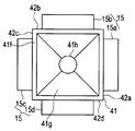
- the ferrule 41 is a quadrangular prism, and has side surfaces 42a and 42c perpendicular to the X-axis direction and side surfaces 42b and 42d perpendicular to the Y-axis direction.
- the ferrule 41 is not limited to a quadrangular prism, and may be a prism having any shape.
- a center hole processing based on the diameter of the illumination fiber 14 is performed at the approximate center of the ferrule 41, and the illumination fiber 14 is fixed with an adhesive or the like.
- the center hole processing makes the clearance (gap) as small as possible and the adhesive layer as thin as possible.
- An adhesive having a low viscosity is used.
- the actuator 15 is composed of four actuators 15a to 15d, and the actuators 15a to 15d are adjacent to the side surfaces 42a to 42d of the quadrangular prism ferrule 41, and are provided at 90 ° point symmetrical positions.
- These actuators 15a to 15d have a configuration in which electrodes are provided on two surfaces of a piezoelectric element (piezo element) that are separated from each other, and expand and contract according to a drive signal from the driver unit 25.
- the two actuators 15a and 15c as the first drive unit are driven in accordance with a drive signal from the D / A converter 34a
- the other two actuators 15b and 15d as the second drive unit are D It drives according to the drive signal from the / A converter 34b.
- the actuators 15a to 15d vibrate the ferrule 41, swing the tip of the illumination fiber 14, and scan the tip of the illumination fiber 14 in an elliptical spiral shape.
- the actuators 15a to 15d are not limited to piezoelectric vibrators configured from piezoelectric elements having a pair of electrodes, and may be, for example, coil-type vibrators that are electromagnetically driven.
- the ferrule 41 When the conductive material such as nickel is used for the ferrule 41, the ferrule 41 itself is used as the GND electrode for the GND electrodes of the actuators 15a to 15d. In addition, when a non-conductive material such as zirconia is used for the ferrule 41, the GND electrodes of the actuators 15a to 15d are processed into a conductive film on the surface of the ferrule 41 to form GND electrodes.
- the endoscope 2 is necessary for fixing the illumination fiber 14 and the ferrule 41 by inserting the ferrule 41 which is a joint member with a high-precision center hole processing between the actuator 15 and the illumination fiber 14.
- a thin adhesive layer is made as thin as possible, the influence of temperature change is reduced as much as possible, and stable driving of the illumination fiber 14 is realized.
- the actuator 15 may have a cylindrical shape.
- the illumination fiber 14 is inserted and arranged at the center of the cross section.
- An adhesive 47 is filled between the actuator 15 surrounding the illumination fiber 14 and the illumination fiber 14.
- the actuator 15 is provided with an electrode 48 on the inner peripheral surface and four electrodes 49a to 49d on the outer peripheral surface. These four electrodes 49a to 49d are arranged at a predetermined interval.
- 5A shows a signal waveform of a drive signal output from the D / A converter 34a via the amplifier 35.
- This signal waveform is a drive signal for driving the illumination fiber 14 in the X-axis direction, and is supplied to the actuators 15a and 15c.
- FIG. 5B shows the signal waveform of the drive signal output from the D / A converter 34b via the amplifier 35.
- This signal waveform is a drive signal for driving the illumination fiber 14 in the Y-axis direction, and is supplied to the actuators 15b and 15d.
- the signal waveform in the Y-axis direction is a signal waveform in which the phase of the signal waveform in the X-axis direction is shifted by 90 °.
- the phase difference between the signal waveform in the X-axis direction and the signal waveform in the Y-axis direction is as follows when the number of vibration axes N is an even number (Equation 1), and when the number of vibration axes N is an odd number. Is calculated by the following (Formula 2).
- the driver unit 25 generates the first drive signal output to the actuators 15a and 15c and the second drive signal output to the actuators 15b and 15d, and the phase of the first drive signal and the second drive signal are output.
- the control part which controls the phase difference with the phase of these drive signals based on the number N of vibration axes is comprised.
- the signal waveform gradually increases in amplitude from time T1 to time T2, and reaches a maximum amplitude value at time T2.
- the signal waveform gradually decreases in amplitude from time T2 to time T3, and becomes a minimum amplitude value at time T3.
- the scanning locus of the illumination fiber 14 at this time is the locus shown in FIG.
- the tip of the illumination fiber 14 is the position of the intersection O between the X axis and the Y axis at time T1. Then, when the amplitude of the signal waveform increases from time T1 to time T2, the tip of the illumination fiber 14 is scanned spirally outward from the intersection O, and at the time T2, for example, the position of the intersection Y1 with the Y-axis is reached. . Further, although the illustration of the tip of the illumination fiber 14 is spirally scanned inward from the intersection Y1 when the amplitude of the signal waveform decreases from the time T2 to the time T3, the position of the intersection O at the time T3 is omitted. It becomes.
- the ferrule 41 which is a joining member with a highly accurate center hole processed, is inserted between the actuator 15 and the illumination fiber 14.
- the adhesive layer necessary for fixing the illumination fiber 14 and the ferrule 41 is thinned, and the influence of the temperature change is reduced as much as possible. Therefore, this endoscope has a configuration in which the influence of temperature change is reduced and the illumination fiber can be stably driven without feedback control.
- the drive frequency of the actuator 15 is set so that the optical scanning unit 40 is driven at a predetermined resonance frequency in order to efficiently scan the illumination fiber 14.
- the resonance frequency at which it vibrates (oscillates) is determined by the fiber diameter and the length of the free end that is the amount of protrusion (extension amount) from the ferrule 41.
- the optical scanning unit 40 includes, for example, the length of the free end (from the ferrule 41) of the illumination fiber 14 having a fiber diameter (outer diameter) of 125 ⁇ m (hereinafter, description of the fiber diameter of 125 ⁇ m may be omitted).
- One resonance frequency (drive frequency) for obtaining the maximum amplitude with respect to the amount of extension) is set (assumed) from the theoretical values shown in the graph of FIG. For example, when the length of the free end of the illumination fiber 14 is set to 3.5 mm, the optical scanning unit 40 sets the drive frequency of the actuator 15 to about 8.0 KHz, so that the waveform shown in FIG. The vibration characteristic with the maximum amplitude a3.5max is obtained.
- the primary resonance frequency (drive frequency) for obtaining the maximum amplitude is about 8.5 KHz from the theoretical value shown in the graph of FIG. It is desirable to drive so as to have a vibration characteristic with the maximum amplitude a3.4max as shown in the waveform of FIG.
- the length of the free end of the illumination fiber 14 is set (assumed) to 3.5 mm and the drive frequency of the actuator 15 is set to 8.0 KHz.
- the length of the free end of 14 is, for example, ⁇ 0.1 mm with respect to the set 3.5 mm and shortened to 3.4 mm, the primary resonance frequency for obtaining the maximum amplitude a3.4max Since (driving frequency) is about 8.5 KHz, the illumination fiber 14 does not vibrate greatly.
- the resonance frequency changes by about 1.0 KHz, and the vibration characteristics vary greatly between products. That is, in the illumination fiber 14 having a fiber diameter of 125 ⁇ m, the amplitude changes according to the vibration characteristic waveform having a half-value width of about 0.1 KHz as shown in FIG.
- the vibration characteristic with the maximum amplitude is shifted by about 1.0 KHz just by shortening by 0.1 mm to 4 mm, it can be driven by the predetermined spiral scan with almost no vibration at the set (assumed) driving frequency of 8.0 KHz. Disappear.
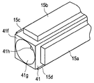
- the optical scanning unit 40 of the present embodiment is configured to fix the illumination fiber 14 by forming a recess filled with an adhesive at the tip of the ferrule 41.
- the illumination fiber 14 is fixed by an adhesive 46 as an adhesive portion having a surface portion 46a whose surface position coincides with the tip surface 41f. Yes.
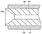
- the ferrule 41 here is conically narrowed toward the proximal end as the internal direction from the distal end surface 41f, and communicates with the fiber insertion hole 41h that has been processed into the center hole.
- Shaped recesses 41g That is, the concave portion 41g has a conical shape that opens at the distal end surface 41f of the ferrule 41 and is narrowed toward the proximal end side.
- the ferrule 41 is inserted and disposed in the fiber insertion hole 41h so that the illumination fiber 14 has a predetermined extension amount (free end of a predetermined length) from the distal end surface 41f, and covers the middle outer peripheral portion of the illumination fiber 14.
- the concave portion 41g is coated or filled with an adhesive 46 and cured.
- the adhesive 46 has a surface portion 46 a formed in the same plane as the tip surface 41 f of the ferrule 41, and fixes the illumination fiber 14 and the ferrule 41.
- the concave portion 41g formed on the distal end surface 41f of the ferrule 41 is preferably a conical shape formed so as to be narrowed toward the proximal end side, so that the adhesive 46 can be easily applied or filled without a gap.
- the present invention is not limited to this.
- the shape may be a pyramid formed so as to be narrowed toward the base end side. Any concave shape may be used.
- the assembling worker introduces the illumination fiber 14 from the proximal end of the ferrule 41 into the fiber insertion hole 41h, and guides the illumination fiber 14 from the distal end of the ferrule 41 as shown in FIG.
- the assembling worker uses a micrometer or the like to reach a position where the illumination fiber 14 has a set predetermined length L (see FIG. 16) as a specified extension amount from the distal end surface 41f of the ferrule 41. Send it out.
- the assembling worker applies or fills the adhesive 46 into the recess 41 g of the ferrule 41 without any gap so as to cover the periphery of the illumination fiber 14.
- the adhesive 46 for example, a thermosetting adhesive is used.
- the assembling worker scrapes off (cuts off) an excess portion of the adhesive 46 with a spatula or the like so that a plane in the same plane as the tip surface 41f of the ferrule 41 is formed.
- the surface portion 46a as a flat surface is formed and heat-cured to form an adhesive portion (46).
- the assembling operator applies the adhesive 46c again to the sink surface portion as shown in FIG. Fill. Then, as shown in FIG. 20, the assembling operator again scrapes off the excess portion of the adhesive 46c with a spatula or the like so that a plane in the same plane as the tip surface 41f of the ferrule 41 is formed. The part 46a is formed and heat-cured. The assembly operator repeatedly applies or fills the adhesive 46 and thermally cures until the surface 46a of the adhesive 46 forms a plane in the same plane as the tip surface 41f of the ferrule 41.
- thermosetting adhesive is used for the adhesive 46 as an adhesive portion, but the present invention is not limited to this, and an ultraviolet curable adhesive may be used.
- an ultraviolet curable adhesive may be used.
- the optical scanning unit 40 forms the recess 41g at the tip of the ferrule 41, and applies or fills the adhesive 46 that fixes the illumination fiber 14 and the ferrule 41 to the recess 41g.
- An error occurs in the length L of the free end of the illumination fiber 14 between the individual members by curing the surface 46a of the adhesive 46 so as to be a plane that matches the surface position of the tip surface 41f of the ferrule 41. Can be manufactured so that there is no.
- the scanning endoscope 2 includes the optical scanning unit 40 that eliminates the variation in the length L of the free end of the illumination fiber 14 between each individual at the time of manufacture. It can be manufactured so that the scanning characteristic of the illumination fiber between individuals is constant.
- the ferrule 41 has a quadrangular prism as an example.
- the adhesive 46 is applied to the tip surface of the cylindrical ferrule 41 shown in FIG.
- the concave portion 41g to be filled may be formed.
- this is a technique applicable to any shape of the ferrule 41.
- FIGS. 21 is an exploded perspective view showing the configuration of the optical scanning unit
- FIG. 22 is a perspective view showing the configuration of the optical scanning unit
- FIG. 23 is an exploded perspective view showing the configuration of the optical scanning unit of a modification
- FIG. 24 is a modification. It is a perspective view which shows the structure of this optical scanning unit.
- the configuration of the optical scanning unit 40 in the scanning endoscope apparatus 1 here is a modification of the first embodiment, and the above-described configuration is denoted by the same reference numeral and description thereof is omitted. To do.
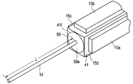
- the optical scanning unit 40 here includes an illumination fiber by a block body 50 that is a conical fixing member having substantially the same shape as the shape of the recess 41 g formed on the tip surface 41 f of the ferrule 41. 14 is assembled and fixed to the ferrule 41.
- the block body 50 has a hole portion through which the illumination fiber 14 is inserted at the center, and is fitted into the concave portion 41g of the ferrule 41 with an adhesive to fix the illumination fiber 14 and the ferrule 41. Further, as shown in FIG. 22, the block 50 has a surface portion 50 a that is in the same plane as the tip surface 41 f of the ferrule 41 in a state of being fixed to the recess 41 g of the ferrule 41.
- the block body 50 is fitted into the concave portion 41g at the tip of the ferrule 41, and the surface portion 50a of the block body 50 is aligned with the surface position of the tip surface 41f of the ferrule 41.
- the optical scanning unit 40 can be used in a state where the ferrule 41 has the free end length L of the illumination fiber 14 in a state where the optical scanning unit 40 is fitted and fixed to the recess 41 i of the ferrule 41.
- the block body 51 may have a shape having a conical tip portion 52 protruding from the tip surface 41f.
- the described requirements can be deleted if the stated problem can be solved and the stated effect can be obtained.
- the configuration can be extracted as an invention.
Abstract
走査型内視鏡2は、生体に照明する光を導光する光ファイバ14と、光ファイバ14が挿通される挿通孔41hを有して、光ファイバ14が所定の長さで先端から延設され、先端に挿通孔41hと連通する凹部41gが形成された保持部材41と、保持部材41に設けられ、保持部材41の先端から延出する光ファイバ14の自由端を走査させる駆動部15と、凹部41gに塗布または充填されて光ファイバ14と保持部材41とを固着し、保持部材41の先端と一致する平面が形成された接着部46と、を具備することで、製造時における各個体間の光ファイバの自由端の長さのバラツキをなくして、各個体間での光ファイバの走査特性が一定となる。
Description
本発明は、照明光を照射する照明ファイバを走査させて戻り光を検出して画像化する走査型内視鏡および走査型内視鏡の製造方法に関する。
周知の如く、CCD、CMOSなどの固体撮像素子を有した撮像装置により被検体像を光電変換して、モニタに取得画像を表示する電子内視鏡がある。近年、このような固体撮像素子の技術を用いず、被写体像を画像表示する装置として、光源からの光を導光する照明用の光ファイバの先端を2次元走査させ、被検体からの戻り光を受光用のファイババンドルで受光して、経時的に検出した光強度信号を用いて2次元画像化する走査型内視鏡装が知られている。
このような光ファイバを走査して画像を取得する技術は、例えば、JP特表2010-513949号公報に記載の内視鏡を含む光走査型ファイバ装置に開示されている。この従来の光走査型ファイバ装置は、光ファイバの一端が自由端となるように片持ち梁のようにアクチュエータ管体に接着して取り付けている。このとき、JP特表2010-513949号公報の光走査型ファイバ装置では、光ファイバの接着部の形状が正円錐状となるように接着することが望ましいとされている。
ところで、従来の光走査型ファイバ装置は、光ファイバを走査させるため、アクチュエータを共振周波数近傍で駆動させている。このときの共振周波数は、光ファイバの径に応じた自由端の長さにより大きく左右されるため、アクチュエータの共振周波数の再現性を高めるには、光ファイバの自由端の長さを一定に保つ必要があり、製造時に光ファイバをアクチュエータが設けられたファイバ保持部材に固着する精度が要求される。
しかしながら、外力により折れ易い光ファイバを損傷無くファイバ保持部材に接着作業しなければならない状況下で、JP特表2010-513949号公報の光走査型ファイバ装置のように微量な接着剤を塗布して正確に正円錐状となるように形成することは非常に困難である。そのため、従来の光走査型ファイバ装置では、光ファイバの自由端の長さが一定とならず、光走査ユニットの製造個体差が発生し、光ファイバの走査特性にバラツキが生じるという問題があった。
そこで、本発明は、上述の事情に鑑みてなされたもので、製造時における各個体間の光ファイバの自由端の長さのバラツキをなくして、各個体間での光ファイバの走査特性が一定となる走査型内視鏡および走査型内視鏡の製造方法を提供することを目的とする。
上記目的を達成するため、本発明の一態様の走査型内視鏡は、生体に照明する光を導光する光ファイバと、前記光ファイバが挿通される挿通孔を有して、前記光ファイバが所定の長さで先端から延設され、前記先端に前記挿通孔と連通する凹部が形成された保持部材と、前記保持部材に設けられ、前記保持部材の前記先端から延出する前記光ファイバの自由端を走査させる駆動部と、前記凹部に塗布または充填されて前記光ファイバと前記保持部材とを固着し、前記保持部材の先端と一致する平面が形成された接着部と、を具備する。
また、本発明の一態様の走査型内視鏡の製造方法は、生体に照明する光を導光する光ファイバと、前記光ファイバが挿通される挿通孔を有して、前記光ファイバが所定の長さで先端から延設され、前記先端に前記挿通孔と連通する凹部が形成された保持部材と、前記保持部材に設けられ、前記保持部材の前記先端から延出する光ファイバの自由端を走査させる駆動部と、前記凹部に塗布または充填されて前記光ファイバと前記保持部材とを固着し、前記保持部材の先端と一致する平面が形成された接着部と、を具備する走査型内視鏡の製造方法において、前記光ファイバを前記保持部材の前記挿通孔に導入し、前記光ファイバを前記保持部材の前記先端から所定の長さに延出し、前記凹部に接着剤を塗布または充填し、前記保持部材の先端面に合わせて余分な前記接着剤を削ぎ落として平面形成し、前記接着剤を硬化して前記接着部を形成する。
以下、本発明である内視鏡について説明する。なお、以下の説明において、各実施の形態に基づく図面は、模式的なものであり、各部分の厚みと幅との関係、夫々の部分の厚みの比率などは現実のものとは異なることに留意すべきであり、図面の相互間においても互いの寸法の関係や比率が異なる部分が含まれている場合がある。
(第1の実施の形態)
先ず、図1から図20を用いて、本発明の第1の実施の形態の走査型内視鏡を有する走査型内視鏡装置の構成について以下に説明する。図1は、走査型内視鏡を有する走査型内視鏡装置の構成を示す図、図2は光走査ユニットの構成を示す断面図、図3は図2のIII-III線断面図、図4は変形例のアクチュエータの断面図走査型内視鏡のアクチュエータの断面図、図5はアクチュエータに供給される信号波形の例を説明するための図、図6は照明ファイバの走査軌跡の例を説明するための図、図7はファイバ径125μmの照明ファイバ自由端の長さと1次共振周波数の関係を示すグラフ、図8は駆動周波数と振幅の関係を示した照明ファイバの振動特性を表すグラフ、図9は光走査ユニットの構成を示す斜視図、図10はフェルールに形成された凹部の構成を示す斜視図、図11はフェルールに形成された凹部の構成を示す正面図、図12はフェルールに形成された凹部の構成を示す断面図、図13は変形例のフェルールに形成された凹部の構成を示す斜視図、図14は変形例のフェルールに形成された凹部の構成を示す正面図、図15は照明ファイバをフェルールに挿通する製造過程を示す断面図、図16はフェルールの凹部に接着剤を塗布または充填した製造過程を示す断面図、図17はフェルールの先端に合わせて余分な接着剤を削ぎ落とした製造過程を示す断面図、図18は硬化により接着剤がひけた状態の製造過程を示す断面図、図19はひけた部分に再度接着剤を塗布または充填した製造過程を示す断面図、図20はフェルールの先端に合わせて余分な接着剤を削ぎ落とした製造過程を示す断面図である。
先ず、図1から図20を用いて、本発明の第1の実施の形態の走査型内視鏡を有する走査型内視鏡装置の構成について以下に説明する。図1は、走査型内視鏡を有する走査型内視鏡装置の構成を示す図、図2は光走査ユニットの構成を示す断面図、図3は図2のIII-III線断面図、図4は変形例のアクチュエータの断面図走査型内視鏡のアクチュエータの断面図、図5はアクチュエータに供給される信号波形の例を説明するための図、図6は照明ファイバの走査軌跡の例を説明するための図、図7はファイバ径125μmの照明ファイバ自由端の長さと1次共振周波数の関係を示すグラフ、図8は駆動周波数と振幅の関係を示した照明ファイバの振動特性を表すグラフ、図9は光走査ユニットの構成を示す斜視図、図10はフェルールに形成された凹部の構成を示す斜視図、図11はフェルールに形成された凹部の構成を示す正面図、図12はフェルールに形成された凹部の構成を示す断面図、図13は変形例のフェルールに形成された凹部の構成を示す斜視図、図14は変形例のフェルールに形成された凹部の構成を示す正面図、図15は照明ファイバをフェルールに挿通する製造過程を示す断面図、図16はフェルールの凹部に接着剤を塗布または充填した製造過程を示す断面図、図17はフェルールの先端に合わせて余分な接着剤を削ぎ落とした製造過程を示す断面図、図18は硬化により接着剤がひけた状態の製造過程を示す断面図、図19はひけた部分に再度接着剤を塗布または充填した製造過程を示す断面図、図20はフェルールの先端に合わせて余分な接着剤を削ぎ落とした製造過程を示す断面図である。
図1に示すように、走査型内視鏡装置(以下、単に内視鏡装置という)1は、照明光を走査させながら被検体に照射し、被検体からの戻り光を得る走査型内視鏡(以下、単に内視鏡という)2と、この内視鏡2に接続される本体装置3と、本体装置3で得られる被検体像を表示するモニタ4とを有して構成されている。
内視鏡2は、所定の可撓性を備えたチューブ体を主体として構成され、生体内に挿通される細長な挿入部11を有する。挿入部11の先端側には、先端部12が設けられている。また、挿入部11の基端側は、図示しないコネクタなどが設けられており、内視鏡2は、このコネクタなどを介して、本体装置3と着脱自在に構成されている。
先端部12の先端面12aには、照明レンズ13a,13bにより構成される照明光学系13および検出光学系16aが設けられている。また、挿入部11の内部には、照明光学系13と、基端側から先端側へ挿通され、後述する光源ユニット24からの光を導光し、生体に照明光を照射する光学素子としての光ファイバである照明ファイバ14と、照明ファイバ14の先端側に設けられ、後述するドライバユニット25からの駆動信号に基づき、照明ファイバ14の先端を所望の方向に走査させるアクチュエータ15と、が設けられた光走査ユニット40が搭載されている。このような構成により、光走査ユニット40の照明ファイバ14によって導光された光源ユニット24からの照明光が被写体に照射される。
また、挿入部11の内部には、挿入部11の内周に沿って基端側から先端側へ挿通され、被検体からの戻り光を受光する受光部としての検出ファイバ16が設けられている。この検出ファイバ16の先端には、上述の検出光学系16aが配設されている。
なお、検出ファイバ16は、少なくとも2本以上のファイババンドルであっても良い。内視鏡2が本体装置3に接続された際に、検出ファイバ16は後述する分波器36に接続される。
また、挿入部11の内部には、内視鏡2に関する各種情報を記憶したメモリ17が設けられている。メモリ17は、内視鏡2が本体装置3に接続された際に、図示しない信号線を介して、後述するコントローラ23に接続され、内視鏡2に関する各種情報がコントローラ23によって読み出される。
本体装置3は、電源21と、メモリ22と、コントローラ23と、光源ユニット24と、ドライバユニット25と、検出ユニット26とを有して構成されている。光源ユニット24は、3つの光源31a,31b,31cと、合波器32と、を有して構成されている。
ドライバユニット25は、信号発生器33と、デジタルアナログ(以下、D/Aという)変換器34aおよび34bと、アンプ35とを有して構成されている。
検出ユニット26は、分波器36と、検出器37a~37cと、アナログデジタル(以下、A/Dという)変換器38a~38cとを有して構成されている。電源21は、図示しない電源スイッチなどの操作に応じて、コントローラ23への電源の供給を制御する。メモリ22には、本体装置3全体の制御を行うための制御プログラムなどが記憶されている。
コントローラ23は、電源21から電源が供給されると、メモリ22から制御プログラムを読み出し、光源ユニット24、ドライバユニット25の制御を行うとともに、検出ユニット26で検出された被写体からの戻り光の光強度の解析を行い、得られた被写体像の周囲を所定のアスペクト比の画像としてマスキング処理してモニタ4に表示させる制御を行う。
光源ユニット24の光源31a,31b,31cは、コントローラ23の制御に基づき、それぞれ異なる波長帯域の光、例えば、R(赤),G(緑),B(青)の波長帯域の光を合波器32に出射する。合波器32は、光源31a,31b,31cから出射されたR,G,Bの波長帯域の光を合波し、照明ファイバ14に出射する。
ドライバユニット25の信号発生器33は、コントローラ23の制御に基づき、照明ファイバ14の先端を所望の方向、例えば、楕円螺旋状に走査させるための駆動信号を出力する。具体的には、信号発生器33は、照明ファイバ14の先端を挿入部11の挿入軸に対して左右方向(X軸方向)に駆動させる駆動信号をD/A変換器34aに出力し、挿入部11の挿入軸に対して上下方向(Y軸方向)に駆動させる駆動信号をD/A変換器34bに出力する。
D/A変換器34aおよび34bは、それぞれ入力された駆動信号をデジタル信号からアナログ信号に変換し、アンプ35に出力する。アンプ35は、入力された駆動信号を増幅してアクチュエータ15に出力する。振動部としてのアクチュエータ15は、アンプ35からの駆動信号に基づいて、照明ファイバ14の先端(自由端)を揺動させ、楕円螺旋状に走査させる。これにより、光源ユニット24から照明ファイバ14に出射された光は、被検体に対して楕円螺旋状に順次照射される。
検出ファイバ16は、被検体の表面領域で反射された戻り光を受光し、受光した戻り光を分波器36に導光する。分波器36は、例えば、ダイクロイックミラーなどであり、所定の波長帯域で戻り光を分波する。具体的には、分波器36は、検出ファイバ16により導光された戻り光を、R,G,Bの波長帯域の戻り光に分波し、それぞれ検出器37a、37b,37cに出力する。
検出器37a、37bおよび37cは、それぞれR,G,Bの波長帯域の戻り光の光強度を検出する。検出器37a、37bおよび37cで検出された光強度の信号は、それぞれA/D変換器38a、38b,38cに出力される。A/D変換器38a~38cは、それぞれ検出器37a~37cから出力された光強度の信号をアナログ信号からデジタル信号に変換し、コントローラ23に出力する。
コントローラ23は、A/D変換器38a~38cからのデジタル信号に所定の画像処理を施して被写体像を生成し、モニタ4に表示する。
ここで、挿入部11の先端部12の内部に設けられた光走査ユニット40の詳細な構成について図2を用いて説明する。
図2に示すように、光走査ユニット40は、照明レンズ13a,13bにより構成される照明光学系13と、この照明光学系13を保持する枠体43と、照明ファイバ14が挿通配置され、アクチュエータ15が設けられた保持部材としてのフェルール41と、アクチュエータ15と共にフェルール41を枠体43に保持する保持体44と、を有して構成されている。なお、アクチュエータ15からは、ドライバユニット25(図1参照)から延設されたリード線45が接続されている。なお、保持体44は、先端光学系である照明光学系13を保持している枠体43とフェルール41とが一体となるように、フェルール41の基端部分が嵌合されている。そして、保持体44には、照明ファイバ14および複数のリード線45が挿通する孔部が形成されている。
さらに、詳述すると、照明ファイバ14と、アクチュエータ15との間には、図3に示すように、接合部材としてのフェルール41が配置されている。フェルール41は、光通信の分野で用いられる部材であり、材質はジルコニア(セラミック)、ニッケルなどが用いられ、照明ファイバ14の外径(例えば、125μm)に対して高精度(例えば、±1μm)での中心孔加工が容易に実現できる。
ここでのフェルール41は、四角柱であり、X軸方向に対して垂直な側面42a,42cと、Y軸方向に対して垂直な側面42b,42dと、を有する。なお、フェルール41は、四角柱に限定されるものではなく、如何なる形状の角柱であればよい。フェルール41の略中心には、照明ファイバ14の径に基づいた中心孔加工が施され、照明ファイバ14が接着剤などにより固定される。中心孔加工は、クリアランス(隙間)を極力小さくし、接着剤層を極力薄くする。また、接着剤は粘性の低いものを使用する。
アクチュエータ15は、ここでは4つのアクチュエータ15a~15dにより構成され、各アクチュエータ15a~15dは、四角柱のフェルール41の各側面42a~42dに隣接するそれぞれが90°点対称の位置に設けられている。これらのアクチュエータ15a~15dは、例えば、圧電素子(ピエゾ素子)の離反する2つの面に電極が設けられた構成であり、ドライバユニット25からの駆動信号に応じて伸縮する。
特に、第1の駆動部としての2つのアクチュエータ15a,15cは、D/A変換器34aからの駆動信号に応じて駆動し、第2の駆動部としてのその他2つのアクチュエータ15b,15dは、D/A変換器34bからの駆動信号に応じて駆動する。これにより、各アクチュエータ15a~15dは、フェルール41に振動を与えて、照明ファイバ14の先端を揺動させ、照明ファイバ14の先端を楕円螺旋状に走査させる。なお、各アクチュエータ15a~15dは、一対の電極を有した圧電素子から構成された圧電振動子に限定されるものではなく、例えば、電磁駆動するコイル型振動子であってもよい。
各アクチュエータ15a~15dのGND電極は、フェルール41にニッケルなどの導電素材を用いる場合、フェルール41自体をGND電極とする。また、各アクチュエータ15a~15dのGND電極は、フェルール41にジルコニアなどの非導電素材を用いる場合、フェルール41の表面に導電膜加工を施し、GND電極とする。
このように、内視鏡2は、アクチュエータ15と照明ファイバ14間に高精度な中心孔加工を施した接合部材であるフェルール41を挿入することにより、照明ファイバ14とフェルール41との固定に必要な接着剤層を極力薄くし、温度変化の影響を極力低減し、照明ファイバ14の安定駆動を実現している。
なお、図4に示すように、アクチュエータ15は、円筒形状でも良い。このようにアクチュエータ15を円筒状とした場合、その断面中心に照明ファイバ14が挿通配置される。そして、照明ファイバ14を包囲するアクチュエータ15と照明ファイバ14との間には、接着剤47が充填される。
なお、アクチュエータ15は、内周面に電極48が設けられると共に、外周面に4つの電極49a~49dが設けられている。これら4つの電極49a~49dは、所定の間隔を空けて配置されている。
以上のように構成された内視鏡装置1の作用について図5および図6に基づいて以下に説明する。
なお、図5(a)は、D/A変換器34aからアンプ35を介して出力される駆動信号の信号波形である。この信号波形は、照明ファイバ14をX軸方向に駆動させるための駆動信号であり、アクチュエータ15aおよび15cに供給される。
以上のように構成された内視鏡装置1の作用について図5および図6に基づいて以下に説明する。
なお、図5(a)は、D/A変換器34aからアンプ35を介して出力される駆動信号の信号波形である。この信号波形は、照明ファイバ14をX軸方向に駆動させるための駆動信号であり、アクチュエータ15aおよび15cに供給される。
また、図5(b)は、D/A変換器34bからアンプ35を介して出力される駆動信号の信号波形である。この信号波形は、照明ファイバ14をY軸方向に駆動させるための駆動信号であり、アクチュエータ15bおよび15dに供給される。
このY軸方向の信号波形は、X軸方向の信号波形の位相を90°ずらした信号波形となっている。具体的には、X軸方向の信号波形とY軸方向の信号波形との位相差は、振動軸数Nが偶数の場合には下記の(式1)、振動軸数Nが奇数の場合には下記の(式2)により算出される。
位相差=360°/(2×振動軸数N)・・・(式1)
位相差=360°/振動軸数N・・・(式2)
本実施の形態では、振動軸数Nが2(偶数:X軸およびY軸)のため、上記(式1)から、位相差は90°となる。
位相差=360°/振動軸数N・・・(式2)
本実施の形態では、振動軸数Nが2(偶数:X軸およびY軸)のため、上記(式1)から、位相差は90°となる。
このように、ドライバユニット25は、アクチュエータ15a,15cに出力する第1の駆動信号と、アクチュエータ15b,15dに出力する第2の駆動信号とを生成し、第1の駆動信号の位相と第2の駆動信号の位相との位相差を振動軸数Nに基づいて制御する制御部を構成する。
信号波形は、図5(a),(b)に示すように、時間T1から時間T2にかけて徐々に振幅が大きくなり、時間T2で最大の振幅値となる。そして、信号波形は、時間T2から時間T3にかけて徐々に振幅が小さくなり、時間T3で最小の振幅値となる。
このときの照明ファイバ14の走査軌跡は、図6に示す軌跡となる。照明ファイバ14の先端は、時間T1において、X軸とY軸との交点Oの位置となる。そして、照明ファイバ14の先端は、時間T1から時間T2にかけて信号波形の振幅が大きくなると、交点Oから外側に螺旋状に走査され、時間T2において、例えば、Y軸との交点Y1の位置となる。さらに、照明ファイバ14の先端は、時間T2から時間T3にかけて信号波形の振幅が小さくなると、図示を省略しているが、交点Y1から内側に螺旋状に走査され、時間T3において、交点Oの位置となる。
以上に説明したように、内視鏡2は、アクチュエータ15と照明ファイバ14間に高精度な中心孔加工を施した接合部材であるフェルール41を挿入するようにした。これにより、照明ファイバ14とフェルール41との固定に必要な接着剤層を薄くし、温度変化の影響を極力低減するようにしている。よって、この内視鏡は、温度変化の影響を低減し、フィードバック制御なしに照明ファイバの安定駆動を行うことができる構成となっている。
ところで、光走査ユニット40は、照明ファイバ14を効率よく走査させるため、所定の共振周波数で駆動するようにアクチュエータ15の駆動振動数が設定されている。照明ファイバ14は、大きく振動(揺動)する共振周波数がファイバ径とフェルール41からの突き出し量(延出量)である自由端の長さによって決定されるものである。
具体的には、光走査ユニット40は、例えば、ファイバ径(外径)125μmの照明ファイバ14(以下、ファイバ径125μmの記載を省略する場合もある)の自由端の長さ(フェルール41からの延出量)に対して最大振幅を得るための1共振周波数(駆動周波数)が図7のグラフに示す理論値から設定(想定)されている。例えば、光走査ユニット40は、照明ファイバ14の自由端の長さを3.5mmに設定した場合、アクチュエータ15の駆動周波数を8.0KHz程度に設定することで、図8の波形に示すような最大振幅a3.5maxの振動特性が得られるような構成となっている。
ここで、光走査ユニット40の製造過程において、照明ファイバ14をフェルール41に組付けて固着するときに、フェルール41の先端に余分な接着剤などが残存して照明ファイバ14の自由端の長さが3.5mmよりも0.1mm短い3.4mmとなってしまった場合、図7のグラフに示す理論値から、最大振幅を得るための1次共振周波数(駆動周波数)が8.5KHz程度となり、図8の波形に示すような最大振幅a3.4maxの振動特性となるように駆動することが望ましい。
しかし、光走査ユニット40は、照明ファイバ14の自由端の長さを3.5mmで設定(想定)してアクチュエータ15の駆動周波数が8.0KHzに設定されているため、製造過程において、照明ファイバ14の自由端の長さが例えば、設定された3.5mmに対して-0.1mmの誤差が生じてしまい3.4mmに短くなると、その最大振幅a3.4maxを得るための1次共振周波数(駆動周波数)が8.5KHz程度であるため、照明ファイバ14が大きく振動しなくなる。
即ち、ファイバ径125μmの照明ファイバ14では、自由端の長さが3.5mmと3.4mmの0.1mmの製造誤差が生じてしまうと(ここでは短くなると)、最大振幅が得られる1次共振周波数(駆動周波数)がおよそ1.0KHz変わり、その振動特性が製品間で非常に大きなバラツキが生じる。つまり、ファイバ径125μmの照明ファイバ14では、図8に示すような半値幅がおよそ0.1KHzの振動特性の波形に応じて振幅が変化するため、自由端の長さが3.5mmから3.4mmに0.1mm短くなるだけで最大振幅する振動特性がおよそ1.0KHzもズレてしまうと、設定(想定)された8.0KHzの駆動周波数では、殆ど振動せず所定の螺旋走査で駆動できなくなる。
そのため、本実施の形態の光走査ユニット40は、フェルール41の先端に接着剤を充填する凹部を形成して、照明ファイバ14を固着する構成としている。
具体的には、図9に示すように、光走査ユニット40のフェルール41は、先端面41fと面位置が一致する表面部46aを有する接着部としての接着剤46により照明ファイバ14が固着されている。ここでのフェルール41は、図10から図12に示すように、先端面41fから内部方向としての基端側に向けて窄まり、中心孔加工されたファイバ挿通孔41hと連通する円錐状(コーン状)の凹部41gが形成されている。即ち、凹部41gは、フェルール41の先端面41fで開口し、基端側に向けて窄まるように形成された円錐形状となっている。
具体的には、図9に示すように、光走査ユニット40のフェルール41は、先端面41fと面位置が一致する表面部46aを有する接着部としての接着剤46により照明ファイバ14が固着されている。ここでのフェルール41は、図10から図12に示すように、先端面41fから内部方向としての基端側に向けて窄まり、中心孔加工されたファイバ挿通孔41hと連通する円錐状(コーン状)の凹部41gが形成されている。即ち、凹部41gは、フェルール41の先端面41fで開口し、基端側に向けて窄まるように形成された円錐形状となっている。
フェルール41には、先端面41fから照明ファイバ14が所定の延出量(所定の長さの自由端)を有するようにファイバ挿通孔41hに挿通配置され、照明ファイバ14の中途外周部分を覆うように凹部41gに接着剤46が塗布または充填されて硬化処理される。そして、接着剤46は、フェルール41の先端面41fと同一面内に表面部46aが形成され、照明ファイバ14とフェルール41とを固着する。
なお、フェルール41の先端面41fに形成される凹部41gは、基端側に向けて窄まるように形成された円錐形状とすることで隙間なく接着剤46の塗布または充填が行い易い形状として好ましいが、これに限定されることなく、例えば、図13および図14に示すように、基端側に向けて窄まるように形成された角錐形状としても良いし、その他、球欠、矩形状など如何なる凹部形状としても良い。
ここで、照明ファイバ14をフェルール41に組付ける方法(製造方法)について、図15から図20に基づいて、以下に詳しく説明する。
先ず、組付け作業者は、照明ファイバ14をフェルール41の基端からファイバ挿通孔41hへ導入し、図15に示すように、照明ファイバ14をフェルール41の先端から導出させる。このとき、組付け作業者は、マイクロメータなどを用いて、照明ファイバ14がフェルール41の先端面41fから規定延出量として、設定された所定の長さL(図16参照)となる位置まで送り出す。
先ず、組付け作業者は、照明ファイバ14をフェルール41の基端からファイバ挿通孔41hへ導入し、図15に示すように、照明ファイバ14をフェルール41の先端から導出させる。このとき、組付け作業者は、マイクロメータなどを用いて、照明ファイバ14がフェルール41の先端面41fから規定延出量として、設定された所定の長さL(図16参照)となる位置まで送り出す。
次に、組付け作業者は、図16に示すように、照明ファイバ14の周囲を覆うようにフェルール41の凹部41gに接着剤46を隙間なく塗布または充填する。なお、ここでは、接着剤46は、例えば、熱硬化型接着剤が用いられている。
そして、組付け作業者は、図17に示すように、フェルール41の先端面41fと同一面内の平面が形成されるように接着剤46の余分な部分をヘラなどによって削ぎ落として(擦り切って)平面としての表面部46aを形成し熱硬化処理して接着部(46)を形成する。
なお、図18に示すように、硬化した接着剤46bの表面側にひけが生じた場合、組付け作業者は、図19に示すように、ひけた表面部分に再度、接着剤46cを塗布または充填する。そして、組付け作業者は、図20に示すように、再度、フェルール41の先端面41fと同一面内の平面が形成されるように接着剤46cの余分な部分をヘラなどによって削ぎ落として表面部46aを形成し熱硬化処理する。なお、組付け作業者は、接着剤46の表面部46aがフェルール41の先端面41fと同一面内の平面が形成されるまで繰り返し接着剤46の塗布または充填と熱硬化処理を繰り返し行う。
ここでは、接着部としての接着剤46に熱硬化型接着剤を用いたが、これに限定されることなく、紫外線硬化型接着剤を用いても良い。このように接着剤46を紫外線硬化型接着剤とすることで、熱硬化型接着剤に比して、硬化後のひけが生じ難いため、接着剤46の塗布または充填と紫外線硬化処理を何度も繰り返し行わなくて良くなるという利点がある。
以上から、本実施の形態の光走査ユニット40は、フェルール41の先端に凹部41gを形成して、この凹部41gに照明ファイバ14とフェルール41とを固着する接着剤46を塗布または充填して、接着剤46の表面部46aがフェルール41の先端面41fの面位置と一致する平面となるように硬化形成することで、各個体間での照明ファイバ14の自由端の長さLに誤差が生じないように製造することができる。
以上の説明により、本実施の形態の走査型内視鏡2は、製造時における各個体間の照明ファイバ14の自由端の長さLのバラツキをなくした光走査ユニット40を備えることで、各個体間での照明ファイバの走査特性が一定となるように製造することができる。
なお、以上の説明では、フェルール41が四角柱の形態を一例に挙げたが、これに限定されることなく、例えば、図4に示した円柱状のフェルール41の先端面に接着剤46を塗布または充填する凹部41gを形成しても良く、勿論、フェルール41の如何なる形状にも適用可能な技術である。
(第2の実施の形態)
次に、本発明の第2の実施の形態の走査型内視鏡装置について図21から図24を用いて以下に説明する。図21は、光走査ユニットの構成を示す分解斜視図、図22は光走査ユニットの構成を示す斜視図、図23は変形例の光走査ユニットの構成を示す分解斜視図、図24は変形例の光走査ユニットの構成を示す斜視図である。なお、ここでの走査型内視鏡装置1における光走査ユニット40の構成は、第1の実施の形態の変形例であり、既述の構成については、同一の符号を付して説明を省略する。
次に、本発明の第2の実施の形態の走査型内視鏡装置について図21から図24を用いて以下に説明する。図21は、光走査ユニットの構成を示す分解斜視図、図22は光走査ユニットの構成を示す斜視図、図23は変形例の光走査ユニットの構成を示す分解斜視図、図24は変形例の光走査ユニットの構成を示す斜視図である。なお、ここでの走査型内視鏡装置1における光走査ユニット40の構成は、第1の実施の形態の変形例であり、既述の構成については、同一の符号を付して説明を省略する。
ここでの光走査ユニット40は、図21に示すように、フェルール41の先端面41fに形成される凹部41gの形状と略同一形状とした円錐形状の固定部材であるブロック体50により、照明ファイバ14をフェルール41に組付けて固着する構成となっている。
ブロック体50は、中心に照明ファイバ14が挿通する孔部を有しており、接着剤によりフェルール41の凹部41gに嵌着して照明ファイバ14とフェルール41とを固定する。また、ブロック体50は、図22に示すように、フェルール41の凹部41gへ固着された状態において表面部50aがフェルール41の先端面41fと同一面内の平面となっている。
このように、本実施の形態の光走査ユニット40でも、フェルール41の先端の凹部41gにブロック体50を嵌合して、ブロック体50の表面部50aがフェルール41の先端面41fの面位置と一致する平面となるように固着することで、各個体間での照明ファイバ14の自由端の長さLに誤差が生じないように製造することができる。
なお、図23および図24に示すように、光走査ユニット40は、照明ファイバ14の自由端の長さLを規定できれば、フェルール41の凹部41iに嵌合して固着した状態において、フェルール41の先端面41fから突出する、ここでは円錐状の先端部分52を有する形状のブロック体51としても良い。
なお、上述の実施の形態に記載した発明は、その実施の形態および変形例に限ることなく、その他、実施段階ではその要旨を逸脱しない範囲で種々の変形を実施し得ることが可能である。さらに、上記実施の形態には、種々の段階の発明が含まれており、開示される複数の構成要件における適宜な組合せにより種々の発明が抽出され得るものである。
例えば、実施の形態に示される全構成要件から幾つかの構成要件が削除されても、述べられている課題が解決でき、述べられている効果が得られる場合には、この構成要件が削除された構成が発明として抽出され得るものである。
本出願は、2012年6月28日に日本国に出願された特願2012-145926号を優先権主張の基礎として出願するものであり、上記の内容は、特願2012-145926号の明細書、請求の範囲、および図面に引用されたものである。
Claims (7)
- 生体に照明する光を導光する光ファイバと、
前記光ファイバが挿通される挿通孔を有して、前記光ファイバが所定の長さで先端から延設され、前記先端に前記挿通孔と連通する凹部が形成された保持部材と、
前記保持部材に設けられ、前記保持部材の前記先端から延出する前記光ファイバの自由端を走査させる駆動部と、
前記凹部に塗布または充填されて前記光ファイバと前記保持部材とを固着し、前記保持部材の先端と一致する平面が形成された接着部と、
を具備することを特徴とする走査型内視鏡。 - 前記凹部が前記保持部材の前記先端で開口し、基端側に向けて窄まるように形成された円錐形状であることを特徴とする請求項1に記載の走査型内視鏡。
- 前記凹部が前記保持部材の前記先端で開口し、基端側に向けて窄まるように形成された角錐形状であることを特徴とする請求項1に記載の走査型内視鏡。
- 前記保持部材は、角柱形状であることを特徴とする請求項1から請求項3の何れか1項に記載の走査型内視鏡。
- 前記保持部材は、円柱形状であることを特徴とする請求項1から請求項3の何れか1項に記載の走査型内視鏡。
- 生体に照明する光を導光する光ファイバと、
前記光ファイバが挿通される挿通孔を有して、前記光ファイバが所定の長さで先端から延設され、前記先端に前記挿通孔と連通する凹部が形成された保持部材と、
前記保持部材に設けられ、前記保持部材の前記先端から延出する光ファイバの自由端を走査させる駆動部と、
前記凹部に塗布または充填されて前記光ファイバと前記保持部材とを固着し、前記保持部材の先端と一致する平面が形成された接着部と、
を具備する走査型内視鏡の製造方法において、
前記光ファイバを前記保持部材の前記挿通孔に導入し、
前記光ファイバを前記保持部材の前記先端から所定の長さに延出し、
前記凹部に接着剤を塗布または充填し、
前記保持部材の先端面に合わせて余分な前記接着剤を削ぎ落として平面形成し、
前記接着剤を硬化して前記接着部を形成する、
ことを特徴とする走査型内視鏡の製造方法。 - 前記接着剤が熱硬化型接着剤であって、
前記接着剤の熱硬化によるひけが生じた場合、前記接着部の表面部が前記保持部材の先端面と同一面内の平面となるまで繰り返し前記接着剤の塗布または充填と熱硬化処理を繰り返し行うことを特徴とする請求項6に記載の走査型内視鏡の製造方法。
Priority Applications (4)
| Application Number | Priority Date | Filing Date | Title |
|---|---|---|---|
| CN201380002827.XA CN103781397B (zh) | 2012-06-28 | 2013-03-28 | 扫描型内窥镜和扫描型内窥镜的制造方法 |
| JP2013543461A JP5452781B1 (ja) | 2012-06-28 | 2013-03-28 | 走査型内視鏡および走査型内視鏡の製造方法 |
| EP13810578.8A EP2730212A4 (en) | 2012-06-28 | 2013-03-28 | SCANNING ENDOSCOPE AND METHOD FOR MANUFACTURING SCANNING ENDOSCOPE |
| US14/057,375 US20140114131A1 (en) | 2012-06-28 | 2013-10-18 | Scanning type endoscope and manufacturing method of scanning type endoscope |
Applications Claiming Priority (2)
| Application Number | Priority Date | Filing Date | Title |
|---|---|---|---|
| JP2012145926 | 2012-06-28 | ||
| JP2012-145926 | 2012-06-28 |
Related Child Applications (1)
| Application Number | Title | Priority Date | Filing Date |
|---|---|---|---|
| US14/057,375 Continuation US20140114131A1 (en) | 2012-06-28 | 2013-10-18 | Scanning type endoscope and manufacturing method of scanning type endoscope |
Publications (1)
| Publication Number | Publication Date |
|---|---|
| WO2014002556A1 true WO2014002556A1 (ja) | 2014-01-03 |
Family
ID=49782735
Family Applications (1)
| Application Number | Title | Priority Date | Filing Date |
|---|---|---|---|
| PCT/JP2013/059241 WO2014002556A1 (ja) | 2012-06-28 | 2013-03-28 | 走査型内視鏡および走査型内視鏡の製造方法 |
Country Status (5)
| Country | Link |
|---|---|
| US (1) | US20140114131A1 (ja) |
| EP (1) | EP2730212A4 (ja) |
| JP (1) | JP5452781B1 (ja) |
| CN (1) | CN103781397B (ja) |
| WO (1) | WO2014002556A1 (ja) |
Cited By (6)
| Publication number | Priority date | Publication date | Assignee | Title |
|---|---|---|---|---|
| WO2016075777A1 (ja) * | 2014-11-12 | 2016-05-19 | オリンパス株式会社 | 光ファイバスキャナ、照明装置および観察装置 |
| CN106255442A (zh) * | 2014-05-02 | 2016-12-21 | 奥林巴斯株式会社 | 光纤扫描装置和光扫描型内窥镜 |
| WO2017158924A1 (ja) * | 2016-03-17 | 2017-09-21 | オリンパス株式会社 | 走査型内視鏡 |
| WO2018092302A1 (ja) * | 2016-11-21 | 2018-05-24 | オリンパス株式会社 | 光走査装置および光走査装置の組立調整方法 |
| US11391942B2 (en) * | 2016-12-26 | 2022-07-19 | Olympus Corporation | Endoscope having optical fiber scanning apparatus |
| JP2022116102A (ja) * | 2016-12-22 | 2022-08-09 | マジック リープ, インコーポレイテッド | ファイバ走査ディスプレイのための多要素リンケージのための方法、システム |
Families Citing this family (16)
| Publication number | Priority date | Publication date | Assignee | Title |
|---|---|---|---|---|
| JP6253491B2 (ja) * | 2014-04-17 | 2017-12-27 | オリンパス株式会社 | スキャナユニット、光ファイバスキャナ、照明装置および観察装置 |
| JP6289253B2 (ja) * | 2014-05-02 | 2018-03-07 | オリンパス株式会社 | 光ファイバ走査装置、および光走査型内視鏡 |
| JP6238836B2 (ja) | 2014-05-29 | 2017-11-29 | オリンパス株式会社 | 光ファイバスキャナ、照明装置および観察装置 |
| JP6438221B2 (ja) * | 2014-06-25 | 2018-12-12 | オリンパス株式会社 | 光走査用アクチュエータおよび光走査装置 |
| WO2016075738A1 (ja) * | 2014-11-10 | 2016-05-19 | オリンパス株式会社 | 光ファイバスキャナ、照明装置および観察装置 |
| CN107072468A (zh) * | 2014-11-11 | 2017-08-18 | 奥林巴斯株式会社 | 光纤扫描器、照明装置以及观察装置 |
| WO2016084439A1 (ja) * | 2014-11-26 | 2016-06-02 | オリンパス株式会社 | 走査型内視鏡 |
| JP6143953B2 (ja) * | 2015-03-12 | 2017-06-07 | オリンパス株式会社 | 走査型内視鏡システム |
| JPWO2017163361A1 (ja) * | 2016-03-24 | 2019-01-31 | オリンパス株式会社 | 光走査装置 |
| JP6871267B2 (ja) * | 2016-10-25 | 2021-05-12 | オリンパス株式会社 | 内視鏡プロセッサ |
| WO2018122917A1 (ja) * | 2016-12-26 | 2018-07-05 | オリンパス株式会社 | 光ファイバ走査装置および内視鏡 |
| DE102017000002A1 (de) * | 2017-01-02 | 2018-07-05 | Blickfeld GmbH | Faser-Scanner |
| JP7059769B2 (ja) * | 2018-04-12 | 2022-04-26 | Joyson Safety Systems Japan株式会社 | ステアリングホイール、加飾部品及び加飾部品の接着方法 |
| WO2019246380A1 (en) * | 2018-06-20 | 2019-12-26 | Magic Leap, Inc. | Methods and systems for fiber scanners with continuous bond lines |
| CN109818250B (zh) * | 2019-02-19 | 2019-12-20 | 武汉安扬激光技术有限责任公司 | 半导体可饱和吸收镜的全光纤密闭封装结构及封装方法 |
| WO2020188722A1 (ja) * | 2019-03-18 | 2020-09-24 | オリンパス株式会社 | 内視鏡用光源サブシステム |
Citations (2)
| Publication number | Priority date | Publication date | Assignee | Title |
|---|---|---|---|---|
| JP2001174744A (ja) * | 1999-10-06 | 2001-06-29 | Olympus Optical Co Ltd | 光走査プローブ装置 |
| JP2010513949A (ja) | 2006-12-15 | 2010-04-30 | ユニヴァーシティ オブ ワシントン | スペーサ及び接着剤として作用するビードを有するアクチュエータ管体への光ファイバーの取付け方法 |
Family Cites Families (24)
| Publication number | Priority date | Publication date | Assignee | Title |
|---|---|---|---|---|
| JPS5611923B2 (ja) * | 1972-10-23 | 1981-03-18 | ||
| FR2466866A1 (fr) * | 1979-10-05 | 1981-04-10 | Thomson Csf | Procede de couplage entre une fibre optique et une diode opto-electronique, et tete d'emission ou de reception realisee par ce procede |
| US5363461A (en) * | 1993-07-20 | 1994-11-08 | Bergmann Ernest E | Field installable optical fiber connectors |
| US5621835A (en) * | 1994-05-20 | 1997-04-15 | Seikoh Giken Co., Ltd. | Optical fiber assembly and manufacturing method for the same |
| JP3571863B2 (ja) * | 1996-10-16 | 2004-09-29 | 古河電気工業株式会社 | 光コネクタの光ファイバ突出長設定方法およびその治具 |
| US7555333B2 (en) * | 2000-06-19 | 2009-06-30 | University Of Washington | Integrated optical scanning image acquisition and display |
| CN1196002C (zh) * | 2000-07-31 | 2005-04-06 | 日本电气硝子株式会社 | 带光纤的光装置零件的预备材料,光纤短截棒及制造方法 |
| US6704488B2 (en) * | 2001-10-01 | 2004-03-09 | Guy P. Lavallee | Optical, optoelectronic and electronic packaging platform, module using the platform, and methods for producing the platform and the module |
| US10595710B2 (en) * | 2001-10-19 | 2020-03-24 | Visionscope Technologies Llc | Portable imaging system employing a miniature endoscope |
| FR2841813B1 (fr) * | 2002-07-08 | 2004-12-10 | Commissariat Energie Atomique | Dispositif de fixation d'une fibre rigide et fragile comprenant une gaine mecaniquement deformable et susceptible d'etre soumise a au moins une contrainte mecanique |
| WO2007106075A2 (en) * | 2006-03-03 | 2007-09-20 | University Of Washington | Multi-cladding optical fiber scanner |
| US7333700B2 (en) * | 2006-06-01 | 2008-02-19 | University Of Washington | Scanning apparatus and endoscope |
| US20080004491A1 (en) * | 2006-06-28 | 2008-01-03 | University Of Washington | Method for fabricating optical fiber |
| US20080039693A1 (en) * | 2006-08-14 | 2008-02-14 | University Of Washington | Endoscope tip unit and endoscope with scanning optical fiber |
| US7738762B2 (en) * | 2006-12-15 | 2010-06-15 | University Of Washington | Attaching optical fibers to actuator tubes with beads acting as spacers and adhesives |
| US7496259B2 (en) * | 2007-01-02 | 2009-02-24 | University Of Washington | Endoscope with optical fiber and fiber optics system |
| US7583872B2 (en) * | 2007-04-05 | 2009-09-01 | University Of Washington | Compact scanning fiber device |
| US7522813B1 (en) * | 2007-10-04 | 2009-04-21 | University Of Washington | Reducing distortion in scanning fiber devices |
| JP4719755B2 (ja) * | 2008-02-29 | 2011-07-06 | 住友電気工業株式会社 | 光コネクタ |
| JP5210823B2 (ja) * | 2008-11-19 | 2013-06-12 | Hoya株式会社 | 光走査型内視鏡、光走査型内視鏡プロセッサ、および光走査型内視鏡装置 |
| JP5210894B2 (ja) * | 2009-01-13 | 2013-06-12 | Hoya株式会社 | 光走査型内視鏡 |
| EP2627238B1 (en) * | 2010-10-12 | 2016-08-17 | Optiscan Pty Ltd | A scanner for an endoscope |
| US8652287B2 (en) * | 2011-07-07 | 2014-02-18 | Go!Foton Holdings, Inc. | Apparatus and method for positioning an optical device |
| US8936401B2 (en) * | 2011-08-30 | 2015-01-20 | Claude Belleville | Method for disposable guidewire optical connection |
-
2013
- 2013-03-28 EP EP13810578.8A patent/EP2730212A4/en not_active Withdrawn
- 2013-03-28 JP JP2013543461A patent/JP5452781B1/ja not_active Expired - Fee Related
- 2013-03-28 WO PCT/JP2013/059241 patent/WO2014002556A1/ja active Application Filing
- 2013-03-28 CN CN201380002827.XA patent/CN103781397B/zh not_active Expired - Fee Related
- 2013-10-18 US US14/057,375 patent/US20140114131A1/en not_active Abandoned
Patent Citations (2)
| Publication number | Priority date | Publication date | Assignee | Title |
|---|---|---|---|---|
| JP2001174744A (ja) * | 1999-10-06 | 2001-06-29 | Olympus Optical Co Ltd | 光走査プローブ装置 |
| JP2010513949A (ja) | 2006-12-15 | 2010-04-30 | ユニヴァーシティ オブ ワシントン | スペーサ及び接着剤として作用するビードを有するアクチュエータ管体への光ファイバーの取付け方法 |
Non-Patent Citations (1)
| Title |
|---|
| See also references of EP2730212A4 |
Cited By (10)
| Publication number | Priority date | Publication date | Assignee | Title |
|---|---|---|---|---|
| CN106255442A (zh) * | 2014-05-02 | 2016-12-21 | 奥林巴斯株式会社 | 光纤扫描装置和光扫描型内窥镜 |
| WO2016075777A1 (ja) * | 2014-11-12 | 2016-05-19 | オリンパス株式会社 | 光ファイバスキャナ、照明装置および観察装置 |
| JPWO2016075777A1 (ja) * | 2014-11-12 | 2017-10-12 | オリンパス株式会社 | 光ファイバスキャナ、照明装置および観察装置 |
| US10330916B2 (en) | 2014-11-12 | 2019-06-25 | Olympus Corporation | Optical-fiber scanner, illumination apparatus, and observation apparatus |
| WO2017158924A1 (ja) * | 2016-03-17 | 2017-09-21 | オリンパス株式会社 | 走査型内視鏡 |
| JPWO2017158924A1 (ja) * | 2016-03-17 | 2019-05-16 | オリンパス株式会社 | 走査型内視鏡 |
| WO2018092302A1 (ja) * | 2016-11-21 | 2018-05-24 | オリンパス株式会社 | 光走査装置および光走査装置の組立調整方法 |
| JP2022116102A (ja) * | 2016-12-22 | 2022-08-09 | マジック リープ, インコーポレイテッド | ファイバ走査ディスプレイのための多要素リンケージのための方法、システム |
| JP7431275B2 (ja) | 2016-12-22 | 2024-02-14 | マジック リープ, インコーポレイテッド | ファイバ走査ディスプレイのための多要素リンケージのための方法、システム |
| US11391942B2 (en) * | 2016-12-26 | 2022-07-19 | Olympus Corporation | Endoscope having optical fiber scanning apparatus |
Also Published As
| Publication number | Publication date |
|---|---|
| CN103781397B (zh) | 2016-08-17 |
| EP2730212A1 (en) | 2014-05-14 |
| CN103781397A (zh) | 2014-05-07 |
| JP5452781B1 (ja) | 2014-03-26 |
| US20140114131A1 (en) | 2014-04-24 |
| EP2730212A4 (en) | 2015-04-15 |
| JPWO2014002556A1 (ja) | 2016-05-30 |
Similar Documents
| Publication | Publication Date | Title |
|---|---|---|
| JP5452781B1 (ja) | 走査型内視鏡および走査型内視鏡の製造方法 | |
| JP6141375B2 (ja) | 内視鏡 | |
| JP2013244045A (ja) | 走査型内視鏡装置 | |
| JP6274949B2 (ja) | 光ファイバスキャナ、照明装置および観察装置 | |
| CN108577788A (zh) | 内窥镜及内窥镜的制造方法 | |
| WO2015163001A1 (ja) | 光走査装置及び走査型内視鏡 | |
| JP5617057B2 (ja) | 内視鏡装置 | |
| WO2016079769A1 (ja) | 光走査用アクチュエータ及び光走査装置 | |
| JP5993537B1 (ja) | 走査型内視鏡 | |
| JPWO2014057773A1 (ja) | 内視鏡装置及び治療装置 | |
| JP2016009012A (ja) | 光走査用アクチュエータ、光走査装置、及び光走査用アクチュエータの製造方法 | |
| JP5836509B2 (ja) | 走査型内視鏡 | |
| JP6329394B2 (ja) | 撮像装置、および内視鏡装置 | |
| JP6081679B1 (ja) | 光走査型観察システム | |
| WO2017103962A1 (ja) | 光走査用アクチュエータ、光走査装置、及び光走査用アクチュエータの製造方法 | |
| JP6210837B2 (ja) | 走査型内視鏡の光射出プローブ | |
| JP5953452B1 (ja) | 走査型内視鏡 | |
| WO2017149863A1 (ja) | 走査型内視鏡 | |
| JPWO2016075997A1 (ja) | 走査型内視鏡 | |
| JP6033501B1 (ja) | 走査型内視鏡 | |
| JP2015128548A (ja) | 光走査型内視鏡 | |
| JPWO2014087798A1 (ja) | 走査型内視鏡システム | |
| JP2016147021A (ja) | 走査型内視鏡 | |
| JP2015136459A (ja) | 光走査型内視鏡および光走査型内視鏡を有する内視鏡システム |
Legal Events
| Date | Code | Title | Description |
|---|---|---|---|
| ENP | Entry into the national phase |
Ref document number: 2013543461 Country of ref document: JP Kind code of ref document: A |
|
| WWE | Wipo information: entry into national phase |
Ref document number: 2013810578 Country of ref document: EP |
|
| 121 | Ep: the epo has been informed by wipo that ep was designated in this application |
Ref document number: 13810578 Country of ref document: EP Kind code of ref document: A1 |
|
| NENP | Non-entry into the national phase |
Ref country code: DE |