WO2014002269A1 - 太陽電池モジュール及び太陽電池モジュールの製造方法 - Google Patents
太陽電池モジュール及び太陽電池モジュールの製造方法 Download PDFInfo
- Publication number
- WO2014002269A1 WO2014002269A1 PCT/JP2012/066772 JP2012066772W WO2014002269A1 WO 2014002269 A1 WO2014002269 A1 WO 2014002269A1 JP 2012066772 W JP2012066772 W JP 2012066772W WO 2014002269 A1 WO2014002269 A1 WO 2014002269A1
- Authority
- WO
- WIPO (PCT)
- Prior art keywords
- solar cell
- connection member
- cell module
- adhesive
- solar
- Prior art date
- Legal status (The legal status is an assumption and is not a legal conclusion. Google has not performed a legal analysis and makes no representation as to the accuracy of the status listed.)
- Ceased
Links
Images

Classifications
-
- H—ELECTRICITY
- H10—SEMICONDUCTOR DEVICES; ELECTRIC SOLID-STATE DEVICES NOT OTHERWISE PROVIDED FOR
- H10F—INORGANIC SEMICONDUCTOR DEVICES SENSITIVE TO INFRARED RADIATION, LIGHT, ELECTROMAGNETIC RADIATION OF SHORTER WAVELENGTH OR CORPUSCULAR RADIATION
- H10F77/00—Constructional details of devices covered by this subclass
- H10F77/20—Electrodes
- H10F77/206—Electrodes for devices having potential barriers
- H10F77/211—Electrodes for devices having potential barriers for photovoltaic cells
- H10F77/215—Geometries of grid contacts
-
- H—ELECTRICITY
- H10—SEMICONDUCTOR DEVICES; ELECTRIC SOLID-STATE DEVICES NOT OTHERWISE PROVIDED FOR
- H10F—INORGANIC SEMICONDUCTOR DEVICES SENSITIVE TO INFRARED RADIATION, LIGHT, ELECTROMAGNETIC RADIATION OF SHORTER WAVELENGTH OR CORPUSCULAR RADIATION
- H10F19/00—Integrated devices, or assemblies of multiple devices, comprising at least one photovoltaic cell covered by group H10F10/00, e.g. photovoltaic modules
- H10F19/90—Structures for connecting between photovoltaic cells, e.g. interconnections or insulating spacers
- H10F19/902—Structures for connecting between photovoltaic cells, e.g. interconnections or insulating spacers for series or parallel connection of photovoltaic cells
- H10F19/906—Structures for connecting between photovoltaic cells, e.g. interconnections or insulating spacers for series or parallel connection of photovoltaic cells characterised by the materials of the structures
-
- Y—GENERAL TAGGING OF NEW TECHNOLOGICAL DEVELOPMENTS; GENERAL TAGGING OF CROSS-SECTIONAL TECHNOLOGIES SPANNING OVER SEVERAL SECTIONS OF THE IPC; TECHNICAL SUBJECTS COVERED BY FORMER USPC CROSS-REFERENCE ART COLLECTIONS [XRACs] AND DIGESTS
- Y02—TECHNOLOGIES OR APPLICATIONS FOR MITIGATION OR ADAPTATION AGAINST CLIMATE CHANGE
- Y02E—REDUCTION OF GREENHOUSE GAS [GHG] EMISSIONS, RELATED TO ENERGY GENERATION, TRANSMISSION OR DISTRIBUTION
- Y02E10/00—Energy generation through renewable energy sources
- Y02E10/50—Photovoltaic [PV] energy
Definitions
- the present invention relates to a solar cell module and a method for manufacturing the solar cell module.
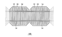
- the solar cell module 100 has a configuration in which collector electrodes 12 provided in a plurality of solar cells 10 are connected to each other by a connecting member 14.
- the connection member 14 is bonded to the collector electrode 12 by a conductive adhesive film in which conductive particles are dispersed (see Patent Document 1).
- connection member 14 when the adhesive force between the solar battery cell 10 and the connection member 14 is reduced, the connection member 14 may be peeled off.
- the amount of the adhesive is excessively increased in order to increase the adhesive force, the adhesive protrudes from the connection member 14, and the solar cell 10 is shielded from light by the protruding adhesive, which may reduce the conversion efficiency.
- One aspect of the present invention includes a plurality of solar cells and a connection member that connects the plurality of solar cells via an adhesive layer, and is more end than the central portion of the solar cell along the longitudinal direction of the connection member. It is a solar cell module which has an adhesion part with a long contact length of an adhesive layer and a connection member in a part.
- Another aspect of the present invention includes a first step of applying an adhesive serving as an adhesive layer to a plurality of solar cells, a second step of connecting a plurality of solar cells with a connecting member via the adhesive layer, Is provided, and an adhesive portion having a longer contact length between the adhesive layer and the connecting member is provided at the end portion than the central portion of the solar cell along the longitudinal direction of the connecting member.
- the solar cell module 200 includes a solar cell 202, a connection member 204, and an adhesive layer 206.
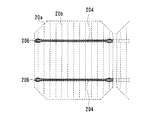
- FIG. 1 is a plan view of the solar cell module 200 as seen from the light receiving surface.
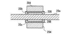
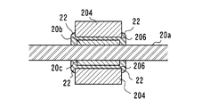
- 2 is a cross-sectional view taken along line AA in FIG. 1
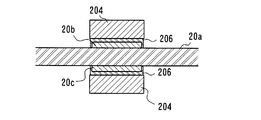
- FIG. 3 is a cross-sectional view taken along line BB in FIG.
- the “light receiving surface” is one of the main surfaces of the solar battery cell 202 and means a surface on which light from the outside is mainly incident. For example, 50% to 100% of the light incident on the solar battery cell 202 is incident from the light receiving surface side.
- the “back surface” is one of the main surfaces of the solar battery cell 202 and means a surface opposite to the light receiving surface.
- the photovoltaic cell 202 receives a light such as sunlight to generate carriers (electrons and holes), a first electrode 20b provided on the light receiving surface of the photoelectric conversion unit 20a, And a second electrode 20c provided on the back surface of the photoelectric conversion unit 20a.
- the first electrode 20 b is a collector electrode including fingers provided in a comb shape so as to intersect the extending direction of the connecting member 204 and a bus bar connecting the fingers.
- the fingers are thin line electrodes that collect power from the photoelectric conversion unit 20a.
- the bus bar is an electrode that connects a plurality of fingers, and is arranged in parallel to each other at a predetermined interval so as to be covered by the connection member 204.
- the fingers and bus bars are formed, for example, by screen-printing a conductive paste in which a conductive filler such as silver (Ag) is dispersed in a binder resin in a desired pattern on a transparent conductive layer.
- the second electrode 20c is provided on the back side of the photoelectric conversion unit 20a in the same manner as the first electrode 20b. In the solar battery cell 202, the carriers generated by the photoelectric conversion unit 20a are collected by the first electrode 20b and the second electrode 20c.
- the area of the second electrode 20c on the back surface may be larger than that of the first electrode 20b on the light receiving surface.
- the second electrode 20c may have more fingers than the first electrode 20b.
- a metal film such as a silver (Ag) thin film may be formed on substantially the entire back surface of the photoelectric conversion unit 20a to form the second electrode 20c.
- the photoelectric conversion unit 20a includes a substrate made of a semiconductor material such as crystalline silicon, gallium arsenide (GaAs), or indium phosphorus (InP).
- the structure of the photoelectric conversion unit 20a is not particularly limited, but in the present embodiment, it will be described as a structure having a heterojunction of an n-type single crystal silicon substrate and amorphous silicon.
- the photoelectric conversion unit 20a includes, for example, an i-type amorphous silicon layer, a p-type amorphous silicon layer doped with boron (B) or the like on a light-receiving surface of an n-type single crystal silicon substrate, indium oxide or the like.
- the transparent conductive layers made of a photoconductive oxide are stacked in this order.
- an i-type amorphous silicon layer, an n-type amorphous silicon layer doped with phosphorus (P) or the like, and a transparent conductive layer are laminated in this order.
- connection member 204 for example, a metal foil such as copper can be used.
- the connection member 204 connects the first electrode 20b of the solar battery cell 202 and the second electrode 20c of the adjacent solar battery cell 202.
- the connection member 204 is bonded to the bus bar and finger of the first electrode 20 b of one solar cell 202 and the bus bar and finger of the second electrode 20 c of the other solar cell 202 by an adhesive layer 206.
- the adhesive layer 206 can be, for example, a conductive adhesive film or a conductive adhesive paste in which conductive particles are dispersed in an adhesive thermosetting resin material such as an epoxy resin, an acrylic resin, or a urethane resin.
- the conductive adhesive film may be an anisotropic conductive adhesive having high conductivity in the in-plane direction of the solar battery cell 202 and low conductivity in the film thickness direction.
- a non-conductive paste containing no conductive particles may be used in an adhesive thermosetting resin material such as an epoxy resin, an acrylic resin, or a urethane resin.
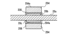
- the first electrode 20b, the second electrode 20c, and the connecting member 204 are provided with unevenness 204a, and the first electrode 20b, second electrode 20c and connecting member are provided via the unevenness 204a. 204 may be electrically connected.
- the connecting member 204 has a bent portion provided with a step corresponding to the thickness of the solar battery cell 202.
- the bent portion forms a structural relief by the thickness of the solar battery cell 202 in order to connect the first electrode 20b and the second electrode 20c so that the adjacent solar battery cells 202 are arranged in the same plane. To be provided.
- Solar cell module 200 may be sealed with a protective member (not shown) in order to protect the light receiving surface and back surface of solar cell 202.
- a protective member for example, a translucent member such as a glass plate, a resin plate, or a resin film can be used.
- the protective member provided on the light receiving surface side of the solar battery cell 202 is preferably a transparent member that transmits light in a wavelength band used for photoelectric conversion in the solar battery cell 202.
- the protective member provided on the back surface side may be an opaque plate or film.
- a laminated film such as a resin film having an aluminum foil or the like inside may be used. The protective member is bonded to the light receiving surface and the back surface of the solar battery cell 202 using a filler.
- the contact lengths of the adhesive layer 206 and the connection member 204 are made different at the end portion and the center portion of the solar cell 202 along the longitudinal direction of the connection member 204. That is, as shown in FIG. 2 and FIG. 3, an adhesive portion in which the contact length between the adhesive layer 206 and the connecting member 204 is longer than the central portion at the end of the solar battery cell 202 along the longitudinal direction of the connecting member 204. To have.
- the contact length between the adhesive layer 206 and the connecting member 204 means that the adhesive layer 206 and the connecting member 204 are in contact with each other in a cross section perpendicular to the longitudinal direction of the connecting member 204. It means the length.
- the edge part and center part of the photovoltaic cell 202 show a relative positional relationship with each other, and the edge part means an area closer to the edge (edge) of the photovoltaic cell 202 than the center part. That is, in this embodiment, when attention is paid to a certain region of the connection member 204, the contact length between the adhesive layer 206 and the connection member 204 in a region closer to the end of the solar battery cell 202 than the focused region is larger than the focused region. Has a long part.
- the width of the adhesive layer 206 is wide at the end of the solar battery cell 202, and the width of the adhesive layer 206 is narrow at the center.
- the adhesive layer 206 may be applied so that At this time, not only the end portion of the connection member 204 but also the end portion of the solar cell 202 on the side where the connection member 204 is drawn out toward the adjacent solar cell 202, the adhesive layer 206 than the central portion of the solar cell 202. It is preferable to provide an adhesive portion having a long contact length between the contact member 204 and the connection member 204.
- the adhesive is applied along the longitudinal direction of the connection member 204 when an adhesive to be the adhesive layer 206 is applied. What is necessary is just to change the application quantity of the adhesive agent used as the layer 206. FIG. For example, more adhesive may be applied at the end of the solar cell 202 in the longitudinal direction of the connection member 204 than at the center, and then the connection member 204 may be pressure-bonded.
- the contact length is made longer than the central part at the end of the solar battery cell 202. Therefore, peeling can be effectively suppressed.
- the contact length is shorter at the center portion than at the end portion, protrusion of the adhesive layer 206 from the connection member 204 can be suppressed at the central portion, and light shielding loss due to the adhesive layer 206 can be suppressed.
- the fillet 22 of the adhesive layer 206 may be formed at the contact portion between the connection member 204 and the first electrode 20 b at the end of the solar battery cell 202.
- the fillet 22 means a part where a part of the adhesive layer 206 is in contact with the side surface of the connection member 204.
- connection member 10 solar cell, 12 collector electrode, 14 connection member, 20a photoelectric conversion unit, 20a solar cell, 20b first electrode, 20c second electrode, 22 fillet, 100, 200 solar cell module, 202 solar cell, 204 connection Member, 206 Adhesive layer.
Landscapes
- Photovoltaic Devices (AREA)
Description
Claims (5)
- 複数の太陽電池と、
接着層を介して前記複数の太陽電池間を接続する接続部材と、
を備え、
前記接続部材の長手方向に沿って前記太陽電池の中央部よりも端部において前記接着層と前記接続部材との接触長さが長い接着部分を有する、太陽電池モジュール。 - 請求項1に記載の太陽電池モジュールであって、
前記接着部分において、前記接続部材の側面と前記接着層とが接触するフィレットを有する、太陽電池モジュール。 - 請求項1又は2に記載の太陽電池モジュールであって、
前記太陽電池における前記接続部材を引き出す側の前記太陽電池の端部において前記太陽電池の中央部よりも前記接着層と前記接続部材との接触長さが長い接着部分を有する、太陽電池モジュール。 - 複数の太陽電池に接着層となる接着剤を塗布する第1の工程と、
前記接着層を介して前記複数の太陽電池間を接続部材によって接続する第2の工程と、
を備え、
前記接続部材の長手方向に沿って前記太陽電池の中央部よりも端部において前記接着層と前記接続部材との接触長さが長い接着部分を設ける、太陽電池モジュールの製造方法。 - 請求項4に記載の太陽電池モジュールの製造方法であって、
前記第1の工程では、前記接続部材の長手方向に沿って前記太陽電池の中央部よりも端部において前記接着剤をより多く塗布する、太陽電池モジュールの製造方法。
Priority Applications (4)
| Application Number | Priority Date | Filing Date | Title |
|---|---|---|---|
| DE112012006613.8T DE112012006613B4 (de) | 2012-06-29 | 2012-06-29 | Solarzellenmodul und Solarzellenmodul-Fertigungsverfahren |
| JP2014522337A JP6249368B2 (ja) | 2012-06-29 | 2012-06-29 | 太陽電池モジュール及び太陽電池モジュールの製造方法 |
| PCT/JP2012/066772 WO2014002269A1 (ja) | 2012-06-29 | 2012-06-29 | 太陽電池モジュール及び太陽電池モジュールの製造方法 |
| US14/560,220 US20150083187A1 (en) | 2012-06-29 | 2014-12-04 | Solar cell module and solar cell module manufacturing method |
Applications Claiming Priority (1)
| Application Number | Priority Date | Filing Date | Title |
|---|---|---|---|
| PCT/JP2012/066772 WO2014002269A1 (ja) | 2012-06-29 | 2012-06-29 | 太陽電池モジュール及び太陽電池モジュールの製造方法 |
Related Child Applications (1)
| Application Number | Title | Priority Date | Filing Date |
|---|---|---|---|
| US14/560,220 Continuation US20150083187A1 (en) | 2012-06-29 | 2014-12-04 | Solar cell module and solar cell module manufacturing method |
Publications (1)
| Publication Number | Publication Date |
|---|---|
| WO2014002269A1 true WO2014002269A1 (ja) | 2014-01-03 |
Family
ID=49782492
Family Applications (1)
| Application Number | Title | Priority Date | Filing Date |
|---|---|---|---|
| PCT/JP2012/066772 Ceased WO2014002269A1 (ja) | 2012-06-29 | 2012-06-29 | 太陽電池モジュール及び太陽電池モジュールの製造方法 |
Country Status (4)
| Country | Link |
|---|---|
| US (1) | US20150083187A1 (ja) |
| JP (1) | JP6249368B2 (ja) |
| DE (1) | DE112012006613B4 (ja) |
| WO (1) | WO2014002269A1 (ja) |
Cited By (1)
| Publication number | Priority date | Publication date | Assignee | Title |
|---|---|---|---|---|
| JP2018107217A (ja) * | 2016-12-22 | 2018-07-05 | パナソニックIpマネジメント株式会社 | 太陽電池モジュールの製造方法及び太陽電池モジュール |
Families Citing this family (2)
| Publication number | Priority date | Publication date | Assignee | Title |
|---|---|---|---|---|
| US11804558B2 (en) * | 2017-12-29 | 2023-10-31 | Maxeon Solar Pte. Ltd. | Conductive contacts for polycrystalline silicon features of solar cells |
| JP2020107758A (ja) * | 2018-12-27 | 2020-07-09 | パナソニック株式会社 | 太陽電池モジュール |
Citations (2)
| Publication number | Priority date | Publication date | Assignee | Title |
|---|---|---|---|---|
| JP2006270043A (ja) * | 2005-02-22 | 2006-10-05 | Kyocera Corp | 太陽電池モジュール |
| JP2012015269A (ja) * | 2010-06-30 | 2012-01-19 | Sanyo Electric Co Ltd | 太陽電池モジュール |
Family Cites Families (5)
| Publication number | Priority date | Publication date | Assignee | Title |
|---|---|---|---|---|
| JP5016342B2 (ja) * | 2006-03-27 | 2012-09-05 | 京セラ株式会社 | 太陽電池モジュール |
| JP4463297B2 (ja) * | 2007-08-07 | 2010-05-19 | 三洋電機株式会社 | 太陽電池モジュール |
| JP5186192B2 (ja) | 2007-12-10 | 2013-04-17 | 信越化学工業株式会社 | 太陽電池モジュール |
| WO2010122875A1 (ja) * | 2009-04-21 | 2010-10-28 | 三洋電機株式会社 | 太陽電池モジュール |
| JP5923732B2 (ja) | 2009-11-20 | 2016-05-25 | パナソニックIpマネジメント株式会社 | 太陽電池モジュール |
-
2012
- 2012-06-29 WO PCT/JP2012/066772 patent/WO2014002269A1/ja not_active Ceased
- 2012-06-29 JP JP2014522337A patent/JP6249368B2/ja active Active
- 2012-06-29 DE DE112012006613.8T patent/DE112012006613B4/de active Active
-
2014
- 2014-12-04 US US14/560,220 patent/US20150083187A1/en not_active Abandoned
Patent Citations (2)
| Publication number | Priority date | Publication date | Assignee | Title |
|---|---|---|---|---|
| JP2006270043A (ja) * | 2005-02-22 | 2006-10-05 | Kyocera Corp | 太陽電池モジュール |
| JP2012015269A (ja) * | 2010-06-30 | 2012-01-19 | Sanyo Electric Co Ltd | 太陽電池モジュール |
Cited By (1)
| Publication number | Priority date | Publication date | Assignee | Title |
|---|---|---|---|---|
| JP2018107217A (ja) * | 2016-12-22 | 2018-07-05 | パナソニックIpマネジメント株式会社 | 太陽電池モジュールの製造方法及び太陽電池モジュール |
Also Published As
| Publication number | Publication date |
|---|---|
| US20150083187A1 (en) | 2015-03-26 |
| JP6249368B2 (ja) | 2017-12-20 |
| DE112012006613T5 (de) | 2015-04-02 |
| JPWO2014002269A1 (ja) | 2016-05-30 |
| DE112012006613B4 (de) | 2022-11-17 |
Similar Documents
| Publication | Publication Date | Title |
|---|---|---|
| JP5687506B2 (ja) | 太陽電池及び太陽電池モジュール | |
| JP5874011B2 (ja) | 太陽電池及び太陽電池モジュール | |
| JP6586080B2 (ja) | 太陽電池モジュールおよびその製造方法 | |
| JP4294048B2 (ja) | 太陽電池モジュール | |
| JP6410106B2 (ja) | 太陽電池モジュール | |
| US20160268964A1 (en) | Solar cell module | |
| JP6241763B2 (ja) | 太陽電池モジュールおよび太陽電池モジュールの製造方法 | |
| WO2013140552A1 (ja) | 太陽電池モジュール | |
| JP6124166B2 (ja) | 太陽電池モジュールおよび太陽電池モジュールの製造方法 | |
| JP6249368B2 (ja) | 太陽電池モジュール及び太陽電池モジュールの製造方法 | |
| JP2007201331A (ja) | 光起電力モジュール | |
| WO2013114555A1 (ja) | 太陽電池モジュール及び太陽電池モジュールの製造方法 | |
| WO2012165001A1 (ja) | 太陽電池モジュール及びその製造方法 | |
| WO2016143249A1 (ja) | 太陽電池モジュール | |
| JP5999570B2 (ja) | 太陽電池モジュール及び太陽電池モジュールの製造方法 | |
| JP6032572B2 (ja) | 太陽電池モジュール及び太陽電池モジュールの製造方法 | |
| JP5906422B2 (ja) | 太陽電池及び太陽電池モジュール | |
| JP6083685B2 (ja) | 太陽電池モジュール及び太陽電池モジュールの製造方法 | |
| WO2013161069A1 (ja) | 太陽電池モジュール及び太陽電池モジュールの製造方法 | |
| WO2014155415A1 (ja) | 太陽電池モジュール | |
| JPWO2013114555A1 (ja) | 太陽電池モジュール及び太陽電池モジュールの製造方法 |
Legal Events
| Date | Code | Title | Description |
|---|---|---|---|
| 121 | Ep: the epo has been informed by wipo that ep was designated in this application |
Ref document number: 12879975 Country of ref document: EP Kind code of ref document: A1 |
|
| ENP | Entry into the national phase |
Ref document number: 2014522337 Country of ref document: JP Kind code of ref document: A |
|
| WWE | Wipo information: entry into national phase |
Ref document number: 112012006613 Country of ref document: DE Ref document number: 1120120066138 Country of ref document: DE |
|
| 122 | Ep: pct application non-entry in european phase |
Ref document number: 12879975 Country of ref document: EP Kind code of ref document: A1 |