WO2013190929A1 - 無線通信システムおよび基地局 - Google Patents
無線通信システムおよび基地局 Download PDFInfo
- Publication number
- WO2013190929A1 WO2013190929A1 PCT/JP2013/063391 JP2013063391W WO2013190929A1 WO 2013190929 A1 WO2013190929 A1 WO 2013190929A1 JP 2013063391 W JP2013063391 W JP 2013063391W WO 2013190929 A1 WO2013190929 A1 WO 2013190929A1
- Authority
- WO
- WIPO (PCT)
- Prior art keywords
- base station
- user
- user plane
- plane path
- established
- Prior art date
Links
Images


Classifications
-
- H—ELECTRICITY
- H04—ELECTRIC COMMUNICATION TECHNIQUE
- H04W—WIRELESS COMMUNICATION NETWORKS
- H04W16/00—Network planning, e.g. coverage or traffic planning tools; Network deployment, e.g. resource partitioning or cells structures
- H04W16/24—Cell structures
- H04W16/32—Hierarchical cell structures
-
- H—ELECTRICITY
- H04—ELECTRIC COMMUNICATION TECHNIQUE
- H04W—WIRELESS COMMUNICATION NETWORKS
- H04W36/00—Hand-off or reselection arrangements
- H04W36/0005—Control or signalling for completing the hand-off
- H04W36/0011—Control or signalling for completing the hand-off for data sessions of end-to-end connection
- H04W36/0027—Control or signalling for completing the hand-off for data sessions of end-to-end connection for a plurality of data sessions of end-to-end connections, e.g. multi-call or multi-bearer end-to-end data connections
-
- H—ELECTRICITY
- H04—ELECTRIC COMMUNICATION TECHNIQUE
- H04W—WIRELESS COMMUNICATION NETWORKS
- H04W72/00—Local resource management
- H04W72/04—Wireless resource allocation
-
- H—ELECTRICITY
- H04—ELECTRIC COMMUNICATION TECHNIQUE
- H04W—WIRELESS COMMUNICATION NETWORKS
- H04W76/00—Connection management
- H04W76/10—Connection setup
- H04W76/12—Setup of transport tunnels
-
- H—ELECTRICITY
- H04—ELECTRIC COMMUNICATION TECHNIQUE
- H04W—WIRELESS COMMUNICATION NETWORKS
- H04W36/00—Hand-off or reselection arrangements
- H04W36/0005—Control or signalling for completing the hand-off
- H04W36/0083—Determination of parameters used for hand-off, e.g. generation or modification of neighbour cell lists
- H04W36/0085—Hand-off measurements
- H04W36/0088—Scheduling hand-off measurements
Definitions
- the present invention relates to a wireless communication system and a base station.
- a logical communication path (user plane path) used for user data communication is an eNB that is a radio base station. It is established in the gateway device and the user device via (evolved Node B). The user apparatus performs communication with an external network (such as the Internet) using the established user plane path.
- LTE / SAE Long Term Evolution / Large System Evolution Architecture
- the eNB has a communication path (control plane path) for transmitting / receiving control signals to / from other eNBs, exchanges, and user apparatuses.
- control plane path control plane path
- the eNB connected to the user apparatus moves to a cell formed by another eNB
- the eNB transmits / receives a control message to / from the user apparatus and another eNB via the control plane path, Operate to be handed over to the eNB.
- the route is changed so that the user plane route passes through the handover destination eNB.
- the wireless communication system includes a base station (a base station with a limited control function) that is connected to the eNB and does not have a control plane path for the user apparatus.
- a base station a base station with a limited control function
- Such a base station is connected to the eNB, but not connected to the gateway device, and thus cannot directly transmit / receive user data to / from the gateway device.
- a base station does not have a control plane path
- an object of the present invention is to realize a wireless communication system including a base station having a limited control function.
- the radio communication system of the present invention includes a user apparatus, a first base station that can execute radio resource control of the user apparatus via a control plane path, and a second base that does not execute radio resource control of the user apparatus.
- a measurement report message receiving unit that includes a plurality of base stations including a station and a gateway device, wherein the first base station receives a measurement report message about a radio wave transmitted by the base station, transmitted from the user device.
- the third user plane path is established between the first base station and the second base station, and there is no control plane path to the user apparatus (the radio resource control of the user apparatus is not executed).
- a fourth user plane path is established between the two base stations and the user equipment. Therefore, the user apparatus can transmit and receive user signals via the second base station that is not directly connected to the gateway apparatus. That is, a radio communication system including a second base station that does not execute radio resource control of a user apparatus (with a limited control function) is realized.
- Another radio communication system of the present invention includes a user apparatus, a first base station that can execute radio resource control of the user apparatus via a control plane path, and a radio resource control of the user apparatus that does not execute radio resource control.
- a plurality of base stations including two base stations, a switching center, and a gateway device, wherein the first base station receives a measurement report message regarding radio waves from the base station transmitted from the user device
- a measurement report message receiving unit and a transfer unit configured to transfer the measurement report message to the exchange.
- the exchange includes a control plane path and a first user plane path between the user apparatus and the first base station.
- the first base station and the second base station A determination unit configured to determine whether or not a user plane path should be established based on the measurement report message; and a determination result transmission unit configured to transmit a determination result of the determination unit to the first base station.
- the station further establishes the third user plane path to the first base station and the second base station when the determination result indicates a determination that the third user plane path should be established;
- a user plane path control unit for associating the established third user plane path with the second user plane path, and a wireless connection for instructing the user apparatus and the second base station to establish a fourth user plane path
- a wireless connection setting unit that transmits a reconfiguration message to the user apparatus, and the second base station transmits the fourth user plane path established by the user apparatus to the user apparatus.
- 3 comprises a user plane route processing unit for associating the user plane path.
- the third user plane path is established between the first base station and the second base station, and there is no control plane path to the user apparatus (the radio resource control of the user apparatus is not executed).
- a fourth user plane path is established between the two base stations and the user equipment. Therefore, the user apparatus can transmit and receive user signals via the second base station that is not directly connected to the gateway apparatus. That is, a radio communication system including a second base station that does not execute radio resource control of a user apparatus (with a limited control function) is realized.
- the user plane path control unit of the first base station releases the first user plane path after the third user plane path and the fourth user plane path are associated with each other.
- the user apparatus can transmit and receive user signals via the second base station, the first user plane path established between the user apparatus and the first base station is Since it is released, the continuity of wireless communication is maintained, and at the same time, efficient use of wireless resources is realized.
- the user plane path control unit of the first base station includes the identification information of the first base station and requests to establish the third user plane path.
- the user plane path processing unit of the second base station transmits a path establishment response message including identification information of the second base station
- the wireless connection setting unit of the first base station transmits the wireless connection reconfiguration message including the identification information of the second base station to the user device, and the user device transmits the wireless connection reconfiguration message to the user device.
- a communication control unit that establishes the fourth user plane path by accessing the second base station based on the second base station; According to the above configuration, the first base station having a control plane path for the user apparatus transmits a radio connection reconfiguration message to the user apparatus on behalf of the second base station not having the control plane path for the user apparatus. Thus, a wireless connection (fourth user plane route) between the user apparatus and the second base station is established.
- Another radio communication system of the present invention includes a user apparatus, a first base station that can execute radio resource control of the user apparatus via a control plane path, and a radio resource control of the user apparatus that does not execute radio resource control.
- a measurement report message that includes a plurality of base stations including two base stations, and a gateway device, wherein the first base station receives a measurement report message related to radio waves transmitted by the base station, transmitted from the user device.
- a control plane path is established between the receiving unit, the user apparatus and the first base station, a second user plane path is established between the gateway apparatus and the first base station, and the first base station and the first base station A third user plane path is established with the second base station in association with the second user plane path, and a fourth user plane is established with the second base station and the user apparatus. Determining whether or not a first user plane route should be established between the user equipment and the first base station based on the measurement report message when a second route is established in association with the third user plane route And a user plane path control unit that establishes the first user plane path to the user apparatus and the first base station when the determination unit determines that the first user plane path should be established. With.
- the first user plane path is established between the user apparatus and the first base station. Therefore, it becomes possible for the user apparatus that initially performed wireless communication via the second base station to transmit and receive user signals via the first base station. That is, a radio communication system including a second base station that does not execute radio resource control of a user apparatus (with a limited control function) is realized.
- the user plane path control unit of the first base station releases the fourth user plane path when the determination unit determines that the first user plane path should be established.
- a route release request message requesting to be transmitted to the second base station, the second base station releasing the fourth user plane route based on the route release request message, and the fourth user plane route
- a user plane route processing unit that transmits a route release response message to the first base station after the release, and when the user plane route control unit of the first base station receives the route release response message, Release the 3 user plane path.
- Another radio communication system of the present invention includes a user apparatus, a first base station that can execute radio resource control of the user apparatus via a control plane path, and a radio resource control of the user apparatus that does not execute radio resource control.
- a plurality of base stations including two base stations, a switching center, and a gateway device, wherein the first base station receives a measurement report message related to radio waves transmitted from the base station, transmitted from the user device;
- a measurement report message receiving unit configured to transfer the measurement report message to the exchange, and the exchange establishes a control plane path between the user apparatus and the first base station, and the gateway
- a second user plane path is established between the device and the first base station, and a third user plane path is established between the first base station and the second base station.
- a determination unit that determines whether to establish a first user plane path based on the measurement report message, and a determination result transmission unit that transmits a determination result of the determination unit to the first base station, The first base station further establishes the first user plane path to the user apparatus and the first base station when the determination result indicates a determination that the first user plane path should be established. And a user plane route control unit.
- the first user plane path is established between the user apparatus and the first base station. Therefore, it becomes possible for the user apparatus that initially performed wireless communication via the second base station to transmit and receive user signals via the first base station. That is, a radio communication system including a second base station that does not execute radio resource control of a user apparatus (with a limited control function) is realized.
- the user plane path control unit of the first base station determines the fourth user plane path.
- the second base station releases the fourth user plane route based on the route release request message, and the fourth user A user plane route processing unit that transmits a route release response message to the first base station after releasing the plane route, and the user plane route control unit of the first base station receives the route release response message; Release the third user plane path.
- the first base station includes a wireless connection control unit capable of transmitting a wireless connection reconfiguration message
- the user plane path control unit of the first base station includes the first user plane.
- the user plane path is associated with the second user plane path and the first user plane path
- a radio connection reconfiguration message instructing the user apparatus and the first base station to establish the first user plane path
- the wireless connection control unit is controlled so as to be transmitted to the user apparatus.
- the base station of the present invention includes a user apparatus, a first base station that can execute radio resource control of the user apparatus via a control plane path, and a second base station that does not execute radio resource control of the user apparatus.
- a first base station used in a wireless communication system comprising a plurality of base stations including a gateway device, and receiving a measurement report message regarding radio waves transmitted from the user station and transmitted from the user device
- a control plane path and a first user plane path are established between the measurement report message receiver, the user apparatus and the first base station, and a second user plane path is established between the first base station and the gateway apparatus.
- the third user plane path is established between the first base station and the second base station.
- a user plane path control unit that associates the established third user plane path with the second user plane path, and a radio that instructs the user apparatus and the second base station to establish a fourth user plane path
- a wireless connection setting unit that transmits a connection reset message to the user apparatus.
- Another base station of the present invention includes a user apparatus, a first base station that can execute radio resource control of the user apparatus via a control plane path, and a second that does not execute radio resource control of the user apparatus.
- a first base station used in a wireless communication system including a plurality of base stations including a base station and a gateway device, wherein a measurement report message related to radio waves transmitted from the user station is transmitted from the user device.
- a control plane path is established between the receiving measurement report message receiving unit, the user apparatus and the first base station, and a second user plane path is established between the gateway apparatus and the first base station.
- a third user plane path is established between the base station and the second base station in association with the second user plane path, and the second base station and the user equipment are And the fourth user plane path is established in association with the third user plane path, the measurement report as to whether or not the first user plane path should be established between the user apparatus and the first base station.
- the determination unit determines based on the message and the determination unit determines that the first user plane route should be established, the first user plane route is established between the user apparatus and the first base station. And a user plane route control unit.
- FIG. 1 is a block diagram showing a wireless communication system according to a first embodiment of the present invention. It is explanatory drawing which shows an example of the GTP tunnel establishment operation
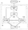
- FIG. 1 is a block diagram showing a radio communication system CS according to the first embodiment of the present invention.
- the radio communication system CS includes a user apparatus UE, a first base station eNB, a second base station PhNB, an exchange MME, and a gateway apparatus GW as elements. Further, the network NW includes all the elements of the user apparatus UE among the elements included in the radio communication system CS.
- Each element in the radio communication system CS executes communication according to a predetermined access technology (LTE / SAE (Long Term Evolution / System Architecture Evolution) defined in 3GPP standard (Third Generation Partnership Project), for example.
- LTE / SAE Long Term Evolution / System Architecture Evolution
- 3GPP standard Third Generation Partnership Project
- the user apparatus UE is User Equipment
- the first base station eNB is evolved Node B
- the switching center MME is a Mobile Management Entity
- the gateway apparatus GW is Packet-Data-Network.
- SAE Gateway Serving Gateway
- the second base station PhNB is a base station that relies on the first base station eNB for all or part of its control function (details will be described later).
- the user apparatus UE can wirelessly communicate with the first base station eNB and the second base station PhNB.
- a method of radio communication between the user apparatus UE and each base station (eNB, PhNB) is arbitrary.
- OFDMA Orthogonal Frequency Division Multiple Access
- SC-FDMA Single-Carrier Frequency Division Multiple Access
- the first base station eNB is connected to the second base station PhNB, the exchange MME, and the gateway device GW by wire.
- the second base station PhNB is connected to the first base station eNB by wire.
- a configuration in which the first base station eNB and the second base station PhNB are wirelessly connected can also be employed.
- the gateway device GW is connected to the first base station eNB and the switching center MME, and is also connected to the Internet IN that is an external network of the radio communication system CS. That is, the gateway device GW can function as a connection point (access point) with an external network.
- a solid line indicates a path used for transmission / reception of a user signal (a signal indicating user data such as a voice signal and a data signal), and a broken line indicates a path used for transmission / reception of a control signal. That is, a solid line indicates an interface of a U plane (user plane, User Plane), and a broken line indicates an interface of a C plane (control plane, Control Plane).
- a U-plane path is established through the U-plane interface
- a C-plane path is established through the C-plane interface.
- EPS Evolved Packet System
- 3GPP Third Generation Partnership Project
- an X3 interface exists between the first base station eNB and the second base station PhNB, and Ph-Uu between the second base station PhNB and the user apparatus UE.
- An interface exists. Note that there is no C-plane interface between the second base station PhNB and the user apparatus UE.
- a bearer is a dynamic logical path that is established and released as needed.
- a data radio bearer DRB is established between the user apparatus UE and the first base station eNB or between the user apparatus UE and the second base station PhNB.
- An X3 bearer X3B is established between the first base station eNB and the second base station PhNB.
- An S1 bearer is established between the first base station eNB and the gateway device GW.
- a bearer (X3 bearer X3B, S1 bearer, etc.) established in the network NW is also called a GTP (GPRS (General Packet Radio Service) Tunneling Protocol) tunnel.
- GTP General Packet Radio Service
- the user apparatus UE can communicate with the Internet IN via an upper bearer (EPS bearer) including the data radio bearer DRB and the S1 bearer established in the user apparatus UE and the first base station eNB, and the user apparatus UE It is possible to communicate with the Internet IN via higher rank bearers including data radio bearers DRB, X3 bearers X3B, and S1 bearers established with the second base station PhNB.
- EPS bearer upper bearer
- DRB data radio bearer
- S1 bearer established in the user apparatus UE and the first base station eNB
- higher rank bearers including data radio bearers DRB, X3 bearers X3B, and S1 bearers established with the second base station PhNB.
- Each node in the radio communication system CS has unique identification information.
- the identification information may include the IP address, TEID (tunnel end point ID), network address, etc. of the node. Further, the identification information of the first base station eNB and the second base station PhNB may include a physical cell ID (Physical Cell ID) for identifying the cell C formed by the base station.
- the IP address is an address value that uniquely identifies the node in the radio communication system CS.
- the TEID is an identifier that identifies an end point of a GTP tunnel that logically connects nodes.
- the network address is an address value for identifying a subnet to which the node belongs when the radio communication system CS is divided into a plurality of subnets.
- a node in the wireless communication system CS identifies another node based on the identification information of the other node.
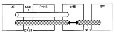
- the S1 bearer S1B is established in the gateway device GW and the first base station eNB, and the data radio bearer DRB1 associated with the S1 bearer S1B is established in the first base station eNB and the user device UE.
- the user apparatus UE initially performs transmission / reception of a user signal only through the first base station eNB that is wirelessly connected.
- a signaling radio bearer SRB is initially established between the user apparatus UE and the first base station eNB.
- the user apparatus UE measures the received power (reception quality) of radio waves transmitted by nearby base stations, and reports it to the first base station eNB that is wirelessly connected. More specifically, the user apparatus UE sends a measurement report message (measurement report message) loaded with information indicating reception power (reception quality) of radio waves (reference signals) transmitted by neighboring base stations (eNB, PhNB). And transmits to the first base station eNB via the C-plane path (signaling radio bearer SRB) (S100).
- the Measurement Report message includes information indicating received power from the first base station eNB and information indicating received power from the second base station PhNB.
- the first base station eNB When the first base station eNB receives the Measurement Report message transmitted from the user apparatus UE, whether or not the user apparatus UE should transmit and receive a user signal via the second base station PhNB, that is, the first base station eNB And whether or not a U-plane path (GTP tunnel) should be established with the second base station PhNB (S120).
- the above determination is performed based on, for example, a criterion “whether the reception power of the radio wave from the second base station PhNB is larger than the reception power of the radio wave from the currently connected first base station eNB”.
- step S120 since the first base station eNB has higher received power from the second base station PhNB than received power from the first base station eNB, the first base station eNB and the second base station PhNB Assume that it is determined that a U-plane path should be established.
- the first base station eNB After the determination in step S120, the first base station eNB sends a Tunnel Setup Request message (tunnel establishment request message) instructing the first base station eNB and the second base station PhNB to establish a U-plane path to the second base station. Transmit to the station PhNB (S140).
- the Tunnel Setup Request message includes identification information of the first base station eNB.
- the second base station PhNB When the second base station PhNB receives the Tunnel Setup Request message, after establishing the logical connection (uplink logical connection) to the first base station eNB based on the identification information of the first base station eNB included in the Tunnel Setup Request message Then, a Tunnel Setup Complete message (tunnel establishment completion message) including the identification information of the second base station PhNB and access layer setting information (AS Config) is transmitted to the first base station eNB (S160).
- the access layer setting information includes timing information of a random access channel (Random Access Channel, RACH) necessary for synchronizing the user apparatus UE and the second base station PhNB.
- RACH Random Access Channel
- the first base station eNB When receiving the Tunnel Setup Complete message, the first base station eNB establishes a logical connection (downward logical connection) to the second base station PhNB based on the identification information of the second base station PhNB included in the Tunnel Setup Complete message. As described above, the first base station eNB takes the initiative to establish the X3 bearer X3B that is the U-plane path (GTP tunnel) between the first base station eNB and the second base station PhNB (S180).
- GTP tunnel U-plane path
- the first base station eNB associates (maps) the established U-plane path (X3 bearer X3B) with the S1 bearer S1B established in the gateway device GW and the first base station eNB (S200).
- FIG. 4 is a diagram illustrating a logical path after the mapping in step S200.
- an X3 bearer X3B Indicates the established state.
- the first base station eNB sends an RRC Connection Reconfiguration message (radio connection reconfiguration message) instructing the second base station PhNB and the user apparatus UE to establish a new data radio bearer DRB2. It transmits to the user apparatus UE currently connected (S220).
- the RRC Connection Reconfiguration message includes information necessary for the user apparatus UE to wirelessly connect to the second base station PhNB (identification information and access layer setting information of the second base station PhNB).
- the user apparatus UE establishes the data radio bearer DRB2 to the second base station PhNB according to the received RRC Connection Reconfiguration message. More specifically, after performing synchronization with the second base station PhNB based on the identification information of the second base station PhNB included in the received RRC Connection Reconfiguration message, the access layer setting information is used to 2. Access to the base station PhNB (S240). When the user apparatus UE successfully accesses the second base station PhNB, establishment of a new data radio bearer DRB2 is completed (S260). That is, the user apparatus UE establishes a new data radio bearer DRB2 by accessing the second base station PhNB according to the RRC Connection Reconfiguration message.
- the second base station PhNB associates (maps) the established new data radio bearer DRB2 with the X3 bearer X3B established in the first base station eNB and the second base station PhNB (S280).
- FIG. 5 is a diagram illustrating the logical path after the mapping in step S280, and the user apparatus UE and the gateway apparatus GW logically pass through the new data radio bearer DRB2, X3 bearer X3B, and S1 bearer S1B. Indicates that it has been connected.
- the user apparatus UE transmits an RRC Connection Reconfiguration Complete message (radio connection reconfiguration complete message) indicating that a new data radio bearer DRB2 has been established to the first base station eNB (S300). Note that the user apparatus UE may transmit an RRC Connection Reconfiguration Complete message to the first base station eNB after establishment of a new data radio bearer DRB2 (S260).
- RRC Connection Reconfiguration Complete message radio connection reconfiguration complete message
- the first base station eNB After the newly established data radio bearer DRB2 and X3 bearer X3B are associated (or after receiving the RRC ⁇ ⁇ ⁇ ⁇ Connection Reconfiguration Complete message), the first base station eNB communicates with the user apparatus UE and the first base station. It is possible to release the established data radio bearer DRB1 (S320). Note that step S320 may not be executed, and both data radio bearers DRB1 may be maintained. In any case, the signaling radio bearer SRB established in the user apparatus UE and the first base station is maintained.
- a GTP tunnel (X3 bearer X3B), which is a U-plane path, is established between the first base station eNB and the second base station PhNB, and a new one is added to the second base station PhNB and the user apparatus UE.
- a data radio bearer DRB2 is established.
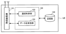
- FIG. 6 is a block diagram illustrating a configuration of the user device UE according to the first embodiment.
- the user apparatus UE includes a radio communication unit 110, a control unit 120, and a storage unit 130. Illustrations of an output device that outputs audio, video, and the like, an input device that receives an instruction from a user, and the like are omitted for convenience.
- the wireless communication unit 110 is an element for performing wireless communication with the first base station eNB and the second base station PhNB, a transmission / reception antenna, and a receiving circuit that receives a radio signal (radio wave) and converts it into an electrical signal.
- a transmission circuit that converts electrical signals such as control signals and user signals into radio signals and transmits them.
- the storage unit 130 stores information related to communication control, particularly identification information of each node including its own station and context information of communication paths (C plane path, U plane path).
- the control unit 120 includes a communication control unit 122 and a data transmission / reception unit 124.
- the communication control unit 122 is an element that controls radio communication between the user apparatus UE and each base station (first base station eNB, second base station PhNB), and the radio communication unit 110 is configured using the signaling radio bearer SRB. Control signals (control messages) are transmitted / received to / from each base station. That is, the communication control unit 122 executes communication on the C plane. For example, as described above, the communication control unit 122 measures the reception power of the radio wave from the nearby base station, mounts it in the Measurement Report message, and transmits it to the first base station eNB.
- the communication control unit 122 accesses the second base station PhNB based on the RRC Connection Reconfiguration message transmitted by the first base station eNB, and establishes the data radio bearer DRB2 to the user apparatus UE and the second base station PhNB.
- the data transmission / reception unit 124 transmits / receives user signals to / from each base station via the radio communication unit 110 using the data radio bearer DRB. That is, the data transmission / reception unit 124 performs communication on the U plane.
- a CPU Central Processing Unit
- the user apparatus UE executes a computer program stored in the storage unit 130, It is a functional block realized by functioning according to the computer program.
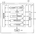
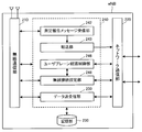
- FIG. 7 is a block diagram showing a configuration of the first base station eNB according to the first embodiment.
- the first base station eNB includes a radio communication unit 210, a network communication unit 220, a storage unit 230, and a control unit 240.
- the radio communication unit 210 is an element for executing radio communication with the user apparatus UE, and has the same configuration as the radio communication unit 110 of the user apparatus UE.
- the network communication unit 220 is an element for performing communication with other nodes (second base station PhNB, switching center MME, gateway device GW, etc.) in the network NW, and transmits and receives electrical signals to and from other nodes.
- the storage unit 230 stores information related to communication control, particularly identification information of each node including its own station, and context information of communication paths (C plane path, U plane path).
- the control unit 240 is an element that controls communication with other nodes such as the user apparatus UE and the second base station PhNB, and in particular, wireless connection with the measurement report message reception unit 242, the determination unit 244, and the U-plane path control unit 246.
- a setting unit 248 and a data transmission / reception unit 250 are provided.
- the measurement report message reception unit 242 receives the Measurement-Report message transmitted by the user apparatus UE via the wireless communication unit 210 and supplies it to the determination unit 244.
- the determination unit 244 executes the determination of establishment of the U-plane route (GTP tunnel) in step S120 described above.
- the U plane path control unit 246 controls establishment of a U plane path (particularly, X3 bearer X3B) based on the determination of the determination unit 244. Further, the U plane path control unit 246 associates (maps) one U plane path with another U plane path.
- the radio connection setting unit 248 transmits the RRC Connection Reconfiguration message using the C plane path (signaling radio bearer SRB), and performs radio resource control (such as establishment / release of the radio bearer RB) of the user apparatus UE.
- the data transmitting / receiving unit 250 transmits / receives (relays) user signals to / from the user apparatus UE via the data radio bearer DRB, and transmits / receives (relays) user signals to / from the gateway apparatus GW via the S1 bearer S1B.
- the control unit 240 performs communication on the C plane and the U plane.
- control unit 240 and the measurement report message reception unit 242, the determination unit 244, the U plane path control unit 246, the radio connection setting unit 248, and the data transmission / reception unit 250 included in the control unit 240 are not illustrated in the first base station eNB. Is a functional block realized by executing a computer program stored in the storage unit 230 and functioning according to the computer program.
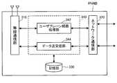
- FIG. 8 is a block diagram showing a configuration of the second base station PhNB according to the first embodiment.
- the second base station PhNB includes a wireless communication unit 310, a network communication unit 320, a storage unit 330, and a control unit 340.
- the radio communication unit 310 is an element for executing radio communication with the user apparatus UE, and has the same configuration as the radio communication unit 210 of the first base station eNB.
- the network communication unit 320 is an element for performing communication with the first base station eNB, and transmits and receives electrical signals to and from the first base station eNB.
- the storage unit 330 includes information related to the communication business, in particular, identification information of each node including its own station and context information of communication paths (C plane path and U plane path).
- the control unit 340 includes a U-plane path processing unit 342 and a data transmission / reception unit 344.
- the U plane path processing unit 342 establishes a logical connection with the first base station eNB according to the control of the first base station eNB (Tunnel Setup Request message), and then sends a Tunnel Setup Setup Complete message. Transmit to one base station eNB.
- the U plane route processing unit 342 associates (maps) one U plane route with another U plane route.
- the control part 340 does not perform radio
- the data transmitter / receiver 344 transmits / receives (relays) user signals to / from the user apparatus UE via the data radio bearer DRB, and also via the X3 bearer X3B and the S1 bearer S1B (that is, via the first base station eNB) GW and user signals are transmitted / received (relayed). That is, the data transmission / reception unit 344 performs communication on the U plane.
- control unit 340 and the U plane path processing unit 342 and the data transmission / reception unit 344 included in the control unit 340 are executed by a CPU (not shown) in the second base station PhNB executing a computer program stored in the storage unit 330, It is a functional block realized by functioning according to a computer program.
- FIG. 9 is a block diagram showing the configuration of the switching center MME according to the first embodiment.
- the switching center MME includes a network communication unit 410, a storage unit 420, and a control unit 430.
- the network communication unit 410 is an element for executing communication with other nodes (gateway device GW, first base station eNB, etc.) in the network NW, and has the same configuration as the network communication unit 220 of the first base station eNB.
- Have The storage unit 420 stores information regarding communication control, in particular, identification information of each node including its own station and context information of communication paths (C plane path, U plane path).
- the control unit 430 is a communication control unit that performs communication control of the radio communication system CS, and transmits and receives control signals to and from other nodes.
- the exchange MME (control unit 430) executes communication on the C plane and does not execute communication on the U plane.
- the control unit 430 is a functional block realized by a CPU (not shown) in the exchange MME executing a computer program stored in the storage unit 420 and functioning according to the computer program.
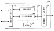
- FIG. 10 is a block diagram illustrating a configuration of the gateway device GW according to the first embodiment.
- the gateway device GW includes a network communication unit 510, an external network communication unit 520, a storage unit 530, and a control unit 540.
- the network communication unit 510 is an element for executing communication with other nodes (first base station eNB, switching center MME, etc.) in the network NW, and has the same configuration as the network communication unit 220 of the first base station eNB.
- the external network communication unit 520 is an element for executing communication with the Internet IN, and executes protocol conversion of user signals as necessary.
- the storage unit 530 stores information related to communication control, particularly identification information of each node including its own station and context information of communication paths (C plane path, U plane path).
- the control unit 540 includes a communication control unit 542 and a data transmission / reception unit 544.
- the communication control unit 542 is an element that executes communication control of the radio communication system CS, and transmits and receives control signals to and from the exchange MME through the network communication unit 510. That is, the communication control unit 542 executes communication on the C plane via the network communication unit 510.
- the data transmitter / receiver 544 transmits the user signal from the user apparatus UE received via the network communication unit 510 to the Internet IN (external server in the Internet IN) via the external network communication unit 520.
- a user signal received from the Internet IN (external server in the Internet IN) via the external network communication unit 520 is transmitted (relayed) to the user apparatus UE via the network communication unit 510. That is, the data transmitting / receiving unit 524 executes communication on the U plane.
- the control unit 540 and the communication control unit 542 and the data transmission / reception unit 544 included in the control unit 540 have a CPU (not shown) in the gateway device GW execute a computer program stored in the storage unit 530 and function according to the computer program It is a functional block realized by doing.
- a GTP tunnel (X3 bearer X3B), which is a U-plane path, is established between the first base station eNB and the second base station PhNB, and is transmitted to the user apparatus UE.
- the data radio bearer DRB2 that is the U plane path is established between the second base station PhNB and the user apparatus UE that do not have the C plane path. Therefore, the user apparatus UE can transmit and receive user signals via the second base station PhNB that is not directly connected to the gateway apparatus GW. That is, the radio communication system CS including the second base station PhNB that does not execute the radio resource control of the user apparatus UE (the control function is limited) is realized.
- a U-plane path is established between the first base station eNB and the second base station PhNB.
- the U-plane path established between the first base station eNB and the second base station PhNB can be released.
- the S1 bearer S1B is established in the gateway device GW and the first base station eNB, and the X3 bearer X3B associated with the S1 bearer S1B is in the first base station eNB and the second base station PhNB. It is assumed that the data radio bearer DRB2 established and associated with the X3 bearer X3B is established with the second base station PhNB and the user equipment UE (FIG. 12). That is, in the example of FIG.
- the user apparatus UE sends a measurement report message including information indicating reception power (reception quality) of radio waves (reference signals) transmitted by neighboring base stations (eNB, PhNB) to the C plane. It transmits to the first base station eNB via the route (S500).
- the first base station eNB determines whether or not the U plane path (GTP tunnel) established between the first base station eNB and the second base station PhNB should be released (S520).
- step S520 since the first base station eNB (determination unit 244) has a higher received power from the first base station eNB than a received power from the second base station PhNB, It is assumed that it is determined that the data radio bearer DRB1 should be established with the base station eNB.
- the first base station eNB (U-plane path control unit 246) instructs to release the data radio bearer DRB2 currently established in the user apparatus UE and the second base station PhNB.
- a Request message (bearer release request message) is transmitted to the second base station PhNB (S540).
- the second base station PhNB (U-plane path processing unit 342) releases the currently established data radio bearer DRB2 based on the received BearerBRelease Request message (S560). With the release of the data radio bearer DRB2, the association between the data radio bearer DRB2 and the X3 bearer X3B is disassociated.
- the second base station PhNB (U-plane path processing unit 342) transmits a Bearer Release Response message (bearer release response message) indicating that the data radio bearer DRB2 has been released to the first base station eNB. (S580).
- the first base station eNB (U-plane path control unit 246) releases the X3 bearer X3B (GTP tunnel) (S600). With the release of the X3 bearer X3B, the association between the X3 bearer X3B and the S1 bearer S1B is disconnected.
- the first base station eNB After releasing the GTP tunnel in step S600, the first base station eNB sets (establishes) the data radio bearer DRB1 in the user apparatus UE and the first base station eNB (S620). Specifically, as illustrated in FIG. 13, the U plane path control unit 246 of the first base station eNB already has a U plane path (data radio bearer DRB) between the user apparatus UE and the first base station eNB. It is determined whether or not it exists (S622). When the data radio bearer DRB exists (S622: YES), the first base station eNB associates the existing data radio bearer DRB with the S1 bearer S1B established in the gateway device GW and the first base station eNB. (Mapping) (S624).
- mapping mapping
- the U-plane path control unit 246 of the first base station eNB controls the radio connection setting unit 248 to control the user apparatus UE, the first base station eNB, The user apparatus UE is caused to transmit an RRC Connection Reconfiguration message instructing to establish a new data radio bearer DRB (S626).
- the U-plane path control unit 246 associates (maps) the established new data radio bearer DRB with the S1 bearer S1B (S628).
- the data radio bearer DRB1 is established between the user apparatus UE and the first base station eNB as described above.
- Steps S540 to S600 release of data radio bearer DRB2 and X3 bearer X3B
- the data radio bearer DRB1 may be set in the user apparatus UE and the first base station eNB while maintaining the already established data radio bearer DRB2 and X3 bearer X3B.
- the GTP tunnel (X3 bearer X3B) that is the U-plane path established between the first base station eNB and the second base station PhNB can be released.
- the data radio bearer DRB1 is established between the user apparatus UE and the first base station eNB. Therefore, the user apparatus UE that initially performed radio communication via the second base station PhNB can transmit and receive user signals via the first base station eNB. That is, the radio communication system CS including the second base station PhNB that does not execute the radio resource control of the user apparatus UE (the control function is limited) is realized.
- the first base station eNB includes a determination unit that determines whether to establish and release a U-plane path.
- the exchange MME includes the determination unit as described above.
- FIG. 14 is a block diagram showing a configuration of the first base station eNB according to the third embodiment.
- the transfer unit 243 included in the first base station eNB (control unit 240) is a functional block that transfers the Measurement Report message received by the measurement report message receiving unit 242 to the switching center via the network communication unit 220.
- the control unit 240 of the first base station eNB does not include the determination unit 244.
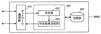
- FIG. 15 is a block diagram showing the configuration of the switching center MME according to the third embodiment.
- the control unit 430 of the exchange MME includes a determination unit 432 and a determination result transmission unit 434.
- the determination unit 432 is a functional block similar to the determination unit 244 included in the first base station eNB of the first embodiment and the second embodiment.
- the determination unit 432 determines whether or not an X3 bearer X3B should be established between the first base station eNB and the second base station PhNB based on the Measurement Report message transferred from the first base station eNB.
- the determination part 432 determines whether data radio bearer DRB1 should be established between the user apparatus UE and the 1st base station eNB based on the Measurement Report message transferred from the 1st base station eNB.
- the determination result transmission unit 434 is a functional block that transmits the determination result by the determination unit 432 to the first base station eNB (U-plane path control unit 246) via the network communication unit 410.
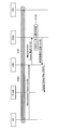
- the user apparatus UE transmits a Measurement Report message to the first base station eNB as in the first embodiment (S100).
- the first base station eNB transfers the message to the exchange MME (S110).
- the exchange MME determination unit 432 receives the Measurement Report message transferred from the first base station eNB
- the user apparatus UE passes through the second base station PhNB as in the first base station eNB of the first embodiment.
- the exchange MME determines whether or not the user signal should be transmitted / received, that is, whether or not the U plane path (GTP tunnel) should be established between the first base station eNB and the second base station PhNB (S120).
- the exchange MME determineation result transmission unit 434) transmits the determination result in step S120 to the first base station eNB (S130).
- the above determination result indicates a determination that a U-plane path should be established between the first base station eNB and the second base station PhNB.
- the first base station eNB (U-plane path control unit 246) transmits a Tunnel Setup Request message to the second base station PhNB based on the received determination result (S140). Subsequent operations are the same as those in the first embodiment (FIG. 2).
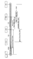
- the user apparatus UE transmits a Measurement Report message to the first base station eNB as in the second embodiment (S500).
- the first base station eNB transfers the message to the exchange MME (S510).
- the switching center MME determineation unit 432 communicates with the user apparatus UE and the first base station eNB in the same manner as the first base station eNB of the second embodiment.
- the exchange MME determines whether or not the U plane path should be established (and whether or not the U plane path established between the first base station eNB and the second base station PhNB should be released) (S520).
- the exchange MME determineation result transmission unit 434) transmits the determination result in step S520 to the first base station eNB (S530).
- the above determination result indicates a determination that the data radio bearer DRB1 should be established between the user apparatus UE and the first base station eNB.
- the first base station eNB (U-plane path control unit 246) transmits a Bearer Release Request message to the second base station PhNB based on the received determination result (S540).
- Subsequent operations are the same as those in the second embodiment (FIG. 11). Similar to the second embodiment, the operations from step S540 to S600 (release of data radio bearer DRB2 and X3 bearer X3B) may be skipped.
- the gateway device GW is described as a single device.
- the gateway device GW may be configured by a plurality of devices, for example, a serving gateway (Serving Gateway) and a PDN gateway (Packet Data Network Gateway) defined in the LTE / SAE standard.
- a serving gateway Serving Gateway
- PDN gateway Packet Data Network Gateway
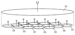
- the size of the cell C (range in which radio waves effectively reach) formed around each base station is arbitrary.
- the small cells C2 are formed in layers (overlaid) inside the macrocell C1 (a plane on which the macrocell C1 is shown for convenience of drawing).
- the macro cell C1 and the small cell C2 may be superimposed on the same plane (the ground surface or the like).
- a configuration in which the first base station eNB and the second base station PhNB form a cell C having substantially the same size can also be employed.
- Modification 4 A configuration in which the frequency band of the radio wave transmitted by the first base station eNB and the frequency band of the radio wave transmitted by the second base station PhNB are different can also be adopted.
- the first base station eNB performs radio communication using a first frequency band (for example, 2 GHz band)
- the second base station PhNB uses a second frequency band (for example, 3.5 GHz band) higher than the first frequency band. It is assumed that the wireless communication is used. Since the propagation loss increases as the frequency increases, the wireless communication using the first frequency band is often more stable than the wireless communication using the second frequency band.
- the first base station eNB performs transmission / reception of the control signal (control message) with the user apparatus UE (communication on the C plane). Therefore, if the configuration of this modified example is adopted, control signal transmission / reception (C-plane communication) is performed in the more stable first frequency band, so that more reliable control of the user apparatus UE is realized. obtain.
- 2nd base station PhNB does not transmit / receive a control signal with the user apparatus UE.
- a configuration in which the second base station PhNB can transmit and receive control signals of lower layers can also be employed. Even in the above configuration, the second base station PhNB does not transmit or receive a signal (RRC layer control signal) related to radio resource control.
- the user apparatus UE is an arbitrary apparatus capable of wireless communication with the first base station eNB and the second base station PhNB.
- the user apparatus UE may be, for example, a mobile phone terminal such as a feature phone or a smartphone, a desktop personal computer, a notebook personal computer, a UMPC (Ultra-Mobile Personal Computer), or a portable game machine. Other wireless terminals may be used.
- each function executed by the CPU in each element (user apparatus UE, first base station eNB, second base station PhNB, switching center MME, gateway apparatus GW) in the radio communication system CS is implemented by hardware instead of the CPU.
- a programmable logic device such as an FPGA (Field Programmable Gate Array) or a DSP (Digital Signal Processor).
- UE ?? User equipment 110 ... Radio communication unit 120 ... Control unit 122 ... Communication control unit 124 ... Data transmission / reception unit 130 ... Storage unit eNB ... First base station 210 ... Wireless communication unit, 220 ... Network communication unit, 230 ... Storage unit, 240 ... Control unit, 242 ... Measurement report message receiving unit, 243 ... Transfer unit, 244 ... Determination unit, 246 ... U plane path Control unit, 248... Wireless connection setting unit, 250... Data transmission / reception unit, PhNB... Second base station, 310 ... Wireless communication unit, 320 ... Network communication unit, 330 ... Storage unit, 340 ... Control Unit, 342... U plane path processing unit, 344... Data transmission / reception unit, MME...
- Switching center 410... Network communication unit, 420... Storage unit, 430. 4 ... Determination result transmission unit, GW ... Gateway device, 510 ... Network communication unit, 520 ... External network communication unit, 524 ... Data transmission / reception unit, 530 ... Storage unit, 540 ... Control unit, 542 ... ... Communication control unit, 544 ... Data transmission / reception unit, C (C1, C2) ... Cell, CS ... Wireless communication system, DRB ... Data wireless bearer, IN ... Internet, NW ... Network, RB ... Wireless Bearer, S1B ... S1 bearer, SRB ... Signaling radio bearer, X3B ... X3 bearer.
Abstract
無線通信システムが、ユーザ装置と第1基地局と第2基地局とゲートウェイ装置とを備える。第1基地局はユーザ装置の無線リソース制御を実行可能である一方、第2基地局はユーザ装置の無線リソース制御を実行しない。第1基地局は、測定報告メッセージに基づいて、第1基地局と第2基地局とにユーザプレーン経路を確立すべきか否かを判定する。確立すべきと判定した場合、第1基地局は、第1基地局と第2基地局とにユーザプレーン経路を確立する。また、第1基地局は、ユーザ装置と第2基地局とにユーザプレーン経路を確立するようにユーザ装置を制御する。
Description
本発明は、無線通信システムおよび基地局に関する。
3GPP(Third Generation Partnership Project)規格に従う様々な無線通信システムが活用されている。3GPPに規定されるLTE/SAE(Long Term Evolution / System Architecture Evolution)規格に従う無線通信システムにおいては、ユーザデータの通信に使用される論理的な通信経路(ユーザプレーン経路)が無線基地局であるeNB(evolved Node B)を経由してゲートウェイ装置とユーザ装置とに確立される。ユーザ装置は、確立されたユーザプレーン経路を用いて外部ネットワーク(インターネット等)との通信を実行する。
また、eNBは、他のeNB、交換局、およびユーザ装置と制御信号を送受信するための通信経路(制御プレーン経路)を有する。ユーザ装置と接続中のeNBは、そのユーザ装置が他のeNBが形成するセルへと移動する際、制御プレーン経路を介してユーザ装置および他のeNBと制御メッセージを送受信し、そのユーザ装置を他のeNBへハンドオーバさせるように動作する。ハンドオーバ時には、ユーザプレーン経路がハンドオーバ先のeNBを経由するように経路変更される。
3GPP TS 36.300 V10.6.0 (2011-12), 3rd Generation Partnership Project; Technical Specification Group Radio Access Network; Evolved Universal Terrestrial Radio Access (E-UTRA) and Evolved Universal Terrestrial Radio Access Network (E-UTRAN); Overall description; Stage 2 (Release 10)
以上のようなeNBに加えて、無線通信システムが、eNBに接続され、ユーザ装置に対する制御プレーン経路を有さない基地局(制御機能が限定的な基地局)を備えることを想定する。そのような基地局は、eNBと接続される一方で、ゲートウェイ装置とは接続されないので、ゲートウェイ装置と直接的にユーザデータを送受信できない。また、そのような基地局は、ユーザ装置に対する制御プレーン経路を有さないので、ユーザ装置と直接的に制御メッセージを送受信できない。したがって、従来の無線通信システムによれば、そのような基地局を用いたシステム構成を実現することが困難である。
以上の事情を考慮して、本発明は、制御機能が限定的な基地局を備える無線通信システムを実現することを目的とする。
本発明の無線通信システムは、ユーザ装置と、前記ユーザ装置の無線リソース制御を、制御プレーン経路を介して実行可能である第1基地局と、前記ユーザ装置の無線リソース制御を実行しない第2基地局とを含む複数の基地局と、ゲートウェイ装置とを備え、前記第1基地局は、前記ユーザ装置から送信される、前記基地局が送信する電波に関する測定報告メッセージを受信する測定報告メッセージ受信部と、前記ユーザ装置と前記第1基地局とに制御プレーン経路及び第1ユーザプレーン経路が確立され、前記第1基地局と前記ゲートウェイ装置とに第2ユーザプレーン経路が確立されている場合に、前記第1基地局と前記第2基地局とに第3ユーザプレーン経路を確立すべきか否かを前記測定報告メッセージに基づいて判定する判定部と、前記第3ユーザプレーン経路を確立すべきと前記判定部が判定したときに、前記第1基地局と前記第2基地局とに前記第3ユーザプレーン経路を確立し、確立された前記第3ユーザプレーン経路を前記第2ユーザプレーン経路に関連付けるユーザプレーン経路制御部と、前記ユーザ装置と前記第2基地局とに第4ユーザプレーン経路を確立することを指示する無線接続再設定メッセージを、前記ユーザ装置に送信する無線接続設定部とを備え、前記第2基地局は、前記ユーザ装置が確立した前記第4ユーザプレーン経路を、前記第3ユーザプレーン経路に関連付けるユーザプレーン経路処理部を備える。
以上の構成によれば、第1基地局と第2基地局とに第3ユーザプレーン経路が確立され、ユーザ装置への制御プレーン経路を有さない(ユーザ装置の無線リソース制御を実行しない)第2基地局とユーザ装置とに第4ユーザプレーン経路が確立される。したがって、ユーザ装置は、ゲートウェイ装置と直接的に接続されない第2基地局を経由してユーザ信号を送受信することが可能となる。すなわち、ユーザ装置の無線リソース制御を実行しない(制御機能が限定的な)第2基地局を備える無線通信システムが実現される。
本発明の他の無線通信システムは、ユーザ装置と、前記ユーザ装置の無線リソース制御を、制御プレーン経路を介して実行可能である第1基地局と、前記ユーザ装置の無線リソース制御を実行しない第2基地局とを含む複数の基地局と、交換局と、ゲートウェイ装置とを備え、前記第1基地局は、前記ユーザ装置から送信される、前記基地局からの電波に関する測定報告メッセージを受信する測定報告メッセージ受信部と、前記測定報告メッセージを前記交換局に転送する転送部とを備え、前記交換局は、前記ユーザ装置と前記第1基地局とに制御プレーン経路及び第1ユーザプレーン経路が確立され、前記第1基地局と前記ゲートウェイ装置とに第2ユーザプレーン経路が確立されている場合に、前記第1基地局と前記第2基地局とに第3ユーザプレーン経路を確立すべきか否かを前記測定報告メッセージに基づいて判定する判定部と、前記判定部の判定結果を前記第1基地局に送信する判定結果送信部とを備え、前記第1基地局は、さらに、前記判定結果が前記第3ユーザプレーン経路を確立すべきとの判定を示すときに、前記第1基地局と前記第2基地局とに前記第3ユーザプレーン経路を確立し、確立された前記第3ユーザプレーン経路を前記第2ユーザプレーン経路に関連付けるユーザプレーン経路制御部と、前記ユーザ装置と前記第2基地局とに第4ユーザプレーン経路を確立することを指示する無線接続再設定メッセージを、前記ユーザ装置に送信する無線接続設定部とを備え、前記第2基地局は、前記ユーザ装置が確立した前記第4ユーザプレーン経路を、前記第3ユーザプレーン経路に関連付けるユーザプレーン経路処理部を備える。
以上の構成によれば、第1基地局と第2基地局とに第3ユーザプレーン経路が確立され、ユーザ装置への制御プレーン経路を有さない(ユーザ装置の無線リソース制御を実行しない)第2基地局とユーザ装置とに第4ユーザプレーン経路が確立される。したがって、ユーザ装置は、ゲートウェイ装置と直接的に接続されない第2基地局を経由してユーザ信号を送受信することが可能となる。すなわち、ユーザ装置の無線リソース制御を実行しない(制御機能が限定的な)第2基地局を備える無線通信システムが実現される。
本発明の好適な態様において、前記第1基地局の前記ユーザプレーン経路制御部は、前記第3ユーザプレーン経路と前記第4ユーザプレーン経路とが関連付けられた後に前記第1ユーザプレーン経路を解放する。
以上の構成によれば、ユーザ装置が第2基地局を経由してユーザ信号を送受信することが可能となった後に、ユーザ装置と第1基地局とに確立されている第1ユーザプレーン経路が解放されるので、無線通信の連続性が維持されると同時に無線リソースの効率的な利用が実現される。
以上の構成によれば、ユーザ装置が第2基地局を経由してユーザ信号を送受信することが可能となった後に、ユーザ装置と第1基地局とに確立されている第1ユーザプレーン経路が解放されるので、無線通信の連続性が維持されると同時に無線リソースの効率的な利用が実現される。
本発明の好適な態様において、前記第1基地局の前記ユーザプレーン経路制御部は、前記第1基地局の識別情報を含み、前記第3ユーザプレーン経路を確立することを要求する経路確立要求メッセージを第2基地局に送信し、前記第2基地局の前記ユーザプレーン経路処理部は、前記経路確立要求メッセージに応じて、前記第2基地局の識別情報を含む経路確立応答メッセージを送信し、前記第1基地局の前記無線接続設定部は、前記第2基地局の前記識別情報を含む前記無線接続再設定メッセージを前記ユーザ装置に送信し、前記ユーザ装置は、前記無線接続再設定メッセージに基づいて前記第2基地局にアクセスすることにより前記第4ユーザプレーン経路を確立する通信制御部を備える。
以上の構成によれば、ユーザ装置に対する制御プレーン経路を有する第1基地局が、ユーザ装置に対する制御プレーン経路を有さない第2基地局に代わってユーザ装置に無線接続再設定メッセージを送信することにより、ユーザ装置と第2基地局との無線接続(第4ユーザプレーン経路)が確立される。
以上の構成によれば、ユーザ装置に対する制御プレーン経路を有する第1基地局が、ユーザ装置に対する制御プレーン経路を有さない第2基地局に代わってユーザ装置に無線接続再設定メッセージを送信することにより、ユーザ装置と第2基地局との無線接続(第4ユーザプレーン経路)が確立される。
本発明の他の無線通信システムは、ユーザ装置と、前記ユーザ装置の無線リソース制御を、制御プレーン経路を介して実行可能である第1基地局と、前記ユーザ装置の無線リソース制御を実行しない第2基地局とを含む複数の基地局と、ゲートウェイ装置とを備え、前記第1基地局は、前記ユーザ装置から送信される、前記基地局が送信する電波に関する測定報告メッセージを受信する測定報告メッセージ受信部と、前記ユーザ装置と前記第1基地局とに制御プレーン経路が確立され、前記ゲートウェイ装置と前記第1基地局とに第2ユーザプレーン経路が確立され、前記第1基地局と前記第2基地局とに第3ユーザプレーン経路が前記第2ユーザプレーン経路と関連付けて確立され、前記第2基地局と前記ユーザ装置とに第4ユーザプレーン経路が前記第3ユーザプレーン経路と関連付けて確立されている場合に、前記ユーザ装置と前記第1基地局とに第1ユーザプレーン経路を確立すべきか否かを前記測定報告メッセージに基づいて判定する判定部と、前記第1ユーザプレーン経路を確立すべきと前記判定部が判定した場合に、前記ユーザ装置と前記第1基地局とに前記第1ユーザプレーン経路を確立するユーザプレーン経路制御部とを備える。
以上の構成によれば、ユーザ装置と第1基地局とに第1ユーザプレーン経路が確立される。したがって、当初に第2基地局を経由して無線通信していたユーザ装置が、第1基地局を経由してユーザ信号を送受信することが可能となる。すなわち、ユーザ装置の無線リソース制御を実行しない(制御機能が限定的な)第2基地局を備える無線通信システムが実現される。
本発明の好適な態様において、前記第1基地局の前記ユーザプレーン経路制御部は、前記第1ユーザプレーン経路を確立すべきと前記判定部が判定したときに、前記第4ユーザプレーン経路を解放することを要求する経路解放要求メッセージを前記第2基地局に送信し、前記第2基地局は、前記経路解放要求メッセージに基づいて前記第4ユーザプレーン経路を解放し、前記第4ユーザプレーン経路の解放後に、経路解放応答メッセージを前記第1基地局に送信するユーザプレーン経路処理部を備え、前記第1基地局の前記ユーザプレーン経路制御部は、前記経路解放応答メッセージを受信すると、前記第3ユーザプレーン経路を解放する。
以上の構成によれば、第1ユーザプレーン経路の確立に伴って、第1基地局と第2基地局とに確立された第3ユーザプレーン経路および第2基地局とユーザ装置とに確立された第4ユーザプレーン経路が解放されるので、無線リソースの効率的な利用が実現される。
以上の構成によれば、第1ユーザプレーン経路の確立に伴って、第1基地局と第2基地局とに確立された第3ユーザプレーン経路および第2基地局とユーザ装置とに確立された第4ユーザプレーン経路が解放されるので、無線リソースの効率的な利用が実現される。
本発明の他の無線通信システムは、ユーザ装置と、前記ユーザ装置の無線リソース制御を、制御プレーン経路を介して実行可能である第1基地局と、前記ユーザ装置の無線リソース制御を実行しない第2基地局とを含む複数の基地局と、交換局と、ゲートウェイ装置とを備え、前記第1基地局は、前記ユーザ装置から送信される、前記基地局が送信する電波に関する測定報告メッセージを受信する測定報告メッセージ受信部と、前記測定報告メッセージを前記交換局に転送する転送部とを備え、前記交換局は、前記ユーザ装置と前記第1基地局とに制御プレーン経路が確立され、前記ゲートウェイ装置と前記第1基地局とに第2ユーザプレーン経路が確立され、前記第1基地局と前記第2基地局とに第3ユーザプレーン経路が前記第2ユーザプレーン経路と関連付けて確立され、前記第2基地局と前記ユーザ装置とに第4ユーザプレーン経路が前記第3ユーザプレーン経路と関連付けて確立されている場合に、前記ユーザ装置と前記第1基地局とに第1ユーザプレーン経路を確立すべきか否かを前記測定報告メッセージに基づいて判定する判定部と、前記判定部の判定結果を前記第1基地局に送信する判定結果送信部とを備え、前記第1基地局は、さらに 前記判定結果が前記第1ユーザプレーン経路を確立すべきとの判定を示すときに、前記ユーザ装置と前記第1基地局とに前記第1ユーザプレーン経路を確立するユーザプレーン経路制御部とを備える。
以上の構成によれば、ユーザ装置と第1基地局とに第1ユーザプレーン経路が確立される。したがって、当初に第2基地局を経由して無線通信していたユーザ装置が、第1基地局を経由してユーザ信号を送受信することが可能となる。すなわち、ユーザ装置の無線リソース制御を実行しない(制御機能が限定的な)第2基地局を備える無線通信システムが実現される。
本発明の好適な態様において、前記第1基地局の前記ユーザプレーン経路制御部は、前記判定結果が前記第1ユーザプレーン経路を確立すべきとの判定を示すときに、前記第4ユーザプレーン経路を解放することを要求する経路解放要求メッセージを前記第2基地局に送信し、前記第2基地局は、前記経路解放要求メッセージに基づいて前記第4ユーザプレーン経路を解放し、前記第4ユーザプレーン経路の解放後に、経路解放応答メッセージを前記第1基地局に送信するユーザプレーン経路処理部を備え、前記第1基地局の前記ユーザプレーン経路制御部は、前記経路解放応答メッセージを受信すると、前記第3ユーザプレーン経路を解放する。
以上の構成によれば、第1ユーザプレーン経路の確立に伴って、第1基地局と第2基地局とに確立された第3ユーザプレーン経路および第2基地局とユーザ装置とに確立された第4ユーザプレーン経路が解放されるので、無線リソースの効率的な利用が実現される。
以上の構成によれば、第1ユーザプレーン経路の確立に伴って、第1基地局と第2基地局とに確立された第3ユーザプレーン経路および第2基地局とユーザ装置とに確立された第4ユーザプレーン経路が解放されるので、無線リソースの効率的な利用が実現される。
本発明の好適な態様において、前記第1基地局は、無線接続再設定メッセージを送信可能な無線接続制御部を備え、前記第1基地局の前記ユーザプレーン経路制御部は、前記第1ユーザプレーン経路を確立すべき場合であって、前記ユーザ装置と前記第1基地局とに既にユーザプレーン経路が存在するときには、当該ユーザプレーン経路を前記第2ユーザプレーン経路と関連付けて前記第1ユーザプレーン経路とし、前記ユーザ装置と前記第1基地局とにユーザプレーン経路が存在しないときには、前記ユーザ装置と前記第1基地局とに前記第1ユーザプレーン経路を確立することを指示する無線接続再設定メッセージを、前記ユーザ装置に送信するように前記無線接続制御部を制御する。
以上の構成によれば、第1ユーザプレーン経路を確立すべき場合に、既にユーザプレーン経路が確立されているときにはその既存のユーザプレーン経路を第1ユーザプレーン経路とするので、無線リソースが効率的に利用される。
以上の構成によれば、第1ユーザプレーン経路を確立すべき場合に、既にユーザプレーン経路が確立されているときにはその既存のユーザプレーン経路を第1ユーザプレーン経路とするので、無線リソースが効率的に利用される。
本発明の基地局は、ユーザ装置と、前記ユーザ装置の無線リソース制御を、制御プレーン経路を介して実行可能である第1基地局と、前記ユーザ装置の無線リソース制御を実行しない第2基地局とを含む複数の基地局と、ゲートウェイ装置とを備える無線通信システムで用いられる第1基地局であって、前記ユーザ装置から送信される、前記基地局が送信する電波に関する測定報告メッセージを受信する測定報告メッセージ受信部と、前記ユーザ装置と前記第1基地局とに制御プレーン経路及び第1ユーザプレーン経路が確立され、前記第1基地局と前記ゲートウェイ装置とに第2ユーザプレーン経路が確立されている場合に、前記第1基地局と前記第2基地局とに第3ユーザプレーン経路を確立すべきか否かを前記測定報告メッセージに基づいて判定する判定部と、前記第3ユーザプレーン経路を確立すべきと前記判定部が判定したときに、前記第1基地局と前記第2基地局とに前記第3ユーザプレーン経路を確立し、確立された前記第3ユーザプレーン経路を前記第2ユーザプレーン経路に関連付けるユーザプレーン経路制御部と、前記ユーザ装置と前記第2基地局とに第4ユーザプレーン経路を確立することを指示する無線接続再設定メッセージを、前記ユーザ装置に送信する無線接続設定部とを備える。
本発明の他の基地局は、ユーザ装置と、前記ユーザ装置の無線リソース制御を、制御プレーン経路を介して実行可能である第1基地局と、前記ユーザ装置の無線リソース制御を実行しない第2基地局とを含む複数の基地局と、ゲートウェイ装置とを備える無線通信システムで用いられる第1基地局であって、前記ユーザ装置から送信される、前記基地局が送信する電波に関する測定報告メッセージを受信する測定報告メッセージ受信部と、前記ユーザ装置と前記第1基地局とに制御プレーン経路が確立され、前記ゲートウェイ装置と前記第1基地局とに第2ユーザプレーン経路が確立され、前記第1基地局と前記第2基地局とに第3ユーザプレーン経路が前記第2ユーザプレーン経路と関連付けて確立され、前記第2基地局と前記ユーザ装置とに第4ユーザプレーン経路が前記第3ユーザプレーン経路と関連付けて確立されている場合に、前記ユーザ装置と前記第1基地局とに第1ユーザプレーン経路を確立すべきか否かを前記測定報告メッセージに基づいて判定する判定部と、前記第1ユーザプレーン経路を確立すべきと前記判定部が判定した場合に、前記ユーザ装置と前記第1基地局とに前記第1ユーザプレーン経路を確立するユーザプレーン経路制御部とを備える。
第1実施形態
1(1). 無線通信システムの構成
図1は、本発明の第1実施形態に係る無線通信システムCSを示すブロック図である。無線通信システムCSは、ユーザ装置UEと、第1基地局eNBと、第2基地局PhNBと、交換局MMEと、ゲートウェイ装置GWとを要素として備える。また、ネットワークNWは、無線通信システムCSが備える以上の要素のうちユーザ装置UEの要素を全て備える。
1(1). 無線通信システムの構成
図1は、本発明の第1実施形態に係る無線通信システムCSを示すブロック図である。無線通信システムCSは、ユーザ装置UEと、第1基地局eNBと、第2基地局PhNBと、交換局MMEと、ゲートウェイ装置GWとを要素として備える。また、ネットワークNWは、無線通信システムCSが備える以上の要素のうちユーザ装置UEの要素を全て備える。
無線通信システムCS内の各要素は、所定のアクセス技術(Access Technology)、例えば3GPP規格(Third Generation Partnership Project)に規定されるLTE/SAE(Long Term Evolution / System Architecture Evolution)に従って通信を実行する。3GPP規格に規定された用語に従うと、ユーザ装置UEはUser Equipmentであり、第1基地局eNBはevolved Node Bであり、交換局MMEはMobile Management Entityであり、ゲートウェイ装置GWはPacket-Data-Network/Serving Gateway、すなわちSAE Gatewayである。また、第2基地局PhNBは、その制御機能の全部又は一部を第1基地局eNBに依存する基地局である(詳細は後述される)。
本実施形態では、無線通信システムCSがLTE/SAEに従って動作する形態を例示して説明するが、本発明の技術的範囲を限定する趣旨ではない。本発明は、必要な設計上の変更を施した上で、他のアクセス技術にも適用可能である。
本実施形態では、無線通信システムCSがLTE/SAEに従って動作する形態を例示して説明するが、本発明の技術的範囲を限定する趣旨ではない。本発明は、必要な設計上の変更を施した上で、他のアクセス技術にも適用可能である。
ユーザ装置UEは、第1基地局eNBおよび第2基地局PhNBと無線通信することが可能である。ユーザ装置UEと各基地局(eNB,PhNB)との無線通信の方式は任意である。例えば、下りリンクではOFDMA(Orthogonal Frequency Division Multiple Access)が採用され得、上りリンクではSC-FDMA(Single-Carrier Frequency Division Multiple Access)が採用され得る。
第1基地局eNBは、第2基地局PhNB、交換局MME、およびゲートウェイ装置GWと有線にて接続される。第2基地局PhNBは、第1基地局eNBと有線にて接続される。なお、第1基地局eNBと第2基地局PhNBとが無線にて接続される構成も採用可能である。ゲートウェイ装置GWは、第1基地局eNBおよび交換局MMEに接続される他、無線通信システムCSの外部ネットワークであるインターネットINに接続される。すなわち、ゲートウェイ装置GWは、外部ネットワークとの接続点(アクセスポイント)として機能し得る。
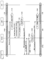
図1において、実線がユーザ信号(音声信号、データ信号等のユーザデータを示す信号)の送受信に用いられる経路を示し、破線が制御信号の送受信に用いられる経路を示す。すなわち、実線はUプレーン(ユーザプレーン,User Plane)のインタフェースを示し、破線はCプレーン(制御プレーン,Control Plane)のインタフェースを示す。Uプレーンのインタフェースを介してUプレーン経路が確立され、Cプレーンのインタフェースを介してCプレーン経路が確立される。
以上のインタフェースにおいては、原則として、3GPPに規定されるEPS(Evolved Packet System)のプロトコル構成が採用される。また、以上のプロトコル構成に定義されないインタフェースに関しては、第1基地局eNBと第2基地局PhNBとの間にX3インタフェースが存在し、第2基地局PhNBとユーザ装置UEとの間にPh-Uuインタフェースが存在する。なお、第2基地局PhNBとユーザ装置UEとの間にはCプレーンのインタフェースが存在しない。
無線通信システムCS内において、論理的な経路であるベアラ(Bearer)を介して信号が送受信される。ベアラは、必要に応じて確立され解放される動的な論理経路である。Uプレーンに関して、ユーザ装置UEと第1基地局eNB、またはユーザ装置UEと第2基地局PhNBとにデータ無線ベアラDRBが確立される。第1基地局eNBと第2基地局PhNBとにX3ベアラX3Bが確立される。第1基地局eNBとゲートウェイ装置GWとにS1ベアラが確立される。なお、ネットワークNW内にて確立されるベアラ(X3ベアラX3B,S1ベアラ等)は、GTP(GPRS (General Packet Radio Service) Tunneling Protocol)トンネルとも称される。
ユーザ装置UEは、ユーザ装置UEと第1基地局eNBとに確立されたデータ無線ベアラDRB及びS1ベアラを含む上位ベアラ(EPSベアラ)を介してインターネットINと通信可能であると共に、ユーザ装置UEと第2基地局PhNBとに確立されたデータ無線ベアラDRB、X3ベアラX3B、及びS1ベアラを含む上位ベアラを介してインターネットINと通信可能である。
無線通信システムCS内のノードは、それぞれ固有の識別情報を有する。識別情報には、そのノードのIPアドレス、TEID(トンネルエンドポイントID)、ネットワークアドレス等が含まれ得る。また、第1基地局eNBおよび第2基地局PhNBの識別情報には、その基地局が形成するセルCを識別するための物理セルID(Physical Cell ID)が含まれ得る。IPアドレスは、無線通信システムCS内でそのノードを一意に識別するアドレス値である。TEIDは、ノード間を論理的に接続するGTPトンネルの端点を識別する識別子である。ネットワークアドレスは、無線通信システムCSが複数のサブネットに分割されている場合に、そのノードが属するサブネットを識別するアドレス値である。無線通信システムCS内のノードは、他のノードの識別情報に基づいて他のノードを識別する。
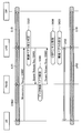
1(2). 第1基地局-第2基地局間のGTPトンネルの確立
図2を参照して、第1実施形態のGTPトンネルの確立動作の一例を説明する。図2の例では、当初、S1ベアラS1Bがゲートウェイ装置GWと第1基地局eNBとに確立され、S1ベアラS1Bと関連付けられたデータ無線ベアラDRB1が第1基地局eNBとユーザ装置UEとに確立されていると想定する(図3)。したがって、以上の想定において、ユーザ装置UEは、当初、無線接続中の第1基地局eNBのみを経由してユーザ信号の送受信を実行する。また、図3に示すように、Cプレーンに関しては、当初、ユーザ装置UEと第1基地局eNBとにシグナリング無線ベアラSRBが確立されていると想定する。
図2を参照して、第1実施形態のGTPトンネルの確立動作の一例を説明する。図2の例では、当初、S1ベアラS1Bがゲートウェイ装置GWと第1基地局eNBとに確立され、S1ベアラS1Bと関連付けられたデータ無線ベアラDRB1が第1基地局eNBとユーザ装置UEとに確立されていると想定する(図3)。したがって、以上の想定において、ユーザ装置UEは、当初、無線接続中の第1基地局eNBのみを経由してユーザ信号の送受信を実行する。また、図3に示すように、Cプレーンに関しては、当初、ユーザ装置UEと第1基地局eNBとにシグナリング無線ベアラSRBが確立されていると想定する。
ユーザ装置UEは、近傍の基地局が送信する電波の受信電力(受信品質)を測定して、無線接続中の第1基地局eNBに報告する。より具体的には、ユーザ装置UEは、近傍の基地局(eNB,PhNB)が送信する電波(参照信号)の受信電力(受信品質)を示す情報を搭載したMeasurement Reportメッセージ(測定報告メッセージ)を、Cプレーン経路(シグナリング無線ベアラSRB)を介して第1基地局eNBに送信する(S100)。特に、本例では、Measurement Reportメッセージが、第1基地局eNBからの受信電力を示す情報と第2基地局PhNBからの受信電力を示す情報とを含む。
第1基地局eNBは、ユーザ装置UEから送信されたMeasurement Reportメッセージを受信すると、ユーザ装置UEが第2基地局PhNBを経由してユーザ信号を送受信すべきか否か、すなわち、第1基地局eNBと第2基地局PhNBとにUプレーン経路(GTPトンネル)を確立すべきか否かを判定する(S120)。以上の判定は、例えば、「第2基地局PhNBからの電波の受信電力が、現在接続中の第1基地局eNBからの電波の受信電力よりも大きいか否か」という基準に基づいて実行される。本例では、ステップS120において、第1基地局eNBが、第1基地局eNBからの受信電力よりも第2基地局PhNBからの受信電力が大きいため、第1基地局eNBと第2基地局PhNBとにUプレーン経路を確立すべきと判定したと想定する。
ステップS120の判定後、第1基地局eNBは、第1基地局eNBと第2基地局PhNBとにUプレーン経路を確立することを指示するTunnel Setup Requestメッセージ(トンネル確立要求メッセージ)を第2基地局PhNBに送信する(S140)。Tunnel Setup Requestメッセージには、第1基地局eNBの識別情報が含まれる。第2基地局PhNBは、Tunnel Setup Requestメッセージを受信すると、Tunnel Setup Requestメッセージに含まれる第1基地局eNBの識別情報に基づいて第1基地局eNBに対する論理接続(上り論理接続)を確立した後、第2基地局PhNBの識別情報およびアクセス層設定情報(AS Config)を含むTunnel Setup Completeメッセージ(トンネル確立完了メッセージ)を第1基地局eNBに送信する(S160)。アクセス層設定情報には、ユーザ装置UEと第2基地局PhNBとが同期するために必要なランダムアクセスチャネル(Random Access Channel,RACH)のタイミング情報等が含まれる。第1基地局eNBは、Tunnel Setup Completeメッセージを受信すると、Tunnel Setup Completeメッセージに含まれる第2基地局PhNBの識別情報に基づいて第2基地局PhNBに対する論理接続(下り論理接続)を確立する。以上のように、第1基地局eNBが主導して、第1基地局eNBと第2基地局PhNBとのUプレーン経路(GTPトンネル)であるX3ベアラX3Bを確立する(S180)。
第1基地局eNBは、確立されたUプレーン経路(X3ベアラX3B)を、ゲートウェイ装置GWと第1基地局eNBとに確立されているS1ベアラS1Bに関連付ける(マッピングする)(S200)。図4は、ステップS200のマッピング後の論理経路を示す図であり、当初(図3)に確立されていたシグナリング無線ベアラSRB、データ無線ベアラDRB1、及びS1ベアラS1Bに加えて、X3ベアラX3Bが確立された状態を示す。
ステップS200が完了すると、第1基地局eNBは、第2基地局PhNBとユーザ装置UEとに新たなデータ無線ベアラDRB2を確立することを指示するRRC Connection Reconfigurationメッセージ(無線接続再設定メッセージ)を、現在接続中のユーザ装置UEに送信する(S220)。RRC Connection Reconfigurationメッセージには、ユーザ装置UEが第2基地局PhNBと無線接続するのに必要な情報(第2基地局PhNBの識別情報およびアクセス層設定情報)が含まれる。
ユーザ装置UEは、受信したRRC Connection Reconfigurationメッセージに従って、第2基地局PhNBへのデータ無線ベアラDRB2を確立する。より具体的には、受信したRRC Connection Reconfigurationメッセージに含まれる第2基地局PhNBの識別情報に基づいて、その第2基地局PhNBとの同期を実行した後、アクセス層設定情報を用いてその第2基地局PhNBにアクセスする(S240)。ユーザ装置UEが第2基地局PhNBへのアクセスに成功すると、新たなデータ無線ベアラDRB2の確立が完了する(S260)。すなわち、ユーザ装置UEは、RRC Connection Reconfigurationメッセージに従って第2基地局PhNBにアクセスすることにより、新たなデータ無線ベアラDRB2を確立する。
第2基地局PhNBは、確立された新たなデータ無線ベアラDRB2を、第1基地局eNBと第2基地局PhNBとに確立されたX3ベアラX3Bに関連付ける(マッピングする)(S280)。なお、第2基地局PhNBは、以上のマッピングが完了したことを示す制御信号をユーザ装置UEおよび第1基地局eNBのいずれか一方または双方に送信すると好適である。図5は、ステップS280のマッピング後の論理経路を示す図であり、新たなデータ無線ベアラDRB2、X3ベアラX3B、及びS1ベアラS1Bを経由して、ユーザ装置UEとゲートウェイ装置GWとが論理的に接続されたことを示す。
ステップS280の後、ユーザ装置UEは、新たなデータ無線ベアラDRB2が確立されたことを示すRRC Connection Reconfiguration Completeメッセージ(無線接続再設定完了メッセージ)を第1基地局eNBに送信する(S300)。なお、ユーザ装置UEは、新たなデータ無線ベアラDRB2の確立(S260)後に、RRC Connection Reconfiguration Completeメッセージを第1基地局eNBに送信してもよい。
第1基地局eNBは、新しく確立されたデータ無線ベアラDRB2とX3ベアラX3Bとが関連付けられた後(または、RRC Connection Reconfiguration Completeメッセージを受信した後)に、ユーザ装置UEと第1基地局とに確立されているデータ無線ベアラDRB1を解放することが可能である(S320)。なお、ステップS320が実行されず、双方のデータ無線ベアラDRB1が維持されてもよい。いずれの場合であっても、ユーザ装置UEと第1基地局とに確立されているシグナリング無線ベアラSRBは維持される。
以上に説明された動作により、第1基地局eNBと第2基地局PhNBとにUプレーン経路であるGTPトンネル(X3ベアラX3B)が確立され、第2基地局PhNBとユーザ装置UEとに新たなデータ無線ベアラDRB2が確立される。
1(3). 各要素の構成
1(3)-1. ユーザ装置の構成
図6は、第1実施形態に係るユーザ装置UEの構成を示すブロック図である。ユーザ装置UEは、無線通信部110と制御部120と記憶部130とを備える。音声・映像等を出力する出力装置およびユーザからの指示を受け付ける入力装置等の図示は便宜的に省略されている。
1(3)-1. ユーザ装置の構成
図6は、第1実施形態に係るユーザ装置UEの構成を示すブロック図である。ユーザ装置UEは、無線通信部110と制御部120と記憶部130とを備える。音声・映像等を出力する出力装置およびユーザからの指示を受け付ける入力装置等の図示は便宜的に省略されている。
無線通信部110は、第1基地局eNBおよび第2基地局PhNBと無線通信を実行するための要素であり、送受信アンテナと、無線信号(電波)を受信して電気信号に変換する受信回路と、制御信号、ユーザ信号等の電気信号を無線信号に変換して送信する送信回路とを含む。記憶部130は、通信制御に関する情報、特に自局を含む各ノードの識別情報および通信経路(Cプレーン経路、Uプレーン経路)のコンテキスト情報を記憶する。
制御部120は、通信制御部122とデータ送受信部124とを備える。通信制御部122は、ユーザ装置UEと各基地局(第1基地局eNB,第2基地局PhNB)との無線通信を制御する要素であり、シグナリング無線ベアラSRBを用いて、無線通信部110を介して各基地局と制御信号(制御メッセージ)を送受信する。すなわち、通信制御部122はCプレーン上の通信を実行する。例えば、前述したように、通信制御部122は、近傍の基地局からの電波の受信電力を測定してMeasurement Reportメッセージに搭載し、第1基地局eNBに送信する。また、通信制御部122は、第1基地局eNBが送信したRRC Connection Reconfigurationメッセージに基づいて第2基地局PhNBにアクセスし、データ無線ベアラDRB2をユーザ装置UEと第2基地局PhNBとに確立する。一方、データ送受信部124は、データ無線ベアラDRBを用いて、無線通信部110を介して各基地局とユーザ信号を送受信する。すなわち、データ送受信部124はUプレーン上の通信を実行する。
制御部120並びに制御部120に含まれる通信制御部122及びデータ送受信部124は、ユーザ装置UE内の不図示のCPU(Central Processing Unit)が、記憶部130に記憶されたコンピュータプログラムを実行し、そのコンピュータプログラムに従って機能することにより実現される機能ブロックである。
1(3)-2. 第1基地局の構成
図7は、第1実施形態に係る第1基地局eNBの構成を示すブロック図である。第1基地局eNBは、無線通信部210とネットワーク通信部220と記憶部230と制御部240とを備える。無線通信部210は、ユーザ装置UEと無線通信を実行するための要素であり、ユーザ装置UEの無線通信部110と同様の構成を有する。ネットワーク通信部220は、ネットワークNW内の他のノード(第2基地局PhNB、交換局MME、ゲートウェイ装置GW等)と通信を実行するための要素であり、他のノードと電気信号を送受信する。記憶部230は、通信制御に関する情報、特に自局を含む各ノードの識別情報および通信経路(Cプレーン経路、Uプレーン経路)のコンテキスト情報を記憶する。
図7は、第1実施形態に係る第1基地局eNBの構成を示すブロック図である。第1基地局eNBは、無線通信部210とネットワーク通信部220と記憶部230と制御部240とを備える。無線通信部210は、ユーザ装置UEと無線通信を実行するための要素であり、ユーザ装置UEの無線通信部110と同様の構成を有する。ネットワーク通信部220は、ネットワークNW内の他のノード(第2基地局PhNB、交換局MME、ゲートウェイ装置GW等)と通信を実行するための要素であり、他のノードと電気信号を送受信する。記憶部230は、通信制御に関する情報、特に自局を含む各ノードの識別情報および通信経路(Cプレーン経路、Uプレーン経路)のコンテキスト情報を記憶する。
制御部240は、ユーザ装置UE、第2基地局PhNB等の他ノードとの通信を制御する要素であり、特に、測定報告メッセージ受信部242と判定部244とUプレーン経路制御部246と無線接続設定部248とデータ送受信部250とを備える。以下、前述のように、測定報告メッセージ受信部242は、ユーザ装置UEが送信したMeasurement Reportメッセージを無線通信部210を介して受信し、判定部244に供給する。判定部244は、前述のステップS120におけるUプレーン経路(GTPトンネル)の確立判定を実行する。Uプレーン経路制御部246は、判定部244の判定に基づいて、Uプレーン経路(特に、X3ベアラX3B)の確立を制御する。また、Uプレーン経路制御部246は、1つのUプレーン経路と他のUプレーン経路とを関連付ける(マッピングする)。無線接続設定部248は、Cプレーン経路(シグナリング無線ベアラSRB)を用いてRRC Connection Reconfigurationメッセージを送信して、ユーザ装置UEの無線リソース制御(無線ベアラRBの確立・解放等)を実行する。データ送受信部250は、データ無線ベアラDRBを介してユーザ装置UEとユーザ信号を送受信(中継)すると共に、S1ベアラS1Bを介してゲートウェイ装置GWとユーザ信号を送受信(中継)する。以上から理解されるように、制御部240は、Cプレーン上およびUプレーン上の通信を実行する。
制御部240並びに制御部240に含まれる測定報告メッセージ受信部242、判定部244、Uプレーン経路制御部246、無線接続設定部248、およびデータ送受信部250は、第1基地局eNB内の不図示のCPUが、記憶部230に記憶されたコンピュータプログラムを実行し、そのコンピュータプログラムに従って機能することにより実現される機能ブロックである。
1(3)-3. 第2基地局の構成
図8は、第1実施形態に係る第2基地局PhNBの構成を示すブロック図である。第2基地局PhNBは、無線通信部310とネットワーク通信部320と記憶部330と制御部340とを備える。無線通信部310は、ユーザ装置UEと無線通信を実行するための要素であり、第1基地局eNBの無線通信部210と同様の構成を有する。ネットワーク通信部320は、第1基地局eNBと通信を実行するための要素であり、第1基地局eNBと電気信号を送受信する。記憶部330は、通信生業に関する情報、特に自局を含む各ノードの識別情報および通信経路(Cプレーン経路、Uプレーン経路)のコンテキスト情報を有する。
図8は、第1実施形態に係る第2基地局PhNBの構成を示すブロック図である。第2基地局PhNBは、無線通信部310とネットワーク通信部320と記憶部330と制御部340とを備える。無線通信部310は、ユーザ装置UEと無線通信を実行するための要素であり、第1基地局eNBの無線通信部210と同様の構成を有する。ネットワーク通信部320は、第1基地局eNBと通信を実行するための要素であり、第1基地局eNBと電気信号を送受信する。記憶部330は、通信生業に関する情報、特に自局を含む各ノードの識別情報および通信経路(Cプレーン経路、Uプレーン経路)のコンテキスト情報を有する。
制御部340は、Uプレーン経路処理部342とデータ送受信部344とを備える。前述のように、Uプレーン経路処理部342は、第1基地局eNBの制御(Tunnel Setup Requestメッセージ)に応じて、第1基地局eNBとの論理接続を確立した後、Tunnel Setup Completeメッセージを第1基地局eNBに送信する。また、Uプレーン経路処理部342は、1つのUプレーン経路と他のUプレーン経路とを関連付ける(マッピングする)。なお、制御部340はユーザ装置UEの無線リソース制御を実行しない。
データ送受信部344は、データ無線ベアラDRBを介してユーザ装置UEとユーザ信号を送受信(中継)すると共に、X3ベアラX3B及びS1ベアラS1Bを介して(すなわち、第1基地局eNB経由で)ゲートウェイ装置GWとユーザ信号を送受信(中継)する。すなわち、データ送受信部344はUプレーン上の通信を実行する。
制御部340並びに制御部340に含まれるUプレーン経路処理部342およびデータ送受信部344は、第2基地局PhNB内の不図示のCPUが、記憶部330に記憶されたコンピュータプログラムを実行し、そのコンピュータプログラムに従って機能することにより実現される機能ブロックである。
1(3)-4. 交換局の構成
図9は、第1実施形態に係る交換局MMEの構成を示すブロック図である。交換局MMEは、ネットワーク通信部410と記憶部420と制御部430とを備える。ネットワーク通信部410は、ネットワークNW内の他のノード(ゲートウェイ装置GW、第1基地局eNB等)と通信を実行するための要素であり、第1基地局eNBのネットワーク通信部220と同様の構成を有する。記憶部420は、通信制御に関する情報、特に自局を含む各ノードの識別情報および通信経路(Cプレーン経路、Uプレーン経路)のコンテキスト情報を記憶する。制御部430は、無線通信システムCSの通信制御を実行する通信制御部であり、他のノードと制御信号を送受信する。交換局MME(制御部430)は、Cプレーン上の通信を実行し、Uプレーン上の通信を実行しない。
図9は、第1実施形態に係る交換局MMEの構成を示すブロック図である。交換局MMEは、ネットワーク通信部410と記憶部420と制御部430とを備える。ネットワーク通信部410は、ネットワークNW内の他のノード(ゲートウェイ装置GW、第1基地局eNB等)と通信を実行するための要素であり、第1基地局eNBのネットワーク通信部220と同様の構成を有する。記憶部420は、通信制御に関する情報、特に自局を含む各ノードの識別情報および通信経路(Cプレーン経路、Uプレーン経路)のコンテキスト情報を記憶する。制御部430は、無線通信システムCSの通信制御を実行する通信制御部であり、他のノードと制御信号を送受信する。交換局MME(制御部430)は、Cプレーン上の通信を実行し、Uプレーン上の通信を実行しない。
制御部430は、交換局MME内の不図示のCPUが、記憶部420に記憶されたコンピュータプログラムを実行し、そのコンピュータプログラムに従って機能することにより実現される機能ブロックである。
1(3)-5. ゲートウェイ装置の構成
図10は、第1実施形態に係るゲートウェイ装置GWの構成を示すブロック図である。ゲートウェイ装置GWは、ネットワーク通信部510と外部ネットワーク通信部520と記憶部530と制御部540とを備える。ネットワーク通信部510は、ネットワークNW内の他のノード(第1基地局eNB、交換局MME等)と通信を実行するための要素であり、第1基地局eNBのネットワーク通信部220と同様の構成を有する。外部ネットワーク通信部520は、インターネットINと通信を実行するための要素であり、必要に応じてユーザ信号のプロトコル変換を実行する。記憶部530は、通信制御に関する情報、特に自局を含む各ノードの識別情報および通信経路(Cプレーン経路、Uプレーン経路)のコンテキスト情報を記憶する。
図10は、第1実施形態に係るゲートウェイ装置GWの構成を示すブロック図である。ゲートウェイ装置GWは、ネットワーク通信部510と外部ネットワーク通信部520と記憶部530と制御部540とを備える。ネットワーク通信部510は、ネットワークNW内の他のノード(第1基地局eNB、交換局MME等)と通信を実行するための要素であり、第1基地局eNBのネットワーク通信部220と同様の構成を有する。外部ネットワーク通信部520は、インターネットINと通信を実行するための要素であり、必要に応じてユーザ信号のプロトコル変換を実行する。記憶部530は、通信制御に関する情報、特に自局を含む各ノードの識別情報および通信経路(Cプレーン経路、Uプレーン経路)のコンテキスト情報を記憶する。
制御部540は、通信制御部542とデータ送受信部544とを備える。通信制御部542は、無線通信システムCSの通信制御を実行する要素であり、ネットワーク通信部510を介して交換局MMEと制御信号を送受信する。すなわち、通信制御部542は、ネットワーク通信部510を介してCプレーン上の通信を実行する。データ送受信部544は、データ送受信部544は、ネットワーク通信部510を介して受信したユーザ装置UE発のユーザ信号を、外部ネットワーク通信部520を介してインターネットIN(インターネットIN内の外部サーバ)に送信(中継)するとともに、外部ネットワーク通信部520を介してインターネットIN(インターネットIN内の外部サーバ)から受信したユーザ信号を、ネットワーク通信部510を介してユーザ装置UEに送信(中継)する。すなわち、データ送受信部524はUプレーン上の通信を実行する。
制御部540並びに制御部540に含まれる通信制御部542及びデータ送受信部544は、ゲートウェイ装置GW内の不図示のCPUが、記憶部530に記憶されたコンピュータプログラムを実行し、そのコンピュータプログラムに従って機能することにより実現される機能ブロックである。
1(4). 本実施形態の効果
以上に説明した第1実施形態によれば、第1基地局eNBと第2基地局PhNBとにUプレーン経路であるGTPトンネル(X3ベアラX3B)が確立され、ユーザ装置UEへのCプレーン経路を有さない第2基地局PhNBとユーザ装置UEとにUプレーン経路であるデータ無線ベアラDRB2が確立される。したがって、ユーザ装置UEは、ゲートウェイ装置GWと直接的に接続されない第2基地局PhNBを経由してユーザ信号を送受信することが可能となる。すなわち、ユーザ装置UEの無線リソース制御を実行しない(制御機能が限定的な)第2基地局PhNBを備える無線通信システムCSが実現される。
以上に説明した第1実施形態によれば、第1基地局eNBと第2基地局PhNBとにUプレーン経路であるGTPトンネル(X3ベアラX3B)が確立され、ユーザ装置UEへのCプレーン経路を有さない第2基地局PhNBとユーザ装置UEとにUプレーン経路であるデータ無線ベアラDRB2が確立される。したがって、ユーザ装置UEは、ゲートウェイ装置GWと直接的に接続されない第2基地局PhNBを経由してユーザ信号を送受信することが可能となる。すなわち、ユーザ装置UEの無線リソース制御を実行しない(制御機能が限定的な)第2基地局PhNBを備える無線通信システムCSが実現される。
第2実施形態
本発明の第2実施形態を以下に説明する。以下に例示する各実施形態において、作用、機能が第1実施形態と同等である要素については、以上の説明で参照した符号を流用して各々の説明を適宜に省略する。
本発明の第2実施形態を以下に説明する。以下に例示する各実施形態において、作用、機能が第1実施形態と同等である要素については、以上の説明で参照した符号を流用して各々の説明を適宜に省略する。
第1実施形態では、第1基地局eNBと第2基地局PhNBとにUプレーン経路が確立される。第2実施形態では、第1基地局eNBと第2基地局PhNBとに確立されたUプレーン経路が解放され得る。
2(1). 第1基地局-第2基地局間のGTPトンネルの解放
図11を参照して、第2実施形態のGTPトンネルの解放動作の一例を説明する。図11の例では、当初、S1ベアラS1Bがゲートウェイ装置GWと第1基地局eNBとに確立され、S1ベアラS1Bと関連付けられたX3ベアラX3Bが第1基地局eNBと第2基地局PhNBとに確立され、X3ベアラX3Bと関連付けられたデータ無線ベアラDRB2が第2基地局PhNBとユーザ装置UEとに確立されていると想定する(図12)。すなわち、図11の例は、第1実施形態において第1基地局eNBと第2基地局PhNBとにGTPトンネルが確立され、ユーザ装置UEと第1基地局eNBとに確立されていたデータ無線ベアラDRB1が解放された後の状態であると表現され得る。したがって、以上の想定において、ユーザ装置UEは、当初、無線接続中の第2基地局PhNBを経由してユーザ信号の送受信を実行する。また、図12に示すように、Cプレーンに関しては、当初、ユーザ装置UEと第1基地局eNBとにシグナリング無線ベアラSRBが確立されていると想定する。
図11を参照して、第2実施形態のGTPトンネルの解放動作の一例を説明する。図11の例では、当初、S1ベアラS1Bがゲートウェイ装置GWと第1基地局eNBとに確立され、S1ベアラS1Bと関連付けられたX3ベアラX3Bが第1基地局eNBと第2基地局PhNBとに確立され、X3ベアラX3Bと関連付けられたデータ無線ベアラDRB2が第2基地局PhNBとユーザ装置UEとに確立されていると想定する(図12)。すなわち、図11の例は、第1実施形態において第1基地局eNBと第2基地局PhNBとにGTPトンネルが確立され、ユーザ装置UEと第1基地局eNBとに確立されていたデータ無線ベアラDRB1が解放された後の状態であると表現され得る。したがって、以上の想定において、ユーザ装置UEは、当初、無線接続中の第2基地局PhNBを経由してユーザ信号の送受信を実行する。また、図12に示すように、Cプレーンに関しては、当初、ユーザ装置UEと第1基地局eNBとにシグナリング無線ベアラSRBが確立されていると想定する。
ユーザ装置UEは、第1実施形態と同様に、近傍の基地局(eNB,PhNB)が送信する電波(参照信号)の受信電力(受信品質)を示す情報を搭載したMeasurement Reportメッセージを、Cプレーン経路を介して第1基地局eNBに送信する(S500)。第1基地局eNB(判定部244)は、ユーザ装置UEから送信されたMeasurement Reportメッセージを受信すると、ユーザ装置UEと第1基地局eNBとにUプレーン経路(データ無線ベアラDRB1)を確立すべきか否か(ひいては、第1基地局eNBと第2基地局PhNBとに確立されたUプレーン経路(GTPトンネル)を解放すべきか否か)を判定する(S520)。以上の判定は、例えば、第1実施形態と同様の基準に基づいて実行される。本例では、ステップS520において、第1基地局eNB(判定部244)が、第2基地局PhNBからの受信電力よりも第1基地局eNBからの受信電力が大きいため、ユーザ装置UEと第1基地局eNBとにデータ無線ベアラDRB1を確立すべきと判定したと想定する。
ステップS520の判定後、第1基地局eNB(Uプレーン経路制御部246)は、現在ユーザ装置UEと第2基地局PhNBとに確立されているデータ無線ベアラDRB2を解放することを指示するBearer Release Requestメッセージ(ベアラ解放要求メッセージ)を、第2基地局PhNBに送信する(S540)。第2基地局PhNB(Uプレーン経路処理部342)は、受信したBearer Release Requestメッセージに基づいて、現在確立されているデータ無線ベアラDRB2を解放する(S560)。データ無線ベアラDRB2の解放に伴い、データ無線ベアラDRB2とX3ベアラX3Bとの関連付けが切り離される(disassociated)。ステップS560の後、第2基地局PhNB(Uプレーン経路処理部342)は、データ無線ベアラDRB2が解放されたことを示すBearer Release Responseメッセージ(ベアラ解放応答メッセージ)を、第1基地局eNBに送信する(S580)。第1基地局eNB(Uプレーン経路制御部246)は、Bearer Release Responseメッセージを受信すると、X3ベアラX3B(GTPトンネル)を解放する(S600)。X3ベアラX3Bの解放に伴い、X3ベアラX3BとS1ベアラS1Bとの関連付けが切り離される。
ステップS600のGTPトンネル解放後、第1基地局eNBは、ユーザ装置UEと第1基地局eNBとにデータ無線ベアラDRB1を設定(確立)する(S620)。具体的には、図13に示すように、第1基地局eNBのUプレーン経路制御部246は、ユーザ装置UEと第1基地局eNBとの間にUプレーン経路(データ無線ベアラDRB)が既に存在するか否かを判定する(S622)。データ無線ベアラDRBが存在する場合(S622:YES)、第1基地局eNBは、その既存のデータ無線ベアラDRBを、ゲートウェイ装置GWと第1基地局eNBとに確立されているS1ベアラS1Bに関連付ける(マッピングする)(S624)。他方、データ無線ベアラDRBが存在しない場合(S622:NO)、第1基地局eNBのUプレーン経路制御部246は、無線接続設定部248を制御して、ユーザ装置UEと第1基地局eNBとに新たなデータ無線ベアラDRBを確立することを指示するRRC Connection Reconfigurationメッセージをユーザ装置UEに送信させる(S626)。Uプレーン経路制御部246は、確立された新たなデータ無線ベアラDRBを、S1ベアラS1Bに関連付ける(マッピングする)(S628)。ステップS620において、以上のようにしてユーザ装置UEと第1基地局eNBとにデータ無線ベアラDRB1が確立される。
2(2). 第2実施形態の変形例
以上の第2実施形態の構成において、ステップS540からS600までの動作(データ無線ベアラDRB2およびX3ベアラX3Bの解放)がスキップされてもよい。すなわち、既に確立されているデータ無線ベアラDRB2およびX3ベアラX3Bが維持されたまま、ユーザ装置UEと第1基地局eNBとにデータ無線ベアラDRB1が設定されてもよい。
以上の第2実施形態の構成において、ステップS540からS600までの動作(データ無線ベアラDRB2およびX3ベアラX3Bの解放)がスキップされてもよい。すなわち、既に確立されているデータ無線ベアラDRB2およびX3ベアラX3Bが維持されたまま、ユーザ装置UEと第1基地局eNBとにデータ無線ベアラDRB1が設定されてもよい。
2(3). 本実施形態の効果
以上に説明した第2実施形態によれば、第1基地局eNBと第2基地局PhNBとに確立されたUプレーン経路であるGTPトンネル(X3ベアラX3B)が解放され得ると共に、ユーザ装置UEと第1基地局eNBとにデータ無線ベアラDRB1が確立される。したがって、当初に第2基地局PhNBを経由して無線通信していたユーザ装置UEが、第1基地局eNBを経由してユーザ信号を送受信することが可能となる。すなわち、ユーザ装置UEの無線リソース制御を実行しない(制御機能が限定的な)第2基地局PhNBを備える無線通信システムCSが実現される。
以上に説明した第2実施形態によれば、第1基地局eNBと第2基地局PhNBとに確立されたUプレーン経路であるGTPトンネル(X3ベアラX3B)が解放され得ると共に、ユーザ装置UEと第1基地局eNBとにデータ無線ベアラDRB1が確立される。したがって、当初に第2基地局PhNBを経由して無線通信していたユーザ装置UEが、第1基地局eNBを経由してユーザ信号を送受信することが可能となる。すなわち、ユーザ装置UEの無線リソース制御を実行しない(制御機能が限定的な)第2基地局PhNBを備える無線通信システムCSが実現される。
第3実施形態
以上の実施形態では、第1基地局eNBが、Uプレーン経路の確立および解放を実行すべきか否かを判定する判定部を備える。第3実施形態で、以上のような判定部を、交換局MMEが備える。
以上の実施形態では、第1基地局eNBが、Uプレーン経路の確立および解放を実行すべきか否かを判定する判定部を備える。第3実施形態で、以上のような判定部を、交換局MMEが備える。
3(1)-1. 第1基地局の構成
図14は、第3実施形態に係る第1基地局eNBの構成を示すブロック図である。第1基地局eNB(制御部240)が備える転送部243は、測定報告メッセージ受信部242が受信したMeasurement Reportメッセージを、ネットワーク通信部220を介して交換局へ転送する機能ブロックである。なお、第1基地局eNBの制御部240は、判定部244を備えない。
図14は、第3実施形態に係る第1基地局eNBの構成を示すブロック図である。第1基地局eNB(制御部240)が備える転送部243は、測定報告メッセージ受信部242が受信したMeasurement Reportメッセージを、ネットワーク通信部220を介して交換局へ転送する機能ブロックである。なお、第1基地局eNBの制御部240は、判定部244を備えない。
3(1)-2. 交換局の構成
図15は、第3実施形態に係る交換局MMEの構成を示すブロック図である。交換局MMEの制御部430は、判定部432と判定結果送信部434とを備える。判定部432は、第1実施形態および第2実施形態の第1基地局eNBが備える判定部244と同様の機能ブロックである。判定部432は、第1基地局eNBから転送されたMeasurement Reportメッセージに基づいて、第1基地局eNBと第2基地局PhNBとにX3ベアラX3Bを確立すべきか否かを判定する。また、判定部432は、第1基地局eNBから転送されたMeasurement Reportメッセージに基づいて、ユーザ装置UEと第1基地局eNBとにデータ無線ベアラDRB1を確立すべきか否かを判定する。判定結果送信部434は、以上の判定部432による判定結果を、ネットワーク通信部410を介して第1基地局eNB(Uプレーン経路制御部246)に送信する機能ブロックである。
図15は、第3実施形態に係る交換局MMEの構成を示すブロック図である。交換局MMEの制御部430は、判定部432と判定結果送信部434とを備える。判定部432は、第1実施形態および第2実施形態の第1基地局eNBが備える判定部244と同様の機能ブロックである。判定部432は、第1基地局eNBから転送されたMeasurement Reportメッセージに基づいて、第1基地局eNBと第2基地局PhNBとにX3ベアラX3Bを確立すべきか否かを判定する。また、判定部432は、第1基地局eNBから転送されたMeasurement Reportメッセージに基づいて、ユーザ装置UEと第1基地局eNBとにデータ無線ベアラDRB1を確立すべきか否かを判定する。判定結果送信部434は、以上の判定部432による判定結果を、ネットワーク通信部410を介して第1基地局eNB(Uプレーン経路制御部246)に送信する機能ブロックである。
3(2). 第1基地局-第2基地局間のGTPトンネルの確立
図16を参照して、第3実施形態のGTPトンネルの確立動作の一例を説明する。当初の想定は、第1実施形態(特に図3)と同様である。ユーザ装置UEは、第1実施形態と同様にして、Measurement Reportメッセージを第1基地局eNBに送信する(S100)。第1基地局eNBは、ユーザ装置UEからMeasurement Reportメッセージを受信すると、交換局MMEに転送する(S110)。交換局MME(判定部432)は、第1基地局eNBから転送されたMeasurement Reportメッセージを受信すると、第1実施形態の第1基地局eNBと同様、ユーザ装置UEが第2基地局PhNBを経由してユーザ信号を送受信すべきか否か、すなわち、第1基地局eNBと第2基地局PhNBとにUプレーン経路(GTPトンネル)を確立すべきか否かを判定する(S120)。交換局MME(判定結果送信部434)は、ステップS120における判定結果を第1基地局eNBに送信する(S130)。本例では、以上の判定結果が、第1基地局eNBと第2基地局PhNBとにUプレーン経路を確立すべきとの判定を示すと想定する。第1基地局eNB(Uプレーン経路制御部246)は、受信した判定結果に基づき、Tunnel Setup Requestメッセージを第2基地局PhNBに送信する(S140)。以降の動作は、第1実施形態(図2)と同様である。
図16を参照して、第3実施形態のGTPトンネルの確立動作の一例を説明する。当初の想定は、第1実施形態(特に図3)と同様である。ユーザ装置UEは、第1実施形態と同様にして、Measurement Reportメッセージを第1基地局eNBに送信する(S100)。第1基地局eNBは、ユーザ装置UEからMeasurement Reportメッセージを受信すると、交換局MMEに転送する(S110)。交換局MME(判定部432)は、第1基地局eNBから転送されたMeasurement Reportメッセージを受信すると、第1実施形態の第1基地局eNBと同様、ユーザ装置UEが第2基地局PhNBを経由してユーザ信号を送受信すべきか否か、すなわち、第1基地局eNBと第2基地局PhNBとにUプレーン経路(GTPトンネル)を確立すべきか否かを判定する(S120)。交換局MME(判定結果送信部434)は、ステップS120における判定結果を第1基地局eNBに送信する(S130)。本例では、以上の判定結果が、第1基地局eNBと第2基地局PhNBとにUプレーン経路を確立すべきとの判定を示すと想定する。第1基地局eNB(Uプレーン経路制御部246)は、受信した判定結果に基づき、Tunnel Setup Requestメッセージを第2基地局PhNBに送信する(S140)。以降の動作は、第1実施形態(図2)と同様である。
3(3). 第1基地局-第2基地局間のGTPトンネルの解放
図17を参照して、第3実施形態のGTPトンネルの解放動作の一例を説明する。当初の想定は、第2実施形態(特に図12)と同様である。ユーザ装置UEは、第2実施形態と同様にして、Measurement Reportメッセージを第1基地局eNBに送信する(S500)。第1基地局eNBは、ユーザ装置UEからMeasurement Reportメッセージを受信すると、交換局MMEに転送する(S510)。交換局MME(判定部432)は、第1基地局eNBから転送されたMeasurement Reportメッセージを受信すると、第2実施形態の第1基地局eNBと同様、ユーザ装置UEと第1基地局eNBとにUプレーン経路を確立すべきか否か(ひいては、第1基地局eNBと第2基地局PhNBとに確立されたUプレーン経路を解放すべきか否か)を判定する(S520)。交換局MME(判定結果送信部434)は、ステップS520における判定結果を第1基地局eNBに送信する(S530)。本例では、以上の判定結果が、ユーザ装置UEと第1基地局eNBとにデータ無線ベアラDRB1を確立すべきとの判定を示すと想定する。第1基地局eNB(Uプレーン経路制御部246)は、受信した判定結果に基づき、Bearer Release Requestメッセージを第2基地局PhNBに送信する(S540)。以降の動作は、第2実施形態(図11)と同様である。第2実施形態と同様、ステップS540からS600までの動作(データ無線ベアラDRB2およびX3ベアラX3Bの解放)がスキップされてもよい。
図17を参照して、第3実施形態のGTPトンネルの解放動作の一例を説明する。当初の想定は、第2実施形態(特に図12)と同様である。ユーザ装置UEは、第2実施形態と同様にして、Measurement Reportメッセージを第1基地局eNBに送信する(S500)。第1基地局eNBは、ユーザ装置UEからMeasurement Reportメッセージを受信すると、交換局MMEに転送する(S510)。交換局MME(判定部432)は、第1基地局eNBから転送されたMeasurement Reportメッセージを受信すると、第2実施形態の第1基地局eNBと同様、ユーザ装置UEと第1基地局eNBとにUプレーン経路を確立すべきか否か(ひいては、第1基地局eNBと第2基地局PhNBとに確立されたUプレーン経路を解放すべきか否か)を判定する(S520)。交換局MME(判定結果送信部434)は、ステップS520における判定結果を第1基地局eNBに送信する(S530)。本例では、以上の判定結果が、ユーザ装置UEと第1基地局eNBとにデータ無線ベアラDRB1を確立すべきとの判定を示すと想定する。第1基地局eNB(Uプレーン経路制御部246)は、受信した判定結果に基づき、Bearer Release Requestメッセージを第2基地局PhNBに送信する(S540)。以降の動作は、第2実施形態(図11)と同様である。第2実施形態と同様、ステップS540からS600までの動作(データ無線ベアラDRB2およびX3ベアラX3Bの解放)がスキップされてもよい。
3(4). 第3実施形態の効果
以上に説明した第3実施形態によれば、第1実施形態および第2実施形態と同様の作用および効果が奏される。また、交換局MMEがUプレーン経路を確立・解放すべきか否かを判定するので、第1基地局eNBが判定を実行する構成と比較して、第1基地局eNBの処理負荷がより低減される。
以上に説明した第3実施形態によれば、第1実施形態および第2実施形態と同様の作用および効果が奏される。また、交換局MMEがUプレーン経路を確立・解放すべきか否かを判定するので、第1基地局eNBが判定を実行する構成と比較して、第1基地局eNBの処理負荷がより低減される。
変形例
以上の実施の形態は多様に変形される。具体的な変形の態様を以下に例示する。以上の実施の形態および以下の例示から任意に選択された2以上の態様は、相互に矛盾しない限り適宜に併合され得る。
以上の実施の形態は多様に変形される。具体的な変形の態様を以下に例示する。以上の実施の形態および以下の例示から任意に選択された2以上の態様は、相互に矛盾しない限り適宜に併合され得る。
4(1). 変形例1
以上の実施形態では、交換局MMEと第2基地局PhNBとが直接に接続されない。しかしながら、図18に示すように、交換局MMEと第2基地局PhNBとの間にCプレーンのインタフェース(S1-MMEインタフェース)が存在する構成も採用可能である。また、無線通信システムCSに含まれる複数の第2基地局PhNBのうち、一部の第2基地局PhNBが図1のように交換局MMEと接続せず、他の一部の第2基地局PhNBが図2のように交換局MMEと接続する構成も採用可能である。
以上の実施形態では、交換局MMEと第2基地局PhNBとが直接に接続されない。しかしながら、図18に示すように、交換局MMEと第2基地局PhNBとの間にCプレーンのインタフェース(S1-MMEインタフェース)が存在する構成も採用可能である。また、無線通信システムCSに含まれる複数の第2基地局PhNBのうち、一部の第2基地局PhNBが図1のように交換局MMEと接続せず、他の一部の第2基地局PhNBが図2のように交換局MMEと接続する構成も採用可能である。
4(2). 変形例2
以上の実施形態では、ゲートウェイ装置GWが単一の装置であるように記載される。しかしながら、ゲートウェイ装置GWが、複数の装置、例えば、LTE/SAE規格に規定されるサービングゲートウェイ(Serving Gateway)およびPDNゲートウェイ(Packet Data Network Gateway)により構成されてもよい。
以上の実施形態では、ゲートウェイ装置GWが単一の装置であるように記載される。しかしながら、ゲートウェイ装置GWが、複数の装置、例えば、LTE/SAE規格に規定されるサービングゲートウェイ(Serving Gateway)およびPDNゲートウェイ(Packet Data Network Gateway)により構成されてもよい。
4(3). 変形例3
以上の実施形態では、各基地局がその周囲に形成するセルC(電波が有効に到達する範囲)の大きさは任意である。例えば、第1基地局eNBの無線送信能力(平均送信電力、最大送信電力等)が第2基地局PhNBの無線送信能力と比較して大きく、第1基地局eNBが形成するセル(マクロセルC1)の大きさが第2基地局PhNBが形成するセル(スモールセルC2)の大きさを上回る構成が採用され得る。以上の構成においては、例えば、図19に示すように、スモールセルC2がマクロセルC1の内部に重層的に形成される(オーバレイされる)と好適である(作図の便宜上、マクロセルC1が示される平面とスモールセルC2が示される平面とが相違しているが、実際には、同一の平面(地表等)上にマクロセルC1とスモールセルC2とが重畳され得る)。一方で、第1基地局eNBと第2基地局PhNBとが略同一の大きさのセルCを形成する構成も採用可能である。
以上の実施形態では、各基地局がその周囲に形成するセルC(電波が有効に到達する範囲)の大きさは任意である。例えば、第1基地局eNBの無線送信能力(平均送信電力、最大送信電力等)が第2基地局PhNBの無線送信能力と比較して大きく、第1基地局eNBが形成するセル(マクロセルC1)の大きさが第2基地局PhNBが形成するセル(スモールセルC2)の大きさを上回る構成が採用され得る。以上の構成においては、例えば、図19に示すように、スモールセルC2がマクロセルC1の内部に重層的に形成される(オーバレイされる)と好適である(作図の便宜上、マクロセルC1が示される平面とスモールセルC2が示される平面とが相違しているが、実際には、同一の平面(地表等)上にマクロセルC1とスモールセルC2とが重畳され得る)。一方で、第1基地局eNBと第2基地局PhNBとが略同一の大きさのセルCを形成する構成も採用可能である。
4(4). 変形例4
第1基地局eNBが送信する電波の周波数帯と第2基地局PhNBが送信する電波の周波数帯とが相違する構成も採用可能である。例えば、第1基地局eNBが第1周波数帯(例えば、2GHz帯)を用いて無線通信し、第2基地局PhNBが第1周波数帯より高い第2周波数帯(例えば、3.5GHz帯)を用いて無線通信する構成を想定する。周波数が高いほど伝搬損失が大きくなることから、第2周波数帯を用いた無線通信よりも第1周波数帯を用いた無線通信の方が安定性が高い場合が多い。以上の実施形態にて説明した通り、ユーザ装置UEとの制御信号(制御メッセージ)の送受信(Cプレーンの通信)は第1基地局eNBが実行する。したがって、この変形例の構成を採用すれば、より安定性の高い第1周波数帯にて制御信号の送受信(Cプレーンの通信)が実行されるので、より確実なユーザ装置UEの制御が実現され得る。
第1基地局eNBが送信する電波の周波数帯と第2基地局PhNBが送信する電波の周波数帯とが相違する構成も採用可能である。例えば、第1基地局eNBが第1周波数帯(例えば、2GHz帯)を用いて無線通信し、第2基地局PhNBが第1周波数帯より高い第2周波数帯(例えば、3.5GHz帯)を用いて無線通信する構成を想定する。周波数が高いほど伝搬損失が大きくなることから、第2周波数帯を用いた無線通信よりも第1周波数帯を用いた無線通信の方が安定性が高い場合が多い。以上の実施形態にて説明した通り、ユーザ装置UEとの制御信号(制御メッセージ)の送受信(Cプレーンの通信)は第1基地局eNBが実行する。したがって、この変形例の構成を採用すれば、より安定性の高い第1周波数帯にて制御信号の送受信(Cプレーンの通信)が実行されるので、より確実なユーザ装置UEの制御が実現され得る。
4(5). 変形例5
以上の実施形態では、第2基地局PhNBはユーザ装置UEと制御信号を送受信しない。しかしながら、第2基地局PhNBが下位レイヤ(例えば、L1レイヤ,L2レイヤ)の制御信号を送受信可能な構成も採用可能である。以上の構成においても、第2基地局PhNBは、無線リソース制御に関する信号(RRCレイヤの制御信号)を送受信しない。
以上の実施形態では、第2基地局PhNBはユーザ装置UEと制御信号を送受信しない。しかしながら、第2基地局PhNBが下位レイヤ(例えば、L1レイヤ,L2レイヤ)の制御信号を送受信可能な構成も採用可能である。以上の構成においても、第2基地局PhNBは、無線リソース制御に関する信号(RRCレイヤの制御信号)を送受信しない。
4(6). 変形例6
ユーザ装置UEは、第1基地局eNBおよび第2基地局PhNBと無線通信が可能な任意の装置である。ユーザ装置UEは、例えば、フィーチャーフォンまたはスマートフォン等の携帯電話端末でもよく、デスクトップ型パーソナルコンピュータでもよく、ノート型パーソナルコンピュータでもよく、UMPC(Ultra-Mobile Personal Computer)でもよく、携帯用ゲーム機でもよく、その他の無線端末でもよい。
ユーザ装置UEは、第1基地局eNBおよび第2基地局PhNBと無線通信が可能な任意の装置である。ユーザ装置UEは、例えば、フィーチャーフォンまたはスマートフォン等の携帯電話端末でもよく、デスクトップ型パーソナルコンピュータでもよく、ノート型パーソナルコンピュータでもよく、UMPC(Ultra-Mobile Personal Computer)でもよく、携帯用ゲーム機でもよく、その他の無線端末でもよい。
4(7). 変形例7
無線通信システムCS内の各要素(ユーザ装置UE、第1基地局eNB、第2基地局PhNB、交換局MME、ゲートウェイ装置GW)においてCPUが実行する各機能は、CPUの代わりに、ハードウェアで実行してもよいし、例えばFPGA(Field Programmable Gate Array)、DSP(Digital Signal Processor)等のプログラマブルロジックデバイスで実行してもよい。
無線通信システムCS内の各要素(ユーザ装置UE、第1基地局eNB、第2基地局PhNB、交換局MME、ゲートウェイ装置GW)においてCPUが実行する各機能は、CPUの代わりに、ハードウェアで実行してもよいし、例えばFPGA(Field Programmable Gate Array)、DSP(Digital Signal Processor)等のプログラマブルロジックデバイスで実行してもよい。
UE……ユーザ装置、110……無線通信部、120……制御部、122……通信制御部、124……データ送受信部、130……記憶部、eNB……第1基地局、210……無線通信部、220……ネットワーク通信部、230……記憶部、240……制御部、242……測定報告メッセージ受信部、243……転送部、244……判定部、246……Uプレーン経路制御部、248……無線接続設定部、250……データ送受信部、PhNB……第2基地局、310……無線通信部、320……ネットワーク通信部、330……記憶部、340……制御部、342……Uプレーン経路処理部、344……データ送受信部、MME……交換局、410……ネットワーク通信部、420……記憶部、430……制御部、432……判定部、434……判定結果送信部、GW……ゲートウェイ装置、510……ネットワーク通信部、520……外部ネットワーク通信部、524……データ送受信部、530……記憶部、540……制御部、542……通信制御部、544……データ送受信部、C(C1,C2)……セル、CS……無線通信システム、DRB……データ無線ベアラ、IN……インターネット、NW……ネットワーク、RB……無線ベアラ、S1B……S1ベアラ、SRB……シグナリング無線ベアラ、X3B……X3ベアラ。
Claims (11)
- ユーザ装置と、
前記ユーザ装置の無線リソース制御を、制御プレーン経路を介して実行可能である第1基地局と、
前記ユーザ装置の無線リソース制御を実行しない第2基地局と
を含む複数の基地局と、
ゲートウェイ装置とを備え、
前記第1基地局は、
前記ユーザ装置から送信される、前記基地局が送信する電波に関する測定報告メッセージを受信する測定報告メッセージ受信部と、
前記ユーザ装置と前記第1基地局とに制御プレーン経路及び第1ユーザプレーン経路が確立され、前記第1基地局と前記ゲートウェイ装置とに第2ユーザプレーン経路が確立されている場合に、前記第1基地局と前記第2基地局とに第3ユーザプレーン経路を確立すべきか否かを前記測定報告メッセージに基づいて判定する判定部と、
前記第3ユーザプレーン経路を確立すべきと前記判定部が判定したときに、前記第1基地局と前記第2基地局とに前記第3ユーザプレーン経路を確立し、確立された前記第3ユーザプレーン経路を前記第2ユーザプレーン経路に関連付けるユーザプレーン経路制御部と、
前記ユーザ装置と前記第2基地局とに第4ユーザプレーン経路を確立することを指示する無線接続再設定メッセージを、前記ユーザ装置に送信する無線接続設定部とを備え、
前記第2基地局は、
前記ユーザ装置が確立した前記第4ユーザプレーン経路を、前記第3ユーザプレーン経路に関連付けるユーザプレーン経路処理部を備える
無線通信システム。 - ユーザ装置と、
前記ユーザ装置の無線リソース制御を、制御プレーン経路を介して実行可能である第1基地局と、
前記ユーザ装置の無線リソース制御を実行しない第2基地局と
を含む複数の基地局と、
交換局と、
ゲートウェイ装置とを備え、
前記第1基地局は、
前記ユーザ装置から送信される、前記基地局からの電波に関する測定報告メッセージを受信する測定報告メッセージ受信部と、
前記測定報告メッセージを前記交換局に転送する転送部とを備え、
前記交換局は、
前記ユーザ装置と前記第1基地局とに制御プレーン経路及び第1ユーザプレーン経路が確立され、前記第1基地局と前記ゲートウェイ装置とに第2ユーザプレーン経路が確立されている場合に、前記第1基地局と前記第2基地局とに第3ユーザプレーン経路を確立すべきか否かを前記測定報告メッセージに基づいて判定する判定部と、
前記判定部の判定結果を前記第1基地局に送信する判定結果送信部とを備え、
前記第1基地局は、さらに、
前記判定結果が前記第3ユーザプレーン経路を確立すべきとの判定を示すときに、前記第1基地局と前記第2基地局とに前記第3ユーザプレーン経路を確立し、確立された前記第3ユーザプレーン経路を前記第2ユーザプレーン経路に関連付けるユーザプレーン経路制御部と、
前記ユーザ装置と前記第2基地局とに第4ユーザプレーン経路を確立することを指示する無線接続再設定メッセージを、前記ユーザ装置に送信する無線接続設定部とを備え、
前記第2基地局は、
前記ユーザ装置が確立した前記第4ユーザプレーン経路を、前記第3ユーザプレーン経路に関連付けるユーザプレーン経路処理部を備える
無線通信システム。 - 前記第1基地局の前記ユーザプレーン経路制御部は、
前記第3ユーザプレーン経路と前記第4ユーザプレーン経路とが関連付けられた後に前記第1ユーザプレーン経路を解放する
請求項1に記載の無線通信システム。 - 前記第1基地局の前記ユーザプレーン経路制御部は、
前記第1基地局の識別情報を含み、前記第3ユーザプレーン経路を確立することを要求する経路確立要求メッセージを第2基地局に送信し、
前記第2基地局の前記ユーザプレーン経路処理部は、
前記経路確立要求メッセージに応じて、前記第2基地局の識別情報を含む経路確立応答メッセージを送信し、
前記第1基地局の前記無線接続設定部は、
前記第2基地局の前記識別情報を含む前記無線接続再設定メッセージを前記ユーザ装置に送信し、
前記ユーザ装置は、
前記無線接続再設定メッセージに基づいて前記第2基地局にアクセスすることにより前記第4ユーザプレーン経路を確立する通信制御部を備える
請求項1に記載の無線通信システム。 - ユーザ装置と、
前記ユーザ装置の無線リソース制御を、制御プレーン経路を介して実行可能である第1基地局と、
前記ユーザ装置の無線リソース制御を実行しない第2基地局と
を含む複数の基地局と、
ゲートウェイ装置とを備え、
前記第1基地局は、
前記ユーザ装置から送信される、前記基地局が送信する電波に関する測定報告メッセージを受信する測定報告メッセージ受信部と、
前記ユーザ装置と前記第1基地局とに制御プレーン経路が確立され、前記ゲートウェイ装置と前記第1基地局とに第2ユーザプレーン経路が確立され、前記第1基地局と前記第2基地局とに第3ユーザプレーン経路が前記第2ユーザプレーン経路と関連付けて確立され、前記第2基地局と前記ユーザ装置とに第4ユーザプレーン経路が前記第3ユーザプレーン経路と関連付けて確立されている場合に、前記ユーザ装置と前記第1基地局とに第1ユーザプレーン経路を確立すべきか否かを前記測定報告メッセージに基づいて判定する判定部と、
前記第1ユーザプレーン経路を確立すべきと前記判定部が判定した場合に、前記ユーザ装置と前記第1基地局とに前記第1ユーザプレーン経路を確立するユーザプレーン経路制御部とを備える
無線通信システム。 - 前記第1基地局の前記ユーザプレーン経路制御部は、
前記第1ユーザプレーン経路を確立すべきと前記判定部が判定したときに、前記第4ユーザプレーン経路を解放することを要求する経路解放要求メッセージを前記第2基地局に送信し、
前記第2基地局は、
前記経路解放要求メッセージに基づいて前記第4ユーザプレーン経路を解放し、前記第4ユーザプレーン経路の解放後に、経路解放応答メッセージを前記第1基地局に送信するユーザプレーン経路処理部を備え、
前記第1基地局の前記ユーザプレーン経路制御部は、
前記経路解放応答メッセージを受信すると、前記第3ユーザプレーン経路を解放する
請求項5に記載の無線通信システム。 - ユーザ装置と、
前記ユーザ装置の無線リソース制御を、制御プレーン経路を介して実行可能である第1基地局と、
前記ユーザ装置の無線リソース制御を実行しない第2基地局と
を含む複数の基地局と、
交換局と、
ゲートウェイ装置とを備え、
前記第1基地局は、
前記ユーザ装置から送信される、前記基地局が送信する電波に関する測定報告メッセージを受信する測定報告メッセージ受信部と、
前記測定報告メッセージを前記交換局に転送する転送部とを備え、
前記交換局は、
前記ユーザ装置と前記第1基地局とに制御プレーン経路が確立され、前記ゲートウェイ装置と前記第1基地局とに第2ユーザプレーン経路が確立され、前記第1基地局と前記第2基地局とに第3ユーザプレーン経路が前記第2ユーザプレーン経路と関連付けて確立され、前記第2基地局と前記ユーザ装置とに第4ユーザプレーン経路が前記第3ユーザプレーン経路と関連付けて確立されている場合に、前記ユーザ装置と前記第1基地局とに第1ユーザプレーン経路を確立すべきか否かを前記測定報告メッセージに基づいて判定する判定部と、
前記判定部の判定結果を前記第1基地局に送信する判定結果送信部とを備え、
前記第1基地局は、さらに
前記判定結果が前記第1ユーザプレーン経路を確立すべきとの判定を示すときに、前記ユーザ装置と前記第1基地局とに前記第1ユーザプレーン経路を確立するユーザプレーン経路制御部とを備える
無線通信システム。 - 前記第1基地局の前記ユーザプレーン経路制御部は、
前記判定結果が前記第1ユーザプレーン経路を確立すべきとの判定を示すときに、前記第4ユーザプレーン経路を解放することを要求する経路解放要求メッセージを前記第2基地局に送信し、
前記第2基地局は、
前記経路解放要求メッセージに基づいて前記第4ユーザプレーン経路を解放し、前記第4ユーザプレーン経路の解放後に、経路解放応答メッセージを前記第1基地局に送信するユーザプレーン経路処理部を備え、
前記第1基地局の前記ユーザプレーン経路制御部は、
前記経路解放応答メッセージを受信すると、前記第3ユーザプレーン経路を解放する
請求項7に記載の無線通信システム。 - 前記第1基地局は、無線接続再設定メッセージを送信可能な無線接続制御部を備え、
前記第1基地局の前記ユーザプレーン経路制御部は、
前記第1ユーザプレーン経路を確立すべき場合であって、
前記ユーザ装置と前記第1基地局とに既にユーザプレーン経路が存在するときには、当該ユーザプレーン経路を前記第2ユーザプレーン経路と関連付けて前記第1ユーザプレーン経路とし、
前記ユーザ装置と前記第1基地局とにユーザプレーン経路が存在しないときには、前記ユーザ装置と前記第1基地局とに前記第1ユーザプレーン経路を確立することを指示する無線接続再設定メッセージを、前記ユーザ装置に送信するように前記無線接続制御部を制御する
請求項5に記載の無線通信システム。 - ユーザ装置と、
前記ユーザ装置の無線リソース制御を、制御プレーン経路を介して実行可能である第1基地局と、
前記ユーザ装置の無線リソース制御を実行しない第2基地局と
を含む複数の基地局と、
ゲートウェイ装置とを備える無線通信システムで用いられる第1基地局であって、
前記ユーザ装置から送信される、前記基地局が送信する電波に関する測定報告メッセージを受信する測定報告メッセージ受信部と、
前記ユーザ装置と前記第1基地局とに制御プレーン経路及び第1ユーザプレーン経路が確立され、前記第1基地局と前記ゲートウェイ装置とに第2ユーザプレーン経路が確立されている場合に、前記第1基地局と前記第2基地局とに第3ユーザプレーン経路を確立すべきか否かを前記測定報告メッセージに基づいて判定する判定部と、
前記第3ユーザプレーン経路を確立すべきと前記判定部が判定したときに、前記第1基地局と前記第2基地局とに前記第3ユーザプレーン経路を確立し、確立された前記第3ユーザプレーン経路を前記第2ユーザプレーン経路に関連付けるユーザプレーン経路制御部と、
前記ユーザ装置と前記第2基地局とに第4ユーザプレーン経路を確立することを指示する無線接続再設定メッセージを、前記ユーザ装置に送信する無線接続設定部とを備える
基地局。 - ユーザ装置と、
前記ユーザ装置の無線リソース制御を、制御プレーン経路を介して実行可能である第1基地局と、
前記ユーザ装置の無線リソース制御を実行しない第2基地局と
を含む複数の基地局と、
ゲートウェイ装置とを備える無線通信システムで用いられる第1基地局であって、
前記ユーザ装置から送信される、前記基地局が送信する電波に関する測定報告メッセージを受信する測定報告メッセージ受信部と、
前記ユーザ装置と前記第1基地局とに制御プレーン経路が確立され、前記ゲートウェイ装置と前記第1基地局とに第2ユーザプレーン経路が確立され、前記第1基地局と前記第2基地局とに第3ユーザプレーン経路が前記第2ユーザプレーン経路と関連付けて確立され、前記第2基地局と前記ユーザ装置とに第4ユーザプレーン経路が前記第3ユーザプレーン経路と関連付けて確立されている場合に、前記ユーザ装置と前記第1基地局とに第1ユーザプレーン経路を確立すべきか否かを前記測定報告メッセージに基づいて判定する判定部と、
前記第1ユーザプレーン経路を確立すべきと前記判定部が判定した場合に、前記ユーザ装置と前記第1基地局とに前記第1ユーザプレーン経路を確立するユーザプレーン経路制御部とを備える
基地局。
Priority Applications (2)
| Application Number | Priority Date | Filing Date | Title |
|---|---|---|---|
| US14/406,757 US9344922B2 (en) | 2012-06-22 | 2013-05-14 | Radio communication system and base station |
| CN201380032490.7A CN104396293B (zh) | 2012-06-22 | 2013-05-14 | 无线电通信系统和基站 |
Applications Claiming Priority (2)
| Application Number | Priority Date | Filing Date | Title |
|---|---|---|---|
| JP2012140900A JP5758352B2 (ja) | 2012-06-22 | 2012-06-22 | 無線通信システムおよび基地局 |
| JP2012-140900 | 2012-06-22 |
Publications (1)
| Publication Number | Publication Date |
|---|---|
| WO2013190929A1 true WO2013190929A1 (ja) | 2013-12-27 |
Family
ID=49768535
Family Applications (1)
| Application Number | Title | Priority Date | Filing Date |
|---|---|---|---|
| PCT/JP2013/063391 WO2013190929A1 (ja) | 2012-06-22 | 2013-05-14 | 無線通信システムおよび基地局 |
Country Status (4)
| Country | Link |
|---|---|
| US (1) | US9344922B2 (ja) |
| JP (1) | JP5758352B2 (ja) |
| CN (1) | CN104396293B (ja) |
| WO (1) | WO2013190929A1 (ja) |
Cited By (2)
| Publication number | Priority date | Publication date | Assignee | Title |
|---|---|---|---|---|
| WO2015178067A1 (ja) * | 2014-05-20 | 2015-11-26 | ソニー株式会社 | 装置 |
| JP2017509285A (ja) * | 2014-03-21 | 2017-03-30 | 華為技術有限公司Huawei Technologies Co.,Ltd. | 構成方法、ネットワークデバイス、およびユーザ機器 |
Families Citing this family (5)
| Publication number | Priority date | Publication date | Assignee | Title |
|---|---|---|---|---|
| KR102188484B1 (ko) * | 2014-03-10 | 2020-12-08 | 닛본 덴끼 가부시끼가이샤 | Dc (이중 접속성) 를 위한 장치, 시스템 및 방법 |
| WO2016125887A1 (ja) * | 2015-02-06 | 2016-08-11 | 京セラ株式会社 | 基地局 |
| KR102478847B1 (ko) * | 2015-10-30 | 2022-12-19 | 삼성전자주식회사 | 무선 통신 시스템에서 핸드오버 수행 방법 및 장치 |
| CN105979592A (zh) * | 2016-05-06 | 2016-09-28 | 清华大学 | 一种对用户设备接入流程的优化方法 |
| US10734709B2 (en) * | 2018-09-28 | 2020-08-04 | Qualcomm Incorporated | Common-radiator multi-band antenna system |
Family Cites Families (13)
| Publication number | Priority date | Publication date | Assignee | Title |
|---|---|---|---|---|
| CN101686509B (zh) * | 2008-09-23 | 2014-03-26 | 株式会社Ntt都科摩 | 基站网关、基站网关实现基站切换的方法和数据处理方法 |
| US8340081B2 (en) * | 2009-03-23 | 2012-12-25 | Motorola Mobility Llc | Communication apparatus for providing services to a communication device through a private base station |
| CN102348244B (zh) * | 2010-08-03 | 2014-11-05 | 华为技术有限公司 | 蜂窝通信系统、终端在小区间切换的方法及宏基站 |
| JP5758351B2 (ja) * | 2012-06-22 | 2015-08-05 | 株式会社Nttドコモ | 無線通信システム |
| JP5715599B2 (ja) * | 2012-07-20 | 2015-05-07 | 株式会社Nttドコモ | 無線通信システムおよび通信制御方法 |
| JP6152253B2 (ja) * | 2012-08-29 | 2017-06-21 | 株式会社Nttドコモ | 無線基地局 |
| JP5715601B2 (ja) * | 2012-08-29 | 2015-05-07 | 株式会社Nttドコモ | 移動通信方法、無線基地局及び移動局 |
| JP6022858B2 (ja) * | 2012-08-29 | 2016-11-09 | 株式会社Nttドコモ | 無線基地局 |
| JP6061562B2 (ja) * | 2012-08-29 | 2017-01-18 | 株式会社Nttドコモ | 移動通信方法及び移動局 |
| JP6062687B2 (ja) * | 2012-08-29 | 2017-01-18 | 株式会社Nttドコモ | 移動通信方法及び移動局 |
| JP5784572B2 (ja) * | 2012-11-01 | 2015-09-24 | 株式会社Nttドコモ | 無線通信システムおよび制御方法 |
| JP2014096664A (ja) * | 2012-11-08 | 2014-05-22 | Ntt Docomo Inc | 無線通信システムおよび通信制御方法 |
| JP6101473B2 (ja) * | 2012-11-22 | 2017-03-22 | 株式会社Nttドコモ | 移動局及び無線基地局 |
-
2012
- 2012-06-22 JP JP2012140900A patent/JP5758352B2/ja active Active
-
2013
- 2013-05-14 WO PCT/JP2013/063391 patent/WO2013190929A1/ja active Application Filing
- 2013-05-14 CN CN201380032490.7A patent/CN104396293B/zh active Active
- 2013-05-14 US US14/406,757 patent/US9344922B2/en active Active
Non-Patent Citations (2)
| Title |
|---|
| HIROYUKI ISHII ET AL.: "A Novel Architecture for LTE-B A Novel Architecture for LTE-B", GC'12 WORKSHOP: INTERNATIONAL WORKSHOP ON EMERGING TECHNOLOGIES FOR LTE-ADVANCED AND BEYOND-4G, 3 December 2012 (2012-12-03), Retrieved from the Internet <URL:http://ieeexplore.ieee.org/stamp/stamp.jsp?arnumber=06477646> [retrieved on 20130603] * |
| NTT DOCOMO, INC. ET AL.: "Requirements, Candidate Solutions & Technology Roadmapfor LTE Rel-12 Onward", 3GPP WORKSHOP ON RELEASE 12 AND ONWARDS RWS-120010, 11 June 2012 (2012-06-11), Retrieved from the Internet <URL:http://www.3gpp.org/ftp/workshop/2012-06-1112RANREL12/Docs/RWS-120010.zip> [retrieved on 20130603] * |
Cited By (5)
| Publication number | Priority date | Publication date | Assignee | Title |
|---|---|---|---|---|
| JP2017509285A (ja) * | 2014-03-21 | 2017-03-30 | 華為技術有限公司Huawei Technologies Co.,Ltd. | 構成方法、ネットワークデバイス、およびユーザ機器 |
| WO2015178067A1 (ja) * | 2014-05-20 | 2015-11-26 | ソニー株式会社 | 装置 |
| US10531327B2 (en) | 2014-05-20 | 2020-01-07 | Sony Corporation | Device and a method for measuring a channel quality of a secondary cell in an on/off state |
| US10880772B2 (en) | 2014-05-20 | 2020-12-29 | Sony Corporation | Devices and methods for measuring and reporting channel quality in a radio network |
| US11528632B2 (en) | 2014-05-20 | 2022-12-13 | Sony Corporation | Device for measuring channel quality on primary cell and secondary cell |
Also Published As
| Publication number | Publication date |
|---|---|
| JP2014007500A (ja) | 2014-01-16 |
| CN104396293A (zh) | 2015-03-04 |
| JP5758352B2 (ja) | 2015-08-05 |
| US9344922B2 (en) | 2016-05-17 |
| US20150172963A1 (en) | 2015-06-18 |
| CN104396293B (zh) | 2018-05-18 |
Similar Documents
| Publication | Publication Date | Title |
|---|---|---|
| JP5758351B2 (ja) | 無線通信システム | |
| US10342061B2 (en) | Radio communication system and control method | |
| US8780861B2 (en) | Mobile communication system | |
| WO2014073302A1 (ja) | 無線通信システムおよび通信制御方法 | |
| JP5758352B2 (ja) | 無線通信システムおよび基地局 | |
| JP5758354B2 (ja) | 無線通信システム | |
| WO2014073301A1 (ja) | 無線通信システムおよび通信制御方法 | |
| JP2014007500A5 (ja) | ||
| JP5878134B2 (ja) | 上位基地局、下位基地局、および無線通信システム | |
| JP2014107618A (ja) | 無線通信システムおよび通信制御方法 | |
| WO2014146578A1 (zh) | 通过小小区传输数据的方法及宏演进基站 | |
| WO2017201717A1 (zh) | 通信方法、网络设备及系统 |
Legal Events
| Date | Code | Title | Description |
|---|---|---|---|
| 121 | Ep: the epo has been informed by wipo that ep was designated in this application |
Ref document number: 13807828 Country of ref document: EP Kind code of ref document: A1 |
|
| WWE | Wipo information: entry into national phase |
Ref document number: 14406757 Country of ref document: US |
|
| NENP | Non-entry into the national phase |
Ref country code: DE |
|
| 122 | Ep: pct application non-entry in european phase |
Ref document number: 13807828 Country of ref document: EP Kind code of ref document: A1 |