WO2015178067A1 - 装置 - Google Patents
装置 Download PDFInfo
- Publication number
- WO2015178067A1 WO2015178067A1 PCT/JP2015/056428 JP2015056428W WO2015178067A1 WO 2015178067 A1 WO2015178067 A1 WO 2015178067A1 JP 2015056428 W JP2015056428 W JP 2015056428W WO 2015178067 A1 WO2015178067 A1 WO 2015178067A1
- Authority
- WO
- WIPO (PCT)
- Prior art keywords
- cell
- state
- terminal device
- event
- measurement
- Prior art date
Links
- 238000005259 measurement Methods 0.000 claims description 356
- 230000004044 response Effects 0.000 claims description 36
- 230000002776 aggregation Effects 0.000 claims description 20
- 238000004220 aggregation Methods 0.000 claims description 20
- 238000004891 communication Methods 0.000 description 155
- 238000012545 processing Methods 0.000 description 115
- 238000000034 method Methods 0.000 description 69
- 238000010586 diagram Methods 0.000 description 53
- 238000003860 storage Methods 0.000 description 42
- 230000006870 function Effects 0.000 description 37
- 230000008569 process Effects 0.000 description 30
- 230000005540 biological transmission Effects 0.000 description 19
- 238000005516 engineering process Methods 0.000 description 13
- 230000011664 signaling Effects 0.000 description 8
- 230000007246 mechanism Effects 0.000 description 7
- 230000010267 cellular communication Effects 0.000 description 6
- 238000004590 computer program Methods 0.000 description 6
- 239000000470 constituent Substances 0.000 description 5
- 230000000694 effects Effects 0.000 description 5
- 230000007704 transition Effects 0.000 description 4
- 239000004065 semiconductor Substances 0.000 description 3
- 230000001960 triggered effect Effects 0.000 description 3
- 239000000969 carrier Substances 0.000 description 2
- 230000007774 longterm Effects 0.000 description 2
- 230000001151 other effect Effects 0.000 description 2
- 230000000737 periodic effect Effects 0.000 description 2
- 230000005236 sound signal Effects 0.000 description 2
- 238000012546 transfer Methods 0.000 description 2
- 230000001133 acceleration Effects 0.000 description 1
- 230000001413 cellular effect Effects 0.000 description 1
- 230000008859 change Effects 0.000 description 1
- 230000000295 complement effect Effects 0.000 description 1
- 239000004973 liquid crystal related substance Substances 0.000 description 1
- 238000004519 manufacturing process Methods 0.000 description 1
- 239000011159 matrix material Substances 0.000 description 1
- 229910044991 metal oxide Inorganic materials 0.000 description 1
- 150000004706 metal oxides Chemical class 0.000 description 1
- 238000012986 modification Methods 0.000 description 1
- 230000004048 modification Effects 0.000 description 1
- 239000013307 optical fiber Substances 0.000 description 1
Images


Classifications
-
- H—ELECTRICITY
- H04—ELECTRIC COMMUNICATION TECHNIQUE
- H04W—WIRELESS COMMUNICATION NETWORKS
- H04W24/00—Supervisory, monitoring or testing arrangements
- H04W24/10—Scheduling measurement reports ; Arrangements for measurement reports
-
- H—ELECTRICITY
- H04—ELECTRIC COMMUNICATION TECHNIQUE
- H04J—MULTIPLEX COMMUNICATION
- H04J11/00—Orthogonal multiplex systems, e.g. using WALSH codes
- H04J11/0069—Cell search, i.e. determining cell identity [cell-ID]
- H04J11/0093—Neighbour cell search
-
- H—ELECTRICITY
- H04—ELECTRIC COMMUNICATION TECHNIQUE
- H04L—TRANSMISSION OF DIGITAL INFORMATION, e.g. TELEGRAPHIC COMMUNICATION
- H04L43/00—Arrangements for monitoring or testing data switching networks
-
- H—ELECTRICITY
- H04—ELECTRIC COMMUNICATION TECHNIQUE
- H04L—TRANSMISSION OF DIGITAL INFORMATION, e.g. TELEGRAPHIC COMMUNICATION
- H04L43/00—Arrangements for monitoring or testing data switching networks
- H04L43/08—Monitoring or testing based on specific metrics, e.g. QoS, energy consumption or environmental parameters
- H04L43/0876—Network utilisation, e.g. volume of load or congestion level
- H04L43/0888—Throughput
-
- H—ELECTRICITY
- H04—ELECTRIC COMMUNICATION TECHNIQUE
- H04L—TRANSMISSION OF DIGITAL INFORMATION, e.g. TELEGRAPHIC COMMUNICATION
- H04L43/00—Arrangements for monitoring or testing data switching networks
- H04L43/16—Threshold monitoring
-
- H—ELECTRICITY
- H04—ELECTRIC COMMUNICATION TECHNIQUE
- H04L—TRANSMISSION OF DIGITAL INFORMATION, e.g. TELEGRAPHIC COMMUNICATION
- H04L47/00—Traffic control in data switching networks
- H04L47/10—Flow control; Congestion control
- H04L47/29—Flow control; Congestion control using a combination of thresholds
-
- H—ELECTRICITY
- H04—ELECTRIC COMMUNICATION TECHNIQUE
- H04L—TRANSMISSION OF DIGITAL INFORMATION, e.g. TELEGRAPHIC COMMUNICATION
- H04L5/00—Arrangements affording multiple use of the transmission path
- H04L5/0001—Arrangements for dividing the transmission path
- H04L5/0003—Two-dimensional division
- H04L5/0005—Time-frequency
- H04L5/0007—Time-frequency the frequencies being orthogonal, e.g. OFDM(A), DMT
- H04L5/001—Time-frequency the frequencies being orthogonal, e.g. OFDM(A), DMT the frequencies being arranged in component carriers
-
- H—ELECTRICITY
- H04—ELECTRIC COMMUNICATION TECHNIQUE
- H04L—TRANSMISSION OF DIGITAL INFORMATION, e.g. TELEGRAPHIC COMMUNICATION
- H04L5/00—Arrangements affording multiple use of the transmission path
- H04L5/0091—Signaling for the administration of the divided path
- H04L5/0096—Indication of changes in allocation
- H04L5/0098—Signalling of the activation or deactivation of component carriers, subcarriers or frequency bands
-
- H—ELECTRICITY
- H04—ELECTRIC COMMUNICATION TECHNIQUE
- H04W—WIRELESS COMMUNICATION NETWORKS
- H04W28/00—Network traffic management; Network resource management
- H04W28/02—Traffic management, e.g. flow control or congestion control
- H04W28/0278—Traffic management, e.g. flow control or congestion control using buffer status reports
-
- H—ELECTRICITY
- H04—ELECTRIC COMMUNICATION TECHNIQUE
- H04W—WIRELESS COMMUNICATION NETWORKS
- H04W36/00—Hand-off or reselection arrangements
- H04W36/0005—Control or signalling for completing the hand-off
- H04W36/0083—Determination of parameters used for hand-off, e.g. generation or modification of neighbour cell lists
- H04W36/0085—Hand-off measurements
- H04W36/0088—Scheduling hand-off measurements
-
- H—ELECTRICITY
- H04—ELECTRIC COMMUNICATION TECHNIQUE
- H04W—WIRELESS COMMUNICATION NETWORKS
- H04W84/00—Network topologies
- H04W84/02—Hierarchically pre-organised networks, e.g. paging networks, cellular networks, WLAN [Wireless Local Area Network] or WLL [Wireless Local Loop]
- H04W84/10—Small scale networks; Flat hierarchical networks
-
- H—ELECTRICITY
- H04—ELECTRIC COMMUNICATION TECHNIQUE
- H04L—TRANSMISSION OF DIGITAL INFORMATION, e.g. TELEGRAPHIC COMMUNICATION
- H04L43/00—Arrangements for monitoring or testing data switching networks
- H04L43/06—Generation of reports
- H04L43/062—Generation of reports related to network traffic
-
- H—ELECTRICITY
- H04—ELECTRIC COMMUNICATION TECHNIQUE
- H04W—WIRELESS COMMUNICATION NETWORKS
- H04W24/00—Supervisory, monitoring or testing arrangements
- H04W24/02—Arrangements for optimising operational condition
-
- H—ELECTRICITY
- H04—ELECTRIC COMMUNICATION TECHNIQUE
- H04W—WIRELESS COMMUNICATION NETWORKS
- H04W36/00—Hand-off or reselection arrangements
- H04W36/16—Performing reselection for specific purposes
- H04W36/165—Performing reselection for specific purposes for reducing network power consumption
-
- H—ELECTRICITY
- H04—ELECTRIC COMMUNICATION TECHNIQUE
- H04W—WIRELESS COMMUNICATION NETWORKS
- H04W88/00—Devices specially adapted for wireless communication networks, e.g. terminals, base stations or access point devices
- H04W88/02—Terminal devices
Definitions
- This disclosure relates to an apparatus.
- a terminal device performs measurements based on a reference signal for cell selection / cell reselection and handover. .
- Patent Document 1 discloses a technique for assigning measurement gaps to more component carriers as the channel quality is lower.
- measurement reporting suitable for the environment may not be performed.
- an apparatus including an acquisition unit that acquires information indicating that a serving cell is scheduled to be turned off, and a control unit that performs a measurement report before the serving cell is turned off.
- an apparatus including a control unit that performs a measurement report in response to the occurrence of a first event related to a measurement result for a neighboring cell in an on state.
- the said control part performs a measurement report according to generation
- the first event and the second event have different offsets or threshold values.
- an apparatus including an acquisition unit that acquires an offset or a threshold value for an event related to a measurement result for a neighboring cell, and a control unit that notifies the terminal device of the offset or the threshold value.
- the offset or threshold is an offset or threshold for a first event related to a measurement result for an on-state neighbor cell, and an offset or threshold for a second event related to a measurement result for an off-state neighbor cell including.
- the offset or threshold for the second event is different from the offset or threshold for the first event.
- an apparatus including an acquisition unit that acquires information related to traffic of a terminal device, and a control unit that performs measurement reporting when a predetermined condition regarding the information is satisfied.
- the acquisition unit that acquires the measurement result of the cell in the off state and the information on the buffer status of the terminal device reported by the terminal device.
- a control unit that determines switching of the cell to the on state.
- the present disclosure it is possible to perform a measurement report suitable for an environment in which the small cell on / off state is switched.
- the above effects are not necessarily limited, and any of the effects shown in the present specification or other effects that can be grasped from the present specification are exhibited together with or in place of the above effects. May be.
- FIG. 2 is an explanatory diagram illustrating an example of a schematic configuration of a communication system according to an embodiment of the present disclosure.
- FIG. It is a block diagram which shows an example of a structure of the terminal device which concerns on 1st Embodiment. It is a sequence diagram which shows an example of the schematic flow of the process which concerns on 1st Embodiment. It is a block diagram which shows an example of a structure of the terminal device which concerns on 2nd Embodiment. It is a block diagram which shows an example of a structure of the base station which concerns on 2nd Embodiment. It is a sequence diagram which shows an example of the schematic flow of the process which concerns on 2nd Embodiment.
- Small cell is a cell smaller than a macro cell.
- the small cell partially or entirely overlaps with the macro cell.
- an example of a small cell will be described with reference to FIG.
- FIG. 1 is an explanatory diagram for explaining an example of a small cell.
- a macro base station 11, a macro cell 13, a small base station 15, and a small cell 17 are shown.
- the macro base station 11 is a base station of the macro cell 13
- the small base station 15 is a base station of the small cell 17.
- the macro cell 13 is a coverage area (that is, a communication area) of the macro base station 11
- the small cell 17 is a coverage area (that is, a communication area) of the small base station 15.
- the LTE base station is called an eNB (evolved Node B).
- the LTE macro base station is referred to as a macro eNB
- the LTE small base station is referred to as a small eNB.
- the LTE terminal device is called UE (User Equipment).
- FIG. 2 is an explanatory diagram for explaining an example of a small cell cluster.
- a macro base station 11, a macro cell 13, and a small cell 17 are shown.
- the small cells 17 arranged at a high density form a small cell cluster 19.
- C Small cell On / Off
- CRS Cell-specific Reference Signal
- the small cell on / off technology adaptively switches the on / off state of the small cell, thereby making it possible to suppress interference of the small cell with the neighboring cells.
- the trigger for switching the on / off state of the small cell has not yet been specifically determined, a trigger for switching based on, for example, the traffic volume, the association of the terminal device, or the arrival of the packet has been studied.
- an example of a small cell on / off procedure will be described with reference to FIG.
- FIG. 3 is a sequence diagram showing an example of a schematic flow of small cell on / off processing.
- the small cell on / off process is a process disclosed in R1-134318 of 3GPP (Third Generation Partnership Project).
- the UE transmits an uplink signal to the macro eNB of the macro cell that is a serving cell (S1001).
- the macro eNB searches for an off-state small eNB located around the UE, and if there is an appropriate small eNB, instructs the appropriate small eNB to switch to the on-state (S1003).
- the small eNB performs switching from the off state to the on state (S1005).
- the small eNB transmits downlink signals such as PSS (Primary Synchronization Signal), SSS (Secondary Synchronization Signal), CRS (Cell-specific Reference Signal), and PBCH (Physical Broadcast Channel) signals (S1007). Further, the UE performs cell search and RRM measurement (S1009), and performs a measurement report (measurement report) to the macro eNB (S1011). Thereafter, the UE is handed over from the macro cell to the small cell (S1013). Then, the UE and the small eNB perform an access procedure (S1015) and perform data transmission (S1017).
- PSS Primary Synchronization Signal
- SSS Secondary Synchronization Signal
- CRS Cell-specific Reference Signal
- PBCH Physical Broadcast Channel
- DRS Discovery Reference Signal
- DRS discovery Reference Signal
- a small base station for example, small eNB
- a small cell or small base station
- a terminal apparatus for example, UE
- FIG. 4 is a sequence diagram showing an example of a schematic flow of small cell on / off processing when DRS is used.
- the small cell on / off process is a process disclosed in R1-134318 of 3GPP.
- the macro eNB instructs the small eNB to transmit the DS (S1031), and the small eNB transmits the DS on the downlink (S1033).
- the UE performs measurement based on the DS (S1035), and reports the measurement result to the macro eNB (that is, the eNB of the macro cell that is the serving cell) (S1037). Through the subsequent procedures (S1041 to S1049), the UE and the small eNB perform data transmission (S1051).
- the procedure as shown in FIG. 4 enables the terminal device to perform measurement while the small cell is in the off state. Therefore, the transition time can be eliminated and the throughput can be improved.
- a terminal apparatus performs measurement based on CRS transmitted by a base station. Specifically, the terminal device measures the quality of the propagation path between the base station and the terminal device by receiving the CRS transmitted by the base station. This measurement is called RRM (Radio Resource Management) measurement, or simply “measurements”.
- RRM Radio Resource Management
- the result of the above measurement is used to select a cell for the terminal device. Specifically, for example, the result of the measurement is used for cell selection / cell reselection by a terminal device that is RRC (Radio Resource Control) idle (RRC Idle). Further, for example, the result of the measurement is reported to the base station by a terminal device that is RRC connected (RRC Connected), and is used for handover determination by the base station.
- RRC Radio Resource Control
- CRS measurements are RSRP (Reference Signal Received Power) and / or RSRQ (Reference Signal Received Quality) measurements.
- the terminal device acquires RSRP and / or RSRQ as a result of measurement on CRS.
- RSRQ is calculated from RSRP and RSSI (Received Signal Strength Indicator).
- RSRP is CRS received power per single resource element. That is, RSRP is the average value of CRS received power.
- the CRS received power is obtained by detecting the correlation between the received signal in the CRS resource element and the known signal CRS. RSRP corresponds to the desired signal “S (Signal)”.
- RSSI is the total power of signals per OFDMA (Orthogonal Frequency Division Multiple Access) symbol. Therefore, RSSI includes a desired signal, an interference signal, and noise. That is, RSSI corresponds to “S (Signal) + I (Interference) + N (Noise)”.
- RSRQ is RSRP / (RSRI / N).
- N is the number of resource blocks used for calculating RSSI.
- the resource block is a resource block arranged in the frequency direction. Therefore, RSRQ is a value obtained by dividing RSRP by RSRI per resource block. That is, RSRQ corresponds to SINR (Signal-to-Interference-plus-Noise Ratio).
- the reception power that is, RSRP
- the reception quality that is, RSRQ
- SINR the reception quality
- (C) Measurement timing The measurement for the frequency band used by the terminal device is called Intra-Frequency Measurement.
- the measurement for the frequency band that is not used by the terminal device is called Inter-Frequency Measurement.
- the terminal device can receive the CRS transmitted in the used frequency band without switching the frequency of the RF (Radio Frequency) circuit. In other words, it is not necessary to switch the frequency of the RF circuit for the intra-frequency measurement.
- RF Radio Frequency
- the terminal device needs to switch the frequency of an RF (Radio Frequency) circuit in order to receive a CRS transmitted in an unused frequency band. That is, it is necessary to switch the frequency of the RF circuit in order to achieve Inter-Frequency Measurement. For this reason, a period called a measurement gap is used for the Inter-Frequency Measurement.
- RF Radio Frequency
- the base station does not transmit a downlink signal addressed to the terminal device.
- the measurement gap is shared between the base station and the terminal device.
- the base station transmits a message (for example, an RRC connection reconfiguration message) including information indicating the measurement gap to the terminal device.
- the measurement gap is indicated by a measurement gap length (Measurement Gap Length: MGL), a measurement gap repetition period (Measurement Gap Repetition Period: MGRP), a gap offset, and the like.
- MGL Measurement Gap Length
- MGRP Measurement Gap Repetition Period
- the combination with MGL and MGRP is defined as a gap pattern, for example.
- an example of the measurement gap will be described with reference to FIG.
- FIG. 5 is an explanatory diagram for explaining an example of the measurement gap.
- a matrix including a column of radio frames (Radio Frames) having SFNs of 0 to 9 and rows of 10 subframes (subframes having subframe numbers 0 to 9) included in the radio frames. It is shown.
- the MGL is 6 milliseconds (ms)
- the MGRP is 40 ms
- the gap offset is 0. Therefore, the measurement gap has a length of 6 ms and appears every 40 ms. More specifically, for example, six subframes with subframe numbers 0 to 5 in each of radio frames with SFNs 0, 4, and 8 are measurement gaps. Inter-Frequency Measurement is performed during the measurement gap.
- Measurement report The terminal device reports the measurement result to the base station. This reporting is called measurement reporting.
- Measurement report is periodic reporting or event-triggered reporting.
- a periodic report is a report performed at a set cycle.
- the event trigger report is a report that is performed when a reporting event occurs.
- Report events A1 to A5 are events related to handover within the system, and report events B1 to B2 are events related to handover between systems.
- Carrier aggregation (Carrier Aggregation: CA) is a technology for performing communication by simultaneously using a plurality of component carriers (Component Carrier: CC).
- the component carrier is a frequency band having a maximum bandwidth of 20 MHz.
- FIGS. 6 to 8 are explanatory diagrams for explaining first to third scenarios of carrier aggregation (CA).
- CA carrier aggregation
- FIG. 9 is an explanatory diagram illustrating an example of a schematic configuration of the communication system 1 according to the embodiment of the present disclosure.
- the communication system 1 includes a terminal device 100, a base station 200, and a control entity 300.
- the communication system 1 is, for example, a system that conforms to LTE, LTE-Advanced, or a communication standard based on these.
- the terminal device 100 performs wireless communication with the base station 200. Moreover, the terminal device 100 performs measurements (measurements) on cells (for example, a serving cell and a neighboring cell). In addition, the terminal device 100 performs a measurement report (that is, a measurement result report) to the base station 200.
- a measurement report that is, a measurement result report
- the base station 200 performs wireless communication with one or more terminal devices including the terminal device 100. Further, the base station 200 determines handover of the terminal device based on the measurement result reported by the terminal device.
- the base station 200 may be a macro cell base station (ie, a macro base station), or may be a small cell base station (ie, a small base station).
- the control entity 300 performs control according to each embodiment of the present disclosure.
- the control entity 300 is, for example, an existing or new core network node.
- the control entity 300 may be a base station.
- the control entity 300 may be a macro base station.
- the “on state” of a cell is a state in which a base station of the cell transmits and receives a signal (data signal and control signal) in the cell.
- the “off state” of a cell is a state in which the base station of the cell does not transmit or receive signals except for some control signals (for example, DRS) in the cell.
- the “off state” of a cell may be a state in which the base station of the cell does not transmit or receive any signal in the cell.
- the base station determines handover of the terminal device based on a measurement result reported by the terminal device. Further, the terminal device reports the measurement result to the base station periodically or in response to the occurrence of an event.
- the serving cell of the terminal device can change from the on state to the off state.
- the terminal apparatus it is desired that the terminal apparatus be handed over before the cell is turned off.
- the measurement result may not be reported to the base station before the cell is turned off. As a result, a better cell may not be selected as the handover destination of the terminal device.
- the terminal device 100-1 performs a measurement report before the serving cell is turned off. Thereby, for example, it becomes possible to perform a measurement report suitable for an environment where the on / off state of the cell can be switched. More specifically, for example, a measurement report useful for selecting a new serving cell is performed.
- FIG. 10 is a block diagram showing an example of the configuration of the terminal device 100-1 according to the first embodiment.
- the terminal device 100-1 includes an antenna unit 110, a wireless communication unit 120, a storage unit 130, and a processing unit 140.
- the antenna unit 110 radiates the signal output from the wireless communication unit 120 to space as a radio wave. Further, the antenna unit 110 converts radio waves in space into a signal and outputs the signal to the wireless communication unit 120.
- the wireless communication unit 120 transmits and receives signals.
- the radio communication unit 120 receives a downlink signal from the base station and transmits an uplink signal to the base station.
- the storage unit 130 temporarily or permanently stores a program and data for the operation of the terminal device 100-1.
- the processing unit 140 provides various functions of the terminal device 100-1.
- the processing unit 140 includes an information acquisition unit 141 and a control unit 143.
- the processing unit 140 may further include other components other than these components. That is, the processing unit 140 can perform operations other than the operations of these components.
- the information acquisition unit 141 acquires information indicating that the serving cell is scheduled to be turned off (hereinafter referred to as “off information”).
- the serving cell is a serving cell of the terminal device 100-1.
- the serving cell is a primary cell (Pcell) for carrier aggregation.
- the primary cell is also called a primary component carrier (PCC).
- PCC primary component carrier
- the primary cell being turned off means that the PCC is deactivated.
- the serving cell is a small cell.
- the base station 200-1 is a small base station.
- the information acquisition unit 141 acquires information indicating that the small cell (cell of the base station 200-1) as the primary cell is scheduled to be turned off.
- the base station 200-1 transmits to the terminal device 100-1 off information indicating that the cell of the base station 200-1 is scheduled to be turned off, and the terminal device 100- 1 receives the off-information. Then, the off information is stored in the storage unit 130. Thereafter, the information acquisition unit 141 acquires the off information from the storage unit 130.
- the controller 143 reports the measurement before the serving cell is turned off. For example, the control unit 143 performs a measurement report in response to the acquisition of the off information.
- the serving cell is a serving cell of the terminal device 100.
- the control unit 143 performs a measurement report in response to the occurrence of an event indicating that the serving cell is scheduled to be turned off. That is, the measurement report is an event-triggered report triggered by a new event (or a new event equivalent thereto) defined as follows, for example.
- the measurement report is a measurement report for cells other than the serving cell. That is, before the serving cell is turned off, the terminal device 100-1 performs a measurement report on cells other than the serving cell.
- the cells other than the serving cell include neighboring cells.
- the serving cell is a primary cell for carrier aggregation
- the cells other than the serving cell may include a secondary cell for carrier aggregation instead of the neighboring cell or together with the neighboring cell. .
- the base station 200-1 can select an appropriate handover destination of the terminal device 100-1.
- cells other than the serving cell are cells with the best measurement results. Thereby, for example, it is possible to select an optimal handover while suppressing overhead.
- the measurement report is a result of measurement by the terminal device 100-1.
- the measurement is RRM measurement, for example, reception power or reception quality. More specifically, for example, the measurement is measurement of RSRP or RSRQ.
- the above measurement (for example, measurement of the serving cell and the neighboring cell) may be performed by the control unit 143 or may be performed by another component included in the processing unit 140.
- FIG. 11 is a sequence diagram illustrating an example of a schematic flow of processing according to the first embodiment.
- the base station 200-1 transmits information (that is, off information) indicating that the serving cell (for example, the primary cell) is to be turned off to the terminal device 100-1 (S401).
- the terminal device 100-1 (information acquisition unit 141) acquires the off information.
- the terminal device 100-1 (control unit 143) performs measurement for cells other than the serving cell (for example, primary cell) (S403).
- the terminal device 100-1 (control unit 143) performs a measurement report on cells other than the serving cell (S405). That is, the terminal device 100-1 reports the measurement results for cells other than the serving cell to the base station 200-1.
- the terminal device 100-1 may use the result of the measurement performed before the acquisition of the off information, instead of performing the measurement after the acquisition of the off information (S401) (S403).
- the base station determines handover of the terminal device based on a measurement result reported by the terminal device. Further, the terminal device reports the measurement result to the base station periodically or in response to the occurrence of an event.
- the handover destination of the terminal device is not an off state cell but an on state cell. It is more desirable.
- measurement reports can be made regardless of the small cell on / off state. As a result, for example, handover to a cell in an off state may be frequently performed. Alternatively, even if severe conditions are set for handover to a cell in the off state and the handover is suppressed, measurement reports for the cell in the off state are frequently performed, resulting in an increase in overhead.
- the terminal device 100-2 performs a measurement report in response to the occurrence of the first event related to the measurement result for the neighboring cell in the on state. Also, the terminal device 100-2 performs a measurement report in response to the occurrence of the second event related to the measurement result for the neighboring cell in the off state.
- the first event and the second event have different offsets or threshold values.
- FIG. 12 is a block diagram illustrating an example of a configuration of the terminal device 100-2 according to the second embodiment.
- the terminal device 100-2 includes an antenna unit 110, a wireless communication unit 120, a storage unit 130, and a processing unit 150.
- the description of the antenna unit 110, the wireless communication unit 120, and the storage unit 130 is not different between the first embodiment and the second embodiment except for the difference in reference numerals. Therefore, the description which overlaps here is abbreviate
- the processing unit 150 provides various functions of the terminal device 100-2.
- the processing unit 150 includes an information acquisition unit 151 and a control unit 153.
- the processing unit 150 may further include other components other than these components. That is, the processing unit 150 can perform operations other than the operations of these components.
- the information acquisition unit 151 acquires an offset or threshold value for an event related to a measurement result for a neighboring cell.
- the offset or threshold value is the offset or threshold value for the first event related to the measurement result for the neighboring cell in the on state and the second event related to the measurement result for the neighboring cell in the off state. And an offset or threshold for The offset or threshold for the second event is different from the offset or threshold for the first event.
- the base station 200-2 notifies the terminal device 100-2 of the offset or the threshold value.
- the base station 200-2 notifies the terminal device 100-2 of the offset or the threshold value in system information (for example, SIB (System Information Block)) or by dedicated signaling (for example, RRC signaling).
- SIB System Information Block
- dedicated signaling for example, RRC signaling.
- the offset or the threshold value is stored in the storage unit 130. At any later timing, the information acquisition unit 151 acquires the offset or the threshold value.
- Control unit 153 The control unit 153 performs a measurement report in response to the occurrence of the first event related to the measurement result for the ON state neighboring cell. In addition, the control unit 153 performs a measurement report according to the occurrence of the second event related to the measurement result for the neighboring cell in the off state.
- the first event and the second event have different offsets or threshold values.
- the second event has conditions that are more severe than the first event.
- the first event is that the neighboring cell in the ON state is more first than the serving cell in the measurement result.
- the second event is that the off-state neighboring cell is better than the serving cell by the second offset with respect to the measurement result.
- the second offset is larger than the first offset.
- the first event is an existing event A3
- the second event is a new event (or a new event equivalent to the following) with an offset larger than that of the existing event A3. It is.
- the serving cell is a primary cell for carrier aggregation.
- the second event is a new event as follows.
- the second event may be an existing event A3, not a new event.
- an offset according to the state of the neighboring cell (on state or off state) may be applied to the existing event A3.
- measurement reports on neighboring cells in the off state are suppressed compared to neighboring cells in the on state.
- the first event is that, for the measurement result, the ON state neighboring cell is better than the first threshold
- the second event is Regarding the measurement result, the neighboring cell in the off state is better than the second threshold value.
- the second threshold is greater than the first threshold.
- the first event is an existing event A4
- the second event is a new event (or a new event equivalent to the following) with a threshold value larger than that of the existing event A4. It is.
- the second event is not a new event but may be an existing event A4.
- a threshold value according to the state of the neighboring cell (on state or off state) may be applied to the existing event A4.
- (A-3) Third Example As a third example, as for the first event, regarding the measurement result, the serving cell becomes worse than the first threshold, and the ON neighboring cell is better than the second threshold.
- the second event is that, for the measurement result, the serving cell becomes worse than the third threshold value, and the neighboring cell in the off state becomes better than the fourth threshold value.
- the fourth threshold value is greater than the second threshold value, or the third threshold value is smaller than the first threshold value.
- the first event is an existing event A5
- the second event is a new event (or a new event equivalent to the following) with a threshold different from that of the existing event A5. It is.
- the new event has a larger threshold (threshold 2) for the off-state neighboring cell and / or smaller threshold (threshold 1) for the serving cell than the existing event A5.
- the serving cell is a primary cell for carrier aggregation.
- the second event is a new event as follows.
- the second event may be an existing event A5 instead of a new event.
- a threshold value corresponding to the state of the neighboring cell (on state or off state) may be applied to the existing event A5.
- the first event is that, for the measurement result, the neighboring cell in the on state is better than the secondary cell by the first offset
- the second event The event is that, for the measurement result, the neighboring cell in the off state is better by the second offset than the secondary cell.
- the second offset is larger than the first offset.
- the first event is an existing event A6
- the second event is a new event (or a new event equivalent to the following) with an offset larger than that of the existing event A6. It is.
- the second event may be an existing event A6, not a new event.
- an offset according to the state of the neighboring cell on state or off state may be applied to the existing event A6.
- measurement reports on neighboring cells in the off state are suppressed compared to neighboring cells in the on state.
- the measurement report is a report of measurement results by the terminal device 100-2.
- the measurement is RRM measurement, for example, reception power or reception quality. More specifically, for example, the measurement is measurement of RSRP or RSRQ.
- the above measurement is performed based on the reference signal.
- the reference signal is, for example, a CRS transmitted in an on-state cell and / or a DRS transmitted in an off-state cell (and an on-state cell).
- the above measurement (for example, measurement of the serving cell and the neighboring cell) may be performed by the control unit 153 or may be performed by another component included in the processing unit 150.
- FIG. 13 is a block diagram showing an example of the configuration of the base station 200-2 according to the second embodiment.
- the base station 200-2 includes an antenna unit 210, a wireless communication unit 220, a network communication unit 230, a storage unit 240, and a processing unit 250.
- the antenna unit 210 radiates the signal output from the wireless communication unit 220 to the space as a radio wave. Further, the antenna unit 210 converts a radio wave in the space into a signal and outputs the signal to the wireless communication unit 220.
- the wireless communication unit 220 transmits and receives signals.
- the radio communication unit 220 transmits a downlink signal to the terminal device and receives an uplink signal from the terminal device.
- the network communication unit 230 transmits and receives information.
- the network communication unit 230 transmits information to other nodes and receives information from other nodes.
- the other nodes include a core network and other base stations.
- the other node includes a control entity 300-2.
- the storage unit 240 temporarily or permanently stores a program and data for the operation of the base station 200-2.
- the processing unit 250 provides various functions of the base station 200-2.
- the processing unit 250 includes an information acquisition unit 251 and a control unit 253.
- the processing unit 250 may further include other components other than these components. That is, the processing unit 250 can perform operations other than the operations of these components.
- the information acquisition unit 251 acquires an offset or a threshold value for an event related to a measurement result for a neighboring cell.
- the offset or threshold value is the offset or threshold value for the first event related to the measurement result for the neighboring cell in the on state and the second event related to the measurement result for the neighboring cell in the off state. And an offset or threshold for The offset or threshold for the second event is different from the offset or threshold for the first event.
- the offset or the threshold value is stored in the storage unit 240, and the information acquisition unit 251 acquires the offset or the threshold value from the storage unit 240.
- Control unit 253 The control unit 253 notifies the terminal device 100-2 of the offset or the threshold value for the event.
- control unit 253 notifies the terminal device 100-2 of the offset or the threshold value in system information (eg, SIB) or by individual signaling (eg, RRC signaling).
- system information eg, SIB
- individual signaling eg, RRC signaling
- FIG. 14 is a sequence diagram illustrating an example of a schematic flow of processing according to the second embodiment.
- the base station 200-2 (control unit 253) notifies the terminal device 100-2 of an offset and / or threshold value for an event related to the measurement result of the neighboring cell (S421).
- the terminal device 100-2 (information acquisition unit 151) acquires the offset and / or the threshold value.
- the terminal device 100-2 (processing unit 250) performs measurement on the cell (S423).
- the cell includes a serving cell and a neighboring cell.
- the terminal device 100-2 (control unit 153) performs a measurement report in response to the occurrence of the event (S425). That is, the terminal device 100-2 reports the measurement result for the cell to the base station 200-2. For example, the terminal device 100-2 (the control unit 153) performs a measurement report in response to the occurrence of the first event related to the measurement result of the neighboring cell in the on state. In addition, the terminal device 100-2 (the control unit 153) performs a measurement report in response to the occurrence of the second event related to the measurement result of the neighboring cell in the off state.
- the first event and the second event have different offsets or threshold values.
- the base station determines handover of the terminal device based on a measurement result reported by the terminal device. Further, the terminal device reports the measurement result to the base station periodically or in response to the occurrence of an event.
- each component carrier CC
- the measurement result may not be reported to the base station.
- the terminal device 100-3 performs a measurement report when a predetermined condition regarding the traffic of the terminal device 100-3 is satisfied.
- a measurement report useful for selecting a carrier (cell) to be added according to an increase in traffic is performed.
- FIG. 15 is a block diagram illustrating an example of the configuration of the terminal device 100-3 according to the third embodiment.
- the terminal device 100-3 includes an antenna unit 110, a radio communication unit 120, a storage unit 130, and a processing unit 160.
- the description of the antenna unit 110, the wireless communication unit 120, and the storage unit 130 is not different between the first embodiment and the third embodiment except for the difference in reference numerals. Therefore, the description which overlaps here is abbreviate
- the processing unit 160 provides various functions of the terminal device 100-3.
- the processing unit 160 includes an information acquisition unit 161 and a control unit 163. Note that the processing unit 160 may further include other components other than these components. That is, the processing unit 160 can perform operations other than the operations of these components.
- the information acquisition unit 161 acquires information related to traffic of the terminal device 100-3 (hereinafter referred to as “traffic information”).
- the traffic information is a traffic load of the terminal device 100-3.
- the traffic information may be a traffic amount of the terminal device 100-3.
- the processing unit 160 calculates the traffic information, and the information acquisition unit 161 acquires the traffic information.
- Control part 163 The control unit 163 performs a measurement report when a predetermined condition regarding the traffic information is satisfied.
- the traffic information is a traffic load of the terminal device 100-3.
- the predetermined condition is that the traffic load of the terminal device 100-3 is equal to or greater than a threshold value. That is, the control unit 163 performs a measurement report when the traffic load of the terminal device 100-3 exceeds a threshold value.
- the traffic information may be the traffic volume of the terminal device 100-3.
- the predetermined condition may be that the traffic volume of the terminal device 100-3 is equal to or greater than a threshold value. That is, the control unit 163 may perform a measurement report when the traffic volume of the terminal device 100-3 is equal to or greater than a threshold value.
- the threshold value may be an average throughput of the terminal device 100-3.
- the measurement report includes a measurement report for a cell in an off state. More specifically, for example, the measurement report includes a measurement report for a small cell in an off state. That is, the control unit 163 performs a measurement report on the small cell in the off state when the predetermined condition is satisfied.
- an off-state cell can be switched to an on-state in response to an increase in traffic.
- the measurement report may include a measurement report for an on-state cell.
- the measurement report is a result of measurement by the terminal device 100-3.
- the measurement is RRM measurement, for example, reception power or reception quality. More specifically, for example, the measurement is measurement of RSRP or RSRQ.
- the above measurement is performed based on the reference signal.
- the reference signal is, for example, a CRS transmitted in an on-state cell and / or a DRS transmitted in an off-state cell (and an on-state cell).
- the above measurement (for example, measurement of the serving cell and the neighboring cell) may be performed by the control unit 163 or may be performed by another component included in the processing unit 160.
- FIG. 16 is a flowchart illustrating an example of a schematic flow of processing according to the third embodiment.
- the information acquisition unit 161 acquires information on the traffic of the terminal device 100-3 (that is, traffic information) (S441).
- the information acquisition part 161 determines whether the predetermined condition regarding the said traffic information is satisfy
- the control unit 163 When the predetermined condition is satisfied (S443: YES), the control unit 163 performs a measurement report (S445).
- the said measurement report contains the measurement report about the cell of an OFF state, for example. Then, the process ends.
- the cell is switched from the on state to the off state, although the necessity for the terminal device is low.
- the terminal device is trying to transmit a very small amount of packets, the terminal device does not communicate immediately in an on-state cell with low signal strength, but an off-state cell with high signal strength is on. After that, there is a possibility that the terminal device communicates in the cell.
- the control entity 300-4 based on the measurement result of the off-state cell reported by the terminal device 100-4 and the information on the buffer status of the terminal device 100-4, Decide to switch the cell on. Thereby, for example, the on / off state of the cell can be switched more appropriately. More specifically, for example, when the necessity is high, an off-state cell is switched to an on-state.
- FIG. 17 is a block diagram illustrating an example of the configuration of the control entity 300-4 according to the fourth embodiment.
- the control entity 300-4 includes a communication unit 310, a storage unit 320, and a processing unit 330.
- the communication unit 310 transmits and receives information.
- the communication unit 310 transmits information to other nodes and receives information from other nodes.
- the other node includes a core network and a base station.
- the other node includes a base station 200-4.
- the storage unit 320 temporarily or permanently stores a program and data for the operation of the control entity 300-4.
- the processing unit 330 provides various functions of the control entity 300-4.
- the processing unit 330 includes an information acquisition unit 331 and a control unit 333. Note that the processing unit 330 may further include other components other than these components. That is, the processing unit 330 can perform operations other than the operations of these components.
- the information acquisition unit 331 acquires the measurement result for the cell in the off state and the information related to the buffer status of the terminal device 100-4, which are reported by the terminal device 100-4.
- the cell is, for example, a small cell in an off state.
- the above information is a buffer status report (BSR) from the terminal device 100-4.
- BSR buffer status report
- the terminal device 100-4 reports the measurement result of the cell in the off state to the base station 200 together with the BSR of the terminal device 100-4. Then, the base station 200-4 provides the measurement result and the BRS to the control entity 300-4. Then, the information acquisition unit 331 acquires the measurement result and the BRS.
- the terminal apparatus 100-4 may not report the BSR together with the measurement result, but may provide the BSR already acquired by the base station 200 to the control entity 300-4 together with the measurement result. Further, the information may be other information indicating the buffer status of the terminal device 100-4 instead of the BSR.
- Control unit 333 determines to switch the cell to the on state based on the measurement result and the information (for example, BSR).
- the control unit 333 determines to switch the cell to the on state. More specifically, for example, the control unit 333 determines that the measurement result is equal to or greater than the first threshold and the accumulated data amount in the buffer of the terminal device 100-4 is equal to or greater than the second threshold. Decide to switch the cell on.
- control unit 333 determines the switching
- the control unit 333 instructs the base station of the cell to perform the switching.
- control unit 333 not only provides the measurement results and the information (for example, BSR) from one terminal apparatus 100-4, but also the measurement results and the information (from the plurality of terminal apparatuses 100-4). For example, the switching of the cell to the on state may be determined based on BSR).
- FIG. 18 is a sequence diagram illustrating an example of a schematic flow of a process according to the fourth embodiment.
- the terminal device 100-4 reports the measurement result and BSR for the cell in the off state to the base station 200-4 (S461).
- the base station 200-4 provides the measurement result and the BSR to the control entity 300-4 (S463).
- the control entity 300-4 (information acquisition unit 331) acquires the measurement result and the BSR.
- the control entity 300-4 determines switching of the cell in the off state to the on state based on the measurement result and the BSR (S465).
- control entity 300-4 (control unit 333) instructs the base station of the cell to perform the switching (S467).
- a terminal apparatus performs measurement based on a neighbor cell list (NCL) provided from a network (base station).
- NCL neighbor cell list
- the base station of the off-state cell transmits a DRS, and the terminal device performs measurement on the off-state cell based on the DRS. Do. And a measurement report is performed according to a measurement result, and the said cell of an OFF state can be switched to an ON state.
- the ON / OFF state of the cell is not considered, and thus the terminal device can perform an undesirable measurement and measurement report.
- the cell can be switched from an on state to an off state. As a result, further handover is required and system performance may be degraded.
- the base station 200-5 based on the information related to the schedule of the on / off state of the cell, the cell candidate to be measured by the terminal device 100-5, or the priority of the cell candidate To decide.
- a measurement report suitable for an environment where the on / off state of the cell can be switched. More specifically, for example, a measurement report for a cell that is unlikely to be turned off is performed rather than a measurement report for a cell that is likely to be turned off. As a result, a handover to a cell that is unlikely to be turned off can be performed.
- FIG. 19 is a block diagram showing an example of the configuration of the base station 200-5 according to the fifth embodiment.
- the base station 200-5 includes an antenna unit 210, a radio communication unit 220, a network communication unit 230, a storage unit 240, and a processing unit 260.
- the description of the antenna unit 210, the wireless communication unit 220, the network communication unit 230, and the storage unit 240 is not different between the second embodiment and the fifth embodiment except for the difference in reference numerals. Therefore, the description which overlaps here is abbreviate
- the processing unit 260 provides various functions of the base station 200-5.
- the processing unit 260 includes an information acquisition unit 261 and a control unit 263.
- the processing unit 260 may further include other components other than these components. That is, the processing unit 260 can perform operations other than the operations of these components.
- the information acquisition unit 261 acquires information related to the schedule of the on / off state of the cell (hereinafter referred to as “on / off schedule related information”).
- the cell is, for example, a small cell.
- the on / off schedule related information includes information indicating a schedule for switching from an on state to an off state (hereinafter referred to as “off”). It is called “schedule information”.
- the off schedule information indicates a cell having a schedule for switching from an on state to an off state.
- the off-schedule information may be information indicating only cells having a schedule for switching from the on state to the off state, or may be information indicating the presence or absence of the schedule for each cell. Good.
- On-state duration information As a second example, the on / off schedule related information is information (hereinafter referred to as “on-state duration”) indicating the time during which the on-state of the cell continues (hereinafter referred to as “on-state duration”) Or “on-state duration information”).
- on-state duration information indicates a time during which the on-state of the cell continues (that is, an on-state duration) for each cell.
- the cell continues to be in the on state at least until the on state duration.
- the cell may continue to be in the on state after the on state duration has arrived, and may be switched to the off state when the on state duration has arrived.
- the on-state duration time may be an absolute time (for example, SFN (System Frame Number)) or a relative time based on any time.
- SFN System Frame Number
- the on-state duration can be calculated based on small cell parameters such as buffer status in the small cell, number of accommodated users, traffic volume, and on / off statistical data.
- Control unit 263 (A) Determination of cell candidate / priority Based on the on / off schedule related information, the control unit 263 determines a cell candidate to be measured by the terminal device 100-5 or a priority of the cell candidate. To do.
- the on / off schedule related information is the off schedule information (that is, information indicating a schedule for switching from the on state to the off state). is there.
- the control unit 263 does not include a cell that is scheduled to be switched from the on state to the off state as the candidate cell. More specifically, for example, the control unit 263 determines the NCL so that a cell having a schedule for switching from the on state to the off state is not included in the NCL. Thereby, for example, only a measurement report for a cell that does not have an off-state schedule is performed.
- control unit 263 may lower the priority of a cell that is scheduled to be switched from the on state to the off state. More specifically, the control unit 263 may determine the NCL so that the priority of the cell scheduled to be switched from the on state to the off state is low (for example, the lowest priority). Thereby, for example, measurement reports for cells that do not have an off-state schedule are preferentially performed.
- the on / off schedule related information includes the on-state duration information (that is, the time during which the on-state of the cell continues (on-state Information) indicating the duration).
- control unit 263 may not include a cell whose on-state duration time arrives within a predetermined period as the cell candidate. More specifically, the control unit 263 may determine the NCL so that a cell whose on-state duration time arrives within a predetermined period is not included in the NCL. As a result, for example, only measurement reports are made for cells that remain on for a sufficient period of time.
- control unit 263 may lower the priority of a cell whose on state duration time arrives within a predetermined period. More specifically, the control unit 263 may determine the NCL so that the priority of a cell whose on-state duration arrives within a predetermined period is low (for example, the lowest priority). As a result, for example, a measurement report for a cell that remains on for a sufficient time is preferentially performed.
- the “predetermined period” is replaced with “a period for transmitting data by the terminal device 100-5”. Also good. That is, the control unit 263 may not include a cell in which the on-state continuation time arrives within the period for data transmission by the terminal device 100-5 as the cell candidate, or the terminal device 100 The priority of the cell in which the on-state duration comes within the period for data transmission by ⁇ 5 may be lowered.
- NCL cell candidates and / or NCL priorities are not only on / off schedule related information, but also BSR (Buffer Status Report), QoS (Quality of Service), and / or communication status statistical data. And may be determined further based on other information.
- the measurement is RRM measurement, for example, measurement of reception power or reception quality. More specifically, for example, the measurement is measurement of RSRP or RSRQ.
- the above measurement is Inter-Frequency measurement. That is, the measurement is a measurement for a frequency band (for example, a component carrier) that is not used by the terminal device 100-5.
- a frequency band for example, a component carrier
- control unit 263 notifies the terminal device 100-5 of the determined cell candidate or the priority.
- control unit 263 notifies the terminal device 100-5 of the determined cell candidate or the NCL indicating the priority.
- the control unit 263 notifies the terminal device 100-5 of NCL in the system information (for example, SIB).
- SIB system information
- the control unit 263 may notify the terminal device 100-5 of the NCL by individual signaling (for example, RRC signaling).
- FIG. 20 is a sequence diagram illustrating an example of a schematic flow of a process according to the fifth embodiment.
- the base station 200-5 acquires information related to the schedule of the on / off state of the cell (that is, on / off schedule related information) (S481).
- the base station 200-5 determines a cell candidate to be measured by the terminal device 100-5 or a priority of the cell candidate based on the on / off schedule related information. (S483). Specifically, for example, the base station 200-5 determines the NCL based on the on / off schedule related information.
- the base station 200-5 (control unit 263) notifies the terminal device 100-5 of the NCL (S485).
- the terminal device 100-5 performs measurement based on the NCL (S487). Specifically, for example, the terminal device 100-5 performs measurement on the cell candidates included in the NCL according to the priority of the cell candidates included in the NCL.
- the terminal device 100-5 performs a measurement report (S489).
- the base station 200-5 acquires on / off schedule related information, and based on the on / off schedule related information, a cell candidate to be measured by the terminal device 100-5 Alternatively, the priority of the candidate cell is determined, but the fifth embodiment is not limited to such an example.
- the control entity 300-5 instead of the base station 200-5, acquires on / off schedule related information, and based on the on / off schedule related information, a cell in which measurement is performed by the terminal device 100-5 Or the priority of the candidate for the cell may be determined. Then, the control entity 300-5 may notify the base station 200-5 of the determined cell candidate or the priority.
- the base station 200-5 determines whether a cell candidate to be measured by the terminal device 100-5 based on information related to the schedule of the on / off state of the cell, or the priority of the candidate cell. To decide.
- the terminal device 100-6 determines whether or not the cell candidate to be measured by the terminal device 100-6 based on the information related to the schedule of the cell on / off state, Determine the priority.
- FIG. 21 is a block diagram showing an example of the configuration of the terminal device 100-6 according to the sixth embodiment.
- the terminal device 100-6 includes an antenna unit 110, a wireless communication unit 120, a storage unit 130, and a processing unit 170.
- the description of the antenna unit 110, the wireless communication unit 120, and the storage unit 130 is not different between the first embodiment and the sixth embodiment except for the difference in reference numerals. Therefore, the description which overlaps here is abbreviate
- the processing unit 170 provides various functions of the terminal device 100-6.
- the processing unit 170 includes an information acquisition unit 171 and a control unit 173.
- the processing unit 170 may further include other components other than these components. That is, the processing unit 170 can perform operations other than the operations of these components.
- the information acquisition unit 171 acquires information related to the schedule of the on / off state of the cell (hereinafter referred to as “on / off schedule related information”).
- the cell is, for example, a small cell.
- the base station 200-6 notifies the terminal device 100-6 of the on / off schedule related information. Specifically, for example, the base station 200-6 transmits the on / off schedule related information in the terminal device 100-6 in system information (eg, SIB) or by individual signaling (eg, RRC signaling). Notify Then, the on / off schedule related information is stored in the storage unit 130. At any later timing, the information acquisition unit 171 acquires the on / off schedule related information from the storage unit 130.
- system information eg, SIB
- individual signaling eg, RRC signaling
- the information acquisition unit 171 acquires the on / off schedule related information.
- the information acquisition unit 171 acquires NCL.
- the on / off schedule related information may be included in the NCL, or may be information different from the NCL.
- the on / off schedule related information is information different from the NCL, it may be notified to the terminal device 100-6 together with the NCL, or to the terminal device 100-6 separately from the NCL. Also good.
- Control unit 173 (A) Determination of cell candidate / priority The control unit 173 determines a cell candidate to be measured by the terminal device 100-6 or a priority of the cell candidate based on the on / off schedule related information. To do.
- the on / off schedule related information is the off schedule information (that is, information indicating a schedule for switching from the on state to the off state).
- the control unit 173 does not include a cell having a schedule for switching from the on state to the off state as the candidate cell. More specifically, for example, the control unit 173 determines, among the neighboring cells included in the NCL, cells that are not scheduled for switching as cell candidates to be measured by the terminal device 100-6. Thereby, for example, only measurement and measurement report for a cell that does not have an off-state schedule are performed.
- control unit 173 may lower the priority of cells that are scheduled to be switched from the on state to the off state. More specifically, the control unit 173 changes the priority of the cell having the above switching schedule among the priorities of neighboring cells included in the NCL to a lower priority (for example, the lowest priority). May be. Thereby, for example, measurement and measurement report for a cell that does not have an off-state schedule are preferentially performed.
- On-state duration information indicates the on-state duration information (that is, the time during which the cell is on (on-state duration). Information).
- the control unit 173 may not include a cell in which the on-state duration is reached within the period for data transmission by the terminal device 100-6 as the cell candidate. More specifically, for example, the control unit 173 may estimate a period for data transmission (for example, a period sufficient for data transmission) from the buffer status of the terminal device 100-6. . Then, the control unit 173 determines, among the neighboring cells included in the NCL, cells that do not reach the on-state duration within the estimated period as cell candidates to be measured by the terminal device 100-6. May be. As a result, for example, only measurement reports are made for cells that remain on for a sufficient period of time.
- a period for data transmission for example, a period sufficient for data transmission
- the control unit 173 may lower the priority of the cell in which the ON state duration time comes within the period for data transmission by the terminal device 100-6. More specifically, more specifically, for example, the control unit 173 determines a period for data transmission (for example, a period sufficient for data transmission) from the buffer status of the terminal device 100-6. May be estimated. Then, the control unit 173 sets a lower priority (for example, the lowest priority) among the priorities of the neighboring cells included in the NCL, the priority of the cell whose on-state duration arrives within the estimated period. ) May be changed. As a result, for example, a measurement report for a cell that remains on for a sufficient time is preferentially performed.
- the “period for data transmission by the terminal device 100-6” may be replaced with a “predetermined period”. That is, the control unit 173 may not include a cell whose on-state duration is within a predetermined period as a candidate for the cell, or a cell whose on-state duration is within a predetermined period. The priority of may be lowered.
- the measurement is RRM measurement, for example, measurement of reception power or reception quality. More specifically, for example, the measurement is measurement of RSRP or RSRQ.
- the above measurement is Inter-Frequency measurement. That is, the measurement is a measurement for a frequency band (for example, a component carrier) that is not used by the terminal device 100-5.
- a frequency band for example, a component carrier
- control unit 173 performs measurement based on the determined candidate cell or the priority. Specifically, for example, the control unit 173 performs measurement on the determined cell candidate. Or the control part 173 performs the measurement about the candidate of a cell according to the determined priority.
- control unit 173 performs a measurement report to the base station 200-6. That is, the control unit 173 reports the measurement result to the base station 200-6.
- At least one of the measurement and the measurement report may be performed not by the control unit 173 but by another component included in the processing unit 170.
- FIG. 22 is a sequence diagram illustrating an example of a schematic flow of a process according to the sixth embodiment.
- the base station 200-6 notifies the terminal device 100-6 of the NCL (S501).
- the terminal device 100-6 (information acquisition unit 171) acquires the NCL.
- the base station 200-6 notifies the terminal device 100-6 of information related to the schedule of the on / off state of the cell (that is, on / off schedule related information) (S503).
- the terminal device 100-6 (information acquisition unit 171) acquires the information.
- the terminal device 100-6 determines a cell candidate to be measured by the terminal device 100-6 or a priority of the cell candidate based on the on / off schedule related information. (S505).
- the terminal device 100-6 performs measurement based on the determined cell candidate or the priority (and NCL) (S507).
- the terminal device 100-6 performs a measurement report (S509).
- the terminal device 100-7 requests the continuation of the on state of the serving cell that is a cell accompanied with the on / off state switching. Thereby, for example, the terminal device 100-7 can communicate for a certain period of time even in a cell that is switched on / off.
- FIG. 23 is a block diagram illustrating an example of a configuration of the terminal device 100-7 according to the seventh embodiment.
- the terminal device 100-7 includes an antenna unit 110, a wireless communication unit 120, a storage unit 130, and a processing unit 180.
- the description of the antenna unit 110, the wireless communication unit 120, and the storage unit 130 is not different between the first embodiment and the seventh embodiment except for the difference in reference numerals. Therefore, the description which overlaps here is abbreviate
- the information acquisition unit 181 acquires information indicating that the serving cell is a cell that involves switching of the on / off state.
- the serving cell is a cell of the base station 200-7.
- the serving cell is a small cell.
- the base station 200-7 transmits, to the terminal device 100-7, information indicating that the cell of the base station 200-7 is a cell that is switched on / off, and the terminal device 100-7 Receive information.
- the information is stored in the storage unit 130.
- the information acquisition unit 181 acquires the information.
- Control unit 183 The control unit 183 requests the serving cell to remain on.
- the control unit 183 requests the continuation of the serving cell on state.
- control unit 183 requests the base station 200-7 (the serving cell base station) to continue the serving cell on state. More specifically, for example, the control unit 183 transmits an on state continuation request message for requesting continuation of the on state to the base station 200-7 via the antenna unit 110 and the wireless communication unit 120.
- FIG. 24 is a block diagram showing an example of the configuration of the base station 200-7 according to the seventh embodiment.
- the base station 200-7 includes an antenna unit 210, a radio communication unit 220, a network communication unit 230, a storage unit 240, and a processing unit 270.
- the description of the antenna unit 210, the wireless communication unit 220, the network communication unit 230, and the storage unit 240 is the same between the second embodiment and the seventh embodiment except for the difference in reference numerals. Therefore, the description which overlaps here is abbreviate
- the processing unit 270 provides various functions of the base station 200-7.
- the processing unit 270 includes an information acquisition unit 271 and a control unit 273. Note that the processing unit 270 may further include other components other than these components. That is, the processing unit 270 can perform operations other than the operations of these components.
- the information acquisition unit 271 acquires a request to continue the cell on state from the terminal device 100-7. This cell is the cell of the base station 200-7.
- the request is an on-state continuation request message for requesting continuation of the on-state.
- the terminal device 100-7 transmits the on-state continuation request message to the base station 200-7, and the information acquisition unit 271 acquires the on-state continuation request message.
- Control unit 273 The control unit 273 continues the ON state of the cell (that is, the cell of the base station 200-7) in response to the request.
- control unit 273 in response to the ON state continuation request message, maintains the cell in the ON state without switching the cell to the OFF state for a predetermined period.
- the control unit 273 may determine whether to continue the on state of the cell in response to the request, and continues the on state of the cell only when it is determined to continue the on state of the cell. May be. Further, the control unit 273 may notify the determination result to the terminal device 100-7 as a response to the request.
- FIG. 25 is a sequence diagram illustrating an example of a schematic flow of a process according to the seventh embodiment.
- the base station 200-7 transmits information indicating that the cell of the base station 200-7 is a cell accompanied by switching of the on / off state to the terminal device 100-7 (S521).
- the terminal device 100-7 (information acquisition unit 181) acquires the information.
- the terminal device 100-7 (the control unit 183) requests the continuation of the serving cell on state (S523).
- the terminal device 100-7 transmits an on-state continuation request message for requesting continuation of the on-state to the base station 200-7.
- the base station 200-7 (information acquisition unit 271) acquires a request from the terminal device 100-7 (that is, the ON state continuation request message).
- the base station 200-7 (control unit 273) continues the cell on state of the base station 200-7 in response to the request (S525).
- control entity 300 may be realized as any type of server such as a tower server, a rack server, or a blade server. Further, at least a part of the components of the control entity 300 is realized in a module (for example, an integrated circuit module configured by one die, or a card or a blade inserted in a slot of the blade server) mounted on the server. May be. Further, the control entity 300 may be realized as any type of base station described later.
- the base station 200 may be realized as any type of eNB (evolved Node B) such as a macro eNB or a small eNB.
- the small eNB may be an eNB that covers a cell smaller than a macro cell, such as a pico eNB, a micro eNB, or a home (femto) eNB.
- the base station 200 may be realized as another type of base station such as a NodeB or a BTS (Base Transceiver Station).
- the base station 200 may include a main body (also referred to as a base station apparatus) that controls wireless communication, and one or more RRHs (Remote Radio Heads) that are arranged at locations different from the main body.
- RRHs Remote Radio Heads
- various types of terminals described later may operate as the base station 200 by temporarily or semipermanently executing the base station function.
- at least some components of the base station 200 may be realized in a base station device or a module for
- the terminal device 100 is a smartphone, a tablet PC (Personal Computer), a notebook PC, a portable game terminal, a mobile terminal such as a portable / dongle type mobile router or a digital camera, or an in-vehicle terminal such as a car navigation device. It may be realized as.
- the terminal device 100 may be realized as a terminal (also referred to as an MTC (Machine Type Communication) terminal) that performs M2M (Machine To Machine) communication.
- MTC Machine Type Communication
- M2M Machine To Machine
- at least a part of the components of the terminal device 100 may be realized in a module (for example, an integrated circuit module configured by one die) mounted on these terminals.
- FIG. 26 is a block diagram illustrating an example of a schematic configuration of a server 700 to which the technology according to the present disclosure can be applied.
- the server 700 includes a processor 701, a memory 702, a storage 703, a network interface 704, and a bus 706.
- the processor 701 may be a CPU (Central Processing Unit) or a DSP (Digital Signal Processor), for example, and controls various functions of the server 700.
- the memory 702 includes a RAM (Random Access Memory) and a ROM (Read Only Memory), and stores programs and data executed by the processor 701.
- the storage 703 may include a storage medium such as a semiconductor memory or a hard disk.
- the network interface 704 is a wired communication interface for connecting the server 700 to the wired communication network 705.
- the wired communication network 705 may be a core network such as EPC (Evolved Packet Core) or a PDN (Packet Data Network) such as the Internet.
- EPC Evolved Packet Core
- PDN Packet Data Network
- the bus 706 connects the processor 701, the memory 702, the storage 703, and the network interface 704 to each other.
- the bus 706 may include two or more buses with different speeds (eg, a high speed bus and a low speed bus).
- one or more components included in the processing unit 330 described with reference to FIG. Good.
- a program for causing a processor to function as the one or more components is installed in the server 700, and the processor 701 is The program may be executed.
- the server 700 may include a module including the processor 701 and the memory 702, and the one or more components may be mounted in the module. In this case, the module may store a program for causing the processor to function as the one or more components in the memory 702 and execute the program by the processor 701.
- the server 700 or the module may be provided as an apparatus including the one or more components, and the program for causing a processor to function as the one or more components may be provided. .
- a readable recording medium in which the program is recorded may be provided.
- FIG. 27 is a block diagram illustrating a first example of a schematic configuration of an eNB to which the technology according to the present disclosure may be applied.
- the eNB 800 includes one or more antennas 810 and a base station device 820. Each antenna 810 and the base station apparatus 820 can be connected to each other via an RF cable.
- Each of the antennas 810 has a single or a plurality of antenna elements (for example, a plurality of antenna elements constituting a MIMO antenna), and is used for transmission and reception of radio signals by the base station apparatus 820.
- the eNB 800 includes a plurality of antennas 810 as illustrated in FIG. 27, and the plurality of antennas 810 may respectively correspond to a plurality of frequency bands used by the eNB 800, for example. Note that although FIG. 27 illustrates an example in which the eNB 800 includes a plurality of antennas 810, the eNB 800 may include a single antenna 810.
- the base station apparatus 820 includes a controller 821, a memory 822, a network interface 823, and a wireless communication interface 825.
- the controller 821 may be a CPU or a DSP, for example, and operates various functions of the upper layer of the base station apparatus 820. For example, the controller 821 generates a data packet from the data in the signal processed by the wireless communication interface 825, and transfers the generated packet via the network interface 823. The controller 821 may generate a bundled packet by bundling data from a plurality of baseband processors, and may transfer the generated bundled packet. In addition, the controller 821 is a logic that executes control such as radio resource control, radio bearer control, mobility management, inflow control, or scheduling. May have a typical function. Moreover, the said control may be performed in cooperation with a surrounding eNB or a core network node.
- the memory 822 includes RAM and ROM, and stores programs executed by the controller 821 and various control data (for example, terminal list, transmission power data, scheduling data, and the like).
- the network interface 823 is a communication interface for connecting the base station device 820 to the core network 824.
- the controller 821 may communicate with the core network node or other eNB via the network interface 823.
- the eNB 800 and the core network node or another eNB may be connected to each other by a logical interface (for example, an S1 interface or an X2 interface).
- the network interface 823 may be a wired communication interface or a wireless communication interface for wireless backhaul.
- the network interface 823 may use a frequency band higher than the frequency band used by the wireless communication interface 825 for wireless communication.
- the wireless communication interface 825 supports any cellular communication scheme such as LTE (Long Term Evolution) or LTE-Advanced, and provides a wireless connection to terminals located in the cell of the eNB 800 via the antenna 810.
- the wireless communication interface 825 may typically include a baseband (BB) processor 826, an RF circuit 827, and the like.
- the BB processor 826 may perform, for example, encoding / decoding, modulation / demodulation, and multiplexing / demultiplexing, and each layer (for example, L1, MAC (Medium Access Control), RLC (Radio Link Control), and PDCP).
- Various signal processing of Packet Data Convergence Protocol
- Packet Data Convergence Protocol is executed.
- the BB processor 826 may have some or all of the logical functions described above instead of the controller 821.
- the BB processor 826 may be a module that includes a memory that stores a communication control program, a processor that executes the program, and related circuits. The function of the BB processor 826 may be changed by updating the program. Good.
- the module may be a card or a blade inserted into a slot of the base station apparatus 820, or a chip mounted on the card or the blade.
- the RF circuit 827 may include a mixer, a filter, an amplifier, and the like, and transmits and receives a radio signal via the antenna 810.
- the wireless communication interface 825 includes a plurality of BB processors 826 as shown in FIG. 27, and the plurality of BB processors 826 may correspond to a plurality of frequency bands used by the eNB 800, for example.
- the wireless communication interface 825 includes a plurality of RF circuits 827 as shown in FIG. 27, and the plurality of RF circuits 827 may correspond to, for example, a plurality of antenna elements, respectively.
- 27 shows an example in which the wireless communication interface 825 includes a plurality of BB processors 826 and a plurality of RF circuits 827, the wireless communication interface 825 includes a single BB processor 826 or a single RF circuit 827. But you can.
- the eNB 800 illustrated in FIG. 27 one or more components (the information acquisition unit 251 and / or the control unit 253) included in the processing unit 250 described with reference to FIG. 13 are implemented in the wireless communication interface 825. Also good. Alternatively, at least some of these components may be implemented in the controller 821. As an example, the eNB 800 includes a module including a part (for example, the BB processor 826) or all of the wireless communication interface 825 and / or the controller 821, and the one or more components may be mounted in the module. Good. In this case, the module stores a program for causing the processor to function as the one or more components (in other words, a program for causing the processor to execute the operation of the one or more components). The program may be executed.
- the module stores a program for causing the processor to function as the one or more components (in other words, a program for causing the processor to execute the operation of the one or more components). The program may be executed.
- a program for causing a processor to function as the one or more components is installed in the eNB 800, and the wireless communication interface 825 (eg, the BB processor 826) and / or the controller 821 executes the program.
- the eNB 800, the base station apparatus 820, or the module may be provided as an apparatus including the one or more components, and a program for causing a processor to function as the one or more components is provided. May be.
- a readable recording medium in which the program is recorded may be provided.
- the radio communication unit 220 described with reference to FIG. 13 in the eNB 800 illustrated in FIG. 27 may be implemented in the radio communication interface 825 (for example, the RF circuit 827).
- the antenna unit 210 may be mounted on the antenna 810.
- the network communication unit 230 may be implemented in the controller 821 and / or the network interface 823.
- FIG. 28 is a block diagram illustrating a second example of a schematic configuration of an eNB to which the technology according to the present disclosure may be applied.
- the eNB 830 includes one or more antennas 840, a base station apparatus 850, and an RRH 860. Each antenna 840 and RRH 860 may be connected to each other via an RF cable. Base station apparatus 850 and RRH 860 can be connected to each other via a high-speed line such as an optical fiber cable.
- Each of the antennas 840 has a single or a plurality of antenna elements (for example, a plurality of antenna elements constituting a MIMO antenna), and is used for transmission / reception of radio signals by the RRH 860.
- the eNB 830 includes a plurality of antennas 840 as illustrated in FIG. 28, and the plurality of antennas 840 may respectively correspond to a plurality of frequency bands used by the eNB 830, for example. Note that although FIG. 28 illustrates an example in which the eNB 830 includes a plurality of antennas 840, the eNB 830 may include a single antenna 840.
- the base station device 850 includes a controller 851, a memory 852, a network interface 853, a wireless communication interface 855, and a connection interface 857.
- the controller 851, the memory 852, and the network interface 853 are the same as the controller 821, the memory 822, and the network interface 823 described with reference to FIG.
- the wireless communication interface 855 supports a cellular communication method such as LTE or LTE-Advanced, and provides a wireless connection to a terminal located in a sector corresponding to the RRH 860 via the RRH 860 and the antenna 840.
- the wireless communication interface 855 may typically include a BB processor 856 and the like.
- the BB processor 856 is the same as the BB processor 826 described with reference to FIG. 27 except that the BB processor 856 is connected to the RF circuit 864 of the RRH 860 via the connection interface 857.
- the wireless communication interface 855 includes a plurality of BB processors 856 as illustrated in FIG.
- the plurality of BB processors 856 may respectively correspond to a plurality of frequency bands used by the eNB 830, for example.
- 28 shows an example in which the wireless communication interface 855 includes a plurality of BB processors 856, the wireless communication interface 855 may include a single BB processor 856.
- connection interface 857 is an interface for connecting the base station device 850 (wireless communication interface 855) to the RRH 860.
- the connection interface 857 may be a communication module for communication on the high-speed line that connects the base station apparatus 850 (wireless communication interface 855) and the RRH 860.
- the RRH 860 includes a connection interface 861 and a wireless communication interface 863.
- connection interface 861 is an interface for connecting the RRH 860 (wireless communication interface 863) to the base station device 850.
- the connection interface 861 may be a communication module for communication on the high-speed line.
- the wireless communication interface 863 transmits and receives wireless signals via the antenna 840.
- the wireless communication interface 863 may typically include an RF circuit 864 and the like.
- the RF circuit 864 may include a mixer, a filter, an amplifier, and the like, and transmits and receives wireless signals via the antenna 840.
- the wireless communication interface 863 includes a plurality of RF circuits 864 as illustrated in FIG. 28, and the plurality of RF circuits 864 may correspond to, for example, a plurality of antenna elements, respectively. 28 illustrates an example in which the wireless communication interface 863 includes a plurality of RF circuits 864, the wireless communication interface 863 may include a single RF circuit 864.
- one or more components included in the processing unit 250 described with reference to FIG. 13 include the wireless communication interface 855 and / or the wireless The communication interface 863 may be implemented. Alternatively, at least some of these components may be implemented in the controller 851.
- the eNB 830 includes a module including a part (for example, the BB processor 856) or the whole of the wireless communication interface 855 and / or the controller 851, and the one or more components are mounted in the module. Good.
- the module stores a program for causing the processor to function as the one or more components (in other words, a program for causing the processor to execute the operation of the one or more components).
- the program may be executed.
- a program for causing a processor to function as the one or more components is installed in the eNB 830, and the wireless communication interface 855 (eg, the BB processor 856) and / or the controller 851 executes the program.
- the eNB 830, the base station apparatus 850, or the module may be provided as an apparatus including the one or more components, and a program for causing a processor to function as the one or more components is provided. May be.
- a readable recording medium in which the program is recorded may be provided.
- one or more components information acquisition unit 261 and / or control unit 263 included in the processing unit 260 described with reference to FIG. 19 and the processing described with reference to FIG.
- One or more components (information acquisition unit 271 and / or control unit 273) included in the unit 270 are the same as the one or more components included in the processing unit 250.
- the wireless communication unit 220 described with reference to FIG. 13 may be implemented in the wireless communication interface 863 (for example, the RF circuit 864). Further, the antenna unit 210 may be mounted on the antenna 840. The network communication unit 230 may be implemented in the controller 851 and / or the network interface 853.
- FIG. 29 is a block diagram illustrating an example of a schematic configuration of a smartphone 900 to which the technology according to the present disclosure can be applied.
- the smartphone 900 includes a processor 901, a memory 902, a storage 903, an external connection interface 904, a camera 906, a sensor 907, a microphone 908, an input device 909, a display device 910, a speaker 911, a wireless communication interface 912, one or more antenna switches 915.
- One or more antennas 916, a bus 917, a battery 918 and an auxiliary controller 919 are provided.
- the processor 901 may be, for example, a CPU or a SoC (System on Chip), and controls the functions of the application layer and other layers of the smartphone 900.
- the memory 902 includes a RAM and a ROM, and stores programs executed by the processor 901 and data.
- the storage 903 can include a storage medium such as a semiconductor memory or a hard disk.
- the external connection interface 904 is an interface for connecting an external device such as a memory card or a USB (Universal Serial Bus) device to the smartphone 900.
- the camera 906 includes, for example, an image sensor such as a CCD (Charge Coupled Device) or a CMOS (Complementary Metal Oxide Semiconductor), and generates a captured image.
- the sensor 907 may include a sensor group such as a positioning sensor, a gyro sensor, a geomagnetic sensor, and an acceleration sensor.
- the microphone 908 converts sound input to the smartphone 900 into an audio signal.
- the input device 909 includes, for example, a touch sensor that detects a touch on the screen of the display device 910, a keypad, a keyboard, a button, or a switch, and receives an operation or information input from a user.
- the display device 910 has a screen such as a liquid crystal display (LCD) or an organic light emitting diode (OLED) display, and displays an output image of the smartphone 900.
- the speaker 911 converts an audio signal output from the smartphone 900 into audio.
- the wireless communication interface 912 supports any cellular communication method such as LTE or LTE-Advanced, and performs wireless communication.
- the wireless communication interface 912 may typically include a BB processor 913, an RF circuit 914, and the like.
- the BB processor 913 may perform, for example, encoding / decoding, modulation / demodulation, and multiplexing / demultiplexing, and performs various signal processing for wireless communication.
- the RF circuit 914 may include a mixer, a filter, an amplifier, and the like, and transmits and receives radio signals via the antenna 916.
- the wireless communication interface 912 may be a one-chip module in which the BB processor 913 and the RF circuit 914 are integrated.
- the wireless communication interface 912 may include a plurality of BB processors 913 and a plurality of RF circuits 914 as illustrated in FIG. 29 shows an example in which the wireless communication interface 912 includes a plurality of BB processors 913 and a plurality of RF circuits 914, the wireless communication interface 912 includes a single BB processor 913 or a single RF circuit 914. But you can.
- the wireless communication interface 912 may support other types of wireless communication methods such as a short-range wireless communication method, a proximity wireless communication method, or a wireless LAN (Local Area Network) method in addition to the cellular communication method.
- a BB processor 913 and an RF circuit 914 for each wireless communication method may be included.
- Each of the antenna switches 915 switches the connection destination of the antenna 916 among a plurality of circuits (for example, circuits for different wireless communication systems) included in the wireless communication interface 912.
- Each of the antennas 916 includes a single or a plurality of antenna elements (for example, a plurality of antenna elements constituting a MIMO antenna), and is used for transmission / reception of a radio signal by the radio communication interface 912.
- the smartphone 900 may include a plurality of antennas 916 as illustrated in FIG. Note that although FIG. 29 illustrates an example in which the smartphone 900 includes a plurality of antennas 916, the smartphone 900 may include a single antenna 916.
- the smartphone 900 may include an antenna 916 for each wireless communication method.
- the antenna switch 915 may be omitted from the configuration of the smartphone 900.
- the bus 917 connects the processor 901, the memory 902, the storage 903, the external connection interface 904, the camera 906, the sensor 907, the microphone 908, the input device 909, the display device 910, the speaker 911, the wireless communication interface 912, and the auxiliary controller 919 to each other.
- the battery 918 supplies electric power to each block of the smartphone 900 shown in FIG. 29 via a power supply line partially shown by a broken line in the drawing.
- the auxiliary controller 919 operates the minimum necessary functions of the smartphone 900 in the sleep mode.
- the smartphone 900 shown in FIG. 29 one or more components (information acquisition unit 141 and / or control unit 143) included in the processing unit 140 described with reference to FIG. 10 are implemented in the wireless communication interface 912. May be. Alternatively, at least some of these components may be implemented in the processor 901 or the auxiliary controller 919.
- the smartphone 900 includes a module including a part (for example, the BB processor 913) or the whole of the wireless communication interface 912, the processor 901, and / or the auxiliary controller 919, and the one or more components in the module. May be implemented.
- the module stores a program for causing the processor to function as the one or more components (in other words, a program for causing the processor to execute the operation of the one or more components).
- the program may be executed.
- a program for causing a processor to function as the one or more components is installed in the smartphone 900, and the wireless communication interface 912 (eg, the BB processor 913), the processor 901, and / or the auxiliary controller 919 is The program may be executed.
- the smartphone 900 or the module may be provided as a device including the one or more components, and a program for causing a processor to function as the one or more components may be provided.
- a readable recording medium in which the program is recorded may be provided.
- one or more components information acquisition unit 151 and / or control unit 153 included in the processing unit 150 described with reference to FIG. 12, and the processing unit 160 described with reference to FIG.
- constituent elements information acquisition unit 161 and / or control unit 163 included in the processing unit 170 described with reference to FIG. 21, one or more constituent elements (information acquisition unit 171 and / or The control unit 173) and one or more components (information acquisition unit 181 and / or control unit 183) included in the processing unit 180 described with reference to FIG. The same as the above components.
- the wireless communication unit 120 described with reference to FIG. 10 may be implemented in the wireless communication interface 912 (for example, the RF circuit 914).
- the antenna unit 110 may be mounted on the antenna 916.
- FIG. 30 is a block diagram illustrating an example of a schematic configuration of a car navigation device 920 to which the technology according to the present disclosure can be applied.
- the car navigation device 920 includes a processor 921, a memory 922, a GPS (Global Positioning System) module 924, a sensor 925, a data interface 926, a content player 927, a storage medium interface 928, an input device 929, a display device 930, a speaker 931, and wireless communication.
- the interface 933 includes one or more antenna switches 936, one or more antennas 937, and a battery 938.
- the processor 921 may be a CPU or SoC, for example, and controls the navigation function and other functions of the car navigation device 920.
- the memory 922 includes RAM and ROM, and stores programs and data executed by the processor 921.
- the GPS module 924 measures the position (for example, latitude, longitude, and altitude) of the car navigation device 920 using GPS signals received from GPS satellites.
- the sensor 925 may include a sensor group such as a gyro sensor, a geomagnetic sensor, and an atmospheric pressure sensor.
- the data interface 926 is connected to the in-vehicle network 941 through a terminal (not shown), for example, and acquires data generated on the vehicle side such as vehicle speed data.
- the content player 927 reproduces content stored in a storage medium (for example, CD or DVD) inserted into the storage medium interface 928.
- the input device 929 includes, for example, a touch sensor, a button, or a switch that detects a touch on the screen of the display device 930, and receives an operation or information input from the user.
- the display device 930 has a screen such as an LCD or an OLED display, and displays a navigation function or an image of content to be reproduced.
- the speaker 931 outputs the navigation function or the audio of the content to be played back.
- the wireless communication interface 933 supports any cellular communication method such as LTE or LTE-Advanced, and performs wireless communication.
- the wireless communication interface 933 may typically include a BB processor 934, an RF circuit 935, and the like.
- the BB processor 934 may perform, for example, encoding / decoding, modulation / demodulation, and multiplexing / demultiplexing, and performs various signal processing for wireless communication.
- the RF circuit 935 may include a mixer, a filter, an amplifier, and the like, and transmits and receives a radio signal via the antenna 937.
- the wireless communication interface 933 may be a one-chip module in which the BB processor 934 and the RF circuit 935 are integrated.
- the wireless communication interface 933 may include a plurality of BB processors 934 and a plurality of RF circuits 935 as shown in FIG. 30 shows an example in which the wireless communication interface 933 includes a plurality of BB processors 934 and a plurality of RF circuits 935, the wireless communication interface 933 includes a single BB processor 934 or a single RF circuit 935. But you can.
- the wireless communication interface 933 may support other types of wireless communication methods such as a short-range wireless communication method, a proximity wireless communication method, or a wireless LAN method in addition to the cellular communication method.
- a BB processor 934 and an RF circuit 935 may be included for each communication method.
- Each of the antenna switches 936 switches the connection destination of the antenna 937 among a plurality of circuits included in the wireless communication interface 933 (for example, circuits for different wireless communication systems).
- Each of the antennas 937 has a single or a plurality of antenna elements (for example, a plurality of antenna elements constituting a MIMO antenna), and is used for transmission / reception of a radio signal by the radio communication interface 933.
- the car navigation device 920 may include a plurality of antennas 937 as shown in FIG. Note that FIG. 30 illustrates an example in which the car navigation apparatus 920 includes a plurality of antennas 937, but the car navigation apparatus 920 may include a single antenna 937.
- the car navigation device 920 may include an antenna 937 for each wireless communication method.
- the antenna switch 936 may be omitted from the configuration of the car navigation device 920.
- the battery 938 supplies power to each block of the car navigation device 920 shown in FIG. 30 through a power supply line partially shown by broken lines in the drawing. Further, the battery 938 stores electric power supplied from the vehicle side.
- the car navigation apparatus 920 includes a module including a part (for example, the BB processor 934) or the whole of the wireless communication interface 933 and / or the processor 921, and the one or more components are mounted in the module. May be.
- the module stores a program for causing the processor to function as the one or more components (in other words, a program for causing the processor to execute the operation of the one or more components). The program may be executed.
- a program for causing a processor to function as the one or more components is installed in the car navigation device 920, and the wireless communication interface 933 (eg, the BB processor 934) and / or the processor 921 executes the program.
- the car navigation apparatus 920 or the module may be provided as an apparatus including the one or more components, and a program for causing the processor to function as the one or more components may be provided.
- a readable recording medium in which the program is recorded may be provided.
- constituent elements information acquisition unit 161 and / or control unit 163 included in the processing unit 170 described with reference to FIG. 21, one or more constituent elements (information acquisition unit 171 and / or The control unit 173) and one or more components (information acquisition unit 181 and / or control unit 183) included in the processing unit 180 described with reference to FIG. The same as the above components.
- the wireless communication unit 120 described with reference to FIG. 10 may be implemented in the wireless communication interface 933 (for example, the RF circuit 935).
- the antenna unit 110 may be mounted on the antenna 937.
- the technology according to the present disclosure may be realized as an in-vehicle system (or vehicle) 940 including one or more blocks of the car navigation device 920 described above, an in-vehicle network 941, and a vehicle side module 942. That is, even if the in-vehicle system (or vehicle) 940 is provided as an apparatus including the one or more components included in the processing unit 140 (or the processing unit 150, the processing unit 160, the processing unit 170, or the processing unit 180). Good.
- the vehicle-side module 942 generates vehicle-side data such as vehicle speed, engine speed, or failure information, and outputs the generated data to the in-vehicle network 941.
- the terminal device 100-1 performs a measurement report before the serving cell is turned off. Thereby, for example, it becomes possible to perform a measurement report suitable for an environment where the on / off state of the cell can be switched. More specifically, for example, a measurement report useful for selecting a new serving cell is performed.
- the terminal device 100-2 performs a measurement report in response to the occurrence of the first event related to the measurement result for the neighboring cell in the on state. Also, the terminal device 100-2 performs a measurement report in response to the occurrence of the second event related to the measurement result for the neighboring cell in the off state.
- the first event and the second event have different offsets or threshold values.
- the terminal device 100-3 performs a measurement report when a predetermined condition regarding the traffic of the terminal device 100-3 is satisfied.
- a measurement report useful for selecting a carrier (cell) to be added according to an increase in traffic is performed.
- the control entity 300-4 based on the measurement result of the off-state cell reported by the terminal device 100-4 and the information on the buffer status of the terminal device 100-4, Decide to switch the cell on. Thereby, for example, the on / off state of the cell can be switched more appropriately. More specifically, for example, when the necessity is high, an off-state cell is switched to an on-state.
- the base station 200-5 based on the information related to the schedule of the on / off state of the cell, the cell candidate to be measured by the terminal device 100-5, or the priority of the cell candidate To decide.
- the base station 200-6 based on the information on the schedule of the on / off state of the cell, the cell candidate to be measured by the terminal device 100-6, or the priority of the cell candidate To decide.
- a measurement report suitable for an environment where the on / off state of the cell can be switched. More specifically, for example, a measurement report for a cell that is unlikely to be turned off is performed rather than a measurement report for a cell that is likely to be turned off. As a result, a handover to a cell that is unlikely to be turned off can be performed.
- the terminal device 100-7 requests the continuation of the on state of the serving cell that is a cell accompanied with the on / off state switching. Thereby, for example, the terminal device 100-7 can communicate for a certain period of time even in a cell that is switched on / off.
- control entity may be implemented in the base station.
- the communication system may be a system that complies with another communication standard.
- processing steps in the processing of the present specification do not necessarily have to be executed in time series according to the order described in the flowchart or the sequence diagram.
- the processing steps in the processing may be executed in an order different from the order described as a flowchart or a sequence diagram, or may be executed in parallel.
- a computer program (in other words, the above-described computer program for causing a processor (eg, CPU, DSP, etc.) provided in a device (eg, a terminal device, a base station or a control entity, or a module thereof) to function as the above device. It is also possible to create a computer program for causing a processor to execute the operation of the constituent elements of the device. Moreover, a recording medium on which the computer program is recorded may be provided. An apparatus (for example, a finished product or a module for a finished product (a component, a processing circuit, a chip, or the like)) including a memory that stores the computer program and one or more processors that can execute the computer program May also be provided. A method including the operation of one or more components (for example, an information acquisition unit and / or a control unit) of the device is also included in the technology according to the present disclosure.
- a processor eg, CPU, DSP, etc.
- a device eg, a terminal device, a
- a control unit that performs measurement reporting in response to the occurrence of the first event related to the measurement result of the neighboring cell in the ON state; With The control unit performs a measurement report in response to the occurrence of a second event related to a measurement result for a neighboring cell in an off state,
- the first event and the second event have different offsets or thresholds, apparatus.
- the first event is that, for the measurement result, an on-state neighbor cell is better than the serving cell by a first offset;
- the second event is that, for measurement results, an off-state neighbor cell is better than the serving cell by a second offset;
- the second offset is greater than the first offset;
- the first event is that, for the measurement result, an on-state neighboring cell is better than a first threshold;
- the second event is that, for measurement results, an off-state neighboring cell is better than a second threshold;
- the second threshold is greater than the first threshold;
- the first event is that, for the measurement result, the serving cell becomes worse than the first threshold, and the ON state neighboring cell becomes better than the second threshold;
- the second event is that, for the measurement result, the serving cell becomes worse than the third threshold, and the off-state neighboring cell becomes better than the fourth threshold;
- the fourth threshold is greater than the second threshold, or the third threshold is less than the first threshold;
- the first event is that, for the measurement result, the neighboring cell in the on state is better by the first offset than the secondary cell;
- the second event is that, for the measurement result, an off-state neighboring cell is better than the secondary cell by a second offset;
- the second offset is greater than the first offset;
- the measurement report includes a measurement report for a cell in an off state.
- a device comprising: (20) The apparatus according to (19), wherein the information is a buffer status report.
- the said information is an apparatus as described in said (21) which is the information which shows the time when the ON state of a cell continues.
- the control unit does not include, as a candidate for the cell, a cell whose on-state continuation time arrives within a predetermined period, or determines a priority of a cell whose on-state continuation time arrives within a predetermined period The device according to (24), wherein the device is lowered.
- the control unit does not include, as a candidate for the cell, a cell whose ON state duration comes within a period for data transmission by the terminal apparatus, or a period for data transmission by the terminal apparatus The apparatus according to (24), wherein the priority of the cell in which the duration of the ON state arrives is made lower.
- 378 Obtaining an offset or threshold for events related to measurement results for neighboring cells; Notifying the terminal device of the offset or the threshold by a processor; Including The offset or threshold is an offset or threshold for a first event related to a measurement result for an on-state neighbor cell, and an offset or threshold for a second event related to a measurement result for an off-state neighbor cell Including The offset or the threshold for the second event is different from the offset or the threshold for the first event; Method.
- the offset or threshold is an offset or threshold for a first event related to a measurement result for an on-state neighbor cell, and an offset or threshold for a second event related to a measurement result for an off-state neighbor cell Including The offset or the threshold for the second event is different from the offset or the threshold for the first event; program.
- (40) Obtaining an offset or threshold for events related to measurement results for neighboring cells; Notifying the terminal device of the offset or the threshold; Is a readable recording medium on which a program for causing a processor to execute is recorded,
- the offset or threshold is an offset or threshold for a first event related to a measurement result for an on-state neighbor cell, and an offset or threshold for a second event related to a measurement result for an off-state neighbor cell Including
- the offset or the threshold for the second event is different from the offset or the threshold for the first event; recoding media.
- (41) The device according to any one of (14) to (18), wherein the device is the terminal device or a module for the terminal device.
- the device according to any one of (21) to (26), wherein the device is the terminal device or a module for the terminal device.
- (50) Obtaining information about the schedule of an on / off state of the cell; Based on the information, the processor determines a cell candidate to be measured by the terminal device, or priority of the cell candidate, Including methods.
- (51) Obtaining information about the schedule of an on / off state of the cell; Determining a candidate cell to be measured by the terminal device based on the information, or a priority of the candidate cell; A program that causes a processor to execute.
Abstract
【課題】セルのオン/オフ状態が切り替えられる環境に適した測定報告を行うことを可能にする。 【解決手段】サービングセルがオフ状態になる予定であることを示す情報を取得する取得部と、サービングセルがオフ状態になる前に測定報告を行う制御部と、を備える装置が提供される。
Description
本開示は、装置に関する。
LTE(Long Term Evolution)などの通信規格に従ったセルラーシステムでは、セル選択(cell selection)/セル再選択(cell reselection)及びハンドオーバのために、端末装置がリファレンス信号に基づく測定(measurements)を行う。
端末装置による測定に関する様々な技術が提案されている。例えば、特許文献1には、チャネル品質が低いほど多くのコンポーネントキャリアに測定ギャップを割り当てる技術が開示されている。
しかし、セル(例えば、スモールセル)のオン/オフ状態が切り替えられる環境では、当該環境に適した測定報告(measurement reporting)が行われない可能性がある。
そこで、セルのオン/オフ状態が切り替えられる環境に適した測定報告を行うことを可能にする仕組みが提供されることが望ましい。
本開示によれば、サービングセルがオフ状態になる予定であることを示す情報を取得する取得部と、サービングセルがオフ状態になる前に測定報告を行う制御部と、を備える装置が提供される。
また、本開示によれば、オン状態の近隣セルについての測定結果に関する第1のイベントの発生に応じて測定報告を行う制御部、を備える装置が提供される。上記制御部は、オフ状態の近隣セルについての測定結果に関する第2のイベントの発生に応じて測定報告を行う。上記第1のイベント及び上記第2のイベントは、オフセット又は閾値が異なる。
また、本開示によれば、近隣セルについての測定結果に関するイベントのためのオフセット又は閾値を取得する取得部と、上記オフセット又は上記閾値を端末装置に通知する制御部と、を備える装置が提供される。上記オフセット又は上記閾値は、オン状態の近隣セルについての測定結果に関する第1のイベントのためのオフセット又は閾値と、オフ状態の近隣セルについての測定結果に関する第2のイベントのためのオフセット又は閾値とを含む。上記第2のイベントのための上記オフセット又は上記閾値は、上記第1のイベントのための上記オフセット又は上記閾値とは異なる。
また、本開示によれば、端末装置のトラフィックに関する情報を取得する取得部と、上記情報に関する所定の条件が満たされる場合に測定報告を行う制御部と、を備える装置が提供される。
また、本開示によれば、端末装置により報告される、オフ状態のセルについての測定結果と、上記端末装置のバッファステータスに関する情報とを取得する取得部と、上記測定結果及び上記情報に基づいて、上記セルのオン状態への切替えを決定する制御部と、を備える装置が提供される。
以上説明したように本開示によれば、スモールセルのオン/オフ状態が切り替えられる環境に適した測定報告を行うことが可能になる。なお、上記の効果は必ずしも限定的なものではなく、上記効果とともに、又は上記効果に代えて、本明細書に示されたいずれかの効果、又は本明細書から把握され得る他の効果が奏されてもよい。
以下に添付の図面を参照しながら、本開示の好適な実施の形態について詳細に説明する。なお、本明細書及び図面において、実質的に同一の機能構成を有する構成要素については、同一の符号を付することにより重複説明を省略する。
なお、説明は以下の順序で行うものとする。
1.はじめに
2.通信システムの概略的な構成
3.第1の実施形態
3.1.概略
3.2.端末装置の構成
3.3.処理の流れ
4.第2の実施形態
4.1.概略
4.2.端末装置の構成
4.3.基地局の構成
4.4.処理の流れ
5.第3の実施形態
5.1.概略
5.2.端末装置の構成
5.3.処理の流れ
6.第4の実施形態
6.1.概略
6.2.制御エンティティの構成
6.3.処理の流れ
7.第5の実施形態
7.1.概略
7.2.基地局の構成
7.3.処理の流れ
8.第6の実施形態
8.1.概略
8.2.端末装置の構成
8.3.処理の流れ
9.第7の実施形態
9.1.概略
9.2.端末装置の構成
9.3.基地局の構成
9.4.処理の流れ
10.応用例
10.1.制御エンティティに関する応用例
10.2.基地局に関する応用例
10.3.端末装置に関する応用例
11.まとめ
<<1.はじめに>>
まず、図1~図8を参照して、本開示の実施形態に関連する技術を説明する。具体的には、スモールセル、測定(measurements)及びキャリアアグリゲーションを説明する。
まず、図1~図8を参照して、本開示の実施形態に関連する技術を説明する。具体的には、スモールセル、測定(measurements)及びキャリアアグリゲーションを説明する。
(スモールセル)
(a)スモールセル
スモールセルは、マクロセルよりも小さいセルである。例えば、スモールセルは、マクロセルと一部又は全体で重なる。以下、図1を参照して、スモールセルの例を説明する。
(a)スモールセル
スモールセルは、マクロセルよりも小さいセルである。例えば、スモールセルは、マクロセルと一部又は全体で重なる。以下、図1を参照して、スモールセルの例を説明する。
図1は、スモールセルの例を説明するための説明図である。図1を参照すると、マクロ基地局11、マクロセル13、スモール基地局15及びスモールセル17が示されている。マクロ基地局11は、マクロセル13の基地局であり、スモール基地局15は、スモールセル17の基地局である。換言すると、マクロセル13は、マクロ基地局11のカバレッジエリア(即ち、通信エリア)であり、スモールセル17は、スモール基地局15のカバレッジエリア(即ち、通信エリア)である。
なお、LTEの基地局は、eNB(evolved Node B)と呼ばれる。ここでは、LTEのマクロ基地局をマクロeNBと呼び、LTEのスモール基地局をスモールeNBと呼ぶ。また、LTEの端末装置は、UE(User Equipment)と呼ばれる。
(b)スモールセルクラスタ
高密度に配置されたスモールセルは、スモールセルクラスタを形成する。以下、図2を参照して、スモールセルクラスタの例を説明する。
高密度に配置されたスモールセルは、スモールセルクラスタを形成する。以下、図2を参照して、スモールセルクラスタの例を説明する。
図2は、スモールセルクラスタの例を説明するための説明図である。図2を参照すると、マクロ基地局11、マクロセル13、及びスモールセル17が示されている。例えば、高密度に配置されたスモールセル17が、スモールセルクラスタ19を形成する。
(c)スモールセルのオン/オフ(Small cell On/Off)
スモールセルが高密度で配置されるケースでは、セル間干渉が大きな問題となる。通常、スモール基地局は、当該スモールセルのトラフィックの有無にかかわらず、セル固有リファレンス信号(Cell-specific Reference Signal:CRS)を送信する。スモールセルが高密度で配置されるケースでは、当該CRSが近隣セル(neighbour cell)にとっての大きな干渉となることが判明している。そのため、干渉を低減させるための様々な技術が検討されている。
スモールセルが高密度で配置されるケースでは、セル間干渉が大きな問題となる。通常、スモール基地局は、当該スモールセルのトラフィックの有無にかかわらず、セル固有リファレンス信号(Cell-specific Reference Signal:CRS)を送信する。スモールセルが高密度で配置されるケースでは、当該CRSが近隣セル(neighbour cell)にとっての大きな干渉となることが判明している。そのため、干渉を低減させるための様々な技術が検討されている。
このようなセル間干渉を低減させるための技術として、現在、スモールセルのオン/オフの技術が注目されている。スモールセルのオン/オフの技術は、スモールセルのオン/オフ状態を適応的に切り替えることにより、スモールセルの周辺セルへの干渉を抑えることを可能にする。スモールセルのオン/オフ状態の切替えのトリガはまだ具体的に決定されていないが、例えば、トラフィック量、端末装置のアソシエーション又はパケットの到着などに基づく切替えのトリガが検討されている。以下、図3を参照して、スモールセルのオン/オフの手続き(procedure)の例を説明する。
図3は、スモールセルのオン/オフ処理の概略的な流れの一例を示すシーケンス図である。当該スモールセルのオン/オフ処理は、3GPP(Third Generation Partnership Project)のR1-134318に開示されている処理である。UEは、送信すべきデータが発生すると、サービングセル(serving cell)であるマクロセルのマクロeNBへアップリンク信号を送信する(S1001)。すると、マクロeNBは、上記UEの周辺に位置するオフ状態のスモールeNBを探し、適切なスモールeNBがあれば、オン状態への切替えを当該適切なスモールeNBに指示する(S1003)。すると、上記スモールeNBは、オフ状態からオン状態への切替えを行う(S1005)。そして、上記スモールeNBは、PSS(Primary Synchronization Signal)、SSS(Secondary Synchronization Signal)、CRS(Cell-specific Reference Signal)及びPBCH(Physical Broadcast Channel)信号などのダウンリンク信号を送信する(S1007)。また、上記UEは、セルサーチ及びRRM測定を行い(S1009)、上記マクロeNBへの測定報告(measurement report)を行う(S1011)。その後、マクロセルからスモールセルへの上記UEのハンドオーバが行わる(S1013)。そして、上記UE及び上記スモールeNBは、アクセス手続きを行い(S1015)、データ送信を行う(S1017)。
図3に示されるような手続きにより、スモールセルのオン/オフ状態の切替えが可能になる。しかし、この手続きによれば、遷移時間(transition time)が比較的長くなってしまう。即ち、この手続きによれば、端末装置がデータを送信しようとしてから当該端末装置が実際にデータを送信するまでの時間が、比較的長くなってしまう。そのため、スループットの大きな改善は困難である。遷移時間の改善のためには、スモールセルがオフ状態である間に、主な遅延要因である測定処理を端末装置が行うことが、望ましい。
(d)ディスカバリリファレンス信号
遷移時間の削減のために、ディスカバリリファレンス信号(Discovery Reference Signal:DRS)の導入が検討されている。DRSは、オフ状態のスモールセルについての測定を可能にする。DRSは、ディスカバリ信号(Discovery Signal:DS)とも呼ばれる。スモール基地局(例えば、スモールeNB)は、スモールセル(又はスモール基地局)がオフ状態である間にDRSを送信し、端末装置(例えば、UE)は、当該DRSに基づいて測定を行う。以下、図4を参照して、DRSが用いられる場合のスモールセルのオン/オフの手続きの例を説明する。
遷移時間の削減のために、ディスカバリリファレンス信号(Discovery Reference Signal:DRS)の導入が検討されている。DRSは、オフ状態のスモールセルについての測定を可能にする。DRSは、ディスカバリ信号(Discovery Signal:DS)とも呼ばれる。スモール基地局(例えば、スモールeNB)は、スモールセル(又はスモール基地局)がオフ状態である間にDRSを送信し、端末装置(例えば、UE)は、当該DRSに基づいて測定を行う。以下、図4を参照して、DRSが用いられる場合のスモールセルのオン/オフの手続きの例を説明する。
図4は、DRSが用いられる場合のスモールセルのオン/オフ処理の概略的な流れの一例を示すシーケンス図である。当該スモールセルのオン/オフ処理は、3GPPのR1-134318に開示されている処理である。マクロeNBは、スモールeNBにDSの送信を指示し(S1031)、スモールeNBは、ダウンリンクでDSを送信する(S1033)。UEは、DSに基づく測定を行い(S1035)、上記マクロeNB(即ち、サービングセルであるマクロセルのeNB)に上記測定の結果を報告する(S1037)。その後の手続き(S1041~S1049)を通じて、上記UE及び上記スモールeNBは、データ送信を行う(S1051)。
図4に示されるような手続きにより、スモールセルがオフ状態である間に端末装置が測定を行うことが可能になる。そのため、遷移時間が削除され、スループットが改善され得る。
なお、干渉を低減させるための様々な技術として、ミューティング(Muting)、マルチインスタンス(Multiple Instance)及び干渉キャンセル(Interference Cancellation)などの、送信側及び受信側の強化(enhancement)も検討されている。
(測定)
(a)CRSについての測定
LTEでは、端末装置は、基地局により送信されるCRSに基づいて測定を行う。具体的には、端末装置は、基地局により送信されるCRSの受信により、当該基地局と当該端末装置との間の伝搬路の品質の測定を行う。この測定は、RRM(Radio Resource Management)測定、又は単に「測定(measurements)」と呼ばれる。
(a)CRSについての測定
LTEでは、端末装置は、基地局により送信されるCRSに基づいて測定を行う。具体的には、端末装置は、基地局により送信されるCRSの受信により、当該基地局と当該端末装置との間の伝搬路の品質の測定を行う。この測定は、RRM(Radio Resource Management)測定、又は単に「測定(measurements)」と呼ばれる。
上記測定の結果は、端末装置のためのセルを選択するために使用される。具体的には、例えば、上記測定の結果は、RRC(Radio Resource Control)アイドル(RRC Idle)である端末装置によるセル選択(cell selection)/セル再選択(cell reselection)に使用される。また、例えば、上記測定の結果は、RRC接続(RRC Connected)である端末装置により基地局に報告され、当該基地局によるハンドオーバ決定(handover decision)に使用される。
(b)RSRP及びRSRQ
LTEでは、CRSについての測定は、RSRP(Reference Signal Received Power)及び/又はRSRQ(Reference Signal Received Quality)の測定である。換言すると、端末装置は、CRSについての測定の結果として、RSRP及び/又はRSRQを取得する。RSRQは、RSRPとRSSI(Received Signal Strength Indicator)から算出される。
LTEでは、CRSについての測定は、RSRP(Reference Signal Received Power)及び/又はRSRQ(Reference Signal Received Quality)の測定である。換言すると、端末装置は、CRSについての測定の結果として、RSRP及び/又はRSRQを取得する。RSRQは、RSRPとRSSI(Received Signal Strength Indicator)から算出される。
RSRPは、単一のリソースエレメントあたりのCRSの受信電力である。即ち、RSRPは、CRSの受信電力の平均値である。CRSの受信電力は、CRSのリソースエレメントにおける受信信号と既知信号であるCRSとの相関の検出により得られる。RSRPは、所望信号「S(Signal)」に対応する。
RSSIは、OFDMA(Orthogonal Frequency Division Multiple Access)シンボルあたりの信号の総電力である。そのため、RSSIは、所望信号、干渉信号及び雑音を含む。即ち、RSSIは、「S(Signal)+I(Interference)+N(Noise)」に対応する。
RSRQは、RSRP/(RSRI/N)である。Nは、RSSIの算出に用いられるリソースブロックの数である。当該リソースブロックは、周波数方向に並ぶリソースブロックである。したがって、RSRQは、リソースブロック1個あたりのRSRIでRSRPを割ることにより得られる値である。即ち、RSRQは、SINR(Signal-to-Interference-plus-Noise Ratio)に対応する。
以上のように、CRSについての測定により、受信電力(即ち、RSRP)と、SINRのような受信品質(即ち、RSRQ)とが得られる。
(c)測定タイミング
端末装置が使用している周波数帯域についての測定は、Intra-Frequency Measreuemntと呼ばれる。一方、端末装置が使用していない周波数帯域についての測定は、Inter-Frequency Measreuemntと呼ばれる。
端末装置が使用している周波数帯域についての測定は、Intra-Frequency Measreuemntと呼ばれる。一方、端末装置が使用していない周波数帯域についての測定は、Inter-Frequency Measreuemntと呼ばれる。
端末装置は、RF(Radio Frequency)回路の周波数の切替えなしで、使用している周波数帯域において送信されるCRSを受信することができる。即ち、Intra-Frequency Measreuemntのためには、RF回路の周波数の切替えは不要である。
一方、端末装置は、使用していない周波数帯域において送信されるCRSを受信するためには、RF(Radio Frequency)回路の周波数を切り替える必要がある。即ち、Inter-Frequency Measreuemntのためには、RF回路の周波数の切替えが必要である。そのため、Inter-Frequency Measreuemntのために、測定ギャップ(measurement gap)と呼ばれる期間が用いられる。
測定ギャップの間は、基地局は、端末装置宛のダウンリンク信号を送信しない。また、測定ギャップは、基地局と端末装置との間で共有される。例えば、基地局は、測定ギャップを示す情報を含むメッセージ(例えば、RRCコネクションリコンフィギュレーション(RRC Connection Reconfiguration)メッセージ)を端末装置へ送信する。例えば、測定ギャップは、測定ギャップ長(Measurement Gap Length:MGL)、測定ギャップ反復期間(Measurement Gap Repetition Period:MGRP)及びギャップオフセットなどにより示される。また、MGL及びMGRPとの組合せは、例えばギャップパターンとして定められる。以下、図5を参照して、測定ギャップの例を説明する。
図5は、測定ギャップの例を説明するための説明図である。図5を参照すると、SFNが0~9の無線フレーム(Radio Frame)の列と、無線フレームに含まれる10個のサブフレーム(サブフレーム番号が0~9のサブフレーム)の行とを含むマトリクスが示されている。この例では、MGLが6ミリ秒(ms)であり、MGRPが40msであり、ギャップオフセットは0である。そのため、測定ギャップは、6msの長さを有し、40msごとに現れる。より具体的には、例えば、SFNが0、4、8である無線フレームの各々のうちの、サブフレーム番号が0~5の6つのサブフレームが、測定ギャップである。当該測定ギャップの間に、Inter-Frequency Measreuemntが行われる。
(d)測定報告
端末装置は、測定の結果を基地局に報告する。この報告(reporting)は、測定報告(measurement reporting)と呼ばれる。
端末装置は、測定の結果を基地局に報告する。この報告(reporting)は、測定報告(measurement reporting)と呼ばれる。
測定報告は、周期的な報告(periodic reporting)又はイベントトリガ報告(event-triggered reporting)である。周期的な報告は、設定された周期で行われる報告である。一方、イベントトリガ報告は、報告イベント(reporting event)が発生した場合に行われる報告である。報告イベントA1~A5は、システム内のハンドオーバに関連するイベントであり、報告イベントB1~B2は、システム間のハンドオーバに関連するイベントである。

(キャリアアグリゲーション)
キャリアアグリゲーション(Carrier Aggregation:CA)は、複数のコンポーネントキャリア(Component Carrier:CC)を同時に使用して通信を行う技術である。コンポーネントキャリアは、最大20MHzの帯域幅を有する周波数帯域である。キャリアアグリゲーションには、3つのシナリオがある。以下、図6~図8を参照してキャリアアグリゲーションの3つのシナリオを説明する。
キャリアアグリゲーション(Carrier Aggregation:CA)は、複数のコンポーネントキャリア(Component Carrier:CC)を同時に使用して通信を行う技術である。コンポーネントキャリアは、最大20MHzの帯域幅を有する周波数帯域である。キャリアアグリゲーションには、3つのシナリオがある。以下、図6~図8を参照してキャリアアグリゲーションの3つのシナリオを説明する。
図6~図8は、キャリアアグリゲーション(CA)の第1~第3のシナリオを説明するための説明図である。図6を参照すると、CAの第1のシナリオ(Intra-Band contiguous)では、端末装置は、同一のオペレーティング内の隣接するCCを使用する。図7を参照すると、CAの第2のシナリオ(Intra-Band non-contiguous)では、端末装置は、同一のオペレーティング内の隣接しないCCを使用する。図8を参照すると、CAの第3のシナリオ(Inter-Band non-contiguous)では、端末装置は、異なるオペレーティング内の隣接しないCCを使用する。
<<2.通信システムの概略的な構成>>
続いて、図9を参照して、本開示の実施形態に係る通信システム1の概略的な構成を説明する。図9は、本開示の実施形態に係る通信システム1の概略的な構成の一例を示す説明図である。図9を参照すると、通信システム1は、端末装置100、基地局200及び制御エンティティ300を含む。通信システム1は、例えば、LTE、LTE-Advanced、又はこれらに準ずる通信規格に準拠したシステムである。
続いて、図9を参照して、本開示の実施形態に係る通信システム1の概略的な構成を説明する。図9は、本開示の実施形態に係る通信システム1の概略的な構成の一例を示す説明図である。図9を参照すると、通信システム1は、端末装置100、基地局200及び制御エンティティ300を含む。通信システム1は、例えば、LTE、LTE-Advanced、又はこれらに準ずる通信規格に準拠したシステムである。
端末装置100は、基地局200との無線通信を行う。また、端末装置100は、セル(例えば、サービングセル及び近隣セル)についての測定(measurements)を行う。また、端末装置100は、基地局200への測定報告(即ち、測定結果の報告)を行う。
基地局200は、端末装置100を含む1つ以上の端末装置との無線通信を行う。また、基地局200は、端末装置により報告される測定結果に基づいて、当該端末装置のハンドオーバを決定する。基地局200は、マクロセルの基地局(即ち、マクロ基地局)であってもよく、又はスモールセルの基地局(即ち、スモール基地局)であってもよい。
制御エンティティ300は、本開示の各実施形態に応じた制御を行う。制御エンティティ300は、例えば、既存の又は新規のコアネットワークノードである。あるいは、制御エンティティ300は、基地局であってもよい。一例として、基地局200がスモール基地局である場合に、制御エンティティ300はマクロ基地局であってもよい。
なお、本開示の実施形態では、例えば、セル(例えば、スモールセル)の「オン状態」とは、当該セルの基地局が当該セルにおいて信号(データ信号及び制御信号)を送受信する状態である。一方、例えば、セル(例えば、スモールセル)の「オフ状態」とは、当該セルの基地局が当該セルにおいて一部の制御信号(例えば、DRS)を除き信号を送受信しない状態である。あるいは、セルの「オフ状態」とは、当該セルの基地局が当該セルにおいていずれの信号も送受信しない状態であってもよい。
<<3.第1の実施形態>>
続いて、図10及び図11を参照して、本開示の第1の実施形態を説明する。
続いて、図10及び図11を参照して、本開示の第1の実施形態を説明する。
<3.1.概略>
一般的に、基地局は、端末装置により報告される測定結果に基づいて、当該端末装置のハンドオーバを決定する。また、端末装置は、周期的に、又はイベントの発生に応じて、測定結果を基地局へ報告する。
一般的に、基地局は、端末装置により報告される測定結果に基づいて、当該端末装置のハンドオーバを決定する。また、端末装置は、周期的に、又はイベントの発生に応じて、測定結果を基地局へ報告する。
セル(例えば、スモールセル)のオン/オフ状態が切り替えられる環境では、端末装置のサービングセルがオン状態からオフ状態になり得る。この場合に、上記セルがオフ状態になる前に、上記端末装置のハンドオーバが行われることが望まれる。しかし、例えば、既存のイベントのみでは、セルがオフ状態になる前に、測定結果が基地局に報告されない可能性がある。その結果、上記端末装置のハンドオーバ先としてより良いセルが選択されないことも考えられる。
そこで、セルのオン/オフ状態が切り替えられる環境に適した測定報告を行うことを可能にする仕組みが提供されることが望ましい。
第1の実施形態では、端末装置100-1は、サービングセルがオフ状態になる前に測定報告を行う。これにより、例えば、セルのオン/オフ状態が切り替えられる環境に適した測定報告を行うことが可能になる。より具体的には、例えば、新たなサービングセルの選択に有用な測定報告が行われる。
<3.2.端末装置の構成>
次に、図10を参照して、第1の実施形態に係る端末装置100-1の構成の一例を説明する。図10は、第1の実施形態に係る端末装置100-1の構成の一例を示すブロック図である。図10を参照すると、端末装置100-1は、アンテナ部110、無線通信部120、記憶部130及び処理部140を備える。
次に、図10を参照して、第1の実施形態に係る端末装置100-1の構成の一例を説明する。図10は、第1の実施形態に係る端末装置100-1の構成の一例を示すブロック図である。図10を参照すると、端末装置100-1は、アンテナ部110、無線通信部120、記憶部130及び処理部140を備える。
(アンテナ部110)
アンテナ部110は、無線通信部120により出力される信号を電波として空間に放射する。また、アンテナ部110は、空間の電波を信号に変換し、当該信号を無線通信部120へ出力する。
アンテナ部110は、無線通信部120により出力される信号を電波として空間に放射する。また、アンテナ部110は、空間の電波を信号に変換し、当該信号を無線通信部120へ出力する。
(無線通信部120)
無線通信部120は、信号を送受信する。例えば、無線通信部120は、基地局からのダウンリンク信号を受信し、基地局へのアップリンク信号を送信する。
無線通信部120は、信号を送受信する。例えば、無線通信部120は、基地局からのダウンリンク信号を受信し、基地局へのアップリンク信号を送信する。
(記憶部130)
記憶部130は、端末装置100-1の動作のためのプログラム及びデータを一時的にまたは恒久的に記憶する。
記憶部130は、端末装置100-1の動作のためのプログラム及びデータを一時的にまたは恒久的に記憶する。
(処理部140)
処理部140は、端末装置100-1の様々な機能を提供する。処理部140は、情報取得部141及び制御部143を含む。なお、処理部140は、これらの構成要素以外の他の構成要素をさらに含み得る。即ち、処理部140は、これらの構成要素の動作以外の動作も行い得る。
処理部140は、端末装置100-1の様々な機能を提供する。処理部140は、情報取得部141及び制御部143を含む。なお、処理部140は、これらの構成要素以外の他の構成要素をさらに含み得る。即ち、処理部140は、これらの構成要素の動作以外の動作も行い得る。
(情報取得部141)
情報取得部141は、サービングセルがオフ状態になる予定であることを示す情報(以下、「オフ情報」と呼ぶ)を取得する。当該サービングセルは、端末装置100-1のサービングセルである。
情報取得部141は、サービングセルがオフ状態になる予定であることを示す情報(以下、「オフ情報」と呼ぶ)を取得する。当該サービングセルは、端末装置100-1のサービングセルである。
(a)サービングセル
例えば、上記サービングセルは、キャリアアグリゲーションのプライマリセル(Pcell)である。なお、プライマリセルは、プライマリコンポーネントキャリア(Primary Component Carrier:PCC)とも呼ばれる。プライマリセルがオフ状態になることは、PCCがディアクティベートされることを意味する。
例えば、上記サービングセルは、キャリアアグリゲーションのプライマリセル(Pcell)である。なお、プライマリセルは、プライマリコンポーネントキャリア(Primary Component Carrier:PCC)とも呼ばれる。プライマリセルがオフ状態になることは、PCCがディアクティベートされることを意味する。
例えば、上記サービングセルは、スモールセルである。この場合に、基地局200-1は、スモール基地局である。
以上の点を踏まえると、例えば、情報取得部141は、プライマリセルであるスモールセル(基地局200-1のセル)がオフ状態になる予定であることを示す情報を取得する。
(b)具体的な処理
例えば、基地局200-1は、基地局200-1のセルがオフ状態になる予定であることを示すオフ情報を端末装置100-1へ送信し、端末装置100-1は、当該オフ情報を受信する。そして、当該オフ情報は、記憶部130に記憶される。その後、情報取得部141は、記憶部130から当該オフ情報を取得する。
例えば、基地局200-1は、基地局200-1のセルがオフ状態になる予定であることを示すオフ情報を端末装置100-1へ送信し、端末装置100-1は、当該オフ情報を受信する。そして、当該オフ情報は、記憶部130に記憶される。その後、情報取得部141は、記憶部130から当該オフ情報を取得する。
(制御部143)
制御部143は、サービングセルがオフ状態になる前に測定報告を行う。例えば、制御部143は、上記オフ情報の取得に応じて、測定報告を行う。上記サービングセルは、端末装置100のサービングセルである。
制御部143は、サービングセルがオフ状態になる前に測定報告を行う。例えば、制御部143は、上記オフ情報の取得に応じて、測定報告を行う。上記サービングセルは、端末装置100のサービングセルである。
(a)イベント
例えば、制御部143は、サービングセルがオフ状態になる予定であることが示されるというイベントの発生に応じて、測定報告を行う。即ち、上記測定報告は、例えば以下のように定義される新規のイベント(又はこれに同等の新規のイベント)によりトリガされるイベントトリガ報告(event-triggered reporting)である。
例えば、制御部143は、サービングセルがオフ状態になる予定であることが示されるというイベントの発生に応じて、測定報告を行う。即ち、上記測定報告は、例えば以下のように定義される新規のイベント(又はこれに同等の新規のイベント)によりトリガされるイベントトリガ報告(event-triggered reporting)である。
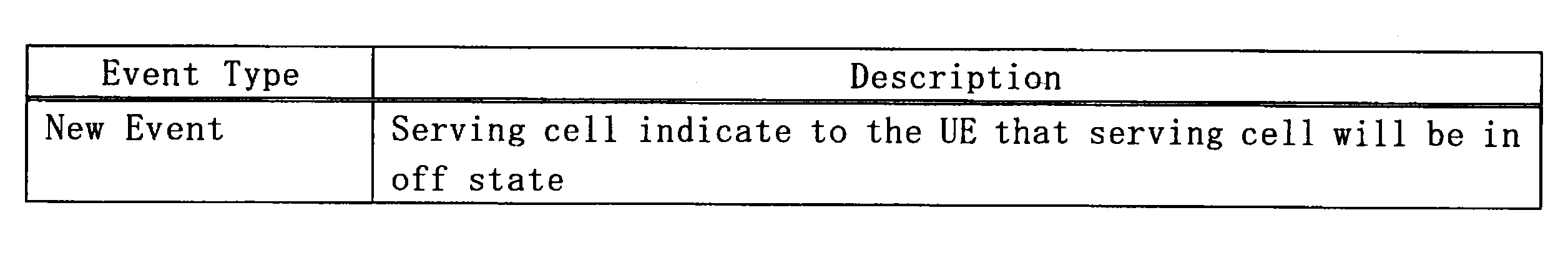
(b)測定報告
(b-1)対象のセル
例えば、上記測定報告は、上記サービングセル以外のセルについての測定報告である。即ち、端末装置100-1は、サービングセルがオフ状態になる前に、上記サービングセル以外のセルについての測定報告を行う。
(b-1)対象のセル
例えば、上記測定報告は、上記サービングセル以外のセルについての測定報告である。即ち、端末装置100-1は、サービングセルがオフ状態になる前に、上記サービングセル以外のセルについての測定報告を行う。
例えば、上記サービングセル以外の上記セルは、近隣セルを含む。さらに、上述したように、上記サービングセルが、キャリアアグリゲーションのプライマリセルである場合には、上記サービングセル以外の上記セルは、近隣セルの代わりに、又は近隣セルとともに、キャリアアグリゲーションのセカンダリセルを含んでもよい。
これにより、例えば、基地局200-1は、端末装置100-1の適切なハンドオーバ先を選択することが可能になる。
一例として、上記サービングセル以外のセルは、最も良好な測定結果を伴うセルである。これにより、例えば、オーバーヘッドを抑えつつ、最適なハンドオーバを選択することが可能になる。
(b-2)測定
上記測定報告は、端末装置100-1による測定の結果の報告である。当該測定は、RRM測定であり、例えば、受信電力又は受信品質の測定である。より具体的には、例えば、上記測定は、RSRP又はRSRQの測定である。
上記測定報告は、端末装置100-1による測定の結果の報告である。当該測定は、RRM測定であり、例えば、受信電力又は受信品質の測定である。より具体的には、例えば、上記測定は、RSRP又はRSRQの測定である。
なお、上記測定(例えば、サービングセル及び近隣セルについての測定)は、制御部143により行われてもよく、処理部140に含まれる別の構成要素により行われてもよい。
<3.3.処理の流れ>
次に、図11を参照して、第1の実施形態に係る処理の例を説明する。図11は、第1の実施形態に係る処理の概略的な流れの一例を示すシーケンス図である。
次に、図11を参照して、第1の実施形態に係る処理の例を説明する。図11は、第1の実施形態に係る処理の概略的な流れの一例を示すシーケンス図である。
基地局200-1は、サービングセル(例えば、プライマリセル)がオフ状態になる予定であることを示す情報(即ち、オフ情報)を端末装置100-1へ送信する(S401)。端末装置100-1(情報取得部141)は、当該オフ情報を取得する。
端末装置100-1(制御部143)は、上記サービングセル(例えば、プライマリセル)以外のセルについての測定を行う(S403)。
端末装置100-1(制御部143)は、上記サービングセル以外のセルについての測定報告を行う(S405)。即ち、端末装置100-1は、上記サービングセル以外のセルについての測定結果を基地局200-1に報告する。
なお、端末装置100-1は、上記オフ情報の取得(S401)後に測定を行う(S403)代わりに、上記オフ情報の取得前に行われた測定の結果を利用してもよい。
<<4.第2の実施形態>>
続いて、図12~図14を参照して、本開示の第2の実施形態を説明する。
続いて、図12~図14を参照して、本開示の第2の実施形態を説明する。
<4.1.概略>
一般的に、基地局は、端末装置により報告される測定結果に基づいて、当該端末装置のハンドオーバを決定する。また、端末装置は、周期的に、又はイベントの発生に応じて、測定結果を基地局へ報告する。
一般的に、基地局は、端末装置により報告される測定結果に基づいて、当該端末装置のハンドオーバを決定する。また、端末装置は、周期的に、又はイベントの発生に応じて、測定結果を基地局へ報告する。
セル(例えば、スモールセル)のオン/オフ状態が切り替えられる環境では、セルのオフ状態を可能な限り継続するためには、端末装置のハンドオーバ先はオフ状態のセルではなくオン状態のセルであることがより望ましい。しかし、既存のイベントでは、スモールセルのオン/オフ状態にかかわらず測定報告が行われ得る。その結果、例えば、オフ状態のセルへのハンドオーバが頻繁に行われる可能性がある。あるいは、オフ状態のセルへのハンドオーバについて厳しい条件が設定され、当該ハンドオーバが抑制されたとしても、オフ状態のセルについての測定報告が頻繁に行われ、その結果オーバーヘッドが増加し得る。
そこで、セルのオン/オフ状態が切り替えられる環境に適した測定報告を行うことを可能にする仕組みが提供されることが望ましい。
第2の実施形態では、端末装置100-2は、オン状態の近隣セルについての測定結果に関する第1のイベントの発生に応じて測定報告を行う。また、端末装置100-2は、オフ状態の近隣セルについての測定結果に関する第2のイベントの発生に応じて測定報告を行う。上記第1のイベント及び上記第2のイベントは、オフセット又は閾値が異なる。これにより、例えば、セルのオン/オフ状態が切り替えられる環境に適した測定報告を行うことが可能になる。より具体的には、例えば、オフ状態のセルについての測定報告が抑えられる。
<4.2.端末装置の構成>
次に、図12を参照して、第2の実施形態に係る端末装置100-2の構成の一例を説明する。図12は、第2の実施形態に係る端末装置100-2の構成の一例を示すブロック図である。図12を参照すると、端末装置100-2は、アンテナ部110、無線通信部120、記憶部130及び処理部150を備える。
次に、図12を参照して、第2の実施形態に係る端末装置100-2の構成の一例を説明する。図12は、第2の実施形態に係る端末装置100-2の構成の一例を示すブロック図である。図12を参照すると、端末装置100-2は、アンテナ部110、無線通信部120、記憶部130及び処理部150を備える。
アンテナ部110、無線通信部120及び記憶部130についての説明は、符号の相違を除き、第1の実施形態と第2の実施形態との間で差異はない。よって、ここでは重複する記載を省略し、処理部150のみを説明する。
(処理部150)
処理部150は、端末装置100-2の様々な機能を提供する。処理部150は、情報取得部151及び制御部153を含む。なお、処理部150は、これらの構成要素以外の他の構成要素をさらに含み得る。即ち、処理部150は、これらの構成要素の動作以外の動作も行い得る。
処理部150は、端末装置100-2の様々な機能を提供する。処理部150は、情報取得部151及び制御部153を含む。なお、処理部150は、これらの構成要素以外の他の構成要素をさらに含み得る。即ち、処理部150は、これらの構成要素の動作以外の動作も行い得る。
(情報取得部151)
情報取得部151は、近隣セルについての測定結果に関するイベントのためのオフセット又は閾値を取得する。
情報取得部151は、近隣セルについての測定結果に関するイベントのためのオフセット又は閾値を取得する。
(a)オフセット又は閾値
上記オフセット又は上記閾値は、オン状態の近隣セルについての測定結果に関する第1のイベントのためのオフセット又は閾値と、オフ状態の近隣セルについての測定結果に関する第2のイベントのためのオフセット又は閾値とを含む。上記第2のイベントのための上記オフセット又は上記閾値は、上記第1のイベントのための上記オフセット又は上記閾値とは異なる。
上記オフセット又は上記閾値は、オン状態の近隣セルについての測定結果に関する第1のイベントのためのオフセット又は閾値と、オフ状態の近隣セルについての測定結果に関する第2のイベントのためのオフセット又は閾値とを含む。上記第2のイベントのための上記オフセット又は上記閾値は、上記第1のイベントのための上記オフセット又は上記閾値とは異なる。
(b)具体的な処理
例えば、基地局200-2は、上記オフセット又は上記閾値を端末装置100-2に通知する。例えば、基地局200-2は、システム情報(例えば、SIB(System Information Block))の中で、又は個別シグナリング(例えば、RRCシグナリング)により、上記オフセット又は上記閾値を端末装置100-2に通知する。そして、上記オフセット又は上記閾値が、記憶部130に記憶される。その後のいずれかのタイミングで、情報取得部151は、上記オフセット又は上記閾値を取得する。
例えば、基地局200-2は、上記オフセット又は上記閾値を端末装置100-2に通知する。例えば、基地局200-2は、システム情報(例えば、SIB(System Information Block))の中で、又は個別シグナリング(例えば、RRCシグナリング)により、上記オフセット又は上記閾値を端末装置100-2に通知する。そして、上記オフセット又は上記閾値が、記憶部130に記憶される。その後のいずれかのタイミングで、情報取得部151は、上記オフセット又は上記閾値を取得する。
(制御部153)
制御部153は、オン状態の近隣セルについての測定結果に関する第1のイベントの発生に応じて測定報告を行う。また、制御部153は、オフ状態の近隣セルについての測定結果に関する第2のイベントの発生に応じて測定報告を行う。上記第1のイベント及び上記第2のイベントは、オフセット又は閾値が異なる。
制御部153は、オン状態の近隣セルについての測定結果に関する第1のイベントの発生に応じて測定報告を行う。また、制御部153は、オフ状態の近隣セルについての測定結果に関する第2のイベントの発生に応じて測定報告を行う。上記第1のイベント及び上記第2のイベントは、オフセット又は閾値が異なる。
例えば、上記第2のイベントは、上記第1のイベントよりも厳しい発生条件を有する。
(a)第1のイベント及び第2のイベント
(a-1)第1の例
第1の例として、上記第1のイベントは、測定結果について、オン状態の近隣セルがサービングセルよりも第1のオフセットだけ良くなることであり、上記第2のイベントは、測定結果について、オフ状態の近隣セルがサービングセルよりも第2のオフセットだけ良くなることである。上記第2のオフセットは、上記第1のオフセットよりも大きい。
(a-1)第1の例
第1の例として、上記第1のイベントは、測定結果について、オン状態の近隣セルがサービングセルよりも第1のオフセットだけ良くなることであり、上記第2のイベントは、測定結果について、オフ状態の近隣セルがサービングセルよりも第2のオフセットだけ良くなることである。上記第2のオフセットは、上記第1のオフセットよりも大きい。
例えば、上記第1のイベントは、既存のイベントA3であり、上記第2のイベントは、既存のイベントA3よりも大きいオフセットを伴う以下のような新規のイベント(又はこれに同等の新規のイベント)である。

また、例えば、上記サービングセルは、キャリアアグリゲーションのプライマリセルである。この場合に、上記第2のイベントは、以下のような新規イベントである。
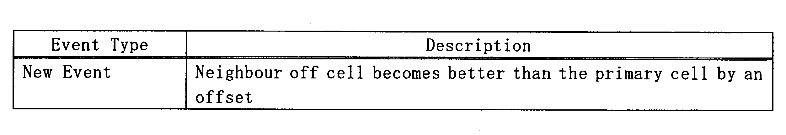
なお、上記第2のイベントは、新規のイベントではなく、既存のイベントA3であってもよい。この場合に、近隣セルの状態(オン状態又はオフ状態)に応じたオフセットが、既存のイベントA3に適用されてもよい。
このような第1の例により、例えば、オン状態の近隣セルと比べてオフ状態の近隣セルについての測定報告が抑えられる。
(a-2)第2の例
第2の例として、上記第1のイベントは、測定結果について、オン状態の近隣セルが第1の閾値よりも良くなることであり、上記第2のイベントは、測定結果について、オフ状態の近隣セルが第2の閾値よりも良くなることである。上記第2の閾値は、上記第1の閾値よりも大きい。
第2の例として、上記第1のイベントは、測定結果について、オン状態の近隣セルが第1の閾値よりも良くなることであり、上記第2のイベントは、測定結果について、オフ状態の近隣セルが第2の閾値よりも良くなることである。上記第2の閾値は、上記第1の閾値よりも大きい。
例えば、上記第1のイベントは、既存のイベントA4であり、上記第2のイベントは、既存のイベントA4よりも大きい閾値を伴う以下のような新規のイベント(又はこれに同等の新規のイベント)である。
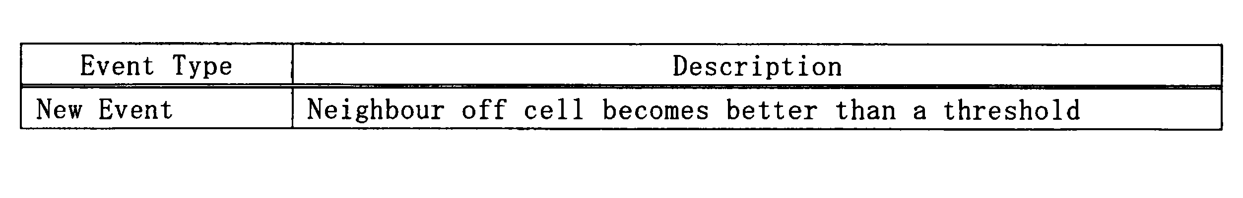
なお、上記第2のイベントは、新規のイベントではなく、既存のイベントA4であってもよい。この場合に、近隣セルの状態(オン状態又はオフ状態)に応じた閾値が、既存のイベントA4に適用されてもよい。
このような第2の例により、例えば、オン状態の近隣セルと比べてオフ状態の近隣セルについての測定報告が抑えられる。
(a-3)第3の例
第3の例として、上記第1のイベントは、測定結果について、サービングセルが第1の閾値よりも悪くなり、オン状態の近隣セルが第2の閾値よりも良くなることであり、上記第2のイベントは、測定結果について、サービングセルが第3の閾値よりも悪くなり、オフ状態の近隣セルが第4の閾値よりも良くなることである。上記第4の閾値は上記第2の閾値よりも大きく、又は上記第3の閾値は上記第1の閾値よりも小さい。
第3の例として、上記第1のイベントは、測定結果について、サービングセルが第1の閾値よりも悪くなり、オン状態の近隣セルが第2の閾値よりも良くなることであり、上記第2のイベントは、測定結果について、サービングセルが第3の閾値よりも悪くなり、オフ状態の近隣セルが第4の閾値よりも良くなることである。上記第4の閾値は上記第2の閾値よりも大きく、又は上記第3の閾値は上記第1の閾値よりも小さい。
例えば、上記第1のイベントは、既存のイベントA5であり、上記第2のイベントは、既存のイベントA5とは異なる閾値を伴う以下のような新規のイベント(又はこれに同等の新規のイベント)である。
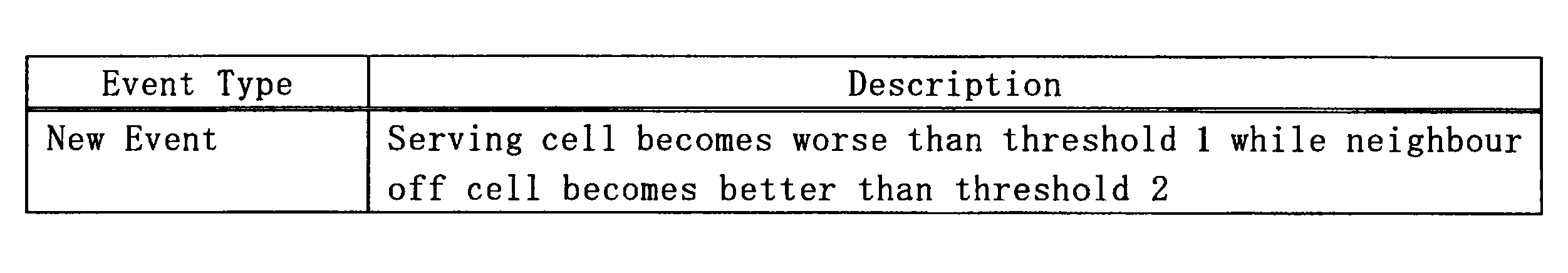
上記新規イベントは、既存のイベントA5よりも、オフ状態の近隣セルについての閾値(threshold 2)が大きく、且つ/又は、サービングセルについての閾値(threshold 1)が小さい。
また、例えば、上記サービングセルは、キャリアアグリゲーションのプライマリセルである。この場合に、上記第2のイベントは、以下のような新規イベントである。

なお、上記第2のイベントは、新規のイベントではなく、既存のイベントA5であってもよい。この場合に、近隣セルの状態(オン状態又はオフ状態)に応じた閾値が、既存のイベントA5に適用されてもよい。
このような第3の例により、例えば、オン状態の近隣セルと比べてオフ状態の近隣セルについての測定報告が抑えられる。
(a-4)第4の例
第4の例として、上記第1のイベントは、測定結果について、オン状態の近隣セルがセカンダリセルよりも第1のオフセットだけ良くなることであり、上記第2のイベントは、測定結果について、オフ状態の近隣セルがセカンダリセルよりも第2のオフセットだけ良くなることである。上記第2のオフセットは、上記第1のオフセットよりも大きい。
第4の例として、上記第1のイベントは、測定結果について、オン状態の近隣セルがセカンダリセルよりも第1のオフセットだけ良くなることであり、上記第2のイベントは、測定結果について、オフ状態の近隣セルがセカンダリセルよりも第2のオフセットだけ良くなることである。上記第2のオフセットは、上記第1のオフセットよりも大きい。
例えば、上記第1のイベントは、既存のイベントA6であり、上記第2のイベントは、既存のイベントA6よりも大きいオフセットを伴う以下のような新規のイベント(又はこれに同等の新規のイベント)である。

なお、上記第2のイベントは、新規のイベントではなく、既存のイベントA6であってもよい。この場合に、近隣セルの状態(オン状態又はオフ状態)に応じたオフセットが、既存のイベントA6に適用されてもよい。
このような第1の例により、例えば、オン状態の近隣セルと比べてオフ状態の近隣セルについての測定報告が抑えられる。
(b)測定
上記測定報告は、端末装置100-2による測定の結果の報告である。当該測定は、RRM測定であり、例えば、受信電力又は受信品質の測定である。より具体的には、例えば、上記測定は、RSRP又はRSRQの測定である。
上記測定報告は、端末装置100-2による測定の結果の報告である。当該測定は、RRM測定であり、例えば、受信電力又は受信品質の測定である。より具体的には、例えば、上記測定は、RSRP又はRSRQの測定である。
上記測定は、リファレンス信号に基づいて行われる。当該リファレンス信号は、例えば、オン状態のセルにおいて送信されるCRS、及び/又は、オフ状態のセル(及びオン状態のセル)において送信されるDRSである。
なお、上記測定(例えば、サービングセル及び近隣セルについての測定)は、制御部153により行われてもよく、処理部150に含まれる別の構成要素により行われてもよい
<4.3.基地局の構成>
次に、図13を参照して、第2の実施形態に係る基地局200-2の構成の一例を説明する。図13は、第2の実施形態に係る基地局200-2の構成の一例を示すブロック図である。図13を参照すると、基地局200-2は、アンテナ部210、無線通信部220、ネットワーク通信部230、記憶部240及び処理部250を備える。
次に、図13を参照して、第2の実施形態に係る基地局200-2の構成の一例を説明する。図13は、第2の実施形態に係る基地局200-2の構成の一例を示すブロック図である。図13を参照すると、基地局200-2は、アンテナ部210、無線通信部220、ネットワーク通信部230、記憶部240及び処理部250を備える。
(アンテナ部210)
アンテナ部210は、無線通信部220により出力される信号を電波として空間に放射する。また、アンテナ部210は、空間の電波を信号に変換し、当該信号を無線通信部220へ出力する。
アンテナ部210は、無線通信部220により出力される信号を電波として空間に放射する。また、アンテナ部210は、空間の電波を信号に変換し、当該信号を無線通信部220へ出力する。
(無線通信部220)
無線通信部220は、信号を送受信する。例えば、無線通信部220は、端末装置へのダウンリンク信号を送信し、端末装置からのアップリンク信号を受信する。
無線通信部220は、信号を送受信する。例えば、無線通信部220は、端末装置へのダウンリンク信号を送信し、端末装置からのアップリンク信号を受信する。
(ネットワーク通信部230)
ネットワーク通信部230は、情報を送受信する。例えば、ネットワーク通信部230は、他のノードへの情報を送信し、他のノードからの情報を受信する。例えば、上記他のノードは、コアネットワーク及び他の基地局を含む。一例として、上記他のノードは、制御エンティティ300-2を含む。
ネットワーク通信部230は、情報を送受信する。例えば、ネットワーク通信部230は、他のノードへの情報を送信し、他のノードからの情報を受信する。例えば、上記他のノードは、コアネットワーク及び他の基地局を含む。一例として、上記他のノードは、制御エンティティ300-2を含む。
(記憶部240)
記憶部240は、基地局200-2の動作のためのプログラム及びデータを一時的にまたは恒久的に記憶する。
記憶部240は、基地局200-2の動作のためのプログラム及びデータを一時的にまたは恒久的に記憶する。
(処理部250)
処理部250は、基地局200-2の様々な機能を提供する。処理部250は、情報取得部251及び制御部253を含む。なお、処理部250は、これらの構成要素以外の他の構成要素をさらに含み得る。即ち、処理部250は、これらの構成要素の動作以外の動作も行い得る。
処理部250は、基地局200-2の様々な機能を提供する。処理部250は、情報取得部251及び制御部253を含む。なお、処理部250は、これらの構成要素以外の他の構成要素をさらに含み得る。即ち、処理部250は、これらの構成要素の動作以外の動作も行い得る。
(情報取得部251)
情報取得部251は、近隣セルについての測定結果に関するイベントのためのオフセット又は閾値を取得する。
情報取得部251は、近隣セルについての測定結果に関するイベントのためのオフセット又は閾値を取得する。
(a)オフセット又は閾値
上記オフセット又は上記閾値は、オン状態の近隣セルについての測定結果に関する第1のイベントのためのオフセット又は閾値と、オフ状態の近隣セルについての測定結果に関する第2のイベントのためのオフセット又は閾値とを含む。上記第2のイベントのための上記オフセット又は上記閾値は、上記第1のイベントのための上記オフセット又は上記閾値とは異なる。
上記オフセット又は上記閾値は、オン状態の近隣セルについての測定結果に関する第1のイベントのためのオフセット又は閾値と、オフ状態の近隣セルについての測定結果に関する第2のイベントのためのオフセット又は閾値とを含む。上記第2のイベントのための上記オフセット又は上記閾値は、上記第1のイベントのための上記オフセット又は上記閾値とは異なる。
(b)具体的な処理
例えば、上記オフセット又は上記閾値が、記憶部240に記憶され、情報取得部251は、記憶部240から上記オフセット又は上記閾値を取得する。
例えば、上記オフセット又は上記閾値が、記憶部240に記憶され、情報取得部251は、記憶部240から上記オフセット又は上記閾値を取得する。
(制御部253)
制御部253は、上記イベントのための上記オフセット又は上記閾値を端末装置100-2に通知する。
制御部253は、上記イベントのための上記オフセット又は上記閾値を端末装置100-2に通知する。
例えば、制御部253は、システム情報(例えば、SIB)の中で、又は個別シグナリング(例えば、RRCシグナリング)により、上記オフセット又は上記閾値を端末装置100-2に通知する。
<4.4.処理の流れ>
次に、図14を参照して、第2の実施形態に係る処理の例を説明する。図14は、第2の実施形態に係る処理の概略的な流れの一例を示すシーケンス図である。
次に、図14を参照して、第2の実施形態に係る処理の例を説明する。図14は、第2の実施形態に係る処理の概略的な流れの一例を示すシーケンス図である。
基地局200-2(制御部253)は、近隣セルについての測定結果に関するイベントのためのオフセット及び/又は閾値を端末装置100-2に通知する(S421)。端末装置100-2(情報取得部151)は、当該オフセット及び/又は当該閾値を取得する。
端末装置100-2(処理部250)は、セルについての測定を行う(S423)。当該セルは、サービングセル及び隣接セルを含む。
端末装置100-2(制御部153)は、イベントの発生に応じて測定報告を行う(S425)。即ち、端末装置100-2は、セルについての測定結果を基地局200-2へ報告する。例えば、端末装置100-2(制御部153)は、オン状態の近隣セルの測定結果に関する第1のイベントの発生に応じて測定報告を行う。また、端末装置100-2(制御部153)は、オフ状態の近隣セルの測定結果に関する第2のイベントの発生に応じて測定報告を行う。上記第1のイベント及び上記第2のイベントは、オフセット又は閾値が異なる。
<<5.第3の実施形態>>
続いて、図15及び図16を参照して、本開示の第3の実施形態を説明する。
続いて、図15及び図16を参照して、本開示の第3の実施形態を説明する。
<5.1.概略>
一般的に、基地局は、端末装置により報告される測定結果に基づいて、当該端末装置のハンドオーバを決定する。また、端末装置は、周期的に、又はイベントの発生に応じて、測定結果を基地局へ報告する。
一般的に、基地局は、端末装置により報告される測定結果に基づいて、当該端末装置のハンドオーバを決定する。また、端末装置は、周期的に、又はイベントの発生に応じて、測定結果を基地局へ報告する。
セル(例えば、スモールセル)のオン/オフ状態が切り替えられる環境において、キャリアアグリゲーションが行われる場合に、各コンポーネントキャリア(CC)がアクティベート/ディアクティベートされる。例えば、端末装置のトラフィックが増えると、ディアクティベートされているCCがアクティベートされることが望まれる(即ち、オフ状態のセルがオン状態にされることが望まれる)。しかし、既存のイベントでは、端末装置のトラフィックが増えた際に、測定結果が基地局に報告されない可能性がある。
そこで、セルのオン/オフ状態が切り替えられる環境に適した測定報告を行うことを可能にする仕組みが提供されることが望ましい。
第3の実施形態では、端末装置100-3は、端末装置100-3のトラフィックに関する所定の条件が満たされる場合に測定報告を行う。これにより、例えば、セルのオン/オフ状態が切り替えられる環境に適した測定報告を行うことが可能になる。より具体的には、例えば、トラフィックの増加に応じて追加されるキャリア(セル)の選択に有用な測定報告が行われる。
<5.2.端末装置の構成>
次に、図15を参照して、第3の実施形態に係る端末装置100-3の構成の一例を説明する。図15は、第3の実施形態に係る端末装置100-3の構成の一例を示すブロック図である。図15を参照すると、端末装置100-3は、アンテナ部110、無線通信部120、記憶部130及び処理部160を備える。
次に、図15を参照して、第3の実施形態に係る端末装置100-3の構成の一例を説明する。図15は、第3の実施形態に係る端末装置100-3の構成の一例を示すブロック図である。図15を参照すると、端末装置100-3は、アンテナ部110、無線通信部120、記憶部130及び処理部160を備える。
アンテナ部110、無線通信部120及び記憶部130についての説明は、符号の相違を除き、第1の実施形態と第3の実施形態との間で差異はない。よって、ここでは重複する記載を省略し、処理部160のみを説明する。
(処理部160)
処理部160は、端末装置100-3の様々な機能を提供する。処理部160は、情報取得部161及び制御部163を含む。なお、処理部160は、これらの構成要素以外の他の構成要素をさらに含み得る。即ち、処理部160は、これらの構成要素の動作以外の動作も行い得る。
処理部160は、端末装置100-3の様々な機能を提供する。処理部160は、情報取得部161及び制御部163を含む。なお、処理部160は、これらの構成要素以外の他の構成要素をさらに含み得る。即ち、処理部160は、これらの構成要素の動作以外の動作も行い得る。
(情報取得部161)
情報取得部161は、端末装置100-3のトラフィックに関する情報(以下、「トラフィック情報」と呼ぶ)を取得する。
情報取得部161は、端末装置100-3のトラフィックに関する情報(以下、「トラフィック情報」と呼ぶ)を取得する。
第1の例として、上記トラフィック情報は、端末装置100-3のトラフィックロードである。第2の例として、上記トラフィック情報は、端末装置100-3のトラフィック量であってもよい。
例えば、処理部160は、上記トラフィック情報を算出し、情報取得部161は、当該トラフィック情報を取得する。
(制御部163)
制御部163は、上記トラフィック情報に関する所定の条件が満たされる場合に測定報告を行う。
制御部163は、上記トラフィック情報に関する所定の条件が満たされる場合に測定報告を行う。
(a)所定の条件
(a-1)第1の例
上述したように、第1の例として、上記トラフィック情報は、端末装置100-3のトラフィックロードである。この場合に、上記所定の条件は、端末装置100-3のトラフィックロードが閾値以上になることである。即ち、制御部163は、端末装置100-3のトラフィックロードが閾値以上になる場合に測定報告を行う。
(a-1)第1の例
上述したように、第1の例として、上記トラフィック情報は、端末装置100-3のトラフィックロードである。この場合に、上記所定の条件は、端末装置100-3のトラフィックロードが閾値以上になることである。即ち、制御部163は、端末装置100-3のトラフィックロードが閾値以上になる場合に測定報告を行う。
(a-2)第2の例
上述したように、第2の例として、上記トラフィック情報は、端末装置100-3のトラフィック量であってもよい。この場合に、上記所定の条件は、端末装置100-3のトラフィック量が閾値以上になることであってもよい。即ち、制御部163は、端末装置100-3のトラフィック量が閾値以上になる場合に測定報告を行ってもよい。なお、該上記閾値は、端末装置100-3の平均スループットであってもよい。
上述したように、第2の例として、上記トラフィック情報は、端末装置100-3のトラフィック量であってもよい。この場合に、上記所定の条件は、端末装置100-3のトラフィック量が閾値以上になることであってもよい。即ち、制御部163は、端末装置100-3のトラフィック量が閾値以上になる場合に測定報告を行ってもよい。なお、該上記閾値は、端末装置100-3の平均スループットであってもよい。
(b)測定報告
(b-1)対象のセル
例えば、上記測定報告は、オフ状態のセルについての測定報告を含む。より具体的には、例えば、上記測定報告は、オフ状態のスモールセルについての測定報告を含む。即ち、制御部163は、上記所定の条件が満たされる場合に、オフ状態のスモールセルについての測定報告を行う。
(b-1)対象のセル
例えば、上記測定報告は、オフ状態のセルについての測定報告を含む。より具体的には、例えば、上記測定報告は、オフ状態のスモールセルについての測定報告を含む。即ち、制御部163は、上記所定の条件が満たされる場合に、オフ状態のスモールセルについての測定報告を行う。
これにより、例えば、トラフィックの増加に応じてオフ状態のセルをオン状態に切り替えられ得る。
なお、上記測定報告は、オン状態のセルについての測定報告を含んでもよい。
(b-2)測定
上記測定報告は、端末装置100-3による測定の結果の報告である。当該測定は、RRM測定であり、例えば、受信電力又は受信品質の測定である。より具体的には、例えば、上記測定は、RSRP又はRSRQの測定である。
上記測定報告は、端末装置100-3による測定の結果の報告である。当該測定は、RRM測定であり、例えば、受信電力又は受信品質の測定である。より具体的には、例えば、上記測定は、RSRP又はRSRQの測定である。
上記測定は、リファレンス信号に基づいて行われる。当該リファレンス信号は、例えば、オン状態のセルにおいて送信されるCRS、及び/又は、オフ状態のセル(及びオン状態のセル)において送信されるDRSである。
なお、上記測定(例えば、サービングセル及び近隣セルについての測定)は、制御部163により行われてもよく、処理部160に含まれる別の構成要素により行われてもよい。
<5.3.処理の流れ>
次に、図16を参照して、第3の実施形態に係る処理の例を説明する。図16は、第3の実施形態に係る処理の概略的な流れの一例を示すフローチャートである。
次に、図16を参照して、第3の実施形態に係る処理の例を説明する。図16は、第3の実施形態に係る処理の概略的な流れの一例を示すフローチャートである。
情報取得部161は、端末装置100-3のトラフィックに関する情報(即ち、トラフィック情報)を取得する(S441)。
そして、情報取得部161は、上記トラフィック情報に関する所定の条件が満たされるかを判定する(S443)。上記所定の条件が満たされない場合には(S443:NO)、処理は終了する。
上記所定の条件が満たされる場合には(S443:YES)、制御部163は測定報告を行う(S445)。当該測定報告は、例えば、オフ状態のセルについての測定報告を含む。そして、処理は終了する。
<<6.第4の実施形態>>
続いて、図17及び図18を参照して、本開示の第4の実施形態を説明する。
続いて、図17及び図18を参照して、本開示の第4の実施形態を説明する。
<6.1.概略>
近隣セルへの干渉を抑えるために、セル(例えば、スモールセル)のオン/オフ状態を適応的に切り替えることが検討されている。
近隣セルへの干渉を抑えるために、セル(例えば、スモールセル)のオン/オフ状態を適応的に切り替えることが検討されている。
しかし、例えば、端末装置による測定の結果(のみ)に基づいてセルのオン/オフ状態が切り替えられると、端末装置にとっての必要性が低いにもかかわらず、セルがオン状態からオフ状態に切り替えられる可能性がある。一例として、端末装置が非常に少量のパケットを送信しようとしている場合に、信号強度が小さいオン状態のセルにおいて端末装置が即座に通信するのではなく、信号強度が大きいオフ状態のセルがオン状態に切替えられ、その後端末装置が当該セルにおいて通信する可能性がある。
そこで、セルのオン/オフ状態をより適切に切り替えることを可能にする仕組みが提供されることが望ましい。
第4の実施形態では、制御エンティティ300-4は、端末装置100-4により報告される、オフ状態のセルについての測定結果と、端末装置100-4のバッファステータスに関する情報とに基づいて、上記セルのオン状態への切替えを決定する。これにより、例えば、セルのオン/オフ状態をより適切に切り替えることが可能になる。より具体的には、例えば、必要性が高い場合に、オフ状態のセルがオン状態に切り替えられる。
<6.2.制御エンティティの構成>
次に、図17を参照して、第4の実施形態に係る制御エンティティ300-4の構成の一例を説明する。図17は、第4の実施形態に係る制御エンティティ300-4の構成の一例を示すブロック図である。図17を参照すると、制御エンティティ300-4は、通信部310、記憶部320及び処理部330を備える。
次に、図17を参照して、第4の実施形態に係る制御エンティティ300-4の構成の一例を説明する。図17は、第4の実施形態に係る制御エンティティ300-4の構成の一例を示すブロック図である。図17を参照すると、制御エンティティ300-4は、通信部310、記憶部320及び処理部330を備える。
(通信部310)
通信部310は、情報を送受信する。例えば、通信部310は、他のノードへの情報を送信し、他のノードからの情報を受信する。例えば、上記他のノードは、コアネットワーク及び基地局を含む。一例として、上記他のノードは、基地局200-4を含む。
通信部310は、情報を送受信する。例えば、通信部310は、他のノードへの情報を送信し、他のノードからの情報を受信する。例えば、上記他のノードは、コアネットワーク及び基地局を含む。一例として、上記他のノードは、基地局200-4を含む。
(記憶部320)
記憶部320は、制御エンティティ300-4の動作のためのプログラム及びデータを一時的にまたは恒久的に記憶する。
記憶部320は、制御エンティティ300-4の動作のためのプログラム及びデータを一時的にまたは恒久的に記憶する。
(処理部330)
処理部330は、制御エンティティ300-4の様々な機能を提供する。処理部330は、情報取得部331及び制御部333を含む。なお、処理部330は、これらの構成要素以外の他の構成要素をさらに含み得る。即ち、処理部330は、これらの構成要素の動作以外の動作も行い得る。
処理部330は、制御エンティティ300-4の様々な機能を提供する。処理部330は、情報取得部331及び制御部333を含む。なお、処理部330は、これらの構成要素以外の他の構成要素をさらに含み得る。即ち、処理部330は、これらの構成要素の動作以外の動作も行い得る。
(情報取得部331)
情報取得部331は、端末装置100-4により報告される、オフ状態のセルについての測定結果と、端末装置100-4のバッファステータスに関する情報とを取得する。上記セルは、例えば、オフ状態のスモールセルである。
情報取得部331は、端末装置100-4により報告される、オフ状態のセルについての測定結果と、端末装置100-4のバッファステータスに関する情報とを取得する。上記セルは、例えば、オフ状態のスモールセルである。
例えば、上記情報は、端末装置100-4からのバッファステータスレポート(Buffer Status Report:BSR)である。
具体的には、例えば、端末装置100-4は、オフ状態のセルについての測定結果を、端末装置100-4のBSRとともに基地局200に報告する。そして、基地局200-4は、上記測定結果及び上記BRSを制御エンティティ300-4に提供する。そして、情報取得部331は、上記測定結果及び上記BRSを取得する。
なお、端末装置100-4は、上記測定結果とともにBSRを報告せず、基地局200が、既に取得しているBSRを、上記測定結果とともに制御エンティティ300-4に提供してもよい。また、上記情報は、BSRではなく、端末装置100-4のバッファステータスを示す別の情報であってもよい。
(制御部333)
制御部333は、上記測定結果及び上記情報(例えば、BSR)に基づいて、上記セルのオン状態への切替えを決定する。
制御部333は、上記測定結果及び上記情報(例えば、BSR)に基づいて、上記セルのオン状態への切替えを決定する。
例えば、制御部333は、上記測定結果が良好であり、且つ、端末装置100-4のバッファに多くのデータが蓄積されている場合に、上記セルのオン状態への切替えを決定する。より具体的には、例えば、制御部333は、上記測定結果が第1の閾値以上であり、且つ、端末装置100-4のバッファにおける蓄積データ量が第2の閾値以上である場合に、上記セルのオン状態への切替えを決定する。
また、例えば、制御部333は、上記切替えを決定すると、当該切替えを、上記セルの基地局に指示する。
なお、当然ながら、制御部333は、1つの端末装置100-4からの上記測定結果及び上記情報(例えば、BSR)のみではなく、複数の端末装置100-4からの上記測定結果及び上記情報(例えば、BSR)に基づいて、上記セルのオン状態への切替えを決定してもよい。
<6.3.処理の流れ>
次に、図18を参照して、第4の実施形態に係る処理の例を説明する。図18は、第4の実施形態に係る処理の概略的な流れの一例を示すシーケンス図である。
次に、図18を参照して、第4の実施形態に係る処理の例を説明する。図18は、第4の実施形態に係る処理の概略的な流れの一例を示すシーケンス図である。
端末装置100-4は、オフ状態のセルについての測定結果及びBSRを基地局200-4に報告する(S461)。
基地局200-4は、上記測定結果及び上記BSRを制御エンティティ300-4に提供する(S463)。制御エンティティ300-4(情報取得部331)は、上記測定結果及び上記BSRを取得する。
制御エンティティ300-4(制御部333)は、上記測定結果及び上記BSRに基づいて、オフ状態の上記セルのオン状態への切替えを決定する(S465)。
そして、制御エンティティ300-4(制御部333)は、上記切替えを、上記セルの基地局に指示する(S467)。
<<7.第5の実施形態>>
続いて、図19及び図20を参照して、本開示の第5の実施形態を説明する。
続いて、図19及び図20を参照して、本開示の第5の実施形態を説明する。
<7.1.概略>
一般的に、端末装置は、ネットワーク(基地局)から提供される近隣セルリスト(Neighbour Cell List:NCL)に基づいて測定を行う。
一般的に、端末装置は、ネットワーク(基地局)から提供される近隣セルリスト(Neighbour Cell List:NCL)に基づいて測定を行う。
セル(例えば、スモールセル)のオン/オフ状態が切り替えられる環境では、オフ状態のセルの基地局は、DRSを送信し、端末装置は、DRSに基づいて、オフ状態の上記セルについての測定を行う。そして、測定結果に応じて測定報告が行われ、オフ状態の上記セルがオン状態に切替えられ得る。しかし、例えば、既存のNCLでは、セルのオン/オフ状態は考慮されていないので、端末装置は、望ましくない測定及び測定報告を行い得る。一例として、端末装置が、セルについての測定及び測定報告を行い、当該セルへの当該端末装置のハンドオーバが行われた後に、当該セルが、オン状態からオフ状態に切り替えられ得る。その結果、さらなるハンドオーバが必要になり、システムパフォーマンスが低下し得る。
そこで、セルのオン/オフ状態が切り替えられる環境に適した測定報告を行うことを可能にする仕組みが提供されることが望ましい。
第5の実施形態では、基地局200-5は、セルのオン/オフ状態の予定に関する情報に基づいて、端末装置100-5により測定が行われるセルの候補、又は当該セルの候補の優先度を決定する。これにより、例えば、セルのオン/オフ状態が切り替えられる環境に適した測定報告を行うことが可能になる。より具体的には、例えば、オフ状態になりそうなセルについての測定報告よりも、オフ状態になりそうにないセルについての測定報告が行われる。その結果、オフ状態になりそうにないセルへのハンドオーバが行われ得る。
<7.2.基地局の構成>
次に、図19を参照して、第5の実施形態に係る基地局200-5の構成の一例を説明する。図19は、第5の実施形態に係る基地局200-5の構成の一例を示すブロック図である。図19を参照すると、基地局200-5は、アンテナ部210、無線通信部220、ネットワーク通信部230、記憶部240及び処理部260を備える。
次に、図19を参照して、第5の実施形態に係る基地局200-5の構成の一例を説明する。図19は、第5の実施形態に係る基地局200-5の構成の一例を示すブロック図である。図19を参照すると、基地局200-5は、アンテナ部210、無線通信部220、ネットワーク通信部230、記憶部240及び処理部260を備える。
アンテナ部210、無線通信部220、ネットワーク通信部230及び記憶部240についての説明は、符号の相違を除き、第2の実施形態と第5の実施形態との間で差異はない。よって、ここでは重複する記載を省略し、処理部260のみを説明する。
(処理部260)
処理部260は、基地局200-5の様々な機能を提供する。処理部260は、情報取得部261及び制御部263を含む。なお、処理部260は、これらの構成要素以外の他の構成要素をさらに含み得る。即ち、処理部260は、これらの構成要素の動作以外の動作も行い得る。
処理部260は、基地局200-5の様々な機能を提供する。処理部260は、情報取得部261及び制御部263を含む。なお、処理部260は、これらの構成要素以外の他の構成要素をさらに含み得る。即ち、処理部260は、これらの構成要素の動作以外の動作も行い得る。
(情報取得部261)
情報取得部261は、セルのオン/オフ状態の予定に関する情報(以下、「オン/オフ予定関連情報」と呼ぶ)を取得する。当該セルは、例えば、スモールセルである。
情報取得部261は、セルのオン/オフ状態の予定に関する情報(以下、「オン/オフ予定関連情報」と呼ぶ)を取得する。当該セルは、例えば、スモールセルである。
(a)オン/オフ予定関連情報
(a-1)オフ予定情報
第1の例として、上記オン/オフ予定関連情報は、オン状態からオフ状態への切替えの予定を示す情報(以下、「オフ予定情報」と呼ぶ)である。例えば、上記オフ予定情報は、オン状態からオフ状態への切替えの予定を有するセルを示す。具体的には、上記オフ予定情報は、オン状態からオフ状態への切替えの予定を有するセルのみを示す情報であってもよく、あるいは、セルごとに上記予定の有無を示す情報であってもよい。
(a-1)オフ予定情報
第1の例として、上記オン/オフ予定関連情報は、オン状態からオフ状態への切替えの予定を示す情報(以下、「オフ予定情報」と呼ぶ)である。例えば、上記オフ予定情報は、オン状態からオフ状態への切替えの予定を有するセルを示す。具体的には、上記オフ予定情報は、オン状態からオフ状態への切替えの予定を有するセルのみを示す情報であってもよく、あるいは、セルごとに上記予定の有無を示す情報であってもよい。
(a-2)オン状態継続時間情報
第2の例として、上記オン/オフ予定関連情報は、セルのオン状態が継続する時間(以下、「オン状態継続時間」と呼ぶ)を示す情報(以下、「オン状態継続時間情報」と呼ぶ)であってもよい。例えば、上記オン状態継続時間情報は、セルごとに、セルのオン状態が継続する時間(即ち、オン状態継続時間)を示す。
第2の例として、上記オン/オフ予定関連情報は、セルのオン状態が継続する時間(以下、「オン状態継続時間」と呼ぶ)を示す情報(以下、「オン状態継続時間情報」と呼ぶ)であってもよい。例えば、上記オン状態継続時間情報は、セルごとに、セルのオン状態が継続する時間(即ち、オン状態継続時間)を示す。
例えば、セルは、少なくともオン状態継続時間まではオン状態を継続する。なお、セルは、オン状態継続時間が到来した後に、オン状態をさらに継続してもよく、オン状態継続時間が到来すると、オフ状態に切替えられてもよい。
なお、上記オン状態継続時間は、絶対的な時間(例えば、SFN(System Frame Number)など)であってもよく、又は、いずれかの時間を基準とする相対的な時間であってもよい。
なお、上記オン状態継続時間は、スモールセル内のバッファステータス、収容ユーザ数、トラフィック量、及びオン/オフ統計データなどの、スモールセルのパラメータに基づいて、算出され得る。
(b)具体的な処理
例えば、他のノード(例えば、制御エンティティ300-5)が、上記オン/オフ予定関連情報を生成し、当該オン/オフ予定関連情報を基地局200-5に提供する。そして、当該オン/オフ予定関連情報が、記憶部240に記憶される。その後のいずれかのタイミングで、情報取得部261は、記憶部240から、上記オン/オフ予定関連情報を取得する。
例えば、他のノード(例えば、制御エンティティ300-5)が、上記オン/オフ予定関連情報を生成し、当該オン/オフ予定関連情報を基地局200-5に提供する。そして、当該オン/オフ予定関連情報が、記憶部240に記憶される。その後のいずれかのタイミングで、情報取得部261は、記憶部240から、上記オン/オフ予定関連情報を取得する。
(制御部263)
(a)セル候補/優先度の決定
制御部263は、上記オン/オフ予定関連情報に基づいて、端末装置100-5により測定が行われるセルの候補、又は当該セルの候補の優先度を決定する。
(a)セル候補/優先度の決定
制御部263は、上記オン/オフ予定関連情報に基づいて、端末装置100-5により測定が行われるセルの候補、又は当該セルの候補の優先度を決定する。
(a-1)オフ予定情報
上述したように、第1の例として、上記オン/オフ予定関連情報は、上記オフ予定情報(即ち、オン状態からオフ状態への切替えの予定を示す情報)である。
上述したように、第1の例として、上記オン/オフ予定関連情報は、上記オフ予定情報(即ち、オン状態からオフ状態への切替えの予定を示す情報)である。
この場合に、例えば、制御部263は、オン状態からオフ状態への切替えの予定を有するセルを上記セルの候補には含めない。より具体的には、例えば、制御部263は、オン状態からオフ状態への切替えの予定を有するセルがNCLに含まれないように、NCLを決定する。これにより、例えば、オフ状態の予定を有しないセルについての測定報告のみが行われる。
あるいは、制御部263は、オン状態からオフ状態への切替えの予定を有するセルの優先度をより低くしてもよい。より具体的には、制御部263は、オン状態からオフ状態への切替えの予定を有するセルの優先度が低く(例えば、最低の優先度)になるように、NCLを決定してもよい。これにより、例えば、オフ状態の予定を有しないセルについての測定報告が優先的に行われる。
(a-2)オン状態継続時間情報
上述したように、第2の例として、上記オン/オフ予定関連情報は、上記オン状態継続時間情報(即ち、セルのオン状態が継続する時間(オン状態継続時間)を示す情報)であってもよい。
上述したように、第2の例として、上記オン/オフ予定関連情報は、上記オン状態継続時間情報(即ち、セルのオン状態が継続する時間(オン状態継続時間)を示す情報)であってもよい。
この場合に、制御部263は、オン状態継続時間が所定の期間内に到来するセルを上記セルの候補には含めないようにしてもよい。より具体的には、制御部263は、オン状態継続時間が所定の期間内に到来するセルがNCLに含まれないように、NCLを決定してもよい。これにより、例えば、十分な期間にわたってオン状態を継続するセルについての測定報告のみが行われる。
あるいは、制御部263は、オン状態継続時間が所定の期間内に到来するセルの優先度を低くしてもよい。より具体的には、制御部263は、オン状態継続時間が所定の期間内に到来するセルの優先度が低く(例えば、最低の優先度)になるように、NCLを決定してもよい。これにより、例えば、十分な時間にわたってオン状態を継続するセルについての測定報告が優先的に行われる。
なお、上記オン状態継続時間情報が、端末装置100-5ごとに生成される場合には、上記「所定の期間」は、「端末装置100-5によるデータの送信ための期間」に置き換えられてもよい。即ち、制御部263は、端末装置100-5によるデータの送信のための期間内にオン状態継続時間が到来するセルを上記セルの候補には含めないようにしてもよく、又は、端末装置100-5によるデータの送信のための期間内にオン状態継続時間が到来するセルの優先度をより低くしてもよい。
また、NCLにおけるセルの候補、及び/又は、NCLにおける優先度は、オン/オフ予定関連情報のみではなく、BSR(Buffer Status Report)、QoS(Quality of Service)、及び/又は通信状況の統計データなどの他の情報にさらに基づいて、決定され得る。
(a-3)測定
上記測定は、RRM測定であり、例えば、受信電力又は受信品質の測定である。より具体的には、例えば、上記測定は、RSRP又はRSRQの測定である。
上記測定は、RRM測定であり、例えば、受信電力又は受信品質の測定である。より具体的には、例えば、上記測定は、RSRP又はRSRQの測定である。
一例として、上記測定は、Inter-Frequency measurementである。即ち、上記測定は、端末装置100-5により使用されていない周波数帯域(例えば、コンポーネントキャリア)についての測定である。
(b)通知
例えば、制御部263は、決定される上記セルの候補又は上記優先度を端末装置100-5に通知する。
例えば、制御部263は、決定される上記セルの候補又は上記優先度を端末装置100-5に通知する。
より具体的には、例えば、制御部263は、決定される上記セルの候補又は上記優先度を示すNCLを、端末装置100-5に通知する。例えば、制御部263は、システム情報(例えば、SIB)の中で、NCLを端末装置100-5に通知する。なお、制御部263は、個別のシグナリング(例えば、RRCシグナリング)により、NCLを端末装置100-5に通知してもよい。
<7.3.処理の流れ>
次に、図20を参照して、第5の実施形態に係る処理の例を説明する。図20は、第5の実施形態に係る処理の概略的な流れの一例を示すシーケンス図である。
次に、図20を参照して、第5の実施形態に係る処理の例を説明する。図20は、第5の実施形態に係る処理の概略的な流れの一例を示すシーケンス図である。
基地局200-5(情報取得部261)は、セルのオン/オフ状態の予定に関する情報(即ち、オン/オフ予定関連情報)を取得する(S481)。
そして、基地局200-5(制御部263)は、上記オン/オフ予定関連情報に基づいて、端末装置100-5により測定が行われるセルの候補、又は当該セルの候補の優先度を決定する(S483)。具体的には、例えば、基地局200-5は、上記オン/オフ予定関連情報に基づいてNCLを決定する。
その後、基地局200-5(制御部263)は、上記NCLを端末装置100-5に通知する(S485)。
端末装置100-5は、上記NCLに基づいて測定を行う(S487)。具体的には、例えば、端末装置100-5は、上記NCLに含まれるセルの候補の優先度に従って、上記NCLに含まれるセルの候補についての測定を行う。
その後、端末装置100-5は、測定報告を行う(S489)。
以上、第5の実施形態を説明した。なお、第5の実施形態では、基地局200-5が、オン/オフ予定関連情報を取得し、当該オン/オフ予定関連情報に基づいて、端末装置100-5により測定が行われるセルの候補、又は当該セルの候補の優先度を決定するが、第5の実施形態は係る例に限定されない。例えば、基地局200-5の代わりに、制御エンティティ300-5が、オン/オフ予定関連情報を取得し、当該オン/オフ予定関連情報に基づいて、端末装置100-5により測定が行われるセルの候補、又は当該セルの候補の優先度を決定してもよい。そして、制御エンティティ300-5が、決定される上記セルの候補又は上記優先度を基地局200-5に通知してもよい。
<<8.第6の実施形態>>
続いて、図21及び図22を参照して、本開示の第6の実施形態を説明する。
続いて、図21及び図22を参照して、本開示の第6の実施形態を説明する。
<8.1.概略>
第5の実施形態では、基地局200-5が、セルのオン/オフ状態の予定に関する情報に基づいて、端末装置100-5により測定が行われるセルの候補、又は当該セルの候補の優先度を決定する。
第5の実施形態では、基地局200-5が、セルのオン/オフ状態の予定に関する情報に基づいて、端末装置100-5により測定が行われるセルの候補、又は当該セルの候補の優先度を決定する。
一方、第6の実施形態では、端末装置100-6が、セルのオン/オフ状態の予定に関する情報に基づいて、端末装置100-6により測定が行われるセルの候補、又は当該セルの候補の優先度を決定する。
<8.2.端末装置の構成>
次に、図21を参照して、第6の実施形態に係る端末装置100-6の構成の一例を説明する。図21は、第6の実施形態に係る端末装置100-6の構成の一例を示すブロック図である。図21を参照すると、端末装置100-6は、アンテナ部110、無線通信部120、記憶部130及び処理部170を備える。
次に、図21を参照して、第6の実施形態に係る端末装置100-6の構成の一例を説明する。図21は、第6の実施形態に係る端末装置100-6の構成の一例を示すブロック図である。図21を参照すると、端末装置100-6は、アンテナ部110、無線通信部120、記憶部130及び処理部170を備える。
アンテナ部110、無線通信部120及び記憶部130についての説明は、符号の相違を除き、第1の実施形態と第6の実施形態との間で差異はない。よって、ここでは重複する記載を省略し、処理部170のみを説明する。
(処理部170)
処理部170は、端末装置100-6の様々な機能を提供する。処理部170は、情報取得部171及び制御部173を含む。なお、処理部170は、これらの構成要素以外の他の構成要素をさらに含み得る。即ち、処理部170は、これらの構成要素の動作以外の動作も行い得る。
処理部170は、端末装置100-6の様々な機能を提供する。処理部170は、情報取得部171及び制御部173を含む。なお、処理部170は、これらの構成要素以外の他の構成要素をさらに含み得る。即ち、処理部170は、これらの構成要素の動作以外の動作も行い得る。
(情報取得部171)
情報取得部171は、セルのオン/オフ状態の予定に関する情報(以下、「オン/オフ予定関連情報」と呼ぶ)を取得する。当該セルは、例えば、スモールセルである。
情報取得部171は、セルのオン/オフ状態の予定に関する情報(以下、「オン/オフ予定関連情報」と呼ぶ)を取得する。当該セルは、例えば、スモールセルである。
(a)オン/オフ予定関連情報
オン/オフ予定関連情報についての説明は、第5の実施形態と第6の実施形態との間に差異はない。よって、ここでは重複する記載を省略する。
オン/オフ予定関連情報についての説明は、第5の実施形態と第6の実施形態との間に差異はない。よって、ここでは重複する記載を省略する。
(b)具体的な処理
例えば、基地局200-6は、上記オン/オフ予定関連情報を端末装置100-6に通知する。具体的には、例えば、基地局200-6は、システム情報(例えば、SIB)の中で、又は個別のシグナリング(例えば、RRCシグナリング)により、上記オン/オフ予定関連情報を端末装置100-6に通知する。そして、当該オン/オフ予定関連情報が、記憶部130に記憶される。その後のいずれかのタイミングで、情報取得部171は、記憶部130から、上記オン/オフ予定関連情報を取得する。
例えば、基地局200-6は、上記オン/オフ予定関連情報を端末装置100-6に通知する。具体的には、例えば、基地局200-6は、システム情報(例えば、SIB)の中で、又は個別のシグナリング(例えば、RRCシグナリング)により、上記オン/オフ予定関連情報を端末装置100-6に通知する。そして、当該オン/オフ予定関連情報が、記憶部130に記憶される。その後のいずれかのタイミングで、情報取得部171は、記憶部130から、上記オン/オフ予定関連情報を取得する。
以上のように、情報取得部171は、上記オン/オフ予定関連情報を取得する。また、例えば、情報取得部171は、NCLを取得する。なお、上記オン/オフ予定関連情報は、NCLの中に含まれてもよく、又はNCLとは別の情報であってもよい。上記オン/オフ予定関連情報は、NCLとは別の情報である場合には、NCLとともに端末装置100-6に通知されてもよく、又はNCLとは別々に端末装置100-6に通知されてもよい。
(制御部173)
(a)セル候補/優先度の決定
制御部173は、上記オン/オフ予定関連情報に基づいて、端末装置100-6により測定が行われるセルの候補、又は当該セルの候補の優先度を決定する。
(a)セル候補/優先度の決定
制御部173は、上記オン/オフ予定関連情報に基づいて、端末装置100-6により測定が行われるセルの候補、又は当該セルの候補の優先度を決定する。
(a-1)オフ予定情報
第1の例として、上記オン/オフ予定関連情報は、上記オフ予定情報(即ち、オン状態からオフ状態への切替えの予定を示す情報)である。
第1の例として、上記オン/オフ予定関連情報は、上記オフ予定情報(即ち、オン状態からオフ状態への切替えの予定を示す情報)である。
この場合に、例えば、制御部173は、オン状態からオフ状態への切替えの予定を有するセルを上記セルの候補には含めない。より具体的には、例えば、制御部173は、NCLに含まれる近隣セルのうちの、上記切替えの予定を有しないセルを、端末装置100-6により測定が行われるセルの候補として決定する。これにより、例えば、オフ状態の予定を有しないセルについての測定及び測定報告のみが行われる。
あるいは、制御部173は、オン状態からオフ状態への切替えの予定を有するセルの優先度をより低くしてもよい。より具体的には、制御部173は、NCLに含まれる近隣セルの優先度うちの、上記切替えの予定を有するセルの優先度を、より低い優先度(例えば、最低の優先度)に変更してもよい。これにより、例えば、オフ状態の予定を有しないセルについての測定及び測定報告が優先的に行われる。
(a-2)オン状態継続時間情報
第2の例として、上記オン/オフ予定関連情報は、上記オン状態継続時間情報(即ち、セルのオン状態が継続する時間(オン状態継続時間)を示す情報)であってもよい。
第2の例として、上記オン/オフ予定関連情報は、上記オン状態継続時間情報(即ち、セルのオン状態が継続する時間(オン状態継続時間)を示す情報)であってもよい。
この場合に、制御部173は、端末装置100-6によるデータの送信のための期間内にオン状態継続時間が到来するセルを上記セルの候補には含めないようにしてもよい。より具体的には、例えば、制御部173は、端末装置100-6のバッファステータスなどから、データの送信のための期間(例えば、データの送信のために十分な期間)を推定してもよい。そして、制御部173は、NCLに含まれる近隣セルのうちの、推定される上記期間内にオン状態継続時間が到来しないセルを、端末装置100-6により測定が行われるセルの候補として決定してもよい。これにより、例えば、十分な期間にわたってオン状態を継続するセルについての測定報告のみが行われる。
あるいは、制御部173は、端末装置100-6によるデータの送信のための期間内にオン状態継続時間が到来するセルの優先度を低くしてもよい。より具体的には、より具体的には、例えば、制御部173は、端末装置100-6のバッファステータスなどから、データの送信のための期間(例えば、データの送信のために十分な期間)を推定してもよい。そして、制御部173は、NCLに含まれる近隣セルの優先度うちの、推定される上記期間内にオン状態継続時間が到来するセルの優先度を、より低い優先度(例えば、最低の優先度)に変更してもよい。これにより、例えば、十分な時間にわたってオン状態を継続するセルについての測定報告が優先的に行われる。
なお、上記「端末装置100-6によるデータの送信のための期間」は、「所定の期間」に置き換えられてもよい。即ち、制御部173は、オン状態継続時間が所定の期間内に到来するセルを上記セルの候補には含めないようにしてもよく、又は、オン状態継続時間が所定の期間内に到来するセルの優先度を低くしてもよい。
(a-3)測定
上記測定は、RRM測定であり、例えば、受信電力又は受信品質の測定である。より具体的には、例えば、上記測定は、RSRP又はRSRQの測定である。
上記測定は、RRM測定であり、例えば、受信電力又は受信品質の測定である。より具体的には、例えば、上記測定は、RSRP又はRSRQの測定である。
一例として、上記測定は、Inter-Frequency measurementである。即ち、上記測定は、端末装置100-5により使用されていない周波数帯域(例えば、コンポーネントキャリア)についての測定である。
(b)測定及び測定報告
例えば、制御部173は、決定された上記セルの候補又は上記優先度に基づいて、測定を行う。具体的には、例えば、制御部173は、決定されたセルの候補についての測定を行う。あるいは、制御部173は、決定された優先度に従って、セルの候補についての測定を行う。
例えば、制御部173は、決定された上記セルの候補又は上記優先度に基づいて、測定を行う。具体的には、例えば、制御部173は、決定されたセルの候補についての測定を行う。あるいは、制御部173は、決定された優先度に従って、セルの候補についての測定を行う。
また、例えば、制御部173は、基地局200-6への測定報告を行う。即ち、制御部173は、上記測定の結果を基地局200-6に報告する。
なお、測定及び測定報告の少なくとも一方は、制御部173ではなく、処理部170に含まれる別の構成要素により行われてもよい。
<8.3.処理の流れ>
次に、図22を参照して、第6の実施形態に係る処理の例を説明する。図22は、第6の実施形態に係る処理の概略的な流れの一例を示すシーケンス図である。
次に、図22を参照して、第6の実施形態に係る処理の例を説明する。図22は、第6の実施形態に係る処理の概略的な流れの一例を示すシーケンス図である。
基地局200-6は、NCLを端末装置100-6に通知する(S501)。端末装置100-6(情報取得部171)は、当該NCLを取得する。
また、基地局200-6は、セルのオン/オフ状態の予定に関する情報(即ち、オン/オフ予定関連情報)を端末装置100-6に通知する(S503)。端末装置100-6(情報取得部171)は、当該情報を取得する。
その後、端末装置100-6(制御部173)は、上記オン/オフ予定関連情報に基づいて、端末装置100-6により測定が行われるセルの候補、又は当該セルの候補の優先度を決定する(S505)。
そして、端末装置100-6は、決定された上記セルの候補又は上記優先度(及びNCL)に基づいて測定を行う(S507)。
その後、端末装置100-6は、測定報告を行う(S509)。
<<9.第7の実施形態>>
続いて、図22~図25を参照して、本開示の第7の実施形態を説明する。
続いて、図22~図25を参照して、本開示の第7の実施形態を説明する。
<9.1.概略>
近隣セルへの干渉を抑えるために、セル(例えば、スモールセル)のオン/オフ状態を適応的に切り替えることが検討されている。しかし、セルへの端末装置のハンドオーバ後に、当該セルがオフ状態に切り替えられ、当該端末装置が当該セルにおいてほとんど通信できない可能性がある。
近隣セルへの干渉を抑えるために、セル(例えば、スモールセル)のオン/オフ状態を適応的に切り替えることが検討されている。しかし、セルへの端末装置のハンドオーバ後に、当該セルがオフ状態に切り替えられ、当該端末装置が当該セルにおいてほとんど通信できない可能性がある。
そこで、オン/オフ状態の切替えを伴うセルにおいても端末装置がある程度の時間通信することを可能にする仕組みが提供されることが望ましい。
第7の実施形態では、端末装置100-7は、オン/オフ状態の切替えを伴うセルであるサービングセルのオン状態の継続を要求する。これにより、例えば、オン/オフ状態の切替えを伴うセルにおいても端末装置100-7がある程度の時間通信することが可能になる。
<9.2.端末装置の構成>
次に、図23を参照して、第7の実施形態に係る端末装置100-7の構成の一例を説明する。図23は、第7の実施形態に係る端末装置100-7の構成の一例を示すブロック図である。図23を参照すると、端末装置100-7は、アンテナ部110、無線通信部120、記憶部130及び処理部180を備える。
次に、図23を参照して、第7の実施形態に係る端末装置100-7の構成の一例を説明する。図23は、第7の実施形態に係る端末装置100-7の構成の一例を示すブロック図である。図23を参照すると、端末装置100-7は、アンテナ部110、無線通信部120、記憶部130及び処理部180を備える。
アンテナ部110、無線通信部120及び記憶部130についての説明は、符号の相違を除き、第1の実施形態と第7の実施形態との間で差異はない。よって、ここでは重複する記載を省略し、処理部180のみを説明する。
(情報取得部181)
情報取得部181は、サービングセルがオン/オフ状態の切替えを伴うセルであることを示す情報を取得する。当該サービングセルは、基地局200-7のセルである。また、例えば、当該サービングセルは、スモールセルである。
情報取得部181は、サービングセルがオン/オフ状態の切替えを伴うセルであることを示す情報を取得する。当該サービングセルは、基地局200-7のセルである。また、例えば、当該サービングセルは、スモールセルである。
例えば、基地局200-7は、基地局200-7のセルがオン/オフ状態の切替えを伴うセルであることを示す情報を端末装置100-7へ送信し、端末装置100-7は、当該情報を受信する。そして、当該情報は、記憶部130に記憶される。その後のいずれかのタイミングで、情報取得部181は、上記情報を取得する。
(制御部183)
制御部183は、サービングセルのオン状態の継続を要求する。
制御部183は、サービングセルのオン状態の継続を要求する。
例えば、制御部183は、端末装置100-7のサービングセルがオン/オフ状態の切替えを伴うセルである場合に、サービングセルのオン状態の継続を要求する。
例えば、制御部183は、基地局200-7(サービングセルの基地局)に、サービングセルのオン状態の継続を要求する。より具体的には、例えば、制御部183は、アンテナ部110及び無線通信部120を介して、オン状態の継続を要求するためのオン状態継続要求メッセージを基地局200-7へ送信する。
<9.3.基地局の構成>
次に、図24を参照して、第7の実施形態に係る基地局200-7の構成の一例を説明する。図24は、第7の実施形態に係る基地局200-7の構成の一例を示すブロック図である。図24を参照すると、基地局200-7は、アンテナ部210、無線通信部220、ネットワーク通信部230、記憶部240及び処理部270を備える。
次に、図24を参照して、第7の実施形態に係る基地局200-7の構成の一例を説明する。図24は、第7の実施形態に係る基地局200-7の構成の一例を示すブロック図である。図24を参照すると、基地局200-7は、アンテナ部210、無線通信部220、ネットワーク通信部230、記憶部240及び処理部270を備える。
アンテナ部210、無線通信部220、ネットワーク通信部230及び記憶部240についての説明は、符号の相違を除き、第2の実施形態と第7の実施形態との間で差異はない。よって、ここでは重複する記載を省略し、処理部270のみを説明する。
(処理部270)
処理部270は、基地局200-7の様々な機能を提供する。処理部270は、情報取得部271及び制御部273を含む。なお、処理部270は、これらの構成要素以外の他の構成要素をさらに含み得る。即ち、処理部270は、これらの構成要素の動作以外の動作も行い得る。
処理部270は、基地局200-7の様々な機能を提供する。処理部270は、情報取得部271及び制御部273を含む。なお、処理部270は、これらの構成要素以外の他の構成要素をさらに含み得る。即ち、処理部270は、これらの構成要素の動作以外の動作も行い得る。
(情報取得部271)
情報取得部271は、端末装置100-7からの、セルのオン状態の継続の要求を取得する。当該セルは、基地局200-7のセルである。
情報取得部271は、端末装置100-7からの、セルのオン状態の継続の要求を取得する。当該セルは、基地局200-7のセルである。
例えば、上記要求は、オン状態の継続を要求するためのオン状態継続要求メッセージである。具体的には、例えば、端末装置100-7は、上記オン状態継続要求メッセージを基地局200-7へ送信し、情報取得部271は、当該オン状態継続要求メッセージを取得する。
(制御部273)
制御部273は、上記要求に応じて上記セル(即ち、基地局200-7のセル)のオン状態を継続する。
制御部273は、上記要求に応じて上記セル(即ち、基地局200-7のセル)のオン状態を継続する。
例えば、制御部273は、上記オン状態継続要求メッセージに応じて、所定の期間にわたり、上記セルをオフ状態に切り替えずに、上記セルをオン状態のまま維持する。
なお、制御部273は、上記要求に応じて、上記セルのオン状態を継続するかを判定してもよく、上記セルのオン状態を継続すると判定した場合に限り、上記セルのオン状態を継続してもよい。また、制御部273は、上記要求への応答として、判定の結果を端末装置100-7に通知してもよい。
<9.4.処理の流れ>
次に、図25を参照して、第7の実施形態に係る処理の例を説明する。図25は、第7の実施形態に係る処理の概略的な流れの一例を示すシーケンス図である。
次に、図25を参照して、第7の実施形態に係る処理の例を説明する。図25は、第7の実施形態に係る処理の概略的な流れの一例を示すシーケンス図である。
基地局200-7は、基地局200-7のセルがオン/オフ状態の切替えを伴うセルであることを示す情報を端末装置100-7へ送信する(S521)。端末装置100-7(情報取得部181)は、当該情報を取得する。
そして、端末装置100-7(制御部183)は、サービングセルのオン状態の継続を要求する(S523)。例えば、端末装置100-7は、オン状態の継続を要求するためのオン状態継続要求メッセージを基地局200-7へ送信する。基地局200-7(情報取得部271)は、端末装置100-7からの要求(即ち、上記オン状態継続要求メッセージ)を取得する。
基地局200-7(制御部273)は、上記要求に応じて、基地局200-7のセルのオン状態を継続する(S525)。
<<10.応用例>>
本開示に係る技術は、様々な製品へ応用可能である。例えば、制御エンティティ300は、タワーサーバ、ラックサーバ、又はブレードサーバなどのいずれかの種類のサーバとして実現されてもよい。また、制御エンティティ300の少なくとも一部の構成要素は、サーバに搭載されるモジュール(例えば、1つのダイで構成される集積回路モジュール、又はブレードサーバのスロットに挿入されるカード若しくはブレード)において実現されてもよい。また、制御エンティティ300は、後述するいずれかの種類の基地局として実現されてもよい。
本開示に係る技術は、様々な製品へ応用可能である。例えば、制御エンティティ300は、タワーサーバ、ラックサーバ、又はブレードサーバなどのいずれかの種類のサーバとして実現されてもよい。また、制御エンティティ300の少なくとも一部の構成要素は、サーバに搭載されるモジュール(例えば、1つのダイで構成される集積回路モジュール、又はブレードサーバのスロットに挿入されるカード若しくはブレード)において実現されてもよい。また、制御エンティティ300は、後述するいずれかの種類の基地局として実現されてもよい。
また、例えば、基地局200は、マクロeNB又はスモールeNBなどのいずれかの種類のeNB(evolved Node B)として実現されてもよい。スモールeNBは、ピコeNB、マイクロeNB又はホーム(フェムト)eNBなどの、マクロセルよりも小さいセルをカバーするeNBであってよい。その代わりに、基地局200は、NodeB又はBTS(Base Transceiver Station)などの他の種類の基地局として実現されてもよい。基地局200は、無線通信を制御する本体(基地局装置ともいう)と、本体とは別の場所に配置される1つ以上のRRH(Remote Radio Head)とを含んでもよい。また、後述する様々な種類の端末が一時的に又は半永続的に基地局機能を実行することにより、基地局200として動作してもよい。さらに、基地局200の少なくとも一部の構成要素は、基地局装置又は基地局装置のためのモジュールにおいて実現されてもよい。
また、例えば、端末装置100は、スマートフォン、タブレットPC(Personal Computer)、ノートPC、携帯型ゲーム端末、携帯型/ドングル型のモバイルルータ若しくはデジタルカメラなどのモバイル端末、又はカーナビゲーション装置などの車載端末として実現されてもよい。また、端末装置100は、M2M(Machine To Machine)通信を行う端末(MTC(Machine Type Communication)端末ともいう)として実現されてもよい。さらに、端末装置100の少なくとも一部の構成要素は、これら端末に搭載されるモジュール(例えば、1つのダイで構成される集積回路モジュール)において実現されてもよい。
<10.1.制御エンティティに関する応用例>
図26は、本開示に係る技術が適用され得るサーバ700の概略的な構成の一例を示すブロック図である。サーバ700は、プロセッサ701、メモリ702、ストレージ703、ネットワークインタフェース704及びバス706を備える。
図26は、本開示に係る技術が適用され得るサーバ700の概略的な構成の一例を示すブロック図である。サーバ700は、プロセッサ701、メモリ702、ストレージ703、ネットワークインタフェース704及びバス706を備える。
プロセッサ701は、例えばCPU(Central Processing Unit)又はDSP(Digital Signal Processor)であってよく、サーバ700の各種機能を制御する。メモリ702は、RAM(Random Access Memory)及びROM(Read Only Memory)を含み、プロセッサ701により実行されるプログラム及びデータを記憶する。ストレージ703は、半導体メモリ又はハードディスクなどの記憶媒体を含み得る。
ネットワークインタフェース704は、サーバ700を有線通信ネットワーク705に接続するための有線通信インタフェースである。有線通信ネットワーク705は、EPC(Evolved Packet Core)などのコアネットワークであってもよく、又はインターネットなどのPDN(Packet Data Network)であってもよい。
バス706は、プロセッサ701、メモリ702、ストレージ703及びネットワークインタフェース704を互いに接続する。バス706は、速度の異なる2つ以上のバス(例えば、高速バス及び低速バス)を含んでもよい。
図26に示したサーバ700において、図17を参照して説明した処理部330に含まれる1つ以上の構成要素(情報取得部331及び/又は制御部333)は、プロセッサ701において実装されてもよい。一例として、プロセッサを上記1つ以上の構成要素として機能させるためのプログラム(換言すると、プロセッサに上記1つ以上の構成要素の動作を実行させるためのプログラム)がサーバ700にインストールされ、プロセッサ701が当該プログラムを実行してもよい。別の例として、サーバ700は、プロセッサ701及びメモリ702を含むモジュールを搭載し、当該モジュールにおいて上記1つ以上の構成要素が実装されてもよい。この場合に、上記モジュールは、プロセッサを上記1つ以上の構成要素として機能させるためのプログラムをメモリ702に記憶し、当該プログラムをプロセッサ701により実行してもよい。以上のように、上記1つ以上の構成要素を備える装置としてサーバ700又は上記モジュールが提供されてもよく、プロセッサを上記1つ以上の構成要素として機能させるための上記プログラムが提供されてもよい。また、上記プログラムを記録した読み取り可能な記録媒体が提供されてもよい。
<10.2.基地局に関する応用例>
(第1の応用例)
図27は、本開示に係る技術が適用され得るeNBの概略的な構成の第1の例を示すブロック図である。eNB800は、1つ以上のアンテナ810、及び基地局装置820を有する。各アンテナ810及び基地局装置820は、RFケーブルを介して互いに接続され得る。
(第1の応用例)
図27は、本開示に係る技術が適用され得るeNBの概略的な構成の第1の例を示すブロック図である。eNB800は、1つ以上のアンテナ810、及び基地局装置820を有する。各アンテナ810及び基地局装置820は、RFケーブルを介して互いに接続され得る。
アンテナ810の各々は、単一の又は複数のアンテナ素子(例えば、MIMOアンテナを構成する複数のアンテナ素子)を有し、基地局装置820による無線信号の送受信のために使用される。eNB800は、図27に示したように複数のアンテナ810を有し、複数のアンテナ810は、例えばeNB800が使用する複数の周波数帯域にそれぞれ対応してもよい。なお、図27にはeNB800が複数のアンテナ810を有する例を示したが、eNB800は単一のアンテナ810を有してもよい。
基地局装置820は、コントローラ821、メモリ822、ネットワークインタフェース823及び無線通信インタフェース825を備える。
コントローラ821は、例えばCPU又はDSPであってよく、基地局装置820の上位レイヤの様々な機能を動作させる。例えば、コントローラ821は、無線通信インタフェース825により処理された信号内のデータからデータパケットを生成し、生成したパケットをネットワークインタフェース823を介して転送する。コントローラ821は、複数のベースバンドプロセッサからのデータをバンドリングすることによりバンドルドパケットを生成し、生成したバンドルドパケットを転送してもよい。また、コントローラ821は、無線リソース管理(Radio Resource Control)、無線ベアラ制御(Radio Bearer Control)、移動性管理(Mobility Management)、流入制御(Admission Control)又はスケジューリング(Scheduling)などの制御を実行する論理的な機能を有してもよい。また、当該制御は、周辺のeNB又はコアネットワークノードと連携して実行されてもよい。メモリ822は、RAM及びROMを含み、コントローラ821により実行されるプログラム、及び様々な制御データ(例えば、端末リスト、送信電力データ及びスケジューリングデータなど)を記憶する。
ネットワークインタフェース823は、基地局装置820をコアネットワーク824に接続するための通信インタフェースである。コントローラ821は、ネットワークインタフェース823を介して、コアネットワークノード又は他のeNBと通信してもよい。その場合に、eNB800と、コアネットワークノード又は他のeNBとは、論理的なインタフェース(例えば、S1インタフェース又はX2インタフェース)により互いに接続されてもよい。ネットワークインタフェース823は、有線通信インタフェースであってもよく、又は無線バックホールのための無線通信インタフェースであってもよい。ネットワークインタフェース823が無線通信インタフェースである場合、ネットワークインタフェース823は、無線通信インタフェース825により使用される周波数帯域よりもより高い周波数帯域を無線通信に使用してもよい。
無線通信インタフェース825は、LTE(Long Term Evolution)又はLTE-Advancedなどのいずれかのセルラー通信方式をサポートし、アンテナ810を介して、eNB800のセル内に位置する端末に無線接続を提供する。無線通信インタフェース825は、典型的には、ベースバンド(BB)プロセッサ826及びRF回路827などを含み得る。BBプロセッサ826は、例えば、符号化/復号、変調/復調及び多重化/逆多重化などを行なってよく、各レイヤ(例えば、L1、MAC(Medium Access Control)、RLC(Radio Link Control)及びPDCP(Packet Data Convergence Protocol))の様々な信号処理を実行する。BBプロセッサ826は、コントローラ821の代わりに、上述した論理的な機能の一部又は全部を有してもよい。BBプロセッサ826は、通信制御プログラムを記憶するメモリ、当該プログラムを実行するプロセッサ及び関連する回路を含むモジュールであってもよく、BBプロセッサ826の機能は、上記プログラムのアップデートにより変更可能であってもよい。また、上記モジュールは、基地局装置820のスロットに挿入されるカード若しくはブレードであってもよく、又は上記カード若しくは上記ブレードに搭載されるチップであってもよい。一方、RF回路827は、ミキサ、フィルタ及びアンプなどを含んでもよく、アンテナ810を介して無線信号を送受信する。
無線通信インタフェース825は、図27に示したように複数のBBプロセッサ826を含み、複数のBBプロセッサ826は、例えばeNB800が使用する複数の周波数帯域にそれぞれ対応してもよい。また、無線通信インタフェース825は、図27に示したように複数のRF回路827を含み、複数のRF回路827は、例えば複数のアンテナ素子にそれぞれ対応してもよい。なお、図27には無線通信インタフェース825が複数のBBプロセッサ826及び複数のRF回路827を含む例を示したが、無線通信インタフェース825は単一のBBプロセッサ826又は単一のRF回路827を含んでもよい。
図27に示したeNB800において、図13を参照して説明した処理部250に含まれる1つ以上の構成要素(情報取得部251及び/又は制御部253)は、無線通信インタフェース825において実装されてもよい。あるいは、これらの構成要素の少なくとも一部は、コントローラ821において実装されてもよい。一例として、eNB800は、無線通信インタフェース825の一部(例えば、BBプロセッサ826)若しくは全部、及び/又コントローラ821を含むモジュールを搭載し、当該モジュールにおいて上記1つ以上の構成要素が実装されてもよい。この場合に、上記モジュールは、プロセッサを上記1つ以上の構成要素として機能させるためのプログラム(換言すると、プロセッサに上記1つ以上の構成要素の動作を実行させるためのプログラム)を記憶し、当該プログラムを実行してもよい。別の例として、プロセッサを上記1つ以上の構成要素として機能させるためのプログラムがeNB800にインストールされ、無線通信インタフェース825(例えば、BBプロセッサ826)及び/又コントローラ821が当該プログラムを実行してもよい。以上のように、上記1つ以上の構成要素を備える装置としてeNB800、基地局装置820又は上記モジュールが提供されてもよく、プロセッサを上記1つ以上の構成要素として機能させるためのプログラムが提供されてもよい。また、上記プログラムを記録した読み取り可能な記録媒体が提供されてもよい。これらの点については、図19を参照して説明した処理部260に含まれる1つ以上の構成要素(情報取得部261及び/又は制御部263)、及び、図24を参照して説明した処理部270に含まれる1つ以上の構成要素(情報取得部271及び/又は制御部273)も、処理部250に含まれる上記1つ以上の構成要素と同様である。
また、図27に示したeNB800において、図13を参照して説明した無線通信部220は、無線通信インタフェース825(例えば、RF回路827)において実装されてもよい。また、アンテナ部210は、アンテナ810において実装されてもよい。また、ネットワーク通信部230は、コントローラ821及び/又はネットワークインタフェース823において実装されてもよい。
(第2の応用例)
図28は、本開示に係る技術が適用され得るeNBの概略的な構成の第2の例を示すブロック図である。eNB830は、1つ以上のアンテナ840、基地局装置850、及びRRH860を有する。各アンテナ840及びRRH860は、RFケーブルを介して互いに接続され得る。また、基地局装置850及びRRH860は、光ファイバケーブルなどの高速回線で互いに接続され得る。
図28は、本開示に係る技術が適用され得るeNBの概略的な構成の第2の例を示すブロック図である。eNB830は、1つ以上のアンテナ840、基地局装置850、及びRRH860を有する。各アンテナ840及びRRH860は、RFケーブルを介して互いに接続され得る。また、基地局装置850及びRRH860は、光ファイバケーブルなどの高速回線で互いに接続され得る。
アンテナ840の各々は、単一の又は複数のアンテナ素子(例えば、MIMOアンテナを構成する複数のアンテナ素子)を有し、RRH860による無線信号の送受信のために使用される。eNB830は、図28に示したように複数のアンテナ840を有し、複数のアンテナ840は、例えばeNB830が使用する複数の周波数帯域にそれぞれ対応してもよい。なお、図28にはeNB830が複数のアンテナ840を有する例を示したが、eNB830は単一のアンテナ840を有してもよい。
基地局装置850は、コントローラ851、メモリ852、ネットワークインタフェース853、無線通信インタフェース855及び接続インタフェース857を備える。コントローラ851、メモリ852及びネットワークインタフェース853は、図27を参照して説明したコントローラ821、メモリ822及びネットワークインタフェース823と同様のものである。
無線通信インタフェース855は、LTE又はLTE-Advancedなどのいずれかのセルラー通信方式をサポートし、RRH860及びアンテナ840を介して、RRH860に対応するセクタ内に位置する端末に無線接続を提供する。無線通信インタフェース855は、典型的には、BBプロセッサ856などを含み得る。BBプロセッサ856は、接続インタフェース857を介してRRH860のRF回路864と接続されることを除き、図27を参照して説明したBBプロセッサ826と同様のものである。無線通信インタフェース855は、図28に示したように複数のBBプロセッサ856を含み、複数のBBプロセッサ856は、例えばeNB830が使用する複数の周波数帯域にそれぞれ対応してもよい。なお、図28には無線通信インタフェース855が複数のBBプロセッサ856を含む例を示したが、無線通信インタフェース855は単一のBBプロセッサ856を含んでもよい。
接続インタフェース857は、基地局装置850(無線通信インタフェース855)をRRH860と接続するためのインタフェースである。接続インタフェース857は、基地局装置850(無線通信インタフェース855)とRRH860とを接続する上記高速回線での通信のための通信モジュールであってもよい。
また、RRH860は、接続インタフェース861及び無線通信インタフェース863を備える。
接続インタフェース861は、RRH860(無線通信インタフェース863)を基地局装置850と接続するためのインタフェースである。接続インタフェース861は、上記高速回線での通信のための通信モジュールであってもよい。
無線通信インタフェース863は、アンテナ840を介して無線信号を送受信する。無線通信インタフェース863は、典型的には、RF回路864などを含み得る。RF回路864は、ミキサ、フィルタ及びアンプなどを含んでもよく、アンテナ840を介して無線信号を送受信する。無線通信インタフェース863は、図28に示したように複数のRF回路864を含み、複数のRF回路864は、例えば複数のアンテナ素子にそれぞれ対応してもよい。なお、図28には無線通信インタフェース863が複数のRF回路864を含む例を示したが、無線通信インタフェース863は単一のRF回路864を含んでもよい。
図28に示したeNB830において、図13を参照して説明した処理部250に含まれる1つ以上の構成要素(情報取得部251及び/又は制御部253)は、無線通信インタフェース855及び/又は無線通信インタフェース863において実装されてもよい。あるいは、これらの構成要素の少なくとも一部は、コントローラ851において実装されてもよい。一例として、eNB830は、無線通信インタフェース855の一部(例えば、BBプロセッサ856)若しくは全部、及び/又コントローラ851を含むモジュールを搭載し、当該モジュールにおいて上記1つ以上の構成要素が実装されてもよい。この場合に、上記モジュールは、プロセッサを上記1つ以上の構成要素として機能させるためのプログラム(換言すると、プロセッサに上記1つ以上の構成要素の動作を実行させるためのプログラム)を記憶し、当該プログラムを実行してもよい。別の例として、プロセッサを上記1つ以上の構成要素として機能させるためのプログラムがeNB830にインストールされ、無線通信インタフェース855(例えば、BBプロセッサ856)及び/又コントローラ851が当該プログラムを実行してもよい。以上のように、上記1つ以上の構成要素を備える装置としてeNB830、基地局装置850又は上記モジュールが提供されてもよく、プロセッサを上記1つ以上の構成要素として機能させるためのプログラムが提供されてもよい。また、上記プログラムを記録した読み取り可能な記録媒体が提供されてもよい。これらの点については、図19を参照して説明した処理部260に含まれる1つ以上の構成要素(情報取得部261及び/又は制御部263)、及び、図24を参照して説明した処理部270に含まれる1つ以上の構成要素(情報取得部271及び/又は制御部273)も、処理部250に含まれる上記1つ以上の構成要素と同様である。
また、図28に示したeNB830において、例えば、図13を参照して説明した無線通信部220は、無線通信インタフェース863(例えば、RF回路864)において実装されてもよい。また、アンテナ部210は、アンテナ840において実装されてもよい。また、ネットワーク通信部230は、コントローラ851及び/又はネットワークインタフェース853において実装されてもよい。
<7.3.端末装置に関する応用例>
(第1の応用例)
図29は、本開示に係る技術が適用され得るスマートフォン900の概略的な構成の一例を示すブロック図である。スマートフォン900は、プロセッサ901、メモリ902、ストレージ903、外部接続インタフェース904、カメラ906、センサ907、マイクロフォン908、入力デバイス909、表示デバイス910、スピーカ911、無線通信インタフェース912、1つ以上のアンテナスイッチ915、1つ以上のアンテナ916、バス917、バッテリー918及び補助コントローラ919を備える。
(第1の応用例)
図29は、本開示に係る技術が適用され得るスマートフォン900の概略的な構成の一例を示すブロック図である。スマートフォン900は、プロセッサ901、メモリ902、ストレージ903、外部接続インタフェース904、カメラ906、センサ907、マイクロフォン908、入力デバイス909、表示デバイス910、スピーカ911、無線通信インタフェース912、1つ以上のアンテナスイッチ915、1つ以上のアンテナ916、バス917、バッテリー918及び補助コントローラ919を備える。
プロセッサ901は、例えばCPU又はSoC(System on Chip)であってよく、スマートフォン900のアプリケーションレイヤ及びその他のレイヤの機能を制御する。メモリ902は、RAM及びROMを含み、プロセッサ901により実行されるプログラム及びデータを記憶する。ストレージ903は、半導体メモリ又はハードディスクなどの記憶媒体を含み得る。外部接続インタフェース904は、メモリーカード又はUSB(Universal Serial Bus)デバイスなどの外付けデバイスをスマートフォン900へ接続するためのインタフェースである。
カメラ906は、例えば、CCD(Charge Coupled Device)又はCMOS(Complementary Metal Oxide Semiconductor)などの撮像素子を有し、撮像画像を生成する。センサ907は、例えば、測位センサ、ジャイロセンサ、地磁気センサ及び加速度センサなどのセンサ群を含み得る。マイクロフォン908は、スマートフォン900へ入力される音声を音声信号へ変換する。入力デバイス909は、例えば、表示デバイス910の画面上へのタッチを検出するタッチセンサ、キーパッド、キーボード、ボタン又はスイッチなどを含み、ユーザからの操作又は情報入力を受け付ける。表示デバイス910は、液晶ディスプレイ(LCD)又は有機発光ダイオード(OLED)ディスプレイなどの画面を有し、スマートフォン900の出力画像を表示する。スピーカ911は、スマートフォン900から出力される音声信号を音声に変換する。
無線通信インタフェース912は、LTE又はLTE-Advancedなどのいずれかのセルラー通信方式をサポートし、無線通信を実行する。無線通信インタフェース912は、典型的には、BBプロセッサ913及びRF回路914などを含み得る。BBプロセッサ913は、例えば、符号化/復号、変調/復調及び多重化/逆多重化などを行なってよく、無線通信のための様々な信号処理を実行する。一方、RF回路914は、ミキサ、フィルタ及びアンプなどを含んでもよく、アンテナ916を介して無線信号を送受信する。無線通信インタフェース912は、BBプロセッサ913及びRF回路914を集積したワンチップのモジュールであってもよい。無線通信インタフェース912は、図29に示したように複数のBBプロセッサ913及び複数のRF回路914を含んでもよい。なお、図29には無線通信インタフェース912が複数のBBプロセッサ913及び複数のRF回路914を含む例を示したが、無線通信インタフェース912は単一のBBプロセッサ913又は単一のRF回路914を含んでもよい。
さらに、無線通信インタフェース912は、セルラー通信方式に加えて、近距離無線通信方式、近接無線通信方式又は無線LAN(Local Area Network)方式などの他の種類の無線通信方式をサポートしてもよく、その場合に、無線通信方式ごとのBBプロセッサ913及びRF回路914を含んでもよい。
アンテナスイッチ915の各々は、無線通信インタフェース912に含まれる複数の回路(例えば、異なる無線通信方式のための回路)の間でアンテナ916の接続先を切り替える。
アンテナ916の各々は、単一の又は複数のアンテナ素子(例えば、MIMOアンテナを構成する複数のアンテナ素子)を有し、無線通信インタフェース912による無線信号の送受信のために使用される。スマートフォン900は、図29に示したように複数のアンテナ916を有してもよい。なお、図29にはスマートフォン900が複数のアンテナ916を有する例を示したが、スマートフォン900は単一のアンテナ916を有してもよい。
さらに、スマートフォン900は、無線通信方式ごとにアンテナ916を備えてもよい。その場合に、アンテナスイッチ915は、スマートフォン900の構成から省略されてもよい。
バス917は、プロセッサ901、メモリ902、ストレージ903、外部接続インタフェース904、カメラ906、センサ907、マイクロフォン908、入力デバイス909、表示デバイス910、スピーカ911、無線通信インタフェース912及び補助コントローラ919を互いに接続する。バッテリー918は、図中に破線で部分的に示した給電ラインを介して、図29に示したスマートフォン900の各ブロックへ電力を供給する。補助コントローラ919は、例えば、スリープモードにおいて、スマートフォン900の必要最低限の機能を動作させる。
図29に示したスマートフォン900において、図10を参照して説明した処理部140に含まれる1つ以上の構成要素(情報取得部141及び/又は制御部143)は、無線通信インタフェース912において実装されてもよい。あるいは、これらの構成要素の少なくとも一部は、プロセッサ901又は補助コントローラ919において実装されてもよい。一例として、スマートフォン900は、無線通信インタフェース912の一部(例えば、BBプロセッサ913)若しくは全部、プロセッサ901、及び/又は補助コントローラ919を含むモジュールを搭載し、当該モジュールにおいて上記1つ以上の構成要素が実装されてもよい。この場合に、上記モジュールは、プロセッサを上記1つ以上の構成要素として機能させるためのプログラム(換言すると、プロセッサに上記1つ以上の構成要素の動作を実行させるためのプログラム)を記憶し、当該プログラムを実行してもよい。別の例として、プロセッサを上記1つ以上の構成要素として機能させるためのプログラムがスマートフォン900にインストールされ、無線通信インタフェース912(例えば、BBプロセッサ913)、プロセッサ901、及び/又は補助コントローラ919が当該プログラムを実行してもよい。以上のように、上記1つ以上の構成要素を備える装置としてスマートフォン900又は上記モジュールが提供されてもよく、プロセッサを上記1つ以上の構成要素として機能させるためのプログラムが提供されてもよい。また、上記プログラムを記録した読み取り可能な記録媒体が提供されてもよい。これらの点については、図12を参照して説明した処理部150に含まれる1つ以上の構成要素(情報取得部151及び/又は制御部153)、図15を参照して説明した処理部160に含まれる1つ以上の構成要素(情報取得部161及び/又は制御部163)、図21を参照して説明した処理部170に含まれる1つ以上の構成要素(情報取得部171及び/又は制御部173)、並びに、図23を参照して説明した処理部180に含まれる1つ以上の構成要素(情報取得部181及び/又は制御部183)も、処理部140に含まれる上記1つ以上の構成要素と同様である。
また、図29に示したスマートフォン900において、例えば、図10を参照して説明した無線通信部120は、無線通信インタフェース912(例えば、RF回路914)において実装されてもよい。また、アンテナ部110は、アンテナ916において実装されてもよい。
(第2の応用例)
図30は、本開示に係る技術が適用され得るカーナビゲーション装置920の概略的な構成の一例を示すブロック図である。カーナビゲーション装置920は、プロセッサ921、メモリ922、GPS(Global Positioning System)モジュール924、センサ925、データインタフェース926、コンテンツプレーヤ927、記憶媒体インタフェース928、入力デバイス929、表示デバイス930、スピーカ931、無線通信インタフェース933、1つ以上のアンテナスイッチ936、1つ以上のアンテナ937及びバッテリー938を備える。
図30は、本開示に係る技術が適用され得るカーナビゲーション装置920の概略的な構成の一例を示すブロック図である。カーナビゲーション装置920は、プロセッサ921、メモリ922、GPS(Global Positioning System)モジュール924、センサ925、データインタフェース926、コンテンツプレーヤ927、記憶媒体インタフェース928、入力デバイス929、表示デバイス930、スピーカ931、無線通信インタフェース933、1つ以上のアンテナスイッチ936、1つ以上のアンテナ937及びバッテリー938を備える。
プロセッサ921は、例えばCPU又はSoCであってよく、カーナビゲーション装置920のナビゲーション機能及びその他の機能を制御する。メモリ922は、RAM及びROMを含み、プロセッサ921により実行されるプログラム及びデータを記憶する。
GPSモジュール924は、GPS衛星から受信されるGPS信号を用いて、カーナビゲーション装置920の位置(例えば、緯度、経度及び高度)を測定する。センサ925は、例えば、ジャイロセンサ、地磁気センサ及び気圧センサなどのセンサ群を含み得る。データインタフェース926は、例えば、図示しない端子を介して車載ネットワーク941に接続され、車速データなどの車両側で生成されるデータを取得する。
コンテンツプレーヤ927は、記憶媒体インタフェース928に挿入される記憶媒体(例えば、CD又はDVD)に記憶されているコンテンツを再生する。入力デバイス929は、例えば、表示デバイス930の画面上へのタッチを検出するタッチセンサ、ボタン又はスイッチなどを含み、ユーザからの操作又は情報入力を受け付ける。表示デバイス930は、LCD又はOLEDディスプレイなどの画面を有し、ナビゲーション機能又は再生されるコンテンツの画像を表示する。スピーカ931は、ナビゲーション機能又は再生されるコンテンツの音声を出力する。
無線通信インタフェース933は、LTE又はLTE-Advancedなどのいずれかのセルラー通信方式をサポートし、無線通信を実行する。無線通信インタフェース933は、典型的には、BBプロセッサ934及びRF回路935などを含み得る。BBプロセッサ934は、例えば、符号化/復号、変調/復調及び多重化/逆多重化などを行なってよく、無線通信のための様々な信号処理を実行する。一方、RF回路935は、ミキサ、フィルタ及びアンプなどを含んでもよく、アンテナ937を介して無線信号を送受信する。無線通信インタフェース933は、BBプロセッサ934及びRF回路935を集積したワンチップのモジュールであってもよい。無線通信インタフェース933は、図30に示したように複数のBBプロセッサ934及び複数のRF回路935を含んでもよい。なお、図30には無線通信インタフェース933が複数のBBプロセッサ934及び複数のRF回路935を含む例を示したが、無線通信インタフェース933は単一のBBプロセッサ934又は単一のRF回路935を含んでもよい。
さらに、無線通信インタフェース933は、セルラー通信方式に加えて、近距離無線通信方式、近接無線通信方式又は無線LAN方式などの他の種類の無線通信方式をサポートしてもよく、その場合に、無線通信方式ごとのBBプロセッサ934及びRF回路935を含んでもよい。
アンテナスイッチ936の各々は、無線通信インタフェース933に含まれる複数の回路(例えば、異なる無線通信方式のための回路)の間でアンテナ937の接続先を切り替える。
アンテナ937の各々は、単一の又は複数のアンテナ素子(例えば、MIMOアンテナを構成する複数のアンテナ素子)を有し、無線通信インタフェース933による無線信号の送受信のために使用される。カーナビゲーション装置920は、図30に示したように複数のアンテナ937を有してもよい。なお、図30にはカーナビゲーション装置920が複数のアンテナ937を有する例を示したが、カーナビゲーション装置920は単一のアンテナ937を有してもよい。
さらに、カーナビゲーション装置920は、無線通信方式ごとにアンテナ937を備えてもよい。その場合に、アンテナスイッチ936は、カーナビゲーション装置920の構成から省略されてもよい。
バッテリー938は、図中に破線で部分的に示した給電ラインを介して、図30に示したカーナビゲーション装置920の各ブロックへ電力を供給する。また、バッテリー938は、車両側から給電される電力を蓄積する。
図30に示したカーナビゲーション装置920において、図10を参照して説明した処理部140に含まれる1つ以上の構成要素(情報取得部141及び/又は制御部143)は、無線通信インタフェース933において実装されてもよい。あるいは、これらの構成要素の少なくとも一部は、プロセッサ921において実装されてもよい。一例として、カーナビゲーション装置920は、無線通信インタフェース933の一部(例えば、BBプロセッサ934)若しくは全部及び/又はプロセッサ921を含むモジュールを搭載し、当該モジュールにおいて上記1つ以上の構成要素が実装されてもよい。この場合に、上記モジュールは、プロセッサを上記1つ以上の構成要素として機能させるためのプログラム(換言すると、プロセッサに上記1つ以上の構成要素の動作を実行させるためのプログラム)を記憶し、当該プログラムを実行してもよい。別の例として、プロセッサを上記1つ以上の構成要素として機能させるためのプログラムがカーナビゲーション装置920にインストールされ、無線通信インタフェース933(例えば、BBプロセッサ934)及び/又はプロセッサ921が当該プログラムを実行してもよい。以上のように、上記1つ以上の構成要素を備える装置としてカーナビゲーション装置920又は上記モジュールが提供されてもよく、プロセッサ上記1つ以上の構成要素として機能させるためのプログラムが提供されてもよい。また、上記プログラムを記録した読み取り可能な記録媒体が提供されてもよい。これらの点については、図12を参照して説明した処理部150に含まれる1つ以上の構成要素(情報取得部151及び/又は制御部153)、図15を参照して説明した処理部160に含まれる1つ以上の構成要素(情報取得部161及び/又は制御部163)、図21を参照して説明した処理部170に含まれる1つ以上の構成要素(情報取得部171及び/又は制御部173)、並びに、図23を参照して説明した処理部180に含まれる1つ以上の構成要素(情報取得部181及び/又は制御部183)も、処理部140に含まれる上記1つ以上の構成要素と同様である。
また、図30に示したカーナビゲーション装置920において、例えば、図10を参照して説明した無線通信部120は、無線通信インタフェース933(例えば、RF回路935)において実装されてもよい。また、アンテナ部110は、アンテナ937において実装されてもよい。
また、本開示に係る技術は、上述したカーナビゲーション装置920の1つ以上のブロックと、車載ネットワーク941と、車両側モジュール942とを含む車載システム(又は車両)940として実現されてもよい。即ち、処理部140(又は、処理部150、処理部160、処理部170若しくは処理部180)に含まれる上記1つ以上の構成要素を備える装置として車載システム(又は車両)940が提供されてもよい。車両側モジュール942は、車速、エンジン回転数又は故障情報などの車両側データを生成し、生成したデータを車載ネットワーク941へ出力する。
<<11.まとめ>>
ここまで、図9~図30を参照して、本開示の実施形態に係る各装置及び各処理を説明した。
ここまで、図9~図30を参照して、本開示の実施形態に係る各装置及び各処理を説明した。
第1の実施形態では、端末装置100-1は、サービングセルがオフ状態になる前に測定報告を行う。これにより、例えば、セルのオン/オフ状態が切り替えられる環境に適した測定報告を行うことが可能になる。より具体的には、例えば、新たなサービングセルの選択に有用な測定報告が行われる。
第2の実施形態では、端末装置100-2は、オン状態の近隣セルについての測定結果に関する第1のイベントの発生に応じて測定報告を行う。また、端末装置100-2は、オフ状態の近隣セルについての測定結果に関する第2のイベントの発生に応じて測定報告を行う。上記第1のイベント及び上記第2のイベントは、オフセット又は閾値が異なる。これにより、例えば、セルのオン/オフ状態が切り替えられる環境に適した測定報告を行うことが可能になる。より具体的には、例えば、オフ状態のセルについての測定報告が抑えられる。
第3の実施形態では、端末装置100-3は、端末装置100-3のトラフィックに関する所定の条件が満たされる場合に測定報告を行う。これにより、例えば、セルのオン/オフ状態が切り替えられる環境に適した測定報告を行うことが可能になる。より具体的には、例えば、トラフィックの増加に応じて追加されるキャリア(セル)の選択に有用な測定報告が行われる。
第4の実施形態では、制御エンティティ300-4は、端末装置100-4により報告される、オフ状態のセルについての測定結果と、端末装置100-4のバッファステータスに関する情報とに基づいて、上記セルのオン状態への切替えを決定する。これにより、例えば、セルのオン/オフ状態をより適切に切り替えることが可能になる。より具体的には、例えば、必要性が高い場合に、オフ状態のセルがオン状態に切り替えられる。
第5の実施形態では、基地局200-5は、セルのオン/オフ状態の予定に関する情報に基づいて、端末装置100-5により測定が行われるセルの候補、又は当該セルの候補の優先度を決定する。第6の実施形態では、基地局200-6は、セルのオン/オフ状態の予定に関する情報に基づいて、端末装置100-6により測定が行われるセルの候補、又は当該セルの候補の優先度を決定する。これにより、例えば、セルのオン/オフ状態が切り替えられる環境に適した測定報告を行うことが可能になる。より具体的には、例えば、オフ状態になりそうなセルについての測定報告よりも、オフ状態になりそうにないセルについての測定報告が行われる。その結果、オフ状態になりそうにないセルへのハンドオーバが行われ得る。
第7の実施形態では、端末装置100-7は、オン/オフ状態の切替えを伴うセルであるサービングセルのオン状態の継続を要求する。これにより、例えば、オン/オフ状態の切替えを伴うセルにおいても端末装置100-7がある程度の時間通信することが可能になる。
以上、添付図面を参照しながら本開示の好適な実施形態を説明したが、本開示は係る例に限定されないことは言うまでもない。当業者であれば、請求の範囲に記載された範疇内において、各種の変更例又は修正例に想到し得ることは明らかであり、それらについても当然に本開示の技術的範囲に属するものと了解される。
例えば、制御エンティティと基地局とが別々の装置である例を説明したが、本開示は係る例に限定されない。例えば、基地局の中に制御エンティティが実装されてもよい。
また、例えば、本開示の実施形態では、通信システムがLTE又はLTE-Aに準拠する例を説明したが、本開示は係る例に限定されない。例えば、通信システムは、別の通信規格に準拠したシステムであってもよい。
また、本明細書の処理における処理ステップは、必ずしもフローチャート又はシーケンス図に記載された順序に沿って時系列に実行されなくてよい。例えば、処理における処理ステップは、フローチャート又はシーケンス図として記載した順序と異なる順序で実行されても、並列的に実行されてもよい。
また、本明細書の装置(例えば、端末装置、基地局もしくは制御エンティティ、又はそのモジュール)に備えられるプロセッサ(例えば、CPU、DSPなど)を上記装置として機能させるためのコンピュータプログラム(換言すると、上記プロセッサに上記装置の構成要素の動作を実行させるためのコンピュータプログラム)も作成可能である。また、当該コンピュータプログラムを記録した記録媒体も提供されてもよい。また、上記コンピュータプログラムを記憶するメモリと、上記コンピュータプログラムを実行可能な1つ以上のプロセッサとを備える装置(例えば、完成品、又は完成品のためのモジュール(部品、処理回路若しくはチップなど))も提供されてもよい。また、上記装置の1つ以上の構成要素(例えば、情報取得部及び/又は制御部など)の動作を含む方法も、本開示に係る技術に含まれる。
また、本明細書に記載された効果は、あくまで説明的又は例示的なものであって限定的ではない。つまり、本開示に係る技術は、上記効果とともに、又は上記効果に代えて、本明細書の記載から当業者には明らかな他の効果を奏しうる。
なお、以下のような構成も本開示の技術的範囲に属する。
(1)
サービングセルがオフ状態になる予定であることを示す情報を取得する取得部と、
サービングセルがオフ状態になる前に測定報告を行う制御部と、
を備える装置。
(2)
前記サービングセルは、キャリアアグリゲーションのプライマリセルである、前記(1)に記載の装置。
(3)
前記サービングセルは、スモールセルである、前記(1)又は(2)に記載の装置。
(4)
前記制御部は、サービングセルがオフ状態になる予定であることが示されるというイベントの発生に応じて、測定報告を行う、前記(1)~(3)のいずれか1項に記載の装置。
(5)
前記測定報告は、前記サービングセル以外のセルについての測定報告である、前記(1)~(4)のいずれか1項に記載の装置。
(6)
オン状態の近隣セルについての測定結果に関する第1のイベントの発生に応じて測定報告を行う制御部、
を備え、
前記制御部は、オフ状態の近隣セルについての測定結果に関する第2のイベントの発生に応じて測定報告を行い、
前記第1のイベント及び前記第2のイベントは、オフセット又は閾値が異なる、
装置。
(7)
前記第2のイベントは、前記第1のイベントよりも厳しい発生条件を有する、前記(6)に記載の装置。
(8)
前記第1のイベントは、測定結果について、オン状態の近隣セルがサービングセルよりも第1のオフセットだけ良くなることであり、
前記第2のイベントは、測定結果について、オフ状態の近隣セルがサービングセルよりも第2のオフセットだけ良くなることであり、
前記第2のオフセットは、前記第1のオフセットよりも大きい、
前記(6)又は(7)に記載の装置。
(9)
前記第1のイベントは、測定結果について、オン状態の近隣セルが第1の閾値よりも良くなることであり、
前記第2のイベントは、測定結果について、オフ状態の近隣セルが第2の閾値よりも良くなることであり、
前記第2の閾値は、前記第1の閾値よりも大きい、
前記(6)又は(7)に記載の装置。
(10)
前記第1のイベントは、測定結果について、サービングセルが第1の閾値よりも悪くなり、オン状態の近隣セルが第2の閾値よりも良くなることであり、
前記第2のイベントは、測定結果について、サービングセルが第3の閾値よりも悪くなり、オフ状態の近隣セルが第4の閾値よりも良くなることであり、
前記第4の閾値は前記第2の閾値よりも大きく、又は前記第3の閾値は前記第1の閾値よりも小さい、
前記(6)又は(7)に記載の装置。
(11)
前記サービングセルは、キャリアアグリゲーションのプライマリセルである、前記(8)又は(10)に記載の装置。
(12)
前記第1のイベントは、測定結果について、オン状態の近隣セルがセカンダリセルよりも第1のオフセットだけ良くなることであり、
前記第2のイベントは、測定結果について、オフ状態の近隣セルがセカンダリセルよりも第2のオフセットだけ良くなることであり、
前記第2のオフセットは、前記第1のオフセットよりも大きい、
前記(6)又は(7)に記載の装置。
(13)
近隣セルについての測定結果に関するイベントのためのオフセット又は閾値を取得する取得部と、
前記オフセット又は前記閾値を端末装置に通知する制御部と、
を備え、
前記オフセット又は前記閾値は、オン状態の近隣セルについての測定結果に関する第1のイベントのためのオフセット又は閾値と、オフ状態の近隣セルについての測定結果に関する第2のイベントのためのオフセット又は閾値とを含み、
前記第2のイベントのための前記オフセット又は前記閾値は、前記第1のイベントのための前記オフセット又は前記閾値とは異なる、
装置。
(14)
端末装置のトラフィックに関する情報を取得する取得部と、
前記情報に関する所定の条件が満たされる場合に測定報告を行う制御部と、
を備える装置。
(15)
前記トラフィックに関する情報は、前記端末装置のトラフィックロードであり、
前記所定の条件は、前記端末装置のトラフィックロードが閾値以上になることである、
前記(14)に記載の装置。
(16)
前記トラフィックに関する情報は、前記端末装置のトラフィック量であり、
前記所定の条件は、前記端末装置のトラフィック量が閾値以上になることである、
前記(14)に記載の装置。
(17)
前記閾値は、前記端末装置の平均スループットである、前記(16)に記載の装置。
(18)
前記測定報告は、オフ状態のセルについての測定報告を含む、前記(14)~(17)のいずれか1項に記載の装置。
(19)
端末装置により報告される、オフ状態のセルについての測定結果と、前記端末装置のバッファステータスに関する情報とを取得する取得部と、
前記測定結果及び前記情報に基づいて、前記セルのオン状態への切替えを決定する制御部と、
を備える装置。
(20)
前記情報は、バッファステータスレポートである、前記(19)に記載の装置。
(21)
セルのオン/オフ状態の予定に関する情報を取得する取得部と、
前記情報に基づいて、端末装置により測定が行われるセルの候補、又は当該セルの候補の優先度を決定する制御部と、
を備える装置。
(22)
前記情報は、オン状態からオフ状態への切替えの予定を示す情報である、前記(21)に記載の装置。
(23)
前記制御部は、オン状態からオフ状態への切替えの予定を有するセルを前記セルの候補には含めず、又は、オン状態からオフ状態への切替えの予定を有するセルの優先度をより低くする、前記(22)に記載の装置。
(24)
前記情報は、セルのオン状態が継続する時間を示す情報である、前記(21)に記載の装置。
(25)
前記制御部は、オン状態の継続時間が所定の期間内に到来するセルを前記セルの候補には含めず、又は、オン状態の継続時間が所定の期間内に到来するセルの優先度をより低くする、前記(24)に記載の装置。
(26)
前記制御部は、前記端末装置によるデータの送信のための期間内にオン状態の継続時間が到来するセルを前記セルの候補には含めず、又は、前記端末装置によるデータの送信のための期間内にオン状態の継続時間が到来するセルの優先度をより低くする、前記(24)に記載の装置。
(27)
サービングセルがオン/オフ状態の切替えを伴うセルであることを示す情報を取得する取得部と、
サービングセルのオン状態の継続を要求する制御部と、
を備える装置。
(28)
端末装置からの、セルのオン状態の継続の要求を取得する取得部と、
前記要求に応じて前記セルのオン状態を継続する制御部と、
を備える装置。
(29)
前記装置は、端末装置、又は端末装置のためのモジュールである、前記(1)~(5)のいずれか1項に記載の装置。
(30)
サービングセルがオフ状態になる予定であることを示す情報を取得することと、
プロセッサにより、サービングセルがオフ状態になる前に測定報告を行うことと、
を含む方法。
(31)
サービングセルがオフ状態になる予定であることを示す情報を取得することと、
サービングセルがオフ状態になる前に測定報告を行うことと、
をプロセッサに実行させるためのプログラム。
(32)
サービングセルがオフ状態になる予定であることを示す情報を取得することと、
サービングセルがオフ状態になる前に測定報告を行うことと、
をプロセッサに実行させるためのプログラムを記録した読み取り可能な記録媒体。
(33)
前記装置は、端末装置、又は端末装置のためのモジュールである、前記(6)~(12)のいずれか1項に記載の装置。
(34)
プロセッサにより、オン状態の近隣セルについての測定結果に関する第1のイベントの発生に応じて測定報告を行うことと、
プロセッサにより、オフ状態の近隣セルについての測定結果に関する第2のイベントの発生に応じて測定報告を行うことと、
を含み、
前記第1のイベント及び前記第2のイベントは、オフセット又は閾値が異なる、
方法。
(35)
オン状態の近隣セルについての測定結果に関する第1のイベントの発生に応じて測定報告を行うことと、
オフ状態の近隣セルについての測定結果に関する第2のイベントの発生に応じて測定報告を行うことと、
をプロセッサに実行させるためのプログラムであり、
前記第1のイベント及び前記第2のイベントは、オフセット又は閾値が異なる、
プログラム。
(36)
オン状態の近隣セルについての測定結果に関する第1のイベントの発生に応じて測定報告を行うことと、
オフ状態の近隣セルについての測定結果に関する第2のイベントの発生に応じて測定報告を行うことと、
をプロセッサに実行させるためのプログラムを記録した読み取り可能な記録媒体であり、
前記第1のイベント及び前記第2のイベントは、オフセット又は閾値が異なる、
記録媒体。
(37)
前記装置は、基地局、基地局のための基地局装置、又は当該基地局装置のためのモジュールである、前記(13)に記載の装置。
(38)
近隣セルについての測定結果に関するイベントのためのオフセット又は閾値を取得することと、
プロセッサにより、前記オフセット又は前記閾値を端末装置に通知することと、
を含み、
前記オフセット又は前記閾値は、オン状態の近隣セルについての測定結果に関する第1のイベントのためのオフセット又は閾値と、オフ状態の近隣セルについての測定結果に関する第2のイベントのためのオフセット又は閾値とを含み、
前記第2のイベントのための前記オフセット又は前記閾値は、前記第1のイベントのための前記オフセット又は前記閾値とは異なる、
方法。
(39)
近隣セルについての測定結果に関するイベントのためのオフセット又は閾値を取得することと、
前記オフセット又は前記閾値を端末装置に通知することと、
をプロセッサに実行させるためのプログラムであり、
前記オフセット又は前記閾値は、オン状態の近隣セルについての測定結果に関する第1のイベントのためのオフセット又は閾値と、オフ状態の近隣セルについての測定結果に関する第2のイベントのためのオフセット又は閾値とを含み、
前記第2のイベントのための前記オフセット又は前記閾値は、前記第1のイベントのための前記オフセット又は前記閾値とは異なる、
プログラム。
(40)
近隣セルについての測定結果に関するイベントのためのオフセット又は閾値を取得することと、
前記オフセット又は前記閾値を端末装置に通知することと、
をプロセッサに実行させるためのプログラムを記録した読み取り可能な記録媒体であり、
前記オフセット又は前記閾値は、オン状態の近隣セルについての測定結果に関する第1のイベントのためのオフセット又は閾値と、オフ状態の近隣セルについての測定結果に関する第2のイベントのためのオフセット又は閾値とを含み、
前記第2のイベントのための前記オフセット又は前記閾値は、前記第1のイベントのための前記オフセット又は前記閾値とは異なる、
記録媒体。
(41)
前記装置は、前記端末装置、又は前記端末装置のためのモジュールである、前記(14)~(18)のいずれか1項に記載の装置。
(42)
端末装置のトラフィックに関する情報を取得することと、
プロセッサにより、前記情報に関する所定の条件が満たされる場合に測定報告を行うことと、
を含む方法。
(43)
端末装置のトラフィックに関する情報を取得することと、
前記情報に関する所定の条件が満たされる場合に測定報告を行うことと、
をプロセッサに実行させるためのプログラム。
(44)
端末装置のトラフィックに関する情報を取得することと、
前記情報に関する所定の条件が満たされる場合に測定報告を行うことと、
をプロセッサに実行させるためのプログラムを記録した読み取り可能な記録媒体。
(45)
端末装置により報告される、オフ状態のセルについての測定結果と、前記端末装置のバッファステータスに関する情報とを取得することと、
プロセッサにより、前記測定結果及び前記情報に基づいて、前記セルのオン状態への切替えを決定することと、
を含む方法。
(46)
端末装置により報告される、オフ状態のセルについての測定結果と、前記端末装置のバッファステータスに関する情報とを取得することと、
前記測定結果及び前記情報に基づいて、前記セルのオン状態への切替えを決定することと、
をプロセッサに実行させるためのプログラム。
(47)
端末装置により報告される、オフ状態のセルについての測定結果と、前記端末装置のバッファステータスに関する情報とを取得することと、
前記測定結果及び前記情報に基づいて、前記セルのオン状態への切替えを決定することと、
をプロセッサに実行させるためのプログラムを記録した読み取り可能な記録媒体。
(48)
前記装置は、基地局、基地局のための基地局装置、又は当該基地局装置のためのモジュールである、前記(21)~(26)のいずれか1項に記載の装置。
(49)
前記装置は、前記端末装置、又は前記端末装置のためのモジュールである、前記(21)~(26)のいずれか1項に記載の装置。
(50)
セルのオン/オフ状態の予定に関する情報を取得することと、
プロセッサにより、前記情報に基づいて、端末装置により測定が行われるセルの候補、又は当該セルの候補の優先度を決定することと、
を含む方法。
(51)
セルのオン/オフ状態の予定に関する情報を取得することと、
前記情報に基づいて、端末装置により測定が行われるセルの候補、又は当該セルの候補の優先度を決定することと、
をプロセッサに実行させるためのプログラム。
(52)
セルのオン/オフ状態の予定に関する情報を取得することと、
前記情報に基づいて、端末装置により測定が行われるセルの候補、又は当該セルの候補の優先度を決定することと、
をプロセッサに実行させるためのプログラムを記録した読み取り可能な記録媒体。
(53)
前記装置は、端末装置、又は端末装置のためのモジュールである、前記(27)に記載の装置。
(54)
サービングセルがオン/オフ状態の切替えを伴うセルであることを示す情報を取得することと、
プロセッサにより、サービングセルのオン状態の継続を要求することと、
を含む方法。
(55)
サービングセルがオン/オフ状態の切替えを伴うセルであることを示す情報を取得することと、
サービングセルのオン状態の継続を要求することと、
をプロセッサに実行させるためのプログラム。
(56)
サービングセルがオン/オフ状態の切替えを伴うセルであることを示す情報を取得することと、
サービングセルのオン状態の継続を要求することと、
をプロセッサに実行させるためのプログラムを記録した読み取り可能な記録媒体。
(57)
前記装置は、基地局、基地局のための基地局装置、又は当該基地局装置のためのモジュールである、前記(28)に記載の装置。
(58)
端末装置からの、セルのオン状態の継続の要求を取得することと、
プロセッサにより、前記要求に応じて前記セルのオン状態を継続することと、
を含む方法。
(59)
端末装置からの、セルのオン状態の継続の要求を取得することと、
前記要求に応じて前記セルのオン状態を継続することと、
をプロセッサに実行させるためのプログラム。
(60)
端末装置からの、セルのオン状態の継続の要求を取得することと、
前記要求に応じて前記セルのオン状態を継続することと、
をプロセッサに実行させるためのプログラムを記録した読み取り可能な記録媒体。
1 通信システム
100 端末装置
141、151、161、171、181 情報取得部
143、153、163、173、183 制御部
200 基地局
251、261、271 情報取得部
253、263、273 制御部
300 制御エンティティ
331 情報取得部
333 制御部
100 端末装置
141、151、161、171、181 情報取得部
143、153、163、173、183 制御部
200 基地局
251、261、271 情報取得部
253、263、273 制御部
300 制御エンティティ
331 情報取得部
333 制御部
Claims (20)
- サービングセルがオフ状態になる予定であることを示す情報を取得する取得部と、
サービングセルがオフ状態になる前に測定報告を行う制御部と、
を備える装置。 - 前記サービングセルは、キャリアアグリゲーションのプライマリセルである、請求項1に記載の装置。
- 前記サービングセルは、スモールセルである、請求項1に記載の装置。
- 前記制御部は、サービングセルがオフ状態になる予定であることが示されるというイベントの発生に応じて、測定報告を行う、請求項1に記載の装置。
- 前記測定報告は、前記サービングセル以外のセルについての測定報告である、請求項1に記載の装置。
- オン状態の近隣セルについての測定結果に関する第1のイベントの発生に応じて測定報告を行う制御部、
を備え、
前記制御部は、オフ状態の近隣セルについての測定結果に関する第2のイベントの発生に応じて測定報告を行い、
前記第1のイベント及び前記第2のイベントは、オフセット又は閾値が異なる、
装置。 - 前記第2のイベントは、前記第1のイベントよりも厳しい発生条件を有する、請求項6に記載の装置。
- 前記第1のイベントは、測定結果について、オン状態の近隣セルがサービングセルよりも第1のオフセットだけ良くなることであり、
前記第2のイベントは、測定結果について、オフ状態の近隣セルがサービングセルよりも第2のオフセットだけ良くなることであり、
前記第2のオフセットは、前記第1のオフセットよりも大きい、
請求項6に記載の装置。 - 前記第1のイベントは、測定結果について、オン状態の近隣セルが第1の閾値よりも良くなることであり、
前記第2のイベントは、測定結果について、オフ状態の近隣セルが第2の閾値よりも良くなることであり、
前記第2の閾値は、前記第1の閾値よりも大きい、
請求項6に記載の装置。 - 前記第1のイベントは、測定結果について、サービングセルが第1の閾値よりも悪くなり、オン状態の近隣セルが第2の閾値よりも良くなることであり、
前記第2のイベントは、測定結果について、サービングセルが第3の閾値よりも悪くなり、オフ状態の近隣セルが第4の閾値よりも良くなることであり、
前記第4の閾値は前記第2の閾値よりも大きく、又は前記第3の閾値は前記第1の閾値よりも小さい、
請求項6に記載の装置。 - 前記サービングセルは、キャリアアグリゲーションのプライマリセルである、請求項8に記載の装置。
- 前記第1のイベントは、測定結果について、オン状態の近隣セルがセカンダリセルよりも第1のオフセットだけ良くなることであり、
前記第2のイベントは、測定結果について、オフ状態の近隣セルがセカンダリセルよりも第2のオフセットだけ良くなることであり、
前記第2のオフセットは、前記第1のオフセットよりも大きい、
請求項6に記載の装置。 - 近隣セルについての測定結果に関するイベントのためのオフセット又は閾値を取得する取得部と、
前記オフセット又は前記閾値を端末装置に通知する制御部と、
を備え、
前記オフセット又は前記閾値は、オン状態の近隣セルについての測定結果に関する第1のイベントのためのオフセット又は閾値と、オフ状態の近隣セルについての測定結果に関する第2のイベントのためのオフセット又は閾値とを含み、
前記第2のイベントのための前記オフセット又は前記閾値は、前記第1のイベントのための前記オフセット又は前記閾値とは異なる、
装置。 - 端末装置のトラフィックに関する情報を取得する取得部と、
前記情報に関する所定の条件が満たされる場合に測定報告を行う制御部と、
を備える装置。 - 前記トラフィックに関する情報は、前記端末装置のトラフィックロードであり、
前記所定の条件は、前記端末装置のトラフィックロードが閾値以上になることである、
請求項14に記載の装置。 - 前記トラフィックに関する情報は、前記端末装置のトラフィック量であり、
前記所定の条件は、前記端末装置のトラフィック量が閾値以上になることである、
請求項14に記載の装置。 - 前記閾値は、前記端末装置の平均スループットである、請求項16に記載の装置。
- 前記測定報告は、オフ状態のセルについての測定報告を含む、請求項14に記載の装置。
- 端末装置により報告される、オフ状態のセルについての測定結果と、前記端末装置のバッファステータスに関する情報とを取得する取得部と、
前記測定結果及び前記情報に基づいて、前記セルのオン状態への切替えを決定する制御部と、
を備える装置。 - 前記情報は、バッファステータスレポートである、請求項19に記載の装置。
Priority Applications (5)
| Application Number | Priority Date | Filing Date | Title |
|---|---|---|---|
| US15/303,637 US20170041821A1 (en) | 2014-05-20 | 2015-03-04 | Device |
| EP15795788.7A EP3148247A4 (en) | 2014-05-20 | 2015-03-04 | Device |
| US16/401,117 US10531327B2 (en) | 2014-05-20 | 2019-05-02 | Device and a method for measuring a channel quality of a secondary cell in an on/off state |
| US16/544,938 US10880772B2 (en) | 2014-05-20 | 2019-08-20 | Devices and methods for measuring and reporting channel quality in a radio network |
| US17/100,969 US11528632B2 (en) | 2014-05-20 | 2020-11-23 | Device for measuring channel quality on primary cell and secondary cell |
Applications Claiming Priority (2)
| Application Number | Priority Date | Filing Date | Title |
|---|---|---|---|
| JP2014104239A JP2015220658A (ja) | 2014-05-20 | 2014-05-20 | 装置 |
| JP2014-104239 | 2014-05-20 |
Related Child Applications (2)
| Application Number | Title | Priority Date | Filing Date |
|---|---|---|---|
| US15/303,637 A-371-Of-International US20170041821A1 (en) | 2014-05-20 | 2015-03-04 | Device |
| US16/401,117 Continuation US10531327B2 (en) | 2014-05-20 | 2019-05-02 | Device and a method for measuring a channel quality of a secondary cell in an on/off state |
Publications (1)
| Publication Number | Publication Date |
|---|---|
| WO2015178067A1 true WO2015178067A1 (ja) | 2015-11-26 |
Family
ID=54553744
Family Applications (1)
| Application Number | Title | Priority Date | Filing Date |
|---|---|---|---|
| PCT/JP2015/056428 WO2015178067A1 (ja) | 2014-05-20 | 2015-03-04 | 装置 |
Country Status (4)
| Country | Link |
|---|---|
| US (4) | US20170041821A1 (ja) |
| EP (1) | EP3148247A4 (ja) |
| JP (1) | JP2015220658A (ja) |
| WO (1) | WO2015178067A1 (ja) |
Families Citing this family (4)
| Publication number | Priority date | Publication date | Assignee | Title |
|---|---|---|---|---|
| JP2015220658A (ja) | 2014-05-20 | 2015-12-07 | ソニー株式会社 | 装置 |
| US20160050663A1 (en) * | 2014-08-15 | 2016-02-18 | Aviacomm Inc. | System and method for increasing data rate of commercial cellular communication systems with scattered spectrum |
| US11510215B2 (en) * | 2019-03-28 | 2022-11-22 | Mediatek Inc. | Electronic device and method for radio resource management (RRM) measurement relaxation |
| US11889345B2 (en) * | 2020-05-15 | 2024-01-30 | EXFO Solutions SAS | Event-based load balancing in 4G-5G multi-radio dual connectivity |
Citations (2)
| Publication number | Priority date | Publication date | Assignee | Title |
|---|---|---|---|---|
| WO2013190929A1 (ja) * | 2012-06-22 | 2013-12-27 | 株式会社エヌ・ティ・ティ・ドコモ | 無線通信システムおよび基地局 |
| JP2014027469A (ja) * | 2012-07-26 | 2014-02-06 | Nec Commun Syst Ltd | 移動体通信システム、基地局、移動局および通信方法 |
Family Cites Families (20)
| Publication number | Priority date | Publication date | Assignee | Title |
|---|---|---|---|---|
| US8902867B2 (en) * | 2007-11-16 | 2014-12-02 | Qualcomm Incorporated | Favoring access points in wireless communications |
| JP5696775B2 (ja) | 2009-10-30 | 2015-04-08 | ソニー株式会社 | 通信制御装置、端末装置及び通信制御方法 |
| EP2355579B1 (en) * | 2010-02-09 | 2012-08-22 | Telefonaktiebolaget LM Ericsson (publ) | Optimized handover configuration |
| US9002393B2 (en) * | 2011-03-09 | 2015-04-07 | Interdigital Patent Holdings, Inc. | Desynchronized network access in M2M networks |
| WO2013059999A1 (en) * | 2011-10-26 | 2013-05-02 | Renesas Mobile Corporation | Flexible measurements in unlicensed band |
| CN103188724B (zh) * | 2011-12-31 | 2016-07-06 | 华为技术有限公司 | 一种对测量事件的测量报告进行上报的方法 |
| WO2014031989A1 (en) * | 2012-08-23 | 2014-02-27 | Interdigital Patent Holdings, Inc. | Operating with multiple schedulers in a wireless system |
| EP2941062A4 (en) * | 2012-12-27 | 2015-11-18 | Huawei Tech Co Ltd | TRANSMISSION CONTROL METHOD AND TRANSMISSION METHOD AND DEVICE |
| RU2608538C1 (ru) * | 2013-01-09 | 2017-01-19 | ЭлДжи ЭЛЕКТРОНИКС ИНК. | Способ и устройство для выполнения измерения в системе беспроводной связи |
| US9253699B2 (en) * | 2013-01-29 | 2016-02-02 | Lg Electronics Inc. | Method and apparatus for controlling and supporting a dynamic cell on/off in wireless access system |
| US9414384B2 (en) * | 2013-09-17 | 2016-08-09 | Telefonaktiebolaget Lm Ericsson (Publ) | State-driven secondary cell activation and deactivation |
| US9674727B2 (en) * | 2014-01-17 | 2017-06-06 | Qualcomm Incorporated | Indication of cell mode and CSI feedback rules for cell on-off procedure |
| CN104811962B (zh) * | 2014-01-24 | 2021-03-09 | 中兴通讯股份有限公司 | 小小区基站状态切换方法及装置 |
| US9537642B2 (en) * | 2014-02-03 | 2017-01-03 | Apple Inc. | Method and apparatus for frequency hopping coexistence in unlicensed radio frequency bands for mobile devices |
| US9756679B2 (en) * | 2014-04-11 | 2017-09-05 | Qualcomm Incorporated | Discontinuous reception (DRX)-aware carrier sense adaptive transmission (CSAT) in shared spectrum |
| US20150327106A1 (en) * | 2014-05-06 | 2015-11-12 | Acer Incorporated | Method of Handling Channel Status Information and Related Communication Device |
| US9503209B2 (en) * | 2014-05-07 | 2016-11-22 | Qualcomm Incorporated | Cell ID management for discovery reference signals for small cells in LTE |
| US9930626B2 (en) * | 2014-05-09 | 2018-03-27 | Futurewei Technologies, Inc. | Device, network, and method for communications with dynamic adaptation |
| JP2015220658A (ja) | 2014-05-20 | 2015-12-07 | ソニー株式会社 | 装置 |
| US9929839B2 (en) * | 2014-08-08 | 2018-03-27 | Futurewei Technologies, Inc. | Device, network, and method for communications with fast adaptive transmission and reception |
-
2014
- 2014-05-20 JP JP2014104239A patent/JP2015220658A/ja active Pending
-
2015
- 2015-03-04 WO PCT/JP2015/056428 patent/WO2015178067A1/ja active Application Filing
- 2015-03-04 EP EP15795788.7A patent/EP3148247A4/en active Pending
- 2015-03-04 US US15/303,637 patent/US20170041821A1/en not_active Abandoned
-
2019
- 2019-05-02 US US16/401,117 patent/US10531327B2/en active Active
- 2019-08-20 US US16/544,938 patent/US10880772B2/en active Active
-
2020
- 2020-11-23 US US17/100,969 patent/US11528632B2/en active Active
Patent Citations (2)
| Publication number | Priority date | Publication date | Assignee | Title |
|---|---|---|---|---|
| WO2013190929A1 (ja) * | 2012-06-22 | 2013-12-27 | 株式会社エヌ・ティ・ティ・ドコモ | 無線通信システムおよび基地局 |
| JP2014027469A (ja) * | 2012-07-26 | 2014-02-06 | Nec Commun Syst Ltd | 移動体通信システム、基地局、移動局および通信方法 |
Non-Patent Citations (1)
| Title |
|---|
| See also references of EP3148247A4 * |
Also Published As
| Publication number | Publication date |
|---|---|
| US20190261207A1 (en) | 2019-08-22 |
| JP2015220658A (ja) | 2015-12-07 |
| US10880772B2 (en) | 2020-12-29 |
| US20210105650A1 (en) | 2021-04-08 |
| US11528632B2 (en) | 2022-12-13 |
| EP3148247A4 (en) | 2018-05-02 |
| US20170041821A1 (en) | 2017-02-09 |
| EP3148247A1 (en) | 2017-03-29 |
| US10531327B2 (en) | 2020-01-07 |
| US20190380057A1 (en) | 2019-12-12 |
Similar Documents
| Publication | Publication Date | Title |
|---|---|---|
| US11388658B2 (en) | Information processing device, information processing method, and a program for information processing for performing measurement of first and second frequency bands based on first and second discovery reference signals within first and second periods respectively | |
| JP6851822B2 (ja) | 装置 | |
| US11528632B2 (en) | Device for measuring channel quality on primary cell and secondary cell | |
| WO2014203620A1 (ja) | 通信制御装置、通信制御方法及び端末装置 | |
| WO2016092959A1 (ja) | 装置 | |
| WO2014132515A1 (ja) | 端末装置、プログラム及び通信制御方法 | |
| WO2018128029A1 (ja) | 端末装置、基地局装置、方法及び記録媒体 | |
| JP2019537288A (ja) | 無線通信システムにおける装置及び無線通信方法 | |
| JP6265204B2 (ja) | 通信制御装置、通信制御方法及び端末装置 | |
| US20200059789A1 (en) | Device and method for assigning subframes as blank subframes | |
| JP6418154B2 (ja) | 端末装置、通信制御装置及び通信制御方法 | |
| US10028256B2 (en) | Apparatus | |
| WO2016092953A1 (ja) | 装置 | |
| WO2015170494A1 (ja) | 装置及び方法 | |
| JPWO2017038192A1 (ja) | 装置及び方法 |
Legal Events
| Date | Code | Title | Description |
|---|---|---|---|
| 121 | Ep: the epo has been informed by wipo that ep was designated in this application |
Ref document number: 15795788 Country of ref document: EP Kind code of ref document: A1 |
|
| WWE | Wipo information: entry into national phase |
Ref document number: 15303637 Country of ref document: US |
|
| REEP | Request for entry into the european phase |
Ref document number: 2015795788 Country of ref document: EP |
|
| WWE | Wipo information: entry into national phase |
Ref document number: 2015795788 Country of ref document: EP |
|
| NENP | Non-entry into the national phase |
Ref country code: DE |