WO2013180286A1 - タイミング検出装置、タイミング検出プログラム、iabp駆動装置及びiabp駆動プログラム - Google Patents
タイミング検出装置、タイミング検出プログラム、iabp駆動装置及びiabp駆動プログラム Download PDFInfo
- Publication number
- WO2013180286A1 WO2013180286A1 PCT/JP2013/065237 JP2013065237W WO2013180286A1 WO 2013180286 A1 WO2013180286 A1 WO 2013180286A1 JP 2013065237 W JP2013065237 W JP 2013065237W WO 2013180286 A1 WO2013180286 A1 WO 2013180286A1
- Authority
- WO
- WIPO (PCT)
- Prior art keywords
- data
- timing
- unit
- blood pressure
- calculation unit
- Prior art date
- Legal status (The legal status is an assumption and is not a legal conclusion. Google has not performed a legal analysis and makes no representation as to the accuracy of the status listed.)
- Ceased
Links
Images









Classifications
-
- A—HUMAN NECESSITIES
- A61—MEDICAL OR VETERINARY SCIENCE; HYGIENE
- A61M—DEVICES FOR INTRODUCING MEDIA INTO, OR ONTO, THE BODY; DEVICES FOR TRANSDUCING BODY MEDIA OR FOR TAKING MEDIA FROM THE BODY; DEVICES FOR PRODUCING OR ENDING SLEEP OR STUPOR
- A61M60/00—Blood pumps; Devices for mechanical circulatory actuation; Balloon pumps for circulatory assistance
- A61M60/50—Details relating to control
- A61M60/508—Electronic control means, e.g. for feedback regulation
- A61M60/515—Regulation using real-time patient data
- A61M60/531—Regulation using real-time patient data using blood pressure data, e.g. from blood pressure sensors
-
- A—HUMAN NECESSITIES
- A61—MEDICAL OR VETERINARY SCIENCE; HYGIENE
- A61B—DIAGNOSIS; SURGERY; IDENTIFICATION
- A61B5/00—Measuring for diagnostic purposes; Identification of persons
- A61B5/02—Detecting, measuring or recording for evaluating the cardiovascular system, e.g. pulse, heart rate, blood pressure or blood flow
- A61B5/021—Measuring pressure in heart or blood vessels
- A61B5/0215—Measuring pressure in heart or blood vessels by means inserted into the body
-
- A—HUMAN NECESSITIES
- A61—MEDICAL OR VETERINARY SCIENCE; HYGIENE
- A61B—DIAGNOSIS; SURGERY; IDENTIFICATION
- A61B5/00—Measuring for diagnostic purposes; Identification of persons
- A61B5/24—Detecting, measuring or recording bioelectric or biomagnetic signals of the body or parts thereof
- A61B5/316—Modalities, i.e. specific diagnostic methods
- A61B5/318—Heart-related electrical modalities, e.g. electrocardiography [ECG]
- A61B5/346—Analysis of electrocardiograms
- A61B5/349—Detecting specific parameters of the electrocardiograph cycle
- A61B5/352—Detecting R peaks, e.g. for synchronising diagnostic apparatus; Estimating R-R interval
-
- A—HUMAN NECESSITIES
- A61—MEDICAL OR VETERINARY SCIENCE; HYGIENE
- A61B—DIAGNOSIS; SURGERY; IDENTIFICATION
- A61B5/00—Measuring for diagnostic purposes; Identification of persons
- A61B5/68—Arrangements of detecting, measuring or recording means, e.g. sensors, in relation to patient
- A61B5/6846—Arrangements of detecting, measuring or recording means, e.g. sensors, in relation to patient specially adapted to be brought in contact with an internal body part, i.e. invasive
- A61B5/6847—Arrangements of detecting, measuring or recording means, e.g. sensors, in relation to patient specially adapted to be brought in contact with an internal body part, i.e. invasive mounted on an invasive device
- A61B5/6852—Catheters
- A61B5/6853—Catheters with a balloon
-
- A—HUMAN NECESSITIES
- A61—MEDICAL OR VETERINARY SCIENCE; HYGIENE
- A61B—DIAGNOSIS; SURGERY; IDENTIFICATION
- A61B5/00—Measuring for diagnostic purposes; Identification of persons
- A61B5/72—Signal processing specially adapted for physiological signals or for diagnostic purposes
- A61B5/7271—Specific aspects of physiological measurement analysis
- A61B5/7285—Specific aspects of physiological measurement analysis for synchronizing or triggering a physiological measurement or image acquisition with a physiological event or waveform, e.g. an ECG signal
-
- A—HUMAN NECESSITIES
- A61—MEDICAL OR VETERINARY SCIENCE; HYGIENE
- A61M—DEVICES FOR INTRODUCING MEDIA INTO, OR ONTO, THE BODY; DEVICES FOR TRANSDUCING BODY MEDIA OR FOR TAKING MEDIA FROM THE BODY; DEVICES FOR PRODUCING OR ENDING SLEEP OR STUPOR
- A61M60/00—Blood pumps; Devices for mechanical circulatory actuation; Balloon pumps for circulatory assistance
- A61M60/10—Location thereof with respect to the patient's body
- A61M60/122—Implantable pumps or pumping devices, i.e. the blood being pumped inside the patient's body
- A61M60/126—Implantable pumps or pumping devices, i.e. the blood being pumped inside the patient's body implantable via, into, inside, in line, branching on, or around a blood vessel
- A61M60/135—Implantable pumps or pumping devices, i.e. the blood being pumped inside the patient's body implantable via, into, inside, in line, branching on, or around a blood vessel inside a blood vessel, e.g. using grafting
- A61M60/139—Implantable pumps or pumping devices, i.e. the blood being pumped inside the patient's body implantable via, into, inside, in line, branching on, or around a blood vessel inside a blood vessel, e.g. using grafting inside the aorta, e.g. intra-aortic balloon pumps
-
- A—HUMAN NECESSITIES
- A61—MEDICAL OR VETERINARY SCIENCE; HYGIENE
- A61M—DEVICES FOR INTRODUCING MEDIA INTO, OR ONTO, THE BODY; DEVICES FOR TRANSDUCING BODY MEDIA OR FOR TAKING MEDIA FROM THE BODY; DEVICES FOR PRODUCING OR ENDING SLEEP OR STUPOR
- A61M60/00—Blood pumps; Devices for mechanical circulatory actuation; Balloon pumps for circulatory assistance
- A61M60/20—Type thereof
- A61M60/295—Balloon pumps for circulatory assistance
-
- A—HUMAN NECESSITIES
- A61—MEDICAL OR VETERINARY SCIENCE; HYGIENE
- A61M—DEVICES FOR INTRODUCING MEDIA INTO, OR ONTO, THE BODY; DEVICES FOR TRANSDUCING BODY MEDIA OR FOR TAKING MEDIA FROM THE BODY; DEVICES FOR PRODUCING OR ENDING SLEEP OR STUPOR
- A61M60/00—Blood pumps; Devices for mechanical circulatory actuation; Balloon pumps for circulatory assistance
- A61M60/40—Details relating to driving
- A61M60/497—Details relating to driving for balloon pumps for circulatory assistance
Definitions
- the present invention relates to a timing detection device, a timing detection program, an IABP drive device, and an IABP drive program used for medical treatment, and more particularly, an IABP drive device that can automatically set and adjust the drive timing of a driven device, etc. About.
- IABP aortic balloon pumping
- a balloon which is a driven device
- IABP inflating and deflating the balloon as the heart beats. This supports the cardiac circulatory function.
- it is necessary to match the inflation / deflation timing of the balloon with the heart beat.
- a typical driving example of IABP there is a method in which a balloon is inflated (inflated) at the start of a diastole, and the balloon is deflated just before a systole.
- the conventional IABP driving device that realizes auto timing has a problem that the driving timing of IABP cannot be optimized sufficiently.
- the reason why the IABP drive timing cannot be sufficiently optimized is that the inventors of the present invention mentioned that the conventional technology cannot sufficiently utilize useful information inherent in blood pressure fluctuation data. Obtained knowledge. Further, as another reason why the driving timing of IABP cannot be sufficiently optimized, the inventors of the present invention have found that the prior art has many trigger detection failures that are the premise of driving timing determination. Obtained.
- the present invention has been made in view of such a situation, and an object thereof is a timing detection device and a timing detection program capable of accurately detecting a predetermined timing, an IABP driving device and an IABP capable of appropriately calculating and setting an IABP driving timing. It is to provide a driving program.
- a blood pressure fluctuation timing detection apparatus includes: A first data acquisition unit for acquiring first data corresponding to blood pressure fluctuations; A second data storage unit for storing second data corresponding to blood pressure fluctuations in a predetermined section; A determination unit for determining similarity between the first data and the second data; A timing calculation unit that calculates a predetermined timing in the heart beat period based on the determination result of the determination unit.
- the timing detection device includes a determination unit that determines the similarity between the first data corresponding to blood pressure fluctuation and the second data stored in the second data storage unit, and includes a timing calculation unit (BP expansion) / Shrinkage timing calculation unit) detects the timing based on the determination result of the determination unit.
- the timing detection apparatus uses not only the blood pressure fluctuation itself associated with the target timing but also the information on the second data relating to the past blood pressure fluctuation by using a similarity determination method called pattern recognition. Thus, the timing can be calculated, and the timing can be detected with high accuracy.
- it may have a start point detection unit that detects a predetermined point in the systole as a first start point from the first data, The determination unit compares the first data after the first start point with the second data after the second start point, which is the predetermined point in the second data. And a pattern recognition unit that determines the similarity between the second data and the second data.
- the characteristics of blood pressure fluctuations during systole are closely related to the timing of switching from systole to diastole and the length of the pulsatile cycle that combined systole and diastole.
- the second data storage unit may store a plurality of the second data
- the determination unit may determine the first data from the second data stored in the second data storage unit. You may have the 2nd data extraction part which extracts the thing most similar to data.
- the information of the first data can be more appropriately supplemented by the information of the second data, and the timing detection accuracy is improved.
- the second data may include a dichroic notch.
- the dichroic notch is a peak generated by blood pressure fluctuation accompanying the closure of the aortic valve, and is important timing information in the heart cycle.
- information about the dichroic notch can be supplemented to the first data even when the first data does not have the dichroic notch.
- the importance of acquiring the timing of the dichroic notch is high.
- the second data storage unit may store a part of the first data acquired by the first data acquisition unit as the second data.
- the timing detection device extracts stored data that extracts a part to be stored in the second data storage unit as the second data from the first data acquired by the first data acquisition unit.
- a data management unit that extracts and erases data to be erased from the second data stored in the second data storage unit.
- the timing detection device By adding and deleting the second data by the data management unit, the timing detection device according to the present invention appropriately updates the second data stored in the second data storage unit, and calculates the timing of the second data storage unit. Can be maintained and managed in an optimal state.
- the predetermined timing calculated by the timing calculation unit may be a future timing that occurs after the time when the first data is acquired by the first data acquisition unit.
- the first data corresponding to the current blood pressure fluctuation is supplemented with the information included in the second data stored in the second data storage unit, so that the future timing can be appropriately set. Can be estimated.
- the balloon as the driven device can be inflated at an appropriate timing by estimating the timing of the dichroic notch.
- the IABP driving device includes a receiving unit that acquires information on the predetermined timing from the timing detection device according to any one of the above.
- Pressure generating means for alternately applying a positive pressure and a negative pressure to a piping system communicating with the driven device so that the driven device repeatedly expands and contracts due to the flow of the driving fluid;
- Control means for controlling the pressure generating means based on the predetermined timing.
- the IABP driving device By driving the driven device using the information from the timing detection device, the IABP driving device according to the present invention can achieve the IABP effects such as the diastral augmentation effect and the systolic unloading effect. , Can be appropriately given to patients who are subjects of IABP.
- control unit performs normal driving for expanding the driven device at the predetermined timing and detection driving for expanding the driven device at a second timing delayed from the predetermined timing.
- the pressure generating means may be controlled.
- the dichroic notch becomes too close to blood pressure fluctuations associated with balloon inflation, Or since it overlaps, it becomes difficult to acquire the 1st data containing a dichroic notch, and to memorize this as the 2nd data. Therefore, by inflating the driven device at a predetermined frequency and at a second timing that is intentionally delayed, the blood pressure fluctuation associated with the inflation of the dichroic notch and the balloon is separated, and the second data storage unit is dichroic. An opportunity to update the second data including the notch can be increased.
- a blood pressure fluctuation timing detection program is stored in a computer. Obtaining first data corresponding to blood pressure fluctuations; A procedure for storing second data corresponding to blood pressure fluctuations in a predetermined section; Determining the similarity between the first data and the second data; And a procedure for calculating a predetermined timing in the heart beat cycle based on the similarity determination result.
- the blood pressure fluctuation timing detection program according to the present invention, as described above, it is possible to accurately detect a predetermined timing in the heart beat cycle.
- the IABP driving apparatus is: An electrocardiogram signal timing calculation unit for calculating electrocardiogram signal timing information related to the drive timing of the driven device based on the electrocardiogram signal; A first data acquisition unit that acquires first data corresponding to blood pressure fluctuation; a second data storage unit that stores second data corresponding to blood pressure fluctuation in a predetermined section; the first data and the second data; Blood pressure for calculating blood pressure timing information related to the drive timing of the driven device using the first data, the second data, and the determination result of the determination unit A timing calculation unit; Pressure generating means for alternately applying a positive pressure and a negative pressure to a piping system communicating with the driven device so that the driven device repeatedly expands and contracts due to the flow of the driving fluid; Control means for controlling the pressure generating means based on at least one of the electrocardiogram timing information and the blood pressure timing information.
- the IABP driving device acquires both the electrocardiogram signal timing information calculated based on the electrocardiogram signal and the blood pressure timing information calculated based on the blood pressure fluctuation data. Information is detected with high accuracy by using a determination method related to similarity called pattern recognition. Therefore, the IABP driving device according to the present invention can suppress the detection failure of the trigger and suppress the phenomenon that the driving timing is deviated from the proper state.
- the blood pressure timing calculation unit included in the IABP driving device determines not only the blood pressure fluctuation data (first data) relating to the currently progressing cardiac cycle by determining the similarity between the first data and the second data, It is possible to calculate the timing with reference to information included in the second data regarding the past blood pressure fluctuation. Therefore, such an IABP driving device can calculate blood pressure timing information with high accuracy by using not only the current blood pressure fluctuation data but also information included in the blood pressure fluctuation data accumulated in the past.
- the electrocardiogram signal timing calculation unit includes a third data acquisition unit that acquires third data corresponding to the electrocardiogram signal, and fourth data obtained by applying a second variation method to the third data. You may have the 4th data calculation part to calculate, and the R wave detection part which detects the timing of the R wave in the said electrocardiogram signal from the said 4th data.
- Such an electrocardiogram signal timing calculation unit applies the second variational method to the third data, so that the electrocardiogram signal (waveform) changes rapidly (a change in the value of the first data per unit time is abrupt).
- R wave that is the steepest peak in the electrocardiogram signal (waveform) can be detected with high accuracy. Therefore, the IABP driving device that can use the electrocardiogram timing information calculated by the electrocardiogram signal timing calculation unit can suppress the detection failure of the trigger and highly optimize the driving timing.
- the blood pressure timing calculation unit may include a start point detection unit that detects a predetermined point in a systole as a first start point from the first data. By comparing the first data after the first start point and the second data after the second start point, which is the predetermined point in the second data, the first data and the second data You may have a pattern recognition part which judges the said similarity.
- the characteristics of blood pressure fluctuations during systole are closely related to the timing of switching from systole to diastole and the length of the pulsatile cycle that combined systole and diastole.
- the second data stored in the second data storage unit may include a dichroic notch
- the blood pressure timing calculation unit determines that the determination unit determines that the determination unit is similar to the first data.
- the ECG signal timing information may be calculated with reference to the position of the dichroic notch included in two data.
- the dichroic notch is a peak generated by a blood pressure fluctuation accompanying the closure of the aortic valve, and is extremely useful information for determining the inflation timing of the balloon that is the driven device, but during the IABP, the balloon inflation is performed. It is difficult to detect due to the influence of blood pressure fluctuations.
- the above-described blood pressure timing calculation unit accurately refers to the position of the dichroic notch included in the second data, which is the past blood pressure fluctuation data, so that the timing of the dichroic notch can be accurately determined even during IABP. Can be estimated.
- the blood pressure timing calculation unit compares the first data with the second data, particularly in the systole, and refers to the position of the dichroic notch included in the second data similar to the first data. It is possible to accurately predict the timing of the dichroic notch to be performed.
- both the electrocardiogram signal timing information and the blood pressure timing information may be input to the control means.
- the electrocardiogram signal timing calculation unit and the blood pressure timing calculation unit calculate the timing of applying positive pressure / negative pressure, respectively, and transmit this to the control unit as electrocardiogram signal timing information and blood pressure timing information. Can be arbitrarily selected to determine the application timing of the positive pressure / negative pressure. Therefore, such an IABP driving device can avoid a state where the application timing of the positive pressure and the negative pressure cannot be acquired, and can appropriately drive the driven device.
- control means may control the pressure generating means based on the blood pressure timing information.
- the control means may control the pressure generating means using any information, but as described above, the blood pressure timing information Because the timing is calculated by referring not only to the blood pressure fluctuation data (first data) relating to the ongoing cardiac cycle but also to information held by the continuous blood pressure fluctuation data (second data) in a predetermined interval in the past. By using this with priority, the control can be optimized more suitably.
- the second data storage unit may store a part of the first data acquired by the first data acquisition unit as the second data.
- a storage data extraction unit that extracts a portion to be stored in the second data storage unit as the second data from the first data acquired by the first data acquisition unit
- the data management unit may include a stored data erasing unit that extracts and erases data to be erased from the second data stored in the memory.
- the IABP driving device By adding and deleting the second data by the data management unit, the IABP driving device according to the present invention appropriately updates the second data stored in the second data storage unit, and calculates the timing of the second data storage unit. Can be maintained and managed in an optimal state.
- control means performs normal driving for expanding the driven device in accordance with the start of cardiac expansion and detection driving for expanding the driven device at a timing delayed from the normal driving.
- the pressure generating means may be controlled.
- the dichroic notch In IABP, it is important to obtain information about the timing of the dichroic notch, but when the IABP drive device performs normal driving, the dichroic notch is too close to or overlaps with blood pressure fluctuations associated with balloon inflation, It is difficult to acquire the first data including the dichroic notch and store it as the second data. Therefore, by inflating the driven device at a predetermined frequency and at a second timing that is intentionally delayed, the blood pressure fluctuation associated with the inflation of the dichroic notch and the balloon is separated, and the second data storage unit is dichroic. An opportunity to update the second data including the notch can be increased.
- the blood pressure timing calculation unit may calculate the driving timing of the pressure generating unit by the control unit from the blood pressure timing information and the first data used by the control unit for controlling the pressure generating unit, You may have a delay time calculation part which calculates delay time with the timing which the said to-be-driven device generates a blood-pressure fluctuation
- a predetermined delay time is generated between the driving timing of the pressure generating means and the timing at which the blood pressure fluctuation is actually generated, but this delay time may vary depending on the state of the driving fluid and the like. Therefore, an IABP driving apparatus having a delay time calculation unit that calculates such a delay time calculates an appropriate drive timing according to a change in the delay time while monitoring the delay time during IABP driving, and is highly optimal. Automatic timing can be implemented.
- An IABP driving apparatus is A third data acquisition unit that acquires third data corresponding to an electrocardiogram signal; a fourth data calculation unit that calculates fourth data obtained by applying a second variation method to the third data; and the fourth data
- An electrocardiogram signal for calculating electrocardiogram signal timing information relating to the drive timing of the driven device based on the timing detected by the R wave detector
- a timing calculation unit A blood pressure timing calculation unit that calculates blood pressure timing information related to the drive timing of the driven device based on blood pressure fluctuation data
- Pressure generating means for alternately applying a positive pressure and a negative pressure to a piping system communicating with the driven device so that the driven device repeatedly expands and contracts due to the flow of the driving fluid
- Control means for controlling the pressure generating means based on at least one of the electrocardiogram timing information and the blood pressure timing information.
- the IABP driving device acquires both the electrocardiogram signal timing information calculated based on the electrocardiogram signal and the blood pressure timing information calculated based on the blood pressure fluctuation data, and the electrocardiogram signal
- the timing information applies the second variation method to the third data to emphasize the slowness of the ECG signal (waveform), and the R wave, which is the steepest peak in the ECG signal (waveform), is accurately obtained. Can be detected. Therefore, the IABP driving device according to the present invention can suppress the detection failure of the trigger and suppress the phenomenon that the driving timing is deviated from the proper state.
- An IABP driving program is stored in a computer.
- the IABP drive program according to the present invention it is possible to suppress the detection failure of the trigger, to suppress the phenomenon that the drive timing deviates from the appropriate state, and to store the blood pressure fluctuation data accumulated in the past.
- blood pressure timing information can be calculated with high accuracy.
- An electrocardiogram signal timing detection apparatus includes a third data acquisition unit that acquires third data corresponding to an electrocardiogram signal; A fourth data calculation unit for calculating fourth data obtained by applying a second variational method to the third data; And a detection unit for detecting a predetermined timing in the electrocardiogram signal from the fourth data.
- the timing detection apparatus for an electrocardiogram signal includes a fourth data calculation unit that calculates the fourth data by applying the second variation method to the third data corresponding to the electrocardiogram signal.
- the second variational method By applying the second variational method to the third data, the slowness of the electrocardiogram signal (waveform) (whether the change per unit time of the value of the first data is rapid or gradual) is emphasized. . Therefore, by appropriately setting parameters for calculating the second data, it is possible to obtain the fourth data in which a predetermined peak included in the electrocardiogram signal is emphasized, thereby detecting the timing in the detection unit. The accuracy can be increased and accurate timing detection is possible.
- the predetermined timing detected by the detection unit may be an R wave timing.
- the R wave has the highest peak in the electrocardiogram signal (waveform) and is therefore suitable for timing detection using only the conventional third data.
- the R wave is the highest in the electrocardiogram signal (waveform). Since it is a steep peak, only the peak of the R wave can be emphasized relatively easily by the second variational method. Therefore, by detecting the timing of the R wave using the fourth data to which the second variation method is applied, it is possible to realize accurate timing detection as compared with the conventional technique.
- the timing detection device determines the amount of noise included in the electrocardiogram signal from the fourth data, and stops the detection of the predetermined timing when the noise is large You may have a noise judgment part which outputs a signal with respect to the said detection part.
- the noise determination unit can correctly detect an abnormality of the electrocardiogram signal.
- the detection unit may include a reference value calculation unit that calculates a reference value for detecting the predetermined timing, and a comparison unit that compares the reference value with the fourth data.
- the detection unit may detect a timing at which the fourth data is recognized as exceeding the reference value as the predetermined timing using a comparison result of the comparison unit.
- the detection unit to detect the predetermined timing is not particularly limited, for example, using a reference value calculation unit and a comparison unit, the timing when the fourth data exceeds the reference value is set to the predetermined timing. As a result, it is possible to detect the predetermined timing accurately and easily. Also, such a timing detection device can continue to detect the timing accurately even when the state of the ECG signal changes with time.
- the timing detection device includes a storage unit that stores information about the predetermined timing, and an average value that calculates an average value of the predetermined timing interval from the information stored in the storage unit. And a calculation unit.
- Such a timing detection device can accurately calculate the heart rate.
- the timing detection device includes an abnormality detection unit that detects an abnormality of the electrocardiogram signal when a first time has elapsed from the predetermined timing last detected by the detection unit. May be.
- Such a timing detection device can detect an abnormality in an electrocardiogram signal and perform an operation such as issuing a warning to the user of the device or transmitting a signal to another device as necessary. It is.
- An electrocardiogram signal timing detection program includes: On the computer, A procedure of calculating a fourth data by applying a second variational method to the third data corresponding to an electrocardiogram signal; Detecting a predetermined timing in the electrocardiogram signal from the fourth data.
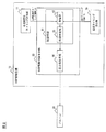
- FIG. 1 is a conceptual diagram illustrating an example of use of an IABP driving device according to an embodiment of the present invention.
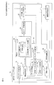
- FIG. 2 is a schematic block diagram of the IABP driving device shown in FIG.
- FIG. 3 is a flowchart showing an example of processing in IABP performed by the IABP driving device shown in FIG.
- FIG. 4 is a schematic block diagram showing an electrocardiogram signal timing calculation unit included in the IABP driving device shown in FIG.
- FIG. 5 is a flowchart showing an example of processing performed in ECG signal timing information calculation (step S004) in FIG.
- FIG. 6 is a schematic block diagram showing a blood pressure timing calculation unit included in the IABP driving device shown in FIG. FIG.
- FIG. 7 is a flowchart showing an example of processing performed in blood pressure timing information calculation (step S005) in FIG.
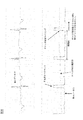
- FIG. 8 is a graph showing an example of third data and fourth data acquired and calculated by the electrocardiogram timing calculation unit shown in FIG.
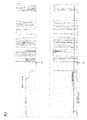
- FIG. 9 is a graph showing another example of the third data and the fourth data acquired and calculated by the electrocardiogram timing calculation unit shown in FIG.
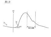
- FIG. 10 is a conceptual diagram showing the start point detection process performed by the start point detection unit in the blood pressure timing calculation unit shown in FIG.
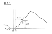
- FIG. 11 is a conceptual diagram showing the start point determination process performed by the start point detection unit in the blood pressure timing calculation unit shown in FIG. FIG.
- FIG. 12 is a conceptual diagram illustrating processing performed by the determination unit and the BP inflation / deflation timing calculation unit in the blood pressure timing calculation unit illustrated in FIG.
- FIG. 13 is a conceptual diagram showing an instantaneous difference determination process performed by the systolic pattern recognition unit in the blood pressure timing calculation unit shown in FIG.
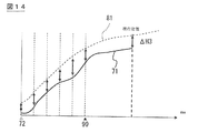
- FIG. 14 is a conceptual diagram illustrating a cumulative difference determination process performed by the systolic pattern recognition unit in the blood pressure timing calculation unit illustrated in FIG.
- FIG. 15 is a conceptual diagram illustrating an example of a calculation process performed by the BP inflation / deflation timing calculation unit in the blood pressure timing calculation unit illustrated in FIG. 6.
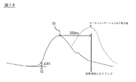
- FIG. 16 is a conceptual diagram illustrating an example of calculation processing performed by the data management unit in the blood pressure timing calculation unit illustrated in FIG.
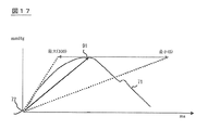
- FIG. 17 is a conceptual diagram illustrating another example of the arithmetic processing performed by the data management unit in the blood pressure timing calculation unit illustrated in FIG.
- FIG. 18 is a conceptual diagram illustrating an example of a calculation process performed by the delay time calculation unit in the blood pressure timing calculation unit illustrated in FIG.
- FIG. 19 is a flowchart illustrating an example of processing performed in the trigger synchronization determination (step S006) in FIG.
- FIG. 20 is a conceptual diagram illustrating normal driving and detection driving performed by the IABP driving device shown in FIG.
- FIG. 21 is a conceptual diagram showing the necessity of the start point check process performed by the start point detection unit shown in FIG.
- FIG. 1 is a conceptual diagram showing an example of use of an IABP driving device 10 according to an embodiment of the present invention.
- the IABP drive device 10 includes an electrocardiogram signal timing calculation unit 11, a blood pressure timing calculation unit 70, and an IABP drive control main body unit 60.
- the electrocardiogram signal timing calculation unit 11 calculates the electrocardiogram signal timing information 55 related to the drive timing of the balloon 68 that is the driven device, and outputs it to the IABP drive control main body unit 60.
- the electrocardiogram signal timing calculation unit 11 can acquire an electrocardiogram signal representing the electrical activity of the heart in the implementation target via the electrode 14 attached to the human body or the like that is the implementation target of the IABP.
- the electrocardiogram signal timing calculation unit 11 may be integrated with the IABP drive control main body 60 that performs drive control of the balloon 68, or may be removed from the IABP drive control main body 60 and used as a timing detection device. good. Details of the electrocardiogram signal timing calculation unit 11 will be described later in detail with reference to FIGS. 4, 5, 8 and 9.
- the blood pressure timing calculation unit 70 calculates blood pressure timing information 75 related to the driving timing of the balloon 68 based on the blood pressure fluctuation data, and outputs the blood pressure timing information 75 to the IABP drive control main body 60.
- the blood pressure timing calculation unit 70 can acquire arterial pressure fluctuation information via an optical sensor, a pressure transducer, or the like, but the blood pressure fluctuation acquisition method is not particularly limited. Details of the blood pressure timing calculation unit 70 will be described later in detail with reference to FIGS. 6, 7, and 10 to 18.
- the IABP drive control main body 60 receives information related to the drive timing of the balloon 68 from the electrocardiogram signal timing calculation unit 11 and the blood pressure timing calculation unit 70, and performs IABP based on these information.
- FIG. 2 is a schematic block diagram showing the overall configuration of the IABP driving device 10. As shown in FIG. 2, the IABP drive control main body 60 includes a pressure generation unit 66 and a control unit 61.
- the pressure generating means 66 alternately applies positive pressure and negative pressure to the piping system communicating with the balloon 68 so that the balloon 68 repeats expansion and contraction due to the flow of a driving fluid such as helium gas.
- the control means 61 controls the pressure generating means 66 based on the electrocardiogram signal timing information 55 and the blood pressure timing information 75 so that the balloon 68 is inflated / deflated in synchronization with a predetermined timing of the heart beat cycle.
- the control means 61 has a receiving unit 62 and a synchronization determining unit 65.
- the receiving unit 62 receives the electrocardiogram signal timing information 55 and the blood pressure timing information 75.
- the synchronization determination unit 65 determines which of the electrocardiogram signal timing information 55 and the blood pressure timing information 75 is used to control the pressure generating unit 66.
- the control unit 61 is described using an example in which the synchronization determination unit 65 selects either one of the electrocardiogram signal timing information 55 and the blood pressure timing information 75 to control the pressure generation unit 66.
- the control method of the pressure generating means 66 by the control means 61 is not limited to this.
- the control unit 61 may control the pressure generating unit 66 using both the electrocardiogram signal timing information 55 and the blood pressure timing information 75.
- FIG. 3 is a flowchart showing an example of processing in IABP performed by the IABP driving apparatus 10 shown in FIG.
- step S001 the IABP driving device 10 is activated.
- step S001 or in step S001 as shown in FIG. 1, the electrode 14, the balloon 68, etc. are arrange
- step S002 of FIG. 3 the IABP drive control main body 60 shown in FIG. 2 acquires information necessary for future IABP drive and performs setting as necessary.
- the control means 61 acquires the input information of the operator via the operation unit or the like, and the synchronization determination unit 65 can appropriately hold the electrocardiogram signal timing information 55 and the blood pressure timing information 75 to be input in the future. Set the data holding area.
- step S003 of FIG. 3 the IABP drive control main body 60 shown in FIG. 2 performs auto timing setting.
- the IABP drive control main body 60 first sets whether to perform IABP at manual timing or at auto timing.
- the IABP drive control main body 60 shifts to the manual mode when obtaining information that the operator has selected the manual mode for performing IABP at the manual timing.
- the IABP drive control main body 60 when obtaining information indicating that the operator has selected auto timing, the IABP drive control main body 60 further requests input from the operator or communicates with the electrocardiogram signal timing calculation unit 11 and the blood pressure timing calculation unit 70. Acquire and set information necessary for auto timing. For example, the IABP drive control main body 60 acquires information such as a device used for acquiring an electrocardiogram signal and blood pressure fluctuation data, and sets a priority order when using the input information as necessary. To do.
- the electrocardiogram signal timing calculation unit 11 of the IABP driving apparatus 10 illustrated in FIG. 2 calculates the electrocardiogram signal timing information 55.
- the calculation process (step S004) of the electrocardiogram signal timing information 55 will be described in detail with reference to FIG. 4, FIG. 5, FIG. 8, FIG.
- FIG. 4 is a schematic block diagram showing the internal configuration of the electrocardiogram signal timing calculation unit 11 shown in FIG. 2, and FIG. 5 shows the detailed processing of the calculation process (step S004) of the electrocardiogram signal timing information 55 shown in FIG. It is a flowchart.
- the electrocardiogram signal timing calculation unit 11 includes a third data acquisition unit 16, a fourth data calculation unit 20, an R wave timing detection unit 24, a noise determination unit 30, a storage unit 40, and an ECG average value calculation unit. 42, an abnormality detection unit 50, and an ECG expansion / contraction timing calculation unit 52.
- the third data acquisition unit 16 illustrated in FIG. 4 acquires the third data 18.
- the 3rd data acquisition part 16 can acquire the 3rd data 18 by performing A / D conversion etc. with respect to the electrocardiogram signal 12 input via the electrode 14 (refer FIG. 1). .
- the third data acquisition unit may acquire the third data 18 by receiving the third data 18 from the outside of the IABP driving device 10.
- the third data acquisition unit 16 may include a memory that temporarily stores the third data 18.
- the third data acquisition unit 16 outputs the acquired third data 18 to the fourth data calculation unit 20.
- the fourth data calculation unit 20 illustrated in FIG. 4 calculates the fourth data 22 obtained by applying the second variation method to the third data 18.
- the fourth data calculation unit 20 calculates the fourth data 22 using the following mathematical formula (1), which is an example of a calculation formula for the second variational method.
- a (t) (V (t) ⁇ V (t ⁇ )) ⁇ (V (t ⁇ ) ⁇ V (t ⁇ ⁇ 2)) ⁇ (V (t ⁇ ) ⁇ V (T ⁇ 2 ⁇ ⁇ )) ⁇ (V (t ⁇ ) ⁇ V (t ⁇ )) Equation (1)
- Equation (1) A (t) is the value of the fourth data 22 at time t
- V (t) is the value of the third data 18 at time t
- ⁇ and ⁇ are time delays.
- FIG. 8 shows the third data 18 acquired by the third data acquisition unit 16 and the fourth data 22 calculated by the fourth data calculation unit 20 with the same time.
- the upper graph in FIG. 8 represents the third data 18.
- the third data 18 corresponds to an electrocardiogram signal representing the electrical activity of the heart, and the vertical axis is mV.
- the sampling period of the third data 18 is not particularly limited, but can be set to about 0.5 to 2.0 ms, for example.
- the lower graph (solid line) in FIG. 8 represents the fourth data 22 calculated by applying the above formula (1) to the third data 18.
- an electrocardiogram waveform can be understood from the fact that the amount of change of the third data 18 (V (t)) accompanying the time change of the delay time ⁇ is multiplied (see equation (1)).
- the calculated value A (t) fluctuates greatly depending on whether the time variation of the third data 18 is rapid or moderate.
- the fourth data calculation unit 20 can acquire the fourth data 22 in which a predetermined peak included in the electrocardiogram signal is emphasized by appropriately setting the time delays ⁇ and ⁇ .
- the fourth data calculation unit 20 sets the delay times ⁇ and ⁇ so as to emphasize the R wave (change in QRS) in the electrocardiogram signal.
- Specific values of time delays ⁇ and ⁇ are adjusted according to the measurement target and are not particularly limited. For example, ⁇ may be 17 ms and ⁇ may be 11 ms.
- the calculated value of the fourth data 22 calculated by the fourth data calculating unit 20 is an abstracted value.
- the vertical axis (calculated value) is higher than the third data 18 in the portion of the R wave (QRS) where the steepest value change occurs in the electrocardiogram signal (waveform). It can be seen that the change is emphasized.
- the fluctuation of the baseline of the electrocardiogram signal and other waveforms such as a P wave and a T wave show a gradual change in the third data 18 as compared with the R wave. Therefore, in the fourth data 22 calculated by the fourth data calculation unit 20, the baseline fluctuation of the electrocardiogram signal, the P wave, and the T wave are weakened in the relative comparison with the R wave.
- the fourth data calculation unit 20 may perform a calculated value peak cut when the value calculated by the mathematical formula (1) exceeds a predetermined value. . This is because it is sufficient that the portion corresponding to the R wave can be clearly distinguished from the other portions in the processing by the electrocardiogram signal timing calculation unit 11. As shown in FIG. 4, the fourth data calculation unit 20 outputs the calculated fourth data 22 to the R wave timing detection unit 24 and the noise determination unit 30.
- the noise determination unit 30 illustrated in FIG. 4 determines the amount of noise included in the electrocardiogram signal.
- the noise determination unit 30 determines the amount of noise included in the electrocardiogram signal using the fourth data 22 calculated by the fourth data calculation unit 20, and if it is determined that there is a lot of noise, R-wave timing detection A stop signal 32 for stopping timing detection is output to the unit 24.
- the noise determination unit 30 can also perform noise determination based on the third data 18 corresponding to the electrocardiogram signal. However, as shown in FIG. 4, the noise determination unit 30 preferably performs noise determination using the fourth data 22 in the same manner as the R wave timing detection unit 24 from the viewpoint of preventing erroneous detection. This is because the noise mixed in the electrocardiogram signal may have a steep change that is easily emphasized by the second variational method.
- FIG. 9 shows another example of the third data 18 and the fourth data 22.
- the upper graph in FIG. 9 represents the third data 18, and the lower graph represents the fourth data 22.
- the noise determination unit 30 aggregates whether or not the calculated value of the fourth data 22 exceeds a preset threshold for noise detection. Then, when the ratio of the calculated value of the fourth data 22 exceeding the noise detection threshold during a predetermined counting time (for example, 750 ms) becomes a certain value (for example, 60%) or more, the noise determination unit 30. It can be determined that there is a lot of noise in the electrocardiogram signal.
- the noise determination unit 30 recognizes that the ratio of the calculated value of the fourth data 22 that exceeds the noise detection threshold after the time t ⁇ b> 1 is greater than or equal to a certain value, and the R wave timing detection unit 24. In response to this, a stop signal 32 for stopping timing detection is output.
- the R-wave timing detection unit 24 that has received the stop signal 32 can reduce erroneous detection of timing by temporarily stopping timing detection.
- the R wave timing detection unit 24 shown in FIG. 4 detects the timing of the R wave in the electrocardiogram signal using the fourth data 22.
- the R wave timing detection unit 24 includes a reference value calculation unit 26 and a comparison unit 28.
- the reference value calculation unit 26 calculates an R trigger determination threshold 25 (see FIG. 8) that is a reference value for detecting an R wave.
- the reference value calculation unit 26 may set the trigger determination threshold based on input by the user of the apparatus, and may use a fixed value determined by a predetermined condition as the trigger determination threshold. In the example shown in FIG. The reference value calculation unit 26 calculates the R trigger determination threshold 25 using the fourth data 22 calculated by the fourth data calculation unit 20.
- the reference value calculation unit 26 acquires the maximum value of the fourth data 22 within a certain time (for example, a time including one heartbeat), and several tens percent (for example, about 40%) of the maximum value. ) Is the R trigger determination threshold 25. In this way, by calculating the R trigger determination threshold 25 based on the actually acquired fourth data 22, even when the acquired ECG signal and the amplitude of the third data 18 change, the timing Misdetection and false detection can be prevented.
- the calculation method of the R trigger determination threshold 25 in the reference value calculation unit 26 is not limited to the above-described method.
- the maximum value of the fourth data 22 used for calculating the R trigger determination threshold 25 is a plurality of maximum values. May be an average value.
- Correction may be performed so as to decrease the R trigger determination threshold 25.
- the R trigger determination threshold value 25 calculated by the reference value calculation unit 26 is output to the comparison unit 28.
- the comparison unit 28 in the R-wave timing detection unit 24 mainly detects the R-wave timing (particularly the R-wave rise timing) in the electrocardiogram signal.
- the comparison unit 28 compares the fourth data 22 shown in FIG. 4 with the R trigger determination threshold 25, and whether the fourth data 22 is equal to or greater than the R trigger determination threshold 25 or less than the R trigger determination threshold 25. Recognize
- the R wave timing detection unit 24 uses the comparison result of the comparison unit 28 to detect the timing at which the fourth data 22 is recognized as exceeding the R trigger determination threshold 25 as the R trigger detection timing.
- the R wave timing detection unit 24 has the latest calculated value of the fourth data 22 equal to or greater than the R trigger determination threshold 25 and the immediately preceding calculated value of the fourth data 22 is equal to or less than the R trigger determination threshold 25.
- the timing is detected as the R trigger detection timing.
- the timing at which it is recognized that the fourth data 22 has exceeded the R trigger determination threshold 25 has not passed a predetermined time (for example, 250 ms) from the immediately preceding R trigger detection timing, the R wave timing detection unit 24 The timing is excluded from the R trigger detection timing.
- the R-wave timing detection unit 24 outputs R-wave timing information 29 that is information related to the R trigger detection timing to the storage unit 40, the ECG expansion / contraction timing calculation unit 52, and the abnormality detection unit 50. .
- the storage unit 40 stores R wave timing information 29 (for example, an R trigger detection timing interval 44 (see FIG. 4)).
- step S106 in FIG. 5 the ECG average value calculation unit 42 shown in FIG. 4 reads the R trigger detection timing interval 44 from the storage unit 40, and calculates the RR average corresponding to the R wave detection cycle of the electrocardiogram signal. To do.
- the ECG average value calculation unit 42 can calculate the moving average of the R trigger detection timing intervals 44 (for example, the average value of the intervals 44 for the latest four times) as the RR average.
- the calculation method of the RR average by the ECG average value calculating unit 42 is not limited to the above-described method, and for example, the weighted average of the interval 44 of the R trigger detection timing may be the RR average.
- the ECG average value calculation unit 42 calculates the latest R trigger detection timing interval 44 read from the storage unit 40 and the RR average calculated immediately before. Ventricular extrasystole (PVC) may be detected by comparing the values.
- PVC Ventricular extrasystole
- the ECG average value calculation unit 42 is in the PVC state when the latest R trigger detection timing interval 44 read from the storage unit 40 is less than 70% of the RR average value calculated immediately before. Can be detected.
- step S107 shown in FIG. 5 the ECG inflation / deflation timing calculation unit 52 shown in FIG. 4 calculates an inflation timing for inflating the balloon 68 and a deflation timing for deflating the balloon 68. More specifically, the expansion timing calculated here is a timing at which the pressure generating means 66 of the IABP drive control main body 60 applies a positive pressure to the piping system for transmitting the pressure to the balloon 68, and the contraction The timing is a timing at which the pressure generating means 66 applies a negative pressure to the piping system.
- the ECG expansion / contraction timing calculation unit 52 calculates the expansion timing and the contraction timing based on the R wave timing information 29 detected by the R wave timing detection unit 24 and the RR average calculated by the ECG average value calculation unit 42. Can be calculated.
- the specific calculation method in the ECG expansion / contraction timing calculation unit 52 is not particularly limited.
- the ECG expansion / contraction timing calculation unit 52 determines a predetermined ratio from the timing at which the R wave is detected to the RR average. The timing when the time multiplied by is further passed can be the expansion timing and the contraction timing.
- the abnormality detection unit 50 checks the abnormality of the electrocardiogram signal.
- the abnormality detection unit 50 detects an abnormality of the electrocardiogram signal when a predetermined time (for example, 10 seconds) has elapsed from the R trigger detection timing last detected by the R wave timing detection unit 24.
- the abnormality detection unit 50 also detects an abnormality in the electrocardiogram signal even when the third data 18 corresponding to the electrocardiogram signal has not changed over a predetermined time (for example, 3 seconds).
- the abnormality detection unit 50 can perform a warning operation to notify the user of the apparatus of the abnormality or output an abnormality detection signal to the IABP drive control main body unit 60.
- the electrocardiogram signal timing calculation unit 11 transmits the electrocardiogram signal timing information 55 to the control means 61 of the IABP drive control main body unit 60.
- the ECG signal timing information 55 includes the R wave timing information 29 detected by the R wave timing detection unit 24, the RR average calculated by the ECG average value calculation unit 42, and the ECG expansion / contraction timing calculation unit 52.
- Information calculated based on the electrocardiogram signal 12, such as the calculated inflation / deflation timing, and information related to the driving timing of the balloon 68 is included. Note that the transmission processing of the electrocardiogram signal timing information 55 does not need to be performed in a lump, and may be sequentially transmitted to the IABP drive control main body 60 when each piece of information is detected or calculated.
- the calculation processing of the electrocardiogram signal timing information 55 by the electrocardiogram signal timing calculation unit 11 ends.
- the electrocardiogram signal timing calculation unit 11 applies the second variation method to the third data 18 corresponding to the electrocardiogram signal, calculates the fourth data 22, and detects the timing of the R wave from the fourth data 22. . Since the rapid rise of the R wave is converted into the absolute value of the calculated value by the second variational method, the R wave (change in QRS) is easily separated from other parts of the electrocardiogram signal in the fourth data 22. Can be recognized separately. Therefore, the electrocardiogram signal timing calculation unit 11 can accurately detect the timing of the R wave and calculate accurate electrocardiogram signal timing information 55.
- step S005 the blood pressure timing calculation unit 70 in the IABP driving apparatus 10 shown in FIG. Note that either the calculation process of the electrocardiogram signal timing information 55 (step S004) or the calculation process of the blood pressure timing information 75 (step S005) may be performed first, or both processes are performed simultaneously. May be.
- FIG. 6 is a schematic block diagram showing the internal structure of the blood pressure timing calculation unit 70 shown in FIG. 2
- FIG. 7 is a flowchart showing detailed processing of the blood pressure timing information 75 calculation processing (step S005) shown in FIG. is there.
- the blood pressure timing calculation unit 70 calculates blood pressure timing information 75 related to the driving timing of the balloon 68 based on blood pressure fluctuation data. As shown in FIG. 6, the blood pressure timing calculation unit 70 includes a first data acquisition unit 74, a second data storage unit 84, a determination unit 86, and a BP inflation / deflation timing calculation unit 92. The blood pressure timing calculation unit 70 includes a start point detection unit 76, a data management unit 78, an interval storage unit 94, a BP average value calculation unit 95, a delay time calculation unit 96, and the like.
- the first data acquisition unit 74 illustrated in FIG. 2 acquires first data 71 corresponding to blood pressure fluctuation.
- the first data acquisition unit 74 can acquire the first data 71 by performing A / D conversion or the like on a signal input to the blood pressure timing calculation unit 70 via an optical sensor or a pressure transducer. . Further, the first data acquisition unit 74 may acquire the first data 71 by receiving the first data 71 from the outside of the blood pressure timing calculation unit 70.
- the first data acquisition unit 74 can continuously acquire the first data 71 at a sampling interval of, for example, about 1 ms, but the sampling interval when acquiring the first data 71 is not particularly limited.
- the first data acquisition unit 74 outputs the acquired first data 71 to the start point detection unit 76.
- FIG. 10 is a conceptual diagram showing the start point detection process by the start point detection unit 76.
- the start point detection unit 76 detects an increase in blood pressure accompanying the start of the systole from the first data 71 and sets it as the first start point 72. More specifically, the start point detection unit 76 holds the minimum value of the first data 71 after a predetermined reset timing (the R wave timing 97 in the electrocardiogram waveform in FIG. 10), and the held minimum value and the current When the blood pressure difference ⁇ H1 of the first data 71 becomes 5 mmHg or more, that point is set as a first start point 72.
- a predetermined reset timing the R wave timing 97 in the electrocardiogram waveform in FIG. 10
- the start point detection unit 76 does not perform the detection process of the first start point 72 during the period in which the balloon 68 is inflated in order to avoid erroneous detection (see the exclusion period in FIG. 10). ).
- the reset timing for detecting the start point is the R-wave timing 97, but the reset timing is not limited to this.
- the point in time when the first start point 72 is discarded and the combination thereof can be set as the reset timing.
- step S203 shown in FIG. 7 the start point detection unit 76 correctly detects the rising period of blood pressure accompanying the start of the systole for the first start point 72 detected in step S202. Check if it exists.
- the start point detection unit 76 performs the start point check process until the time ⁇ t3 after detecting the first start point 72 reaches 100 ms (see FIG. 11).
- the start point detection unit 76 detects that the first start point 72 and the blood pressure value after detection of the first start point 72 are out of a predetermined range, or the holding time of the minimum value that is a reference for detection is long. If the balloon 68 is inflated at the time of the first start point 72 or if the blood pressure fluctuation exceeds a predetermined range after the first start point 72 is detected, the detected first start point 72 is detected. Is discarded. When the start point is discarded in step S203, the start point detection unit 76 returns to step S202 and detects the first start point 72.
- FIG. 21 is a conceptual diagram illustrating the necessity of the start point check process performed by the start point detection unit 76 in step S203.
- the start point detection unit 76 sets a timing that is not an increase period of blood pressure accompanying the start of the systole.
- the first start point 72 may be detected by mistake.
- the start point check unit 76 erroneously detects the timing that is not in the rise period of the blood pressure accompanying the start of the systole as the first start point 72 due to the disturbance of the blood pressure waveform or the like by the start point check process, In addition, such detection points can be discarded and erroneous detection can be suppressed.
- step S204 in FIG. 7 the start point detection unit 76 performs a necessary check and then determines the first start point 72.
- FIG. 11 is a conceptual diagram illustrating a start point determination process performed by the start point detection unit 76.
- the start point detection unit 76 performs the start point determination process when the time ⁇ t3 from when the first start point 72 is detected reaches 100 ms. Therefore, the condition for performing the process of step S204 is that the first start point 72 detected in step S202 is not discarded for 100 ms by the check process of step S203.
- step S204 the start point detection unit 76 firstly compares the blood pressure difference between the minimum value of blood pressure (blood pressure at the time 98 when blood pressure is minimum) and the current time (after 100 ms from the first start point 72) as a reference for detecting the first start point 72. It is checked whether ⁇ H2 is within a predetermined range (for example, 5 mm to 100 mmHg) (Check 1 at the time of determination). Furthermore, the start point detector 76 checks that the first data 71 from the first start point 72 to the current time does not contain excessive noise (check 2 at the time of determination).
- a predetermined range for example, 5 mm to 100 mmHg
- the start point detection unit 76 determines the first data from the first start point 72 to the current time. It can be determined that one data 71 contains excessive noise.
- the start point detection unit 76 has a short interval between the immediately preceding first start point and the current first start point 72 (for example, 500 ms or less), and the blood pressure value at the current first start point 72 is the immediately preceding value. It is checked that the blood pressure value at the first start point is not larger than a predetermined ratio (for example, 1.5 times) or more (check 3 at the time of confirmation). When these determination checks 1 to 3 are passed, the start point detection unit 76 determines the first start point 72. However, if the first data 71 from the first start point 72 to the present does not satisfy any of the conditions at the time of confirmation checks 1 to 3, the detected first start point 72 is discarded and the process proceeds to step S202. Return.
- the reason why the start point detector 76 performs the final check 1 to 3 is that the timing at which the blood pressure does not increase due to the start of the systole is erroneously detected as the first start point 72 as in the case of the start point check in step S203. This is to avoid this.
- the start point detection unit 76 illustrated in FIG. 6 uses the first data 71 as the first data 71 and information regarding the determined first start point 72 and the start point determination time 99 (at the time of blood pressure trigger), which is the time when the first start point 72 is determined. And output to the determination unit 86 and the data management unit 78. In addition, the start point detection unit 76 outputs information regarding the determined first start point 72 to the interval storage unit 94.
- the interval storage unit 94 and the BP average value calculation unit 95 of the blood pressure timing calculation unit 70 calculate the average interval of the first start points 72.
- the interval storage unit 94 stores the detection timing of the first start point 72 detected and confirmed by the start point detection unit 76.
- the BP average value calculation unit 95 calculates the average interval of the first start points 72 at the timing when the newly determined first start point 72 is output from the start point detection unit 76 or the like.
- the BP average value calculation unit 95 reads the detection timing of the past first start point 72 stored in the interval storage unit 94 and calculates the average interval of the first start points 72.
- the BP average value calculation unit 95 calculates the moving average of the intervals of the first start points 72 (for example, the average value of the intervals of the first start points 72 for the latest four times) as the average interval of the first start points 72.
- the calculation method of the average interval by the BP average value calculation unit 95 is not limited to the method described above, and for example, a weighted average of the intervals of the first start points 72 may be used as the calculation value.
- the interval storage unit 94 and the BP average value calculation unit 95 calculate the average interval of the start point determination time 99 with reference to the start point determination time 99 (at the time of blood pressure trigger) instead of the average interval of the first start point 72. You may ask.
- the BP average value calculation unit 95 may detect ventricular extrasystole (PVC) in addition to calculating the average value.
- the average interval calculated by the BP average value calculation unit 95 corresponds to a heartbeat cycle. When the interval between the current and previous first start points 72 is significantly shorter than the average interval so far, ventricular extrasystole ( It can be recognized that PVC) is occurring.
- the BP average value calculation unit 95 can detect that the current state is the PVC state when the interval between the current and previous first start points 72 is less than 70% of the average interval until then.
- the determination unit 86 in FIG. 6 determines the similarity between the first data 71 received from the start point detection unit 76 and the second data 81 read from the second data storage unit 84. to decide. Similar to the first data 71, the second data storage unit 84 stores second data 81 corresponding to blood pressure fluctuations. The second data storage unit 84 stores a plurality of second data 81 having different waveform shapes, and the determination unit 86 can refer to the plurality of second data 81 for comparison with the first data 71. .
- the second data 81 stored in the second data storage unit 84 corresponds to blood pressure fluctuations in a predetermined section, and the predetermined section can be about 1 to 2 heartbeat cycles, but is not particularly limited. .
- the length of the second data 81 may be less than one heartbeat period, but the second data 81 preferably includes a dichroic notch. This is because when the second data 81 includes a dichroic notch, the information regarding the dichroic notch can be supplemented to the first data 71 even when the first data 71 does not have a dichroic notch.
- the second data storage unit 84 may store a plurality of second data 81 in advance regardless of the acquisition of the blood pressure waveform by the first data acquisition unit 74, but the second data storage unit 84 includes the first data storage unit 84. A part of the first data 71 acquired by the data acquisition unit 74 may be stored as the second data 81. More specifically, the data management unit 78 shown in FIG. 6 manages the second data 81 of the second data storage unit 84 and updates the data as necessary. The processing performed by the data management unit 78 is as follows. This will be described in step S210.
- the determination unit 86 illustrated in FIG. 6 is based on the pattern recognition unit 87 that calculates the similarity between the first data 71 and the second data 81 by a method such as pattern recognition, and the similarity calculated by the pattern recognition unit 87. And a second data extraction unit 90 that extracts second data 81 similar to the first data 71.
- the pattern recognizing unit 87 mainly includes a prebeat comparing unit 88 that determines similarity using numerical values representative of the entire one heartbeat cycle (heartbeat cycle, systolic blood pressure value, diastolic blood pressure value, etc.), and mainly systolic contraction.
- a systolic pattern recognition unit 89 that determines similarity using only data corresponding to the period.
- step S206 in FIG. 7 the preceding beat comparison unit 88 shown in FIG. 6 roughly determines the similarity between the first data 71 and the second data 81, and candidates for the second data 81 for which detailed determination is made in step S207. Is selected.
- the prebeat comparison unit 88 is set to a cycle immediately before the heartbeat cycle currently in progress (corresponding to one beat immediately before the systole including the first start point 72 determined in step S204). It is possible to use indices such as the wavelength (heart rate), the systolic blood pressure value, the diastolic blood pressure value, and the timing to reach the systolic blood pressure value.
- the anterior beat comparing unit 88 is similar to the first data 71 in that the wavelength (heart rate), the maximum blood pressure value, the minimum blood pressure value, An index such as the timing of reaching the hypertension value can be used.
- the previous beat comparison unit 88 sets the second wavelength (heart rate cycle) and the like related to the previous cycle for the two beats.
- the portion related to the posterior period used as a feature of the data 81 is used in a systolic pattern recognition (step S207) described later.
- the anterior beat comparison unit 88 compares the characteristics of the first data 71 and the second data 81 described above, and determines that the difference is within a predetermined range as a candidate for performing systolic pattern recognition in step S207. Select.
- the determination unit 86 performs screening (step S206) using the characteristics of the previous beat before performing systolic pattern recognition (step S207), which will be described later, thereby reducing the amount of calculation of the determination unit 86 and similarity. The accuracy of sex determination can be increased.
- FIG. 12 is a conceptual diagram illustrating processing performed by the determination unit 86 including the systolic pattern recognition unit 89 and the BP expansion / contraction timing calculation unit 92.
- the systolic pattern recognition unit 89 compares the first data 71 from the first start point 72 to the current time with the second data 81 after the second start point 82, and compares the first data 71 and the second data 81. Judge similarity. Note that the second start point 82 of the second data 81 is the same as the first start point 72 of the first data 71, in which the blood pressure rise period associated with the start of the systole period is detected.
- the start point determination unit 76 performs the start point determination process (step S204) 100 ms after the first start point 72 is detected in step S202 ( ⁇ t3)
- the systolic pattern At the time of performing the recognition process, the first data 71 of at least 100 ms ( ⁇ t3) from the first start point 72 is acquired. Accordingly, the systolic pattern recognition unit 89 determines similarity between the first data 71 at least between the first start point 72 and 100 ms and the second data 81 (100 ms from the second start point 82) corresponding thereto. It can be used as information for determination.
- the second data 81 used by the systolic pattern recognition unit 89 to determine similarity it is preferable to use the data selected in the prebeat comparison process described in step S206 (see FIG. 7).
- the systolic pattern recognition unit 89 can determine the similarity of each of the plurality of second data 81 with the first data 71 and output the result. Furthermore, if the first systolic pattern recognition unit 89 can acquire the first data 71 after the start point determination time 99 (100 ms from the first start point 72), the first data 71 after the start point determination time 99 and The second data 81 corresponding to this can be used as information for determining similarity.
- the method used when the systolic pattern recognition unit 89 determines the similarity between the first data 71 and the second data 81 is not particularly limited. For example, a correlation coefficient, an instantaneous difference, a cumulative difference, etc. An indicator can be used.
- the systolic pattern recognition unit 89 acquires the blood pressure value ai of the first data 71 and the blood pressure value bi of the second data 81 at 10 ms intervals, and uses the following formula (2) to The linear correlation coefficient r of the second data 81 can be obtained.
- the systolic pattern recognition unit 89 determines the similarity between the first data 71 and the second data 81 using the instantaneous difference between the first data 71 and the second data 81 as an index. You can also The systolic pattern recognition unit 89 determines whether or not there is a point between the first data 71 and the second data 81 where the instantaneous blood pressure difference ⁇ H4 is a predetermined value (for example, 20 mmHg) or more. Similarity can be judged by using whether it exists at a frequency.
- the systolic pattern recognition unit 89 determines the similarity between the first data 71 and the second data 81 using the cumulative difference between the first data 71 and the second data 81 as an index. You can also The systolic pattern recognition unit 89 obtains the blood pressure difference ⁇ H3 between the first data 71 and the second data 81 at an interval of 10 ms, and can determine similarity using the total or average value as an index.
- the second data extraction unit 90 shown in FIG. 6 changes from the second data 81 stored in the second data storage unit 84 to the first data 71 based on the determination result by the pattern recognition unit 87. Extract the most similar.
- the extraction method by the second data extraction unit 90 is not particularly limited. For example, each index calculated by the systolic pattern recognition unit 89 is within a predetermined range and the linear correlation coefficient r is closest to 1.
- a method of extracting the data 81 and a method of comprehensively judging and extracting the linear correlation coefficient r calculated by the systolic pattern recognition unit 89, the index based on the instantaneous difference, and the index based on the cumulative difference are cited. It is done.
- the second data extraction unit 90 of the determination unit 86 outputs information regarding the extracted second data 81 to the BP expansion / contraction timing calculation unit 92.
- the BP inflation / deflation timing calculation unit 92 calculates the inflation timing for inflating the balloon 68 and the deflation timing for deflating the balloon 68 based on the determination result of the determination unit 86 and the like. More specifically, the inflation / deflation timing calculated here is the same as the expansion / deflation timing calculated by the ECG inflation / deflation timing calculation unit 52, and the pressure generating means 66 of the IABP drive control main body 60 uses the balloon. This is the timing at which positive / negative pressure is applied to the piping system for transmitting pressure to 68.
- step S209 the BP inflation / deflation timing calculation unit 92 calculates the inflation timing of the balloon 68.
- the BP expansion / contraction timing calculation unit 92 reads the dichroic notch timing (D notch timing 83) included in the second data 81 extracted in step S208 from the second data storage unit 84, and currently proceeds. This is used to estimate the timing at which the middle systole ends and switches to the diastole (the timing of the dichroic notch in the current heart cycle at which the first start point 72 is detected).
- the BP inflation / deflation timing calculation unit 92 acquires the current heartbeat period (acquired).
- the interval from the first start point 72 to the dichroic notch in the second data 81 is estimated to be the same as the interval from the second start point 82 to the D notch timing 83 in the second data 81.
- the BP inflation / deflation timing calculation unit 92 sets the time calculated in consideration of the balloon inflation delay time ⁇ t 4 to the estimated D notch timing 83 as the inflation timing 93. Can do.
- the BP expansion / contraction timing calculation unit 92 performs a predetermined correction on the interval from the second start point 82 to the D notch timing 83 (
- the interval from the first start point 72 to the dichroic notch in the first data 71 is estimated by adding a correction value ⁇ D shown in FIG.
- the BP expansion / contraction timing calculation unit 92 calculates the pressure difference ⁇ A from the first start point 72 to the current time t5 and the pressure from the second start point 82 to the time corresponding to the current time t5.
- the correction value ⁇ D can be calculated in consideration of the difference ⁇ P, the time ⁇ t6 from the first start point to the D notch timing 83, and the time ⁇ t7 from the first start point to the current time t5. Also in this case, the BP inflation / deflation timing calculation unit 92 can set the time calculated in consideration of the balloon inflation delay time ⁇ t 4 to the estimated D notch timing 83 as the inflation timing 93.
- the second data 81 determined to be similar to the first data 71 by the determination unit 86 is also included in the first data 71 for portions other than the portion directly compared by the determination unit 86. This is because they are considered to be similar.
- the first start point 72 is a detection of the rise in blood pressure immediately after the start of the systole, and the similarity determination performed by the systole pattern recognition unit 89 is determined by the systole. Pattern recognition was performed on the waveform shape of the period.
- the time point when the timing is calculated by the BP expansion / contraction timing calculation unit 92 is the current time t5
- the BP expansion / contraction timing calculation unit 92 can acquire only the first data 71 up to the current time t5 at the maximum.
- the BP expansion / contraction timing calculation unit 92 shown in FIG. 6 uses the information of the second data 81 extracted by the second data extraction unit 90 to accurately determine the future timing occurring after the current time t3. Can be calculated.
- the expansion delay time ⁇ t4 may be a fixed value set at the start of IABP, or may be a fluctuation value updated by a predetermined method. A method for calculating the expansion delay time ⁇ t4 will be described in step S211. In addition, as shown in FIG.
- the contraction timing detection device 70 may repeat the process from the systolic pattern recognition (step S207) to the BP expansion / contraction timing calculation (step S209) after adding the first data 71.
- a predetermined length for example, 10 ms or more
- the contraction timing detection device 70 may repeat the process from the systolic pattern recognition (step S207) to the BP expansion / contraction timing calculation (step S209) after adding the first data 71.
- the systolic pattern recognition unit 89 can perform similarity determination using the first data from the middle to the latter half of the systole, and the timing estimation accuracy can be improved.
- the BP expansion / contraction timing calculation unit 92 uses the average interval calculated by the BP average value calculation unit 95. Thus, the expansion timing can be calculated. Further, the BP expansion / contraction timing calculation unit 92 calculates the contraction timing using the average interval calculated by the BP average value calculation unit 95. In this case, the BP expansion / contraction timing calculation unit 92 sets the timing when the time obtained by multiplying the average interval by a predetermined ratio from the first start point 72 or the start point determination time 99 as the expansion timing and the contraction timing. be able to.
- the data management unit 78 shown in FIG. 6 updates the second data 81 in the second data storage unit 84.
- the data management unit 78 includes a storage data extraction unit 79 and a storage data erasure unit 80.
- the stored data extraction unit 79 stores the second data 81 as the second data 81 from the first data 71 input via the first data acquisition unit 74 or the start point detection unit 76. Extract the part to be used.
- the stored data extraction unit 79 performs a predetermined time from when the peak (maximum value) of the blood pressure value is formed after the first start point 72 (at the time of the self-pressure maximum point 91 in FIG. 16). After a lapse of (for example, 250 ms), a predetermined check is performed on the first data 71. If the check is passed, the first data 71 is registered as the second data 81.
- Check items for registering the first data 71 as the second data 81 include that the blood pressure value of the first data 71 is within a predetermined range and the waveform length of the first data 71 is within a predetermined range. There are some things. As shown in FIG. 17, the stored data extraction unit 79 may use a check item that the slope from the first start point 72 to the self-pressure maximum point 91 is within a predetermined range.
- the stored data extraction unit 79 When the stored data extraction unit 79 registers the first data 71 that has passed the check in the second data storage unit 84 as the second data 81, the stored data extraction unit 79 can store related information in association with the second data 81. it can.
- the storage data extraction unit 79 stores information related to the first start point 72 of the first data 71 that is the basis of the second data 81 to be registered as information related to the second start point 82 of the second data 81. be able to.
- the storage data extraction unit 79 includes information on the dichroic notch included in the second data 81 to be registered (for example, an interval from the second start point 82 to the dichroic notch), information on the self-pressure maximum point 91, and the like. It can be memorized.
- step S210 the stored data erasure unit 80 erases unnecessary or less important data among the second data 81 stored in the second data storage unit 84.
- the stored data erasure unit 80 can erase the second data 81 that has never been extracted by the second data extraction unit 90 even after a predetermined time has elapsed.
- the blood pressure timing detection device 70 updates the second data 81 in the second data storage unit 84 by the data management unit 78, thereby determining the probability that the determination unit 86 can extract the second data 81 similar to the first data 71. Can be increased. Thereby, the blood pressure timing detection device 70 can perform accurate timing detection. Further, the data management unit 78 manages the second data 81 stored in the second data storage unit 84, thereby reducing the storage capacity required for the second data storage unit 84. The processing burden can be reduced. The data management unit 78 may classify the second data 81 into a plurality of groups based on information on the waveform shape and the like, and store and manage the second data 81 in the second data storage unit 84 for each group. By managing the second data 81 stored in the second data storage unit 84 in groups, the determination process by the determination unit 86 is made more efficient and the storage capacity required for storing the second data 81 is suppressed. Is possible.
- the delay time calculation unit 96 in FIG. 6 calculates the expansion delay time ⁇ t4.
- the delay time calculation unit 96 stores the first data 71 for a predetermined time (for example, 20 ms to 150 ms) after the expansion timing, which is the timing at which the pressure generating means 66 applies a positive pressure to the piping system. Monitoring is performed to detect a change point 85 where the slope of the first data 71 changes from falling to rising. Further, the delay time calculation unit 96 calculates the expansion delay time ⁇ t4 based on the time from the expansion timing to the change point 85, and outputs it to the BP expansion / contraction timing calculation unit 92.
- the delay time calculation unit 96 may use the time from the expansion timing to the change point 85 itself as the expansion delay time ⁇ t4, but may also use the moving average value of the time from the expansion timing to the change point 85 as the expansion delay time ⁇ t4. good. Further, the delay time calculation unit 96 may calculate not only the inflation delay time ⁇ t4 but also the delay time until the blood pressure fluctuation effect actually occurs from the contraction timing.
- the blood pressure timing calculation unit 70 transmits the blood pressure timing information 75 to the control means 61 of the IAPB drive control main body unit 60.
- the blood pressure timing information 75 includes an average interval calculated by the BP average value calculation unit 95, an expansion / deflation timing calculated by the BP expansion / deflation timing calculation unit 92, and a first start determined by the start point detection unit 76. Information calculated based on the first data 71 corresponding to the blood pressure fluctuation, such as the point 72 or the start point determination time 99, and information related to the drive timing is included.
- the transmission processing of the blood pressure timing information 75 does not need to be performed at once, and is sequentially transmitted to the IABP drive control main body 60 when each information is detected or calculated. Also good.
- the blood pressure timing calculation unit 70 calculates blood pressure timing information 75 (step S005 in FIG. 3).
- the blood pressure timing calculation unit 70 uses not only a current blood pressure fluctuation waveform (first data 71) but also a past blood pressure fluctuation waveform (second data) similar to the current blood pressure fluctuation waveform by using a determination method such as pattern recognition. 81) can be used to calculate timing. More specifically, as shown in FIG. 12, the blood pressure timing detection device 70 detects a rise in blood pressure accompanying the start of the systole as a first start point 72, and the blood pressure waveforms in the systole are similar. The second data 81 is used to estimate the timing of the dichroic notch.
- the blood pressure timing calculation unit 70 can accurately estimate future waveform fluctuations using the past blood pressure fluctuation waveform information similar to the current blood pressure fluctuation waveform, and accurately calculate the inflation / deflation timing. it can.
- the dichroic notch is a peak that occurs at the timing when the systole ends and switches to the diastole, so the timing is closely related to the blood pressure waveform of the immediately preceding systole, By performing pattern recognition using the systolic blood pressure waveform, it is possible to improve the timing calculation accuracy.
- step S006 shown in FIG. 3 the control means 61 of FIG. 2 performs trigger synchronization determination.
- the control unit 61 includes a receiving unit 62 and a synchronization determining unit 65.
- the receiving unit 62 receives the electrocardiogram signal timing information 55 from the electrocardiogram signal timing calculation unit 11 and the blood pressure timing information 75 from the blood pressure timing calculation unit 70.
- step S006 the synchronization determination unit 65 of the control unit 61 determines a control method of the pressure generation unit 66 based on the electrocardiogram signal timing information 55 and the blood pressure timing information 75 received by the reception unit 62.
- FIG. 19 is a flowchart illustrating an example of processing performed in the trigger synchronization determination (step S006) in FIG.
- step S301 of FIG. 19 the synchronization determination unit 65 checks whether or not the blood pressure timing information 75 is normal.
- the synchronization determination unit 65 checks whether the inflation / deflation timing included in the blood pressure timing information 75 is a normal value, whether the blood pressure timing information 75 is not input for a predetermined time (for example, 3 seconds), or the like. .
- the synchronization determination unit 65 proceeds to step S302 and employs the blood pressure timing information 75 as information for controlling the pressure generating means 66.
- the control means 61 controls the pressure generating means 66 based on the inflation / deflation timing calculated by the blood pressure timing calculation unit 70 in step S007 of FIG.
- step S301 if it is determined in step S301 that the blood pressure timing information 75 is not normal, the synchronization determination unit 65 proceeds to step S303 and checks whether the electrocardiogram signal timing information 55 is normal.
- step S303 the synchronization determination unit 65 is in a state where the expansion / contraction timing included in the electrocardiogram signal timing information 55 is a normal value, or the electrocardiogram signal timing information 55 is not input for a predetermined time (for example, 3 seconds) or longer. Check if there is any.
- the synchronization determination unit 65 proceeds to step S304, and adopts the electrocardiogram signal timing information 55 as information for controlling the pressure generating means 66.
- control means 61 controls the pressure generating means 66 based on the expansion / contraction timing calculated by the electrocardiogram signal timing calculation unit 11 in step S007 of FIG.
- the synchronization determination unit 65 ends the process as it is.
- the control means 61 controls the pressure generating means 66 based on the expansion / contraction timing employed in the trigger synchronization determination process of step S006.
- the control means 61 shown in FIG. 2 gives priority to the blood pressure timing information 75 when both the electrocardiogram signal timing information 55 and the blood pressure timing information 75 are normally input by the processing of the synchronization determination unit 65 as shown in FIG. To use.
- the blood pressure timing information 75 is calculated with reference to information included in past blood pressure fluctuation data (second data 81) having a predetermined time width, the timing calculation accuracy is high.
- the control means 61 can optimize the control of the pressure generating means 66 by using this with priority.
- the IABP driving apparatus 10 shown in FIG. 2 can perform IABP at auto timing by repeating steps S004 to S007 shown in FIG. Further, when a stop signal or the like is input, the IABP drive device 10 proceeds to step S008 in FIG. 3 and ends the IABP drive control.
- the IABP driving apparatus 10 acquires both the electrocardiogram signal timing information 55 calculated based on the electrocardiogram signal and the blood pressure timing information 75 calculated based on the blood pressure fluctuation data. Moreover, the blood pressure timing information 75 is calculated with high accuracy using pattern recognition, and the electrocardiogram signal timing information 55 is calculated with high accuracy using the second variational method. Therefore, the IABP driving device 10 can suppress trigger detection failure and detection error, and can highly optimize the expansion / contraction timing.
- the IABP driving device 10 not only performs normal driving for inflating the balloon 68 at the start of diastole a1 (dichroic notch) but also at a timing a2 delayed from the start of diastole.
- the detection drive for inflating may be performed at a predetermined frequency.
- the dichroic notch is too close to or overlaps with the blood pressure fluctuation accompanying the inflation of the balloon 68, so the blood pressure timing calculation unit 70 obtains the first data 71 including the dichroic notch. It becomes difficult to store this as the second data 81.
- the dichroic notch and the blood pressure fluctuation associated with the inflation of the balloon 68 are separated, whereby the second data storage unit 84 New second data 81 including a dichroic notch can be stored.
- the block diagram showing the internal configuration of the IABP driving device 10 shown in FIGS. 2, 4, and 6 is a conceptual diagram for explaining the processing in the IABP driving device 10.
- the processing may be performed using a central processing unit (CPU) or may be performed by combining a plurality of arithmetic circuits.
- CPU central processing unit
Landscapes
- Health & Medical Sciences (AREA)
- Engineering & Computer Science (AREA)
- Heart & Thoracic Surgery (AREA)
- Life Sciences & Earth Sciences (AREA)
- Cardiology (AREA)
- Veterinary Medicine (AREA)
- Animal Behavior & Ethology (AREA)
- Public Health (AREA)
- Biomedical Technology (AREA)
- General Health & Medical Sciences (AREA)
- Mechanical Engineering (AREA)
- Anesthesiology (AREA)
- Hematology (AREA)
- Medical Informatics (AREA)
- Vascular Medicine (AREA)
- Physics & Mathematics (AREA)
- Surgery (AREA)
- Molecular Biology (AREA)
- Pathology (AREA)
- Biophysics (AREA)
- Physiology (AREA)
- Transplantation (AREA)
- Psychiatry (AREA)
- Signal Processing (AREA)
- Computer Vision & Pattern Recognition (AREA)
- Artificial Intelligence (AREA)
- Measuring Pulse, Heart Rate, Blood Pressure Or Blood Flow (AREA)
- External Artificial Organs (AREA)
- Measurement And Recording Of Electrical Phenomena And Electrical Characteristics Of The Living Body (AREA)
Description
本発明は、医療等に用いられるタイミング検出装置、タイミング検出プログラム、IABP駆動装置及びIABP駆動プログラムに関し、より詳細には、被駆動機器の駆動タイミングを自動的に設定及び調整可能なIABP駆動装置等に関する。
IABP(大動脈バルーンポンピング)は、心臓の機能が低下している患者等に対して、胸部大動脈内に被駆動機器であるバルーンを挿入し、バルーンを心臓の拍動に合わせて膨張・収縮させることにより、心臓の循環機能をサポートするものである。IABPにおいて適切な効果を得るためには、バルーンの膨張/収縮タイミングを心臓の拍動に合わせる必要がある。IABPの代表的な駆動例としては、心拡張期開始時に合わせてバルーンを膨張(インフレート)させ、心収縮期直前にバルーンを収縮(デフレート)させるものが挙げられる。
IABPの駆動タイミングを設定する方法としては、いわゆるマニュアルモードと呼ばれるものが挙げられ、これは、心電図信号等から得られるトリガに対するバルーンの膨張/収縮タイミングを、熟練者が設定することにより実現される。しかし、マニュアルモードでは、IABPの効果が、設定者の技量に依存することや、心拍の変動等に駆動タイミングを即応させることが難しいという問題点を有する。
これに対して、IABPの駆動タイミングを設定する他の方法としては、いわゆるオートタイミングと呼ばれるものが挙げられ、これは、駆動装置に内蔵されたコンピュータが、心電図信号や血圧変動データ等から、バルーンの膨張/収縮タイミングを自動的に算出するものである。例えば、IABP(大動脈バルーンポンピング)では、大動脈弁の閉鎖タイミングに対応するダイクロティックノッチに代表されるように、バルーンの膨張・収縮のタイミングを適切に行うための情報を、血圧変動に関するデータから得ることができる。また、オートタイミングに関連し、バルーンの収縮タイミングを、心電図信号、血圧変動データ及びバルーンの収縮に要する時間等を考慮して変更する駆動装置が提案されている(特許文献1等参照)。
しかし、オートタイミングを実現した従来技術のIABP駆動装置は、IABPの駆動タイミングを十分に最適化できないという問題を有している。IABPの駆動タイミングを十分に最適化できない理由として、本発明の発明者らは、従来技術は血圧変動データが本来有している有用な情報を十分に活用できていない、ということが挙げられるという知見を得た。また、IABPの駆動タイミングを十分に最適化できない他の理由として、本発明の発明者らは、従来技術は駆動タイミング決定の前提となるトリガの検出不良が多い、ということが挙げられるという知見を得た。
本発明は、このような実状に鑑みてなされ、その目的は、精度良く所定のタイミングを検出できるタイミング検出装置及びタイミング検出プログラム並びにIABPの駆動タイミングを適切に算出・設定可能なIABP駆動装置及びIABP駆動プログラムを提供することである。
上記目的を達成するために、本発明に係る血圧変動のタイミング検出装置は、
血圧変動に対応する第1データを取得する第1データ取得部と、
所定の区間における血圧変動に対応する第2データを記憶する第2データ記憶部と、
前記第1データと前記第2データとの類似性を判断する判断部と、
前記判断部の判断結果に基づき、心臓の拍動周期における所定のタイミングを算出するタイミング算出部と、を有する。
血圧変動に対応する第1データを取得する第1データ取得部と、
所定の区間における血圧変動に対応する第2データを記憶する第2データ記憶部と、
前記第1データと前記第2データとの類似性を判断する判断部と、
前記判断部の判断結果に基づき、心臓の拍動周期における所定のタイミングを算出するタイミング算出部と、を有する。
本発明に係るタイミング検出装置は、血圧変動に対応する第1データと、第2データ記憶部に記憶された第2データとの類似性を判断する判断部を有し、タイミング算出部(BP膨張/収縮タイミング算出部)は、判断部の判断結果に基づいてタイミングを検出する。本発明に係るタイミング検出装置は、パターン認識と呼ばれるような類似性に関する判断手法を用いることにより、目的とするタイミングに伴う血圧変動そのものだけでなく、過去の血圧変動に関する第2データの情報を考慮してタイミングを算出することが可能であり、精度良くタイミングを検出することが可能である。
また、例えば、心収縮期における所定のポイントを、前記第1データから、第1開始点として検出する開始点検出部を有しても良く、
前記判断部は、前記第1開始点以降の前記第1データと、前記第2データにおける前記所定のポイントである第2開始点以降の前記第2データとを比較することにより、前記第1データと前記第2データの類似性を判断するパターン認識部を有しても良い。
前記判断部は、前記第1開始点以降の前記第1データと、前記第2データにおける前記所定のポイントである第2開始点以降の前記第2データとを比較することにより、前記第1データと前記第2データの類似性を判断するパターン認識部を有しても良い。
心収縮期における血圧変動の特徴は、心収縮期から心拡張期へ切り換わるタイミングや、心収縮期と心拡張期を合わせた拍動周期の長さなどと密接な関連性が認められるため、心収縮期における所定のポイントを開始点として、第1データと第2データの類似性を判断することにより、心収縮期から心拡張期へ切り換わるタイミングや拍動周期の長さ等を、正確に検出することができる。
また、例えば、前記第2データ記憶部は、複数の前記第2データを記憶していても良く、前記判断部は、前記第2データ記憶部に記憶された前記第2データから、前記第1データに最も類似するものを抽出する第2データ抽出部を有しても良い。
複数の第2データから、第1データに最も類似するものを抽出することにより、第1データの情報を、第2データの情報によってより適切に補うことができ、タイミングの検出精度が向上する。
また、例えば、前記第2データは、ダイクロティックノッチを含んでいても良い。
ダイクロティックノッチは、大動脈弁の閉鎖に伴う血圧変動によって発生するピークであり、心臓の拍動周期における重要なタイミング情報である。第2データがダイクロティックノッチを含むことにより、第1データがダイクロティックノッチを有しない場合にも、ダイクロティックノッチに関する情報を、第1データに対して補うことができる。特に、タイミング検出装置で算出されたタイミングを用いてIABPを実施する場合には、ダイクロティックノッチのタイミングを取得する重要度が高い。
また、例えば、前記第2データ記憶部は、前記第1データ取得部によって取得された前記第1データの一部を、前記第2データとして記憶しても良い。
第1データの一部を第2データとして記憶することにより、類似性を判断する際に、同一の測定対象から同一の装置を介して得たデータを参照できることになるため、タイミングの検出精度を高めることができる。
また、例えば、本発明に係るタイミング検出装置は、前記第1データ取得部によって取得された前記第1データから、前記第2データとして前記第2データ記憶部に記憶させる部分を抽出する記憶データ抽出部と、前記第2データ記憶部に記憶された前記第2データから、消去すべきものを抽出して消去する記憶データ消去部と、を有するデータ管理部を有しても良い。
データ管理部によって第2データを追加及び削除することにより、本発明に係るタイミング検出装置は、第2データ記憶部に記憶される第2データを適切に更新し、第2データ記憶部をタイミング算出に対して最適な状態に維持・管理することができる。
また、例えば、前記タイミング算出部によって算出される前記所定のタイミングは、前記第1データ取得部によって前記第1データが取得されている時間より後に起こる将来のタイミングであっても良い。
本発明に係るタイミング検出装置によれば、現在の血圧変動に対応する第1データを、第2データ記憶部に保存された第2データに含まれる情報によって補充することにより、将来のタイミングを適切に推定することが可能である。例えば、タイミング検出装置で算出されたタイミングを用いてIABPを実施する場合には、ダイクロティックノッチのタイミングを推定することにより、被駆動機器であるバルーンを適切なタイミングで膨張させることができる。
また、本発明に係るIABP駆動装置は、上記いずれかに記載のタイミング検出装置から、前記所定のタイミングに関する情報を取得する受信部と、
駆動流体の流動によって被駆動機器が膨張および収縮を繰り返すように、当該被駆動機器に連通する配管系に、陽圧と陰圧とを交互に印加する圧力発生手段と、
前記所定のタイミングに基づき、前記圧力発生手段を制御する制御手段と、を有する。
駆動流体の流動によって被駆動機器が膨張および収縮を繰り返すように、当該被駆動機器に連通する配管系に、陽圧と陰圧とを交互に印加する圧力発生手段と、
前記所定のタイミングに基づき、前記圧力発生手段を制御する制御手段と、を有する。
上記のタイミング検出装置からの情報を用いて被駆動機器を駆動することにより、本発明に係るIABP駆動装置は、ダイアストリック・オーグメンテーション効果やシストリック・アンローディング効果のようなIABPの効果を、IABPの実施対象である患者等に対して、適切に与えることができる。
また、例えば、前記制御手段は、前記所定のタイミングで前記被駆動機器を膨張させる通常駆動と、前記所定のタイミングより遅れた第2のタイミングで前記被駆動機器を膨張させる検出駆動とを実施させるように、前記圧力発生手段を制御しても良い。
上述したように、IABPでは、ダイクロティックノッチのタイミングに関する情報を取得することが重要であるが、IABP駆動装置が通常駆動を行うと、ダイクロティックノッチがバルーンの膨張に伴う血圧変動に近づきすぎ、又は重複するため、ダイクロティックノッチを含む第1データを取得し、これを第2データとして記憶させることが難しくなる。そこで、所定の頻度で、意図的に遅れた第2のタイミングで前記被駆動機器を膨張させることにより、ダイクロティックノッチとバルーンの膨張に伴う血圧変動を分離し、第2データ記憶部がダイクロティックノッチを含む第2データを更新できる機会を増加させることができる。
また、本発明に係る血圧変動のタイミング検出プログラムは、コンピュータに、
血圧変動に対応する第1データを取得する手順と、
所定の区間における血圧変動に対応する第2データを記憶する手順と、
前記第1データと前記第2データとの類似性を判断する手順と、
前記類似性の判断結果に基づき、心臓の拍動周期における所定のタイミングを算出する手順と、を実行させる。
血圧変動に対応する第1データを取得する手順と、
所定の区間における血圧変動に対応する第2データを記憶する手順と、
前記第1データと前記第2データとの類似性を判断する手順と、
前記類似性の判断結果に基づき、心臓の拍動周期における所定のタイミングを算出する手順と、を実行させる。
本発明に係る血圧変動のタイミング検出プログラムによれば、上述したように、心臓の拍動周期における所定のタイミングを、精度良く検出することが可能である。
本発明の第1の観点に係るIABP駆動装置は、
心電図信号に基づき、被駆動機器の駆動タイミングに関する心電図信号タイミング情報を算出する心電図信号タイミング算出部と、
血圧変動に対応する第1データを取得する第1データ取得部と、所定の区間における血圧変動に対応する第2データを記憶する第2データ記憶部と、前記第1データと前記第2データとの類似性を判断する判断部と、を有し、前記第1データ、前記第2データ及び前記判断部の判断結果を用いて、前記被駆動機器の前記駆動タイミングに関する血圧タイミング情報を算出する血圧タイミング算出部と、
駆動流体の流動によって前記被駆動機器が膨張および収縮を繰り返すように、前記被駆動機器に連通する配管系に、陽圧と陰圧とを交互に印加する圧力発生手段と、
前記心電図タイミング情報及び前記血圧タイミング情報の少なくとも一方に基づき、前記圧力発生手段を制御する制御手段と、を有する。
心電図信号に基づき、被駆動機器の駆動タイミングに関する心電図信号タイミング情報を算出する心電図信号タイミング算出部と、
血圧変動に対応する第1データを取得する第1データ取得部と、所定の区間における血圧変動に対応する第2データを記憶する第2データ記憶部と、前記第1データと前記第2データとの類似性を判断する判断部と、を有し、前記第1データ、前記第2データ及び前記判断部の判断結果を用いて、前記被駆動機器の前記駆動タイミングに関する血圧タイミング情報を算出する血圧タイミング算出部と、
駆動流体の流動によって前記被駆動機器が膨張および収縮を繰り返すように、前記被駆動機器に連通する配管系に、陽圧と陰圧とを交互に印加する圧力発生手段と、
前記心電図タイミング情報及び前記血圧タイミング情報の少なくとも一方に基づき、前記圧力発生手段を制御する制御手段と、を有する。
本発明の第1の観点に係るIABP駆動装置は、心電図信号に基づき算出された心電図信号タイミング情報と、血圧変動データに基づき算出された血圧タイミング情報の両方を取得しており、しかも、血圧タイミング情報は、パターン認識と呼ばれるような類似性に関する判断手法を用いて精度良く検出される。したがって、本発明に係るIABP駆動装置は、トリガの検出不良を抑制し、駆動タイミングが適正状態からずれる現象を抑制することができる。
また、IABP駆動装置に含まれる血圧タイミング算出部は、第1データと第2データの類似性を判断することにより、現在進行している心周期に関する血圧変動データ(第1データ)だけでなく、過去の血圧変動に関する第2データが有する情報を参照してタイミングを算出することが可能である。したがって、このようなIABP駆動装置は、現在の血圧変動データだけでなく、過去に蓄積された血圧変動データが有する情報を利用することにより、精度良く血圧タイミング情報を算出することができる。
また、例えば、前記心電図信号タイミング算出部は、前記心電図信号に対応する第3データを取得する第3データ取得部と、前記第3データに対して第2変分法を適用した第4データを算出する第4データ算出部と、前記第4データから前記心電図信号におけるR波のタイミングを検出するR波検出部と、を有しても良い。
このような心電図信号タイミング算出部は、第3データに対して第2変分法を適用することにより、心電図信号(波形)の緩急(第1データの値の単位時間あたりの変化が急激であるか緩やかであるか)を強調し、心電図信号(波形)において最も急峻なピークであるR波を、精度良く検出することができる。したがって、このような心電図信号タイミング算出部で算出された心電図タイミング情報を利用可能なIABP駆動装置は、トリガの検出不良を抑制し、駆動タイミングを高度に最適化することができる。
また、例えば、前記血圧タイミング算出部は、心収縮期における所定のポイントを、前記第1データから、第1開始点として検出する開始点検出部を有しても良く、前記判断部は、前記第1開始点以降の前記第1データと、前記第2データにおける前記所定のポイントである第2開始点以降の前記第2データとを比較することにより、前記第1データと前記第2データの前記類似性を判断するパターン認識部を有しても良い。
心収縮期における血圧変動の特徴は、心収縮期から心拡張期へ切り換わるタイミングや、心収縮期と心拡張期を合わせた拍動周期の長さなどと密接な関連性が認められるため、心収縮期における所定のポイントを開始点として、第1データと第2データの類似性を判断することにより、心収縮期から心拡張期へ切り換わるタイミングや拍動周期の長さ等を、正確に検出することができる。
また、例えば、前記第2データ記憶部に記憶される前記第2データは、ダイクロティックノッチを含んでも良く、前記血圧タイミング算出部は、前記判断部が前記第1データに類似すると判断した前記第2データに含まれる前記ダイクロティックノッチの位置を参照して、前記心電図信号タイミング情報を算出しても良い。
ダイクロティックノッチは、大動脈弁の閉鎖に伴う血圧変動によって発生するピークであり、被駆動機器であるバルーンの膨張タイミングを決定する上で極めて有用な情報であるが、IABPの実施中はバルーンの膨張に伴う血圧変動の影響により検出が難しい。しかし、上述の血圧タイミング算出部は、過去の血圧変動データである第2データに含まれるダイクロティックノッチの位置を参照することにより、IABPの実施中であっても、正確にダイクロティックノッチのタイミングを推定することができる。また、血圧タイミング算出部は、特に心収縮期における第1データと第2データを比較し、第1データと類似する第2データに含まれるダイクロティックノッチの位置を参照することにより、次に発生するダイクロティックノッチのタイミングを、精度良く予測することが可能である。
また、例えば、前記制御手段には、前記心電図信号タイミング情報及び前記血圧タイミング情報の両方が入力されても良い。
心電図信号タイミング算出部と血圧タイミング算出部が、それぞれ陽圧・陰圧を印加するタイミングを算出し、これを心電図信号タイミング情報及び血圧タイミング情報として制御手段に送信することにより、制御手段は、両者を任意に選択して陽圧・陰圧の印加タイミングを決定することができる。したがって、このようなIABP駆動装置は、陽圧・陰圧の印加タイミングを取得できない状態を回避し、被駆動機器を好適に駆動することができる。
また、例えば、前記制御手段は、前記心電図信号タイミング情報及び前記血圧タイミング情報の両方が正常に入力された場合、前記血圧タイミング情報に基づき、前記圧力発生手段を制御しても良い。
心電図信号タイミング情報及び前記血圧タイミング情報の両方が正常に入力された場合、制御手段はいずれの情報を用いて圧力発生手段を制御しても良いが、上述したように、血圧タイミング情報は、現在進行している心周期に関する血圧変動データ(第1データ)だけでなく、過去における所定区間の連続的な血圧変動データ(第2データ)が有する情報を参照してタイミングを算出しているために、これを優先して使用することにより、制御をより好適に最適化することができる。
また、例えば、前記第2データ記憶部は、前記第1データ取得部によって取得された前記第1データの一部を、前記第2データとして記憶しても良い。
第1データの一部を第2データとして記憶することにより、類似性を判断する際に、同一の測定対象から同一の装置を介して得たデータを参照できることになるため、これを用いて算出される血圧タイミング情報の精度を高めることができる。
また、例えば、前記第1データ取得部によって取得された前記第1データから、前記第2データとして前記第2データ記憶部に記憶させる部分を抽出する記憶データ抽出部と、前記第2データ記憶部に記憶された前記第2データから、消去すべきものを抽出して消去する記憶データ消去部と、を有するデータ管理部を有しても良い。
データ管理部によって第2データを追加及び削除することにより、本発明に係るIABP駆動装置は、第2データ記憶部に記憶される第2データを適切に更新し、第2データ記憶部をタイミング算出に対して最適な状態に維持・管理することができる。
また、例えば、前記制御手段は、心拡張開始時に合わせて前記被駆動機器を膨張させる通常駆動と、前記通常駆動より遅れたタイミングで前記被駆動機器を膨張させる検出駆動とを実施させるように、前記圧力発生手段を制御しても良い。
IABPでは、ダイクロティックノッチのタイミングに関する情報を取得することが重要であるが、IABP駆動装置が通常駆動を行うと、ダイクロティックノッチがバルーンの膨張に伴う血圧変動に近づきすぎ、又は重複するため、ダイクロティックノッチを含む第1データを取得し、これを第2データとして記憶させることが難しくなる。そこで、所定の頻度で、意図的に遅れた第2のタイミングで前記被駆動機器を膨張させることにより、ダイクロティックノッチとバルーンの膨張に伴う血圧変動を分離し、第2データ記憶部がダイクロティックノッチを含む第2データを更新できる機会を増加させることができる。
また、例えば、前記血圧タイミング算出部は、前記制御手段が前記圧力発生手段の制御に用いた前記血圧タイミング情報及び前記第1データから、前記制御手段による前記圧力発生手段の前記駆動タイミングと、前記圧力発生手段の駆動に伴い前記被駆動機器が血圧変動を発生させるタイミングとの遅延時間を算出する遅延時間算出部を有しても良い。
圧力発生手段の駆動タイミングと、実際に血圧変動が発生するタイミングとの間には、所定の遅延時間が生じるが、この遅延時間は、駆動流体の状態等に応じて変化する場合がある。したがって、このような遅延時間を算出する遅延時間算出部を有するIABP駆動装置は、IABP駆動中において遅延時間をモニタリングしながら、遅延時間の変化に応じた適切な駆動タイミングを算出し、高度に最適化されたオートタイミングを実施することができる。
また、本発明の第2の観点に係るIABP駆動装置は、
心電図信号に対応する第3データを取得する第3データ取得部と、前記第3データに対して第2変分法を適用した第4データを算出する第4データ算出部と、前記第4データから前記心電図信号におけるR波のタイミングを検出するR波検出部と、を有し、前記R波検出部で検出されたタイミングに基づき被駆動機器の駆動タイミングに関する心電図信号タイミング情報を算出する心電図信号タイミング算出部と、
血圧変動データに基づき、前記被駆動機器の前記駆動タイミングに関する血圧タイミング情報を算出する血圧タイミング算出部と、
駆動流体の流動によって前記被駆動機器が膨張および収縮を繰り返すように、前記被駆動機器に連通する配管系に、陽圧と陰圧とを交互に印加する圧力発生手段と、
前記心電図タイミング情報及び前記血圧タイミング情報の少なくとも一方に基づき、前記圧力発生手段を制御する制御手段と、を有する。
心電図信号に対応する第3データを取得する第3データ取得部と、前記第3データに対して第2変分法を適用した第4データを算出する第4データ算出部と、前記第4データから前記心電図信号におけるR波のタイミングを検出するR波検出部と、を有し、前記R波検出部で検出されたタイミングに基づき被駆動機器の駆動タイミングに関する心電図信号タイミング情報を算出する心電図信号タイミング算出部と、
血圧変動データに基づき、前記被駆動機器の前記駆動タイミングに関する血圧タイミング情報を算出する血圧タイミング算出部と、
駆動流体の流動によって前記被駆動機器が膨張および収縮を繰り返すように、前記被駆動機器に連通する配管系に、陽圧と陰圧とを交互に印加する圧力発生手段と、
前記心電図タイミング情報及び前記血圧タイミング情報の少なくとも一方に基づき、前記圧力発生手段を制御する制御手段と、を有する。
本発明の第2の観点に係るIABP駆動装置は、心電図信号に基づき算出された心電図信号タイミング情報と、血圧変動データに基づき算出された血圧タイミング情報の両方を取得しており、しかも、心電図信号タイミング情報は、第3データに対して第2変分法を適用することにより、心電図信号(波形)の緩急を強調し、心電図信号(波形)において最も急峻なピークであるR波を、精度良く検出することができる。したがって、本発明に係るIABP駆動装置は、トリガの検出不良を抑制し、駆動タイミングが適正状態からずれる現象を抑制することができる。
本発明に係るIABP駆動プログラムは、コンピュータに、
心電図信号に基づき、被駆動機器の駆動タイミングに関する心電図タイミング情報を算出する手順と、
血圧変動に対応する第1データを取得する手順と、
所定の区間における血圧変動に対応する第2データを記憶する手順と、
前記第1データと前記第2データとの類似性を判断する手順と、
前記第1データ、前記第2データ及び前記類似性の判断結果に基づき、前記被駆動機器の前記駆動タイミングに関する血圧タイミング情報を算出する手順と、
前記心電図信号タイミング情報及び前記血圧タイミング情報の少なくとも一方に基づき、前記被駆動機器に連通する配管系に陽圧及び陰圧を印加するタイミングを決定する手順と、を実行させる。
心電図信号に基づき、被駆動機器の駆動タイミングに関する心電図タイミング情報を算出する手順と、
血圧変動に対応する第1データを取得する手順と、
所定の区間における血圧変動に対応する第2データを記憶する手順と、
前記第1データと前記第2データとの類似性を判断する手順と、
前記第1データ、前記第2データ及び前記類似性の判断結果に基づき、前記被駆動機器の前記駆動タイミングに関する血圧タイミング情報を算出する手順と、
前記心電図信号タイミング情報及び前記血圧タイミング情報の少なくとも一方に基づき、前記被駆動機器に連通する配管系に陽圧及び陰圧を印加するタイミングを決定する手順と、を実行させる。
本発明に係るIABP駆動プログラムによれば、上述したように、トリガの検出不良を抑制し、駆動タイミングが適正状態からずれる現象を抑制することができ、また、過去に蓄積された血圧変動データが有する情報を利用することにより、精度良く血圧タイミング情報を算出することができる。
また、本発明に係る心電図信号のタイミング検出装置は、心電図信号に対応する第3データを取得する第3データ取得部と、
前記第3データに対して第2変分法を適用した第4データを算出する第4データ算出部と、
前記第4データから前記心電図信号における所定のタイミングを検出する検出部と、を有する。
前記第3データに対して第2変分法を適用した第4データを算出する第4データ算出部と、
前記第4データから前記心電図信号における所定のタイミングを検出する検出部と、を有する。
本発明に係る心電図信号のタイミング検出装置は、心電図信号に対応する第3データに対して第2変分法を適用し、第4データを算出する第4データ算出部を有する。第3データに対して第2変分法を適用することにより、心電図信号(波形)の緩急(第1データの値の単位時間あたりの変化が急激であるか緩やかであるか)が強調される。このため、第2データを算出する際のパラメータを適切に設定することにより、心電図信号に含まれる所定のピークを強調した第4データを取得することができ、これにより、検出部におけるタイミングの検出精度を高めることができ、正確なタイミング検出が可能となる。
例えば、前記検出部によって検出される前記所定のタイミングは、R波のタイミングであっても良い。
通常R波は、心電図信号(波形)において最も高いピークであるため、従来の第3データのみを用いるタイミング検出にも適しているが、これに加えてR波は、心電図信号(波形)において最も急峻なピークであるため、第2変分法によって、R波のピークのみを比較的容易に強調することができる。したがって、第2変分法を適用した第4データを用いてR波のタイミングを検出することにより、従来技術に比べて正確なタイミング検出を実現することができる。
例えば、本発明の他の観点に係るタイミング検出装置は、前記第4データから前記心電図信号に含まれるノイズの多寡を判断し、前記ノイズが多い場合は、前記所定のタイミングの検出を停止させる停止信号を、前記検出部に対して出力するノイズ判断部を有しても良い。
ノイズ判断部によりノイズの多寡を判断し、必要に応じて検出部によるタイミング検出を停止させることにより、タイミングの誤検出を低減させることができる。また、第2変分法を用いて算出された第4データを使用することにより、ノイズ判断部は、心電図信号の異常を正しく検出することができる。
また、例えば、前記検出部は、前記所定のタイミングを検出する際の基準値を算出する基準値算出部と、前記基準値と前記第4データとを比較する比較部とを有しても良く、前記検出部は、前記比較部の比較結果を用いて、前記第4データが前記基準値を超えたと認められるタイミングを、前記所定のタイミングとして検出しても良い。
検出部が所定のタイミングを検出するためのより具体的な方法は特に限定されないが、例えば、基準値算出部と比較部とを用いて、第4データが基準値を超えたタイミングを所定のタイミングとして検出することにより、正確かつ容易に所定のタイミングを検出することができる。また、このようなタイミング検出装置は、時間の経過とともに心電図信号の状態が変化するような場合にも、正確にタイミングを検出し続けることができる。
また、例えば、本発明に係るタイミング検出装置は、前記所定のタイミングに関する情報を記憶する記憶部と、前記記憶部に記憶された情報から、前記所定のタイミングの間隔の平均値を算出する平均値算出部と、を有しても良い。
このようなタイミング検出装置は、心拍数を正確に算出することができる。
また、例えば、本発明に係るタイミング検出装置は、前記検出部によって最後に検出された前記所定のタイミングから第1の時間経過した場合に、前記心電図信号の異常を検出する異常検出部を有していても良い。
このようなタイミング検出装置は、心電図信号の異常を検出し、必要に応じて、装置の使用者に対して警告等を発したり、他の装置へ信号を送信する等の動作を行うことが可能である。
本発明に係る心電図信号のタイミング検出プログラムは、
コンピュータに、
心電図信号に対応する前記第3データに対して、第2変分法を適用して第4データを算出する手順と、
前記第4データから前記心電図信号における所定のタイミングを検出する手順と、を実行させる。
コンピュータに、
心電図信号に対応する前記第3データに対して、第2変分法を適用して第4データを算出する手順と、
前記第4データから前記心電図信号における所定のタイミングを検出する手順と、を実行させる。
以下、本発明に係るIABP駆動装置及びIABP駆動プログラムを、図面に示す実施形態に基づき、詳細に説明する。
図1は、本発明の一実施形態に係るIABP駆動装置10の使用例を表す概念図である。IABP駆動装置10は、心電図信号タイミング算出部11と血圧タイミング算出部70と、IABP駆動制御本体部60とを有する。
心電図信号タイミング算出部11は、被駆動機器であるバルーン68の駆動タイミングに関する心電図信号タイミング情報55を算出し、IABP駆動制御本体部60に出力する。心電図信号タイミング算出部11は、IABPの実施対象である人体等に取り付けられた電極14を介して、実施対象における心臓の電気的な活動を表す心電図信号を取得することができる。心電図信号タイミング算出部11は、バルーン68の駆動制御を行うIABP駆動制御本体部60と一体であっても良いが、IABP駆動制御本体部60から取り外して、タイミング検出装置として使用可能であっても良い。心電図信号タイミング算出部11の詳細については、図4、図5、図8及び図9等を用いて、後ほど詳述する。
血圧タイミング算出部70は、血圧変動データに基づき、バルーン68の駆動タイミングに関する血圧タイミング情報75を算出し、IABP駆動制御本体部60に出力する。血圧タイミング算出部70は、光センサや圧力トランスデューサ等を介して、動脈圧の変動情報を取得することができるが、血圧変動の取得方法は特に限定されない。血圧タイミング算出部70の詳細については、図6、図7、図10~図18を用いて、後ほど詳述する。
IABP駆動制御本体部60は、心電図信号タイミング算出部11及び血圧タイミング算出部70からバルーン68の駆動タイミングに関する情報を受信し、これらに基づきIABPを実施する。図2は、IABP駆動装置10の全体構成を表す概略ブロック図である。図2に示すように、IABP駆動制御本体部60は、圧力発生手段66と制御手段61を有する。
圧力発生手段66は、ヘリウムガス等の駆動流体の流動によってバルーン68が膨張及び収縮を繰り返すように、バルーン68に連通する配管系に、陽圧と陰圧を交互に印加する。制御手段61は、心電図信号タイミング情報55と血圧タイミング情報75に基づき、バルーン68が心臓の拍動周期の所定のタイミングに同期して膨張/収縮するように、圧力発生手段66を制御する。
制御手段61は、受信部62と同期判定部65を有している。受信部62は、心電図信号タイミング情報55及び血圧タイミング情報75を受信する。同期判定部65は、心電図信号タイミング情報55と血圧タイミング情報75のうち、どちらを用いて圧力発生手段66の制御を行うかについて、決定を行う。本実施形態では、同期判定部65が、心電図信号タイミング情報55と血圧タイミング情報75のいずれか一方を選択して圧力発生手段66の制御を行う例を用いて、制御手段61の説明を行うが、制御手段61による圧力発生手段66の制御方法としてはこれに限定されない。例えば、制御手段61は、心電図信号タイミング情報55と血圧タイミング情報75の両方を使って、圧力発生手段66を制御しても良い。
図3は、図2に示すIABP駆動装置10によって実施されるIABPにおける処理の一例を表すフローチャートである。ステップS001では、IABP駆動装置10を起動する。なお、ステップS001の前若しくはステップS001において、図1に示すように、電極14やバルーン68等を所定の位置に配置し、IABP駆動装置10と周辺機器との接続を完了しておく。
図3のステップS002では、図2に示すIABP駆動制御本体部60が、今後のIABP駆動に必要な情報を取得し、必要に応じて設定を行う。たとえば、制御手段61は、操作部等を介して操作者の入力情報を取得し、同期判定部65が今後入力される心電図信号タイミング情報55及び血圧タイミング情報75等を適切に保持できるように、データ保持領域を設定する。
図3のステップS003では、図2に示すIABP駆動制御本体部60が、オートタイミング設定を行う。ステップS003において、まず、IABP駆動制御本体部60は、IABPをマニュアルタイミングで行うのか、オートタイミングで行うのかについて、設定を行う。IABP駆動制御本体部60は、操作者がマニュアルタイミングでIABPを行うマニュアルモードを選択した旨の情報を得た場合、マニュアルモードへ移行する。
一方、IABP駆動制御本体部60は、操作者がオートタイミングを選択した旨の情報を得た場合、さらに操作者に入力を求めたり、心電図信号タイミング算出部11や血圧タイミング算出部70と通信を行い、オートタイミングに必要な情報の取得及び設定を行う。例えば、IABP駆動制御本体部60は、心電図信号や血圧変動データの取得に使用されるデバイス等の情報等を取得し、必要に応じて、入力される情報を使用する際の優先順位等を設定する。
図3のステップS004では、図2に示すIABP駆動装置10のうち、心電図信号タイミング算出部11が、心電図信号タイミング情報55を算出する。以下、図4、図5、図8及び図9等を用いて、心電図信号タイミング情報55の算出処理(ステップS004)について詳述する。図4は、図2に示す心電図信号タイミング算出部11の内部構成を表す概略ブロック図であり、図5は、図3に示す心電図信号タイミング情報55の算出処理(ステップS004)の詳細処理を表すフローチャートである。
図4に示すように、心電図信号タイミング算出部11は、第3データ取得部16、第4データ算出部20、R波タイミング検出部24、ノイズ判断部30、記憶部40、ECG平均値算出部42、異常検出部50、ECG膨張/収縮タイミング算出部52を有している。
図5に示すステップS101では、図4に示す第3データ取得部16が、第3データ18を取得する。例えば、第3データ取得部16は、電極14(図1参照)を介して入力される心電図信号12に対して、A/D変換等を行うことにより、第3データ18を取得することができる。また、第3データ取得部は、IABP駆動装置10の外部から第3データ18を受信することにより、第3データ18を取得しても良い。第3データ取得部16は、第3データ18を一次的に格納するメモリを有しても良い。第3データ取得部16は、取得した第3データ18を、第4データ算出部20に対して出力する。
図5に示すステップS102では、図4に示す第4データ算出部20が、第3データ18に対して第2変分法を適用した第4データ22を算出する。第4データ算出部20は、第2変分法の算出式の一例である下記の数式(1)を用いて、第4データ22を算出する。
A(t)=(V(t)-V(t-τ))×(V(t-ε-τ)-V(t-ε-τ×2))-(V(t-τ)-V(t-2×τ))×(V(t-ε)-V(t-ε-τ)) ・・・数式(1)
数式(1)において、A(t)は時間tにおける第4データ22の値、V(t)は時間tにおける第3データ18の値、τ及びεは時間遅れである。図8は、第3データ取得部16で取得される第3データ18と、第4データ算出部20で算出される第4データ22とを、時間を揃えて表したものである。
図8の上段のグラフは、第3データ18を表している。先に述べたように、第3データ18は、心臓の電気的な活動を表す心電図信号に対応しており、縦軸はmVである。また、第3データ18のサンプリング周期は特に限定されないが、例えば0.5~2.0ms程度とすることができる。
これに対して、図8の下段のグラフ(実線)は、第3データ18に対して上述の数式(1)を適用して算出された第4データ22を表している。第2変分法では、遅れ時間τの時間変化に伴う第3データ18(V(t))の変化量を、掛け合わせていることからも解るように(数式(1)参照)、心電図波形の緩急(第3データ18の時間変化が急激であるか緩やかであるか)により、その算出値A(t)が大きく変動する。
したがって、第4データ算出部20では、時間遅れτ及びεを適切に設定することにより、心電図信号に含まれる所定のピークを強調した第4データ22を取得することができる。図8に示す例では、第4データ算出部20は、心電図信号におけるR波(QRSの変化)を強調するように、遅れ時間τ及びεを設定している。具体的な時間遅れτ及びεの値は、測定対象に応じて調整され、特に限定されないが、例えばτは17ms、εは11msとすることができる。
数式(1)から解るように、第4データ算出部20によって算出される第4データ22の算出値(図8の下段のグラフの縦軸)は、抽象化された値である。図8から解るように、第4データ22では、心電図信号(波形)において最も急峻な値の変化が発生するR波(QRS)の部分で、第3データ18に比べて縦軸(算出値)の変化が強調されていることが解る。また、心電図信号の基線の揺れや、P波やT波等の他の波形は、第3データ18においてR波に比べて緩やかな値の変化を示す。そのため、第4データ算出部20によって算出される第4データ22では、心電図信号の基線の揺れ、P波及びT波は、R波との相対比較において弱められている。
また、図8の下段のグラフに示すように、第4データ算出部20は、数式(1)によって算出された値が、所定の値を越える場合には、算出値ピークカットを行っても良い。心電図信号タイミング算出部11による処理では、R波に相当する部分が、他の部分に対して明確に区別できれば足りるからである。図4に示すように、第4データ算出部20は、算出した第4データ22を、R波タイミング検出部24とノイズ判断部30に出力する。
図5に示すステップS103では、図4に示すノイズ判断部30が、心電図信号に含まれるノイズの多寡を判断する。ノイズ判断部30は、第4データ算出部20によって算出された第4データ22を用いて、心電図信号に含まれるノイズの多寡を判断し、ノイズが多いと判断した場合には、R波タイミング検出部24に対して、タイミングの検出を停止させる停止信号32を出力する。
ノイズ判断部30は、心電図信号に対応する第3データ18に基づいてノイズ判断をすることも可能である。しかし、図4に示すように、ノイズ判断部30は、R波タイミング検出部24と同様に第4データ22を用いてノイズ判断を行うことが、誤検出防止の観点から好ましい。心電図信号に混入するノイズが、第2変分法によって強調されやすい急峻な変化を有する恐れがあるからである。
図9は、第3データ18と第4データ22の他の一例を表したものである。図8と同様に、図9の上段のグラフは第3データ18を表しており、下段のグラフは第4データ22を表している。例えば、ノイズ判断部30は、第4データ22の算出値が、予め設定されたノイズ検出用の閾値を越えたか否かを集計する。そして、所定の集計時間(例えば750ms)の間で、ノイズ検出用の閾値を越えた第4データ22の算出値の割合が、一定以上(例えば60%)となった場合に、ノイズ判断部30は、心電図信号に含まれるノイズが多いと判断することができる。
図9に示す例では、ノイズ判断部30は、時間t1以降において、ノイズ検出用の閾値を越えた第4データ22の算出値の割合が一定以上であると認識し、R波タイミング検出部24に対して、タイミングの検出を停止させる停止信号32を出力する。停止信号32を受信したR波タイミング検出部24は、一次的にタイミング検出を停止することにより、タイミングの誤検出を低減することができる。
図5に示すステップS104及びステップS105では、図4に示すR波タイミング検出部24が、第4データ22を用いて、心電図信号におけるR波のタイミングを検出する。図4に示すように、R波タイミング検出部24は、基準値算出部26と比較部28を有している。図5に示すステップS104では、基準値算出部26が、R波を検出する際の基準値であるRトリガ判定閾値25(図8参照)を算出する。
図8の下段における点線グラフは、基準値算出部26によって算出されたRトリガ判定閾値25の一例を表している。基準値算出部26は、装置の使用者による入力に基づいてトリガ判定閾値を定めても良く、また、所定の条件によって定められる固定値をトリガ判定閾値としても良いが、図4に示す例では、基準値算出部26は、第4データ算出部20によって算出された第4データ22を用いて、Rトリガ判定閾値25を算出している。
本実施形態において、基準値算出部26は、一定時間内(例えば心拍1拍を含む程度の時間)における第4データ22の最大値を取得し、その最大値の数十パーセント(例えば40%程度)の値を、Rトリガ判定閾値25としている。このように、実際に取得した第4データ22を基にして、Rトリガ判定閾値25を算出することにより、取得される心電図信号及び第3データ18の振幅等が変化した場合にでも、タイミングの検出漏れや誤検出を防止することができる。
なお、基準値算出部26におけるRトリガ判定閾値25の算出方法は上述した方法に限定されず、例えば、Rトリガ判定閾値25の算出に用いられる第4データ22の最大値は、複数の最大値の平均値であっても良い。また、タイミングが検出されない時間が一定時間以上続いたり、新たに取得された最大値がRトリガ判定閾値25に近い場合(例えば最大値がRトリガ判定閾値25の150%以下である場合)は、Rトリガ判定閾値25を減少させるように、補正を行っても良い。基準値算出部26で算出されたRトリガ判定閾値25は、比較部28に出力される。
図5におけるステップS105では、主にR波タイミング検出部24における比較部28(図4参照)が、心電図信号におけるR波のタイミング(特にR波の立ち上がりのタイミング)を検出する。比較部28は、図4に示す第4データ22と、Rトリガ判定閾値25とを比較し、第4データ22がRトリガ判定閾値25以上であるか、或いはRトリガ判定閾値25以下であるかを認識する。
次に、R波タイミング検出部24は、比較部28の比較結果を用いて、第4データ22がRトリガ判定閾値25を越えたと認められるタイミングを、Rトリガ検出タイミングとして検出する。例えば、R波タイミング検出部24は、最新の第4データ22の算出値がRトリガ判定閾値25以上であって、その直前の第4データ22の算出値がRトリガ判定閾値25以下である場合に、そのタイミングを、Rトリガ検出タイミングとして検出する。ただし、第4データ22がRトリガ判定閾値25を越えたと認められるタイミングが、直前のRトリガ検出タイミングから所定時間(例えば250ms)以上経過していない場合には、R波タイミング検出部24は、そのタイミングをRトリガ検出タイミングから除外する。
図4に示すように、R波タイミング検出部24は、Rトリガ検出タイミングに関する情報であるR波タイミング情報29を、記憶部40、ECG膨張/収縮タイミング算出部52及び異常検出部50に出力する。記憶部40は、R波タイミング情報29(例えばRトリガ検出タイミングの間隔44(図4参照))を記憶する。
図5におけるステップS106では、図4に示すECG平均値算出部42が、記憶部40からRトリガ検出タイミングの間隔44を読み出し、心電図信号のR波の検出周期に相当するR-R平均を算出する。ECG平均値算出部42は、Rトリガ検出タイミングの間隔44の移動平均(例えば直近4回分の間隔44の平均値)を、R-R平均として算出することができる。
なお、ECG平均値算出部42によるR-R平均の算出方法は、上述した方法に限定されず、例えばRトリガ検出タイミングの間隔44の加重平均をR-R平均としても良い。また、ステップS106において、ECG平均値算出部42は、R-R平均の算出に加えて、記憶部40から読み出した直近のRトリガ検出タイミングの間隔44と、直前に算出されたR-R平均値とを比較することにより、心室性期外収縮(PVC)の検出を行っても良い。例えば、ECG平均値算出部42は、記憶部40から読み出した直近のRトリガ検出タイミングの間隔44が、直前に算出されたR-R平均値の70%未満である場合に、PVC状態であると検出することができる。
図5に示すステップS107では、図4に示すECG膨張/収縮タイミング算出部52が、バルーン68を膨張させる膨張タイミングと、バルーン68を収縮させる収縮タイミングを算出する。より具体的には、ここで算出される膨張タイミングは、IABP駆動制御本体部60の圧力発生手段66が、バルーン68に圧力を伝達するための配管系に陽圧を印加するタイミングであり、収縮タイミングは、圧力発生手段66が配管系に陰圧を印加するタイミングである。
ECG膨張/収縮タイミング算出部52は、R波タイミング検出部24によって検出されたR波タイミング情報29や、ECG平均値算出部42で算出されたR-R平均に基づき、膨張タイミング及び収縮タイミングを算出することができる。ECG膨張/収縮タイミング算出部52での具体的な算出方法は特に限定されないが、例えば、ECG膨張/収縮タイミング算出部52は、R波が検出されたタイミングから、R-R平均に所定の割合を掛けた時間がさらに経過したタイミングを、膨張タイミング及び収縮タイミングとすることができる。
図5に示すステップS108では、異常検出部50(図4参照)が、心電図信号の異常をチェックする。異常検出部50は、R波タイミング検出部24によって最後に検出されたRトリガ検出タイミングから、所定時間(例えば10秒)経過した時に、心電図信号の異常を検出する。また、異常検出部50は、心電図信号に対応する第3データ18が所定時間(例えば3秒)を越えて変動しなかった場合も、心電図信号の異常を検出する。異常検出部50は、心電図信号の異常を検出した場合、装置の使用者に異常を知らせる警告動作を行ったり、IABP駆動制御本体部60に異常検出信号を出力することができる。
図5に示すステップS109では、心電図信号タイミング算出部11が、IABP駆動制御本体部60の制御手段61へ、心電図信号タイミング情報55を送信する。心電図信号タイミング情報55には、R波タイミング検出部24で検出されたR波タイミング情報29や、ECG平均値算出部42で算出されたR-R平均や、ECG膨張/収縮タイミング算出部52で算出された膨張/収縮タイミングなど、心電図信号12に基づき算出された情報であって、バルーン68の駆動タイミングに関する情報が含まれる。なお、心電図信号タイミング情報55の送信処理は、一括で行われる必要はなく、各情報が検出又は算出された時点で、IABP駆動制御本体部60へ逐次送信されても良い。
上述したステップS101~ステップS109までの処理が完了すると、心電図信号タイミング算出部11による心電図信号タイミング情報55の算出処理(図3のステップS004)を終了する。心電図信号タイミング算出部11は、心電図信号に対応する第3データ18に対して、第2変分法を適用して第4データ22を算出し、第4データ22からR波のタイミングを検出する。第2変分法によって、R波の急激な立ち上がりが、算出値の絶対値に変換されるため、第4データ22では、R波(QRSの変化)を、心電図信号の他の部分とは容易に区別して認識することができる。したがって、心電図信号タイミング算出部11は、R波のタイミングを正確に検出し、正確な心電図信号タイミング情報55を算出することができる。
図3に示すように、ステップS005では、図2に示すIABP駆動装置10のうち、血圧タイミング算出部70が、血圧タイミング情報75を算出する。なお、心電図信号タイミング情報55の算出処理(ステップS004)と、血圧タイミング情報75の算出処理(ステップS005)は、どちらの処理が先に実施されても良く、また、両方の処理が同時に行われても良い。
以下、図6、図7、図10~図18等を用いて、血圧タイミング情報75の算出処理(ステップS005)について詳述する。図6は、図2に示す血圧タイミング算出部70の内部構造を表す概略ブロック図であり、図7は、図3に示す血圧タイミング情報75の算出処理(ステップS005)の詳細処理を表すフローチャートである。
血圧タイミング算出部70は、血圧変動のデータに基づき、バルーン68の駆動タイミングに関する血圧タイミング情報75を算出する。図6に示すように、血圧タイミング算出部70は、第1データ取得部74、第2データ記憶部84、判断部86及びBP膨張/収縮タイミング算出部92を有する。また、血圧タイミング算出部70は、開始点検出部76、データ管理部78、間隔記憶部94、BP平均値算出部95及び遅延時間算出部96等を有する。
図7のステップS201では、図2に示す第1データ取得部74が、血圧変動に対応する第1データ71を取得する。第1データ取得部74は、光センサや圧力トランスデューサを介して血圧タイミング算出部70に入力される信号に対して、A/D変換等を行うことにより、第1データ71を取得することができる。また、第1データ取得部74は、血圧タイミング算出部70の外部から第1データ71を受信することにより、第1データ71を取得しても良い。第1データ取得部74は、例えば1ms程度のサンプリング間隔で、第1データ71を継続的に取得することができるが、第1データ71を取得する際のサンプリング間隔は特に限定されない。第1データ取得部74は、取得した第1データ71を、開始点検出部76に出力する。
図7に示すステップS202において、開始点検出部76は、第1データ71から第1開始点72を検出する。図10は、開始点検出部76による開始点検出処理を表す概念図である。開始点検出部76は、第1データ71から、心収縮期開始に伴う血圧の上昇を検出し、第1開始点72とする。より具体的には、開始点検出部76は、所定のリセットタイミング(図10では心電図波形におけるR波のタイミング97)以降における第1データ71の最小値を保持し、保持した最小値と現在の第1データ71の血圧差ΔH1が5mmHg以上となった場合、そのポイントを第1開始点72とする。
IABPを実施している場合、開始点検出部76は、誤検出を避けるために、バルーン68が膨張している期間は、第1開始点72の検出処理を行わない(図10の除外期間参照)。また、図10に示す例では、開始点検出のためのリセットタイミングを、R波のタイミング97としたが、リセットタイミングはこれに限定されず、例えば、所定時間継続して圧力が低下した時点や、後述するように第1開始点72を破棄した時点、及びこれらの組合せを、リセットタイミングとすることができる。
図7に示すステップS203では、開始点検出部76が、ステップS202で検出した第1開始点72について、当該第1開始点72が心収縮期開始に伴う血圧の上昇期を正しく検出したものであるか否かをチェックする。本実施形態に示す例では、開始点検出部76は、第1開始点72を検出してからの時間Δt3が100msとなるまでの間(図11参照)、開始点チェック処理を行う。
具体的には、開始点検出部76は、第1開始点72及び第1開始点72検出後の血圧値が所定の範囲外であったり、検出の基準となった最小値の保持時間が長すぎたり、第1開始点72の時点でバルーン68が膨張している場合や、第1開始点72検出後に所定の範囲を上回る血圧変動が発生した場合は、検出されている第1開始点72を破棄する。ステップS203において開始点を破棄した場合、開始点検出部76は、ステップS202へ戻り第1開始点72の検出を行う。図21は、開始点検出部76がステップS203において行う開始点チェック処理の必要性を説明した概念図である。血圧変動に対応する第1データ71は、測定状況等により波形の乱れが発生する場合があるため、ステップS202において、開始点検出部76は、心収縮期開始に伴う血圧の上昇期でないタイミングを、誤って第1開始点72として検出する場合がある。しかし、開始点チェック処理により、開始点検出部76は、血圧波形の乱れ等により、心収縮期開始に伴う血圧の上昇期でないタイミングを誤って第1開始点72として検出した場合でも、確定前にこのような検出点を破棄し、誤検出を抑制することができる。
図7のステップS204では、開始点検出部76が、必要なチェックを行ったのち、第1開始点72を確定させる。図11は、開始点検出部76が行う開始点確定処理を表す概念図である。開始点検出部76は、第1開始点72を検出してからの時間Δt3が100msとなった時点で開始点確定処理を行う。したがって、ステップS202で検出された第1開始点72が、ステップS203のチェック処理によって100msの間破棄されないことが、ステップS204の処理を行う条件である。
ステップS204において開始点検出部76は、まず第1開始点72を検出する基準となった血圧の最小値(血圧最小時98における血圧)と現時点(第1開始点72から100ms後)の血圧差ΔH2が、所定の範囲内(例えば5mm~100mmHg)であることをチェックする(確定時チェック1)。さらに、開始点検出部76は、第1開始点72から現時点までの第1データ71が、ノイズを過剰に含んでいないことをチェックする(確定時チェック2)。たとえば、開始点検出部76は、実際の第1データ71の推移が、第1開始点72と現時点を結ぶ直線から大きく離れているような場合には、第1開始点72から現時点までの第1データ71が、ノイズを過剰に含んでいると判断できる。
また、さらに、開始点検出部76は、直前の第1開始点と今回の第1開始点72との間隔が短く(例えば500ms以下)かつ今回の第1開始点72での血圧値が直前の第1開始点の血圧値より所定比率(例えば1.5倍)以上大きくないことをチェックする(確定時チェック3)。これらの確定時チェック1~3を合格した場合、開始点検出部76は、第1開始点72を確定させる。しかし、第1開始点72から現在までの第1データ71が、確定時チェック1~3のいずれかの条件を満たさない場合は、検出されている第1開始点72を破棄し、ステップS202へ戻る。
開始点検出部76が確定時チェック1~3を行う理由は、ステップS203における開始点チェックと同様に、心収縮期開始に伴う血圧の上昇でないタイミングを、誤って第1開始点72として検出することを回避するためである。図6に示す開始点検出部76は、確定させた第1開始点72及び第1開始点72を確定させた時点である開始点確定時99(血圧トリガ時)に関する情報を、第1データ71と伴に、判断部86及びデータ管理部78に出力する。また、開始点検出部76は、確定させた第1開始点72に関する情報を、間隔記憶部94に出力する。
図7のステップS205では、血圧タイミング算出部70の間隔記憶部94及びBP平均値算出部95が、第1開始点72の平均間隔を算出する。間隔記憶部94は、開始点検出部76によって検出・確定された第1開始点72の検出タイミングを記憶する。BP平均値算出部95は、新たに確定した第1開始点72が開始点検出部76から出力されたタイミング等において、第1開始点72の平均間隔を算出する。この際、BP平均値算出部95は、間隔記憶部94に記憶された過去の第1開始点72の検出タイミングを読み出し、第1開始点72の平均間隔を算出する。BP平均値算出部95は、第1開始点72の間隔の移動平均(例えば直近4回分の第1開始点72の間隔の平均値)を、第1開始点72の平均間隔として算出する。
なお、BP平均値算出部95による平均間隔の算出方法は、上述した方法に限定されず、例えば第1開始点72の間隔の加重平均を算出値としても良い。また、間隔記憶部94及びBP平均値算出部95は、第1開始点72の平均間隔の代わりに、開始点確定時99(血圧トリガ時)を基準として、開始点確定時99の平均間隔を求めても良い。
また、ステップS205において、BP平均値算出部95は、平均値の算出に加えて、心室性期外収縮(PVC)の検出を行っても良い。BP平均値算出部95で算出された平均間隔は心拍周期に相当し、今回と前回の第1開始点72の間隔が、それまでの平均間隔より大幅に短い場合は、心室性期外収縮(PVC)が起きていると認定できる。たとえば、BP平均値算出部95は、今回と前回の第1開始点72の間隔が、それまでの平均間隔の70%未満である場合に、PVC状態であると検出することができる。
図7のステップS206~ステップS208では、図6の判断部86が、開始点検出部76から受信した第1データ71と、第2データ記憶部84から読み出した第2データ81との類似性を判断する。第2データ記憶部84は、第1データ71と同様に血圧変動に対応する第2データ81を記憶している。第2データ記憶部84は、互いに異なる波形形状を有する複数の第2データ81を記憶しており、判断部86は、第1データ71と比較するために、複数の第2データ81を参照できる。
第2データ記憶部84が記憶している第2データ81は、所定の区間の血圧変動に対応しており、当該所定の区間は1~2心拍周期程度とすることができるが、特に限定されない。また、第2データ81の長さは、1心拍周期未満とすることも可能であるが、第2データ81は、ダイクロティックノッチを含むことが好ましい。第2データ81がダイクロティックノッチを含むことにより、第1データ71がダイクロティックノッチを有しない場合にも、ダイクロティックノッチに関する情報を、第1データ71に対して補うことができるからである。
第2データ記憶部84は、第1データ取得部74による血圧波形の取得とは無関係に、予め複数の第2データ81を記憶していても良いが、第2データ記憶部84は、第1データ取得部74によって取得された第1データ71の一部を、第2データ81として記憶しても良い。より具体的には、図6に示すデータ管理部78が、第2データ記憶部84の第2データ81を管理し、必要に応じて更新を行うが、データ管理部78が実施する処理についてはステップS210で述べる。
図6に示す判断部86は、パターン認識等の手法により、第1データ71と第2データ81との類似度を算出するパターン認識部87と、パターン認識部87によって算出された類似度に基づき、第1データ71と類似する第2データ81を抽出する第2データ抽出部90とを有している。また、パターン認識部87は、主に1心拍周期全体を代表する数値(心拍周期、最高血圧値、最低血圧値等)を用いて類似性を判断する前拍比較部88と、主に心収縮期に相当する部分のみのデータを用いて類似性を判断する心収縮期パターン認識部89を有する。
図7のステップS206では、図6に示す前拍比較部88が、第1データ71と第2データ81の類似性を大まかに判断し、ステップS207において詳細な判断を行う第2データ81の候補を選定する。前拍比較部88は、第1データ71の特徴として、現在進行中の心拍周期の直前の周期(ステップS204で確定した第1開始点72を含む心収縮期の直前の1拍に相当)に係る波長(心拍周期)、最高血圧値、最低血圧値、最高血圧値に到達するタイミング等の指標を用いることができる。
前拍比較部88は、第1データ71と比較する第2データ81の特徴として、第1データ71と同様に、第2データ81の波長(心拍周期)、最高血圧値、最低血圧値、最高血圧値に到達するタイミング等の指標を用いることができる。また、第2データ記憶部84が、2拍分を1セットとして記憶している場合は、前拍比較部88は、当該2拍分の前側の周期に係る波長(心拍周期)等を第2データ81の特徴として用い、後側の周期に係る部分は、後述の心収縮期パターン認識(ステップS207)で使用する。
前拍比較部88は、先に述べた第1データ71と第2データ81の特徴を比較し、その差異が所定の範囲内にあるものを、ステップS207において心収縮期パターン認識を行う候補として選定する。判断部86は、後述する心収縮期パターン認識(ステップS207)を行う前に、前拍の特徴を用いてスクリーニング(ステップS206)を行うことにより、判断部86の演算量を減少させるとともに、類似性の判断精度を高めることができる。
図7のステップS207では、図6に示す心収縮期パターン認識部89が、第1データ71と第2データ81の類似性を判断する。図12は、心収縮期パターン認識部89を含む判断部86と、BP膨張/収縮タイミング算出部92とが行う処理を表す概念図である。心収縮期パターン認識部89は、第1開始点72から現時点までの第1データ71と、第2開始点82以降の第2データ81とを比較し、第1データ71と第2データ81の類似性を判断する。なお、第2データ81の第2開始点82は、第1データ71の第1開始点72と同様に、心収縮期開始に伴う血圧の上昇期を検出したものである。
上述したように、開始点検出部76が開始点確定処理(ステップS204)を行うのは、ステップS202で第1開始点72が検出されてから100ms後(Δt3)であるため、心収縮期パターン認識処理を行う時点で、少なくとも第1開始点72から100ms(Δt3)の第1データ71が取得されている。したがって、心収縮期パターン認識部89は、少なくとも第1開始点72から100msの間の第1データ71と、これに対応する第2データ81(第2開始点82から100ms)を、類似性を判断するための情報として用いることができる。
心収縮期パターン認識部89が類似性の判断に用いる第2データ81としては、ステップS206(図7参照)で説明した前拍比較処理で選定されたものを使用することが好ましい。また、心収縮期パターン認識部89は、複数の第2データ81のそれぞれについて、第1データ71との類似性を判断し、結果を出力することができる。さらに、心収縮期パターン認識部89は、開始点確定時99(第1開始点72から100ms)以降の第1データ71を取得可能な場合は、開始点確定時99以降の第1データ71及びこれに対応する第2データ81を、類似性を判断するための情報として用いることができる。
心収縮期パターン認識部89が、第1データ71と第2データ81の類似性を判断する際に用いる方法は、特に限定されないが、例えば、相関係数、瞬間的な差異、累積差異等の指標を用いることができる。心収縮期パターン認識部89は、第1データ71の血圧値aiと、第2データ81の血圧値biを、10ms間隔で取得し、下記の数式(2)を用いて、第1データ71と第2データ81の線形相関係数rを求めることができる。

また、心収縮期パターン認識部89は、図13に示すように、第1データ71と第2データ81の瞬間的な差異を指標として、第1データ71と第2データ81の類似性を判断することもできる。心収縮期パターン認識部89は、第1データ71と第2データ81との間で、瞬間的な血圧差ΔH4が所定値(例えば20mmHg)以上となるポイントが存在するか、若しくは、どの程度の頻度で存在するかを指標として、類似性を判断できる。
さらに、心収縮期パターン認識部89は、図14に示すように、第1データ71と第2データ81の累積的な差異を指標として、第1データ71と第2データ81の類似性を判断することもできる。心収縮期パターン認識部89は、第1データ71と第2データ81の血圧差ΔH3を10ms間隔で取得し、その合計又は平均値を指標として、類似性を判断できる。
図7のステップS208では、図6に示す第2データ抽出部90が、パターン認識部87による判断結果に基づき、第2データ記憶部84に記憶された第2データ81から、第1データ71に最も類似するものを抽出する。第2データ抽出部90による抽出方法は特に限定されないが、例えば、心収縮期パターン認識部89で算出された各指標が所定の範囲内であって線形相関係数rが最も1に近い第2データ81を抽出する方法や、心収縮期パターン認識部89で算出された線形相関係数r、瞬間的な差異による指標及び累積的な差異による指標を総合的に判断して抽出する方法が挙げられる。判断部86の第2データ抽出部90は、抽出した第2データ81に関する情報をBP膨張/収縮タイミング算出部92に出力する。
図7のステップS209では、BP膨張/収縮タイミング算出部92が、判断部86の判断結果等に基づき、バルーン68を膨張させる膨張タイミングと、バルーン68を収縮させる収縮タイミングを算出する。より具体的には、ここで算出される膨張/収縮タイミングは、ECG膨張/収縮タイミング算出部52が算出する膨張/収縮タイミングと同様に、IABP駆動制御本体部60の圧力発生手段66が、バルーン68に圧力を伝達するための配管系に陽圧/陰圧を印加するタイミングである。
ステップS209において、BP膨張/収縮タイミング算出部92は、バルーン68の膨張タイミングを算出する。この場合、BP膨張/収縮タイミング算出部92は、ステップS208で抽出された第2データ81に含まれるダイクロティックノッチのタイミング(Dノッチタイミング83)を、第2データ記憶部84から読み出し、現在進行中の心収縮期が終了して心拡張期に切り換わるタイミング(第1開始点72を検出した現在の心拍周期におけるダイクロティックノッチのタイミング)の推定に利用する。
例えば、先述のステップS206~ステップS208によって、判断部86が現在の第1データと極めて類似する第2データを抽出できた場合は、BP膨張/収縮タイミング算出部92は、現在の心拍周期(取得中の第1データ71に対応)における第1開始点72からダイクロティックノッチまでの間隔を、第2データ81における第2開始点82からDノッチタイミング83までの間隔と同じであると推定する。この場合、BP膨張/収縮タイミング算出部92は、図12に示すように、推定されたDノッチタイミング83にバルーンの膨張遅れ時間Δt4を考慮して算出された時間を、膨張タイミング93とすることができる。
また、判断部86が抽出した第2データ81の類似性がそれほど高くない場合は、BP膨張/収縮タイミング算出部92は、第2開始点82からDノッチタイミング83までの間隔に所定の補正(図15に示す補正値ΔD参照)を加えて、第1データ71における第1開始点72からダイクロティックノッチまでの間隔を推定する。この場合、BP膨張/収縮タイミング算出部92は、図15に示すように、第1開始点72から現時点t5までの圧力差ΔAと、第2開始点82から現時点t5に相当する時間までの圧力差ΔP、第1開始点からDノッチタイミング83までの時間Δt6及び第1開始点から現時点t5までの時間Δt7を考慮して、補正値ΔDを算出することができる。この場合も、BP膨張/収縮タイミング算出部92は、推定されたDノッチタイミング83にバルーンの膨張遅れ時間Δt4を考慮して算出された時間を、膨張タイミング93とすることができる。
このような推定が可能であるのは、判断部86によって第1データ71に類似すると判断された第2データ81は、判断部86で直接比較した部分以外の部分についても、第1データ71に類似すると考えられるからである。図12に示すように、第1開始点72は、心収縮期の開始直後における血圧の立ち上がりを検出したものであり、心収縮期パターン認識部89で行われた類似性の判断は、心収縮期の波形形状についてパターン認識をおこなったものである。BP膨張/収縮タイミング算出部92によってタイミングの算出を行う時点を現在時間t5とした場合、BP膨張/収縮タイミング算出部92は、最大で現在時間t5までの第1データ71しか取得できない。
しかし、図6に示すBP膨張/収縮タイミング算出部92は、第2データ抽出部90によって抽出された第2データ81の情報を用いることにより、現在時間t3より後に起こる将来のタイミングを、精度良く算出することができる。なお、膨張遅れ時間Δt4は、IABP開始時に設定される固定値であっても良く、所定の方法で更新される変動値であっても良い。膨張遅れ時間Δt4の算出方法については、ステップS211で述べる。
また、図12に示すように、算出時刻t5から、BP膨張/収縮タイミング算出部92が推定した拡張トリガ93までの時間が所定の長さ以上(例えば10ms以上)である場合は、BP膨張/収縮タイミング検出装置70は、第1データ71を追加した上で、心収縮期パターン認識(ステップS207)からBP膨張/収縮タイミング算出(ステップS209)までを繰り返しても良い。これにより、心収縮期パターン認識部89が、心収縮期中頃から後半の第1データを用いて類似性の判断を行うことができるようになり、タイミングの推定精度を高めることができる。
また、図12に示すように、算出時刻t5から、BP膨張/収縮タイミング算出部92が推定した拡張トリガ93までの時間が所定の長さ以上(例えば10ms以上)である場合は、BP膨張/収縮タイミング検出装置70は、第1データ71を追加した上で、心収縮期パターン認識(ステップS207)からBP膨張/収縮タイミング算出(ステップS209)までを繰り返しても良い。これにより、心収縮期パターン認識部89が、心収縮期中頃から後半の第1データを用いて類似性の判断を行うことができるようになり、タイミングの推定精度を高めることができる。
また、判断部86が第1データ71と類似する第2データ81を抽出できなかった場合には、BP膨張/収縮タイミング算出部92は、BP平均値算出部95で算出された平均間隔を用いて、膨張タイミングを算出することができる。さらに、BP膨張/収縮タイミング算出部92は、BP平均値算出部95で算出された平均間隔を用いて、収縮タイミングを算出する。この場合、BP膨張/収縮タイミング算出部92は、第1開始点72又は開始点確定時99から、平均間隔に所定の割合を掛けた時間が更に経過したタイミングを、膨張タイミング及び収縮タイミングとすることができる。
図7のステップS210では、図6に示すデータ管理部78が、第2データ記憶部84の第2データ81を更新する。データ管理部78は、記憶データ抽出部79と、記憶データ消去部80を有する。ステップS210では、まず、記憶データ抽出部79は、第1データ取得部74又は開始点検出部76を介して入力された第1データ71から、第2データ81として第2データ記憶部84に記憶させる部分を抽出する。例えば、図16に示すように、記憶データ抽出部79は、第1開始点72後に血圧値のピーク(最大値)が形成された時(図16の自己圧最大点91の時点)から所定時間(例えば250ms)経過後に、第1データ71に対して所定のチェックを行い、チェックに合格した場合は、その第1データ71を第2データ81として登録する。
第1データ71を第2データ81として登録する際のチェック項目としては、第1データ71の血圧値が所定の範囲内にあることや、第1データ71の波形長さが所定の範囲内にあること等が挙げられる。また、図17に示すように、記憶データ抽出部79は、第1開始点72から自己圧最大点91までの傾きが所定の範囲内にあることを、チェック項目としても良い。
記憶データ抽出部79は、チェックに合格した第1データ71を、第2データ81として第2データ記憶部84に登録する際、その第2データ81に関連づけて、関連する情報を記憶させることができる。例えば、記憶データ抽出部79は、登録する第2データ81の基になった第1データ71の第1開始点72に関する情報を、第2データ81の第2開始点82に関する情報として、記憶させることができる。また、記憶データ抽出部79は、登録する第2データ81に含まれるダイクロティックノッチに関する情報(例えば第2開始点82からダイクロティックノッチまでの間隔)や、自己圧最大点91に関する情報等を、記憶させることができる。
次に、ステップS210では、記憶データ消去部80が、第2データ記憶部84が記憶している第2データ81のうち、不要又は重要度が低いものを消去する。例えば、記憶データ消去部80は、所定時間経過しても第2データ抽出部90によって一度も抽出されない第2データ81が存在した場合、これを消去することができる。
血圧タイミング検出装置70は、データ管理部78によって第2データ記憶部84の第2データ81を更新させることにより、判断部86が第1データ71に類似する第2データ81を抽出できる確率を、高めることができる。これにより、血圧タイミング検出装置70は、正確なタイミング検出が可能である。また、データ管理部78が、第2データ記憶部84に記憶される第2データ81を管理することにより、第2データ記憶部84に要求される記憶容量を低減し、また、判断部86の処理負担を軽減することができる。なお、データ管理部78は、第2データ81を、その波形形状等に関する情報に基づいて複数のグループに分類し、グループ毎に第2データ記憶部84に記憶させ、管理しても良い。第2データ記憶部84に記憶される第2データ81をグループ分けして管理することにより、判断部86による判断処理を効率化したり、第2データ81の記憶に必要とされる記憶容量を抑制することが可能である。
図7のステップS211では、図6の遅延時間算出部96が、膨張遅れ時間Δt4を算出する。図18に示すように、遅延時間算出部96は、圧力発生手段66が配管系に陽圧を印加するタイミングである膨張タイミング後の所定時間(例えば20ms~150ms)の間、第1データ71を監視し、第1データ71の傾きが下降から上昇に転じる変化点85を検出する。さらに、遅延時間算出部96は、膨張タイミングから変化点85までの時間に基づき、膨張遅れ時間Δt4を算出し、BP膨張/収縮タイミング算出部92に出力する。なお、遅延時間算出部96は、膨張タイミングから変化点85までの時間そのものを膨張遅れ時間Δt4としても良いが、膨張タイミングから変化点85までの時間の移動平均値を、膨張遅れ時間Δt4としても良い。また、遅延時間算出部96は、膨張遅れ時間Δt4だけでなく、収縮タイミングから実際に血圧変動効果が発生するまでの遅延時間も、同様に算出しても良い。
図7のステップS212では、血圧タイミング算出部70が、IAPB駆動制御本体部60の制御手段61へ、血圧タイミング情報75を送信する。血圧タイミング情報75には、BP平均値算出部95で算出された平均間隔や、BP膨張/収縮タイミング算出部92で算出された膨張/収縮タイミング、開始点検出部76で確定された第1開始点72又は開始点確定時99等、血圧変動に対応する第1データ71に基づき算出された情報であって、駆動タイミングに関する情報が含まれる。なお、血圧タイミング情報75の送信処理も、心電図信号タイミング情報55と同様に、一括で行われる必要はなく、各情報が検出又は算出された時点で、IABP駆動制御本体部60へ逐次送信されても良い。
上述したステップS201~ステップS212までの処理が完了すると、血圧タイミング算出部70による血圧タイミング情報75の算出処理(図3のステップS005)を終了する。血圧タイミング算出部70は、パターン認識等の判断手法を用いることにより、現時点の血圧変動波形(第1データ71)だけでなく、現時点の血圧変動波形に類似する過去の血圧変動波形(第2データ81)に関する情報を用いて、タイミングを算出することが可能である。より具体的には、血圧タイミング検出装置70では、図12に示すように、心収縮期開始に伴う血圧の上昇を第1開始点72として検出し、心収縮期の血圧波形が類似している第2データ81を用いて、ダイクロティックノッチのタイミングを推定する。したがって、血圧タイミング算出部70は、現時点の血圧変動波形に類似する過去の血圧変動波形の情報を用いて、将来の波形変動を精度良く推定し、正確な膨張/収縮タイミングの算出を行うことができる。特にダイクロティックノッチは、心収縮期が終了して心拡張期に切り換わるタイミングで発生するピークであるため、そのタイミングは、直前の心収縮期の血圧波形と密接な関係があり、直前の心収縮期の血圧波形でパターン認識を行うことにより、タイミングの算出精度を高めることが可能である。
図3に示すステップS006では、図2の制御手段61が、トリガ同期判定を実施する。制御手段61は、受信部62と同期判定部65を有している。受信部62は、心電図信号タイミング算出部11からの心電図信号タイミング情報55や、血圧タイミング算出部70からの血圧タイミング情報75を受信する。
ステップS006において、制御手段61の同期判定部65は、受信部62が受信した心電図信号タイミング情報55及び血圧タイミング情報75に基づき、圧力発生手段66の制御方法を決定する。図19は、図5におけるトリガ同期判定(ステップS006)で行われる処理の一例を表すフローチャートである。
図19のステップS301では、同期判定部65は、血圧タイミング情報75が正常であるか否かをチェックする。同期判定部65は、血圧タイミング情報75に含まれる膨張/収縮タイミングが正常値であることや、血圧タイミング情報75が所定時間(例えば3秒間)以上入力されない状態になっていないか等をチェックする。血圧タイミング情報75が正常である場合、同期判定部65はステップS302へ進み、血圧タイミング情報75を、圧力発生手段66を制御するための情報として採用する。この場合、制御手段61は、図3のステップS007において、血圧タイミング算出部70で算出された膨張/収縮タイミングに基づき、圧力発生手段66を制御する。
これとは反対に、ステップS301において血圧タイミング情報75が正常でないと判断された場合、同期判定部65は、ステップS303に進み、心電図信号タイミング情報55が正常であるか否かをチェックする。ステップS303において、同期判定部65は、心電図信号タイミング情報55に含まれる膨張/収縮タイミングが正常値であることや、心電図信号タイミング情報55が所定時間(例えば3秒間)以上入力されない状態になっていないか等をチェックする。心電図信号タイミング情報55が正常である場合、同期判定部65はステップS304へ進み、心電図信号タイミング情報55を、圧力発生手段66を制御するための情報として採用する。この場合、制御手段61は、図3のステップS007において、心電図信号タイミング算出部11で算出された膨張/収縮タイミングに基づき、圧力発生手段66を制御する。ステップS303において心電図信号タイミング情報55が正常でないと判断された場合、同期判定部65は、そのまま処理を終了する。
図3のステップS007では、制御手段61が、ステップS006のトリガ同期判定処理で採用した膨張/収縮タイミングに基づき、圧力発生手段66を制御する。図2に示す制御手段61は、図19に示すような同期判定部65の処理により、心電図信号タイミング情報55及び血圧タイミング情報75の両方が正常に入力された場合、血圧タイミング情報75を優先して使用する。上述したように、血圧タイミング情報75は、所定の時間的な幅を有する過去の血圧変動データ(第2データ81)が有する情報を参照してタイミングを算出しているためにタイミングの算出精度が高く、これを優先して使用することにより、制御手段61は、圧力発生手段66の制御を最適化することができる。
図2に示すIABP駆動装置10は、図3に示すステップS004からステップS007を繰り返すことにより、オートタイミングでのIABPを実施することができる。また、IABP駆動装置10は、停止信号等が入力された場合、図3におけるステップS008に進み、IABPの駆動制御を終了する。
このようにIABP駆動装置10は、心電図信号に基づき算出された心電図信号タイミング情報55と、血圧変動データに基づき算出された血圧タイミング情報75の両方を取得する。しかも、血圧タイミング情報75は、パターン認識を用いて精度良く算出されたものであり、心電図信号タイミング情報55は、第2変分法を使って精度良く算出されたものである。したがって、IABP駆動装置10は、トリガの検出不良及び検出誤差を抑制し、膨張/収縮タイミングを高度に最適化することができる。
図20に示すように、IABP駆動装置10は、心拡張期開始時a1(ダイクロティックノッチ)にバルーン68を膨張させる通常駆動だけでなく、心拡張期開始時より遅れたタイミングa2にバルーン68を膨張させる検出駆動を、所定の頻度で実施しても良い。IABP駆動装置10が通常駆動を行うと、ダイクロティックノッチがバルーン68の膨張に伴う血圧変動に近づきすぎ、又は重複するため、血圧タイミング算出部70がダイクロティックノッチを含む第1データ71を所得し、これを第2データ81として記憶することが難しくなる。そこで、所定の頻度で、意図的に遅れたタイミングa2でバルーン68を膨張させることにより、ダイクロティックノッチとバルーン68の膨張に伴う血圧変動を分離し、これにより、第2データ記憶部84が、ダイクロティックノッチを含む新たな第2データ81を記憶することができる。
なお、図2、図4及び図6に示すIABP駆動装置10の内部構成を表すブロック図は、IABP駆動装置10内での処理を説明するための概念的なものであり、IABP駆動装置10における処理は、中央演算処理装置(CPU)を用いて処理されても良く、複数の演算回路を組み合わせることにより処理されても良い。
10…IABP駆動装置
11…心電図信号タイミング算出部
16…第3データ取得部
20…第4データ算出部
24…R波タイミング検出部
26…基準値算出部
25…Rトリガ判定閾値
28…比較部
40…記憶部
52…ECG膨張/収縮タイミング算出部
55…心電図信号タイミング情報
60…IABP駆動制御本体部
61…制御手段
65…同期判定部
66…圧力発生手段
68…バルーン
70…血圧タイミング算出部
74…第1データ取得部
75…血圧タイミング情報
76…開始点検出部
78…データ管理部
82…第2開始点
84…第2データ記憶部
86…判断部
87…パターン認識部
89…心収縮期パターン認識部
92…BP膨張/収縮タイミング算出部
95…BP平均値算出部
96…遅延時間算出部
11…心電図信号タイミング算出部
16…第3データ取得部
20…第4データ算出部
24…R波タイミング検出部
26…基準値算出部
25…Rトリガ判定閾値
28…比較部
40…記憶部
52…ECG膨張/収縮タイミング算出部
55…心電図信号タイミング情報
60…IABP駆動制御本体部
61…制御手段
65…同期判定部
66…圧力発生手段
68…バルーン
70…血圧タイミング算出部
74…第1データ取得部
75…血圧タイミング情報
76…開始点検出部
78…データ管理部
82…第2開始点
84…第2データ記憶部
86…判断部
87…パターン認識部
89…心収縮期パターン認識部
92…BP膨張/収縮タイミング算出部
95…BP平均値算出部
96…遅延時間算出部
Claims (19)
- 血圧変動に対応する第1データを取得する第1データ取得部と、
所定の区間における血圧変動に対応する第2データを記憶する第2データ記憶部と、
前記第1データと前記第2データとの類似性を判断する判断部と、
前記判断部の判断結果に基づき、心臓の拍動周期における所定のタイミングを算出するタイミング算出部と、を有する血圧変動のタイミング検出装置。 - 心収縮期における所定のポイントを、前記第1データから、第1開始点として検出する開始点検出部を有し、
前記判断部は、前記第1開始点以降の前記第1データと、前記第2データにおける前記所定のポイントである第2開始点以降の前記第2データとを比較することにより、前記第1データと前記第2データの類似性を判断するパターン認識部を有することを特徴とする請求項1に記載のタイミング検出装置。 - 前記第2データ記憶部は、複数の前記第2データを記憶しており、
前記判断部は、前記第2データ記憶部に記憶された前記第2データから、前記第1データに最も類似するものを抽出する第2データ抽出部を有することを特徴とする請求項1又は請求項2に記載のタイミング検出装置。 - 前記第2データは、ダイクロティックノッチを含むことを特徴とする請求項1から請求項3までのいずれかに記載のタイミング検出装置。
- 前記第2データ記憶部は、前記第1データ取得部によって取得された前記第1データの一部を、前記第2データとして記憶することを特徴とする請求項1から請求項4までのいずれかに記載のタイミング検出装置。
- 前記第1データ取得部によって取得された前記第1データから、前記第2データとして前記第2データ記憶部に記憶させる部分を抽出する記憶データ抽出部と、前記第2データ記憶部に記憶された前記第2データから、消去すべきものを抽出して消去する記憶データ消去部と、を有するデータ管理部を有する請求項5に記載のタイミング検出装置。
- 前記タイミング算出部によって算出される前記所定のタイミングは、前記第1データ取得部によって前記第1データが取得されている時間より後に起こる将来のタイミングであることを特徴とする請求項1から請求項6までのいずれかに記載のタイミング検出装置。
- コンピュータに、
血圧変動に対応する第1データを取得する手順と、
所定の区間における血圧変動に対応する第2データを記憶する手順と、
前記第1データと前記第2データとの類似性を判断する手順と、
前記類似性の判断結果に基づき、心臓の拍動周期における所定のタイミングを算出する手順と、を実行させる血圧変動のタイミング検出プログラム。 - 心電図信号に基づき、被駆動機器の駆動タイミングに関する心電図信号タイミング情報を算出する心電図信号タイミング算出部と、
血圧変動に対応する第1データを取得する第1データ取得部と、所定の区間における血圧変動に対応する第2データを記憶する第2データ記憶部と、前記第1データと前記第2データとの類似性を判断する判断部と、を有し、前記第1データ、前記第2データ及び前記判断部の判断結果を用いて、前記被駆動機器の前記駆動タイミングに関する血圧タイミング情報を算出する血圧タイミング算出部と、
駆動流体の流動によって前記被駆動機器が膨張および収縮を繰り返すように、前記被駆動機器に連通する配管系に、陽圧と陰圧とを交互に印加する圧力発生手段と、
前記心電図タイミング情報及び前記血圧タイミング情報の少なくとも一方に基づき、前記圧力発生手段を制御する制御手段と、を有するIABP駆動装置。 - 前記心電図信号タイミング算出部は、前記心電図信号に対応する第3データを取得する第3データ取得部と、前記第3データに対して第2変分法を適用した第4データを算出する第4データ算出部と、前記第4データから前記心電図信号におけるR波のタイミングを検出するR波検出部と、を有することを特徴とする請求項9に記載のIABP駆動装置。
- 前記血圧タイミング算出部は、心収縮期における所定のポイントを、前記第1データから、第1開始点として検出する開始点検出部を有し、
前記判断部は、前記第1開始点以降の前記第1データと、前記第2データにおける前記所定のポイントである第2開始点以降の前記第2データとを比較することにより、前記第1データと前記第2データの前記類似性を判断するパターン認識部を有することを特徴とする請求項9又は請求項10に記載のIABP駆動装置。 - 前記第2データ記憶部に記憶される前記第2データは、ダイクロティックノッチを含み、
前記血圧タイミング算出部は、前記判断部が前記第1データに類似すると判断した前記第2データに含まれる前記ダイクロティックノッチの位置を参照して、前記心電図信号タイミング情報を算出することを特徴とする請求項9から請求項11までのいずれかに記載のIABP駆動装置。 - 前記制御手段に、前記心電図信号タイミング情報及び前記血圧タイミング情報の両方が入力されることを特徴とする請求項9から請求項12までのいずれかに記載のIABP駆動装置。
- 前記制御手段は、前記心電図信号タイミング情報及び前記血圧タイミング情報の両方が正常に入力された場合、前記血圧タイミング情報に基づき、前記圧力発生手段を制御することを特徴とする請求項13に記載のIABP駆動装置。
- 前記第2データ記憶部は、前記第1データ取得部によって取得された前記第1データの一部を、前記第2データとして記憶することを特徴とする請求項9から請求項14までのいずれかに記載のIABP駆動装置。
- 前記第1データ取得部によって取得された前記第1データから、前記第2データとして前記第2データ記憶部に記憶させる部分を抽出する記憶データ抽出部と、前記第2データ記憶部に記憶された前記第2データから、消去すべきものを抽出して消去する記憶データ消去部と、を有するデータ管理部を有する請求項15に記載のIABP駆動装置。
- 前記制御手段は、心拡張開始時に合わせて前記被駆動機器を膨張させる通常駆動と、前記通常駆動より遅れたタイミングで前記被駆動機器を膨張させる検出駆動とを実施させるように、前記圧力発生手段を制御することを特徴とする請求項9から請求項16までのいずれかに記載のIABP駆動装置。
- 前記血圧タイミング算出部は、前記制御手段が前記圧力発生手段の制御に用いた前記血圧タイミング情報及び前記第1データから、前記制御手段による前記圧力発生手段の前記駆動タイミングと、前記圧力発生手段の駆動に伴い前記被駆動機器が血圧変動を発生させるタイミングとの遅延時間を算出する遅延時間算出部を有することを特徴とする請求項9から請求項17までのいずれかに記載のIABP駆動装置。
- コンピュータに、
心電図信号に基づき、被駆動機器の駆動タイミングに関する心電図タイミング情報を算出する手順と、
血圧変動に対応する第1データを取得する手順と、
所定の区間における血圧変動に対応する第2データを記憶する手順と、
前記第1データと前記第2データとの類似性を判断する手順と、
前記第1データ、前記第2データ及び前記類似性の判断結果に基づき、前記被駆動機器の前記駆動タイミングに関する血圧タイミング情報を算出する手順と、
前記心電図信号タイミング情報及び前記血圧タイミング情報の少なくとも一方に基づき、前記被駆動機器に連通する配管系に陽圧及び陰圧を印加するタイミングを決定する手順と、を実行させるIABP駆動プログラム。
Priority Applications (1)
| Application Number | Priority Date | Filing Date | Title |
|---|---|---|---|
| JP2014518761A JP6570248B2 (ja) | 2012-05-31 | 2013-05-31 | Iabp駆動装置及びiabp駆動プログラム |
Applications Claiming Priority (6)
| Application Number | Priority Date | Filing Date | Title |
|---|---|---|---|
| JP2012-125188 | 2012-05-31 | ||
| JP2012125188 | 2012-05-31 | ||
| JP2012128962 | 2012-06-06 | ||
| JP2012-128962 | 2012-06-06 | ||
| JP2012-144680 | 2012-06-27 | ||
| JP2012144680 | 2012-06-27 |
Publications (1)
| Publication Number | Publication Date |
|---|---|
| WO2013180286A1 true WO2013180286A1 (ja) | 2013-12-05 |
Family
ID=49673469
Family Applications (1)
| Application Number | Title | Priority Date | Filing Date |
|---|---|---|---|
| PCT/JP2013/065237 Ceased WO2013180286A1 (ja) | 2012-05-31 | 2013-05-31 | タイミング検出装置、タイミング検出プログラム、iabp駆動装置及びiabp駆動プログラム |
Country Status (2)
| Country | Link |
|---|---|
| JP (1) | JP6570248B2 (ja) |
| WO (1) | WO2013180286A1 (ja) |
Cited By (6)
| Publication number | Priority date | Publication date | Assignee | Title |
|---|---|---|---|---|
| WO2016208152A1 (ja) * | 2015-06-25 | 2016-12-29 | パナソニックIpマネジメント株式会社 | 心電位検出装置および心電位検出方法 |
| JP2018171175A (ja) * | 2017-03-31 | 2018-11-08 | 日本ゼオン株式会社 | Iabp用バルーンカテーテルの駆動装置 |
| JP2019198417A (ja) * | 2018-05-15 | 2019-11-21 | 東レ・メディカル株式会社 | 弁形成用バルーンポンピングシステム |
| JP2022531369A (ja) * | 2019-05-02 | 2022-07-06 | ニューパルスシーブイ,インコーポレイテッド | 予測的qrs検出およびr-rタイミングシステムおよび方法 |
| CN117563126A (zh) * | 2023-10-23 | 2024-02-20 | 北京新尖科技有限公司 | 信号控制方法、装置、电子设备和存储介质 |
| CN119564176A (zh) * | 2024-12-10 | 2025-03-07 | 深圳市乐中行科技有限公司 | 血压检测方法、装置、设备和介质 |
Citations (9)
| Publication number | Priority date | Publication date | Assignee | Title |
|---|---|---|---|---|
| JPS62189049A (ja) * | 1985-12-31 | 1987-08-18 | アイシン精機株式会社 | 大動脈内バル−ンポンプ装置 |
| JPS6392340A (ja) * | 1986-10-08 | 1988-04-22 | 株式会社日立製作所 | 磁気共鳴検査装置 |
| JPH01297073A (ja) * | 1988-05-26 | 1989-11-30 | Aisin Seiki Co Ltd | 医療ポンプ駆動装置 |
| JPH03280962A (ja) * | 1990-03-29 | 1991-12-11 | Aisin Seiki Co Ltd | 動脈圧センサ付バルーンポンプの駆動装置 |
| US5797395A (en) * | 1993-06-03 | 1998-08-25 | Eli Lilly And Company | Continuous cardiac output derived from arterial pressure waveform using pattern recognition |
| JP2000513628A (ja) * | 1997-05-15 | 2000-10-17 | エル.ヴァド テクノロジー,インコーポレイテッド | 外部血圧センサ装置及び方法 |
| JP2002360526A (ja) * | 2001-06-06 | 2002-12-17 | Nippon Colin Co Ltd | 心機能評価機能付き血圧測定装置 |
| JP2007503883A (ja) * | 2003-08-29 | 2007-03-01 | データスコープ・インヴェストメント・コーポレイション | 大動脈内バルーンポンプ治療のタイミングを設定する方法および装置 |
| WO2011050279A2 (en) * | 2009-10-22 | 2011-04-28 | Nupulse, Inc. | Intra-aortic balloon pump and driver |
Family Cites Families (1)
| Publication number | Priority date | Publication date | Assignee | Title |
|---|---|---|---|---|
| JP2008061824A (ja) * | 2006-09-07 | 2008-03-21 | Omron Healthcare Co Ltd | 医療用測定器、生体信号波形抽出方法、および生体信号波形抽出プログラム |
-
2013
- 2013-05-31 WO PCT/JP2013/065237 patent/WO2013180286A1/ja not_active Ceased
- 2013-05-31 JP JP2014518761A patent/JP6570248B2/ja active Active
Patent Citations (9)
| Publication number | Priority date | Publication date | Assignee | Title |
|---|---|---|---|---|
| JPS62189049A (ja) * | 1985-12-31 | 1987-08-18 | アイシン精機株式会社 | 大動脈内バル−ンポンプ装置 |
| JPS6392340A (ja) * | 1986-10-08 | 1988-04-22 | 株式会社日立製作所 | 磁気共鳴検査装置 |
| JPH01297073A (ja) * | 1988-05-26 | 1989-11-30 | Aisin Seiki Co Ltd | 医療ポンプ駆動装置 |
| JPH03280962A (ja) * | 1990-03-29 | 1991-12-11 | Aisin Seiki Co Ltd | 動脈圧センサ付バルーンポンプの駆動装置 |
| US5797395A (en) * | 1993-06-03 | 1998-08-25 | Eli Lilly And Company | Continuous cardiac output derived from arterial pressure waveform using pattern recognition |
| JP2000513628A (ja) * | 1997-05-15 | 2000-10-17 | エル.ヴァド テクノロジー,インコーポレイテッド | 外部血圧センサ装置及び方法 |
| JP2002360526A (ja) * | 2001-06-06 | 2002-12-17 | Nippon Colin Co Ltd | 心機能評価機能付き血圧測定装置 |
| JP2007503883A (ja) * | 2003-08-29 | 2007-03-01 | データスコープ・インヴェストメント・コーポレイション | 大動脈内バルーンポンプ治療のタイミングを設定する方法および装置 |
| WO2011050279A2 (en) * | 2009-10-22 | 2011-04-28 | Nupulse, Inc. | Intra-aortic balloon pump and driver |
Cited By (13)
| Publication number | Priority date | Publication date | Assignee | Title |
|---|---|---|---|---|
| WO2016208152A1 (ja) * | 2015-06-25 | 2016-12-29 | パナソニックIpマネジメント株式会社 | 心電位検出装置および心電位検出方法 |
| JPWO2016208152A1 (ja) * | 2015-06-25 | 2018-03-22 | パナソニックIpマネジメント株式会社 | 心電位検出装置および心電位検出方法 |
| US10188306B2 (en) | 2015-06-25 | 2019-01-29 | Panasonic Intellectual Property Management Co., Ltd. | Cardiac potential detection device and cardiac potential detection method |
| JP2018171175A (ja) * | 2017-03-31 | 2018-11-08 | 日本ゼオン株式会社 | Iabp用バルーンカテーテルの駆動装置 |
| JP7123293B2 (ja) | 2018-05-15 | 2022-08-23 | 東レ・メディカル株式会社 | 弁形成用バルーンポンピングシステム |
| JP2019198417A (ja) * | 2018-05-15 | 2019-11-21 | 東レ・メディカル株式会社 | 弁形成用バルーンポンピングシステム |
| JP2022531369A (ja) * | 2019-05-02 | 2022-07-06 | ニューパルスシーブイ,インコーポレイテッド | 予測的qrs検出およびr-rタイミングシステムおよび方法 |
| JP7584445B2 (ja) | 2019-05-02 | 2024-11-15 | ニューパルスシーブイ,インコーポレイテッド | 予測的qrs検出およびr-rタイミングシステムおよび方法 |
| US12178586B2 (en) | 2019-05-02 | 2024-12-31 | Nupulsecv, Inc. | Predictive QRS detection and R-to-R timing systems and methods |
| JP2025016712A (ja) * | 2019-05-02 | 2025-02-04 | ニューパルスシーブイ,インコーポレイテッド | 予測的qrs検出およびr-rタイミングシステムおよび方法 |
| JP7776836B2 (ja) | 2019-05-02 | 2025-11-27 | ニューパルスシーブイ,インコーポレイテッド | 予測的qrs検出およびr-rタイミングシステムおよび方法 |
| CN117563126A (zh) * | 2023-10-23 | 2024-02-20 | 北京新尖科技有限公司 | 信号控制方法、装置、电子设备和存储介质 |
| CN119564176A (zh) * | 2024-12-10 | 2025-03-07 | 深圳市乐中行科技有限公司 | 血压检测方法、装置、设备和介质 |
Also Published As
| Publication number | Publication date |
|---|---|
| JPWO2013180286A1 (ja) | 2016-01-21 |
| JP6570248B2 (ja) | 2019-09-04 |
Similar Documents
| Publication | Publication Date | Title |
|---|---|---|
| JP6570248B2 (ja) | Iabp駆動装置及びiabp駆動プログラム | |
| US11298033B2 (en) | Non-invasive blood pressure monitors and methods of operating the same | |
| JP4520462B2 (ja) | 患者の心機能をアシストするための装置 | |
| JP6019592B2 (ja) | 血圧測定装置 | |
| US7483742B2 (en) | Detection of diastolic heart failure | |
| EP2505133A1 (en) | Venous pressure measurement apparatus | |
| EP4266992A1 (en) | Apparatus for determining an indicator representative for a fluid responsiveness parameter | |
| US20070129638A1 (en) | Method and system for cuff pressure reversions | |
| US11406272B2 (en) | Systems and methods for blood pressure measurement | |
| JP2002253519A5 (ja) | ||
| US8715197B2 (en) | Blood pressure information measurement device | |
| CN112022128A (zh) | 医疗设备及其基于ptt的无创血压测量方法与装置 | |
| CA2535832C (en) | Method for determining haemodynamic parameters | |
| US20200360583A1 (en) | Determining control parameters for cardiac augmentation devices | |
| EP2979629B1 (en) | Biological information measuring apparatus and program | |
| JP6462090B2 (ja) | 生体情報測定装置、作動方法、及びプログラム | |
| KR102236814B1 (ko) | 심음을 이용한 심혈관계 정보 획득 방법, 그 장치 및 그 프로그램 | |
| JP6394902B2 (ja) | 脈波検出装置 | |
| JP2005278965A (ja) | 心機能評価装置 |
Legal Events
| Date | Code | Title | Description |
|---|---|---|---|
| 121 | Ep: the epo has been informed by wipo that ep was designated in this application |
Ref document number: 13797944 Country of ref document: EP Kind code of ref document: A1 |
|
| ENP | Entry into the national phase |
Ref document number: 2014518761 Country of ref document: JP Kind code of ref document: A |
|
| NENP | Non-entry into the national phase |
Ref country code: DE |
|
| 122 | Ep: pct application non-entry in european phase |
Ref document number: 13797944 Country of ref document: EP Kind code of ref document: A1 |