WO2013180233A1 - 留置針装置 - Google Patents
留置針装置 Download PDFInfo
- Publication number
- WO2013180233A1 WO2013180233A1 PCT/JP2013/065081 JP2013065081W WO2013180233A1 WO 2013180233 A1 WO2013180233 A1 WO 2013180233A1 JP 2013065081 W JP2013065081 W JP 2013065081W WO 2013180233 A1 WO2013180233 A1 WO 2013180233A1
- Authority
- WO
- WIPO (PCT)
- Prior art keywords
- shield
- needle
- unit
- hub
- initial position
- Prior art date
- Legal status (The legal status is an assumption and is not a legal conclusion. Google has not performed a legal analysis and makes no representation as to the accuracy of the status listed.)
- Ceased
Links
Images





Classifications
-
- A—HUMAN NECESSITIES
- A61—MEDICAL OR VETERINARY SCIENCE; HYGIENE
- A61M—DEVICES FOR INTRODUCING MEDIA INTO, OR ONTO, THE BODY; DEVICES FOR TRANSDUCING BODY MEDIA OR FOR TAKING MEDIA FROM THE BODY; DEVICES FOR PRODUCING OR ENDING SLEEP OR STUPOR
- A61M25/00—Catheters; Hollow probes
- A61M25/01—Introducing, guiding, advancing, emplacing or holding catheters
- A61M25/06—Body-piercing guide needles or the like
- A61M25/0612—Devices for protecting the needle; Devices to help insertion of the needle, e.g. wings or holders
- A61M25/0631—Devices for protecting the needle; Devices to help insertion of the needle, e.g. wings or holders having means for fully covering the needle after its withdrawal, e.g. needle being withdrawn inside the handle or a cover being advanced over the needle
-
- A—HUMAN NECESSITIES
- A61—MEDICAL OR VETERINARY SCIENCE; HYGIENE
- A61M—DEVICES FOR INTRODUCING MEDIA INTO, OR ONTO, THE BODY; DEVICES FOR TRANSDUCING BODY MEDIA OR FOR TAKING MEDIA FROM THE BODY; DEVICES FOR PRODUCING OR ENDING SLEEP OR STUPOR
- A61M25/00—Catheters; Hollow probes
- A61M25/01—Introducing, guiding, advancing, emplacing or holding catheters
- A61M25/06—Body-piercing guide needles or the like
- A61M25/0606—"Over-the-needle" catheter assemblies, e.g. I.V. catheters
Definitions
- the present invention includes a soft outer needle and a hard inner needle, and can puncture a patient with the tip of the inner needle protruding from the tip of the outer needle, and then the inner needle can be retracted from the outer needle. It is related with the indwelling needle apparatus comprised as follows.
- Indwelling needle devices are widely used for treatments such as infusion, blood transfusion, and extracorporeal blood circulation.
- a metal needle is left in the blood vessel, the blood vessel may be damaged. Therefore, an indwelling needle device having a soft outer needle and a hard inner needle is known. With the tip of the inner needle protruding from the tip of the outer needle, the outer needle and the inner needle are punctured into the patient's blood vessel, and then the inner needle is retracted from the outer needle and only the outer needle is left in the patient. The indwelling soft outer needle is unlikely to damage the patient's blood vessels.
- FIG. 10 is a perspective view of an example of such a conventional indwelling needle device 900 (see, for example, Patent Document 1) as viewed from above
- FIG. 11 is a conventional view along a vertical plane including the line 11-11 in FIG. It is arrow sectional drawing of the indwelling needle apparatus 900.
- FIG. 10 For convenience of explanation, the side where the patient is punctured (the left side of the paper surface in FIGS. 10 and 11) is called the “front side”, and the opposite side is called the “rear side”.
- the indwelling needle device 900 includes a shield 920 including a shield cylinder 921 having a substantially cylindrical shape and an outer hub 925 fixed to one end (front end) thereof.
- a soft outer needle 930 is fixed to the front end of the outer hub 925.
- a pair of blades 929a and 929b are provided on the outer peripheral surface of the shield tube 921 near the outer hub 925 side end.
- the wings 929a and 929b have flexibility and can swing up and down.
- An inner hub 940 is inserted into the lumen of the shield 920.
- a metal hard inner needle 950 is fixed to the front end of the inner hub 940, and one end of a flexible tube 960 is connected to the rear end of the inner hub 940.
- the inner needle 950 and the tube 960 communicate with each other via a longitudinal passage 943 that penetrates the inner hub 940 in the front-rear direction.
- the shield tube 921, the outer hub 925, the outer needle 930, and the wings 929a and 929b constitute an outer unit 901 of the indwelling needle device 900.
- the inner hub 940, the inner needle 950, and the tube 960 constitute an inner unit 902 of the indwelling needle device 900.
- the inner unit 902 is inserted into the outer unit 901 so as to be movable in the longitudinal direction of the shield 920 (that is, the front-rear direction).
- the inner hub 940 is located on the front end side of the lumen of the shield 920, the inner needle 950 held by the inner hub 940 passes through the outer needle 930, and the tip of the inner needle 950 is the outer needle 930. It protrudes from the tip of the outside.
- This position of the inner unit 902 relative to the outer unit 901 is referred to as an “initial position”.
- FIG. 12 is a perspective view of the stopper 970.
- An approximately semi-cylindrical insertion portion 972 and a pair of fixing portions 973 extend from the substantially semi-cylindrical base portion 971.
- the insertion portion 972 is disposed between the pair of fixing portions 973 and these are parallel to each other.
- the insertion portion 972 of the stopper 970 is inserted from the rear end of the shield tube 921.
- the inner unit 902 can be disposed at the initial position.
- the indwelling needle device 900 is used as follows.
- the inner needle 950 and the outer needle 930 are punctured into the patient's blood vessel while the inner unit 902 is held at the initial position (puncturing operation). It is necessary to prevent the inner needle 950 from being stored in the outer needle 930 due to the reaction force that the inner needle 950 receives from the patient during puncturing. For this reason, the puncturing operation needs to be performed while holding the stopper 970. Accordingly, the stopper 970 and the inner unit 902 are not displaced with respect to the outer unit 901, and the inner unit 902 is maintained at the initial position.
- the stopper 970 is removed from the shield 920, and then the tube 960 is withdrawn from the shield 920 (retraction operation).
- the stopper 970 may be removed from the shield 920 at the same time as the tube 960 is pulled out.
- the inner unit 902 moves backward with respect to the outer unit 901, and the inner needle 950 is housed in the shield 920 as shown in FIG.
- the indwelling needle device 900 is fixed to the patient using an adhesive tape or the like.
- the indwelling needle device 900 is indwelled with only the soft outer needle 930 punctured by the patient.
- the stopper 970 is used only to maintain the inner unit 902 at the initial position in the puncturing operation for puncturing the patient with the inner needle 950 and the outer needle 930.
- the stopper 970 is removed from the shield 920 prior to or together with the backward operation for moving the inner unit 902 toward the backward position.
- the stopper 970 having a large and complicated shape is necessary, the cost of the indwelling needle device 900 increases.
- the present invention solves the above-described problems of the conventional indwelling needle device, and can provide an indwelling needle device in which the inner unit can be maintained at the initial position without using a stopper in the puncturing operation, and as a result, the stopper is omitted.
- the purpose is to do.
- the indwelling needle device of the present invention includes a shield having a lumen, an outer unit including a soft outer needle fixed to a front end of the shield, an inner hub disposed in the lumen of the shield, A hard inner needle fixed to the front end of the hub, and an inner unit including a tube connected to the rear end of the inner hub. From the initial position where the inner needle penetrates the outer needle and protrudes from the tip of the outer needle to the retracted position where the inner needle is housed in the lumen of the shield, the inner unit moves to the outer unit. It is displaced with respect to it.
- the indwelling needle device of the present invention is configured so that the inner unit at the initial position can be held via the outer unit by applying an external force to the outer unit to deform the outer unit.
- the indwelling needle device of the present invention it is possible to hold the inner unit in the initial position via the outer unit by applying an external force to the outer unit to deform the outer unit. Therefore, even when the inner needle receives a reaction force in the puncturing operation in which the inner unit is placed at the initial position, the inner unit can be maintained at the initial position without using the stopper. As a result, the stopper required in the conventional indwelling needle device can be omitted.
- FIG. 1 is a perspective view of an indwelling needle device according to Embodiment 1 of the present invention, as viewed from above, with an inner unit in an initial position.
- FIG. 2 is a cross-sectional view of the indwelling needle device according to the first embodiment of the present invention along the vertical plane including line 2-2 in FIG. 3A is a perspective view of the inner hub used in the indwelling needle device according to the first embodiment of the present invention
- FIG. 3B is a cross-sectional view of the inner hub along the plane including line 3B-3B in FIG. 3A
- FIG. 3C is a cross-sectional view of the inner hub taken along the plane including the line 3C-3C in FIG. 3A.
- FIG. 4 is a perspective view seen from above the indwelling needle device according to the first embodiment of the present invention, in which the inner unit is in the retracted position.
- FIG. 5 is a cross-sectional view of the indwelling needle device according to the first embodiment of the present invention along the vertical plane including line 5-5 in FIG.
- FIG. 6A is a front view of a clamp used in the indwelling needle device according to Embodiment 1 of the present invention, and FIG. 6B is a side view thereof.
- FIG. 7 is a cross-sectional view showing a clamp that holds an inner needle via an outer needle in the indwelling needle device according to the first embodiment of the present invention.
- FIG. 8 is a perspective view seen from above of the indwelling needle device according to the second embodiment of the present invention in which the inner unit is in the initial position.
- FIG. 9 is a cutaway perspective view for explaining the principle of holding the inner unit in the initial position via the shield tube in the indwelling needle device according to the second embodiment of the present invention.
- FIG. 10 is a perspective view seen from above of a conventional indwelling needle device in which the inner unit is in the initial position.
- 11 is a cross-sectional view of the conventional indwelling needle device taken along the vertical plane including the line 11-11 in FIG. 12 is a perspective view of a stopper used in the conventional indwelling needle device shown in FIG. 13 is a cross-sectional view of the conventional indwelling needle device shown in FIG. 10 along the same plane as FIG. 11 with the inner unit in the retracted position.
- the indwelling needle device of the present invention includes a shield having a lumen, an outer unit including a soft outer needle fixed to a front end of the shield, an inner hub disposed in the lumen of the shield, A hard inner needle fixed to the front end of the hub, and an inner unit including a tube connected to the rear end of the inner hub. From the initial position where the inner needle penetrates the outer needle and protrudes from the tip of the outer needle to the retracted position where the inner needle is housed in the lumen of the shield, the inner unit moves to the outer unit. It is displaced with respect to it.
- the indwelling needle device of the present invention is configured so that the inner unit at the initial position can be held via the outer unit by applying an external force to the outer unit to deform the outer unit.
- the indwelling needle device of the present invention further includes a clamp that is detachably attached to the outer needle so as to sandwich the outer needle.
- the clamp holds the inner needle of the inner unit at the initial position via the outer needle.
- the indwelling needle device of the present invention can be realized only by adding a simple change in which a clamp is used instead of a stopper in the conventional indwelling needle device 900 (see FIG. 10). Since the clamp can be made smaller and simpler than the stopper, the cost of the indwelling needle device can be reduced. If the indwelling needle device is shipped in a state where the inner unit is in the initial position and the clamp is attached to the outer needle, it is possible to prevent the inner unit from being displaced from the initial position due to vibration during subsequent transfer.
- the shield has flexibility.
- the inner unit at the initial position can be held through the flexible portion of the shield.
- the operator can hold the inner unit in the initial position by deforming the flexible portion of the shield by attaching the clamp with a finger or a clamp. Since there is no need to attach a clamp to the outer needle, there is no problem that the clamp attached to the outer needle interferes with the puncturing operation.
- the clamp is not necessary in addition to the stopper, so the number of parts constituting the indwelling needle device is reduced, and the indwelling needle The cost of the apparatus can be reduced.
- the inner hub of the inner unit may be held through the flexible portion of the shield. Or you may be comprised so that the said tube of the said inner unit can be hold
- the shield includes a part composed entirely of a flexible material.
- the inner unit at the initial position can be held via the component. Constructing the entire part with a flexible material makes it easier to create the part than when only a part of the part is made of a flexible material. It is advantageous for cost reduction. Moreover, an internal force can be hold
- the shield preferably includes an outer hub for holding the outer needle and a cylindrical shield tube having the outer hub fixed to one end.
- the flexible part of the shield may be provided in the shield tube.
- the flexible portion of the shield may be provided on the outer hub.
- the indwelling needle device of the present invention further includes a clamp that is detachably attached to the flexible portion of the shield so as to sandwich the shield.
- the clamp holds the inner unit at the initial position via the flexible portion of the shield.
- the inner unit in the initial position can be held by the clamp instead of the operator's finger, so that the operator can hold the indwelling needle device at an arbitrary position during the puncturing operation. .
- the indwelling needle device is shipped in a state where the inner unit is in the initial position and the clamp is attached to the shield, it is possible to prevent the inner unit from being displaced from the initial position due to vibration during subsequent transfer.
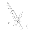
- FIG. 1 is a perspective view seen from above the indwelling needle device 100 according to the first embodiment of the present invention, in which the inner unit is in the initial position.
- an orthogonal coordinate system is set in which the longitudinal direction of the indwelling needle device 100 is the Z axis, the horizontal axis orthogonal to the Z axis, and the vertical axis are the X axis and Y axis, respectively.
- the Y-axis arrow side that is, the upper side in FIG. 1) is called “upper side”, and the opposite side is called “lower side”.
- “horizontal direction” and “vertical direction” do not mean the orientation of the indwelling needle device 100 in actual use.
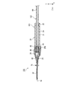
- FIG. 2 is a cross-sectional view of the indwelling needle device 100 taken along the vertical plane (YZ plane) including the line 2-2 in FIG.
- the indwelling needle device 100 includes a shield 20.
- the shield 20 includes a shield cylinder 21 and an outer hub 25 fixed to one end (front end) of the shield cylinder 21.
- the shield cylinder 21 has a substantially cylindrical shape with a constant inner diameter.
- a locking protrusion 22 that is continuous in the circumferential direction is formed on the inner peripheral surface of the shield tube 21 in the vicinity of the end (rear end) opposite to the outer hub 25.
- the outer hub 25 has a substantially funnel shape, and a soft outer needle 30 is fixed to an end (front end) opposite to the shield tube 21.
- the outer needle 30 has a substantially cylindrical shape.
- the material of the shield tube 21 and the outer hub 25 is not particularly limited, but a hard material that does not substantially deform is preferable.
- the shield cylinder 21 and the outer hub 25 be transparent or translucent because the liquid (chemical liquid or blood) in the inner cavity 24 of the shield 20 or the inner hub 40 can be seen through.
- the material of the outer needle 30 is not particularly limited, but a soft material is preferable.
- a fluorine resin such as polypropylene, polyurethane elastomer, polytetrafluoroethylene, or the like can be used.
- the outer needle 30 is transparent or translucent because the liquid (chemical liquid or blood) in the lumen and the inner needle 50 can be seen through.
- the outer hub 25 and the outer needle 30 may be integrally formed using the soft material described above.
- Reference numerals 29a and 29b are wings extending substantially parallel to the X axis.
- the wings 29 a and 29 b are provided on a substantially cylindrical fixing member 28.
- the material of the blades 29a and 29b is not particularly limited, but a soft material is preferable.
- polypropylene, vinyl chloride, polyethylene, olefin-based or polystyrene-based thermoplastic elastomers, and the like can be used.
- the wings 29a and 29b may be formed integrally with the shield 20.
- An inner hub 40 is inserted into the inner cavity 24 of the shield 20 so as to be movable in the longitudinal direction of the shield 20 (that is, the Z-axis direction).
- a metal hard inner needle 50 is fixed to the front end of the inner hub 40.
- the inner needle 50 has a substantially cylindrical shape, and the tip is processed sharply.
- One end of a flexible tube 60 is connected to the rear end of the inner hub 40.
- the other end of the tube 60 is connected to an infusion circuit for performing infusion, for example.
- An O-ring 49 is attached to the outer peripheral surface of the inner hub 40.
- the O-ring 49 is in close contact with the inner peripheral surface of the shield cylinder 21, and in the inner cavity 24 of the shield 20, the drug solution or blood on the outer needle 30 side of the O-ring 49 leaks to the tube 60 side of the O-ring 49. prevent.
- the material of the inner hub 40 is not particularly limited, but is preferably a hard material.
- polycarbonate, polypropylene, polyethylene, or the like can be used.
- the material of the tube 60 is not particularly limited, but is preferably a soft material.
- a resin material such as vinyl chloride can be used.
- the material of the O-ring 49 is not particularly limited, but is preferably a flexible material that can be elastically deformed.
- polyisoprene rubber, silicone rubber, thermoplastic elastomer, or the like can be used.
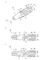
- FIG. 3A is a perspective view of the inner hub 40
- FIG. 3B is an arrow cross-sectional view of the inner hub 40 along the plane including the line 3B-3B in FIG. 3A
- FIG. 3C is along the plane including the line 3C-3C in FIG.
- FIG. 6 is a cross-sectional view of the inner hub 40 as viewed from the direction of the arrows.
- the cross section of FIG. 3B and the cross section of FIG. 3C are orthogonal to each other.
- the inner hub 40 has a front portion 41 having a conical outer surface at one end (front end) and a rear portion 42 having a cylindrical outer surface at the other end.
- a longitudinal passage 43 passes through the inner hub 40 from the front portion 41 to the rear portion 42 along the central axis 40 a of the inner hub 40.
- the inner needle 50 is inserted into the longitudinal passage 43 from the front portion 41 side and held by the inner hub 40.
- the rear portion 42 is inserted into the tube 60 and the inner hub 40 and the tube 60 are connected.
- the inner needle 50 and the tube 60 are communicated through the longitudinal passage 43 of the inner hub 40.
- annular groove 44 continuous in the circumferential direction is formed on the outer peripheral surface of the inner hub 40 between the front part 41 and the rear part 42. As shown in FIG. 2, an O-ring 49 is attached to the annular groove 44.
- a large diameter portion 45 and a small diameter portion 46 are formed in this order from the annular groove 44 side between the annular groove 44 and the front portion 41 on the outer peripheral surface of the inner hub 40.
- the small diameter portion 46 is adjacent to the front portion 41, and the outer diameter of the small diameter portion 46 is substantially the same as the maximum diameter of the front portion 41 and is smaller than the outer diameter of the large diameter portion 45.
- the front portion 41, the small diameter portion 46, and the large diameter portion 45 are formed with a transverse passage 47 that passes through them in the diameter direction (a direction orthogonal to the central axis 40a).
- the transverse passage 47 intersects and communicates with the longitudinal passage 43.
- the elastic piece 48 is arranged at equiangular intervals with respect to the central axis 40a of the inner hub 40.
- the elastic piece 48 extends substantially parallel to the central axis 40 a of the inner hub 40.
- a fitting groove 48 a and a tapered surface 48 b are formed on the surface opposite to the rear portion 42 of the elastic piece 48.
- the fitting groove 48 a is a recess (groove) along the circumferential direction of the inner hub 40.
- the tapered surface 48b is adjacent to the fitting groove 48a on the free end side of the elastic piece 48, and forms a part of a conical surface having a large outer diameter on the fitting groove 48a side.
- the shield 20, the outer needle 30 fixed to the shield 20, the wings 29 a and 29 b, and the fixing member 28 constitute an outer unit 101 of the indwelling needle device 100.
- the inner hub 40, the inner needle 50, and the tube 60 constitute an inner unit 102 of the indwelling needle device 100.
- the inner unit 102 is inserted into the outer unit 101 so as to be movable in the longitudinal direction of the shield 20 (that is, the front-rear direction).
- the inner hub 40 is located on the front end side of the inner cavity 24 of the shield 20, the inner needle 50 held by the inner hub 40 penetrates the outer needle 30, and the tip thereof is the tip of the outer needle 30. Protrudes from the outside.
- This position of the inner unit 102 with respect to the outer unit 101 is referred to as an “initial position” in the present invention.
- FIG. 4 is a perspective view seen from above the indwelling needle device 100 in which the inner unit 102 is in the retracted position.
- FIG. 5 is a cross-sectional view of the indwelling needle device 100 along the vertical plane (YZ plane) including the line 5-5 in FIG.
- the cross-sectional area of the flow path in the outer needle 30 increases by the cross-sectional integral of the inner needle 50, so the flow rate of the drug solution or blood increases.
- the flow path from the outer needle 30 to the tube 60 includes a first flow path that sequentially passes through the inner lumen of the inner needle 50 and the longitudinal passage 43 of the inner hub 40, the inner surface of the shield 20, and the inner needle 50. And the space between each outer surface of the inner hub 40, the transverse passage 47 of the inner hub 40, and the second flow path passing through the longitudinal passage 43 of the inner hub 40 in sequence, so that the drug solution or blood flows at a large flow rate. be able to.
- the inner unit 102 moves from the initial position shown in FIGS. 1 and 2 to the retracted position shown in FIGS. Can be moved to.
- the inner unit 102 When puncturing the patient with the indwelling needle device 100, the inner unit 102 must be held in the initial position.
- the clamp 70 (see FIG. 1) attached to the outer needle 30 is interposed via the outer needle 30 so that the inner unit 102 at the initial position does not move toward the retracted position.
- the inner needle 50 is held.
- the clamp 70 will be described.
- FIG. 6A is a front view of the clamp 70
- FIG. 6B is a side view thereof.
- the clamp 70 preferably has a substantially “U” shape and is made of a hard material that does not substantially deform. Specifically, for example, resin materials such as polypropylene, polyethylene, polyacetal, nylon, and acrylonitrile butadiene styrene copolymer can be used.
- the inner dimension W70 of the notch (slit) 71 formed in the clamp 70 is slightly smaller than the outer diameter of the outer needle 30.
- FIG. 7 is an enlarged cross-sectional view of the clamp 70 attached to the outer needle 30 and its periphery along a cross section parallel to the horizontal direction.
- the clamping surface 73 that faces the notch 71 of the clamp 70 sandwiches the outer needle 30. It is pressed toward the inner needle 50 to be elastically deformed.
- the inner needle 50 is made of a hard material, it does not substantially deform.
- the outer needle 30 is in close contact with the inner needle 50 at the position where the clamp 70 is mounted, and the frictional force between the outer needle 30 and the inner needle 50 increases.
- the outer needle 30 immediately recovers elastically, and the outer needle 30 and the inner needle 50 are separated by a predetermined gap.
- the indwelling needle device 100 is delivered to a medical institution such as a hospital in a state where the inner unit 102 is disposed at the initial position (FIGS. 1 and 2).
- the operator moves the inner needle 50 and the outer needle 30 with the inner unit 102 in the initial position and the inner needle 50 protruding from the tip of the outer needle 30.
- the patient's blood vessel is punctured (puncture operation).
- the puncturing operation can be performed by holding an arbitrary portion of the outer unit 101 with a finger.
- the inner needle 50 receives a reaction force opposite to the puncturing direction. This reaction force acts to move the inner unit 102 toward the retracted position with respect to the outer unit 101.
- the clamp 70 is attached to the outer needle 30 as described above, the frictional force between the outer needle 30 and the inner needle 50 is large, and both are substantially fixed. Therefore, the inner unit 102 does not move from the initial position with respect to the outer unit 101.
- the clamp 70 is removed from the outer needle 30 with the outer needle 30 punctured into the patient.
- the inner unit 102 is retracted (retracting operation). For example, while holding the outer unit 101 with one hand (for example, a hand different from the hand holding the outer unit 101 in the puncture operation) so that the outer unit 101 is not displaced with respect to the patient, the tube with the other hand The tube 60 may be pulled out from the outer unit 101 by gripping 60. Since the clamp 70 is removed, the inner unit 102 can be moved relative to the outer unit 101 by applying a relatively small tension to the tube 60. The inner unit 102 moves rearward together with the tube 60.
- a locking projection 22 is formed on the inner peripheral surface near the rear end of the shield tube 21.
- the inner hub 40 moves to the locking protrusion 22, and a tapered surface 48 b (see FIGS. 3A, 3B, and 3 C) formed on the outer surface of the elastic piece 48 of the inner hub 40 slides on the locking protrusion 22. .
- the elastic piece 48 is elastically deformed toward the rear portion 42 side.
- the taper surface 48b gets over the locking protrusion 22, the elastic piece 48 is elastically recovered, and the locking protrusion 22 is fitted into the fitting groove 48a.
- the inner unit 102 moves to the retracted position shown in FIGS.
- an adhesive tape is applied to the patient's skin from above the outer unit 101, and the indwelling needle device 100 is fixed to the patient. Only the outer needle 30 is indwelled while being punctured by the patient.
- the inner unit 102 is in the retracted position, the hard inner needle 50 does not exist in the flexible outer needle 30, so that even if the posture of the indwelling needle device 100 with respect to the patient changes temporarily due to movement of the patient, the outer needle 30 does not damage the patient's blood vessels or the like.
- the adhesive tape for fixing the outer unit 101 is peeled off from the patient, and the outer needle 30 is pulled out from the patient. Even if the tube 60 is pushed and pulled with respect to the outer unit 101, the fitting state between the fitting groove 48a of the inner hub 40 and the locking protrusion 22 of the shield tube 21 is not released. That is, the inner needle 50 cannot protrude again from the tip of the outer needle 30, and the inner unit 102 cannot be pulled out from the outer unit 101. Accordingly, it is possible to prevent the hard inner needle 50 from being punctured by mistake and the used indwelling needle device 100 from being reused by mistake. The used indwelling needle device 100 is discarded.
- the clamp 70 is attached to the outer needle 30 when the inner unit 102 is in the initial position.
- the clamp 70 holds the inner needle 50 via the outer needle 30. Therefore, even if the inner needle 50 receives a reaction force in the puncturing operation, the inner unit 102 does not move toward the retracted position and remains at the initial position. Therefore, in order to prevent the inner unit 902 in the initial position from moving toward the retracted position during the puncturing operation, the stopper 970 (FIG. 12) that is essential in the conventional indwelling needle device 900 (FIGS. 10 to 13). However, it is not necessary for the indwelling needle device 100 of the first embodiment.
- a frictional force is generated between the clamp 70 and the outer needle 30 by the pressing force applied by the clamp 70 to the outer needle 30, and this frictional force causes the clamp 70 to move to the outer needle 30 due to vibration during the transfer of the indwelling needle device 100. To prevent falling off. As long as the clamp 70 is attached to the outer needle 30, the clamp 70 holds the inner needle 50 via the outer needle 30. Therefore, if the indwelling needle device 100 is shipped with the inner unit 102 in the initial position and the clamp 70 attached, the inner unit 102 will not be displaced from the initial position due to vibration during subsequent transfer.
- the indwelling needle device 100 of the first embodiment can be realized only by using the clamp 70 instead of the stopper 970 in the conventional indwelling needle device 900. Therefore, the above-described effects of the present invention can be obtained without making a significant change to the conventional indwelling needle device 900.
- the clamp 70 is small and has a simple shape. Therefore, since the cost for producing the clamp 70 is relatively low, the cost of the indwelling needle device 100 can be reduced.
- the clamp 70 is attached to the outer needle 30 in order to hold the inner unit 102 in the initial position via the outer unit 101.
- the clamp 70 may interfere with the puncturing operation, such as the clamp 70 colliding with the patient's skin during the puncturing operation.
- the second embodiment eliminates this concern of the first embodiment.
- the indwelling needle device of the second embodiment will be described focusing on differences from the first embodiment.
- members corresponding to the members constituting the indwelling needle device 100 of the first embodiment are denoted by the same reference numerals, and description thereof is omitted.
- the second embodiment will be described focusing on differences from the first embodiment.
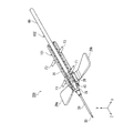
- FIG. 8 is a perspective view seen from above the indwelling needle device 200 according to the second embodiment in which the inner unit 102 is in the initial position.
- the basic configuration of the indwelling needle device 200 is the same as that of the indwelling needle device 100 (see FIG. 1) of the first embodiment except that the clamp 70 is not provided.
- the shield cylinder 21 has flexibility and can be deformed relatively easily by applying an external force.
- a soft material is preferable, For example, a polypropylene, polyethylene, a polyvinyl chloride, a polyethylene terephthalate, a polystyrene etc. can be used.
- the shield cylinder 21 Since the shield cylinder 21 is flexible, when the shield cylinder 21 is clamped by applying a pressing force in the diameter direction to the shield cylinder 21, the shield cylinder 21 is elastic so that the inner diameter of the shield cylinder 21 in the diameter direction decreases. Deform. When the pressing force is released, the shield cylinder 21 is immediately elastically restored and returns to the initial state.
- FIG. 9 is a perspective view of the indwelling needle device 200 with the shield tube 21 and the outer hub 25 cut away so that the inner unit 102 in the initial position can be seen.
- the shield tube 21 is elastically moved at the position where the pressing force F1 is applied.
- the inner surface of the shield cylinder 21 comes into contact with the inner hub 40. Since the inner hub 40 is made of a hard material, it does not substantially deform. Therefore, the inner hub 40 can be held via the shield cylinder 21 by applying the pressing force F ⁇ b> 1 to sandwich the shield cylinder 21.
- the shield tube 21 is located at the position where the pressing force F2 is applied. It is elastically deformed and the inner surface of the shield cylinder 21 comes into contact with the tube 60.
- the tube 60 is made of a soft material and can be easily deformed. However, the elastically deformed tube 60 can be held via the shield cylinder 21 by applying a large pressing force F2.
- the inner unit 102 (for example, the inner hub 40, the tube 60) located at the initial position via the shield cylinder 21 is used. Etc.) can be held.
- the method of using the indwelling needle device of the second embodiment is substantially the same as that of the first embodiment.
- the shield cylinder 21 is sandwiched and the inner unit 50 is interposed via the shield cylinder 21. 102 is held (see FIG. 9).
- the inner needle 50 and the outer needle 30 are punctured into the blood vessel of the patient.
- the inner needle 50 receives a reaction force in a direction to move the inner unit 102 toward the retracted position with respect to the outer unit 101.
- the inner unit 102 does not move from the initial position with respect to the outer unit 101.
- the holding of the inner unit 102 via the shield cylinder 21 is released by loosening the pressing force applied to the shield cylinder 21 or the like.
- the inner unit 102 is retracted by pulling the tube 60.
- the tube 60 is held with the other hand.
- the tube 60 may be pulled out from the outer unit 101 by gripping.
- care is taken that the inner unit 102 is not substantially held via the shield tube 21 by holding the outer unit 101.
- the inner unit 102 can be moved relative to the outer unit 101.
- the tube 60 is pulled to move the inner unit 102 to the retracted position (see FIGS. 4 and 5).
- the indwelling needle device 200 can hold the inner unit 102 in the initial position via the shield cylinder 21 because the shield cylinder 21 has flexibility. Therefore, similarly to the first embodiment, in the puncturing operation, even if the inner needle 50 receives a reaction force, the inner unit 102 can be held at the initial position so that the inner unit 102 does not move toward the retracted position. Therefore, the stopper 970 (FIG. 12), which is essential in the conventional indwelling needle device 900 (FIGS. 10 to 13), is unnecessary in the indwelling needle device 200 of the second embodiment.
- the stopper 970 since the stopper 970 is not used, the number of parts constituting the indwelling needle device 100 is reduced, and the cost of the indwelling needle device 100 can be reduced.
- the fixing member 28 attached to the shield tube 21 also has flexibility. Thereby, even when the outer unit 101 is clamped by the fixing member 28, the inner unit 102 at the initial position can be held, so that the selection range of the position where the outer unit 101 should be held during puncturing work is expanded. .
- the entire shield cylinder 21 has flexibility.
- the present invention is not limited to this, and only a part of the shield cylinder 21 may have flexibility.
- the inner unit 102 in the initial position can be held through the flexible portion by applying a pressing force to the flexible portion to elastically deform the portion. The same effect as above can be obtained.
- the shield cylinder 21 has flexibility, but instead of the shield cylinder 21 or in addition to the shield cylinder 21, all or part of the outer hub 25 has flexibility. It may be.
- the inner unit 102 (for example, the inner hub 40) in the initial position can be held via the outer hub 25 by applying a pressing force to the outer hub 25 to elastically deform the outer hub 25.
- the shield tube 21 has a flexible portion.
- the shield 20 is composed of the shield cylinder 21 and the outer hub 25 which are separate parts.
- the shield cylinder 21 and the outer hub 25 may be composed of a single component. .
- a part or all of the shield 20 which is the one component may be flexible.
- the inner unit 102 for example, the inner hub 40, the tube, etc.
- the shield 20 may be configured by one component in which the shield cylinder 21, the outer hub 25, and the wings 29a and 29b (including the fixing member 28) are integrated.
- the shield 20 as the one component has flexibility.
- the inner unit 102 for example, the inner hub 40, the tube, etc.
- the same effect as described above can be obtained.
- the shield 20 includes a part made of a material having flexibility as a whole, and can hold the inner unit 102 in the initial position via the part.
- the operator holds the inner unit 102 by gripping the flexible portion of the shield 20 with a finger, but the indwelling needle device 200 is attached to the flexible portion of the shield 20.
- a substantially “U” -shaped clamp similar to the clamp 70 of the first embodiment, which is detachably mounted, may be provided.
- the clamp is attached to the shield 20 during the puncturing operation and holds the inner unit 102 in the initial position via the shield 20. Then, the clamp is removed from the shield 20 immediately before shifting to the backward operation.
- the inner unit 102 in the initial position can be held by the clamp instead of the operator's finger, so that the operator holds the indwelling needle device 200 at an arbitrary position during the puncturing operation. can do. Also, if the indwelling needle device is shipped with the inner unit 102 in the initial position and the clamp 20 attached to the shield 20, it is possible to prevent the inner unit 102 from being displaced from the initial position due to vibration during subsequent transfer. it can. Compared with the clamp 70 attached to the outer needle 30 of the first embodiment, the clamp attached to the shield 20 is less likely to interfere with the puncture operation such as colliding with the patient's skin during the puncture operation.
- the shape of the clamp attached to the clamp 70 shown in Embodiment 1 or the shield 20 described in Embodiment 2 is not limited to the above example. As long as it can be detachably attached to the outer unit 101 and the inner unit 102 at the initial position can be sandwiched via the outer unit 101, it can have any shape.
- the configurations of the outer unit 101 and the inner unit 102 can be arbitrarily changed within the scope of the present invention.
- a large plane portion may be formed on the portion, or slipping may be prevented.
- An uneven shape may be formed.
- the fitting structure between the hub 40 and the shield 20 in the retracted position may have a configuration other than the above.
- the fitting structure may be omitted.
- the outer unit 101 shown in the first and second embodiments includes the shield cylinder 21, the outer hub 25, and the outer needle 30 which are separate parts, but the shield cylinder 21 and the outer hub 25 are integrated.
- the outer hub 25 and the outer needle 30 may be integrated into one part, and the shield tube 21, the outer hub 25, and the outer needle 30 may be integrated into one part. It may be configured.
- the wings 29a and 29b and the fixing member 28 that are attached to the outer unit 101 may be omitted.
- the indwelling needle device of the present invention is used for hemodialysis.
- the use of the indwelling needle device of the present invention is not limited to this, and is used for any application in which an indwelling needle device such as infusion or blood transfusion is used. can do.
- the field of application of the present invention is not particularly limited, and can be widely used as an indwelling needle device for performing treatments such as infusion, blood transfusion, and extracorporeal blood circulation. Especially, it can utilize preferably as an indwelling needle apparatus for hemodialysis.
Landscapes
- Health & Medical Sciences (AREA)
- Life Sciences & Earth Sciences (AREA)
- Biophysics (AREA)
- Pulmonology (AREA)
- Engineering & Computer Science (AREA)
- Anesthesiology (AREA)
- Biomedical Technology (AREA)
- Heart & Thoracic Surgery (AREA)
- Hematology (AREA)
- Animal Behavior & Ethology (AREA)
- General Health & Medical Sciences (AREA)
- Public Health (AREA)
- Veterinary Medicine (AREA)
- Infusion, Injection, And Reservoir Apparatuses (AREA)
Abstract
外ユニット(101)は、内腔(24)を有するシールド(20)とシールドの前端に固定された軟質の外針(30)とを備える。内ユニット(102)は、シールドの内腔内に配置された内ハブ(40)と、内ハブの前端に固定された硬質の内針(50)と、内ハブの後端に接続されたチューブ(60)とを備える。内針が外針を貫通して外針の先端から突出する初期位置から、内針がシールドの内腔内に収納される後退位置へ、内ユニットが外ユニットに対して変位する。内ユニットを初期位置に配置して穿刺したときに内針が受ける反力によって内ユニットが後退位置に向かって移動しないように、外ユニットに外力を加えて外ユニットを変形させることにより外ユニットを介して初期位置にある内ユニットを保持することができるように構成されている。
Description
本発明は、軟質の外針と硬質の内針とを備え、外針の先端から内針の先端を突出させた状態で患者に穿刺し、その後、内針を外針から後退させることができるように構成された留置針装置に関する。
留置針装置は、輸液、輸血、体外血液循環などの処置に広く使用される。このような処置において、金属針を血管内に留置すると血管が傷付けられる可能性がある。そこで、軟質の外針と硬質の内針とを備えた留置針装置が知られている。外針の先端から内針の先端を突出させた状態で外針及び内針を患者の血管に穿刺し、その後、内針を外針から後退させ、外針のみを患者に留置する。留置された軟質の外針は患者の血管を傷付ける可能性は低い。
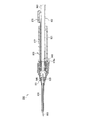
図10は、このような従来の留置針装置900(例えば特許文献1参照)の一例の上方から見た斜視図、図11は、図10の11-11線を含む垂直面に沿った従来の留置針装置900の矢視断面図である。説明の便宜のため、患者に穿刺する側(図10、図11の紙面の左側)を「前側」、これと反対側を「後ろ側」と呼ぶ。
留置針装置900は、略円筒形状を有するシールド筒921と、その一端(前端)に固定された外ハブ925とを含むシールド920を備える。外ハブ925の前端に軟質の外針930が固定されている。シールド筒921の外ハブ925側端近傍の外周面に一対の翼929a,929bが設けられている。翼929a,929bは柔軟性を有しており、上下に揺動可能である。
シールド920の内腔内には内ハブ940が挿入されている。内ハブ940の前端には金属製の硬質の内針950が固定され、内ハブ940の後端には柔軟なチューブ960の一端が接続されている。内針950とチューブ960とは、内ハブ940を前後方向に貫通する縦貫路943を介して連通している。
シールド筒921、外ハブ925、外針930、及び翼929a,929bは、留置針装置900の外ユニット901を構成する。一方、内ハブ940、内針950、及びチューブ960は、留置針装置900の内ユニット902を構成する。内ユニット902は、外ユニット901に対して、シールド920の長手方向(即ち、前後方向)に移動可能に挿入されている。
図10、図11では、内ハブ940はシールド920の内腔の前端側に位置し、内ハブ940に保持された内針950は外針930を貫通し、内針950の先端は外針930の先端から外部に突出している。外ユニット901に対する内ユニット902のこの位置を「初期位置」と呼ぶ。
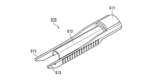
内ユニット902を初期位置に保持するために、ストッパー970が用いられる。図12はストッパー970の斜視図である。略半円筒形状の基部971から、略半円筒形状の挿入部972及び一対の固定部973が延びている。挿入部972は一対の固定部973の間に配置され、これらは互いに平行である。
図11に示されているように、シールド筒921の後端から、ストッパー970の挿入部972を挿入する。挿入部972の先端を内ハブ940の後端に衝突させて内ハブ940を前側に押し込むことにより、内ユニット902を初期位置に配置することができる。
留置針装置900は、以下のように使用される。
最初に、内ユニット902を初期位置に保持したまま、内針950及び外針930を患者の血管に穿刺する(穿刺作業)。穿刺する際に内針950が患者から受ける反力によって、内針950が外針930内に収納されてしまうのを防止する必要がある。このため、穿刺作業は、ストッパー970を保持して行う必要がある。これにより、ストッパー970及び内ユニット902は外ユニット901に対して変位せず、内ユニット902は初期位置に維持される。
内針950及び外針930を患者の血管に穿刺した後、シールド920からストッパー970を抜き去り、続いてシールド920からチューブ960を引き出す(後退作業)。チューブ960を引き出しながら同時にストッパー970をシールド920から抜き去ってもよい。チューブ960を引き出すことにより内ユニット902が外ユニット901に対して後方に移動し、図13に示すように、内針950がシールド920内に収納される。図13に示した外ユニット901に対する内ユニット902の位置を「後退位置」と呼ぶ。この状態で粘着テープ等を用いて留置針装置900を患者に固定する。留置針装置900は、軟質の外針930のみが患者に穿刺された状態で留置される。
従来の留置針装置900では、ストッパー970は、内針950及び外針930を患者に穿刺する穿刺作業において、内ユニット902を初期位置に維持するためにのみ用いられる。ストッパー970は、その後の内ユニット902を後退位置に向かって移動させる後退作業に先立って又は後退作業とともにシールド920から抜き去られる。
ところが、ストッパー970のみをシールド920から抜き去ったことにより、内ユニット902を後退位置に移動させたと勘違いし、チューブ960を引っ張るのを忘れてしまうという誤操作をする危険がある。その結果、外針930の先端から内針950が突出した状態で留置針装置900が患者に留置されるので、硬質の内針950の先端が患者の血管を傷付けてしまう可能性がある。
また、大型で複雑な形状を有するストッパー970が必要であるので、留置針装置900のコストが増大する。
本発明は、上記の従来の留置針装置の問題を解決し、穿刺作業においてストッパーを用いることなく内ユニットを初期位置に維持することができ、その結果、ストッパーが省略された留置針装置を提供することを目的とする。
本発明の留置針装置は、内腔を有するシールド、及び、前記シールドの前端に固定された軟質の外針を含む外ユニットと、前記シールドの前記内腔内に配置された内ハブ、前記内ハブの前端に固定された硬質の内針、及び、前記内ハブの後端に接続されたチューブを含む内ユニットとを備える。前記内針が前記外針を貫通して前記外針の先端から突出する初期位置から、前記内針が前記シールドの前記内腔内に収納される後退位置へ、前記内ユニットが前記外ユニットに対して変位する。前記外ユニットに外力を加えて前記外ユニットを変形させることにより前記外ユニットを介して前記初期位置にある前記内ユニットを保持することができるように本発明の留置針装置は構成されている。
本発明の留置針装置では、外ユニットに外力を加えて外ユニットを変形させることにより外ユニットを介して初期位置にある内ユニットを保持することができる。従って、内ユニットを初期位置に配置して穿刺する穿刺作業において内針が反力を受けても、ストッパーを用いることなく内ユニットを初期位置に維持することができる。その結果、従来の留置針装置において必要であったストッパーを省略することができる。
本発明の留置針装置は、内腔を有するシールド、及び、前記シールドの前端に固定された軟質の外針を含む外ユニットと、前記シールドの前記内腔内に配置された内ハブ、前記内ハブの前端に固定された硬質の内針、及び、前記内ハブの後端に接続されたチューブを含む内ユニットとを備える。前記内針が前記外針を貫通して前記外針の先端から突出する初期位置から、前記内針が前記シールドの前記内腔内に収納される後退位置へ、前記内ユニットが前記外ユニットに対して変位する。前記外ユニットに外力を加えて前記外ユニットを変形させることにより前記外ユニットを介して前記初期位置にある前記内ユニットを保持することができるように本発明の留置針装置は構成されている。
上記の本発明の留置針装置が、前記外針を挟持するように前記外針に取り外し可能に装着されたクランプを更に備えることが好ましい。この場合、前記クランプは、前記外針を介して前記初期位置にある前記内ユニットの前記内針を保持することが好ましい。これにより、外針にクランプを装着するだけで、初期位置にある内ユニットの後退位置への移動を防止することができる。従って、従来の留置針装置900(図10参照)においてストッパーの代わりにクランプを用いるという簡単な変更を加えるだけで、本発明の留置針装置を実現できる。ストッパーに比べて、クランプを小型で簡素な形状にすることが可能であるので、留置針装置の低コスト化が可能である。内ユニットを初期位置にし且つ外針にクランプを装着した状態で留置針装置を出荷すれば、その後の移送中の振動などにより内ユニットが初期位置から位置ずれするのを防ぐことができる。
上記の本発明の留置針装置において、前記シールドの少なくとも一部が可撓性を有することが好ましい。この場合、前記シールドの前記可撓性を有する部分を介して前記初期位置にある前記内ユニットを保持することができることが好ましい。かかる好ましい構成によれば、作業者が指で、あるいは、クランプを装着することにより、シールドの可撓性を有する部分を変形させることにより、初期位置にある内ユニットを保持することができる。外針にクランプを装着する必要がないので、外針に装着されたクランプが穿刺作業の邪魔になるという問題は生じない。作業者が指で、シールドの可撓性を有する部分を挟持して内ユニットを保持すれば、ストッパーに加えてクランプも不要になるので、留置針装置を構成する部品点数が少なくなり、留置針装置の低コスト化が可能である。
上記において、前記シールドの前記可撓性を有する部分を介して前記内ユニットの前記内ハブを保持することができるように構成されていてもよい。あるいは、前記シールドの前記可撓性を有する部分を介して前記内ユニットの前記チューブを保持することができるように構成されていてもよい。内ハブは一般に硬質材料からなるので、シールドを介して内ハブを保持することは、チューブを保持する場合に比べて、初期位置にある内ユニットを確実に保持するのに有利である。
前記シールドは、その全体が可撓性を有する材料で構成された部品を含むことが好ましい。この場合、前記部品を介して前記初期位置にある前記内ユニットを保持することができることが好ましい。部品全体を可撓性を有する材料で構成することは、部品の一部のみを可撓性を有する材料で構成した場合に比べて、当該部品の作成が容易になるので、留置針装置の低コスト化に有利である。また、当該部品の任意の箇所に外力を加えて内ユニットを保持することができる。
前記シールドは、前記外針を保持する外ハブと、前記外ハブが一端に固定された筒状のシールド筒とを備えることが好ましい。この場合、前記シールドの前記可撓性を有する部分が前記シールド筒に設けられていてもよい。あるいは、前記シールドの前記可撓性を有する部分が前記外ハブに設けられていてもよい。
上記の本発明の留置針装置が、前記シールドを挟持するように前記シールドの前記可撓性を有する部分に取り外し可能に装着されたクランプを更に備えることが好ましい。この場合、前記クランプは、前記シールドの前記可撓性を有する部分を介して前記初期位置にある前記内ユニットを保持することが好ましい。かかる好ましい構成によれば、初期位置にある内ユニットの保持を、作業者の指ではなくクランプで行うことができるので、穿刺作業時に作業者は留置針装置を任意の位置で保持することができる。また、内ユニットを初期位置にし且つシールドにクランプを装着した状態で留置針装置を出荷すれば、その後の移送中の振動などにより内ユニットが初期位置から位置ずれするのを防ぐこともできる。
以下に、本発明を好適な実施形態を示しながら詳細に説明する。但し、本発明は以下の実施形態に限定されないことはいうまでもない。以下の説明において参照する各図は、説明の便宜上、本発明の実施形態の構成部材のうち、本発明を説明するために必要な主要部材のみを簡略化して示したものである。従って、本発明は以下の各図に示されていない任意の構成部材を備え得る。また、以下の各図中の部材の寸法は、実際の構成部材の寸法および各部材の寸法比率等を忠実に表したものではない。
(実施形態1)
図1は、内ユニットが初期位置にある、本発明の実施形態1にかかる留置針装置100の上方から見た斜視図である。以下の説明の便宜のため、留置針装置100の長手方向をZ軸、Z軸と直交する水平方向軸及び上下方向軸をそれぞれX軸及びY軸とする直交座標系を設定する。Y軸の矢印の側(即ち、図1の紙面の上側)を「上側」、これと反対側を「下側」と呼ぶ。但し、「水平方向」及び「上下方向」は、留置針装置100の実際の使用時の向きを意味するものではない。更に、患者に穿刺する側(Z軸の矢印の側、即ち、図1の紙面の左側)を「前側」、これと反対側を「後ろ側」と呼ぶ。図2は、図1の2-2線を含む垂直面(YZ面)に沿った留置針装置100の矢視断面図である。
図1は、内ユニットが初期位置にある、本発明の実施形態1にかかる留置針装置100の上方から見た斜視図である。以下の説明の便宜のため、留置針装置100の長手方向をZ軸、Z軸と直交する水平方向軸及び上下方向軸をそれぞれX軸及びY軸とする直交座標系を設定する。Y軸の矢印の側(即ち、図1の紙面の上側)を「上側」、これと反対側を「下側」と呼ぶ。但し、「水平方向」及び「上下方向」は、留置針装置100の実際の使用時の向きを意味するものではない。更に、患者に穿刺する側(Z軸の矢印の側、即ち、図1の紙面の左側)を「前側」、これと反対側を「後ろ側」と呼ぶ。図2は、図1の2-2線を含む垂直面(YZ面)に沿った留置針装置100の矢視断面図である。
留置針装置100は、シールド20を備える。シールド20は、シールド筒21と、シールド筒21の一端(前端)に固定された外ハブ25とを有する。シールド筒21は、内径が一定の略円筒形状を有する。シールド筒21の外ハブ25とは反対側端(後端)近傍の内周面には、周方向に連続する係止突起22が形成されている。外ハブ25は略漏斗形状を有し、そのシールド筒21とは反対側端(前端)に軟質の外針30が固定されている。外針30は略円筒形状を有する。シールド筒21及び外ハブ25の材料としては、特に制限はないが、実質的に変形しない硬質材料が好ましく、例えば、ポリカーボネート、ポリプロピレン等を用いることができる。シールド筒21及び外ハブ25が透明又は透光性を有すると、シールド20の内腔24内の液体(薬液又は血液など)や内ハブ40を透視することができるので好ましい。外針30の材料としては、特に制限はないが、軟質材料が好ましく、例えば、ポリプロピレン、ポリウレタン系エラストマー、ポリテトラフルオロエチレン等のフッ素樹脂等を用いることができる。外針30が透明又は透光性を有すると、その内腔内の液体(薬液又は血液など)や内針50を透視することができるので好ましい。なお、外ハブ25及び外針30を、上記の軟質材料を用いて一体に形成してもよい。
参照符号29a,29bは、X軸と略平行に延びた翼である。翼29a,29bは、略円筒形状の固定部材28に設けられている。固定部材28をシールド筒21の外ハブ25側端近傍の外周面に外装することにより、翼29a,29bがシールド20に装着されている。翼29a,29bの材料としては、特に制限はないが、軟質材料が好ましく、例えば、ポリプロピレン、塩化ビニル、ポリエチレン、オレフィン系又はポリスチレン系の熱可塑性エラストマー等を用いることができる。なお、翼29a,29bは、シールド20に一体に成形されていてもよい。
シールド20の内腔24内には内ハブ40が、シールド20の長手方向(即ち、Z軸方向)に移動可能に挿入されている。内ハブ40の前端には金属製の硬質の内針50が固定されている。内針50は略円筒形状を有し、その先端は鋭利に加工されている。内ハブ40の後端には柔軟なチューブ60の一端が接続されている。チューブ60の他端は、例えば輸液を行うための点滴回路に接続されている。内ハブ40の外周面にOリング49が装着されている。Oリング49はシールド筒21の内周面に密着し、シールド20の内腔24において、Oリング49よりも外針30側の薬液又は血液がOリング49よりもチューブ60側に漏洩するのを防ぐ。内ハブ40の材料としては、特に制限はないが、硬質材料が好ましく、例えば、ポリカーボネート、ポリプロピレン、ポリエチレン等を用いることができる。チューブ60の材料としては、特に制限はないが、軟質材料が好ましく、例えば、塩化ビニル等の樹脂材料を用いることができる。Oリング49の材料としては、特に制限はないが、柔軟性を有し弾性的変形可能な材料が好ましく、例えば、ポリイソプレンゴム、シリコーンゴム、熱可塑性エラストマー等を用いることができる。
図3Aは内ハブ40の斜視図、図3Bは図3Aの3B-3B線を含む面に沿った内ハブ40の矢視断面図、図3Cは図3Aの3C-3C線を含む面に沿った内ハブ40の矢視断面図である。図3Bの断面と図3Cの断面とは互いに直交する。内ハブ40は、一端(前端)に、円錐面状の外面を有する前部41を有し、他端に円筒面状の外面を有する後部42を有する。縦貫路43が、内ハブ40の中心軸40aに沿って前部41から後部42まで内ハブ40を縦貫している。図2に示されているように、内針50は、前部41側から縦貫路43内に挿入されて、内ハブ40に保持される。後部42がチューブ60内に挿入されて、内ハブ40とチューブ60とが接続される。かくして、内針50とチューブ60とは、内ハブ40の縦貫路43を通じて連通される。
前部41と後部42との間の、内ハブ40の外周面に、周方向に連続する環状溝44が形成されている。図2に示されているように、環状溝44にOリング49が装着される。
内ハブ40の外周面に、環状溝44と前部41との間に、環状溝44側から径大部45及び径小部46がこの順に形成されている。径小部46は前部41に隣接し、径小部46の外径は、前部41の最大径とほぼ同じであり、且つ、径大部45の外径よりも小さい。前部41、径小部46、及び径大部45には、これらを直径方向(中心軸40aに直交する方向)に横貫する横貫路47が形成されている。横貫路47は、縦貫路43と交差し且つ連通している。
後部42の周囲に、片持ち支持された4つの弾性片48が、内ハブ40の中心軸40aに対して等角度間隔で配置されている。弾性片48は、内ハブ40の中心軸40aに対して略平行に延びている。弾性片48の後部42とは反対側の面には、嵌合溝48aとテーパ面48bとが形成されている。嵌合溝48aは、内ハブ40の周方向に沿った凹部(溝)である。テーパ面48bは、嵌合溝48aに対して弾性片48の自由端側に隣接し、嵌合溝48a側で外径が大きな円錐面の一部をなす。
シールド20と、シールド20に固定された外針30、翼29a,29b、及び固定部材28は留置針装置100の外ユニット101を構成する。一方、内ハブ40、内針50、及びチューブ60は、留置針装置100の内ユニット102を構成する。内ユニット102は、外ユニット101に対して、シールド20の長手方向(即ち、前後方向)に移動可能に挿入されている。
図1、図2では、内ハブ40はシールド20の内腔24の前端側に位置し、内ハブ40に保持された内針50は外針30を貫通し、その先端は外針30の先端から外部に突出している。外ユニット101に対する内ユニット102のこの位置を本発明では「初期位置」と呼ぶ。
図4は、内ユニット102が後退位置にある留置針装置100の上方から見た斜視図である。図5は、図4の5-5線を含む垂直面(YZ面)に沿った留置針装置100の矢視断面図である。
図5に示されているように、内ユニット102が「後退位置」にあるとき、内ハブ40の嵌合溝48a(図3A、図3B、図3Cを参照)とシールド筒21の係止突起22とが嵌合している。また、内ハブ40に保持された内針50は外針30から抜き去られ、シールド20の内腔24内に収納されている。
初期位置(図1、図2参照)に比べると、後退位置では、外針30内の流路の断面積は内針50の断面積分だけ増大するので、薬液又は血液の流量が増大する。また、後退位置では、外針30からチューブ60に至る流路としては、内針50の内腔及び内ハブ40の縦貫路43を順に通る第1流路と、シールド20の内面と内針50及び内ハブ40の各外面との間の空間、内ハブ40の横貫路47、及び内ハブ40の縦貫路43を順に通る第2流路の2つがあるので、大きな流量で薬液又は血液を流すことができる。
以上のように、本実施形態1の留置針装置100では、内ユニット102は、図1及び図2に示す初期位置から図4及び図5に示す後退位置に、外ユニット101に対して前後方向に移動することができる。
留置針装置100を患者に穿刺する際には、内ユニット102は初期位置に保持されなければならない。本実施形態1の留置針装置100では、初期位置にある内ユニット102が後退位置に向かって移動しないように、外針30に装着されたクランプ70(図1参照)が、外針30を介して内針50を保持している。
クランプ70について説明する。
図6Aはクランプ70の正面図、図6Bはその側面図である。クランプ70は、略「U」字形状を有し、実質的に変形しない硬質材料からなることが好ましい。具体的には、例えば、ポリプロピレン、ポリエチレン、ポリアセタール、ナイロン、アクリロニトリルブタジエンスチレン共重合体等の樹脂材料を用いることができる。クランプ70に形成された切り欠き(スリット)71の内寸法W70は、外針30の外径より僅かに小さい。
クランプ70は、図1に示されるように、内ユニット102が初期位置にあるときにその切り欠き71(図6A参照)内に外針30が嵌入するように、外針30に装着される。図7は、外針30に装着されたクランプ70及びその周辺の、水平方向に平行な断面に沿った拡大断面図である。上述したように、クランプ70の切り欠き71の内寸法W70が外針30の外径より小さいので、クランプ70の切り欠き71を挟んで対向する挟持面73(図6A参照)が外針30を内針50に向かって押圧し弾性的に変形させている。一方、内針50は硬質材料からなるので、実質的に変形しない。従って、クランプ70が装着された位置で、外針30は内針50に密着し、外針30と内針50との間の摩擦力が増大する。外針30からクランプ70を取り除くと、外針30は直ちに弾性回復し、外針30と内針50とは所定の隙間で離間する。
以上のように構成された本実施形態1の留置針装置100の使用方法及び作用を説明する。
本実施形態1の留置針装置100は、内ユニット102が初期位置に配置された状態(図1、図2)で病院などの医療機関に納入される。
医療機関では、作業者は、図1及び図2に示すように、内ユニット102が初期位置にあり且つ内針50が外針30の先端から突出した状態で、内針50及び外針30を患者の血管に穿刺する(穿刺作業)。穿刺作業は、外ユニット101の任意の箇所を指で把持して行うことができる。このとき、内針50は、穿刺する向きとは逆向きの反力を受ける。この反力は、内ユニット102を外ユニット101に対して後退位置の側に移動させるように作用する。ところが、上述したように、外針30にクランプ70が装着されているので、外針30と内針50との間の摩擦力は大きく、両者は実質的に固着されている。従って、内ユニット102は、外ユニット101に対して初期位置から移動することはない。
次に、外針30を患者に穿刺した状態で、クランプ70を外針30から取り除く。続いて、内ユニット102を後退させる(後退作業)。例えば、外ユニット101が患者に対して変位しないように一方の手(例えば穿刺作業で外ユニット101を把持していたのとは異なる手)で外ユニット101を保持しながら、他方の手でチューブ60を把持して外ユニット101からチューブ60を引き出せばよい。クランプ70が取り除かれているので、比較的小さな張力をチューブ60に印加することにより、外ユニット101に対して内ユニット102を移動させることができる。内ユニット102はチューブ60とともに後方に移動する。
シールド筒21の後端近傍の内周面には係止突起22が形成されている。内ハブ40が係止突起22まで移動し、内ハブ40の弾性片48の外面に形成されたテーパ面48b(図3A、図3B、図3Cを参照)が係止突起22上を摺動する。このとき弾性片48は後部42側に弾性変形する。次いで、テーパ面48bが係止突起22を乗り越えると、弾性片48が弾性回復し、嵌合溝48aに係止突起22が嵌入する。かくして、内ユニット102は図4及び図5に示した後退位置に移動する。
この状態で外ユニット101の上から粘着テープを患者の皮膚に貼り付け、留置針装置100を患者に固定する。外針30のみが患者に穿刺された状態で留置される。内ユニット102が後退位置にあるとき、柔軟な外針30内に硬質の内針50が存在しないので、患者が動くなどにより、患者に対する留置針装置100の姿勢が仮に変化しても、外針30が患者の血管等を傷付けることはない。
必要な処置が終了すると、外ユニット101を固定する粘着テープを患者から剥がし、外針30を患者から引き抜く。外ユニット101に対してチューブ60を押し引きしても、内ハブ40の嵌合溝48aとシールド筒21の係止突起22との嵌合状態は解除されない。即ち、内針50を外針30の先端から再度突出させたり、内ユニット102を外ユニット101から引き出したりすることはできない。従って、硬質の内針50を誤って穿刺したり、使用済みの留置針装置100を誤って再使用したりするのを防止している。使用済みの留置針装置100は廃棄される。
以上のように本実施形態1の留置針装置100は、内ユニット102が初期位置にあるとき、外針30にクランプ70が装着される。クランプ70は、外針30を介して内針50を保持する。従って、穿刺作業において内針50が反力を受けても、内ユニット102は、後退位置に向かって移動することはなく初期位置のままである。よって、初期位置にある内ユニット902が穿刺作業時に後退位置に向かって移動するのを防止するために従来の留置針装置900(図10~図13)では必須であったストッパー970(図12)が、本実施形態1の留置針装置100では不要である。
上述したように、従来の留置針装置900では、ストッパー970をシールド920から抜き去ったことにより、内ユニット902が後退位置に移動したと勘違いするという誤操作をする危険があった。これに対して、本実施形態1では、ストッパーは存在しない。シールド20から引き出すべきものはチューブ60以外に存在しない。従って、従来の留置針装置900で起こりうる上記の勘違いは本実施形態1の留置針装置100では起こらない。よって、誤操作をする危険が低減される。
外針30からクランプ70を取り除くのを忘れてチューブ60を引っ張っても、内ユニット102を移動させるのは困難である。従って、作業者は、クランプ70を外針30から取り除くのを忘れたことに容易に気づく。この点でも、誤操作をする可能性は低い。
クランプ70が外針30に印加する押力によってクランプ70と外針30との間に摩擦力が発生し、この摩擦力が、留置針装置100を移送中に振動などによりクランプ70が外針30から脱落するのを防止する。クランプ70は、外針30に装着されている限り、外針30を介して内針50を保持する。従って、内ユニット102を初期位置にし且つクランプ70を装着した状態で留置針装置100を出荷すれば、その後の移送中の振動などにより内ユニット102が初期位置から位置ずれすることもない。
本実施形態1の留置針装置100は、従来の留置針装置900においてストッパー970の代わりにクランプ70を用いるだけで実現できる。従って、従来の留置針装置900に大幅な変更を加えることなく本発明の上記の効果を得ることができる。ストッパー970に比べて、クランプ70は小型であり、簡素な形状を有している。従って、クランプ70を作成するためのコストは相対的に低いので、留置針装置100の低コスト化が可能である。
(実施形態2)
上述した実施形態1では、外ユニット101を介して初期位置にある内ユニット102を保持するために、外針30にクランプ70を装着した。穿刺作業においてクランプ70が患者の皮膚に衝突するなど、クランプ70が穿刺作業の邪魔になることが懸念される。本実施形態2は、実施形態1のこの懸念を解消する。以下、実施形態1との相違点を中心に、本実施形態2の留置針装置を説明する。以下の説明で参照する図面において、実施形態1の留置針装置100を構成する部材に対応する部材には同一の符号を付して、それらの説明を省略する。以下、実施形態1との相違点を中心に本実施形態2を説明する。
上述した実施形態1では、外ユニット101を介して初期位置にある内ユニット102を保持するために、外針30にクランプ70を装着した。穿刺作業においてクランプ70が患者の皮膚に衝突するなど、クランプ70が穿刺作業の邪魔になることが懸念される。本実施形態2は、実施形態1のこの懸念を解消する。以下、実施形態1との相違点を中心に、本実施形態2の留置針装置を説明する。以下の説明で参照する図面において、実施形態1の留置針装置100を構成する部材に対応する部材には同一の符号を付して、それらの説明を省略する。以下、実施形態1との相違点を中心に本実施形態2を説明する。
図8は、内ユニット102が初期位置にある、本実施形態2にかかる留置針装置200の上方から見た斜視図である。留置針装置200の基本的構成は、クランプ70を備えていない点を除いて実施形態1の留置針装置100(図1参照)と同じである。但し、本実施形態2では、シールド筒21が可撓性を有しており、外力を加えることにより比較的容易に変形させることができる。シールド筒21の材料としては、特に制限はないが、軟質材料が好ましく、例えば、ポリプロピレン、ポリエチレン、ポリ塩化ビニル、ポリエチレンテレフタレート、ポリスチレン等を用いることができる。
シールド筒21が可撓性を有するため、シールド筒21に直径方向の押力を印加してシールド筒21を挟持すると、シールド筒21の当該直径方向の内径が減少するようにシールド筒21は弾性変形する。押力を解除すると、シールド筒21は直ちに弾性回復して初期状態に戻る。
図9は、初期位置にある内ユニット102が見えるようにシールド筒21及び外ハブ25が切り欠かれた留置針装置200の斜視図である。
例えば、固定部材28の近傍の位置にシールド筒21の直径方向に沿った押力F1を印加してシールド筒21を挟持すると、押力F1が印加された位置にてシールド筒21は弾性的に変形し、シールド筒21の内面が内ハブ40に当接する。内ハブ40は硬質材料からなるので、実質的に変形しない。従って、押力F1を印加してシールド筒21を挟持することにより、シールド筒21を介して内ハブ40を保持することができる。
あるいは、シールド筒21の長手方向のほぼ中央位置にシールド筒21の直径方向に沿った押力F2を印加してシールド筒21を挟持すると、押力F2が印加された位置にてシールド筒21は弾性的に変形し、シールド筒21の内面がチューブ60に当接する。チューブ60は軟質材料からなり、容易に変形することができる。但し、大きな押力F2を印加することにより、シールド筒21を介して弾性的に変形したチューブ60を保持することができる。
このように、本実施形態2では、シールド筒21が可撓性を有するので、シールド筒21を挟持すると、シールド筒21を介して初期位置にある内ユニット102(例えば、内ハブ40,チューブ60等)を保持することができる。
本実施形態2の留置針装置の使用方法は、実施形態1と概略同じである。
穿刺作業では、内ユニット102が初期位置にあり且つ内針50が外針30の先端から突出した状態(図8を参照)で、シールド筒21を挟持して、シールド筒21を介して内ユニット102を保持する(図9を参照)。この状態で内針50及び外針30を患者の血管に穿刺する。このとき、内針50は、内ユニット102を外ユニット101に対して後退位置の側に移動させる向きの反力を受ける。ところが、内ユニット102はシールド筒21を介して作業者の指によって保持されているので、内ユニット102は、外ユニット101に対して初期位置から移動することはない。
次の後退作業では、最初に、シールド筒21に印加していた押力を緩める等によりシールド筒21を介した内ユニット102の保持を解除する。続いて、外針30を患者に穿刺した状態で、チューブ60を引っ張って内ユニット102を後退させる。例えば、外ユニット101が患者に対して変位しないように一方の手(例えば穿刺作業で外ユニット101を把持していた方の手)で外ユニット101を保持しながら、他方の手でチューブ60を把持して外ユニット101からチューブ60を引き出せばよい。このとき、外ユニット101の保持によって、シールド筒21を介して内ユニット102が実質的に保持されることがないように注意する。比較的小さな張力をチューブ60に印加することにより、外ユニット101に対して内ユニット102を移動させることができる。チューブ60を引っ張って内ユニット102を後退位置(図4、図5を参照)に移動させる。
以上のように本実施形態2の留置針装置200は、シールド筒21が可撓性を有するので、シールド筒21を介して初期位置にある内ユニット102を保持することができる。従って、実施形態1と同様に、穿刺作業において、内針50が反力を受けても、内ユニット102が後退位置に向かって移動しないように内ユニット102を初期位置に保持することができる。よって、従来の留置針装置900(図10~図13)では必須であったストッパー970(図12)が、本実施形態2の留置針装置200では不要である。
ストッパーが不要であるので、ストッパー970を備えた従来の留置針装置900で起こりうる誤操作の危険性が低減される。また、穿刺作業から後退作業に移行する際に、作業者は、通常、留置針装置200の持ち位置を変えるので、これと同時にシールド筒21を介した内ユニット102の保持も解除される。この点でも、誤操作をする可能性は低い。
また、ストッパー970を用いないので、留置針装置100を構成する部品点数が少なくなり、留置針装置100の低コスト化が可能である。
上記の例において、シールド筒21に装着された固定部材28も可撓性を有していることが好ましい。これにより、外ユニット101を固定部材28にて挟持した場合にも、初期位置にある内ユニット102を保持することができるので、穿刺作業時に外ユニット101を保持すべき位置の選択範囲が拡大する。
上記の例では、シールド筒21の全体が可撓性を有していたが、本発明はこれに限定されず、シールド筒21の一部のみが可撓性を有していてもよい。この場合、可撓性を有する部分に押力を印加して当該部分を弾性的に変形させることにより、可撓性を有する部分を介して初期位置にある内ユニット102を保持することができ、上記と同様の効果が得られる。
上記の例では、シールド筒21が可撓性を有していたが、シールド筒21に代えて、または、シールド筒21に加えて、外ハブ25の全部又は一部が可撓性を有していてもよい。この場合、外ハブ25に押力を印加して外ハブ25を弾性的に変形させることにより、外ハブ25を介して初期位置にある内ユニット102(例えば内ハブ40)を保持することができ、上記と同様の効果が得られる。但し、穿刺作業を行う際に留置針装置200を安定的に保持する観点からは、シールド筒21が可撓性を有する部分を備えていることが好ましい。
上記の例では、シールド20が、別部品であるシールド筒21と外ハブ25とで構成されていたが、シールド筒21と外ハブ25とが一体化された一部品で構成されていてもよい。この場合、当該一部品であるシールド20の一部又は全部が可撓性を有していればよい。シールド20の可撓性を有する部分に押力を印加してシールド20を弾性的に変形させることにより、可撓性を有する部分を介して初期位置にある内ユニット102(例えば内ハブ40、チューブ60等)を保持することができるので、上記と同様の効果が得られる。更に、シールド筒21、外ハブ25、及び翼29a,29b(固定部材28を含む)が一体化された一部品でシールド20が構成されていてもよい。この場合も、当該一部品であるシールド20の一部又は全部が可撓性を有していればよい。シールド20の可撓性を有する部分に押力を印加してシールド20を弾性的に変形させることにより、可撓性を有する部分を介して初期位置にある内ユニット102(例えば内ハブ40、チューブ60等)を保持することができるので、上記と同様の効果が得られる。
一般に、部品の全体を可撓性を有する材料で構成することは、部品の一部のみを可撓性を有する材料で構成する場合に比べて、当該部品の作成が容易である。また、部品の全体が可撓性を有する場合には、当該部品の任意の位置を介して初期位置にある内ユニット102を保持することができる。従って、シールド20は、その全体が可撓性を有する材料で構成された部品を備え、当該部品を介して初期位置にある内ユニット102を保持できることが好ましい。
上記の説明では、作業者が、シールド20の可撓性を有する部分を指で把持することにより、内ユニット102を保持したが、留置針装置200が、シールド20の可撓性を有する部分に取り外し可能に装着される、実施形態1のクランプ70と同様の略「U」字形状のクランプを備えていてもよい。この場合には、実施形態1のクランプ70(図6参照)と同様に、当該クランプは穿刺作業時にはシールド20に装着されてシールド20を介して初期位置にある内ユニット102を保持する。そして、クランプは、後退作業に移行する直前にシールド20から取り外される。このようなクランプを備えることにより、初期位置にある内ユニット102の保持を、作業者の指ではなくクランプで行うことができるので、穿刺作業時に作業者は留置針装置200を任意の位置で保持することができる。また、内ユニット102を初期位置にし且つシールド20にクランプを装着した状態で留置針装置を出荷すれば、その後の移送中の振動などにより内ユニット102が初期位置から位置ずれするのを防ぐこともできる。シールド20に装着したクランプは、実施形態1の外針30に装着したクランプ70に比べて、穿刺作業において患者の皮膚に衝突する等の穿刺作業の邪魔になる可能性は低い。
本実施形態2に示した、シールド20が可撓性を有する部分を有し、当該可撓性を有する部分を介して初期位置にある内ユニット102を保持することができる構成を、実施形態1に組み合わせることができる。
上記の実施形態1,2は例示に過ぎない。本発明は上記の実施形態1,2に限定されず、適宜変更することができる。
実施形態1に示したクランプ70や実施形態2で説明したシールド20に装着されるクランプの形状は、上記の例に限定されない。外ユニット101に取り外し可能に装着することができ、外ユニット101を介して初期位置にある内ユニット102を挟持することができれば、任意の形状を有することができる。
外ユニット101及び内ユニット102の構成は、本発明の範囲内において任意に変更することができる。
例えば、実施形態2において、シールド20の可撓性を有する部分を挟持して押力を印加しやすくするために、当該部分に大面積の平面部を形成してもよく、あるいは、滑りを防止するための凹凸形状を形成してもよい。
後退位置にあるハブ40とシールド20との嵌合構造は、上記以外の構成を有していてもよい。あるいは、当該嵌合構造を省略してもよい。
上記の実施形態1,2に示した外ユニット101は、互いに別部品であるシールド筒21、外ハブ25、及び外針30を備えていたが、シールド筒21と外ハブ25とを一体化して一部品で構成してもよく、外ハブ25と外針30とを一体化して一部品で構成してもよく、更にシールド筒21、外ハブ25、及び外針30を一体化して一部品で構成してもよい。外ユニット101に装着されていた翼29a,29b及び固定部材28を省略してもよい。
上記の説明では本発明の留置針装置を血液透析に用いたが、本発明の留置針装置の用途はこれに限定されず、輸液や輸血等の留置針装置が使用される任意の用途に利用することができる。
本発明の利用分野は特に制限はなく、輸液、輸血、体外血液循環などの処置を行う際の留置針装置として広範囲に利用することができる。中でも、血液透析用の留置針装置として好ましく利用することができる。
100 留置針装置
101 外ユニット
102 内ユニット
20 シールド
21 シールド筒
24 シールドの内腔
25 外ハブ
30 外針
40 内ハブ
50 内針
60 チューブ
70 クランプ
101 外ユニット
102 内ユニット
20 シールド
21 シールド筒
24 シールドの内腔
25 外ハブ
30 外針
40 内ハブ
50 内針
60 チューブ
70 クランプ
Claims (9)
- 内腔を有するシールド、及び、前記シールドの前端に固定された軟質の外針を含む外ユニットと、
前記シールドの前記内腔内に配置された内ハブ、前記内ハブの前端に固定された硬質の内針、及び、前記内ハブの後端に接続されたチューブを含む内ユニットとを備え、
前記内針が前記外針を貫通して前記外針の先端から突出する初期位置から、前記内針が前記シールドの前記内腔内に収納される後退位置へ、前記内ユニットが前記外ユニットに対して変位する留置針装置であって、
前記外ユニットに外力を加えて前記外ユニットを変形させることにより前記外ユニットを介して前記初期位置にある前記内ユニットを保持することができるように構成されたことを特徴とする留置針装置。 - 前記外針を挟持するように前記外針に取り外し可能に装着されたクランプを更に備え、
前記クランプは、前記外針を介して前記初期位置にある前記内ユニットの前記内針を保持する請求項1に記載の留置針装置。 - 前記シールドの少なくとも一部が可撓性を有し、
前記シールドの前記可撓性を有する部分を介して前記初期位置にある前記内ユニットを保持することができる請求項1に記載の留置針装置。 - 前記シールドの前記可撓性を有する部分を介して前記内ユニットの前記内ハブを保持することができる請求項3に記載の留置針装置。
- 前記シールドの前記可撓性を有する部分を介して前記内ユニットの前記チューブを保持することができる請求項3に記載の留置針装置。
- 前記シールドは、その全体が可撓性を有する材料で構成された部品を含み、前記部品を介して前記初期位置にある前記内ユニットを保持することができる請求項3~5のいずれかに記載の留置針装置。
- 前記シールドは、前記外針を保持する外ハブと、前記外ハブが一端に固定された筒状のシールド筒とを備え、
前記シールドの前記可撓性を有する部分が前記シールド筒に設けられている請求項3~5のいずれかに記載の留置針装置。 - 前記シールドは、前記外針を保持する外ハブと、前記外ハブが一端に固定された筒状のシールド筒とを備え、
前記シールドの前記可撓性を有する部分が前記外ハブに設けられている請求項3~5のいずれかに記載の留置針装置。 - 前記シールドを挟持するように前記シールドの前記可撓性を有する部分に取り外し可能に装着されたクランプを更に備え、
前記クランプは、前記シールドの前記可撓性を有する部分を介して前記初期位置にある前記内ユニットを保持する請求項3~8のいずれかに記載の留置針装置。
Applications Claiming Priority (2)
| Application Number | Priority Date | Filing Date | Title |
|---|---|---|---|
| JP2012-125046 | 2012-05-31 | ||
| JP2012125046A JP2013248158A (ja) | 2012-05-31 | 2012-05-31 | 留置針装置 |
Publications (1)
| Publication Number | Publication Date |
|---|---|
| WO2013180233A1 true WO2013180233A1 (ja) | 2013-12-05 |
Family
ID=49673420
Family Applications (1)
| Application Number | Title | Priority Date | Filing Date |
|---|---|---|---|
| PCT/JP2013/065081 Ceased WO2013180233A1 (ja) | 2012-05-31 | 2013-05-30 | 留置針装置 |
Country Status (2)
| Country | Link |
|---|---|
| JP (1) | JP2013248158A (ja) |
| WO (1) | WO2013180233A1 (ja) |
Families Citing this family (1)
| Publication number | Priority date | Publication date | Assignee | Title |
|---|---|---|---|---|
| CN105833389B (zh) * | 2016-05-20 | 2022-01-18 | 苏州林华医疗器械股份有限公司 | 耐压低阻隔离塞及静脉留置针 |
Citations (3)
| Publication number | Priority date | Publication date | Assignee | Title |
|---|---|---|---|---|
| JP2001252356A (ja) * | 2000-03-10 | 2001-09-18 | Jms Co Ltd | 翼付き注射針装置 |
| JP2006297062A (ja) * | 2005-03-24 | 2006-11-02 | Jms Co Ltd | 留置針装置 |
| JP4151311B2 (ja) * | 2002-05-24 | 2008-09-17 | ニプロ株式会社 | 留置針 |
-
2012
- 2012-05-31 JP JP2012125046A patent/JP2013248158A/ja active Pending
-
2013
- 2013-05-30 WO PCT/JP2013/065081 patent/WO2013180233A1/ja not_active Ceased
Patent Citations (3)
| Publication number | Priority date | Publication date | Assignee | Title |
|---|---|---|---|---|
| JP2001252356A (ja) * | 2000-03-10 | 2001-09-18 | Jms Co Ltd | 翼付き注射針装置 |
| JP4151311B2 (ja) * | 2002-05-24 | 2008-09-17 | ニプロ株式会社 | 留置針 |
| JP2006297062A (ja) * | 2005-03-24 | 2006-11-02 | Jms Co Ltd | 留置針装置 |
Also Published As
| Publication number | Publication date |
|---|---|
| JP2013248158A (ja) | 2013-12-12 |
Similar Documents
| Publication | Publication Date | Title |
|---|---|---|
| JP5594520B2 (ja) | 留置針装置 | |
| JP6925484B2 (ja) | カテーテル組立体 | |
| JP5790972B2 (ja) | 留置針装置 | |
| CA2602904C (en) | Indwelling needle device | |
| JP5854271B2 (ja) | 留置針装置 | |
| JPWO2014162377A1 (ja) | カテーテル組立体 | |
| JP6226201B2 (ja) | 留置針装置 | |
| JP5999415B2 (ja) | 留置針装置 | |
| WO2013180233A1 (ja) | 留置針装置 | |
| JP2013022069A (ja) | 留置針装置 | |
| JP2013248160A (ja) | 留置針装置 | |
| KR101660713B1 (ko) | 안전 혈관 카테터 세트 | |
| CN110177590B (zh) | 保护套和医用针组件 | |
| JP2015181671A (ja) | 留置針装置 | |
| WO2013180234A1 (ja) | 留置針装置 | |
| JP2013094626A (ja) | 留置針装置及びストッパー | |
| JP2016154617A (ja) | 留置針装置 | |
| US20160015942A1 (en) | Catheter assembly | |
| JP5396980B2 (ja) | 挿入装置 | |
| TWI238726B (en) | Guiding device for intravenous injection catheter | |
| JP2016182188A (ja) | 留置針装置 | |
| CN100569305C (zh) | 静脉注射导管引导装置 | |
| JP2012045030A (ja) | 医療用針装置 |
Legal Events
| Date | Code | Title | Description |
|---|---|---|---|
| 121 | Ep: the epo has been informed by wipo that ep was designated in this application |
Ref document number: 13797958 Country of ref document: EP Kind code of ref document: A1 |
|
| NENP | Non-entry into the national phase |
Ref country code: DE |
|
| 122 | Ep: pct application non-entry in european phase |
Ref document number: 13797958 Country of ref document: EP Kind code of ref document: A1 |