WO2013175980A1 - 撮像装置、撮像装置の制御方法、および、記録媒体 - Google Patents
撮像装置、撮像装置の制御方法、および、記録媒体 Download PDFInfo
- Publication number
- WO2013175980A1 WO2013175980A1 PCT/JP2013/063244 JP2013063244W WO2013175980A1 WO 2013175980 A1 WO2013175980 A1 WO 2013175980A1 JP 2013063244 W JP2013063244 W JP 2013063244W WO 2013175980 A1 WO2013175980 A1 WO 2013175980A1
- Authority
- WO
- WIPO (PCT)
- Prior art keywords
- imaging
- unit
- setting
- image
- specifying
- Prior art date
Links
Images


Classifications
-
- H—ELECTRICITY
- H04—ELECTRIC COMMUNICATION TECHNIQUE
- H04N—PICTORIAL COMMUNICATION, e.g. TELEVISION
- H04N5/00—Details of television systems
- H04N5/222—Studio circuitry; Studio devices; Studio equipment
- H04N5/262—Studio circuits, e.g. for mixing, switching-over, change of character of image, other special effects ; Cameras specially adapted for the electronic generation of special effects
- H04N5/2621—Cameras specially adapted for the electronic generation of special effects during image pickup, e.g. digital cameras, camcorders, video cameras having integrated special effects capability
-
- G—PHYSICS
- G08—SIGNALLING
- G08B—SIGNALLING OR CALLING SYSTEMS; ORDER TELEGRAPHS; ALARM SYSTEMS
- G08B13/00—Burglar, theft or intruder alarms
- G08B13/18—Actuation by interference with heat, light, or radiation of shorter wavelength; Actuation by intruding sources of heat, light, or radiation of shorter wavelength
- G08B13/189—Actuation by interference with heat, light, or radiation of shorter wavelength; Actuation by intruding sources of heat, light, or radiation of shorter wavelength using passive radiation detection systems
- G08B13/194—Actuation by interference with heat, light, or radiation of shorter wavelength; Actuation by intruding sources of heat, light, or radiation of shorter wavelength using passive radiation detection systems using image scanning and comparing systems
- G08B13/196—Actuation by interference with heat, light, or radiation of shorter wavelength; Actuation by intruding sources of heat, light, or radiation of shorter wavelength using passive radiation detection systems using image scanning and comparing systems using television cameras
- G08B13/19678—User interface
- G08B13/19686—Interfaces masking personal details for privacy, e.g. blurring faces, vehicle license plates
-
- H—ELECTRICITY
- H04—ELECTRIC COMMUNICATION TECHNIQUE
- H04N—PICTORIAL COMMUNICATION, e.g. TELEVISION
- H04N23/00—Cameras or camera modules comprising electronic image sensors; Control thereof
- H04N23/60—Control of cameras or camera modules
- H04N23/63—Control of cameras or camera modules by using electronic viewfinders
-
- H—ELECTRICITY
- H04—ELECTRIC COMMUNICATION TECHNIQUE
- H04N—PICTORIAL COMMUNICATION, e.g. TELEVISION
- H04N23/00—Cameras or camera modules comprising electronic image sensors; Control thereof
- H04N23/60—Control of cameras or camera modules
- H04N23/66—Remote control of cameras or camera parts, e.g. by remote control devices
- H04N23/661—Transmitting camera control signals through networks, e.g. control via the Internet
-
- H—ELECTRICITY
- H04—ELECTRIC COMMUNICATION TECHNIQUE
- H04N—PICTORIAL COMMUNICATION, e.g. TELEVISION
- H04N23/00—Cameras or camera modules comprising electronic image sensors; Control thereof
- H04N23/60—Control of cameras or camera modules
- H04N23/695—Control of camera direction for changing a field of view, e.g. pan, tilt or based on tracking of objects
-
- H—ELECTRICITY
- H04—ELECTRIC COMMUNICATION TECHNIQUE
- H04N—PICTORIAL COMMUNICATION, e.g. TELEVISION
- H04N7/00—Television systems
- H04N7/18—Closed-circuit television [CCTV] systems, i.e. systems in which the video signal is not broadcast
Definitions
- the present invention relates to an imaging apparatus capable of distributing captured images, and more particularly to a function of superimposing a mask image on a captured image captured by the imaging apparatus.
- a mask processing function is provided to prevent the area from being specified at the delivery destination of the captured image.
- the mask processing function includes, for example, functions such as a process of painting the target area with OSD (On Screen Display: on-screen display), an image quality reduction process of the target area, and a filter process.
- Patent Document 1 discloses performing image quality reduction processing of a shooting prohibited area in image data output from an imaging unit.
- the camera described in Patent Document 1 is connected to a recording device via a network.
- the recording device designates a shooting prohibition position in the captured image input from the camera.
- the camera sets a photographing prohibited area at a position designated by the recording device.
- the mask position is specified using a coordinate system shared by the camera and the client.
- the client needs to replace the mask position information input by the user or the like with a coordinate value in a coordinate system shared by the camera and the client and transmit the information to the camera.
- the client needs to specify the coordinate position of the mask image in accordance with the coordinate system of each camera, and the processing at the client is complicated. There was a problem of becoming.
- a transmission device includes an imaging unit that can change an imaging direction, a transmission unit that transmits a captured image captured by the imaging unit to a reception device, and a mask image in the captured image.
- an imaging unit that can change an imaging direction
- a transmission unit that transmits a captured image captured by the imaging unit to a reception device
- a mask image in the captured image In relation to superposition, when receiving the designation of the imaging direction of the imaging unit, and when the receiving unit receives the designation of the imaging direction, the mask image in the imaging range that can be imaged by the imaging unit
- a setting unit that sets a position for superimposing on the basis of the designated imaging direction.
- FIG. 1A is a diagram showing a surveillance camera according to an embodiment of the present invention.
- 1101 is a mechanism for changing the orientation of the image pickup unit in the pan direction
- 1102 is a tilt direction
- 1103 is a zoom mechanism.
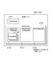
- FIG. 1C is a system configuration diagram including the monitoring camera 1000.
- Reference numeral 2000 denotes a client device indicating an external device according to the present invention.
- the monitoring camera 1000 and the client device 2000 are connected to each other via an IP network 1500 so that they can communicate with each other.
- the client apparatus 2000 transmits various commands such as imaging parameter change, pan head drive, and video streaming start described later to the monitoring camera 1000.
- the monitoring camera 1000 transmits responses to these commands and video streaming to the client device 2000.
- FIG. 1B will be described later.
- FIG. 2A is a diagram illustrating an internal configuration of the surveillance camera according to the present embodiment.
- reference numeral 1001 denotes a control unit, which controls the entire monitoring camera 1000.
- the control unit 1001 is a computer configured with, for example, a CPU.
- Reference numeral 1002 denotes a storage unit (memory).
- the storage unit 1002 is mainly used as a storage region for various data such as a program storage region executed by the control unit 1001, a work region during program execution, and a storage region for image data generated by the imaging unit 1003 described later.
- the 1003 is an imaging unit.
- the imaging unit 1003 converts an analog signal acquired by imaging a subject into digital data, and performs data compression processing by ADCT (adaptive discrete cosine transformation) or the like to generate image data of a captured image, and a storage unit To 1002.
- the imaging unit 1003 issues an image acquisition event to the control unit 1001 after outputting the captured image to the storage unit 1002.
- the imaging unit 1003 can change the imaging direction by an imaging control unit 1006 described later.
- the 1004 is a communication unit.
- the communication unit 1004 is used when various control commands are received from an external device or when a response to each control command is transmitted to the external device (client device).
- the received command includes, for example, designation of the imaging direction of the imaging unit 1003 in relation to the superimposition of the mask image on the captured image.
- the communication unit 1004 transmits a part or the whole of the captured image captured by the imaging unit 1003 to the receiving device (client device) as a distribution image.
- the 1006 is an imaging control unit. It is used to control the pan mechanism 1101, the tilt mechanism 1102, and the zoom mechanism 1103 in accordance with the pan angle, tilt angle, and zoom magnification values input from the control unit 1001. That is, the imaging direction of the imaging unit 1003 can be changed by the imaging control unit 1006. In response to an inquiry from the control unit 1001, the current pan angle value, tilt angle value, and zoom magnification value are provided. In addition, the imaging control unit 1006 identifies the current imaging direction of the imaging unit 1003.
- a mask processing unit 1007 is a mask processing unit.
- a mask processing unit 1007 applies a mask to an appropriate position of image data output from the imaging unit 1003. This mask processing is based on the pan angle, tilt angle, and zoom magnification input by the control unit 1001 to specify the mask position. Further, this mask processing is based on designation of the image cutout position in the image pickup range of the image pickup unit 1003 in the pan / tilt / zoom state, and the size and position of the mask at the image cutout position.
- the mask processing unit 1007 has a valid flag for each mask, and controls to not output a mask when this flag is False.
- FIG. 2 illustrates an example of a preferred embodiment of the monitoring camera according to the present invention, and is not limited thereto.
- Various modifications and changes are possible within the scope of the gist of the present invention, such as including a voice input unit. FIG. 2B will be described later.
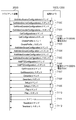
- FIG. 3 illustrates the structure of parameters held in the storage unit 1002 by the monitoring camera 1000 according to the present embodiment.
- the MediaProfile 6100 is a parameter set for storing various setting items of the monitoring camera in association with each other.
- the MediaProfile 6100 holds a ProfileToken that is an ID of the MediaProfile 6100.
- the MediaProfile 6100 holds a VideoSourceConfiguration 6102, a VideoEncoderConfiguration 6103, and a PTZConfiguration 6104.
- the MediaProfile 6100 holds links to various setting items including a distribution image encoder and an audio encoder.
- VideoSource 6101 is a set of parameters indicating the performance of one image sensor included in the surveillance camera.
- the VideoSource 6101 includes a VideoSourceToken that is an ID of the VideoSource 6101 and a Resolution indicating the resolution of image data that can be output by the imaging sensor. Resolution includes Height and Width in which the height and width are expressed in pixels, respectively.
- the VideoSourceConfiguration 6102 is a collection of parameters that associate the VideoSource 6101 provided in the surveillance camera with the MediaProfile 6100.
- the storage unit 1002 holds a plurality of video source settings used for generating a captured image including the resolution of the captured image.
- VideoSourceConfiguration 6102 includes VideoSourceConfigurationToken which is an ID of VideoSourceConfiguration 6102. This VideoSourceConfigurationToken is specific information for specifying the video source setting.
- VideoSourceConfiguration 6102 includes Bounds that specify which part of the image data output from VideoSource 6101 is to be cut out as a distribution image.
- Bounds includes Height and Width representing the height and width of the distribution image cut out from the image data in pixels, and x and y representing the coordinates of the lower left point of the distribution image cut out in pixels from the upper left of the image data as the origin. Including.
- a plurality of pieces of distribution image position information (Bounds position) indicating the position of the distribution image in the captured image are stored in association with specific information (VideoSourceConfigurationToken) for specifying the distribution image position information.
- the storage unit 1002 holds a plurality of video source settings including the reference of the resolution setting of the captured image and the reference of the setting of the cutout position at which the distribution image to be transmitted to the receiving device is extracted from the captured image of the resolution. .
- the VideoEncoderConfiguration 6103 is a collection of parameters that associate settings related to video compression with the MediaProfile 6100.
- the monitoring camera 1000 distributes image data output based on the content of the VideoSourceConfiguration 6102 to the client device 2000. This distribution follows parameters such as a video compression method (for example, JPEG or H.264), a frame rate, or a resolution set in the VideoEncoderConfiguration 6103.
- the PTZConfiguration 6104 is a set of parameters that associates settings related to the pan mechanism 1101, the tilt mechanism 1102, and the zoom mechanism 1103 of the monitoring camera 1000 with the MediaProfile 6100.
- the privacy mask 6105 is a set of parameters that hold a list of parameters related to the mask.
- the privacy mask 6105 includes a privacy mask token that is the ID of the privacy mask 6105, a name that is the name of the privacy mask structure, and a mask that specifies the position and size of the mask with three or more points using a polygon. Further, the privacy mask 6105 includes an enabled flag that specifies whether or not to display the mask on the distribution image, a color that specifies the color of the mask, and a PTZ designating that specifies the position of the pan head.
- PTZDesignation includes PTZConfigurationToken that specifies PTZConfiguration 6104 including the definition of a coordinate system for expressing the head direction (pan, tilt) and zoom magnification. Furthermore, PTZDesignation includes a Position that designates the head direction and zoom magnification according to the coordinate system indicated in the designated PTZConfiguration. Position includes the orientation of the imaging unit 1003, that is, the coordinates of the center point of the image data output from the imaging unit, and the numerical value of the zoom magnification.
- FIG. 4 shows a typical command sequence from the setting start to video distribution between the monitoring camera 1000 and the client apparatus 2000 in the present embodiment.
- the client apparatus 2000 acquires a list of VideoSourceConfiguration 6102 held by the monitoring camera 1000.
- 7101 is a transaction of the GetVideoEncoderConfigurations command. With this command, the client apparatus 2000 acquires a list of VideoEncoderConfiguration 6103 held by the monitoring camera 1000.
- the client apparatus 2000 obtains a list of PTZConfiguration 6104 held by the monitoring camera 1000.
- Reference numerals 7104, 7105, and 706 denote the transactions of the AddVideoSourceConfiguration command, the AddVideoEncoderConfiguration command, and the AddPTZConfiguration command. With these commands, the client apparatus 2000 associates the following three. That is, the three are the desired VideoSourceConfiguration, VideoEncoderConfiguration, and PTZConfiguration for the specified MediaProfile.
- the client apparatus 2000 acquires an address (URI) for the monitoring camera 1000 to acquire a distribution stream based on the specified MediaProfile setting.
- URI address
- 7108 is a transaction of a describe command. By executing this command using the URI acquired in 7107, the client apparatus 2000 requests and acquires information on the content to be streamed by the monitoring camera 1000.
- 7109 is a setup command transaction. By executing this command using the URI acquired in 7107, the transmission method of the stream including the session number is shared between the client apparatus 2000 and the monitoring camera 1000.
- 7110 is a Play command transaction. By executing this command using the session number acquired in 7109, the client apparatus 2000 requests the monitoring camera 1000 to start a stream.
- Reference numeral 7111 denotes a distribution stream.
- the monitoring camera 1000 distributes the stream requested to start in 7110 by the transmission method shared in 7109.
- 7112 is a Teardown command transaction. By executing this command using the session number acquired in 7109, the client apparatus 2000 requests the monitoring camera 1000 to stop the stream.
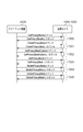
- FIG. 5 shows a typical command sequence for mask setting between the monitoring camera 1000 and the client device 2000 in this embodiment.
- 7200 is a transaction of a GetPrivacyMask command.
- the GetPrivacyMasks command is a command for instructing the client apparatus 2000 to return the following PrivacyMask 6105 to the monitoring camera 1000. That is, all PrivacyMasks 6105 associated with the designated VideoSourceConfiguration 6102 as shown in FIG. 3 are returned.
- the 7201 is a transaction of the CreatePrivacyMask command.
- the CreatePrivacyMask command is a command for the client device 2000 to instruct the monitoring camera 1000 to create a PrivacyMask 6105.
- This PrivacyMask 6105 is created in association with a specified VideoSourceConfiguration 6102.
- the monitoring camera 1000 returns the generated PrivacyMaskToken of the PrivacyMask to the client apparatus 2000.
- the GetPrivacyMaskOptions command is a command for the client device 2000 to instruct the monitoring camera 1000 to return a selection range of each parameter of the PrivacyMask 6105 or an option. Note that what is instructed to be returned here is a selection range or option of each parameter of PrivacyMask 6105 that can be set by ModifyPrivacyMask described later.
- the 7203 is a transaction of GetPrivacyMask.
- the GetPrivacyMask command is an instruction for returning a PrivacyMask 6105 having a specified PrivacyMaskToken.
- the privacy mask 6105 has a designated privacy mask token associated with the video source configuration 6102 designated by the client apparatus 2000 for the monitoring camera 1000.
- the modify privacy masks command is a command for the client device 2000 to instruct the monitoring camera 1000 to edit each parameter included in the privacy mask 6105.
- the monitoring camera 1000 edits the contents of the PrivacyMask 6105 having the PrivacyMaskToken specified by the client apparatus 2000.
- a mask is newly displayed, and the color, size, and position of the mask being displayed are changed. Details of the detailed processing of this command in the monitoring camera 1000 will be described later.
- the 7205 is a transaction of DeletePrivacyMask command.
- the DeletePrivacyMasks command is a command for the client device 2000 to instruct the monitoring camera 1000 to delete the PrivacyMask 6105 created by the CreatePrivacyMask command.
- the monitoring camera 1000 deletes the PrivacyMask 6105 having the PrivacyMaskToken specified by the client apparatus 2000 from the storage device.
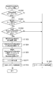
- FIG. 6 shows a processing procedure when the monitoring camera 1000 receives the above-described ModifyPrivacyMask command from the client device 2000.
- This procedure shows a part of a program that is read from the storage unit 1002 and executed by the control unit 1001 that is a computer.
- the storage unit 1002 is a storage medium that stores the program so that the control unit 1001 that is a computer can read and execute the program.
- step S1000 the control unit 1001 determines whether or not the privacy mask 6105 having the privacy mask token specified in the received command exists in the storage unit 1002. If it exists, the control unit 1001 moves the process to step S1060.
- step S1001 the control unit 1001 confirms whether the mask included in the privacy mask 6105 is set correctly. For example, it is determined whether or not three or more points are included, and whether or not each point is plotted in normalized coordinates in Bounds indicated by 5002 in FIG. If not correctly set, the control unit 1001 shifts the processing to step S1060.
- step S1002 the control unit 1001 determines whether or not the VideoSourceConfiguration specified in the received command exists in the storage unit 1002. If not, the control unit 1001 moves the process to step S1060.
- step S1003 the control unit 1001 causes the storage unit 1002 to store the privacy mask specified in the received command.
- step S1004 the control unit 1001 reads Bounds from the VideoSourceConfiguration 6102 including the VideoSourceConfigurationToken specified by the client apparatus 2000.
- This VideoSourceConfigurationToken is specified by the client device 2000 stored in the storage unit 1002. That is, the monitoring camera 1000 receives specific information (VideoSourceConfigurationToken) for specifying the video source setting from the client device 2000.
- step S1005 the control unit 1001 reads the Resolution from the VideoSource 6101 linked (associated) with the VideoSourceConfiguration 6102 specified in the received command.
- This VideoSourceConfiguration 6102 includes the VideoSourceConfigurationToken specified in the received command.
- step S1008 the control unit 1001 determines whether PTZ Designation is specified or omitted in the received command. If specified, the control unit 1001 moves the process to step S1009, and if omitted, moves the process to step S1050.
- This PTZDesignation is imaging direction information indicating the imaging direction. Accordingly, in step S1008, it is determined whether the mask parameter included in the received command includes imaging direction information indicating the imaging direction.
- step S1009 the control unit 1001 reads the pan / tilt / zoom coordinate system from the PTZConfiguration 6104 specified by the PTZConfigurationToken specified in the PTZDesignation. Based on this coordinate system, the control unit 1001 converts each of the pan / tilt / zoom values included in the Position specified in PTZDesignation into a pan angle value, a tilt angle value, and a zoom magnification value.
- step S1050 the control unit 1001 acquires the current pan angle value, tilt angle value, and zoom magnification value from the imaging control unit 1006.
- step S1011 the control unit 1001 executes mask display processing (details are omitted).
- the following three are used as arguments. That is, the first argument is Bounds acquired in step S1004.
- the second argument is the Resolution acquired in step S1005.
- the third argument is the pan angle, tilt angle, zoom angle value acquired in step S1009 or step S1050, and the state of the enabled flag included in the received command.
- step S1008 When step S1008 is YES, the position of the mask image in the imaging range that can be imaged by the imaging unit 1003 is specified based on the following three. That is, the first is PTZ Designation (imaging direction information) included in the received mask parameter. The second is distribution image position information (Bounds position) associated with the VideoSourceConfigurationToken included in the received mask parameter. The third is superposition position information (mask image position) included in the received mask parameter. Note that VideoSourceConfigurationToken is identification information for identifying distribution image position information (Bounds position) indicating the position of the distribution image in the captured image.
- PTZDesignation specifies the imaging direction of the imaging unit 1003 in relation to the superimposition of the mask image on the captured image. In this way, when the designation of the imaging direction is received, the position at which the mask image is superimposed in the imaging range that can be imaged by the imaging unit 1003 is set based on the designated imaging direction.
- the mask position specifies the position of the mask image in the captured image based on the following three.
- the first is distribution image position information (Bounds position) associated with the VideoSourceConfigurationToken included in the received mask parameter.
- the second is superposition position information (mask image position) included in the received mask parameter.
- the third is the current imaging direction of the imaging apparatus acquired from the imaging control unit 1006 in step S1050. In this way, when the designation of the imaging direction of the imaging unit 1003 is not received in relation to the superimposition of the mask image, the control unit 1001 determines the position at which the mask image is superimposed in the imaging range that the imaging unit 1003 can capture.
- the image pickup control unit 1006 sets the image pickup direction specified.
- the control unit 1001 inputs the argument passed in step S1011 to the mask processing unit 1007.
- the mask processing unit 1007 uniquely identifies the position of the mask in the imaging field of view based on the input data, and applies the mask to the image being distributed based on the specification of the enabled flag. . Details of this processing will be described later.
- step S1012 the control unit 1001 executes normal response transmission processing (details are omitted).
- the control unit 1001 transmits a normal response to the received command to the client device 2000 via the communication unit 1004.
- step S1060 the control unit 1001 executes an error response transmission process (details are omitted).
- the control unit 1001 transmits an error response to the received command to the client device 2000 via the communication unit 1004.
- step S1011 is diagrams for explaining a method for specifying the coordinates of the mask. The process of step S1011 will be described with reference to FIGS.
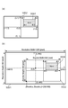
- FIG. 8 (a) shows a mask coordinate specification method in the privacy mask.
- Mask is specified by three or more points plotted in the normalized coordinate system in the distribution image 5002 cut out by Bounds out of the image data output by VideoSource 6101. These points are plotted in a normalized coordinate system in which both the horizontal direction (x) and the vertical direction (y) are normalized to ⁇ 1.0 to +1.0, with the right direction and the upward direction being plus.
- FIG. 8B is obtained by superposing the Mask 5004 described in FIG. 8A on the image data 5001 output from the VideoSource 6101.
- Resolution. Height is 960 pixels, Resolution. Let Width be 1280 pixels. Also, Bounds. Height is 480 pixels, Bounds. Width is 640 pixels, Bounds. x is 500 pixels, Bounds. Let y be 900 pixels. At this time, when calculating the position (x2, y2) of each point of the Mask 5004 in the Resolution pixel coordinate system with the center point of the image data 5001 as the origin, the calculation formulas are as follows. Mask.
- the direction (x, y) in the imaging direction indicates the center point of the image data 5001.
- zoom * tilt angle conversion coefficient The zoom / pan angle conversion coefficient and the zoom / tilt angle conversion coefficient of the imaging unit 1003 are used to convert the x and y positions of the mask in the image data into pan and tilt angle coordinates, respectively. It is a coefficient based on characteristics.
- the mask position (x, y) designated by the coordinates in the distribution image cut out by Bounds is converted to the position (x3, y3) designated by the coordinates of the imageable field of view of the imaging device. Can do.
- This conversion is performed based on information of Bounds, Resolution, and Position. That is, the monitoring camera 1000 can uniquely specify the position of the mask in the imageable field of view.
- the control unit 1001 sets the position where the mask image is superimposed in the imaging range that can be imaged by the imaging unit 1003 based on the video source setting specified by the received specific information and the specified imaging direction.
- the client can specify the imaging direction (for example, pan / tilt position) of the camera in relation to the mask setting.
- the imaging direction for example, pan / tilt position
- the client can specify the mask position without actually changing the imaging direction of the camera. Therefore, it is possible to collectively perform a process of setting a photographing prohibited area for each of the picked-up images photographed in different photographing directions.
- the monitoring camera 1000 can uniquely specify the position of the mask set from the client device regardless of the presence or absence of the function of cutting out and distributing a specific portion of the image data generated by the imaging unit 1003 using Bounds. It becomes. As a result, the image pickup apparatus has an effect of allowing the client apparatus to set a common mask processing function regardless of whether or not Bounds is supported.
- the embodiment of the present invention has been described with reference to a surveillance camera that holds a privacy mask, which is a parameter for a mask processing function, in association with a video source configuration.
- the surveillance camera having the function of changing the imaging range of the imaging unit by panning, tilting, or zooming is exemplified, but this is not restrictive.
- the present invention is also applicable to a surveillance camera that does not have pan, tilt, and zoom.
- FIG. 1B is a diagram illustrating a monitoring camera 1200 according to the second embodiment.
- FIG. 2B is a diagram showing an internal configuration of the monitoring camera 1200.
- FIG. 4 shows a typical command sequence from the setting start to video distribution between the monitoring camera 1200 and the client device 2000 in the present embodiment.
- FIG. 7 shows processing when the monitoring camera 1200 receives the above-described ModifyPrivacyMask command from the client device 2000.
- step S2011 the control unit 1001 executes mask display processing using the Bounds acquired in step S1004, the Resolution acquired in step S1005, and the state of the enabled flag included in the received command as arguments. Details of the mask display process are omitted.
- the control unit 1001 inputs the argument passed in step S1011 to the mask processing unit 1007.
- the mask processing unit 1007 uniquely identifies the position of the mask in the imaging field based on the input data, and masks the image being distributed based on the specification of the enabled flag.
- step S2011 will be described with reference to FIG.
- the mask position (x, y) specified by the coordinates in the distribution image cut out by Bounds by the calculation flow described in FIGS. Can be converted to the position (x2, y2) specified by. This conversion is performed based on information of Bounds and Resolution. That is, the monitoring camera 1200 can uniquely specify the position of the mask in the imageable field of view. That is, when the imaging unit 1003 does not have a function of changing the imaging direction, the position of the mask image in the imaging range that can be imaged by the imaging unit 1003 is specified based on the following two.
- the first is distribution image position information (Bounds position) associated with the VideoSourceConfigurationToken included in the received mask parameter.
- the second is superposition position information (mask image position) included in the received mask parameter.
- VideoSourceConfigurationToken is identification information for identifying distribution image position information (Bounds position) indicating the position of the distribution image in the captured image.
- the surveillance camera has a common mask processing function regardless of whether or not there is a function of changing the imaging range of the imaging unit 1003 including pan, tilt, and zoom. It becomes possible.
- the image pickup apparatus can cause the client apparatus to set a common mask processing function regardless of whether or not PTZDesignation including PTZConfiguration and Position is supported.
- the operation of the surveillance camera in which the present invention is implemented is shown in Examples 1 and 2, but the embodiment is not necessarily limited to the above, and may be partially changed. That is, (1)
- the monitoring camera 1000 in the embodiment uses angle coordinates for pan and tilt and magnification coordinates for zoom coordinates in PTZConfiguration, but this is not restrictive. For example, normalized coordinates that normalize the entire range from ⁇ 1.0 to +1.0 may be used. (2)
- the change of the imaging direction in the imaging apparatus in the embodiment has been described by exemplifying a pan head apparatus or the like, but is not limited thereto. What is called electronic PTZ which implement
- a computer of a system or apparatus that reads and executes a computer-executable instruction recorded on a recording medium (for example, a storage device that does not perform computer-readable temporary recording) It may be realized by. Execution of the instruction by the computer realizes the functions of one or more of the above-described embodiments of the present invention.
- the present invention may be realized by a method executed by a computer of a system or apparatus.
- the functions of one or more of the above-described embodiments of the present invention are realized by reading a computer-executable instruction from a recording medium.
- the computer can be composed of one or more Central Processing Units (CPU), Micro Processing Units (MPU), or other circuits.
- the computer can be constituted by a network of separated computers or a separated computer processor.
- the computer-executable instructions are provided to the computer via, for example, a network or from a recording medium.
- This recording medium is, for example, one or more hard disks, Random Access Memory (RAM), Read Only Memory (ROM), distributed computing system storage, optical disc (for example, Compact Disc (CD), Digital Versatile Disc (DVD) Or Blu-ray Disc (BD) (registered trademark)), flash memory, memory card, and the like.
- Control unit 1007 Mask processing unit 2000 Client device 5004 Mask 6105 PrivacyMask
Abstract
撮像装置やクライアントアプリケーションの機種毎にマスク処理機能の実装やインタフェースが異なるため、機種が異なるカメラとクライアントとの間でマスクの設定ができないことがある。 撮像画像へのマスク画像の重畳に関連して前記撮像部の撮像方向の指定を受信する受信部と、前記受信部が前記撮像方向の指定を受信した場合には、前記撮像部が撮像可能な撮像範囲において前記マスク画像を重畳する位置を、指定された前記撮像方向に基づいて設定する設定部とを有する撮像装置。
Description
本発明は、撮像画像を配信可能な撮像装置に関し、特に撮像装置が撮像する撮像画像にマスク画像を重畳する機能に関する。
従来、撮像画像の配信先でその領域を特定できないようにするためのマスク処理機能が提供されている。マスク処理機能には、例えば、対象領域をOSD(On ScreenDisplay:オンスクリーン表示)によって塗りつぶす処理や、対象領域の画質低下処理、フィルター処理などの機能がある。
例えば、特許文献1では、撮像部から出力される画像データにおける撮影禁止領域の画質低減処理を行うことが開示されている。
特許文献1に記載のカメラはネットワークを介して記録装置に接続される。記録装置は、カメラから入力された撮像画像における撮影禁止位置を指定する。カメラは、記録装置によって指定された位置に、撮影禁止領域を設定する。
しかしながらカメラやクライアントアプリケーション毎にマスク処理機能の実装やインタフェースが異なる。
従来の方法では、カメラとクライアントとが共有する座標系を用いてマスク位置を特定する。この場合、クライアントは、ユーザ等によって入力されたマスク位置の情報を、カメラとクライアントとが共有する座標系における座標値に置き換えてカメラに送信する必要があった。また、それぞれ異なる座標系を有する複数のカメラにマスク設定を行うためには、クライアントは各カメラが有する座標系に合わせてマスク画像の座標位置を指定する必要があり、クライアントでの処理が煩雑になるという課題があった。
上記課題を解決するために、本発明による送信装置は、撮像方向を変更可能な撮像部と、前記撮像部が撮像した撮像画像を受信装置に送信する送信部と、前記撮像画像にマスク画像の重畳に関連して、前記撮像部の撮像方向の指定を受信する受信部と、前記受信部が前記撮像方向の指定を受信した場合には、前記撮像部が撮像可能な撮像範囲において前記マスク画像を重畳する位置を、指定された前記撮像方向に基づいて設定する設定部とを有する。
本発明の詳細な構成は、添付の図面の参照、及び、以下の実施例の記載を用いて説明する。
本発明によれば、クライアントにおけるマスク画像の座標位置の指定の煩雑さを軽減することができる。
以下に、本発明の実施の形態を説明する。
図1(a)は、本発明の実施形態にかかわる監視カメラを示す図である。1101は撮像部の向きをパン方向に、同じく1102はチルト方向に変更する機構であり、1103はズーム機構である。
図1(c)は、監視カメラ1000を含むシステム構成図である。2000は、本発明における外部機器を示すクライアント装置である。監視カメラ1000とクライアント装置2000は、IPネットワーク網1500を介して相互に通信可能な状態に接続されている。クライアント装置2000は、監視カメラ1000に対して、後述する撮像パラメータ変更や雲台駆動、映像ストリーミング開始等の各種コマンドを送信する。監視カメラ1000は、それらのコマンドに対するレスポンスや映像ストリーミングをクライアント装置2000に送信する。図1(b)については、後述する。
図2(a)は、本実施形態に関わる監視カメラの内部構成を示す図である。
図2(a)において、1001は制御部であり、監視カメラ1000の全体の制御を行う。制御部1001は、例えばCPUで構成されるコンピュータである。
1002は記憶部(メモリ)である。記憶部1002は、主に制御部1001が実行するプログラム格納領域、プログラム実行中のワーク領域、後述する撮像部1003が生成する画像データの格納領域等、様々なデータの格納領域として使用される。
1003は撮像部である。撮像部1003は、被写体を撮影して取得したアナログ信号をデジタルデータに変換し、また、ADCT(適応離散コサイン変換)等によりデータの圧縮処理を行って撮像画像の画像データを生成し、記憶部1002に出力する。撮像部1003は、撮像画像を記憶部1002に出力した後、制御部1001に画像取得イベントを発行する。撮像部1003は後述の撮像制御部1006によって撮像方向を変更可能である。
1004は通信部である。通信部1004は、各種制御コマンドを外部機器から受信する場合や、各制御コマンドに対するレスポンスを外部機器(クライアント装置)へ送信する場合に、使用される。受信するコマンドには例えば、撮像画像へのマスク画像の重畳に関連して撮像部1003の撮像方向の指定が含まれる。通信部1004は、撮像部1003が撮像した撮像画像の一部又は全体を配信画像として受信装置(クライアント装置)に送信する。
1006は撮像制御部である。制御部1001から入力するパン角度、チルト角度、ズーム倍率の値に従って、パン機構1101、チルト機構1102、及びズーム機構1103を制御するために使用される。すなわち、撮像制御部1006により撮像部1003の撮像方向が変更可能である。また制御部1001の問い合わせに応じて、現在のパン角度値、チルト角度値、ズーム倍率値を提供する。また、撮像制御部1006は、撮像部1003の現在の撮像方向を特定する。
1007はマスク処理部である。マスク処理部1007は、撮像部1003が出力する画像データの適切な位置にマスクを施す。このマスク処理は、制御部1001がマスク位置を特定するべく入力するパン角度、チルト角度、ズーム倍率に基づく。さらに、このマスク処理は、当該パン・チルト・ズーム状態での撮像部1003の撮像範囲における画像の切り出し位置、画像の切り出し位置におけるマスクの大きさと位置の指定に基づく。マスク処理部1007は、マスク毎に有効フラグを有し、本フラグがFalseの場合はマスクを出力しないように制御する。
以上、図2を参照し監視カメラ1000の内部構成について説明したが、図2に示す処理ブロックは、本発明における監視カメラの好適な実施形態の一例を説明したものでありこの限りではない。音声入力部を備えるなど、本発明の要旨の範囲内で、種々の変形及び変更が可能である。図2(b)については、後述する。
本実施例にて使用するコマンド、パラメータ等の名称と内容を以下に説明する。
図3は、本実施例における監視カメラ1000が記憶部1002に保持するパラメータの構造を図示している。
MediaProfile6100とは、監視カメラの各種設定項目を関連づけて記憶するためのパラメータセットである。MediaProfile6100は、MediaProfile6100のIDであるProfileTokenを保持する。さらに、MediaProfile6100は、VideoSourceConfiguration6102、VideoEncoderConfiguration6103、PTZConfiguration6104を保持する。さらに、MediaProfile6100は、このほか、配信画像のエンコーダや音声のエンコーダを含む各種設定項目へのリンクを保持する。
VideoSource6101とは、監視カメラが備える1つの撮像センサーの性能を示すパラメータの集合体である。VideoSource6101は、VideoSource6101のIDであるVideoSourceTokenと、撮像センサーが出力可能な画像データの解像度を示すResolutionを含む。Resolutionは、高さと幅をそれぞれピクセルで表したHeight、Widthを含む。
VideoSourceConfiguration6102とは、監視カメラが備えるVideoSource6101をMediaProfile6100に関連付けるパラメータの集合体である。記憶部1002は、撮像画像の解像度を含み撮像画像を生成するために用いられるビデオソース設定を複数保持する。VideoSourceConfiguration6102は、VideoSourceConfiguration6102のIDであるVideoSourceConfigurationTokenを含む。この、VideoSourceConfigurationTokenは、ビデオソース設定を特定するための特定情報である。VideoSourceConfiguration6102は、VideoSource6101が出力する画像データのうち、どの部分を切り出して配信画像とするかを指定するBoundsを含む。Boundsは、画像データから切り出す配信画像の高さと幅をそれぞれピクセルで表したHeight、Widthと、画像データの左上を原点として、切り出す配信画像の左下の点の座標をピクセルで表したx,yを含む。なお、撮像画像における配信画像の位置を示す配信画像位置情報(Boundsの位置)を、配信画像位置情報を特定するための特定情報(VideoSourceConfigurationToken)と対応付けて複数記憶される。このように記憶部1002は、撮像画像の解像度の設定の参照と、当該解像度の撮像画像から受信装置に送信する配信画像を切り出す切出位置の設定の参照とを含むビデオソース設定を複数保持する。
VideoEncoderConfiguration6103とは、ビデオ圧縮に関する設定をMediaProfile6100に関連付けるパラメータの集合体である。監視カメラ1000は、VideoSourceConfiguration6102の内容に基づいて出力される画像データをクライアント装置2000に配信する。この配信は、本VideoEncoderConfiguration6103内に設定されるビデオ圧縮方式(例えばJPEGやH.264)、フレームレート、或いは解像度等のパラメータに従う。
PTZConfiguration6104とは、監視カメラ1000のパン機構1101、チルト機構1102、及びズーム機構1103に関する設定をMediaProfile6100に関連付けるパラメータの集合体である。PTZConfiguration6104は、パン機構、チルト機構、及びズーム機構における実際のパン・チルト角度値とズーム倍率値を表現する座標系に関する情報を含む。本例においてはパン範囲x=-180~+180[度]、チルト範囲y=-90~+90[度]の角度座標と、ズームz=1~100[倍]の倍率座標であるとする。
PrivacyMask6105とは、マスクに関連する一覧のパラメータを保持するパラメータの集合体である。PrivacyMask6105は、PrivacyMask6105のIDであるPrivacyMaskToken、PrivacyMask構造体の名称であるName、マスクの位置及び大きさをポリゴンによって3つ以上の点で指定するMaskを含む。さらに、PrivacyMask6105は、マスクを配信画像上に表示するか否かを指定するフラグであるEnabled、マスクの色を指定するColor、雲台の位置を特定するPTZDesignationを含む。
PTZDesignationは、雲台の向き(パン、チルト)とズーム倍率を表現するための座標系の定義を含むPTZConfiguration6104を指定するPTZConfigurationTokenを含む。さらに、PTZDesignationは、指定されるPTZConfigurationに示される座標系によって雲台の向きとズーム倍率を指定するPositionを含む。Positionは、撮像部1003の向き、すなわち撮像部が出力する画像データの中心点の座標と、ズーム倍率の数値を含む。
図4は、本実施例における監視カメラ1000とクライアント装置2000の間における、設定開始から映像配信までの典型的なコマンドシーケンスを示している。
7100は、GetVideoSourceConfigurationsコマンドのトランザクションである。このコマンドにより、クライアント装置2000は、監視カメラ1000が保持する保持するVideoSourceConfiguration6102のリストを取得する。
7101は、GetVideoEncoderConfigurationsコマンドのトランザクションである。このコマンドにより、クライアント装置2000は、監視カメラ1000が保持する保持するVideoEncoderConfiguration6103のリストを取得する。
7102は、GetConfigurationsコマンドのトランザクションである。このコマンドにより、クライアント装置2000は、監視カメラ1000が保持する保持するPTZConfiguration6104のリストを取得する。
7103は、CreateProfileコマンドのトランザクションである。このコマンドにより、クライアント装置2000は、監視カメラ1000に新たなMediaProfile6100を作成し、そのProfileTokenを得る。
7104、7105、706は、AddVideoSourceConfigurationコマンド、AdddVideoEncoderConfigurtionコマンド、及びAddPTZConfigurationコマンドの各トランザクションである。これらのコマンドにより、クライアント装置2000は、以下の3つを関連付ける。すなわち、3つとは、指定したMediaProfileに所望のVideoSourceConfiguration、VideoEncoderConfiguration、及びPTZConfigurationである。
7107は、GetStreamUriコマンドのトランザクションである。このコマンドにより、クライアント装置2000は、指定したMediaProfileの設定に基づいて監視カメラ1000が配信ストリームを取得するためのアドレス(URI)を取得する。
7108は、Describeコマンドのトランザクションである。7107において取得したURIを使用してこのコマンドを実行することにより、クライアント装置2000は、監視カメラ1000がストリーム配信するコンテンツの情報を要求し取得する。
7109は、Setupコマンドのトランザクションである。7107において取得したURIを使用してこのコマンドを実行することにより、クライアント装置2000と監視カメラ1000の間で、セッション番号を含むストリームの伝送方法が共有される。
7110は、Playコマンドのトランザクションである。7109において取得したセッション番号を使用してこのコマンドを実行することにより、クライアント装置2000は、監視カメラ1000に対してストリームの開始を要求する。7111は、配信ストリームである。監視カメラ1000は、7110において開始を要求されたストリームを、7109において共有された伝送方法によって配信する。
7112は、Teardownコマンドのトランザクションである。7109において取得したセッション番号を使用してこのコマンドを実行することにより、クライアント装置2000は、監視カメラ1000に対してストリームの停止を要求する。
図5は、本実施例における監視カメラ1000とクライアント装置2000の間における、マスク設定の典型的なコマンドシーケンスを示している。
7200は、GetPrivacyMaskコマンドのトランザクションである。
GetPrivacyMasksコマンドは、クライアント装置2000が監視カメラ1000に対して、以下のPrivacyMask6105を返送するよう指示するコマンドである。すなわち、返却されるのは、図3に示されるような指定のVideoSourceConfiguration6102に関連づけられている全てのPrivacyMask6105である。
7201は、CreatePrivacyMaskコマンドのトランザクションである。CreatePrivacyMaskコマンドとは、クライアント装置2000が監視カメラ1000に対して、PrivacyMask6105を作成することを指示するためのコマンドである。このPrivacyMask6105は、指定のVideoSourceConfiguration6102に関連付けて作成される。CreatePrivacyMaskコマンドの実行により、監視カメラ1000はクライアント装置2000へ生成したPricasyMaskのPrivacyMaskTokenを返送する。
7202は、GetPrivacyMaskOptionsのトランザクションである。GetPrivacyMaskOptionsコマンドは、クライアント装置2000が監視カメラ1000に対して、PrivacyMask6105の各パラメータの選択範囲、或いは選択肢を返送するよう指示するコマンドである。なお、ここで返送するよう指示されるのは、後述するModifyPrivacyMaskによって設定可能なPrivacyMask6105の各パラメータの選択範囲、或いは選択肢である。
7203は、GetPrivacyMaskのトランザクションである。GetPrivacyMaskコマンドは、指定のPrivacyMaskTokenを持つPrivacyMask6105を返送するよう指示するコマンドである。PrivacyMask6105は、クライアント装置2000が監視カメラ1000に対して指定のVideoSourceConfiguration6102に関連づけられている、指定のPrivacyMaskTokenを持つ。
7204は、ModifyPrivacyMaskのトランザクションである。ModifyPrivacyMasksコマンドは、クライアント装置2000が監視カメラ1000に対してPrivacyMask6105に含まれる各パラメータの編集を指示するコマンドである。ModifyPrivacyMaskの実行により、監視カメラ1000はクライアント装置2000が指定したPrivacyMaskTokenを持つPrivacyMask6105の内容を編集する。この編集により、マスクを新たに表示したり、表示中のマスクの色や大きさ、位置を変更したりする。監視カメラ1000における本コマンドの詳細処理の詳細は後述する。
7205は、DeletePrivacyMaskコマンドのトランザクションである。DeletePrivacyMasksコマンドは、クライアント装置2000が監視カメラ1000に対してCreatePrivacyMaskコマンドによって作成されたPrivacyMask6105の削除を指示するコマンドである。DeletePrivacyMaskの実行により、監視カメラ1000はクライアント装置2000が指定したPrivacyMaskTokenを持つPrivacyMask6105を記憶装置から削除する。
図6は、監視カメラ1000が前述のModifyPrivacyMaskコマンドをクライアント装置2000から受信した場合の処理手順を示している。この手順は、コンピュータである制御部1001が記憶部1002から読み出して実行するプログラムの一部を示す。記憶部1002は、このプロラムを、コンピュータである制御部1001が読み出して実行することができるように記憶した記憶媒体である。
ステップS1000において制御部1001は、受信したコマンドに指定されているPrivacyMaskTokenを持つPrivacyMask6105が記憶部1002に存在するかどうか判定する。存在する場合制御部1001は、処理をステップS1060に移す。
ステップS1001において制御部1001は、PrivacyMask6105に含まれるMaskが正しく設定されているかどうか確認する。例えば3点以上の点を含むかどうか、また各点は、図8の5002に示すBoundsにおける正規化座標内にプロットされているかどうかを判定する。正しく設定されていなかった場合制御部1001は、処理をステップS1060に移す。
ステップS1002において制御部1001は、受信したコマンドに指定されているVideoSourceConfigurationが記憶部1002に存在するかどうか判定する。存在しなかった場合制御部1001は、処理をステップS1060に移す。
ステップS1003において制御部1001は、受信したコマンドに指定されているPrivacyMaskを記憶部1002に記憶させる。
ステップS1004において制御部1001は、クライアント装置2000が指定したVideoSourceConfigurationTokenを含むVideoSourceConfiguration6102から、Boundsを読みだす。このVideoSourceConfigurationTokenは、記憶部1002に記憶されているクライアント装置2000により指定される。すなわち、監視カメラ1000はビデオソース設定を特定するための特定情報(VideoSourceConfigurationToken)をクライアント装置2000から受信する。
ステップS1005において制御部1001は、受信したコマンドに指定されているVideoSourceConfiguration6102にリンク(関連付け)されているVideoSource6101からResolutionを読みだす。このVideoSourceConfiguration6102は、受信したコマンドに指定されているVideoSourceConfigurationTokenを含む。
ステップS1008において制御部1001は、受信したコマンドにPTZDesigntionが指定されているか、或いは省略されているか判定する。指定されている場合、制御部1001はステップS1009に、省略されている場合はステップS1050にそれぞれ処理を移す。このPTZDesigntionは、撮像方向を示す撮像方向情報である。したがって、ステップS1008では、受信したコマンドに含まれるマスクパラメータに撮像方向を示す撮像方向情報が含まれているか判定する。
ステップS1009において制御部1001は、PTZDesignationに指定されているPTZConfigurationTokenで特定されるPTZConfiguration6104から、パン・チルト・ズームの座標系を読み出す。制御部1001は、本座標系に基づいてPTZDesignationに指定されているPositionに含まれるパン・チルト・ズームの各値を、それぞれパン角度値、チルト角度値、ズーム倍率値に変換する。
ステップS1050において制御部1001は、撮像制御部1006より現在のパン角度値、チルト角度値、ズーム倍率値を取得する。
ステップS1011において制御部1001は、マスク表示処理(詳細は省略する)を実行する。このマスク表示処理では、以下の3つを引数として用いる。すなわち、1つ目の引数は、ステップS1004で取得したBoundsである。2つ目の引数は、ステップS1005で取得したResolutionである。3つ目の引数は、ステップS1009或いはステップS1050にて取得したパン角度、チルト角度、ズーム角度値、及び受信したコマンドに含まれているEnabledフラグの状態である。
ステップS1008がYESの場合、撮像部1003が撮像可能な撮像範囲におけるマスク画像の位置は、以下の3つに基づいて特定される。すなわち、1つ目は、受信したマスクパラメータに含まれるPTZDesigntion(撮像方向情報)である。2つ目は、受信したマスクパラメータに含まれるVideoSourceConfigurationTokenに対応付けられた配信画像位置情報(Boundsの位置)である。3つ目は、受信したマスクパラメータに含まれる重畳位置情報(マスク画像の位置)である。なお、VideoSourceConfigurationTokenは、撮像画像における配信画像の位置を示す配信画像位置情報(Boundsの位置)を特定するための特定情報である。このように、PTZDesignationは、撮像画像へのマスク画像の重畳に関連して撮像部1003の撮像方向を指定する。このようにして、撮像方向の指定を受信した場合には、撮像部1003が撮像可能な撮像範囲においてマスク画像を重畳する位置を、指定された撮像方向に基づいて設定する。
ステップS1008がNOの場合、マスク位置は、以下の3つに基づいて撮像画像におけるマスク画像の位置を特定する。すなわち、1つ目は、受信したマスクパラメータに含まれるVideoSourceConfigurationTokenに対応付けられた配信画像位置情報(Boundsの位置)である。2つ目は、受信したマスクパラメータに含まれる重畳位置情報(マスク画像の位置)である。また、3つ目は、ステップS1050で撮像制御部1006より取得した現在の撮像装置の撮像方向である。このようにして、マスク画像の重畳に関連して撮像部1003の撮像方向の指定を受信しない場合には、制御部1001は、撮像部1003が撮像可能な撮像範囲においてマスク画像を重畳する位置を、撮像制御部1006が特定した撮像方向に基づいて設定する。
マスク表示処理において制御部1001は、ステップS1011において渡された引数をマスク処理部1007に入力する。後述の図8、図9に関する説明の通り、マスク処理部1007は、入力データに基づいて撮像視野におけるマスクの位置を一意に特定し、Enabledフラグの指定に基づいて配信中の画像にマスクを施す。本処理の詳細は後述する。
ステップS1012において制御部1001は、正常レスポンス送信処理(詳細は省略する)を実行する。正常レスポンス送信処理において制御部1001は、通信部1004を介してクライアント装置2000に対して、受信コマンドに対する正常レスポンスを送信する。
ステップS1060において制御部1001は、エラーレスポンス送信処理(詳細は省略する)を実行する。エラーレスポンス送信処理において制御部1001は、通信部1004を介してクライアント装置2000に対して、受信コマンドに対するエラーレスポンスを送信する。
図8、図9はマスクの座標の特定方法を説明する図である。図8、図9を参照しながら、ステップS1011の処理を説明する。
図8(a)は、PrivacyMaskにおける、Maskの座標指定方法を示している。Maskは、VideoSource6101が出力する画像データをうち、Boundsによって切り出される配信画像5002内を、正規化座標系でプロットされる点3点以上で指定される。これらの点は、水平方向(x)・垂直方向(y)のそれぞれを右向き・上向きをプラスとして、ともに-1.0~+1.0に正規化した正規化座標系でプロットされる。例として、図5(a)におけるMask5004は(x,y)=(0.2,0.8)、(0.8,0,8)、(0.2,0.1)、及び(0.8,0.1)の点1~4にて指定されている。
図8(b)は、VideoSource6101が出力する画像データ5001上に、図8(a)で説明したMask5004を重ねたものである。例として、Resolution.Heightを960ピクセル、Resolution.Widthを1280ピクセルであるとする。また、Bounds.Heightを480ピクセル、Bounds.Widthを640ピクセル、Bounds.xを500ピクセル、Bounds.yを900ピクセルであるとする。このとき、画像データ5001の中心点を原点としたResolutionのピクセル座標系で、Mask5004の各点の位置(x2,y2)を計算する場合、計算式はそれぞれ以下の通りとなる。
Mask.x2=((Bounds.x-Resolution.Width/2 )+Bounds.Width/2 )+Bounds.Width/2* Mask.x
Mask.y2=((Bounds.y-Resolution.Height/2)-Bounds.Height/2)+Bounds.Height/2*Mask.y
このとき、画像データから配信画像を切り出す機能に対応していない撮像装置であった場合は、Bounds=Resolutionとなり、上記の計算式は次のように表すことができる。
Mask.x2=Resolution.Width/2*Mask.x
Mask.y2=Resolution.Height/2*Mask.y
例として図8(b)におけるMask5004は(x2,y2)=(244,372)、(436,372)、(436,204)、及び(244,204)の4点にて表現される。
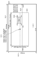
図9は、撮像部1003の撮像可能な全範囲5000において、図8(b)に示される画像データ5001を、Positionに指定される撮像方向の向き(パン=x・チルト=y)とズーム倍率(y)に基づいて重ねたものである。撮像方向の向き(x,y)は、画像データ5001の中心点を示す。Positionの座標系は、PTZConfigurationに含まれる座標系を用い、本例においてはパン範囲x=-180~+180[度]、チルト範囲y=-90~+90[度]の角度座標と、ズームz=1~100[倍]の倍率座標であるとする。例として、Position.x=-20[度]、Position.y=+10[度]、Position.z=1.2[倍]であるとする。このとき、撮像部1003の撮像可能な全範囲5000の中心点を原点として、PTZConfigurationに示される座標系で、Mask5004の各点の位置(x3,y3)を計算する場合、計算式はそれぞれ以下のとおりとなる。
Mask.x3=Position.x+Mask.x2/Resolution.Width/2/Position.Zoom*パン角度変換係数
Mask.y3=Position。y+Mask。y2/Resolution.Height/2/Position.Zoom*チルト角度変換係数
ズーム・パン角度変換係数、及びズーム・チルト角度変換係数は、画像データにおけるマスクのx,y位置を、それぞれパン、チルトの角度座標に変換するための、撮像部1003の特性に基づく係数である。本例ではそれぞれ90、180であるとし、図9におけるMask5004は(x3,y3)=(38.19,68.13)、(82.19,68.13)、(82.19,41.88)、及び(38.19,41.88)の4点にて表現される。
以上、例として計算の流れを図8(a)(b)、図9により説明した。このように、Boundsによって切り出された配信画像内の座標によって指定されるマスクの位置(x,y)を、撮像装置の撮像可能視野の座標によって指定される位置(x3,y3)に変換することができる。この変換は、Bounds、Resolution、Positionの情報を元に行われる。すなわち監視カメラ1000は、撮像可能視野におけるマスクの位置を一意に特定することができる。制御部1001は、撮像部1003が撮像可能な撮像範囲においてマスク画像を重畳する位置を、受信した特定情報によって特定されるビデオソース設定と特定した撮像方向とに基づいて設定する。
以上に示した本実施例に係るマスク設定処理によれば、以下の効果が得られる。本実施例によれば、マスク設定に関連して、クライアントがカメラの撮像方向(例えば、パン・チルト位置)を指定することができる。このようにして、異なる撮像方向で撮影される撮像画像のそれぞれに撮影禁止領域を設定する場合に、実際にカメラの撮像方向を変更しなくても、クライアントがマスク位置を指定することができる。従って、異なる撮像方向で撮影される撮像画像のそれぞれに撮影禁止領域を設定する処理を一括して行うことができる。
監視カメラ1000は、撮像部1003によって生成された画像データのうち、Boundsによって特定の部分を切り出して配信する機能の有無関わらず、クライアント装置から設定されたマスクの位置を一意に特定することが可能となる。これによって撮像装置は、Boundsのサポート有無に関わらず、クライアント装置に共通のマスク処理機能の設定をさせることができるという効果がある。
実施例1において、マスク処理機能用のパラメータであるPrivacyMaskをVideoSourceConfigurationに関連付けて保持する監視カメラに言及しながら、本発明の実施の形態を説明した。
実施例1ではパン、チルト、或いはズームによって撮像部の撮像範囲を変更できる機能を有する監視カメラを例示しているが、この限りではない。パン、チルト、ズームを有しない監視カメラに対しても本発明は適用可能である。
以上の点を考慮した本発明の第2の実施の形態を以下に説明する。尚、実施例1と同じ部分については説明を省略する。
図1(b)は、実施例2に係る監視カメラ1200示す図である。
図2(b)は、監視カメラ1200の内部構成を示す図である。
図4は、本実施例における監視カメラ1200とクライアント装置2000の間における、設定開始から映像配信までの典型的なコマンドシーケンスを示している。
図7は、監視カメラ1200が前述のModifyPrivacyMaskコマンドをクライアント装置2000から受信した場合の処理を示している。
ステップS2011において制御部1001は、ステップS1004で取得したBounds、ステップS1005で取得したResolution、及び受信したコマンドに含まれているEnabledフラグの状態を引数としてマスク表示処理を実行する。マスク表示処理の詳細は省略する。
マスク表示処理において制御部1001は、ステップS1011において渡された引数をマスク処理部1007に入力する。前述の図5に関する説明の通り、マスク処理部1007は、入力データに基づいて撮像視野におけるマスクの位置を一意に特定し、Enabledフラグの指定に基づいて配信中の画像にマスクを施す。
図5を参照しながら、ステップS2011の処理を説明する。
監視カメラ1200は、撮像部1003の撮像範囲の変更が行えないため、図8(b)における画像データ5001=撮像可能視野となる。したがって、図8(a)(b)に説明した計算の流れにより、Boundsによって切り出された配信画像内の座標によって指定されるマスクの位置(x,y)を、撮像装置の撮像可能視野の座標によって指定される位置(x2,y2)に変換することができる。この変換は、Bounds、Resolutionの情報を元に行われる。すなわち監視カメラ1200は、撮像可能視野におけるマスクの位置を一意に特定することができる。すなわち、撮像部1003が、撮像方向を変更する機能を有さない場合は、以下の2つに基づいて、撮像部1003が撮像可能な撮像範囲におけるマスク画像の位置を特定する。すなわち、1つ目は、受信したマスクパラメータに含まれるVideoSourceConfigurationTokenに対応付けられた配信画像位置情報(Boundsの位置)である。2つ目は、受信したマスクパラメータに含まれる重畳位置情報(マスク画像の位置)である。なお、VideoSourceConfigurationTokenは、撮像画像における配信画像の位置を示す配信画像位置情報(Boundsの位置)を特定するための特定情報である。
以上に示した本実施例に係るマスク設定処理によれば、監視カメラは、パン・チルト・ズームを含む撮像部1003の撮像範囲を変更する機能の有無に関わらず、共通のマスク処理機能を有することが可能となる。これによって、撮像装置は、PTZConfigurationやPositionを含むPTZDesignationのサポート有無に関わらず、クライアント装置に共通のマスク処理機能の設定をさせることができるという効果がある。
以上、本発明を実装した監視カメラの動作を実施例1~2に示したが、実施形態は必ずしも上述の限りでなく、部分的に変更されてもよい。即ち、
(1) 実施例中の監視カメラ1000は、PTZConfigurationにおいてパン、チルトにそれぞれ角度座標、ズーム座標に倍率座標を使用するようにしているがこの限りではない。例えば全範囲を-1.0~+1.0に正規化する正規化座標を用いてもよい。
(2) 実施例中の撮像装置における撮像方向の変更は、雲台装置等を例示して説明しているがこの限りではない。撮像画像の一部を電子的に切り出すことで実現する、いわゆる電子PTZによるものであってもよい。
(3) 図8、図9の説明において、マスクの位置を一意に特定するための計算式を説明しているが、この限りではない。機種毎のマスク処理部1007のアルゴリズム、仕様等に基づいて、マスク位置の特定方法は異なり、マスクの位置を特定するために必要な情報の種類、或いは特定の計算方法は必ずしも本実施例の通りでなくともよい。
本発明の実施形態として、記録媒体(例えば、コンピュータが読み取り可能な一時的記録を行うものではない記憶装置)に記録された、コンピュータが実行可能な命令を読み出して実行する、システム又は装置のコンピュータによって実現されることとしてもよい。コンピュータによる当該命令の実行により、本発明の1以上の上述の実施形態の機能が実現される。
また、本発明の実施形態として、システム又は装置のコンピュータによって実行される方法によって実現されることとしてもよい。例えば、記録媒体からコンピュータが実行可能な命令を読み出して本発明の1以上の上述の実施形態の機能が実現される。
コンピュータは1以上のCentral Processing Unit(CPU)、Micro Processing Unit(MPU)、又は、他の回路によって構成することができる。そしてコンピュータは、分離したコンピュータのネットワークや、分離したコンピュータプロセッサによって構成することができる。
コンピュータが実行可能な命令は、例えば、ネットワークを介して、或いは、記録媒体からコンピュータに提供される。この記録媒体は例えば、1以上のハードディスク、Rundom Access Memory(RAM)、Read Only Memory(ROM)、分配されたコンピューティングシステムのストレージ、光学ディスク(例えばCompact Disc(CD)、Digital Versatile Disc(DVD)、又は、Blu-rayDisc(BD)(登録商標))、フラッシュメモリ、メモリカード等を含む。
本発明は上記実施の形態に制限されるものではなく、本発明の精神及び範囲から離脱することなく、様々な変更及び変形が可能である。従って、本発明の範囲を公にするために以下の請求項を添付する。
本願は、2012年05月21日提出の日本国特許出願特願2012-115762を基礎として優先権を主張するものであり、その記載内容の全てをここに援用する。
1000 監視カメラ
1001 制御部
1007 マスク処理部
2000 クライアント装置
5004 マスク
6105 PrivacyMask
1001 制御部
1007 マスク処理部
2000 クライアント装置
5004 マスク
6105 PrivacyMask
Claims (15)
- 撮像方向を変更可能な撮像部と、
前記撮像部が撮像した撮像画像を受信装置に送信する送信部と、
前記撮像画像にマスク画像の重畳に関連して、前記撮像部の撮像方向の指定を受信する受信部と、
前記受信部が前記撮像方向の指定を受信した場合には、前記撮像部が撮像可能な撮像範囲において前記マスク画像を重畳する位置を、指定された前記撮像方向に基づいて設定する設定部とを有することを特徴とする撮像装置。 - 請求項1に記載の撮像装置であって、
前記撮像部の撮像方向を特定する特定部を有し、
前記マスク画像の重畳に関連して前記撮像部の撮像方向の指定を前記受信部が受信しない場合には、前記設定部は、前記撮像部が撮像可能な撮像範囲において前記マスク画像を重畳する位置を、前記特定部が特定した前記撮像方向に基づいて設定する。 - 請求項2に記載の撮像装置であって、
前記撮像画像の解像度を含み前記撮像画像を生成するために用いられるビデオソース設定(Video source configuration)を複数保持する保持部を有し、
前記受信部は、前記ビデオソース設定を特定するための特定情報を前記受信装置から受信し、
前記マスク画像の重畳に関連して前記撮像部の撮像方向の指定を前記受信部が受信しない場合には、前記設定部は、前記撮像部が撮像可能な撮像範囲において前記マスク画像を重畳する位置を、受信した前記特定情報によって特定される前記ビデオソース設定と前記特定部が特定した撮像方向とに基づいて設定する。 - 請求項2に記載の撮像装置であって、
前記撮像部が撮像した撮像画像から前記受信装置に送信する配信画像を切り出す切出位置を示す設定を複数保持する保持部を有し、
前記受信部は、前記切出位置の設定を特定するための特定情報と、前記配信画像において前記マスク画像を重畳する位置を示す重畳情報とを受信し、
前記マスク画像の重畳に関連して前記撮像部の撮像方向の指定を前記受信部が受信しない場合には、前記設定部は、前記撮像部が撮像可能な撮像範囲において前記マスク画像を重畳する位置を、受信した前記特定情報によって特定される前記切出位置の設定と、前記重畳情報と、前記特定部が特定した撮像方向とに基づいて設定する。 - 請求項4に記載の撮像装置であって、
前記保持部は、前記撮像画像の解像度の設定の参照と、当該解像度の撮像画像から前記受信装置に送信する配信画像を切り出す切出位置の設定の参照とを含む前記ビデオソース設定を複数保持し、
前記マスク画像の重畳に関連して前記撮像部の撮像方向の指定を前記受信部が受信しない場合には、前記設定部は、前記撮像部が撮像可能な撮像範囲において前記マスク画像を重畳する位置を、受信した前記特定情報によって特定される前記ビデオソース設定と、前記重畳情報と、前記特定部が特定した撮像方向とに基づいて設定する。 - 撮像方向を変更可能な撮像部が撮像した撮像画像を受信装置に送信する送信ステップと、
前記撮像画像にマスク画像の重畳に関連して、前記撮像部の撮像方向の指定を受信する受信ステップと、
前記受信ステップにおいて前記撮像方向の指定を受信した場合には、前記撮像部が撮像可能な撮像範囲において前記マスク画像を重畳する位置を、指定された前記撮像方向に基づいて設定する設定ステップとを有することを特徴とする撮像装置の制御方法。 - 請求項6に記載の制御方法であって、
前記撮像部の撮像方向を特定する特定ステップを有し、
前記マスク画像の重畳に関連して前記撮像部の撮像方向の指定を受信しない場合には、前記設定ステップにおいて、前記撮像部が撮像可能な撮像範囲において前記マスク画像を重畳する位置を、前記特定ステップにおいて特定した前記撮像方向に基づいて設定する。 - 請求項7に記載の制御方法であって、
前記撮像画像の解像度を含み前記撮像画像を生成するために用いられるビデオソース設定を特定するための特定情報を、前記受信ステップにおいて前記受信装置から受信し、
前記マスク画像の重畳に関連して前記撮像部の撮像方向の指定を受信しない場合には、前記設定ステップにおいて、前記撮像部が撮像可能な撮像範囲において前記マスク画像を重畳する位置を、受信した前記特定情報によって特定される前記ビデオソース設定と、前記特定ステップにおいて特定した撮像方向とに基づいて設定する。 - 請求項7に記載の制御方法であって、
前記撮像部が撮像した撮像画像から前記受信装置に送信する配信画像を切り出す切出位置の設定を特定するための特定情報と、前記配信画像において前記マスク画像を重畳する位置を示す重畳情報とを、前記受信ステップにおいて受信し、
前記マスク画像の重畳に関連して前記撮像部の撮像方向の指定を受信しない場合には、前記設定ステップにおいて、前記撮像部が撮像可能な撮像範囲において前記マスク画像を重畳する位置を、受信した前記特定情報によって特定される前記切出位置の設定と、前記重畳情報と、前記特定ステップにおいて特定した撮像方向とに基づいて設定する。 - 請求項8に記載の制御方法であって、
前記ビデオソース設定は、前記撮像画像の解像度についての参照と、当該解像度の撮像画像から前記受信装置に送信する配信画像を切り出す切出位置についての参照とを含み、
前記マスク画像の重畳に関連して前記撮像部の撮像方向の指定を受信しない場合には、前記設定ステップにおいて、前記撮像部が撮像可能な撮像範囲において前記マスク画像を重畳する位置を、受信した前記特定情報によって特定される前記ビデオソース設定と、前記重畳情報と、前記特定部が特定した撮像方向とに基づいて設定する。 - 撮像装置を制御するためのプログラムを記録する記録媒体であって、
前記プログラムは、
撮像方向を変更可能な撮像部が撮像した撮像画像を受信装置に送信する送信手順と、
前記撮像画像にマスク画像の重畳に関連して、前記撮像部の撮像方向の指定を受信する受信手順と、
前記受信手順において前記撮像方向の指定を受信した場合には、前記撮像部が撮像可能な撮像範囲において前記マスク画像を重畳する位置を、指定された前記撮像方向に基づいて設定する設定手順とを前記撮像装置に実行させる。 - 請求項11に記載の記録媒体であって、
前記プログラムは、
前記撮像部の撮像方向を特定する特定手順を前記撮像装置に実行させ、
前記マスク画像の重畳に関連して前記撮像部の撮像方向の指定を受信しない場合には、前記設定手順において、前記撮像部が撮像可能な撮像範囲において前記マスク画像を重畳する位置を、前記特定手順において特定した前記撮像方向に基づいて設定する処理を前記撮像装置に実行させる。 - 請求項12に記載の記録媒体であって、
前記プログラムは、
前記撮像画像の解像度を含み前記撮像画像を生成するために用いられるビデオソース設定を特定するための特定情報を、前記受信手順において前記受信装置から受信し、
前記マスク画像の重畳に関連して前記撮像部の撮像方向の指定を受信しない場合には、前記設定手順において、前記撮像部が撮像可能な撮像範囲において前記マスク画像を重畳する位置を、受信した前記特定情報によって特定される前記ビデオソース設定と、前記特定手順において特定した撮像方向とに基づいて設定する処理を前記撮像装置に実行させる。 - 請求項12に記載の記録媒体であって、
前記プログラムは、
前記撮像部が撮像した撮像画像から前記受信装置に送信する前記配信画像を切り出す切出位置の設定を特定するための特定情報と、前記配信画像において前記マスク画像を重畳する位置を示す重畳情報とを、前記受信手順において受信し、
前記マスク画像の重畳に関連して前記撮像部の撮像方向の指定を受信しない場合には、前記設定手順において、前記撮像部が撮像可能な撮像範囲において前記マスク画像を重畳する位置を、受信した前記特定情報によって特定される前記切出位置の設定と、前記重畳情報と、前記特定手順において特定した撮像方向とに基づいて設定する処理を前記撮像装置に実行させる。 - 請求項13に記載の記録媒体であって、
前記ビデオソース設定は、前記撮像画像の解像度についての参照と、当該解像度の撮像画像から前記受信装置に送信する配信画像を切り出す切出位置についての参照とを含み、
前記プログラムは、
前記マスク画像の重畳に関連して前記撮像部の撮像方向の指定を受信しない場合には、前記設定手順において、前記撮像部が撮像可能な撮像範囲において前記マスク画像を重畳する位置を、受信した前記特定情報によって特定される前記ビデオソース設定と、前記重畳情報と、前記特定部が特定した撮像方向とに基づいて設定する処理を前記撮像装置に実行させる。
Priority Applications (2)
| Application Number | Priority Date | Filing Date | Title |
|---|---|---|---|
| US14/065,143 US9525826B2 (en) | 2012-05-21 | 2013-10-28 | Image pickup apparatus, method for controlling the image pickup apparatus, and recording medium |
| US15/351,098 US10122941B2 (en) | 2012-05-21 | 2016-11-14 | Image pickup apparatus, method for controlling the image pickup apparatus, and recording medium |
Applications Claiming Priority (2)
| Application Number | Priority Date | Filing Date | Title |
|---|---|---|---|
| JP2012115762A JP5921331B2 (ja) | 2012-05-21 | 2012-05-21 | 撮像装置、マスク画像の重畳方法、および、プログラム |
| JP2012-115762 | 2012-05-21 |
Related Child Applications (1)
| Application Number | Title | Priority Date | Filing Date |
|---|---|---|---|
| US14/065,143 Continuation US9525826B2 (en) | 2012-05-21 | 2013-10-28 | Image pickup apparatus, method for controlling the image pickup apparatus, and recording medium |
Publications (1)
| Publication Number | Publication Date |
|---|---|
| WO2013175980A1 true WO2013175980A1 (ja) | 2013-11-28 |
Family
ID=49623674
Family Applications (1)
| Application Number | Title | Priority Date | Filing Date |
|---|---|---|---|
| PCT/JP2013/063244 WO2013175980A1 (ja) | 2012-05-21 | 2013-05-13 | 撮像装置、撮像装置の制御方法、および、記録媒体 |
Country Status (3)
| Country | Link |
|---|---|
| US (2) | US9525826B2 (ja) |
| JP (1) | JP5921331B2 (ja) |
| WO (1) | WO2013175980A1 (ja) |
Cited By (1)
| Publication number | Priority date | Publication date | Assignee | Title |
|---|---|---|---|---|
| JP2015222931A (ja) * | 2014-05-23 | 2015-12-10 | キヤノン株式会社 | 画像処理装置、及び外部装置 |
Families Citing this family (8)
| Publication number | Priority date | Publication date | Assignee | Title |
|---|---|---|---|---|
| JP5812593B2 (ja) * | 2010-10-28 | 2015-11-17 | キヤノン株式会社 | 映像処理装置、撮像装置、映像処理方法及びプログラム |
| KR101990368B1 (ko) * | 2014-05-07 | 2019-09-30 | 한화테크윈 주식회사 | 감시 카메라 및 감시 시스템 |
| JP6504364B2 (ja) * | 2015-11-27 | 2019-04-24 | パナソニックIpマネジメント株式会社 | モニタリング装置、モニタリングシステムおよびモニタリング方法 |
| WO2017175988A1 (ko) * | 2016-04-05 | 2017-10-12 | 한화테크윈주식회사 | 디스플레이 관리 장치 및 방법 |
| WO2017203796A1 (ja) * | 2016-05-25 | 2017-11-30 | ソニー株式会社 | 情報処理装置、情報処理方法、及びプログラム |
| JP6786378B2 (ja) | 2016-12-26 | 2020-11-18 | キヤノン株式会社 | 情報処理装置、情報処理方法及びプログラム |
| DE112017008142A5 (de) | 2017-10-10 | 2020-09-10 | Robert Bosch Gesellschaft mit beschränkter Haftung | Verfahren zur Maskierung eines Bildes einer Bildsequenz mit einer Maske, Computerprogramm, maschinenlesbares Speichermedium und elektronische Steuereinheit |
| KR102457619B1 (ko) * | 2018-01-16 | 2022-10-24 | 한화테크윈 주식회사 | 마스킹 영역 설정 방법, 장치 및 컴퓨터 프로그램 |
Citations (3)
| Publication number | Priority date | Publication date | Assignee | Title |
|---|---|---|---|---|
| JP2012019466A (ja) * | 2010-07-09 | 2012-01-26 | Canon Inc | 撮像装置、制御装置、制御方法および画像送信制御プログラム |
| JP2012089958A (ja) * | 2010-10-16 | 2012-05-10 | Canon Inc | 映像配信装置、撮像装置、映像配信システム、映像配信方法、映像配信プログラム |
| JP2013026642A (ja) * | 2011-07-15 | 2013-02-04 | Hitachi Ltd | カメラ及び制御装置及びプログラム |
Family Cites Families (7)
| Publication number | Priority date | Publication date | Assignee | Title |
|---|---|---|---|---|
| JP3574170B2 (ja) * | 1994-03-17 | 2004-10-06 | 富士通株式会社 | 分散型画像処理装置 |
| US6727938B1 (en) * | 1997-04-14 | 2004-04-27 | Robert Bosch Gmbh | Security system with maskable motion detection and camera with an adjustable field of view |
| US7893959B2 (en) * | 2002-01-22 | 2011-02-22 | Sanyo Electric Co., Ltd. | Video display system for correcting the position and size of mask images |
| JP3996805B2 (ja) * | 2002-06-06 | 2007-10-24 | 株式会社日立製作所 | 監視カメラ装置、監視カメラシステム装置及び撮像画面のマスク方法 |
| US7643066B2 (en) * | 2004-02-19 | 2010-01-05 | Robert Bosch Gmbh | Method and apparatus for producing frame accurate position data in a PTZ dome camera with open loop control |
| JP2005323007A (ja) | 2004-05-06 | 2005-11-17 | Matsushita Electric Ind Co Ltd | 記録再生装置、及び記録再生方法 |
| US9210312B2 (en) * | 2004-06-02 | 2015-12-08 | Bosch Security Systems, Inc. | Virtual mask for use in autotracking video camera images |
-
2012
- 2012-05-21 JP JP2012115762A patent/JP5921331B2/ja active Active
-
2013
- 2013-05-13 WO PCT/JP2013/063244 patent/WO2013175980A1/ja active Application Filing
- 2013-10-28 US US14/065,143 patent/US9525826B2/en active Active
-
2016
- 2016-11-14 US US15/351,098 patent/US10122941B2/en active Active
Patent Citations (3)
| Publication number | Priority date | Publication date | Assignee | Title |
|---|---|---|---|---|
| JP2012019466A (ja) * | 2010-07-09 | 2012-01-26 | Canon Inc | 撮像装置、制御装置、制御方法および画像送信制御プログラム |
| JP2012089958A (ja) * | 2010-10-16 | 2012-05-10 | Canon Inc | 映像配信装置、撮像装置、映像配信システム、映像配信方法、映像配信プログラム |
| JP2013026642A (ja) * | 2011-07-15 | 2013-02-04 | Hitachi Ltd | カメラ及び制御装置及びプログラム |
Cited By (1)
| Publication number | Priority date | Publication date | Assignee | Title |
|---|---|---|---|---|
| JP2015222931A (ja) * | 2014-05-23 | 2015-12-10 | キヤノン株式会社 | 画像処理装置、及び外部装置 |
Also Published As
| Publication number | Publication date |
|---|---|
| US20140049655A1 (en) | 2014-02-20 |
| JP2013243543A (ja) | 2013-12-05 |
| US9525826B2 (en) | 2016-12-20 |
| US10122941B2 (en) | 2018-11-06 |
| US20170064216A1 (en) | 2017-03-02 |
| JP5921331B2 (ja) | 2016-05-24 |
Similar Documents
| Publication | Publication Date | Title |
|---|---|---|
| US10594988B2 (en) | Image capture apparatus, method for setting mask image, and recording medium | |
| WO2013175980A1 (ja) | 撮像装置、撮像装置の制御方法、および、記録媒体 | |
| JP4926533B2 (ja) | 動画像処理装置、動画像処理方法及びプログラム | |
| JP4940820B2 (ja) | ネットワークカメラ | |
| JP4346938B2 (ja) | 画像処理装置、方法、プログラム及び記憶媒体 | |
| JP7405131B2 (ja) | 画像処理装置、画像処理方法、プログラム | |
| JP2015080142A (ja) | 撮像装置、撮像システム、撮像装置の制御方法、撮像システムの制御方法、及びプログラム | |
| JP6486437B2 (ja) | 撮像装置、設定方法、および、プログラム | |
| US10715732B2 (en) | Transmission apparatus, setting apparatus, transmission method, reception method, and storage medium | |
| JP6261191B2 (ja) | 表示制御装置、表示制御方法、プログラム | |
| JP2019032448A (ja) | 制御装置、制御方法、及びプログラム | |
| JP5939902B2 (ja) | 制御装置及び制御装置の制御方法 | |
| JP2021002808A (ja) | 情報処理装置、システム、情報処理装置の制御方法、及び、プログラム | |
| JP6253681B2 (ja) | 撮像装置、設定方法、および、プログラム | |
| WO2017094241A1 (en) | Display processing apparatus, display processing method, and computer-readable medium for executing display processing method | |
| JP2019115057A (ja) | 撮像装置、撮像装置の制御方法、および、プログラム | |
| JP7130976B2 (ja) | 表示情報作成装置、撮影システムおよびプログラム | |
| JP2007072210A (ja) | 撮像装置、その制御方法およびプログラム | |
| JP4127080B2 (ja) | 撮像装置及び方法 | |
| JP4281011B2 (ja) | 制御装置および制御方法 | |
| CN115136582A (zh) | 图像处理装置、图像处理方法和程序 | |
| JP2017103652A (ja) | 情報処理装置、情報処理方法、およびプログラム |
Legal Events
| Date | Code | Title | Description |
|---|---|---|---|
| 121 | Ep: the epo has been informed by wipo that ep was designated in this application |
Ref document number: 13794249 Country of ref document: EP Kind code of ref document: A1 |
|
| NENP | Non-entry into the national phase |
Ref country code: DE |
|
| 122 | Ep: pct application non-entry in european phase |
Ref document number: 13794249 Country of ref document: EP Kind code of ref document: A1 |