WO2013175809A1 - Dispositif de thermostat - Google Patents
Dispositif de thermostat Download PDFInfo
- Publication number
- WO2013175809A1 WO2013175809A1 PCT/JP2013/051784 JP2013051784W WO2013175809A1 WO 2013175809 A1 WO2013175809 A1 WO 2013175809A1 JP 2013051784 W JP2013051784 W JP 2013051784W WO 2013175809 A1 WO2013175809 A1 WO 2013175809A1
- Authority
- WO
- WIPO (PCT)
- Prior art keywords
- valve
- thermostat device
- passage
- coil spring
- cooling water
- Prior art date
Links
Images


Classifications
-
- F—MECHANICAL ENGINEERING; LIGHTING; HEATING; WEAPONS; BLASTING
- F01—MACHINES OR ENGINES IN GENERAL; ENGINE PLANTS IN GENERAL; STEAM ENGINES
- F01P—COOLING OF MACHINES OR ENGINES IN GENERAL; COOLING OF INTERNAL-COMBUSTION ENGINES
- F01P7/00—Controlling of coolant flow
- F01P7/14—Controlling of coolant flow the coolant being liquid
- F01P7/16—Controlling of coolant flow the coolant being liquid by thermostatic control
-
- F—MECHANICAL ENGINEERING; LIGHTING; HEATING; WEAPONS; BLASTING
- F16—ENGINEERING ELEMENTS AND UNITS; GENERAL MEASURES FOR PRODUCING AND MAINTAINING EFFECTIVE FUNCTIONING OF MACHINES OR INSTALLATIONS; THERMAL INSULATION IN GENERAL
- F16K—VALVES; TAPS; COCKS; ACTUATING-FLOATS; DEVICES FOR VENTING OR AERATING
- F16K31/00—Actuating devices; Operating means; Releasing devices
- F16K31/002—Actuating devices; Operating means; Releasing devices actuated by temperature variation
Definitions
- the present invention relates to a cooling water circuit for an engine that circulates cooling water for cooling an internal combustion engine (hereinafter referred to as an engine) used for an automobile or the like with a heat exchanger (hereinafter referred to as a radiator).
- the thermostat device as a temperature-sensitive automatic valve used to control the coolant temperature by switching the flow of the engine coolant by operating according to the temperature change of, particularly when the thermostat device is incorporated in the coolant circuit
- the present invention relates to a thermostat device comprising a seating type relief valve that is seated on a valve seat to maintain the valve closed state and opens the valve by a fluid pressure difference regardless of a temperature change.
- a water-cooled cooling system using a radiator is generally used.
- a thermostat device using a thermal expansion body that adjusts the amount of cooling water circulated to the radiator side has been conventionally used so that the temperature of the cooling water introduced into the engine can be controlled.
- the control valve when a fluid control valve such as a thermostat device using the above-described thermal expansion body is interposed in a part of the cooling water passage, for example, the inlet side or the outlet side of the engine, and the cooling water temperature is low, the control valve The cooling water is circulated through the heater circuit for air conditioning inside the vehicle without passing through the radiator. If the cooling water temperature rises, the control valve is opened and the cooling water is circulated through the radiator. The temperature of the cooling water can be controlled to a required state.
- a fluid control valve such as a thermostat device using the above-described thermal expansion body
- the thermostat device generally includes a thermo element 1 enclosing a thermal expansion body that operates according to a temperature change of a fluid, and a main body frame 2 as a housing that holds the thermo element 1, On both end sides of the thermo element 1, first and second valve bodies 3, 4 having shapes such as an umbrella shape and a plate shape, for example, are provided, thereby constituting a thermostat device.
- Said 1st valve body 3 functions as a main valve which controls the flow of the cooling water from a radiator to an engine, for example, and the 2nd valve body 4 is the fluid of the cooling water to the engine from a bypass flow path
- This is a bypass valve that controls the pressure and functions as a pressure valve that releases the fluid pressure.
- the second valve body 4 serving as a bypass valve opens against the urging force of the coil spring 5 and the cooling water in the bypass passage flows from the engine outlet toward the water pump. It is possible to prevent the first valve body 3 as the main valve from being forcibly opened.
- thermo element 1 includes a piston 1a as a first valve shaft that moves forward and backward by a thermal expansion body that expands and contracts by sensing the temperature of the fluid, and the movement of the piston 1a is performed on the main body frame 2 side.
- first valve body 3 provided on the outer peripheral portion of the thermo element 1 by the movement in the axial direction of the thermo element 1 that moves relatively in conjunction with this is used as a main valve for the fluid passage. It is configured to appropriately control opening and closing.
- the second valve body 4 functioning as a bypass valve is movably fitted to the distal end side of the rod portion 1b as the second valve shaft provided on the proximal end side of the thermo-element 1 to be locked and supported. And is elastically held in a state of being biased by the coil spring 5. Then, regardless of the movement of the rod portion 1b in the axial direction, the second valve body 4 is seated in the opening of the communication passage 6a provided in the body 6, and the valve closed state is obtained when the thermostat device is incorporated in the body 6.
- the second valve body 4 While maintaining, the second valve body 4 is moved in the valve opening direction against the biasing force of the coil spring 5 due to the pressure difference between the front and rear of the communication passage 6a, and a function as a bypass valve which is a pressure valve can be obtained. It is set as such. That is, the second valve body 4 is configured as a seating type that is seated when the thermostat device is incorporated in the body 6 and maintains the valve closed state (for example, see Patent Document 1).
- the pressure for opening the bypass passage fluctuates according to the cooling water temperature, which causes a problem that it becomes difficult to open as the cooling water becomes hot. For example, it is necessary to relieve the valve opening pressure of the bypass valve (second valve body 4) as the cavitation generation region, that is, as the cooling water becomes hot and the engine speed increases.
- the valve opening pressure varies, if the valve opening pressure at high temperature (P2 in FIG. 4) is set to the relief pressure, the valve opening pressure at low temperature (P1 in FIG. 4) is reduced. It will decline.
- the bypass valve coil when trying to set the best valve opening pressure, the bypass valve coil must be designed to minimize fluctuations in the bypass valve opening pressure when the coolant temperature is high or low. There were also problems such as the design of the spring 5 becoming difficult.
- the coil spring 5 for the bypass valve is tapered depending on the valve diameter matched to the size of the bypass passage 6a and the bottom diameter of the thermo element 1 ( Therefore, when processing and assembling, it takes man-hours to manage the directionality of the coil spring and prevent misassembly, and this increases costs.
- the spring constant (load increase rate) is made small in order to suppress the fluctuation of the valve opening pressure of the bypass valve, if it is taken into consideration, the coil can be sufficiently compressed even when the thermo element 1 is lowered.
- the total length and the set length of the spring 5 are increased, and the entire length of the thermostat is increased, resulting in an increase in size.
- the processing man-hour for fitting the coil spring 5 for a bypass valve to the bottom part (case) of the thermoelement 1 is also required.
- the present invention has been made in view of such circumstances, and is a thermostat device mainly provided at an engine inlet, in which a bypass passage is closed by a bypass valve as a sub valve, and a pressure flowing through the bypass passage is predetermined.
- a thermostat device mainly provided at an engine inlet, in which a bypass passage is closed by a bypass valve as a sub valve, and a pressure flowing through the bypass passage is predetermined.
- the spring force of the coil spring that urges the valve is made constant regardless of the movement of the thermo element, enabling appropriate and reliable opening and closing control
- the purpose is to obtain a thermostat device.
- a thermostat device in a cooling water circuit of an automobile engine, and the flow of cooling water between first and second passages is provided.
- a thermostat device comprising a main valve to be controlled, a thermo element that is disposed in the first passage and that drives and controls the main valve according to a cooling water temperature, and a frame having a holding portion that slidably holds the thermo element.
- the body in which the thermostat device is incorporated includes a third passage, and the second passage and the third passage when the coolant pressure in the coolant circuit becomes equal to or higher than a predetermined pressure.
- a second valve body that opens the communication passage that communicates with each other, and when the thermostat device is incorporated in the body 6, the second valve body is biased in a direction to close the communication passage.
- a coil spring is provided, and one end of the coil spring is locked and held by the second valve body, and the other end is locked and held by a spring receiver provided integrally (integrally or separately) with a part of the frame. It is characterized by comprising.
- the thermostat device according to the present invention (invention according to claim 2) is characterized in that, in claim 1, the spring receiver of the frame is constituted by a holding protrusion for holding the outer diameter portion of the coil spring. To do.
- the thermostat device according to the present invention is the thermostat device according to claim 1 or 2, wherein the second valve body is slidable to a tip end side of a rod portion provided integrally with the thermo element.
- the communication path formed in the body is closed by being held and biased toward the tip of the rod portion by the coil spring.
- the second valve body constituting the bypass valve is slidably held at the tip end side of the rod portion provided integrally with the thermo element, and the second valve Since the spring receiver that holds and holds the base end side of the coil spring that urges the body is provided on the frame side that holds the thermoelement slidably, the following is provided despite the simple configuration. There are various excellent effects described below.
- the spring load (spring force) of the coil spring that urges the seating-type bypass valve provided as a sub-valve in this type of thermostat device is independent of the movement associated with the temperature condition of the thermo element.
- the second valve body can always be urged with a required spring load, so that the second valve body can be stabilized in a required state by a pressure difference between the first and third passages. It can be opened and closed.
- the valve opening pressure fluctuation of the bypass valve can be eliminated and the set pressure can be set in a required state, so that the operation performance is improved and the workability of each part and the flexibility of design of the spring are improved.
- there are various excellent effects such as reduction of the processing cost as described above, improvement of assemblability, and miniaturization.
- FIG. 5 is an operation explanatory diagram when the main valve (first valve body) is in an open state and the sub valve (second valve body) is slightly opened in the thermostat device according to FIG. 1.
- a seating type bypass valve that is a thermostat device mainly provided at the engine inlet and closes the bypass passage by a bypass valve, which is a sub valve, and opens when the pressure flowing through the bypass passage exceeds a predetermined value
- the spring load (spring force) of the coil spring that urges the coil spring is made constant regardless of the movement of the thermo element (that is, the temperature of the cooling water), thereby enabling appropriate and reliable opening / closing control.
- a reference numeral 10 indicates a thermostat device that is a temperature-sensitive automatic valve.
- a thermostat device that is a temperature-sensitive automatic valve.
- a radiator-side cooling water channel and an engine outlet section In order to control the temperature of the cooling water reaching the engine inlet by selectively switching the flow of the cooling water in the fluid flow path formed by these passages attached to the intersection with the bypass flow path from the side It is used for.
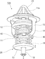
- the thermostat device 10 includes a thermo element 11 that is an operating body that operates according to a change in temperature of a fluid, and one end side (upper side in the drawing) of the thermo element 11 has a substantially umbrella shape.
- the first valve body 12 exhibiting the above is provided, and the second valve having a substantially plate shape at the tip end (lower end side in the figure) of the valve shaft (described later) extending to the other end side (lower side in the figure)
- a body 13 is provided.
- a coil spring 14 that is an urging means for urging the first valve body 12 to the valve closing position and a frame 15 that also serves as a spring retainer are provided in the central portion of the thermoelement 11 in the axial direction. It has been.
- the frame 15 is latched by a support leg on the valve housing side which is a fixing portion to be described later, thereby urging the first valve body 12 in the valve closing direction via the coil spring 14 and the thermo element.
- 11 is a member that slidably holds 11.
- the thermo-element 11 includes a temperature sensing part that encloses a thermal expansion body such as wax that senses the temperature of the fluid and expands and contracts, and the piston rod 11a protrudes forward and backward from the tip (upper end) of the temperature sensing part. ing.
- a thermal expansion body such as wax that senses the temperature of the fluid and expands and contracts
- reference numeral 20 denotes a housing which forms a passage through which coolant from a radiator, which is a fluid inlet / outlet, flows and communicates with an engine inlet portion, and which accommodates and arranges the thermostat device 10 therein.
- a thermostat Inside the housing 20 is a thermostat.
- a valve chamber 21 in which the apparatus 10 is disposed is formed, a cooling water passage (first passage) 21A from the radiator is shown in the upper part in the figure, and a cooling water passage (second passage) that goes to the engine on the right side in the figure. ) 21B, a fluid passage 25 from the bypass flow path (third passage) is formed in the lower part of the figure.
- the housing 20 is made into the structure divided
- a valve seat 22 is formed on the inner side of the flange-like portion provided in the middle in the longitudinal direction of the thermostat device 10 so that the first valve body 12 can be seated. And the thermoelement 11 and the frame 15 etc. which hold
- reference numeral 23 in the figure denotes a locking part for locking and holding the tip of the piston rod 11a.
- a second valve body 13 having a substantially plate shape is fitted and assembled to the lower end of a rod portion 18 as a valve shaft extending downward from the thermo element 11 and is engaged by an E ring or the like. It is elastically supported by being stopped and biased by a coil spring 19.
- a fluid passage (communication passage) 25 that is opened and closed by the second valve body 13 is opened below the housing 20, and a valve seat portion 26 is formed on the periphery of the opening.
- the second valve body 13 is structured to be seated on the valve seat portion 26, and functions as a relief valve that is opened and closed according to the cooling water pressure on the bypass flow path side. Is configured to do.
- the second valve body 13 is urged by the bypass valve 28 as a relief valve by the second valve body 13 and the valve seat portion 26.
- the spring load (spring force) of the coil spring 19 is constant regardless of the movement of the thermo element 11 due to the temperature change, and appropriate and reliable opening / closing control according to the fluid pressure difference of the second valve body 13. It is characterized by being able to do.
- the second valve body 13 slidably supported on the lower end side of the rod portion 18 extending below the thermo element 11 of the thermostat device 10;
- the spring load of the coil spring 19 can be always constant in the bypass valve 28 constituted by the coil spring 19 urging in the valve closing direction.
- a spring receiver that latches and holds the proximal end side of the coil spring 19 is provided on the frame 15 side that is a fixed side in the thermostat device 10.
- thermoelement 11 which moves with a temperature change like the case where the bottom part of the thermoelement 11 which is a movable side is utilized as a spring receiver like the conventional structure. Therefore, it is possible to obtain a constant spring load at all times, thereby stabilizing the function as the bypass valve 28 and providing an excellent effect of increasing the degree of freedom in design.
- the coil spring 19 has a constant cylindrical winding diameter so that a constant spring load can always be obtained.
- the present invention is not limited to this winding diameter shape and is always constant. Any structure can be used as long as the spring load can be obtained.
- the valve opening pressure can be increased as compared with the conventional apparatus.
- the “closing effect” in the bypass circuit at low temperatures can be maintained up to a high speed, and since the bypass passage does not communicate with each other, the engine speed warming effect and the heater function effectively and the effect is good. It becomes possible to demonstrate fuel consumption improvement.
- thermo element 11 since the thermo element 11 is also integrated, there is an advantage that the entire apparatus can be reduced in size.
- the holding projection piece 40 is used to hold the outer diameter portion of the proximal end side of the coil spring.
- the present invention is not limited to the structure described in the above-described embodiment, and the shape, structure, etc. of each part constituting the thermostat device 10 and the bypass valve 28 as a sub valve attached thereto are appropriately modified. Needless to say, it can be changed.
- valve element constituting the sub-valve is slidably held at the lower end side of the thermo-element 11 and is maintained in a closed state by a coil spring, and the valve element has a fluid pressure difference that is independent of temperature change. If the thermostat device 10 has such a structure that it can be opened and closed by, for example, it can be applied to exert an effect.
- the spring receiver is configured by the holding protrusion that becomes the spring receiver by pressing the outer diameter portion of the base end portion of the coil spring 19 from the outer peripheral direction, but the present invention is not limited to this. As long as the spring receiver has various shapes and structures, it may be integrated or separated. In short, any spring receiving portion that can hold the base end portion of the coil spring 19 in a required state may be used.
- the design of the thermostat device which is not a conventional seating type is not greatly changed, the shape is not complicated, and the processing of the element case of the conventional seating type thermostat device is unnecessary. It is also possible to use common parts. For example, there is an advantage that a dedicated product such as a bypass rod is not necessary.
- the thermostat device 10 having a valve opening characteristic in which the opening / closing pressure of the bypass valve 28 is changed is independent of the variation of the cooling water temperature (operation of the thermo element 11). Can also be provided.
- the bypass valve 28 opens at a small cooling water pressure in the initial stage of valve opening, and thereafter the valve opening amount is reduced.
- the spring load increases, so that even if the pressure increases, the opening degree can be kept constant, regardless of the operation of the thermoelement 11, and the optimum cooling water pressure can be controlled.
- the larger outer diameter on the base end side of the tapered coil spring.
- the thermostat device 10 is incorporated on the engine inlet side in the engine coolant circuit.
- the present invention is not limited to this, and the thermostat device 10 is incorporated on the engine outlet side.
- an equivalent effect can be obtained.
Abstract
L'invention vise à maintenir une force de ressort constante pour un ressort hélicoïdal qui sollicite une vanne de dérivation dans un dispositif de thermostat, quel que soit le mouvement d'un élément thermique, et, par conséquent, à permettre une commande d'ouverture/fermeture appropriée et fiable. A cet effet, selon l'invention, une vanne de dérivation (28), qui est ouverte/fermée par la différence de pression entre un deuxième passage (21B) et un troisième passage (25), est disposée dans le corps (20) d'un dispositif de thermostat (10) ayant des vannes principales (12, 22) qui commandent l'écoulement entre un premier passage et le deuxième passage. Un second corps de vanne (13) constituant la vanne de dérivation est maintenu selon un mode de coulissement du côté de pointe d'une partie tige (18) disposée d'un seul tenant avec un élément thermique (11), et une partie de réception de ressort (40), qui vient en prise avec le côté d'extrémité de base d'un ressort hélicoïdal (19) qui sollicite ce second corps de vanne, et qui maintient celui-ci, est disposée sur un côté de bâti qui supporte l'élément thermique selon un mode de coulissement.
Applications Claiming Priority (2)
| Application Number | Priority Date | Filing Date | Title |
|---|---|---|---|
| JP2012116724A JP2013241918A (ja) | 2012-05-22 | 2012-05-22 | サーモスタット装置 |
| JP2012-116724 | 2012-05-22 |
Publications (1)
| Publication Number | Publication Date |
|---|---|
| WO2013175809A1 true WO2013175809A1 (fr) | 2013-11-28 |
Family
ID=49623514
Family Applications (1)
| Application Number | Title | Priority Date | Filing Date |
|---|---|---|---|
| PCT/JP2013/051784 WO2013175809A1 (fr) | 2012-05-22 | 2013-01-28 | Dispositif de thermostat |
Country Status (2)
| Country | Link |
|---|---|
| JP (1) | JP2013241918A (fr) |
| WO (1) | WO2013175809A1 (fr) |
Cited By (4)
| Publication number | Priority date | Publication date | Assignee | Title |
|---|---|---|---|---|
| CN105545453A (zh) * | 2016-02-25 | 2016-05-04 | 茹咪娜 | 耐用型节温器 |
| CN106014592A (zh) * | 2016-02-25 | 2016-10-12 | 茹咪娜 | 直通型节温器 |
| WO2017116424A1 (fr) * | 2015-12-30 | 2017-07-06 | Energx Controls, Inc. | Vanne d'équilibrage thermique et système l'utilisant |
| US10036466B2 (en) | 2014-09-05 | 2018-07-31 | Korens Co., Ltd. | Transmission oil bypass assembly |
Families Citing this family (3)
| Publication number | Priority date | Publication date | Assignee | Title |
|---|---|---|---|---|
| JP6257037B2 (ja) * | 2014-04-25 | 2018-01-10 | 日本サーモスタット株式会社 | サーモスタット装置 |
| US20160109891A1 (en) * | 2014-07-03 | 2016-04-21 | Energx Controls, Inc. | Thermal balancing valve and system using the same |
| EP3608570A1 (fr) * | 2017-04-07 | 2020-02-12 | Nok Corporation | Structure de vanne d'ouverture et de fermeture pour dispositif de thermostat |
Citations (5)
| Publication number | Priority date | Publication date | Assignee | Title |
|---|---|---|---|---|
| JPS6141022Y2 (fr) * | 1981-12-29 | 1986-11-21 | ||
| JPH0633762A (ja) * | 1992-07-15 | 1994-02-08 | Toyota Motor Corp | 内燃機関用サーモスタット |
| JPH0988598A (ja) * | 1995-09-27 | 1997-03-31 | Daihatsu Motor Co Ltd | サーモスタット弁 |
| JPH11336548A (ja) * | 1998-05-22 | 1999-12-07 | Fuji Thomson Kk | 自動車エンジン冷媒循環回路制御用熱応動弁 |
| WO2010122832A1 (fr) * | 2009-04-24 | 2010-10-28 | 日本サーモスタット株式会社 | Dispositif de thermostat |
-
2012
- 2012-05-22 JP JP2012116724A patent/JP2013241918A/ja active Pending
-
2013
- 2013-01-28 WO PCT/JP2013/051784 patent/WO2013175809A1/fr active Application Filing
Patent Citations (5)
| Publication number | Priority date | Publication date | Assignee | Title |
|---|---|---|---|---|
| JPS6141022Y2 (fr) * | 1981-12-29 | 1986-11-21 | ||
| JPH0633762A (ja) * | 1992-07-15 | 1994-02-08 | Toyota Motor Corp | 内燃機関用サーモスタット |
| JPH0988598A (ja) * | 1995-09-27 | 1997-03-31 | Daihatsu Motor Co Ltd | サーモスタット弁 |
| JPH11336548A (ja) * | 1998-05-22 | 1999-12-07 | Fuji Thomson Kk | 自動車エンジン冷媒循環回路制御用熱応動弁 |
| WO2010122832A1 (fr) * | 2009-04-24 | 2010-10-28 | 日本サーモスタット株式会社 | Dispositif de thermostat |
Cited By (4)
| Publication number | Priority date | Publication date | Assignee | Title |
|---|---|---|---|---|
| US10036466B2 (en) | 2014-09-05 | 2018-07-31 | Korens Co., Ltd. | Transmission oil bypass assembly |
| WO2017116424A1 (fr) * | 2015-12-30 | 2017-07-06 | Energx Controls, Inc. | Vanne d'équilibrage thermique et système l'utilisant |
| CN105545453A (zh) * | 2016-02-25 | 2016-05-04 | 茹咪娜 | 耐用型节温器 |
| CN106014592A (zh) * | 2016-02-25 | 2016-10-12 | 茹咪娜 | 直通型节温器 |
Also Published As
| Publication number | Publication date |
|---|---|
| JP2013241918A (ja) | 2013-12-05 |
Similar Documents
| Publication | Publication Date | Title |
|---|---|---|
| WO2013175809A1 (fr) | Dispositif de thermostat | |
| US7721974B2 (en) | Thermostat device | |
| JP5164323B2 (ja) | サーモスタット装置 | |
| US20120247582A1 (en) | Temperature Control Valve With Pressure Relief | |
| WO2004090404A1 (fr) | Thermostat | |
| KR102092946B1 (ko) | 유체 제어 밸브 | |
| KR20100043107A (ko) | 차량의 냉각 장치 | |
| JP5424567B2 (ja) | サーモバルブ及び該サーモバルブを備えた熱媒体回路 | |
| WO2018207740A1 (fr) | Dispositif de vanne de régulation d'eau de refroidissement | |
| JP2010121455A (ja) | 熱応動弁装置 | |
| JP5537245B2 (ja) | 冷却液調整弁 | |
| JP6257037B2 (ja) | サーモスタット装置 | |
| JP5114376B2 (ja) | サーモスタット装置 | |
| US20230075049A1 (en) | Cooling water temperature control device | |
| CN113614343B (zh) | 恒温装置 | |
| WO2022176871A1 (fr) | Dispositif thermostat | |
| WO2020060523A2 (fr) | Structure de valve permettant de réduire au minimum la force requise pour la commande d'une valve et ensemble thermostat associé | |
| JP5799530B2 (ja) | 内燃機関の冷却装置 | |
| WO2021066770A1 (fr) | Ensemble thermostat fournissant une température de sortie constante par ajustement du rapport de mélange de manière autonome | |
| CN115053055A (zh) | 阀单元 | |
| JP2004132242A (ja) | エンジン冷却水制御弁 | |
| JP2014163303A (ja) | 水冷式エンジンのサーモスタット装置 | |
| JP2005127361A (ja) | サーモスタット装置 | |
| JP2019085942A (ja) | 弁装置 | |
| JP2004278589A (ja) | 弁機構 |
Legal Events
| Date | Code | Title | Description |
|---|---|---|---|
| 121 | Ep: the epo has been informed by wipo that ep was designated in this application |
Ref document number: 13793601 Country of ref document: EP Kind code of ref document: A1 |
|
| NENP | Non-entry into the national phase |
Ref country code: DE |
|
| 122 | Ep: pct application non-entry in european phase |
Ref document number: 13793601 Country of ref document: EP Kind code of ref document: A1 |