WO2013175809A1 - Thermostat device - Google Patents
Thermostat device Download PDFInfo
- Publication number
- WO2013175809A1 WO2013175809A1 PCT/JP2013/051784 JP2013051784W WO2013175809A1 WO 2013175809 A1 WO2013175809 A1 WO 2013175809A1 JP 2013051784 W JP2013051784 W JP 2013051784W WO 2013175809 A1 WO2013175809 A1 WO 2013175809A1
- Authority
- WO
- WIPO (PCT)
- Prior art keywords
- valve
- thermostat device
- passage
- coil spring
- cooling water
- Prior art date
Links
Images


Classifications
-
- F—MECHANICAL ENGINEERING; LIGHTING; HEATING; WEAPONS; BLASTING
- F01—MACHINES OR ENGINES IN GENERAL; ENGINE PLANTS IN GENERAL; STEAM ENGINES
- F01P—COOLING OF MACHINES OR ENGINES IN GENERAL; COOLING OF INTERNAL-COMBUSTION ENGINES
- F01P7/00—Controlling of coolant flow
- F01P7/14—Controlling of coolant flow the coolant being liquid
- F01P7/16—Controlling of coolant flow the coolant being liquid by thermostatic control
-
- F—MECHANICAL ENGINEERING; LIGHTING; HEATING; WEAPONS; BLASTING
- F16—ENGINEERING ELEMENTS AND UNITS; GENERAL MEASURES FOR PRODUCING AND MAINTAINING EFFECTIVE FUNCTIONING OF MACHINES OR INSTALLATIONS; THERMAL INSULATION IN GENERAL
- F16K—VALVES; TAPS; COCKS; ACTUATING-FLOATS; DEVICES FOR VENTING OR AERATING
- F16K31/00—Actuating devices; Operating means; Releasing devices
- F16K31/002—Actuating devices; Operating means; Releasing devices actuated by temperature variation
Definitions
- the present invention relates to a cooling water circuit for an engine that circulates cooling water for cooling an internal combustion engine (hereinafter referred to as an engine) used for an automobile or the like with a heat exchanger (hereinafter referred to as a radiator).
- the thermostat device as a temperature-sensitive automatic valve used to control the coolant temperature by switching the flow of the engine coolant by operating according to the temperature change of, particularly when the thermostat device is incorporated in the coolant circuit
- the present invention relates to a thermostat device comprising a seating type relief valve that is seated on a valve seat to maintain the valve closed state and opens the valve by a fluid pressure difference regardless of a temperature change.
- a water-cooled cooling system using a radiator is generally used.
- a thermostat device using a thermal expansion body that adjusts the amount of cooling water circulated to the radiator side has been conventionally used so that the temperature of the cooling water introduced into the engine can be controlled.
- the control valve when a fluid control valve such as a thermostat device using the above-described thermal expansion body is interposed in a part of the cooling water passage, for example, the inlet side or the outlet side of the engine, and the cooling water temperature is low, the control valve The cooling water is circulated through the heater circuit for air conditioning inside the vehicle without passing through the radiator. If the cooling water temperature rises, the control valve is opened and the cooling water is circulated through the radiator. The temperature of the cooling water can be controlled to a required state.
- a fluid control valve such as a thermostat device using the above-described thermal expansion body
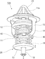
- the thermostat device generally includes a thermo element 1 enclosing a thermal expansion body that operates according to a temperature change of a fluid, and a main body frame 2 as a housing that holds the thermo element 1, On both end sides of the thermo element 1, first and second valve bodies 3, 4 having shapes such as an umbrella shape and a plate shape, for example, are provided, thereby constituting a thermostat device.
- Said 1st valve body 3 functions as a main valve which controls the flow of the cooling water from a radiator to an engine, for example, and the 2nd valve body 4 is the fluid of the cooling water to the engine from a bypass flow path
- This is a bypass valve that controls the pressure and functions as a pressure valve that releases the fluid pressure.
- the second valve body 4 serving as a bypass valve opens against the urging force of the coil spring 5 and the cooling water in the bypass passage flows from the engine outlet toward the water pump. It is possible to prevent the first valve body 3 as the main valve from being forcibly opened.
- thermo element 1 includes a piston 1a as a first valve shaft that moves forward and backward by a thermal expansion body that expands and contracts by sensing the temperature of the fluid, and the movement of the piston 1a is performed on the main body frame 2 side.
- first valve body 3 provided on the outer peripheral portion of the thermo element 1 by the movement in the axial direction of the thermo element 1 that moves relatively in conjunction with this is used as a main valve for the fluid passage. It is configured to appropriately control opening and closing.
- the second valve body 4 functioning as a bypass valve is movably fitted to the distal end side of the rod portion 1b as the second valve shaft provided on the proximal end side of the thermo-element 1 to be locked and supported. And is elastically held in a state of being biased by the coil spring 5. Then, regardless of the movement of the rod portion 1b in the axial direction, the second valve body 4 is seated in the opening of the communication passage 6a provided in the body 6, and the valve closed state is obtained when the thermostat device is incorporated in the body 6.
- the second valve body 4 While maintaining, the second valve body 4 is moved in the valve opening direction against the biasing force of the coil spring 5 due to the pressure difference between the front and rear of the communication passage 6a, and a function as a bypass valve which is a pressure valve can be obtained. It is set as such. That is, the second valve body 4 is configured as a seating type that is seated when the thermostat device is incorporated in the body 6 and maintains the valve closed state (for example, see Patent Document 1).
- the pressure for opening the bypass passage fluctuates according to the cooling water temperature, which causes a problem that it becomes difficult to open as the cooling water becomes hot. For example, it is necessary to relieve the valve opening pressure of the bypass valve (second valve body 4) as the cavitation generation region, that is, as the cooling water becomes hot and the engine speed increases.
- the valve opening pressure varies, if the valve opening pressure at high temperature (P2 in FIG. 4) is set to the relief pressure, the valve opening pressure at low temperature (P1 in FIG. 4) is reduced. It will decline.
- the bypass valve coil when trying to set the best valve opening pressure, the bypass valve coil must be designed to minimize fluctuations in the bypass valve opening pressure when the coolant temperature is high or low. There were also problems such as the design of the spring 5 becoming difficult.
- the coil spring 5 for the bypass valve is tapered depending on the valve diameter matched to the size of the bypass passage 6a and the bottom diameter of the thermo element 1 ( Therefore, when processing and assembling, it takes man-hours to manage the directionality of the coil spring and prevent misassembly, and this increases costs.
- the spring constant (load increase rate) is made small in order to suppress the fluctuation of the valve opening pressure of the bypass valve, if it is taken into consideration, the coil can be sufficiently compressed even when the thermo element 1 is lowered.
- the total length and the set length of the spring 5 are increased, and the entire length of the thermostat is increased, resulting in an increase in size.
- the processing man-hour for fitting the coil spring 5 for a bypass valve to the bottom part (case) of the thermoelement 1 is also required.
- the present invention has been made in view of such circumstances, and is a thermostat device mainly provided at an engine inlet, in which a bypass passage is closed by a bypass valve as a sub valve, and a pressure flowing through the bypass passage is predetermined.
- a thermostat device mainly provided at an engine inlet, in which a bypass passage is closed by a bypass valve as a sub valve, and a pressure flowing through the bypass passage is predetermined.
- the spring force of the coil spring that urges the valve is made constant regardless of the movement of the thermo element, enabling appropriate and reliable opening and closing control
- the purpose is to obtain a thermostat device.
- a thermostat device in a cooling water circuit of an automobile engine, and the flow of cooling water between first and second passages is provided.
- a thermostat device comprising a main valve to be controlled, a thermo element that is disposed in the first passage and that drives and controls the main valve according to a cooling water temperature, and a frame having a holding portion that slidably holds the thermo element.
- the body in which the thermostat device is incorporated includes a third passage, and the second passage and the third passage when the coolant pressure in the coolant circuit becomes equal to or higher than a predetermined pressure.
- a second valve body that opens the communication passage that communicates with each other, and when the thermostat device is incorporated in the body 6, the second valve body is biased in a direction to close the communication passage.
- a coil spring is provided, and one end of the coil spring is locked and held by the second valve body, and the other end is locked and held by a spring receiver provided integrally (integrally or separately) with a part of the frame. It is characterized by comprising.
- the thermostat device according to the present invention (invention according to claim 2) is characterized in that, in claim 1, the spring receiver of the frame is constituted by a holding protrusion for holding the outer diameter portion of the coil spring. To do.
- the thermostat device according to the present invention is the thermostat device according to claim 1 or 2, wherein the second valve body is slidable to a tip end side of a rod portion provided integrally with the thermo element.
- the communication path formed in the body is closed by being held and biased toward the tip of the rod portion by the coil spring.
- the second valve body constituting the bypass valve is slidably held at the tip end side of the rod portion provided integrally with the thermo element, and the second valve Since the spring receiver that holds and holds the base end side of the coil spring that urges the body is provided on the frame side that holds the thermoelement slidably, the following is provided despite the simple configuration. There are various excellent effects described below.
- the spring load (spring force) of the coil spring that urges the seating-type bypass valve provided as a sub-valve in this type of thermostat device is independent of the movement associated with the temperature condition of the thermo element.
- the second valve body can always be urged with a required spring load, so that the second valve body can be stabilized in a required state by a pressure difference between the first and third passages. It can be opened and closed.
- the valve opening pressure fluctuation of the bypass valve can be eliminated and the set pressure can be set in a required state, so that the operation performance is improved and the workability of each part and the flexibility of design of the spring are improved.
- there are various excellent effects such as reduction of the processing cost as described above, improvement of assemblability, and miniaturization.
- FIG. 5 is an operation explanatory diagram when the main valve (first valve body) is in an open state and the sub valve (second valve body) is slightly opened in the thermostat device according to FIG. 1.
- a seating type bypass valve that is a thermostat device mainly provided at the engine inlet and closes the bypass passage by a bypass valve, which is a sub valve, and opens when the pressure flowing through the bypass passage exceeds a predetermined value
- the spring load (spring force) of the coil spring that urges the coil spring is made constant regardless of the movement of the thermo element (that is, the temperature of the cooling water), thereby enabling appropriate and reliable opening / closing control.
- a reference numeral 10 indicates a thermostat device that is a temperature-sensitive automatic valve.
- a thermostat device that is a temperature-sensitive automatic valve.
- a radiator-side cooling water channel and an engine outlet section In order to control the temperature of the cooling water reaching the engine inlet by selectively switching the flow of the cooling water in the fluid flow path formed by these passages attached to the intersection with the bypass flow path from the side It is used for.
- the thermostat device 10 includes a thermo element 11 that is an operating body that operates according to a change in temperature of a fluid, and one end side (upper side in the drawing) of the thermo element 11 has a substantially umbrella shape.
- the first valve body 12 exhibiting the above is provided, and the second valve having a substantially plate shape at the tip end (lower end side in the figure) of the valve shaft (described later) extending to the other end side (lower side in the figure)
- a body 13 is provided.
- a coil spring 14 that is an urging means for urging the first valve body 12 to the valve closing position and a frame 15 that also serves as a spring retainer are provided in the central portion of the thermoelement 11 in the axial direction. It has been.
- the frame 15 is latched by a support leg on the valve housing side which is a fixing portion to be described later, thereby urging the first valve body 12 in the valve closing direction via the coil spring 14 and the thermo element.
- 11 is a member that slidably holds 11.
- the thermo-element 11 includes a temperature sensing part that encloses a thermal expansion body such as wax that senses the temperature of the fluid and expands and contracts, and the piston rod 11a protrudes forward and backward from the tip (upper end) of the temperature sensing part. ing.
- a thermal expansion body such as wax that senses the temperature of the fluid and expands and contracts
- reference numeral 20 denotes a housing which forms a passage through which coolant from a radiator, which is a fluid inlet / outlet, flows and communicates with an engine inlet portion, and which accommodates and arranges the thermostat device 10 therein.
- a thermostat Inside the housing 20 is a thermostat.
- a valve chamber 21 in which the apparatus 10 is disposed is formed, a cooling water passage (first passage) 21A from the radiator is shown in the upper part in the figure, and a cooling water passage (second passage) that goes to the engine on the right side in the figure. ) 21B, a fluid passage 25 from the bypass flow path (third passage) is formed in the lower part of the figure.
- the housing 20 is made into the structure divided
- a valve seat 22 is formed on the inner side of the flange-like portion provided in the middle in the longitudinal direction of the thermostat device 10 so that the first valve body 12 can be seated. And the thermoelement 11 and the frame 15 etc. which hold
- reference numeral 23 in the figure denotes a locking part for locking and holding the tip of the piston rod 11a.
- a second valve body 13 having a substantially plate shape is fitted and assembled to the lower end of a rod portion 18 as a valve shaft extending downward from the thermo element 11 and is engaged by an E ring or the like. It is elastically supported by being stopped and biased by a coil spring 19.
- a fluid passage (communication passage) 25 that is opened and closed by the second valve body 13 is opened below the housing 20, and a valve seat portion 26 is formed on the periphery of the opening.
- the second valve body 13 is structured to be seated on the valve seat portion 26, and functions as a relief valve that is opened and closed according to the cooling water pressure on the bypass flow path side. Is configured to do.
- the second valve body 13 is urged by the bypass valve 28 as a relief valve by the second valve body 13 and the valve seat portion 26.
- the spring load (spring force) of the coil spring 19 is constant regardless of the movement of the thermo element 11 due to the temperature change, and appropriate and reliable opening / closing control according to the fluid pressure difference of the second valve body 13. It is characterized by being able to do.
- the second valve body 13 slidably supported on the lower end side of the rod portion 18 extending below the thermo element 11 of the thermostat device 10;
- the spring load of the coil spring 19 can be always constant in the bypass valve 28 constituted by the coil spring 19 urging in the valve closing direction.
- a spring receiver that latches and holds the proximal end side of the coil spring 19 is provided on the frame 15 side that is a fixed side in the thermostat device 10.
- thermoelement 11 which moves with a temperature change like the case where the bottom part of the thermoelement 11 which is a movable side is utilized as a spring receiver like the conventional structure. Therefore, it is possible to obtain a constant spring load at all times, thereby stabilizing the function as the bypass valve 28 and providing an excellent effect of increasing the degree of freedom in design.
- the coil spring 19 has a constant cylindrical winding diameter so that a constant spring load can always be obtained.
- the present invention is not limited to this winding diameter shape and is always constant. Any structure can be used as long as the spring load can be obtained.
- the valve opening pressure can be increased as compared with the conventional apparatus.
- the “closing effect” in the bypass circuit at low temperatures can be maintained up to a high speed, and since the bypass passage does not communicate with each other, the engine speed warming effect and the heater function effectively and the effect is good. It becomes possible to demonstrate fuel consumption improvement.
- thermo element 11 since the thermo element 11 is also integrated, there is an advantage that the entire apparatus can be reduced in size.
- the holding projection piece 40 is used to hold the outer diameter portion of the proximal end side of the coil spring.
- the present invention is not limited to the structure described in the above-described embodiment, and the shape, structure, etc. of each part constituting the thermostat device 10 and the bypass valve 28 as a sub valve attached thereto are appropriately modified. Needless to say, it can be changed.
- valve element constituting the sub-valve is slidably held at the lower end side of the thermo-element 11 and is maintained in a closed state by a coil spring, and the valve element has a fluid pressure difference that is independent of temperature change. If the thermostat device 10 has such a structure that it can be opened and closed by, for example, it can be applied to exert an effect.
- the spring receiver is configured by the holding protrusion that becomes the spring receiver by pressing the outer diameter portion of the base end portion of the coil spring 19 from the outer peripheral direction, but the present invention is not limited to this. As long as the spring receiver has various shapes and structures, it may be integrated or separated. In short, any spring receiving portion that can hold the base end portion of the coil spring 19 in a required state may be used.
- the design of the thermostat device which is not a conventional seating type is not greatly changed, the shape is not complicated, and the processing of the element case of the conventional seating type thermostat device is unnecessary. It is also possible to use common parts. For example, there is an advantage that a dedicated product such as a bypass rod is not necessary.
- the thermostat device 10 having a valve opening characteristic in which the opening / closing pressure of the bypass valve 28 is changed is independent of the variation of the cooling water temperature (operation of the thermo element 11). Can also be provided.
- the bypass valve 28 opens at a small cooling water pressure in the initial stage of valve opening, and thereafter the valve opening amount is reduced.
- the spring load increases, so that even if the pressure increases, the opening degree can be kept constant, regardless of the operation of the thermoelement 11, and the optimum cooling water pressure can be controlled.
- the larger outer diameter on the base end side of the tapered coil spring.
- the thermostat device 10 is incorporated on the engine inlet side in the engine coolant circuit.
- the present invention is not limited to this, and the thermostat device 10 is incorporated on the engine outlet side.
- an equivalent effect can be obtained.
Abstract
[Problem] To maintain a constant spring force for a coil spring that biases a bypass valve in a thermostat device, regardless of the movement of a thermo element, and thus to enable suitable and reliable opening/closing control.
[Solution] A bypass valve (28), which is opened/closed by the pressure difference between a second passage (21B) and a third passage (25), is provided in the body (20) of a thermostat device (10) having main valves (12, 22) that control the flow between a first passage and the second passage. A second valve body (13) forming the bypass valve is held in a slidable manner at the tip side of a rod part (18) provided integrally with a thermo element (11), and a spring-receiving part (40), which engages and holds the base-end side of a coil spring (19) that biases this second valve body, is provided on a frame side that holds the thermo element in a slidable manner.
Description
本発明は、例えば自動車等に使用される内燃機関(以下、エンジンという)を冷却する冷却水を、熱交換器(以下、ラジエータという)との間で循環させるエンジンの冷却水回路において、冷却水の温度変化により作動することでエンジン冷却水の流れを切換えて冷却水温度を制御するために用いられる温度感知式自動弁としてのサーモスタット装置に関し、特にサーモスタット装置を冷却水回路に組み込んだ際において、弁座に着座して弁閉状態を維持するとともに、温度変化とは無関係に流体圧力差で弁開する着座タイプのリリーフバルブを備えてなるサーモスタット装置に関する。
The present invention relates to a cooling water circuit for an engine that circulates cooling water for cooling an internal combustion engine (hereinafter referred to as an engine) used for an automobile or the like with a heat exchanger (hereinafter referred to as a radiator). The thermostat device as a temperature-sensitive automatic valve used to control the coolant temperature by switching the flow of the engine coolant by operating according to the temperature change of, particularly when the thermostat device is incorporated in the coolant circuit, The present invention relates to a thermostat device comprising a seating type relief valve that is seated on a valve seat to maintain the valve closed state and opens the valve by a fluid pressure difference regardless of a temperature change.
従来この種の流体制御バルブとしては、例えば特許文献1に記載されているように、自動車用エンジンの冷却装置に用いられるサーモスタット装置が知られている。
Conventionally, as this type of fluid control valve, as described in Patent Document 1, for example, a thermostat device used for a cooling device for an automobile engine is known.
これを簡単に説明すると、自動車用エンジンにおいて、これを冷却するためには、一般にはラジエータを用いた水冷式の冷却システムが使用されている。この種の冷却システムにおいては、エンジンに導入する冷却水の温度を制御できるように、ラジエータ側に循環させる冷却水量を調節する熱膨張体を用いたサーモスタット装置などが従来から使用されている。
Briefly explaining this, in order to cool an automobile engine, a water-cooled cooling system using a radiator is generally used. In this type of cooling system, a thermostat device using a thermal expansion body that adjusts the amount of cooling water circulated to the radiator side has been conventionally used so that the temperature of the cooling water introduced into the engine can be controlled.
即ち、上記の熱膨張体を用いたサーモスタット装置などの流体制御バルブを、冷却水通路の一部、例えばエンジンの入口側または出口側に介装し、冷却水温度が低い場合に、該制御バルブを閉じて冷却水をラジエータを経由せず車内空調用のヒータ回路を介して循環させ、また冷却水温度が高くなった場合は、制御バルブを開いて冷却水がラジエータを通して循環させることで、エンジン冷却水の温度を所要の状態に制御することができるものである。
That is, when a fluid control valve such as a thermostat device using the above-described thermal expansion body is interposed in a part of the cooling water passage, for example, the inlet side or the outlet side of the engine, and the cooling water temperature is low, the control valve The cooling water is circulated through the heater circuit for air conditioning inside the vehicle without passing through the radiator.If the cooling water temperature rises, the control valve is opened and the cooling water is circulated through the radiator. The temperature of the cooling water can be controlled to a required state.
上記のサーモスタット装置は、一般には、図5から明らかなように、流体の温度変化により作動する熱膨張体を封入したサーモエレメント1と、これを保持するハウジングとしての本体フレーム2とを備え、前記サーモエレメント1の両端側には、例えば傘状、板状等といった形状をもつ第1、第2の弁体3,4が設けられ、これによりサーモスタット装置を構成している。
As is apparent from FIG. 5, the thermostat device generally includes a thermo element 1 enclosing a thermal expansion body that operates according to a temperature change of a fluid, and a main body frame 2 as a housing that holds the thermo element 1, On both end sides of the thermo element 1, first and second valve bodies 3, 4 having shapes such as an umbrella shape and a plate shape, for example, are provided, thereby constituting a thermostat device.
上記の第1の弁体3は、例えばラジエータからエンジンへの冷却水の流れを制御するメインバルブとして機能し、また第2の弁体4は、バイバス流路からのエンジンへの冷却水の流体圧力を制御するバイパスバルブとなるものであって、流体圧力を開放する圧力バルブとして機能するような構成となっている。それにより、所定の圧力以下では、積極的に前記ヒータ回路へ冷却水を循環させている。
Said 1st valve body 3 functions as a main valve which controls the flow of the cooling water from a radiator to an engine, for example, and the 2nd valve body 4 is the fluid of the cooling water to the engine from a bypass flow path This is a bypass valve that controls the pressure and functions as a pressure valve that releases the fluid pressure. Thereby, the cooling water is actively circulated to the heater circuit below a predetermined pressure.
すなわち、ヒータ回路の流通抵抗が多少大きくても、冷却水はバイパス通路を通ることなく、ヒータ回路を通ることになり、ヒータが効果的に機能してその効きが早くなる。しかも、ヒータ回路の流通抵抗が高く、かつ冷却水を流通させるウォータポンプの回転数が高くなって、ウォータポンプに接続されているエンジン出口側の圧力が低くなり、バイパス回路との差圧が所定以上になると、バイパスバルブとなる第2の弁体4はコイルばね5の付勢力に抗して開いてバイパス通路の冷却水がエンジン出口からウォータポンプに向けて流れるため、ウォータポンプのキャビテーションの発生を防止し、メインバルブである第1の弁体3が強制的に開弁されるのを防止することができるものである。
That is, even if the flow resistance of the heater circuit is somewhat large, the cooling water passes through the heater circuit without passing through the bypass passage, so that the heater functions effectively and its effectiveness is accelerated. In addition, the flow resistance of the heater circuit is high, and the rotation speed of the water pump through which the cooling water flows is high, the pressure on the engine outlet side connected to the water pump is low, and the differential pressure from the bypass circuit is predetermined. When the above is reached, the second valve body 4 serving as a bypass valve opens against the urging force of the coil spring 5 and the cooling water in the bypass passage flows from the engine outlet toward the water pump. It is possible to prevent the first valve body 3 as the main valve from being forcibly opened.
ここで、前記サーモエレメント1は、流体の温度を感知して膨張、収縮する熱膨張体により進退動作する第1の弁軸としてのピストン1aを備え、このピストン1aの動きが本体フレーム2側で拘束されることにより、これに連動して相対的に移動するサーモエレメント1の軸線方向の動きにより該サーモエレメント1の外周部に設けられている第1の弁体3がメインバルブとして流体通路を適宜開閉制御するように構成されている。
Here, the thermo element 1 includes a piston 1a as a first valve shaft that moves forward and backward by a thermal expansion body that expands and contracts by sensing the temperature of the fluid, and the movement of the piston 1a is performed on the main body frame 2 side. By being restrained, the first valve body 3 provided on the outer peripheral portion of the thermo element 1 by the movement in the axial direction of the thermo element 1 that moves relatively in conjunction with this is used as a main valve for the fluid passage. It is configured to appropriately control opening and closing.
一方、バイパスバルブとして機能する第2の弁体4は、前記サーモエレメント1の基端側に設けた第2の弁軸としてのロッド部1bの先端側に移動可能に嵌装して係止支持され、かつコイルばね5により付勢された状態で弾性保持されている。そして、ロッド部1bの軸線方向の動きとは無関係に、第2の弁体4をボディ6に設けた連通路6aの開口に着座させ、サーモスタット装置をボディ6に組み込んだ際において弁閉状態を維持するとともに、前記連通路6aの前後の圧力差により第2の弁体4をコイルばね5の付勢力に抗して弁開方向に移動させ、圧力バルブであるバイパスバルブとしての機能を得られるような構成とされている。すなわち、この第2の弁体4は、サーモスタット装置をボディ6に組み込んだ際において着座して弁閉状態を維持する着座タイプとして構成されている(例えば、特許文献1参照)。
On the other hand, the second valve body 4 functioning as a bypass valve is movably fitted to the distal end side of the rod portion 1b as the second valve shaft provided on the proximal end side of the thermo-element 1 to be locked and supported. And is elastically held in a state of being biased by the coil spring 5. Then, regardless of the movement of the rod portion 1b in the axial direction, the second valve body 4 is seated in the opening of the communication passage 6a provided in the body 6, and the valve closed state is obtained when the thermostat device is incorporated in the body 6. While maintaining, the second valve body 4 is moved in the valve opening direction against the biasing force of the coil spring 5 due to the pressure difference between the front and rear of the communication passage 6a, and a function as a bypass valve which is a pressure valve can be obtained. It is set as such. That is, the second valve body 4 is configured as a seating type that is seated when the thermostat device is incorporated in the body 6 and maintains the valve closed state (for example, see Patent Document 1).
しかし、上述した特許文献1によるサーモスタットバルブでは、サーモエレメント1の底部にバイパスバルブ用のコイルばね5が係合して設けられているため、冷却水温度に感応してサーモエレメント1が下方に移動したときに、バイパス通路6aの開口に着座しているバイパスバルブは移動しないことから、バイパスバルブに加わるバイパスバルブ用のコイルばね5のばね荷重(ばね力)が変動して上昇することになる。
However, in the thermostat valve according to Patent Document 1 described above, since the coil spring 5 for the bypass valve is engaged with the bottom of the thermo element 1, the thermo element 1 moves downward in response to the cooling water temperature. In this case, since the bypass valve seated in the opening of the bypass passage 6a does not move, the spring load (spring force) of the coil spring 5 for the bypass valve applied to the bypass valve fluctuates and rises.
すなわち、上述した構造によれば、冷却水温に応じてバイパス通路を開ける圧力が変動してしまい、冷却水が高温になるにつれて開きにくくなってしまうという問題を生じる。例えば、キャビテーションの発生領域、つまり冷却水が高温で、かつエンジンが高回転になるにつれて、バイパスバルブ(第2の弁体4)の開弁圧力をリリーフする必要がある。しかし、この従来構造によれば、開弁圧力に変動があるため、高温時の開弁圧力(図4中P2)をリリーフ圧力に設定すると、低温時の開弁圧(図4中P1)が低下してしまう。
That is, according to the above-described structure, the pressure for opening the bypass passage fluctuates according to the cooling water temperature, which causes a problem that it becomes difficult to open as the cooling water becomes hot. For example, it is necessary to relieve the valve opening pressure of the bypass valve (second valve body 4) as the cavitation generation region, that is, as the cooling water becomes hot and the engine speed increases. However, according to this conventional structure, since the valve opening pressure varies, if the valve opening pressure at high temperature (P2 in FIG. 4) is set to the relief pressure, the valve opening pressure at low temperature (P1 in FIG. 4) is reduced. It will decline.
さらに、最良のバイパスバルブの開弁圧力を設定しようとした場合、冷却水が高温・低温時でバイパスバルブ開弁圧力が変動することを極力小さくして設計しなければならないため、バイパスバルブ用コイルばね5の設計が困難になる等の問題もであった。
Furthermore, when trying to set the best valve opening pressure, the bypass valve coil must be designed to minimize fluctuations in the bypass valve opening pressure when the coolant temperature is high or low. There were also problems such as the design of the spring 5 becoming difficult.
また、バイパスバルブが可能な限り安定して作動させるために、バイパス通路6aの大きさに合わせたバルブ径とサーモエレメント1の底部径に依存して、バイパスバルブ用のコイルばね5をテーパ形状(側面視円錐台形状)で形成しているため、その加工および組付ける際に、コイルばねの方向性を管理し誤組を防止する等に工数がかかりコストアップの要因となっていた。
In order to operate the bypass valve as stably as possible, the coil spring 5 for the bypass valve is tapered depending on the valve diameter matched to the size of the bypass passage 6a and the bottom diameter of the thermo element 1 ( Therefore, when processing and assembling, it takes man-hours to manage the directionality of the coil spring and prevent misassembly, and this increases costs.
さらに、バイパスバルブ開弁圧の前記変動を抑えるためにばね定数(荷重上昇率)を小さくしているため、それを考慮し、サーモエレメント1が下降した際にも充分に圧縮できるようにするとコイルばね5の全長およびセット長が長くなり、ひいてはサーモスタット全長も長くなってしまい大型化する等の問題もあった。
また、その他にも、サーモエレメント1の底部(ケース)にバイパスバルブ用のコイルばね5を嵌合させるための加工工数も必要となるものであった。 Furthermore, since the spring constant (load increase rate) is made small in order to suppress the fluctuation of the valve opening pressure of the bypass valve, if it is taken into consideration, the coil can be sufficiently compressed even when the thermo element 1 is lowered. There is a problem that the total length and the set length of thespring 5 are increased, and the entire length of the thermostat is increased, resulting in an increase in size.
In addition, the processing man-hour for fitting thecoil spring 5 for a bypass valve to the bottom part (case) of the thermoelement 1 is also required.
また、その他にも、サーモエレメント1の底部(ケース)にバイパスバルブ用のコイルばね5を嵌合させるための加工工数も必要となるものであった。 Furthermore, since the spring constant (load increase rate) is made small in order to suppress the fluctuation of the valve opening pressure of the bypass valve, if it is taken into consideration, the coil can be sufficiently compressed even when the thermo element 1 is lowered. There is a problem that the total length and the set length of the
In addition, the processing man-hour for fitting the
本発明はこのような事情に鑑みてなされたものであり、主にエンジン入口部に設けられるサーモスタット装置であって、サブバルブであるバイパスバルブでバイパス通路を閉弁し、バイパス通路を流れる圧力が所定の値を超えた場合に開弁する着座式のバイパスバルブにおいて、これを付勢するコイルばねのばね力を、サーモエレメントの動きとは無関係に一定にし、適切かつ確実な開閉制御を可能とするサーモスタット装置を得ることを目的とする。
The present invention has been made in view of such circumstances, and is a thermostat device mainly provided at an engine inlet, in which a bypass passage is closed by a bypass valve as a sub valve, and a pressure flowing through the bypass passage is predetermined. In a seating-type bypass valve that opens when the value exceeds this value, the spring force of the coil spring that urges the valve is made constant regardless of the movement of the thermo element, enabling appropriate and reliable opening and closing control The purpose is to obtain a thermostat device.
このような目的に応えるために本発明(請求項1記載の発明)に係るサーモスタット装置は、自動車用エンジンの冷却水回路中に設けられ第1、第2の通路間での冷却水の流れを制御するメインバルブと前記第1の通路内に配置され冷却水温度に従って前記メインバルブを駆動制御するサーモエレメントと前記サーモエレメントを摺動自在に保持する保持部を有するフレームとを備えたサーモスタット装置であって、前記サーモスタット装置が組み込まれたボディは第3の通路を備えるとともに、前記冷却水回路内での冷却水圧力が所定圧以上になったときに該第2の通路と第3の通路とを連通させる連通路を開弁する第2弁体と、サーモスタット装置をボディ6に組み込んだ際においてこの第2弁体を前記連通路を閉弁する方向に付勢するコイルばねを備え、このコイルばねの一端を前記第2弁体に係止保持させるとともに、他端を前記フレームの一部に一体的(一体または別体)に設けたばね受けに係止保持させるように構成したことを特徴とする。
In order to meet such a purpose, a thermostat device according to the present invention (the invention described in claim 1) is provided in a cooling water circuit of an automobile engine, and the flow of cooling water between first and second passages is provided. A thermostat device comprising a main valve to be controlled, a thermo element that is disposed in the first passage and that drives and controls the main valve according to a cooling water temperature, and a frame having a holding portion that slidably holds the thermo element. The body in which the thermostat device is incorporated includes a third passage, and the second passage and the third passage when the coolant pressure in the coolant circuit becomes equal to or higher than a predetermined pressure. A second valve body that opens the communication passage that communicates with each other, and when the thermostat device is incorporated in the body 6, the second valve body is biased in a direction to close the communication passage. A coil spring is provided, and one end of the coil spring is locked and held by the second valve body, and the other end is locked and held by a spring receiver provided integrally (integrally or separately) with a part of the frame. It is characterized by comprising.
本発明(請求項2記載の発明)に係るサーモスタット装置は、請求項1において、前記フレームのばね受けは、コイルばねの外径部を保持する保持用突片によって構成されていることを特徴とする。
The thermostat device according to the present invention (invention according to claim 2) is characterized in that, in claim 1, the spring receiver of the frame is constituted by a holding protrusion for holding the outer diameter portion of the coil spring. To do.
本発明(請求項3記載の発明)に係るサーモスタット装置は、請求項1または請求項2において、前記第2弁体は前記サーモエレメントに一体的に設けたロッド部の先端側に摺動自在に保持され、前記コイルばねによりロッド部先端側に付勢されることにより、前記ボディに形成されている連通路を閉塞するように構成されていることを特徴とする。
The thermostat device according to the present invention (the invention according to claim 3) is the thermostat device according to claim 1 or 2, wherein the second valve body is slidable to a tip end side of a rod portion provided integrally with the thermo element. The communication path formed in the body is closed by being held and biased toward the tip of the rod portion by the coil spring.
以上説明したように本発明に係るサーモスタット装置によれば、バイパスバルブを構成する第2弁体をサーモエレメントに一体的に設けたロッド部先端側に摺動自在に保持させるとともに、この第2弁体を付勢するコイルばねの基端側を係止保持するばね受けを、サーモエレメントを摺動自在に保持するフレーム側に設けるように構成したので、簡単な構成であるにもかかわらず、以下に述べる種々優れた効果を奏する。
As described above, according to the thermostat device of the present invention, the second valve body constituting the bypass valve is slidably held at the tip end side of the rod portion provided integrally with the thermo element, and the second valve Since the spring receiver that holds and holds the base end side of the coil spring that urges the body is provided on the frame side that holds the thermoelement slidably, the following is provided despite the simple configuration. There are various excellent effects described below.
すなわち、本発明によれば、この種のサーモスタット装置においてサブバルブとして設けられる着座タイプのバイパスバルブを付勢するコイルばねのばね荷重(ばね力)を、サーモエレメントの温度条件に伴う動きとは無関係に一定にし、常に所要のばね荷重での第2弁体を付勢することができ、これにより該第2弁体を第1、第3の通路間での圧力差により所要の状態で安定して開閉動作させることができる。
That is, according to the present invention, the spring load (spring force) of the coil spring that urges the seating-type bypass valve provided as a sub-valve in this type of thermostat device is independent of the movement associated with the temperature condition of the thermo element. The second valve body can always be urged with a required spring load, so that the second valve body can be stabilized in a required state by a pressure difference between the first and third passages. It can be opened and closed.
したがって、本発明によれば、バイパスバルブの開弁圧力変動をなくし、その設定圧を所要の状態で設定できることから、動作性能を向上させるとともに、各部の加工性、さらにばねの設計自由度を向上させ、前記したような加工コストを低減、組付け性向上ならびに小型化できる等の種々優れた効果がある。
Therefore, according to the present invention, the valve opening pressure fluctuation of the bypass valve can be eliminated and the set pressure can be set in a required state, so that the operation performance is improved and the workability of each part and the flexibility of design of the spring are improved. Thus, there are various excellent effects such as reduction of the processing cost as described above, improvement of assemblability, and miniaturization.
主にエンジン入口部に設けられるサーモスタット装置であって、サブバルブであるバイパスバルブでバイパス通路を閉弁し、バイパス通路を流れる圧力が所定の値を超えた場合に開弁する着座タイプのバイパスバルブにおいて、これを付勢するコイルばねのばね荷重(ばね力)を、サーモエレメントの動き(つまり、冷却水の温度)とは無関係に一定にし、適切かつ確実な開閉制御を可能とする。
In a seating type bypass valve that is a thermostat device mainly provided at the engine inlet and closes the bypass passage by a bypass valve, which is a sub valve, and opens when the pressure flowing through the bypass passage exceeds a predetermined value The spring load (spring force) of the coil spring that urges the coil spring is made constant regardless of the movement of the thermo element (that is, the temperature of the cooling water), thereby enabling appropriate and reliable opening / closing control.
図1ないし図3は本発明に係るサーモスタット装置の一実施例を示す。
これらの図において、全体を符号10で示すものは、温度感知式自動弁であるサーモスタット装置であり、例えば自動車用エンジンの冷却システム(図示せず)において、ラジエータ側の冷却水路と、エンジン出口部側からのバイパス流路との交差部に付設され、これらの通路によって構成される流体流路での冷却水の流れを選択的に切り換えることにより、エンジン入口部に至る冷却水温度を制御するために用いられている。 1 to 3 show an embodiment of a thermostat device according to the present invention.
In these drawings, areference numeral 10 indicates a thermostat device that is a temperature-sensitive automatic valve. For example, in a cooling system (not shown) for an automobile engine, a radiator-side cooling water channel and an engine outlet section In order to control the temperature of the cooling water reaching the engine inlet by selectively switching the flow of the cooling water in the fluid flow path formed by these passages attached to the intersection with the bypass flow path from the side It is used for.
これらの図において、全体を符号10で示すものは、温度感知式自動弁であるサーモスタット装置であり、例えば自動車用エンジンの冷却システム(図示せず)において、ラジエータ側の冷却水路と、エンジン出口部側からのバイパス流路との交差部に付設され、これらの通路によって構成される流体流路での冷却水の流れを選択的に切り換えることにより、エンジン入口部に至る冷却水温度を制御するために用いられている。 1 to 3 show an embodiment of a thermostat device according to the present invention.
In these drawings, a
前記サーモスタット装置10は、図1、図2に示すように、流体の温度変化により作動する作動体であるサーモエレメント11を備え、このサーモエレメント11の一端側(図中上側)にはほぼ傘状を呈する第1の弁体12を設けるとともに、他端側(図中下側)に延びた弁軸(後述する)の先端部(図中下端側)にはほぼ板状を呈する第2の弁体13を設けている。また、サーモエレメント11の軸線方向の中央部分には、第1の弁体12を弁閉位置に付勢する付勢手段であるコイルばね14と、そのばね押さえを兼ねるフレーム15が嵌挿して設けられている。このフレーム15は、後述する固定部であるバルブハウジング側の支持脚に係止されることにより、第1の弁体12をコイルばね14を介して弁閉方向に付勢するとともに、該サーモエレメント11を摺動自在に保持する部材である。
As shown in FIGS. 1 and 2, the thermostat device 10 includes a thermo element 11 that is an operating body that operates according to a change in temperature of a fluid, and one end side (upper side in the drawing) of the thermo element 11 has a substantially umbrella shape. The first valve body 12 exhibiting the above is provided, and the second valve having a substantially plate shape at the tip end (lower end side in the figure) of the valve shaft (described later) extending to the other end side (lower side in the figure) A body 13 is provided. Further, a coil spring 14 that is an urging means for urging the first valve body 12 to the valve closing position and a frame 15 that also serves as a spring retainer are provided in the central portion of the thermoelement 11 in the axial direction. It has been. The frame 15 is latched by a support leg on the valve housing side which is a fixing portion to be described later, thereby urging the first valve body 12 in the valve closing direction via the coil spring 14 and the thermo element. 11 is a member that slidably holds 11.
前記サーモエレメント11は、流体の温度を感知して膨張収縮するワックス等の熱膨張体を内封した温度感知部を備え、この温度感知部の先端(上端)からピストンロッド11aが進退自在に突出している。
The thermo-element 11 includes a temperature sensing part that encloses a thermal expansion body such as wax that senses the temperature of the fluid and expands and contracts, and the piston rod 11a protrudes forward and backward from the tip (upper end) of the temperature sensing part. ing.
図中20は流体出入り口であるラジエータからの冷却水が流入しエンジン入口部に連通する通路を構成するとともに内部に前記サーモスタット装置10を収納配置するハウジングであり、このハウジング20の内部には、サーモスタット装置10を配置する弁室21が形成されるとともに、図中上方にはラジエータからの冷却水通路(第1の通路)21Aが、図中右側にはエンジンに向かう冷却水通路(第2の通路)21Bが、図中下方にはバイパス流路(第3の通路)からの流体通路25が形成されている。なお、ハウジング20は、ここでは上下に分割した構造とされている。
In the figure, reference numeral 20 denotes a housing which forms a passage through which coolant from a radiator, which is a fluid inlet / outlet, flows and communicates with an engine inlet portion, and which accommodates and arranges the thermostat device 10 therein. Inside the housing 20 is a thermostat. A valve chamber 21 in which the apparatus 10 is disposed is formed, a cooling water passage (first passage) 21A from the radiator is shown in the upper part in the figure, and a cooling water passage (second passage) that goes to the engine on the right side in the figure. ) 21B, a fluid passage 25 from the bypass flow path (third passage) is formed in the lower part of the figure. In addition, the housing 20 is made into the structure divided | segmented up and down here.
また、サーモスタット装置10の長手方向の中程に設けたフランジ状部の内側には、前記第1の弁体12が着座可能に対向する弁座22が形成されている。そして、この弁座22に弁体12が着座可能な状態で、サーモエレメント11やこれを摺動自在に保持するフレーム15等が組み込まれている。
Further, a valve seat 22 is formed on the inner side of the flange-like portion provided in the middle in the longitudinal direction of the thermostat device 10 so that the first valve body 12 can be seated. And the thermoelement 11 and the frame 15 etc. which hold | maintain this slidably in the state which can seat the valve body 12 in this valve seat 22 are integrated.
さらに、図中23は前記ピストンロッド11aの先端部を係止保持する係止部であり、図1の状態において、ピストンロッド11aが熱膨張体の熱膨張によって図中上方に突出すると、サーモエレメント11と第1の弁体12が、相対的に図中下方に向かって移動し、第1の弁体12は適宜の弁開状態となり、ラジエータからの冷却水をエンジン側に流通させるように構成されている。
Further, reference numeral 23 in the figure denotes a locking part for locking and holding the tip of the piston rod 11a. When the piston rod 11a protrudes upward in the figure due to thermal expansion of the thermal expansion body in the state of FIG. 11 and the first valve body 12 move relatively downward in the figure, the first valve body 12 is in an appropriate valve open state, and the cooling water from the radiator is circulated to the engine side. Has been.
一方、前記サーモエレメント11から下方に延設された弁軸としてのロッド部18の下端には、ほぼ板状を呈する第2の弁体13が嵌装して組付けられてEリング等で係止され、かつコイルばね19により付勢されることにより弾性支持されている。また、ハウジング20の下方には、第2の弁体13によって開閉される流体通路(連通路)25が開口し、その開口周縁に弁座シート部26が形成されている。
On the other hand, a second valve body 13 having a substantially plate shape is fitted and assembled to the lower end of a rod portion 18 as a valve shaft extending downward from the thermo element 11 and is engaged by an E ring or the like. It is elastically supported by being stopped and biased by a coil spring 19. A fluid passage (communication passage) 25 that is opened and closed by the second valve body 13 is opened below the housing 20, and a valve seat portion 26 is formed on the periphery of the opening.
ここで、この実施例では、第2の弁体13は、上記の弁座シート部26に着座する構造となっており、バイパス流路側での冷却水圧力に応じて開閉されるリリーフバルブとして機能するように構成されている。
Here, in this embodiment, the second valve body 13 is structured to be seated on the valve seat portion 26, and functions as a relief valve that is opened and closed according to the cooling water pressure on the bypass flow path side. Is configured to do.
さて、本発明によれば、以上の構成によるサーモスタット装置10において、第2の弁体13と弁座シート部26とによるリリーフバルブとしてのバイパスバルブ28において、該第2の弁体13を付勢するコイルばね19のばね荷重(ばね力)を、サーモエレメント11の温度変化に伴う移動の如何にかかわらず、一定とし、この第2の弁体13の流体圧力差に伴う適切かつ確実な開閉制御を行えるようにしたところを特徴としている。
Now, according to the present invention, in the thermostat device 10 having the above-described configuration, the second valve body 13 is urged by the bypass valve 28 as a relief valve by the second valve body 13 and the valve seat portion 26. The spring load (spring force) of the coil spring 19 is constant regardless of the movement of the thermo element 11 due to the temperature change, and appropriate and reliable opening / closing control according to the fluid pressure difference of the second valve body 13. It is characterized by being able to do.
これを詳述すると、本発明によれば、前記サーモスタット装置10のサーモエレメント11の下方に延設されているロッド部18の下端側に摺動自在に支持されている第2弁体13と、これをサーモスタット装置をボディ6に組み込んだ際においては閉弁する方向に付勢するコイルばね19とから構成されているバイパスバルブ28において、前記コイルばね19のばね荷重を常に一定とすることができるように、このコイルばね19の基端側を係止保持するばね受けを、サーモスタット装置10における固定側であるフレーム15側に設けたものである。
More specifically, according to the present invention, the second valve body 13 slidably supported on the lower end side of the rod portion 18 extending below the thermo element 11 of the thermostat device 10; When the thermostat device is incorporated in the body 6, the spring load of the coil spring 19 can be always constant in the bypass valve 28 constituted by the coil spring 19 urging in the valve closing direction. As described above, a spring receiver that latches and holds the proximal end side of the coil spring 19 is provided on the frame 15 side that is a fixed side in the thermostat device 10.
このように構成すれば、従来構造のように可動側であるサーモエレメント11の底部をばね受けとして利用する場合のようにばね荷重が、温度変化に伴って移動するサーモエレメント11によって変動するといった事象はなくなり、常に一定のばね荷重を得ることが可能で、これによりバイパスバルブ28としての機能が安定し、設計の自由度が上がるという優れた効果を奏する。
If comprised in this way, the event that a spring load is fluctuate | varied with the thermoelement 11 which moves with a temperature change like the case where the bottom part of the thermoelement 11 which is a movable side is utilized as a spring receiver like the conventional structure. Therefore, it is possible to obtain a constant spring load at all times, thereby stabilizing the function as the bypass valve 28 and providing an excellent effect of increasing the degree of freedom in design.
本実施例では、コイルばね19は、常に一定のばね荷重を得られるように円筒形状の一定の巻き径を有しているが、勿論、本発明はその巻き径形状に限定されず、常に一定のばね荷重が得られるような構造であれば良い。
In this embodiment, the coil spring 19 has a constant cylindrical winding diameter so that a constant spring load can always be obtained. Of course, the present invention is not limited to this winding diameter shape and is always constant. Any structure can be used as long as the spring load can be obtained.
特に、本発明によるサーモスタット装置10によるバイパスバルブ28での開弁圧力が、図4から明らかなように、高温時でも低温時でも変動しない(P1=P2)圧力バルブとなることから、低温時の開弁圧を従来装置に比べて上昇させることができる。そして、これにより、低温時のバイパス回路での「閉止効果」を高回転まで維持できることになり、バイパス通路が連通しないためエンジン速暖効果、また、ヒータが効果的に機能してその効きが良くなる等、燃費向上を発揮させることが可能となる。
In particular, the valve opening pressure of the bypass valve 28 by the thermostat device 10 according to the present invention is a pressure valve that does not fluctuate at both high and low temperatures (P1 = P2), as is apparent from FIG. The valve opening pressure can be increased as compared with the conventional apparatus. As a result, the “closing effect” in the bypass circuit at low temperatures can be maintained up to a high speed, and since the bypass passage does not communicate with each other, the engine speed warming effect and the heater function effectively and the effect is good. It becomes possible to demonstrate fuel consumption improvement.
また、このような構成によれば、サーモエレメント11も一体的であるため、装置全体の小型化が可能であるといった利点もある。
Further, according to such a configuration, since the thermo element 11 is also integrated, there is an advantage that the entire apparatus can be reduced in size.
ここで、この実施例では、フレーム15のばね受けとして、図1ないし図3から明らかなように、コイルばねの基端側の外径部を保持する保持用突片40によって構成している。
Here, in this embodiment, as a spring receiver of the frame 15, as is apparent from FIG. 1 to FIG. 3, the holding projection piece 40 is used to hold the outer diameter portion of the proximal end side of the coil spring.
なお、本発明は上述した実施の形態で説明した構造には限定されず、サーモスタット装置10、さらにこれに付設されているサブバルブとしてのバイパスバルブ28を構成する各部の形状、構造等を適宜変形、変更し得ることはいうまでもない。
The present invention is not limited to the structure described in the above-described embodiment, and the shape, structure, etc. of each part constituting the thermostat device 10 and the bypass valve 28 as a sub valve attached thereto are appropriately modified. Needless to say, it can be changed.
要は、サーモエレメント11の下端側にサブバルブを構成する弁体が摺動自在に保持され、かつコイルばねで弁閉状態に維持されるとともに、該弁体が温度変化とは無関係の流体圧力差等によって開閉動作する等の構造をもつサーモスタット装置10であれば、適用して効果を発揮し得るものである。
In short, the valve element constituting the sub-valve is slidably held at the lower end side of the thermo-element 11 and is maintained in a closed state by a coil spring, and the valve element has a fluid pressure difference that is independent of temperature change. If the thermostat device 10 has such a structure that it can be opened and closed by, for example, it can be applied to exert an effect.
また、上述した実施例では、コイルばね19の基端部外径部を外周方向から押さえ込むことでばね受けとなる保持用突片によってばね受けを構成しているが、本発明はこれに限らず、種々の形状、構造をもつばね受けであれば、一体あるいは別体構成であってもよい。要は、コイルばね19の基端部を所要の状態で押さえることができるばね受け部であればよい。
Further, in the above-described embodiment, the spring receiver is configured by the holding protrusion that becomes the spring receiver by pressing the outer diameter portion of the base end portion of the coil spring 19 from the outer peripheral direction, but the present invention is not limited to this. As long as the spring receiver has various shapes and structures, it may be integrated or separated. In short, any spring receiving portion that can hold the base end portion of the coil spring 19 in a required state may be used.
特に、このような構成によれば、従来の着座タイプでないサーモスタット装置に対し、大きく設計変更することなく、複雑な形状にならず、従来の着座タイプのサーモスタット装置のエレメントケースの加工も不要で、共通部品を使用することも可能となる。例えば、バイパスロッドなど専用品が不要となるという利点を奏することができる。
In particular, according to such a configuration, the design of the thermostat device which is not a conventional seating type is not greatly changed, the shape is not complicated, and the processing of the element case of the conventional seating type thermostat device is unnecessary. It is also possible to use common parts. For example, there is an advantage that a dedicated product such as a bypass rod is not necessary.
さらに、上述した構成によれば、テーパ状、あるいはコイルばねの両端よりも中央部の巻き径が大きい樽状等の巻き径形状が異形であって荷重が一定でなく変動するようなコイルばねも採用することが可能である。このような形状のコイルばねを用いた場合は、冷却水温の変動(サーモエレメント11の作動)とは無関係に、バイパスバルブ28の開閉圧を変化させた開弁特性を持たせたサーモスタット装置10をも提供することができる。例えば、テーパ状のコイルばねを用いそのコイルばねの基端側に外径の小さい方を設けた場合、バイパスバルブ28の開弁初期においては、小さい冷却水圧力で開き、その後は開弁量が増加するにしたがいばね荷重が増加するため、圧力が増加しても開度を一定に保つことができる等のサーモエレメント11の作動に関係なく、最適な冷却水圧力に制御できる。
また、例えば、上記バイパスバルブ28の開弁特性を維持し、バイパスバルブ28の外径を小さくしたい場合は、テーパ状のコイルばねの基端側に外径の大きい方を設けるとよい。 Further, according to the above-described configuration, the coil spring having a tapered shape or a barrel shape such as a barrel shape in which the winding diameter of the central portion is larger than both ends of the coil spring is irregular and the load is not constant. It is possible to adopt. When the coil spring having such a shape is used, thethermostat device 10 having a valve opening characteristic in which the opening / closing pressure of the bypass valve 28 is changed is independent of the variation of the cooling water temperature (operation of the thermo element 11). Can also be provided. For example, when a tapered coil spring is used and the smaller outer diameter is provided on the base end side of the coil spring, the bypass valve 28 opens at a small cooling water pressure in the initial stage of valve opening, and thereafter the valve opening amount is reduced. As the load increases, the spring load increases, so that even if the pressure increases, the opening degree can be kept constant, regardless of the operation of the thermoelement 11, and the optimum cooling water pressure can be controlled.
For example, in order to maintain the valve opening characteristic of thebypass valve 28 and reduce the outer diameter of the bypass valve 28, it is preferable to provide the larger outer diameter on the base end side of the tapered coil spring.
また、例えば、上記バイパスバルブ28の開弁特性を維持し、バイパスバルブ28の外径を小さくしたい場合は、テーパ状のコイルばねの基端側に外径の大きい方を設けるとよい。 Further, according to the above-described configuration, the coil spring having a tapered shape or a barrel shape such as a barrel shape in which the winding diameter of the central portion is larger than both ends of the coil spring is irregular and the load is not constant. It is possible to adopt. When the coil spring having such a shape is used, the
For example, in order to maintain the valve opening characteristic of the
さらに、上述した実施例では、サーモスタット装置10を、エンジン冷却水回路においてエンジンの入口部側に組み込んだ例を説明したが、本発明はこれに限定されず、エンジンの出口部側に組み込んだ場合においても、同等の作用効果が得られることは言うまでもない。
Furthermore, in the above-described embodiment, the example in which the thermostat device 10 is incorporated on the engine inlet side in the engine coolant circuit has been described. However, the present invention is not limited to this, and the thermostat device 10 is incorporated on the engine outlet side. However, it goes without saying that an equivalent effect can be obtained.
10 サーモスタット装置
12 第1の弁体
14 コイルばね
15 フレーム
13 第2の弁体
19 コイルばね
25 バイバス流路側の流体通路(連通路)
26 弁座シート部
28 バイパスバルブ(リリーフバルブ)
40 ばね受けとなる保持用突片 DESCRIPTION OFSYMBOLS 10 Thermostat apparatus 12 1st valve body 14 Coil spring 15 Frame 13 2nd valve body 19 Coil spring 25 Fluid path (communication path) of bypass path side
26Valve seat part 28 Bypass valve (Relief valve)
40 Protruding piece for holding spring
12 第1の弁体
14 コイルばね
15 フレーム
13 第2の弁体
19 コイルばね
25 バイバス流路側の流体通路(連通路)
26 弁座シート部
28 バイパスバルブ(リリーフバルブ)
40 ばね受けとなる保持用突片 DESCRIPTION OF
26
40 Protruding piece for holding spring
Claims (3)
- 自動車用エンジンの冷却水回路中に設けられ第1、第2の通路間での冷却水の流れを制御するメインバルブと前記第1の通路内に配置され冷却水温度に従って前記メインバルブを駆動制御するサーモエレメントと前記サーモエレメントを摺動自在に保持する保持部を有するフレームとを備えたサーモスタット装置であって、
前記サーモスタット装置が組み込まれたボディは第3の通路を備えるとともに、
前記冷却水回路内での冷却水圧力が所定圧以上になったときに該第2の通路と第3の通路とを連通させる連通路を開弁する第2弁体と、
この第2弁体を前記連通路を閉弁する方向に付勢するコイルばねを備え、
このコイルばねの一端を前記第2弁体に係止保持させるとともに、他端を前記フレームの一部に一体的に設けたばね受けに係止保持させるように構成したことを特徴とするサーモスタット装置。 A main valve provided in a cooling water circuit of an automobile engine for controlling the flow of cooling water between the first and second passages and disposed in the first passage for driving and controlling the main valve according to the cooling water temperature. A thermostat device comprising: a thermo element that includes a frame having a holding portion that slidably holds the thermo element;
The body incorporating the thermostat device has a third passage,
A second valve body that opens a communication passage that connects the second passage and the third passage when the coolant pressure in the coolant circuit becomes equal to or higher than a predetermined pressure;
A coil spring that urges the second valve body in a direction to close the communication path;
One end of the coil spring is latched and held by the second valve body, and the other end is latched and held by a spring receiver provided integrally with a part of the frame. - 請求項1記載のサーモスタット装置において、
前記フレームのばね受けは、コイルばねの外径部を保持する保持用突片によって構成されていることを特徴とするサーモスタット装置。 The thermostat device according to claim 1,
The thermostat device, wherein the spring receiver of the frame is constituted by a holding protrusion for holding the outer diameter portion of the coil spring. - 請求項1または請求項2記載のサーモスタット装置において、
前記第2弁体は前記サーモエレメントに一体的に設けたロッド部の先端側に摺動自在に保持され、前記コイルばねによりロッド部先端側に付勢されることにより、前記ボディに形成されている連通路を閉塞するように構成されていることを特徴とするサーモスタット装置。 The thermostat device according to claim 1 or 2,
The second valve body is slidably held on the distal end side of the rod portion provided integrally with the thermo element, and is formed on the body by being biased toward the distal end side of the rod portion by the coil spring. A thermostat device configured to close a communicating path.
Applications Claiming Priority (2)
| Application Number | Priority Date | Filing Date | Title |
|---|---|---|---|
| JP2012116724A JP2013241918A (en) | 2012-05-22 | 2012-05-22 | Thermostat device |
| JP2012-116724 | 2012-05-22 |
Publications (1)
| Publication Number | Publication Date |
|---|---|
| WO2013175809A1 true WO2013175809A1 (en) | 2013-11-28 |
Family
ID=49623514
Family Applications (1)
| Application Number | Title | Priority Date | Filing Date |
|---|---|---|---|
| PCT/JP2013/051784 WO2013175809A1 (en) | 2012-05-22 | 2013-01-28 | Thermostat device |
Country Status (2)
| Country | Link |
|---|---|
| JP (1) | JP2013241918A (en) |
| WO (1) | WO2013175809A1 (en) |
Cited By (4)
| Publication number | Priority date | Publication date | Assignee | Title |
|---|---|---|---|---|
| CN105545453A (en) * | 2016-02-25 | 2016-05-04 | 茹咪娜 | Durable thermostat |
| CN106014592A (en) * | 2016-02-25 | 2016-10-12 | 茹咪娜 | Straight-through type thermostat |
| WO2017116424A1 (en) * | 2015-12-30 | 2017-07-06 | Energx Controls, Inc. | Thermal balancing valve and system using the same |
| US10036466B2 (en) | 2014-09-05 | 2018-07-31 | Korens Co., Ltd. | Transmission oil bypass assembly |
Families Citing this family (3)
| Publication number | Priority date | Publication date | Assignee | Title |
|---|---|---|---|---|
| JP6257037B2 (en) * | 2014-04-25 | 2018-01-10 | 日本サーモスタット株式会社 | Thermostat device |
| US20160109891A1 (en) * | 2014-07-03 | 2016-04-21 | Energx Controls, Inc. | Thermal balancing valve and system using the same |
| WO2018186444A1 (en) | 2017-04-07 | 2018-10-11 | Nok株式会社 | Opening and closing valve structure for thermostat device |
Citations (5)
| Publication number | Priority date | Publication date | Assignee | Title |
|---|---|---|---|---|
| JPS6141022Y2 (en) * | 1981-12-29 | 1986-11-21 | ||
| JPH0633762A (en) * | 1992-07-15 | 1994-02-08 | Toyota Motor Corp | Thermostat for internal combustion engine |
| JPH0988598A (en) * | 1995-09-27 | 1997-03-31 | Daihatsu Motor Co Ltd | Thermostat valve |
| JPH11336548A (en) * | 1998-05-22 | 1999-12-07 | Fuji Thomson Kk | Thermally-actuated valve for control automobile engine coolant circulating circuit |
| WO2010122832A1 (en) * | 2009-04-24 | 2010-10-28 | 日本サーモスタット株式会社 | Thermostat device |
-
2012
- 2012-05-22 JP JP2012116724A patent/JP2013241918A/en active Pending
-
2013
- 2013-01-28 WO PCT/JP2013/051784 patent/WO2013175809A1/en active Application Filing
Patent Citations (5)
| Publication number | Priority date | Publication date | Assignee | Title |
|---|---|---|---|---|
| JPS6141022Y2 (en) * | 1981-12-29 | 1986-11-21 | ||
| JPH0633762A (en) * | 1992-07-15 | 1994-02-08 | Toyota Motor Corp | Thermostat for internal combustion engine |
| JPH0988598A (en) * | 1995-09-27 | 1997-03-31 | Daihatsu Motor Co Ltd | Thermostat valve |
| JPH11336548A (en) * | 1998-05-22 | 1999-12-07 | Fuji Thomson Kk | Thermally-actuated valve for control automobile engine coolant circulating circuit |
| WO2010122832A1 (en) * | 2009-04-24 | 2010-10-28 | 日本サーモスタット株式会社 | Thermostat device |
Cited By (4)
| Publication number | Priority date | Publication date | Assignee | Title |
|---|---|---|---|---|
| US10036466B2 (en) | 2014-09-05 | 2018-07-31 | Korens Co., Ltd. | Transmission oil bypass assembly |
| WO2017116424A1 (en) * | 2015-12-30 | 2017-07-06 | Energx Controls, Inc. | Thermal balancing valve and system using the same |
| CN105545453A (en) * | 2016-02-25 | 2016-05-04 | 茹咪娜 | Durable thermostat |
| CN106014592A (en) * | 2016-02-25 | 2016-10-12 | 茹咪娜 | Straight-through type thermostat |
Also Published As
| Publication number | Publication date |
|---|---|
| JP2013241918A (en) | 2013-12-05 |
Similar Documents
| Publication | Publication Date | Title |
|---|---|---|
| WO2013175809A1 (en) | Thermostat device | |
| US7721974B2 (en) | Thermostat device | |
| JP5164323B2 (en) | Thermostat device | |
| US20120247582A1 (en) | Temperature Control Valve With Pressure Relief | |
| WO2004090404A1 (en) | Thermostat | |
| KR102092946B1 (en) | Fluid control valve | |
| KR20100043107A (en) | Cooling device for vehicle | |
| JP5424567B2 (en) | THERMO VALVE AND HEAT MEDIUM CIRCUIT HAVING THE THERMO VALVE | |
| WO2018207740A1 (en) | Cooling water control valve device | |
| JP2010121455A (en) | Thermally-actuated valve gear | |
| JP5537245B2 (en) | Coolant adjustment valve | |
| JP6257037B2 (en) | Thermostat device | |
| JP5114376B2 (en) | Thermostat device | |
| US20230075049A1 (en) | Cooling water temperature control device | |
| CN113614343B (en) | Constant temperature device | |
| WO2022176871A1 (en) | Thermostat device | |
| WO2020060523A2 (en) | A valve structure minimazing force required for valve control and a thermostat assembly therefor | |
| JP5799530B2 (en) | Cooling device for internal combustion engine | |
| WO2021066770A1 (en) | A thermostat assembly providing constant outlet temperature by adjusting mixing ratio autonomously | |
| CN115053055A (en) | Valve unit | |
| JP2004132242A (en) | Engine cooling water control valve | |
| JP2014163303A (en) | Thermostat device for water-cooled engine | |
| JP2005127361A (en) | Thermostat device | |
| JP2019085942A (en) | Valve device | |
| JP2004278589A (en) | Valve system |
Legal Events
| Date | Code | Title | Description |
|---|---|---|---|
| 121 | Ep: the epo has been informed by wipo that ep was designated in this application |
Ref document number: 13793601 Country of ref document: EP Kind code of ref document: A1 |
|
| NENP | Non-entry into the national phase |
Ref country code: DE |
|
| 122 | Ep: pct application non-entry in european phase |
Ref document number: 13793601 Country of ref document: EP Kind code of ref document: A1 |