WO2013172194A1 - 観察ユニット、及びこの観察ユニットを備えた顕微鏡システム - Google Patents
観察ユニット、及びこの観察ユニットを備えた顕微鏡システム Download PDFInfo
- Publication number
- WO2013172194A1 WO2013172194A1 PCT/JP2013/062564 JP2013062564W WO2013172194A1 WO 2013172194 A1 WO2013172194 A1 WO 2013172194A1 JP 2013062564 W JP2013062564 W JP 2013062564W WO 2013172194 A1 WO2013172194 A1 WO 2013172194A1
- Authority
- WO
- WIPO (PCT)
- Prior art keywords
- optical system
- microscope
- display element
- image
- loupe
- Prior art date
- Legal status (The legal status is an assumption and is not a legal conclusion. Google has not performed a legal analysis and makes no representation as to the accuracy of the status listed.)
- Ceased
Links
Images


Classifications
-
- G—PHYSICS
- G02—OPTICS
- G02B—OPTICAL ELEMENTS, SYSTEMS OR APPARATUS
- G02B21/00—Microscopes
- G02B21/36—Microscopes arranged for photographic purposes or projection purposes or digital imaging or video purposes including associated control and data processing arrangements
- G02B21/368—Microscopes arranged for photographic purposes or projection purposes or digital imaging or video purposes including associated control and data processing arrangements details of associated display arrangements, e.g. mounting of LCD monitor
-
- G—PHYSICS
- G02—OPTICS
- G02B—OPTICAL ELEMENTS, SYSTEMS OR APPARATUS
- G02B21/00—Microscopes
- G02B21/0004—Microscopes specially adapted for specific applications
-
- G—PHYSICS
- G02—OPTICS
- G02B—OPTICAL ELEMENTS, SYSTEMS OR APPARATUS
- G02B21/00—Microscopes
- G02B21/24—Base structure
-
- G—PHYSICS
- G02—OPTICS
- G02B—OPTICAL ELEMENTS, SYSTEMS OR APPARATUS
- G02B21/00—Microscopes
- G02B21/36—Microscopes arranged for photographic purposes or projection purposes or digital imaging or video purposes including associated control and data processing arrangements
-
- G—PHYSICS
- G02—OPTICS
- G02B—OPTICAL ELEMENTS, SYSTEMS OR APPARATUS
- G02B21/00—Microscopes
- G02B21/36—Microscopes arranged for photographic purposes or projection purposes or digital imaging or video purposes including associated control and data processing arrangements
- G02B21/361—Optical details, e.g. image relay to the camera or image sensor
-
- G—PHYSICS
- G02—OPTICS
- G02B—OPTICAL ELEMENTS, SYSTEMS OR APPARATUS
- G02B21/00—Microscopes
- G02B21/36—Microscopes arranged for photographic purposes or projection purposes or digital imaging or video purposes including associated control and data processing arrangements
- G02B21/365—Control or image processing arrangements for digital or video microscopes
-
- G—PHYSICS
- G02—OPTICS
- G02B—OPTICAL ELEMENTS, SYSTEMS OR APPARATUS
- G02B25/00—Eyepieces; Magnifying glasses
- G02B25/001—Eyepieces
Definitions
- the present invention relates to an observation unit and a microscope system including the observation unit.
- the optical microscope was originally an optical instrument for an observer to observe a specimen (an optical image of the specimen) with the naked eye.
- a specimen an optical image of the specimen
- the binocular tube In an optical microscope, an observer observes a specimen with the naked eye via a binocular tube (observation tube). For this reason, the binocular tube has a built-in imaging lens system and a prism, and an eyepiece.
- Patent Document 1 there is a mechanism for moving the position of the eye point horizontally and vertically to match the observer's viewing posture, and the angle (elevation angle) when the observer looks into the eyepiece. ) are also provided (Patent Document 1, Patent Document 2).
- Cited Document 3 There is also a binocular tube that can be used by many people (2-10 or more) for educational purposes. Such a barrel is called a discussion barrel (Cited Document 3).
- JP-A-8-278448 Japanese Patent Laid-Open No. 11-072708 Japanese Patent Laid-Open No. 10-213752 JP 2006-162765 A
- the conventional binocular tube has a built-in imaging lens system and a prism, and an eyepiece.
- many optical components are used in the conventional binocular tube, optically, various aberrations, color reproducibility, image brightness, and the like are likely to occur.
- the mechanism tends to be complicated, and the accompanying adjustment points and adjustment mechanisms increase, and in terms of cost, the manufacturing cost tends to increase.
- the microscope disclosed in the cited document 3 is disadvantageous in terms of optical, structural and cost as well as the cited documents 1 and 2. Further, since the arrangement position of the binocular tube is limited, the observer is required to have a cramped posture. Also, instead of the discussion tube, the sample image is displayed on a single large display device, and the displayed image can be viewed by everyone, or the sample image can be observed on a monitor prepared for each person. ing. However, from the viewpoint of discussion or education, it is difficult to communicate because each person is far from the main speculum who is the teacher.
- the present invention has been made in view of the above, and an object of the present invention is to provide a microscope system that has high optical performance, can maintain a constant observation magnification, and can concentrate and observe for a long time. And It is another object of the present invention to provide a microscope system that can simplify these mechanisms when a moving mechanism and an adjusting mechanism are provided.
- the microscope system of the present invention includes: A microscope system comprising a microscope and an observation unit provided separately from the microscope,
- the microscope includes a microscope objective lens, an image sensor disposed at an image position formed through the microscope objective lens, and a first control device connected to the image sensor,
- the observation unit has a second control device, a display element connected to the second control device, and a loupe optical system arranged at a predetermined interval from the display element,
- a communication means for performing communication between the first control device and the second control device is provided, An image acquired by the imaging element is displayed on a display element.
- the observation unit of the present invention includes a display element that displays an input predetermined image, and a loupe optical system that is disposed at a predetermined interval from the display element.
- the predetermined image is an image obtained by imaging an image formed through the microscope objective lens with an imaging element, Any one of the following conditional expressions (1A) and (1B) and conditional expression (2) are satisfied.
- ⁇ oc is the magnification of the eyepiece when observing the optical image
- q is the magnification of the intermediate imaging lens
- L d is the diagonal length of the display range of the display element
- L i is the diagonal length of the imaging range of the image sensor
- f l is the focal length of the loupe optical system
- the present invention it is possible to provide a microscope system that has high optical performance, can keep the observation magnification constant, and can concentrate and observe for a long time.
- a microscope system that can simplify these mechanisms can be provided.
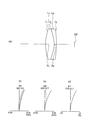
- (A) is a sectional view along the optical axis showing the optical configuration of the loupe optical system according to Example 1, and (b) to (d) are aberration diagrams of the loupe optical system.
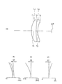
- (A) is a sectional view along the optical axis showing the optical configuration of the loupe optical system according to Example 2, and (b) to (d) are aberration diagrams of the loupe optical system.
- (A) is a sectional view along the optical axis showing the optical configuration of the loupe optical system according to Example 3, and (b) to (d) are aberration diagrams of the loupe optical system.
- (A) is a sectional view along the optical axis showing the optical configuration of the loupe optical system according to Example 4, and (b) to (d) are aberration diagrams of the loupe optical system.
- the microscope system of the present embodiment is a microscope system including a microscope and an observation unit provided separately from the microscope, and the microscope is an image formed through the microscope objective lens and the microscope objective lens.
- An imaging device disposed at a position, and a first control device connected to the imaging device, the observation unit comprising: a second control device; a display device connected to the second control device; and a display device And a magnifying optical system arranged at a predetermined interval, and further comprising communication means for performing communication between the first control device and the second control device, and displaying an image acquired by the image sensor. It is characterized by displaying.
- FIG. 1 is a diagram illustrating a configuration of the microscope system according to the first embodiment
- FIG. 2 is a diagram illustrating a configuration of an observation unit.
- the microscope system 100 includes a microscope 10 and an observation unit 20.
- the microscope 10 includes a light source unit 1, a half mirror 2, a microscope objective lens 3, a revolver 4, a stage 5, an imaging optical system 6, a mirror 7, an afocal optical system 8, and an imaging optical system 9.
- an imaging device 30 includes an imaging element 31 and a control device (first control device) 32.
- the light source unit 1 emits illumination light.
- the illumination light is reflected by the half mirror 2 and then enters the microscope objective lens 3.
- the microscope objective lens 3 is held by the revolver 4 and is positioned below the stage 5.
- a specimen is placed on the stage 5. Therefore, the illumination light emitted from the microscope objective lens 3 is applied to the specimen.
- the light from the specimen passes through the microscope objective lens 3 and the half mirror 2 and enters the imaging optical system 6.
- the light emitted from the imaging optical system 6 is reflected by the mirror 7 and then condensed at a predetermined position. A primary image (optical image) of the specimen is formed at this predetermined position.
- an observation optical path LPa and an imaging optical path LPb are formed.
- An afocal optical system 8 is arranged in the observation optical path LPa, and an imaging optical system 9 is arranged in the imaging optical path LPb.
- An optical element for guiding light to the imaging optical path LPb is disposed between the mirror 7 and the afocal optical system 8.
- the observation unit 20 in this embodiment is detachable from the microscope 10. Therefore, the observation unit 20 is used by being attached to the microscope 10. Further, by detaching the observation unit 20 and attaching a conventional binocular tube to the microscope 10, the observer can observe the sample image (optical image) with the naked eye.
- the imaging device 30 has an imaging element 31.
- the image sensor 31 include a CCD image sensor and a CMOS image sensor.
- the sample image is converted into image data (digital data) by the image sensor 31 and output to the outside.
- the imaging device 30 has a control device 32. Note that the control device 32 may be included in the image sensor 31.
- the observation unit 20 in the present embodiment is separate from the microscope 10 and is detachable from the microscope 10. Therefore, when observing a specimen, the observation unit 20 is attached to the microscope 10. In the observation unit 20, an image of the specimen (digital image) is displayed on the display device, and the observer observes the image. Therefore, in the microscope system of the present embodiment, the microscope 10 necessarily includes the imaging device 30 in order to acquire sample image data.
- the image pickup device 31 may be disposed inside the microscope 10 so that the image pickup apparatus 30 cannot be attached to and detached from the microscope 10. Further, in FIG. 1, an image of the specimen is taken through the imaging optical system 9. However, the image of the sample may be captured by arranging the image sensor 31 at the position of the primary image of the sample without using the imaging optical system 9.
- the structure of the observation unit 20 will be described with reference to FIG.
- the observation unit 20 includes a control device (second control device) 21, a display element 22, and a loupe optical system 23.
- EP represents an eye point.
- the image data of the specimen is acquired by the imaging device 30.
- the acquired specimen image data is input to the display element 22 via the control device 32 and the control device 21.
- the sample image is displayed on the display element 22.
- the observer observes the displayed sample image with the naked eye via the loupe optical system 23.
- the observation unit 20 is different from the conventional binocular tube that observes the optical image of the specimen in that the specimen image, that is, the digital image is observed.
- the only optical component necessary for observing the specimen image is the loupe optical system 23.
- the loupe optical system 23 since fewer optical components are used than in the conventional binocular tube, it is possible to prevent various aberrations, color reproducibility, and image brightness from decreasing. .
- the observer observes the sample image through the observation unit 20.
- the position of the observer's eyes can be kept constant with respect to the observation unit 20 (eye point EP). Therefore, a constant observation magnification can be maintained and an immersive feeling can be obtained, so that concentrated observation can be performed for a long time.
- This basic configuration also includes the microscope system of the following embodiment.
- the display device 22 and the loupe optical system 23 are arranged in the observation unit 20. Therefore, the sample can be observed only by the observation unit 20 only by inputting the image data of the sample to the observation unit 20. This means that the installation position and orientation of the observation unit 20 can be determined regardless of the observation optical path LPa of the microscope 10.
- a mechanical movement mechanism for moving the observation unit 20 in the direction of arrow A is sufficient.
- a mechanical adjustment mechanism for moving in the direction of arrow B is sufficient.
- the microscope system of this embodiment satisfies the following conditional expressions (1A) and (2) after having the above basic configuration.
- ⁇ oc is the magnification of the eyepiece when observing the optical image
- L d is the diagonal length of the display range of the display element
- L i is the diagonal length of the imaging range of the image sensor
- f l is the focal length of the loupe optical system, It is.
- Conditional expressions (1A) and (2) are conditional expressions for obtaining an appropriate observation magnification and viewing angle (2 ⁇ ).
- an image of a specimen is observed using an observation unit.
- the observation magnification and the viewing angle are preferably the same as or substantially the same as the conventional observation magnification and the viewing angle.
- the appropriate observation magnification is preferably within ⁇ 10% of the conventional observation magnification.
- conventional observation magnification here is the magnification of a conventional eyepiece.
- an optical image (primary image) formed through a microscope objective lens is observed using an eyepiece.
- the conventional eyepiece is this eyepiece.
- the “conventional viewing angle” is a viewing angle when observed with a conventional eyepiece.
- the observation magnification when the image of the sample is observed by the observation unit can be the same as or almost equivalent to the conventional observation magnification.
- the viewing angle when the image of the sample is observed with the observation unit can be the same as or substantially equivalent to the conventional viewing angle.
- the viewing angle becomes too small. This is because the number of fields of view is smaller than 18 in terms of the number of fields of view, so the observation range as a microscope becomes too small. If the upper limit of conditional expression (2) is exceeded, the viewing angle becomes too large. This is because the number of fields becomes larger than 35 in terms of the number of fields, so that the flatness of the image (field curvature) cannot be maintained in the microscope objective lens.
- Conditional expression (1A) is used when an image (primary image) formed only by a microscope objective lens is picked up by an image sensor, or an image (primary image) formed only by a microscope objective lens and an imaging lens. ) Is preferably satisfied when imaging is performed with an imaging device.
- the microscope objective lens may be either a finite objective lens or an infinity corrected objective lens.
- the microscope system according to the present embodiment has the above basic configuration, and further includes an intermediate imaging lens between the microscope objective lens and the image sensor, and the following conditional expressions (1B), ( It is preferable to satisfy 2).
- ⁇ oc is the magnification of the eyepiece when observing the optical image
- q is the magnification of the intermediate imaging lens
- L d is the diagonal length of the display range of the display element
- L i is the diagonal length of the imaging range of the image sensor
- f l is the focal length of the loupe optical system, It is.
- conditional expression (1B) is the same as that of conditional expression (1A).
- the technical significance (action and effect) of conditional expression (2) is as described above.
- Conditional expression (1B) indicates that an image (primary image) formed only with a microscope objective lens is imaged with an imaging element via an intermediate imaging lens, or only with a microscope objective lens and an imaging lens. It is preferable to satisfy the case where the formed image is picked up by an image pickup device via an intermediate image forming lens. Further, the microscope objective lens may be either a finite objective lens or an infinity corrected objective lens. When the magnification of the intermediate imaging lens is 1, conditional expression (1B) is the same as conditional expression (1A).
- the microscope system of this embodiment satisfies the following conditional expression (3). 8 ⁇ ⁇ oc ⁇ 30 (3) here, ⁇ oc is the magnification of the eyepiece when observing the optical image, It is.
- conditional expression (3 ′) is preferably satisfied instead of conditional expression (3).
- conditional expression (3 ′′) instead of conditional expression (3).
- ⁇ oc 10 (3 ′′)
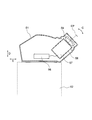
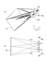
- FIG. 3A and 3B are diagrams showing a loupe optical system, in which FIG. 3A is a perspective view and FIG. 3B is a cross-sectional view along the z-axis direction.
- the observation unit 20 has two display elements and a loupe optical system.
- the loupe optical system shown in FIG. 3 is a loupe optical system of Example 1 described later.
- the observation unit 20 has a display element 22b separately from the display element 22a, and a loupe optical system 23b separately from the loupe optical system 23a.
- the display element 22a and the loupe optical system 23a are disposed on the first optical path LP1. Further, the display element 22b and the loupe optical system 23b are disposed in the second optical path LP2. Thus, the loupe optical system 23a and the loupe optical system 23b are arranged side by side.
- the display element 22a and the display element 22b are also arranged side by side.
- the optical path is defined by a line connecting the center of the eye point EP and the center of the display element 22.
- the optical axis (center axis) of the loupe optical system 23a coincides with the center of the eye point EPa.
- the optical axis (center axis) of the loupe optical system 23b and the center of the eye point EPb also coincide.
- the first optical path LP1 and the second optical path LP2 are parallel. Further, the distance between the first optical path LP1 and the second optical path LP2 is the same as the average eye width of the observer.
- FIG. 4 is a view showing a loupe optical system different from the loupe optical system shown in FIG. 3, and is a cross-sectional view along the z-axis direction.
- the loupe optical system shown in FIG. 4 is a loupe optical system of Example 2 described later.
- the display element 24a and the loupe optical system 25a are disposed in the first optical path LP1.
- the display element 24b and the loupe optical system 25b are disposed in the second optical path LP2.
- the loupe optical system 25a and the loupe optical system 25b are arranged side by side.
- the display element 24a and the display element 24b are also arranged side by side.
- the observation unit in the first embodiment has two display elements and two loupe optical systems, but does not have a reflecting member.
- observation unit 20 may be provided with an adjustment mechanism that changes the interval between the two loupe optical systems.
- the distance between the loupe optical system 23a and the loupe optical system 23b that is, the distance between the eye point EPa and the eye point EPb can be adjusted according to the observer.
- Such an adjustment mechanism may be provided in the microscope systems of the second to fourth embodiments described later.
- a moving mechanism that moves at least one of the two loupe optical systems along the optical axis direction. In this way, the focus can be easily adjusted.
- a moving mechanism may be provided in the microscope systems of the second to fourth embodiments described later.
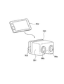
- FIGS. 5A is an overview diagram of the microscope system
- FIG. 5B is an overview diagram of the image processing unit
- FIG. 6 is a diagram illustrating a configuration of the microscope in the microscope system.
- the microscope system 200 includes a microscope 40 and an observation unit 50.
- an image processing system IPS as shown in FIG. 5B may be combined with the microscope system 200 as necessary.
- the image processing unit IPS includes an image processing device IPS1 and a display device IPS2.
- the microscope 40 includes a light source unit 41, a stage 42, a holder 43, a microscope objective lens 44, a revolver 45, an imaging optical system 46, an imaging optical system 47, and an imaging device 60.
- the imaging device 60 includes an imaging element 61 and a control device (first control device) 62. Since the basic configuration of the microscope 40 is the same as that of the microscope 10 in the first embodiment, description of each configuration is omitted.
- the observation unit 50 in the present embodiment is separate from the microscope 40 and cannot be attached to or detached from the microscope 40. Therefore, the observation unit 50 is used separately from the microscope 40. In the observation unit 50, an image of the specimen is displayed on the display device, and the observer observes the image. For this reason, in the microscope system of the present embodiment, the microscope 40 necessarily includes the imaging device 60 in order to acquire sample image data.
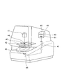
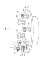
- the observation unit 50 includes an eyepiece 51, a support column 52, a base 53, a first operation unit 54, and a second operation unit 55.
- a support column 52, a first operation unit 54, and a second operation unit 55 are connected to the base 53, and the eyepiece unit 51 is connected to the support column 52.
- the first operation unit 54 and the second operation unit 55 are both rotary knobs. By rotating the knob of the first operation unit 54, the microscope 40 can focus on the specimen. Further, the sample can be moved in the microscope 40 by rotating the knob of the second operation unit 55.
- the second operation unit 55 is provided with two knobs 55a and 55b so that the sample can be moved in two orthogonal directions. The observer can focus the specimen and adjust the observation position by operating the first operation unit 54 and the second operation unit 55 while looking through the eyepiece unit 51.
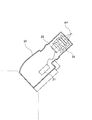
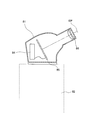
- FIG. 7 is a diagram illustrating the configuration of the eyepiece unit 51.
- the eyepiece 51 includes a control device (second control device) 56, a display element 57, a mirror (reflection member) 58, and a loupe optical system 59.
- the display element 57 is connected to the control device 56.
- the control device 56 communicates with the control device 62 of the imaging device 60. This communication may be wired or wireless.
- the loupe optical system 59 is arranged at a predetermined interval from the display element 57. Further, a mirror 58 is disposed between the display element 57 and the loupe optical system 59. Therefore, the light of the image displayed on the display element 57 is reflected by the mirror 58 and enters the loupe optical system 59.
- the image data of the specimen is acquired by the imaging device 60.
- the acquired sample image data is input to the display element 57 via the control device 62 and the control device 56.
- the sample image is displayed on the display element 57.
- the observer observes the displayed sample image with the naked eye via the mirror 58 and the loupe optical system 59.
- the observation unit 50 is different from the conventional binocular tube that observes the optical image of the specimen in that the specimen image, that is, the digital image is observed.
- the microscope system of the present embodiment only the mirror 58 and the loupe optical system 59 are necessary for observing the specimen image. As described above, in the microscope system of the present embodiment, since fewer optical components are used than in the conventional binocular tube, it is possible to prevent various aberrations, color reproducibility, and image brightness from decreasing. .
- the observer observes the sample image through the observation unit 50.
- the position of the observer's eyes can be kept constant with respect to the observation unit 50 (eye point EP). Therefore, a constant observation magnification can be maintained and an immersive feeling can be obtained, so that concentrated observation can be performed for a long time.
- the microscope system of the present embodiment can also be provided with a mechanism for adjusting the position and elevation angle of the eye point.
- the eyepiece 51 is made of two structures, and the display element 57, the mirror 58, and the loupe optical system 59 are arranged in one structure.
- the elevation angle can be adjusted by rotating one structure with respect to the other structure (arrow C).
- the length of the support column 52 can be changed, the position of the eye point can be moved in the vertical direction (arrow D).
- a slide mechanism is provided at the connecting portion between the eyepiece 51 and the support column 52, the position of the eye point can be moved in the horizontal direction (arrow E).
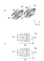
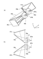
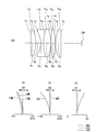
- FIG. 8A and 8B are diagrams showing the loupe optical system, in which FIG. 8A is a perspective view and FIG. 8B is a cross-sectional view along the z-axis direction.
- the eyepiece 51 of the observation unit 50 includes two display elements, mirrors (reflection members), and a loupe optical system.
- the loupe optical system shown in FIG. 8 is a loupe optical system of Example 3 described later.
- the observation unit 50 has a display element 57b separately from the display element 57a, a mirror 58b separate from the mirror 58a, and a loupe optical system 59b separate from the loupe optical system 59a.
- the display element 57a, the mirror 58a, and the loupe optical system 59a are disposed in the first optical path LP1. Further, the display element 57b, the mirror 58b, and the loupe optical system 59b are disposed in the second optical path LP2.
- the loupe optical system 23a and the loupe optical system 23b are arranged side by side.
- the display element 22a and the display element 22b, and the mirror 58a and the mirror 58b are also arranged side by side.
- the optical axis (center axis) of the loupe optical system 59a coincides with the center of the eye point EPa.
- the optical axis (center axis) of the loupe optical system 59b and the center of the eye point EPb also coincide.
- the first optical path LP1 and the second optical path LP2 are parallel. Further, the distance between the first optical path LP1 and the second optical path LP2 is the same as the average eye width of the observer.
- the observation unit in the second embodiment has two display elements, reflecting members, and a loupe optical system.
- f l is the focal length of the loupe optical system, It is.
- the observation unit 50 in this embodiment includes a display element and a loupe optical system, as in the observation unit 20 in the first embodiment, and an observer observes an image displayed on the display element with the loupe optical system. Therefore, also in the microscope system of this embodiment, there exists an effect similar to the microscope system of 1st Embodiment.
- the image processing unit IPS when the image processing unit IPS is combined with the microscope system 200, an image acquired by the imaging device 60 of the microscope 40 can be output to the observation unit 50 via the image processing device IPS1. Therefore, the image processing apparatus IPS1 can perform various image processes on the image data. Further, the image observed by the observation unit 50 can be displayed on the display device IPS2.
- FIG. 9 is a schematic view of the microscope system
- FIG. 10 is a diagram showing the configuration of the observation unit (eyepiece).
- the microscope system 300 includes a microscope 70 and an observation unit 80.
- the microscope 70 includes a light source unit 71, a microscope objective lens 72, a revolver 73, a stage 74, an imaging optical system 75, a binocular tube 76, and an imaging device 90.
- the imaging device 90 is provided with the image pick-up element and the control apparatus (1st control apparatus), it is not illustrated in FIG. Since the basic configuration of the microscope 70 is the same as that of the microscope 10 in the first embodiment, description of each configuration is omitted.
- the observation unit 80 in this embodiment is separate from the microscope 70 and cannot be attached to or detached from the microscope 70. Therefore, the observation unit 80 is used separately from the microscope 70. In the observation unit 80, an image of the specimen is displayed on the display device, and the observer observes the image. For this reason, in the microscope system of the present embodiment, the microscope 70 necessarily includes the imaging device 90 in order to acquire sample image data.
- the observation unit 80 includes an eyepiece 81, a support 82, and a base 83.
- a support 82 is connected to the base 83, and an eyepiece 81 is connected to the support 82.
- the structure of the eyepiece 81 of the observation unit 80 will be described with reference to FIG.
- the eyepiece unit 81 includes a control device (second control device) 84, a display element 85, and a loupe optical system 86.
- the display element 85 is connected to the control device 84.
- the control device 84 communicates with the control device of the imaging device 90. This communication may be wired or wireless.
- the loupe optical system 86 is arranged at a predetermined interval from the display element 85.
- the image data of the specimen is acquired by the imaging device 90.
- the acquired sample image data is input to the display element 85 via the control device and the control device 84.
- the sample image is displayed on the display element 85.
- the observer observes the displayed sample image with the naked eye via the loupe optical system 86.
- the observation unit 80 is different from the conventional binocular tube that observes the optical image of the specimen in that the specimen image, that is, the digital image is observed.
- the only optical component necessary for observing the specimen image is the loupe optical system 86.
- the loupe optical system 86 since fewer optical components are used than in the conventional binocular tube, it is possible to prevent various aberrations, color reproducibility, and image brightness from decreasing. .
- the observer observes the sample image through the observation unit 80.
- the position of the observer's eyes can be kept constant with respect to the observation unit 80 (eye point EP). Therefore, a constant observation magnification can be maintained and an immersive feeling can be obtained, so that concentrated observation can be performed for a long time.
- a mechanism for adjusting the position and elevation angle of the eye point can be provided.
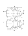
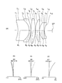
- FIG. 11A and 11B are diagrams illustrating a loupe optical system, in which FIG. 11A is a perspective view and FIG. 11B is a cross-sectional view along the z-axis direction.
- the eyepiece 81 of the observation unit 80 has one display element and two loupe optical systems.
- the loupe optical system shown in FIG. 11 is a loupe optical system of Example 4 described later.
- the eyepiece 81 has a loupe optical system 86b separately from the loupe optical system 86a.
- the loupe optical system 86a is disposed in the first optical path LP1.
- the loupe optical system 86b is disposed in the second optical path LP2.
- the loupe optical system 86a and the loupe optical system 86b are arranged side by side.
- the display element 85 is arranged so as to include the first optical path LP1 and the second optical path LP2.
- the optical axis (center axis) of the loupe optical system 86a does not coincide with the center of the eye point EPa.
- the center of the eye point EPa is located outside the optical axis of the loupe optical system 86a.
- the optical axis (center axis) of the loupe optical system 86b does not coincide with the center of the eye point EPb.
- the center of the eye point EPb is located outside the optical axis of the loupe optical system 86b.
- first optical path LP1 and the second optical path LP2 are not parallel. Further, the distance between the first optical path LP1 and the second optical path LP2 is the same as the average eye width of the observer.
- the observation unit in the third embodiment has one display element and two loupe optical systems, but does not have a reflecting member.
- the observation unit 80 in this embodiment includes a display element and a loupe optical system, as in the observation unit 20 in the first embodiment, and an observer observes an image displayed on the display element with the loupe optical system. Therefore, also in the microscope system of this embodiment, there exists an effect similar to the microscope system of 1st Embodiment.
- the microscope system of the present embodiment has a plurality of observation units 80.
- the microscope system of the present embodiment since fewer optical components are used than in the conventional binocular tube, it is possible to prevent various aberrations, color reproducibility, and image brightness from decreasing. .
- each observation unit 80 an image of the sample acquired by the imaging device 90 is displayed. Therefore, a plurality of observers can observe the same specimen.
- both the microscope 70 and each observation unit 80 can be freely arranged. Therefore, each observer is not forced to have a cramped posture.
- the microscope system according to the fourth embodiment will be described with reference to FIG.
- the microscope of the second embodiment or the microscope of the third embodiment is used as the microscope. Therefore, only the observation unit is shown in FIG. Since the observation unit uses the loupe optical system in the third embodiment, the configuration of the loupe optical system is not shown.
- the observation unit 500 in this embodiment includes a main body 501 and a display element 502.
- the main body 501 is provided with loupe optical systems 86a and 86b.
- the display element 502 is detachable from the main body 501. Therefore, the main body 501 is provided with a mounting portion (groove) 503 for mounting the display element 502.
- a portable information terminal can be used as the display element 502 as the display element 502, a portable information terminal can be used. As a result, the usage of information terminals is expanded.
- the observation unit 500 in this embodiment includes a display element and a loupe optical system, as in the observation unit 20 in the first embodiment, and an observer observes an image displayed on the display element with the loupe optical system. . Therefore, also in the microscope system of this embodiment, there exists an effect similar to the microscope system of 1st Embodiment. Moreover, it is preferable that the observation unit in the fourth embodiment also satisfies the condition (6).
- the observation unit includes a display element that displays an input predetermined image, and a loupe optical system that is disposed at a predetermined interval from the display element.
- ⁇ oc is the magnification of the eyepiece when observing the optical image
- q is the magnification of the intermediate imaging lens
- L d is the diagonal length of the display range of the display element
- L i is the diagonal length of the imaging range of the image sensor
- f l is the focal length of the loupe optical system
- observation unit of the present embodiment it is possible to provide an observation unit that has high optical performance, can keep the observation magnification constant, and can concentrate and observe for a long time.
- an observation unit that can simplify these mechanisms can be provided.
- FIGS. 13 (a) to 16 (a) Cross sections along the optical axis showing the optical configuration of the loupe optical systems according to Examples 1 to 4 are shown in FIGS. 13 (a) to 16 (a), respectively.
- L1 to L6 indicate lenses
- EP indicates an eye point.
- the left side of the paper is the object side and the right side is the image side.
- the loupe optical system of Example 1 includes a planoconvex positive lens L1, a biconcave negative lens L2, a biconvex positive lens L3, a biconvex positive lens L4, and a planoconvex positive lens L5.
- the biconcave negative lens L2 and the biconvex positive lens L3 are cemented.
- the loupe optical system of Example 2 includes a positive meniscus lens L1 having a convex surface facing the image side, a negative meniscus lens L2 having a convex surface facing the image side, a biconvex positive lens L3, and a positive surface having a convex surface facing the object side. It consists of a meniscus lens L4, a plano-convex positive lens L5, and a plano-concave negative lens L6.
- the positive meniscus lens L1 and the negative meniscus lens L2 are cemented.
- the planoconvex positive lens L5 and the planoconcave negative lens L6 are cemented.
- the loupe optical system of Example 3 includes a biconvex positive lens L1 and a negative meniscus lens L2 having a convex surface facing the image side.
- the biconvex positive lens L1 and the negative meniscus lens L2 are cemented.
- the loupe optical system of Example 4 is composed of a positive meniscus lens L1 having a convex surface facing the object side and a negative meniscus lens L2 having a convex surface facing the object side.
- the positive meniscus lens L1 and the negative meniscus lens L2 are cemented.
- the image height is the image height when an image is formed by the loupe optical system and the ideal lens.
- the ideal lens is disposed on the image side (eye point side) of the loupe optical system and has a focal length of 25 mm.
- NA ′ is the numerical aperture on the image side when the ideal lens is disposed.
- FIGS. 13B, 13C, and 13D aberration diagrams of the loupe optical system according to Examples 1 to 4 are shown in FIGS. 13B, 13C, and 13D, respectively, FIGS. 16B, 16C, and 16D.
- “FIY” is the image height.
- (b), (c), and (d) show spherical aberration (SA), astigmatism (AS), and distortion aberration (DT), respectively.
- SA spherical aberration
- AS astigmatism
- DT distortion aberration
- Example 1 Example 2
- Example 3 Example 4 ⁇ oc 10 10 10 10 q 0.5 0.35 0.5 0.5 Ld 22.8 42 115 230 Li 11.4 13 11.4 11.4 fl 25 31.5 120.3 250
- the present invention has a high optical performance, the observation magnification can be kept constant, and a microscope system capable of intensive observation for a long time, a moving mechanism, and an adjustment mechanism are provided. It is suitable for a microscope system that can simplify these mechanisms.
Landscapes
- Physics & Mathematics (AREA)
- General Physics & Mathematics (AREA)
- Optics & Photonics (AREA)
- Chemical & Material Sciences (AREA)
- Analytical Chemistry (AREA)
- Engineering & Computer Science (AREA)
- Multimedia (AREA)
- Computer Vision & Pattern Recognition (AREA)
- Microscoopes, Condenser (AREA)
- Lenses (AREA)
Priority Applications (1)
| Application Number | Priority Date | Filing Date | Title |
|---|---|---|---|
| US14/542,034 US9671604B2 (en) | 2012-05-16 | 2014-11-14 | Observation unit and microscope system equipped with observation unit |
Applications Claiming Priority (2)
| Application Number | Priority Date | Filing Date | Title |
|---|---|---|---|
| JP2012-112810 | 2012-05-16 | ||
| JP2012112810A JP2013238789A (ja) | 2012-05-16 | 2012-05-16 | 観察ユニット、及びこの観察ユニットを備えた顕微鏡システム |
Related Child Applications (1)
| Application Number | Title | Priority Date | Filing Date |
|---|---|---|---|
| US14/542,034 Continuation US9671604B2 (en) | 2012-05-16 | 2014-11-14 | Observation unit and microscope system equipped with observation unit |
Publications (1)
| Publication Number | Publication Date |
|---|---|
| WO2013172194A1 true WO2013172194A1 (ja) | 2013-11-21 |
Family
ID=49583603
Family Applications (1)
| Application Number | Title | Priority Date | Filing Date |
|---|---|---|---|
| PCT/JP2013/062564 Ceased WO2013172194A1 (ja) | 2012-05-16 | 2013-04-30 | 観察ユニット、及びこの観察ユニットを備えた顕微鏡システム |
Country Status (3)
| Country | Link |
|---|---|
| US (1) | US9671604B2 (enExample) |
| JP (1) | JP2013238789A (enExample) |
| WO (1) | WO2013172194A1 (enExample) |
Families Citing this family (5)
| Publication number | Priority date | Publication date | Assignee | Title |
|---|---|---|---|---|
| JPWO2017022670A1 (ja) * | 2015-07-31 | 2018-05-24 | 株式会社nittoh | 接眼光学系および電子ビューファインダー |
| JP6296318B1 (ja) * | 2017-04-28 | 2018-03-20 | アクアシステム株式会社 | 顕微鏡用光学系及びそれを用いた顕微鏡 |
| DE102020101880A1 (de) * | 2020-01-27 | 2021-07-29 | Carl Zeiss Meditec Ag | Mikroskopieverfahren und Mikroskop zur Erzeugung eines Bilds eines Objekts |
| DE202020000635U1 (de) | 2020-02-17 | 2020-06-19 | Carl Zeiss Microscopy Gmbh | Binokularer Digitaltubus für ein Mikroskop |
| PL245406B1 (pl) * | 2021-03-31 | 2024-07-22 | Univ Warszawski | Mikroskop optyczny |
Citations (4)
| Publication number | Priority date | Publication date | Assignee | Title |
|---|---|---|---|---|
| JP2001066513A (ja) * | 1999-08-25 | 2001-03-16 | Olympus Optical Co Ltd | 実体顕微鏡 |
| JP2002196258A (ja) * | 2000-12-27 | 2002-07-12 | Asahi Optical Co Ltd | ビデオ型顕微鏡 |
| JP2008006089A (ja) * | 2006-06-29 | 2008-01-17 | Mitaka Koki Co Ltd | 手術顕微鏡システム |
| JP2009163201A (ja) * | 2007-12-11 | 2009-07-23 | Mitaka Koki Co Ltd | 立体顕微鏡 |
Family Cites Families (19)
| Publication number | Priority date | Publication date | Assignee | Title |
|---|---|---|---|---|
| JPH08278448A (ja) | 1995-04-06 | 1996-10-22 | Nikon Corp | 鏡筒光学系 |
| JPH10213752A (ja) | 1997-01-31 | 1998-08-11 | Nikon Corp | ティーチング中間鏡筒 |
| JPH1172708A (ja) | 1997-08-29 | 1999-03-16 | Nikon Corp | 顕微鏡 |
| JP4245750B2 (ja) * | 1999-10-15 | 2009-04-02 | オリンパス株式会社 | 立体観察装置 |
| JP5000839B2 (ja) * | 2000-09-18 | 2012-08-15 | ヴァンサン・ロウエ | 共焦点用光学走査装置 |
| CN1166972C (zh) * | 2000-09-20 | 2004-09-15 | 奥林巴斯光学工业株式会社 | 倒立型显微镜 |
| US7151246B2 (en) * | 2001-07-06 | 2006-12-19 | Palantyr Research, Llc | Imaging system and methodology |
| US7248716B2 (en) * | 2001-07-06 | 2007-07-24 | Palantyr Research, Llc | Imaging system, methodology, and applications employing reciprocal space optical design |
| DE10203215B4 (de) * | 2002-01-28 | 2004-09-09 | Carl Zeiss Jena Gmbh | Mikroskop, insbesondere Operationsmikroskop |
| US7180660B2 (en) * | 2002-02-04 | 2007-02-20 | Carl-Zeiss-Stiftung Trading As Carl Zeiss | Stereo-examination systems and stereo-image generation apparatus as well as a method for operating the same |
| AU2002311347A1 (en) * | 2002-03-05 | 2003-09-16 | Muradin Abubekirovich Kumakhov | X-ray microscope |
| JP2004298996A (ja) * | 2003-03-31 | 2004-10-28 | Canon Inc | 微小物操作装置 |
| EP1630586B1 (en) * | 2003-06-02 | 2015-01-07 | Nikon Corporation | Microscope device |
| JP2007510963A (ja) * | 2003-11-10 | 2007-04-26 | テクノロジー イノヴェイションズ リミテッド ライアビリティ カンパニー | デジタル画像化組立品、及びその方法 |
| US20060043302A1 (en) * | 2003-11-10 | 2006-03-02 | Prelewitz David F | Digital imaging assembly & methods thereof |
| JP2006162765A (ja) | 2004-12-03 | 2006-06-22 | Keyence Corp | 倒立型蛍光顕微鏡 |
| US7006741B1 (en) * | 2005-03-22 | 2006-02-28 | Bi Yu | Contact-field optical microscope |
| US8477416B2 (en) | 2007-12-11 | 2013-07-02 | Mitaka Kohki Co., Ltd. | Stereomicroscope |
| CN103338690B (zh) * | 2011-05-12 | 2016-04-27 | 奥林巴斯株式会社 | 内窥镜系统 |
-
2012
- 2012-05-16 JP JP2012112810A patent/JP2013238789A/ja active Pending
-
2013
- 2013-04-30 WO PCT/JP2013/062564 patent/WO2013172194A1/ja not_active Ceased
-
2014
- 2014-11-14 US US14/542,034 patent/US9671604B2/en not_active Expired - Fee Related
Patent Citations (4)
| Publication number | Priority date | Publication date | Assignee | Title |
|---|---|---|---|---|
| JP2001066513A (ja) * | 1999-08-25 | 2001-03-16 | Olympus Optical Co Ltd | 実体顕微鏡 |
| JP2002196258A (ja) * | 2000-12-27 | 2002-07-12 | Asahi Optical Co Ltd | ビデオ型顕微鏡 |
| JP2008006089A (ja) * | 2006-06-29 | 2008-01-17 | Mitaka Koki Co Ltd | 手術顕微鏡システム |
| JP2009163201A (ja) * | 2007-12-11 | 2009-07-23 | Mitaka Koki Co Ltd | 立体顕微鏡 |
Also Published As
| Publication number | Publication date |
|---|---|
| US20150070484A1 (en) | 2015-03-12 |
| US9671604B2 (en) | 2017-06-06 |
| JP2013238789A (ja) | 2013-11-28 |
Similar Documents
| Publication | Publication Date | Title |
|---|---|---|
| CN1975504B (zh) | 高功率立体显微镜 | |
| JP5552000B2 (ja) | ファインダー装置および撮像装置 | |
| CN103765292B (zh) | 目镜系统及图像观察装置 | |
| US8081380B2 (en) | Stereoscopic zoom endoscope | |
| JP2016001209A (ja) | 接眼レンズおよび撮像装置 | |
| CN105589192A (zh) | 光学系统、观察光学系统以及光学装置 | |
| WO2013172194A1 (ja) | 観察ユニット、及びこの観察ユニットを備えた顕微鏡システム | |
| JPWO2017022670A1 (ja) | 接眼光学系および電子ビューファインダー | |
| Qin et al. | Multiresolution foveated laparoscope with high resolvability | |
| US10890743B2 (en) | Illumination device and microscope device | |
| JP2018180043A (ja) | 変倍光学系及び撮像装置 | |
| US20160011433A1 (en) | Optical system for imaging an object | |
| JP6406930B2 (ja) | 接眼レンズ及びそれを有する観察装置、撮像装置 | |
| JP2009003105A (ja) | ファインダー光学系及び撮像装置 | |
| JP2012212096A (ja) | 顕微鏡光学系 | |
| JP2008180964A (ja) | 光学系 | |
| JP2019128527A (ja) | 観察装置 | |
| JP6363570B2 (ja) | ファインダーおよび撮像装置 | |
| US9551864B2 (en) | Eyepiece lens and observation apparatus having the same | |
| JP2016095490A (ja) | 光学系、観察光学系および光学装置 | |
| JP2020194127A (ja) | ファインダーおよび撮像装置 | |
| JPWO2019163744A1 (ja) | 内視鏡用変倍光学系及び内視鏡 | |
| US20120281277A1 (en) | Imaging optical system and microscope apparatus | |
| Zimmer | Optical designs for stereomicroscopes | |
| US9417504B2 (en) | Variable magnification finder and imaging apparatus |
Legal Events
| Date | Code | Title | Description |
|---|---|---|---|
| 121 | Ep: the epo has been informed by wipo that ep was designated in this application |
Ref document number: 13790384 Country of ref document: EP Kind code of ref document: A1 |
|
| NENP | Non-entry into the national phase |
Ref country code: DE |
|
| 122 | Ep: pct application non-entry in european phase |
Ref document number: 13790384 Country of ref document: EP Kind code of ref document: A1 |