WO2013168593A1 - 太陽電池モジュールの製造方法 - Google Patents
太陽電池モジュールの製造方法 Download PDFInfo
- Publication number
- WO2013168593A1 WO2013168593A1 PCT/JP2013/062284 JP2013062284W WO2013168593A1 WO 2013168593 A1 WO2013168593 A1 WO 2013168593A1 JP 2013062284 W JP2013062284 W JP 2013062284W WO 2013168593 A1 WO2013168593 A1 WO 2013168593A1
- Authority
- WO
- WIPO (PCT)
- Prior art keywords
- solar cell
- cell module
- main body
- adhesive
- support rail
- Prior art date
- Legal status (The legal status is an assumption and is not a legal conclusion. Google has not performed a legal analysis and makes no representation as to the accuracy of the status listed.)
- Ceased
Links
Images













Classifications
-
- H—ELECTRICITY
- H02—GENERATION; CONVERSION OR DISTRIBUTION OF ELECTRIC POWER
- H02S—GENERATION OF ELECTRIC POWER BY CONVERSION OF INFRARED RADIATION, VISIBLE LIGHT OR ULTRAVIOLET LIGHT, e.g. USING PHOTOVOLTAIC [PV] MODULES
- H02S20/00—Supporting structures for PV modules
-
- F—MECHANICAL ENGINEERING; LIGHTING; HEATING; WEAPONS; BLASTING
- F24—HEATING; RANGES; VENTILATING
- F24S—SOLAR HEAT COLLECTORS; SOLAR HEAT SYSTEMS
- F24S25/00—Arrangement of stationary mountings or supports for solar heat collector modules
- F24S25/10—Arrangement of stationary mountings or supports for solar heat collector modules extending in directions away from a supporting surface
- F24S25/12—Arrangement of stationary mountings or supports for solar heat collector modules extending in directions away from a supporting surface using posts in combination with upper profiles
-
- F—MECHANICAL ENGINEERING; LIGHTING; HEATING; WEAPONS; BLASTING
- F24—HEATING; RANGES; VENTILATING
- F24S—SOLAR HEAT COLLECTORS; SOLAR HEAT SYSTEMS
- F24S25/00—Arrangement of stationary mountings or supports for solar heat collector modules
- F24S25/60—Fixation means, e.g. fasteners, specially adapted for supporting solar heat collector modules
- F24S25/63—Fixation means, e.g. fasteners, specially adapted for supporting solar heat collector modules for fixing modules or their peripheral frames to supporting elements
- F24S25/632—Side connectors; Base connectors
-
- F—MECHANICAL ENGINEERING; LIGHTING; HEATING; WEAPONS; BLASTING
- F24—HEATING; RANGES; VENTILATING
- F24S—SOLAR HEAT COLLECTORS; SOLAR HEAT SYSTEMS
- F24S25/00—Arrangement of stationary mountings or supports for solar heat collector modules
- F24S25/60—Fixation means, e.g. fasteners, specially adapted for supporting solar heat collector modules
- F24S25/65—Fixation means, e.g. fasteners, specially adapted for supporting solar heat collector modules for coupling adjacent supporting elements, e.g. for connecting profiles together
-
- H—ELECTRICITY
- H02—GENERATION; CONVERSION OR DISTRIBUTION OF ELECTRIC POWER
- H02S—GENERATION OF ELECTRIC POWER BY CONVERSION OF INFRARED RADIATION, VISIBLE LIGHT OR ULTRAVIOLET LIGHT, e.g. USING PHOTOVOLTAIC [PV] MODULES
- H02S20/00—Supporting structures for PV modules
- H02S20/10—Supporting structures directly fixed to the ground
-
- H—ELECTRICITY
- H10—SEMICONDUCTOR DEVICES; ELECTRIC SOLID-STATE DEVICES NOT OTHERWISE PROVIDED FOR
- H10F—INORGANIC SEMICONDUCTOR DEVICES SENSITIVE TO INFRARED RADIATION, LIGHT, ELECTROMAGNETIC RADIATION OF SHORTER WAVELENGTH OR CORPUSCULAR RADIATION
- H10F71/00—Manufacture or treatment of devices covered by this subclass
-
- H—ELECTRICITY
- H10—SEMICONDUCTOR DEVICES; ELECTRIC SOLID-STATE DEVICES NOT OTHERWISE PROVIDED FOR
- H10P—GENERIC PROCESSES OR APPARATUS FOR THE MANUFACTURE OR TREATMENT OF DEVICES COVERED BY CLASS H10
- H10P72/00—Handling or holding of wafers, substrates or devices during manufacture or treatment thereof
- H10P72/30—Handling or holding of wafers, substrates or devices during manufacture or treatment thereof for conveying, e.g. between different workstations
- H10P72/32—Handling or holding of wafers, substrates or devices during manufacture or treatment thereof for conveying, e.g. between different workstations between different workstations
- H10P72/3202—Mechanical details, e.g. rollers or belts
-
- H—ELECTRICITY
- H10—SEMICONDUCTOR DEVICES; ELECTRIC SOLID-STATE DEVICES NOT OTHERWISE PROVIDED FOR
- H10P—GENERIC PROCESSES OR APPARATUS FOR THE MANUFACTURE OR TREATMENT OF DEVICES COVERED BY CLASS H10
- H10P72/00—Handling or holding of wafers, substrates or devices during manufacture or treatment thereof
- H10P72/30—Handling or holding of wafers, substrates or devices during manufacture or treatment thereof for conveying, e.g. between different workstations
- H10P72/32—Handling or holding of wafers, substrates or devices during manufacture or treatment thereof for conveying, e.g. between different workstations between different workstations
- H10P72/3211—Changing orientation of the substrate, e.g. from a horizontal position to a vertical position
-
- F—MECHANICAL ENGINEERING; LIGHTING; HEATING; WEAPONS; BLASTING
- F24—HEATING; RANGES; VENTILATING
- F24S—SOLAR HEAT COLLECTORS; SOLAR HEAT SYSTEMS
- F24S25/00—Arrangement of stationary mountings or supports for solar heat collector modules
- F24S25/60—Fixation means, e.g. fasteners, specially adapted for supporting solar heat collector modules
- F24S2025/601—Fixation means, e.g. fasteners, specially adapted for supporting solar heat collector modules by bonding, e.g. by using adhesives
-
- F—MECHANICAL ENGINEERING; LIGHTING; HEATING; WEAPONS; BLASTING
- F24—HEATING; RANGES; VENTILATING
- F24S—SOLAR HEAT COLLECTORS; SOLAR HEAT SYSTEMS
- F24S25/00—Arrangement of stationary mountings or supports for solar heat collector modules
- F24S2025/80—Special profiles
- F24S2025/804—U-, C- or O-shaped; Hat profiles
-
- Y—GENERAL TAGGING OF NEW TECHNOLOGICAL DEVELOPMENTS; GENERAL TAGGING OF CROSS-SECTIONAL TECHNOLOGIES SPANNING OVER SEVERAL SECTIONS OF THE IPC; TECHNICAL SUBJECTS COVERED BY FORMER USPC CROSS-REFERENCE ART COLLECTIONS [XRACs] AND DIGESTS
- Y02—TECHNOLOGIES OR APPLICATIONS FOR MITIGATION OR ADAPTATION AGAINST CLIMATE CHANGE
- Y02E—REDUCTION OF GREENHOUSE GAS [GHG] EMISSIONS, RELATED TO ENERGY GENERATION, TRANSMISSION OR DISTRIBUTION
- Y02E10/00—Energy generation through renewable energy sources
- Y02E10/40—Solar thermal energy, e.g. solar towers
- Y02E10/47—Mountings or tracking
-
- Y—GENERAL TAGGING OF NEW TECHNOLOGICAL DEVELOPMENTS; GENERAL TAGGING OF CROSS-SECTIONAL TECHNOLOGIES SPANNING OVER SEVERAL SECTIONS OF THE IPC; TECHNICAL SUBJECTS COVERED BY FORMER USPC CROSS-REFERENCE ART COLLECTIONS [XRACs] AND DIGESTS
- Y02—TECHNOLOGIES OR APPLICATIONS FOR MITIGATION OR ADAPTATION AGAINST CLIMATE CHANGE
- Y02E—REDUCTION OF GREENHOUSE GAS [GHG] EMISSIONS, RELATED TO ENERGY GENERATION, TRANSMISSION OR DISTRIBUTION
- Y02E10/00—Energy generation through renewable energy sources
- Y02E10/50—Photovoltaic [PV] energy
Definitions
- This invention relates to the manufacturing method of the solar cell module which adhere
- the back surface of the solar cell module main body and a bonding surface of the support member (for example, a long support member) to the solar cell module main body are bonded via an adhesive member (see, for example, Patent Document 1).
- a front surface electrode, a semiconductor layer, and a back surface electrode are laminated in this order on a light receiving side member (for example, a light receiving surface glass) constituting a light receiving surface to form a solar cell string.
- a back side member for example, a back glass or a back back sheet constituting the back surface is bonded together, and the space between the light receiving side member and the back side member is sealed. Moreover, it may stick together, heating a solar cell module main body.
- the physical properties such as the thickness and material of the light receiving side member (for example, the light receiving surface glass), the physical properties such as the thickness and material of the back side member (for example, the back glass and the back back sheet) constituting the back surface of the semiconductor layer.
- the physical properties such as the thickness and material of the light receiving side member (for example, the light receiving surface glass), the physical properties such as the thickness and material of the back side member (for example, the back glass and the back back sheet) constituting the back surface of the semiconductor layer.
- warping may occur because the thickness and physical properties of the front electrode, the semiconductor layer, and the back electrode are different. This is particularly noticeable when the solar cell module bodies are bonded together while heating.
- the solar cell module main body when the solar cell module main body is warped, when the back surface of the solar cell module main body and the adhesion surface of the support member to the solar cell module main body are bonded via the adhesive member, the warpage of the solar cell module main body is caused.
- the solar cell module main body and the support member may not be securely bonded.
- the present invention provides a solar cell module main body even when the solar cell module main body is warped when the back surface of the solar cell module main body and the adhesion surface of the support member to the solar cell module main body are bonded via the adhesive member. It aims at providing the manufacturing method of the solar cell module which can adhere
- the present inventor has found the following as a result of repeated trial and error in order to solve the above problems.
- the solar cell module main body when the back surface of the solar cell module main body and the adhesion surface of the support member to the solar cell module main body are bonded via the adhesive member, for example, the solar cell module main body is placed on the mounting table with the back surface of the solar cell module main body facing up.
- the support member becomes a solar cell if the solar cell module main body is warped. Since the inclination tends to be inclined in the direction of warping of the module body, even if the support member and a part of the solar cell module main body are bonded via the adhesive member, the support member and the solar cell module main body are not bonded in the other portions.
- the support member is a long member, and when the solar cell module main body warped in the longitudinal direction of the long support member is bonded, further speaking, the solar cell module main body is long. This is particularly noticeable when the support members are laminated in a plurality in the longitudinal direction.
- the support member is mounted on the mounting table with the bonding surface of the support member facing up, and the bonding surface of the support member mounted on the mounting table and the back surface of the solar cell module body are interposed via the bonding member.
- the present invention is based on such knowledge, and is a method for manufacturing a solar cell module in which a back surface of a solar cell module body and a bonding surface of a support member to the solar cell module body are bonded via an adhesive member, The step of mounting the support member on a mounting table with the bonding surface of the support member facing up, and bonding the bonding surface of the support member mounted on the mounting table and the back surface of the solar cell module body.
- the manufacturing method of the solar cell module characterized by including the process of bonding together through a member is provided.
- the support member is mounted on a mounting table with the bonding surface of the support member facing up, and the bonding surface of the support member mounted on the mounting table and the solar cell module main body A portion where the solar cell module main body is most separated between the solar cell module main body and the support member even if the solar cell module main body is warped by bonding the back surface via the adhesive member. Therefore, the solar cell module body and the support member can be reliably bonded to each other.
- the solar cell module body can be bonded in a state close to the environment where the solar cell module is actually installed in order to bond the solar cell module body with the light receiving surface facing upward, and the solar cell
- the stress applied to the adhesive member can be reduced by changing the attitude of the solar cell module between when the adhesive member is cured in the module and when the solar cell module with the adhesive member cured is installed.
- a mode in which the back surface of the solar cell module main body is bonded to the bonding surface of the support member by the weight of the solar cell module main body It can be illustrated.
- the back surface of the solar cell module main body is bonded to the bonding surface of the support member by the own weight of the solar cell module main body, so that the solar cell module main body is caused by the own weight of the solar cell module main body. It is possible to easily and easily fit in the stable posture.
- a mode in which the adhesive surface of the support member is placed horizontally or substantially horizontally on the mounting table can be exemplified.
- the solar cell is maintained in a state where the horizontal or substantially horizontal orientation of the solar cell module body is maintained by placing the adhesive surface of the support member horizontally or substantially horizontally on the mounting table. It becomes possible to adhere the module body stably.
- the support member can be exemplified as an elongated member.
- a mode in which the solar cell module main body warped in the longitudinal direction of the long support member is bonded can be exemplified.
- an adhesion failure that is likely to occur when the solar cell module main body warped in the longitudinal direction of the long support member is bonded (that is, the support member is lifted from the solar cell module main body). (Adhesion failure) can be reliably suppressed.
- a mode in which the solar cell module main body is bonded in a plurality in the longitudinal direction of the support member can be exemplified.
- an adhesion failure that is likely to occur when the solar cell module main body is laminated in a plurality in the longitudinal direction of the support member that is, an adhesive that causes the support member to float from the solar cell module main body. (Defective) can be reliably suppressed. Thereby, the dispersion
- the support member placed on the mounting table is positioned by the support member positioning portion, and the adhesive surface of the support member The aspect which bonds the back surface of the said solar cell module main body through the said adhesive member can be illustrated.
- the solar cell module is bonded by bonding the adhesive surface of the support member and the back surface of the solar cell module body with the support member positioned by the support member positioning portion.
- the battery module main body and the support member can be bonded in a state of being accurately aligned.
- the adhesive surface of the support member placed on the mounting table and the back surface of the solar cell module main body are interposed via the adhesive member. Then, the solar cell module main body positioning portion can be exemplified by the solar cell module main body positioning portion for bonding.
- the solar cell module main body is positioned by the solar cell module main body positioning portion between the adhesive surface of the support member placed on the mounting table and the back surface of the solar cell module main body via the adhesive member. By adhering while positioning, the solar cell module main body and the support member can be bonded in a state of being accurately aligned.
- any member can be used as long as it can maintain an appropriate adhesive strength when the back surface of the solar cell module body and the adhesive surface of the support member are bonded together. It is good and can illustrate adhesive members, such as an adhesive and a double-sided pressure sensitive adhesive sheet.
- the adhesive for example, a two-component silicone adhesive can be used.
- the solar cell module main body when the back surface of the solar cell module main body and the adhesive surface of the support member are bonded via the adhesive member, the solar cell module main body is warped. Also, the solar cell module main body and the support member can be securely bonded.
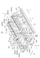
- FIG. 1 is a schematic perspective view showing an overall configuration of a photovoltaic power generation system in a state in which subunits integrally assembled with a solar cell module body according to an embodiment of the present invention are arranged on a gantry.
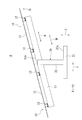
- FIG. 2 is a schematic left side view of the photovoltaic power generation system shown in FIG.
- FIG. 3 is a schematic exploded perspective view showing a state before the subunit is installed on the gantry.
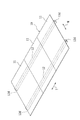
- FIG. 4 is a diagram illustrating a schematic configuration of the subunit according to the present embodiment, and is a schematic perspective view of the subunit as viewed from the light receiving surface side.
- FIG. 1 is a schematic perspective view showing an overall configuration of a photovoltaic power generation system in a state in which subunits integrally assembled with a solar cell module body according to an embodiment of the present invention are arranged on a gantry.
- FIG. 2 is a schematic left side view of the photovoltaic power generation system shown in FIG.
- FIG. 3 is
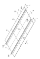
- FIG. 5 is a diagram showing a schematic configuration of the subunit according to the present embodiment, and is a schematic perspective view of the subunit as viewed from the back surface side opposite to the light receiving surface.
- FIG. 6 is a diagram showing a schematic configuration of a subunit according to the present embodiment, and is a schematic perspective view showing one solar cell module body in an exploded state when the subunit is viewed from the back side.
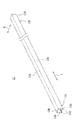
- FIG. 7 is a schematic perspective view showing the support rail shown in FIGS. 1 to 6.
- FIG. 8 is a schematic cross-sectional view showing the support rail shown in FIGS. 1 to 6.
- FIG. 9 is a schematic side view of the support rail provided with each solar cell module main body as viewed from the vertical direction.
- FIG. 10 is a schematic perspective view of a state in which the receiving portion is attached and fixed to the vertical rail as viewed obliquely from above.
- FIG. 11 is a schematic perspective view of a state in which the receiving portion is attached and fixed to the vertical rail as viewed obliquely from below.
- 12 is a schematic cross-sectional view taken along the line D1-D1 in FIGS. 10 and 11, showing a state in which the receiving portion is attached and fixed to the vertical beam.
- FIG. 13 is a schematic exploded perspective view of a state in which the installation end portions of the support rails adjacent to each other in the left-right direction are abutted with respect to the receiving portion fixed to the vertical rail and are fixed by the fixing tool from obliquely above. .
- FIG. 13 is a schematic exploded perspective view of a state in which the installation end portions of the support rails adjacent to each other in the left-right direction are abutted with respect to the receiving portion fixed to the vertical rail and are fixed by the fixing tool
- FIG. 14 shows the state where the installation ends of the support rails adjacent to each other in the left-right direction are abutted against the receiving part fixed to the vertical rail, and are fixed by a fixing tool along the line D2-D2 in FIGS. It is a schematic sectional drawing in alignment with.
- FIG. 15 is an explanatory diagram for explaining the inconvenience in the case where the back surface of the solar cell module body placed on the mounting table with the back surface facing up is bonded to the adhesive surface of the support rail via an adhesive, It is the schematic diagram which looked at the state by which a support rail and a single solar cell module main body are bonded together from the direction (vertical direction) orthogonal to a curvature direction.
- FIG. 16 is an explanatory diagram for explaining inconveniences in the case where the back surface of the solar cell module body mounted on the mounting table and the adhesive surface of the support rail are bonded together with an adhesive, with the back surface facing up, It is the schematic diagram which looked at the state where a support rail and a plurality of solar cell module main bodies are pasted together from the direction (longitudinal direction) orthogonal to the direction of curvature.
- FIG. 17 is a schematic perspective view showing an example of a bonding apparatus used in a bonding process for bonding the solar cell module main body and the support rail.
- 18 is a schematic side view showing the bonding apparatus shown in FIG. FIG.
- FIG. 19 is a schematic side view showing a bonding process between the solar cell module main body and the support rail using the bonding apparatus shown in FIGS. 17 and 18, and (a) shows an adhesive on the back surface of the solar cell module main body.
- FIG. 6B is a diagram illustrating a coating process for coating the solar cell module main body and the support rail in a bonding process in which the back surface of the solar cell module main body and the support rail are bonded via an adhesive.
- (C) is a figure which shows the state after bonding a solar cell module main body and a support rail in the bonding process shown to (b).
- FIG. 20 shows a plurality (in a warped state of the support rail when the adhesive surface of the support rail mounted on the mounting table and the back surface of the solar cell module body are bonded together with an adhesive. It is the schematic diagram seen from the direction (longitudinal direction) orthogonal to the direction of warpage of an example of the state where three solar cell module main bodies are pasted together here.
- FIG. 21 is a schematic perspective view showing an example of the mounting table.
- FIG. 22 is a schematic side view of the mounting table shown in FIG.
- FIG. 23 is a schematic cross-sectional view along the line GG of the mounting table shown in FIG.
- FIG. 24 is a schematic perspective view illustrating a switching device that switches between a protruding position and a retracted position of the second support rail positioning portion.
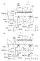
- FIG. 25 is an enlarged schematic cross-sectional view showing an end portion on the downstream side in the transport direction of the mounting table, and (a) shows a state in which the second support rail positioning portion is located at the protruding position.
- (B) is a figure which shows the state in which the positioning part for 2nd support rails is located in a retracted position.
- FIG. 26 is a schematic perspective view of the downstream end in the transport direction of the mounting table as viewed obliquely from the center to the outside in the width direction.
- FIG. 27 is a schematic perspective view illustrating another example of the bonding apparatus illustrated in FIGS. 17 to 19, in which an adhesive is applied to the bonding surface of the support rail.
- FIG. 28 is a schematic perspective view showing a state of a subunit obtained by bonding the solar cell module main body on the support rail by the bonding apparatus shown in FIGS. 17 to 19 and 27.
- FIG. 1 is a schematic perspective view showing an overall configuration of a photovoltaic power generation system A in a state in which a subunit 10 in which a solar cell module body 11 according to an embodiment of the present invention is integrally assembled is disposed on a gantry 20.
- FIG. 2 is a schematic left side view of the photovoltaic power generation system A shown in FIG.
- FIG. 3 is a schematic exploded perspective view showing a state before the subunit 10 is installed on the gantry 20.
- the direction in which the foundations 21 are arranged toward the front is the left-right direction X
- the direction orthogonal to both the left-right direction X and the vertical direction (up-down direction) Z is The front-rear direction Y is assumed
- the inclination direction of the vertical beam 23 is the upper-lower diagonal direction W.
- the longitudinal direction of the solar cell module main body 11 is defined as a vertical direction N
- the short direction of the solar cell module main body 11 is defined as a horizontal direction T.
- 1 is configured so that it can be used as a solar power plant, for example.
- the solar power generation system A includes a subunit 10 that functions as a solar cell module including a solar cell module body 11 and a support rail 12 (an example of a support member), and a gantry 20 that supports the subunit 10.
- the gantry 20 is provided in a plurality (in this case, n + 1) in the horizontal direction X.
- n + 1 in the horizontal direction X.
- Each of the mounts 20 to 20 constitutes a support structure for the subunit 10, and includes a foundation 21, an arm member 22, and a vertical beam 23 made of concrete or the like.
- Each of the arm member 22 and the vertical rail 23 is formed of a steel material such as a steel plate.
- n + 1 a plurality (here, n + 1) of foundations 21 to 21 are laid on the ground at equal intervals in the left-right direction X, and the arm member 22 is fixed to each foundation 21.
- each base 21 is erected in the vertical direction Z by burying the lower end portion of the arm member 22 in the center of the upper surface 21a.
- the arm member 22 supports the vertical beam 23 by connecting the central part in the vertical direction N of the vertical beam 23 at the upper end portion with a connection member R (see FIGS. 1 and 3) such as a bolt and a nut.
- the vertical rail 23 is provided on the arm member 22 in a state where it is inclined at a predetermined angle so that the rear side is high and the front side is low in the front-rear direction Y.
- the support rail 12 in the sub unit 10 is bridged along the left-right direction X between the vertical rails 23, 23 provided on the arm members 22, 22 in the bases 21, 21 adjacent to each other in the left-right direction X. It is installed on the crosspieces 23 and 23.
- the installation end portions 12d and 12d on both sides of the support rails 12 and 12 are fitted into receiving portions 25 to 25 attached to a plurality of front sides (two in this case) of the mounting inclined surfaces 23a and 23a of the vertical rails 23 and 23, respectively. It has a structure that can be inserted.
- a plurality of (two in this case) supports that are bonded and fixed to the back surfaces of the solar cell module bodies 11 to 11 via an adhesive B (see FIG. 6 described later).
- the installation end portions 12d and 12d on both sides of the rails 12 and 12 are fitted into receiving portions 25 to 25 attached to a plurality of places (two places here) on the rear side of the mounting inclined surfaces 23a and 23a of the vertical bars 23 and 23. It has a structure.
- FIG. 4 to 6 show a schematic configuration of the subunit 10 according to the present embodiment.
- FIG. 4 is a schematic perspective view of the subunit 10 as viewed from the light receiving surface side
- FIG. 5 is a schematic perspective view of the subunit 10 as viewed from the back side opposite to the light receiving surface.
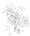
- FIG. 6 is a schematic perspective view showing one solar cell module body 11 in an exploded state when the subunit 10 is viewed from the back side.
- the sub unit 10 includes one or more (here, three connected in the left-right direction X) solar cell module bodies 11 to 11 and one or more (here in the lateral direction T) that also serve as attachments to the gantry 20. 2) supporting rails 12 and 12 arranged in the longitudinal direction N so as to be parallel to each other.
- the solar cell module body 11 has a rectangular flat plate shape.
- the solar cell group 11a is sandwiched between the light receiving surface glass 11b and the back surface glass 11c, It has a structure in which the ends of both glasses 11b and 11c are sealed. That is, in this embodiment, the solar cell module body 11 is a thin film solar cell module having a laminated glass structure, and has a frameless structure.
- the solar cell module main body 11 is not limited to the laminated glass structure, and may be of a back-side back sheet type using a film-like back sheet instead of the back glass 11c.
- the solar cell module body 11 includes a solar cell group 11a including a plurality of solar cells in which a surface electrode (transparent electrode film), a semiconductor layer (photoelectric conversion layer), and a back electrode (back electrode film) (not shown) are sequentially stacked. Is formed. Specifically, a solar cell string is formed by laminating a surface electrode (not shown), a semiconductor layer, and a back electrode in this order on a substrate of a light-receiving surface glass 11b that is a translucent substrate, and a protective plate on the back electrode side. The solar cell module main body 11 is formed by pasting the translucent back glass 11c and sealing between the two glasses 11b and 11c.
- the elongate support rail 12 formed in the shape which can attach the solar cell module main body 11 to the mount frame 20 is the back surface of the solar cell module main body 11 (here outer surface of the back surface glass 11c).
- the solar cell module body 11 is arranged and fixed along the transverse direction T which is the width direction of the solar cell module body 11.
- the subunit 10 includes a plurality of (here, three) solar cell module bodies 11 to 11 arranged in the lateral direction T, and a plurality of (here, two) support rails 12, 12 are arranged in parallel to each other at a certain interval in the vertical direction N perpendicular to the direction of the boundary between the solar cell module bodies 11, 11 adjacent in the horizontal direction T.
- the subunit 10 is connected to the back surface of each of the solar cell module bodies 11 to 11 (here, the outer surface of the back glass 11c) and the solar cell module body 11 of the support rails 12 and 12 via the adhesive B (see FIG. 6).
- the solar cell module main bodies 11 to 11 are connected and supported by the support rails 12 and 12 by being overlapped and bonded to the side surface.
- a slight gap (for example, about 1 cm) may be provided between the solar cell module bodies 11 and 11 adjacent to each other in the horizontal direction T from the viewpoint of avoiding damage due to mutual contact, and adjacent to the left and right direction X.
- the matching solar cell module bodies 11 to 11 may be brought into contact with each other.
- the subunit 10 can be mounted and fixed on the gantry 20 stably without rattling.
- the support rails 12 are arranged in parallel along the horizontal direction T with a certain interval in the vertical direction N of the solar cell module main body 11, but in this embodiment, the back surface of the solar cell module main body 11 is arranged.
- the center line ⁇ parallel to the horizontal direction T passing through the center position in the vertical direction N is provided at a position that is symmetric or substantially symmetric.
- the arrangement position of the support rail 12 is a position that is brought inward in the vertical direction N by a predetermined distance t (see FIG. 5) from both end edges in the vertical direction N of the solar cell module body 11. Yes.
- the support rails 12 to 12 are disposed at positions that are located inward in the vertical direction N by a distance t from both ends in the vertical direction N of the solar cell module body 11, so that the sun applied to the support rails 12 to 12.
- the weight of the battery module body 11 can be distributed in a well-balanced manner, whereby the weight distribution to the support rails 12 to 12 can be made uniform.
- the solar cell module body 11 has a rectangular shape in plan view with a length in the vertical direction N of about 1400 mm and a length in the horizontal direction T of about 1000 mm.
- Each of the support rails 12 to 12 is arranged at a position close to each other by a distance t of about 300 mm from both end edges in the vertical direction N of the solar cell module body 11 to the inner side in the vertical direction N.
- it is not limited to these numerical values.
- positioning position of the support rail 12 is made into the center position of the both-ends edge and the centerline (alpha) in the vertical direction N of the solar cell module main body 11.
- FIGS. 7 and 8 are a schematic perspective view and a schematic cross-sectional view showing the support rail 12 shown in FIGS. 1 to 6, respectively.
- FIG. 9 is a schematic side view of the support rail 12 provided with each solar cell module body 11 as viewed from the vertical direction N.
- the support rail 12 is a long main plate 12a, side plates 12b and 12b that are bent on both long sides in the lateral direction T of the main plate 12a, and inner sides of the side plates 12b and 12b that are bent inward.
- the folded reinforcing portions 12c and 12c are bent upward.
- the support rail 12 has a substantially lip groove steel shape (U-shaped cross-sectional shape) in cross-sectional shape. Further, the support rail 12 has installation end portions 12d at the lower side of both end portions of the side plates 12b and both end portions of the folded back reinforcing portions 12c.
- the support rail 12 having such a configuration can be formed by punching and bending a steel plate and plating the surface.
- the support rail 12 can realize an improvement in bending strength due to the shape of a substantially lip groove steel (U-shaped cross-sectional shape). For this reason, the solar cell module main body 11 can be firmly supported by the support rail 12.
- each of the support rails 12 and 12 has a length d1 in the lateral direction T (see FIG. 9), and a length d2 in the lateral direction T of each of the solar cell module bodies 11 to 11 in the subunit 10 (see FIG. 9). Is slightly larger than. Then, the protruding amount d3 (see FIG. 9) at both ends in the left-right direction X of each support rail 12, 12 protruding from both end positions in the left-right direction X of the entire solar cell module bodies 11 to 11 in the subunit 10. Match each other.
- Each of the support rails 12 and 12 has a length d1 in the horizontal direction T that is the same as or substantially the same as a length d2 in the horizontal direction T of each of the solar cell module main bodies 11 to 11 in the subunit 10. Also good.
- both end positions in each of the support rails 12 and 12 and each end position in the left-right direction X of each of the solar cell module main bodies 11 to 11 in the subunit 10 can be made to coincide with each other.
- a slight gap (for example, 1 cm) between the subunits 10 and 10 adjacent to each other in the horizontal direction T (the solar cell module body 11 at the left end or the right end in the horizontal direction T) from the viewpoint of avoiding damage due to mutual contact.
- the subunits 10 and 10 (the solar cell module main body 11 at the left end or the right end in the horizontal direction T) adjacent to each other in the horizontal direction T may be brought into contact with each other. Further, similarly to the case of the horizontal direction T, damage due to mutual contact is avoided between the subunits 10 and 10 adjacent to each other in the vertical direction N (the solar cell module body 11 at the upper end or the lower end of the vertical direction N). A slight gap (for example, about 1 cm) may be provided from the viewpoint, and the subunits 10 and 10 adjacent to each other in the vertical direction N (the solar cell module body 11 at the upper end or the lower end in the vertical direction N) are brought into contact with each other. Also good.
- FIG. 10 is a schematic perspective view of the state in which the receiving portion 25 is attached and fixed to the vertical beam 23 as viewed obliquely from above. Note that a plurality of (four in this case) receiving portions 25 are provided in one vertical cross 23, and the mounting configuration of the vertical cross 23 and the receiving portion 25 is substantially the same. Therefore, in FIG. 10 and FIGS. 11 to 14 to be described later, a single vertical rail 23 and a receiving portion 25 are shown as a representative configuration.
- FIG. 11 is a schematic perspective view of the state in which the receiving portion 25 is attached and fixed to the vertical beam 23 as viewed obliquely from below.
- 12 is a schematic cross-sectional view taken along the line D1-D1 of FIGS. 10 and 11 showing a state in which the receiving portion 25 is attached and fixed to the vertical rail 23.
- FIG. 13 shows a state in which the installation end portions 12d and 12d of the support rails 12 and 12 adjacent to each other in the left and right direction X face each other with respect to the receiving portion 25 fixed to the vertical beam 23 and are fixed by the fixture 24. It is the general
- FIG. 12 is a schematic cross-sectional view taken along line D2-D2 of FIGS. 10 and 11.
- a through hole 23c through which the male screw S1 passes is provided at a position where the receiving portion 25 of the upper side plate 23b constituting the mounting inclined surface 23a of the vertical rail 23 is provided.
- the receiving portion 25 includes an installation plate 25a provided on the mounting inclined surface 23a of the vertical rail 23, and side plates 25b and 25b bent upward at both ends of the installation plate 25a in the vertical inclination direction W. Yes.
- the installation plate 25a is provided with a female screw hole 25e for screwing the screw portion S1a of the male screw S1.
- the through hole 23c of the vertical beam 23 is larger than the size of the female screw hole 25e of the receiving portion 25 screwed with the male screw S1, and smaller than the size of the head S1b of the male screw S1.
- the receiving portion 25 is arranged on the upper side plate 23b of the vertical rail 23, and the male screw S1 passes through the through hole 23c from the lower side of the side plate 23b to receive the female screw hole 25e of the receiving portion 25.
- the receiving portion 25 can be securely fixed to the upper side plate 23b of the vertical rail 23 by screwing together.
- the bottom surface 25c of the installation plate 25a allows the movement of the receiving portion 25 in the up-and-down inclination direction W and restricts the movement of the receiving portion 25 in the left-right direction X.
- a restricting rib 25d (see FIGS. 11, 12, and 14) is provided.
- the restricting ribs 25d are provided in the left-right direction X at an interval approximately equal to the width in the left-right direction X of the upper side plate 23b of the vertical rail 23.
- the female screw hole 25e is located between the regulating ribs 25d to 25d provided at intervals in the left-right direction X.
- the receiving portion 25 is disposed on the upper side plate 23b of the vertical rail 23, and the male screw S1 is located below the side plate 23b in a state where movement in the left-right direction X is restricted by the restriction ribs 25d to 25d.
- the receiving portion 25 can be reliably fixed to the upper side plate 23 b in the vertical beam 23.
- the regulation ribs 25d to 25d are also provided at intervals in the up and down inclination direction W.
- the restriction ribs 25d to 25d are provided in a total of four places, two places in the left-right direction X and two places in the up-down inclination direction W.
- the female screw hole 25e is located at the center of the intersection of diagonal lines passing through the four regulating ribs 25d to 25d.
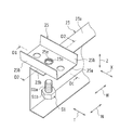
- the fixture 24 includes a bottom plate 24a, inclined plates 24b and 24b that are bent obliquely upward and outward at two opposite sides of the bottom plate 24a in the vertical inclination direction W, and inclined plates 24b. , 24b and side plates 24d, 24d bent downward at upper sides 24c, 24c.
- the fixture 24 having such a configuration can be formed by punching and bending a steel plate and plating the surface.
- the lower ends 24e of the side plates 24d, 24d are formed in a number of triangular mountain shapes (triangular teeth) along the left-right direction X. By doing so, the installation end portions 12d and 12d of the support rails 12 and 12 can be securely held and fixed to the receiving portion 25.
- the bottom plate 24a of the fixture 24 is provided with a through hole 24f through which the threaded portion S1a of the male screw S1 passes.
- two female screw holes 24g and 24g respectively screwed into the two male screws S2 and S2 at the symmetrical positions on both sides in the left-right direction X through the through holes 24f in the bottom plate 24a of the fixture 24 (see FIG. 13).
- the receiving portion 25 has two through holes 25h and 25h through which the screw portions S2a and S2a of the two male screws S2 and S2 screwed into the two female screw holes 24g and 24g provided in the fixture 24, respectively. (See FIG.
- the fixture 24 is placed on the installation end portions 12d and 12d of the support rails 12 and 12 adjacent to each other in the left-right direction X, which is placed and abutted on the installation plate 25a of the receiving portion 25.
- the two male screws S2 and S2 pass through the two through holes 25h and 25h of the receiving part 25 and are screwed into the two female screw holes 24g and 24g of the fixture 24, respectively.
- the fixed ends 24d and 12d of the support rails 12 and 12 adjacent in the left and right direction X can be reliably fixed to the receiving portion 25 by the fixed fixture 24.
- the two female screw holes 24g, 24g have virtual centers ⁇ passing through the center ⁇ parallel to the left-right direction X on both sides of the left-right direction X with the center between the centers ⁇ (see FIG. 13) of the through-hole 24f. (See FIG. 13).
- the distance between one female screw hole 24g and the center ⁇ of the through hole 24f and the distance between the other female screw hole 24g and the center ⁇ of the through hole 24f are the same distance.
- a plurality of solar cell module bodies 11 are connected in parallel, and the support rails 12 and 12 are bonded to the back surfaces of the plurality of solar cell module bodies 11 to 11 via an adhesive B. Yes. This makes it possible to increase the size of the subunit 10 with a simple configuration.
- the adjacent subunits 10 and 10 are arranged so as to be adjacent to each other with almost no gap, and the installation plate 25a of the receiving portion 25 and the solar cell module main bodies 11 to 11 are arranged.
- An operation for fixing the installation end portions 12d and 12d of each of the support rails 12 to 12 to the gantry 20 with the fixture 24 can be performed through the opening provided between the back surface and the back surface.
- the subunits 10 and 10 can be reliably fixed in a state where the adjacent subunits 10 and 10 are arranged so as to be adjacent to each other with almost no gap. Therefore, it is possible to increase the power generation efficiency while reducing the space between the adjacent subunits 10 and 10.
- the strength of the fixture 24 and the gantry 20 can be maintained without particularly restricting the size of the fixture 24 and the gantry 20, and thereby The support strength of the stable support structure of the units 10 to 10 can be ensured.
- work which mounts the fixing tool 24 from the back side on the installation edge part 12d of each support rail 12 and 12d adjacent to the left-right direction X mounted on the installation board 25a of the receiving part 25 and faced
- the fixture 24 is inserted into the opening 12e by being inclined or rotated 90 ° obliquely in a state along the longitudinal direction (left-right direction X) of the one support rail 12.
- the male screw which returns to the original posture in the support rail 12 and then moves in the left-right direction X to be positioned on the receiving portion 25 and is screwed into the female screw hole 25e of the receiving portion 25 to protrude upward.
- the fixture 24 is placed on the receiving portion 25 (more precisely, each side plate 24d, 24d of the fixture 24 is supported by the support rail 12).
- 12 can be placed on the inner surfaces of the folded reinforcing portions 12c, 12c of the installation end portions 12d, 12d.
- the positions of the two female screw holes 24g, 24g of the fixture 24 and the two through holes 25h, 25h of the receiving portion 25 substantially coincide with each other.
- the installation ends of the support rails 12, 12 are passed through the two through holes 25 h, 25 h of the receiving portion 25 and screwed into the two female screw holes 24 g, 24 g of the fixture 24, respectively.
- the portions 12d and 12d can be fixed to the receiving portion 25, that is, the vertical beam 23.
- the fixing of the installation end 12d on the side where the subunit 10 does not exist (terminal position) next to the support rail 12 in the left-right direction X is fixed to the receiving portion 25 here. Only 12d is mounted on the receiving portion 25 and the fixture 24 is attached.
- the subunit 10 is installed.
- the subunit 10 is manufactured by the following manufacturing process, for example.
- a solar cell string is formed by laminating a surface electrode (not shown), a semiconductor layer, and a back electrode in this order on the substrate of the light-receiving surface glass 11b, and the back glass 11c.
- the process proceeds to the bonding step.
- the solar cell module main body 11 and the support rail 12 are bonded via an adhesive member (here, adhesive B).
- the bonding member (here, the adhesive B) is attached to the bonding surface of a member (at least one of the solar cell module main body 11 and the support rail 12, in this example, the solar cell module main body 11) to be provided with the bonding member.
- Adhesive member disposing step to be provided here, coating step
- adhesive surface of the member provided with the adhesive member (adhesive B here) (here, the back surface 11g of the solar cell module body 11) and bonding of the mating member
- a bonding step of bonding the surfaces here, the outer surfaces of the main plate 12a in the support rails 12).
- FIG. 15 is a schematic view of a state in which the support rail 12 and the single solar cell module body 11 are bonded together as viewed from a direction (vertical direction N) perpendicular to the warp direction K.
- FIG. 16 is a schematic view of the state in which the support rail 12 and the plurality of solar cell module bodies 11 to 11 are bonded together as viewed from a direction (vertical direction N) perpendicular to the warp direction K.
- the solar cell module body 11 is curved and warped in the lateral direction T of the solar cell module body 11, and the support rail 12 is warped in the warp direction K (lateral direction) with respect to the solar cell module body 11.
- T) shows an example of pasting.
- the warpage of the solar cell module body 11 is exaggerated in FIG.
- the solar cell module main body 11 is mounted on the mounting table 223 with the back surface 11 g of the solar cell module main body 11 facing up, and the solar cell module main body 11 mounted on the mounting table 223.
- an adhesive member for example, adhesive B
- the adhesive surface 12g of the support rail 12 is flat (straight line).
- the support rail 12 tends to be inclined such that the solar cell module body 11 is inclined in the warp direction K, the support rail 12 and a part of the solar cell module body 11 (for example, in the illustrated example)
- the warp direction K warps downward on the opposite side of the support rail 12 from the center E1 to both ends E2 and E3.
- the one end portion E2 in the warping direction K is bonded via an adhesive member (for example, the adhesive B)
- the other portion Since the distance F from the solar cell module main body 11 is far from the adhesive member (for example, the adhesive B), the support rail 12 is lifted from the solar cell module main body 11 without being bonded at this portion. This results in poor adhesion.
- the support rail 12 is a long member, and the solar cell module body 11 warps in the longitudinal direction L of the support rail 12 (the warp direction K is the longitudinal direction L).
- the solar cell module main body 11) to be bonded is more particularly pronounced when the solar cell module main body 11 is bonded so as to be arranged in a plurality in the longitudinal direction L of the elongated support rail 12 (FIG. 16).
- the bonding step of the present embodiment includes a mounting step of mounting the support rail 12 on the mounting table 222 (see FIGS. 17 to 19 described later) with the bonding surface 12g of the support rail 12 facing upward. Yes.
- the adhesive surface 12g of the support rail 12 mounted on the mounting table 222 and the back surface 11g of the solar cell module body 11 are bonded together via an adhesive member (for example, adhesive B).
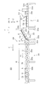
- FIG. 17 is a schematic perspective view showing an example of a bonding apparatus 200 used in a bonding process for bonding the solar cell module main body 11 and the support rail 12.
- FIG. 18 is a schematic side view showing the bonding apparatus 200 shown in FIG. In FIG. 18, the support member 230, the holding member 240, and the like are not shown.
- the bonding apparatus 200 is provided with an adhesive member in which an adhesive member (here, adhesive B) is provided on an adhesive surface of a member (solar cell module main body 11 or support rail 12, in this example, the solar cell module main body 11) to be provided with an adhesive member.
- the adhesive member disposing device here, the applicator 210) used in the process (here, the applying step) and the adhesive surface (here, the solar cell module body 11) of the member provided with the adhesive member (here, the adhesive B)
- a bonding device 220 used in a bonding process for bonding the back surface 11g) and the bonding surface of the mating member (here, the outer surface of the main plate 12a in the support rail 12).
- the adhesive member is the adhesive B
- the adhesive member disposing step is the application step
- the adhesive surface of the member to which the adhesive B is to be applied is the back surface of the solar cell module body 11.
- the coating device 210 applies the adhesive B to the back surface 11g of the solar cell module body 11, and in this embodiment, the solar cell module body 11 and a nozzle 213a (an example of an adhesive member discharge port) to be described later.
- the adhesive B is applied while relatively moving at least one (here, the solar cell module body 11).
- the coating apparatus 210 includes an application unit 210a that applies the adhesive B, an application table 210b, and a moving unit 210c.
- the application unit 210a includes an adhesive container 211, an adhesive supply unit 212, and an adhesive discharge unit 213.
- the adhesive storage unit 211 has a storage tank 211a for storing the adhesive B.
- a two-component silicone adhesive is used as the adhesive B, and the storage tank 211a includes a first tank 211b that stores the first bonding material and a second tank that stores the second bonding material. 2 tanks 211c.
- the adhesive supply unit 212 supplies the adhesive B stored in the adhesive storage unit 211 to the adhesive discharge unit 213.
- the adhesive supply unit 212 supplies the first adhesive material from the first tank 211b to the adhesive discharge unit 213, and the second adhesive material from the second tank 211c. By supplying to 213, these adhesive materials are mixed in the adhesive discharge section 213.
- the adhesive discharge unit 213 has a nozzle 213a that discharges the adhesive B.
- the number of nozzles 213a is one for one support rail 12.
- the application part 210a shall be the thing in which the adhesive agent accommodating part 211, the adhesive supply part 212, and the adhesive discharge part 213 were integrally formed, and the number of the support rails 12 (two in this example).
- the support members 230 and 230 are disposed on both sides in the direction (here, the vertical direction N) along the back surface 11g of the solar cell module body 11 orthogonal to the transport direction C.
- the holding member 240 has a long shape and is supported in a state of being stretched over the support members 230 and 230 along the vertical direction N.
- the coating table 210b is for mounting the solar cell module body 11 as a member to which the adhesive B is to be applied, and the moving unit 210c has at least one of the coating table 210b and the nozzle 213a (here, the coating table 210b). It is moved in the conveyance direction C.
- a coating stand 210 b and a moving unit 210 c are configured by the coating transport roller unit 214. That is, the application conveyance roller unit 214 has both functions of the application table 210b and the moving unit 210c.
- the application conveyance roller unit 214 has a length longer than twice the width H (see FIG. 18) in the lateral direction T of the solar cell module body 11, and follows the solar cell module body 11 coated with the adhesive B. It is conveyed to the bonding apparatus 220 in the bonding process.
- the application transport roller unit 214 includes a plurality of mounting rollers 214a to 214a arranged in parallel along the horizontal direction T so as to be parallel to the vertical direction N, and both end portions of the mounting rollers 214a to 214a in the vertical direction N. And a pair of support frames 214b and 214b for rotatably supporting the frame.
- the mounting rollers 214a to 214a are about the length in the vertical direction N of the solar cell module body 11. Further, the placement rollers 214a to 214a are set to the respective pitches P (see FIG. 18) that do not contact each other.
- each of the mounting rollers 214a to 214a has a pitch P of half or less of the width H in the lateral direction T of the solar cell module body 11, and the number of the solar cell module bodies 11 is 3 or more (here, 5).
- These mounting rollers 214a to 214a are used for support.
- the pair of support frames 214b and 214b is a long member that extends in the horizontal direction T and is disposed in parallel with both sides of the vertical direction N.
- a plurality of bearings 214c to 214c arranged in a row are provided.
- the mounting rollers 214a to 214a are rotatably supported with respect to the pair of support frames 214b and 214b, with the rotation shafts at both ends supported by the bearings 214c to 214c of the pair of support frames 214b and 214b, respectively. It is like that.
- the coating / conveying roller unit 214 reciprocates in the lateral direction T (adhesion) when the mounting rollers 214a to 214a rotate while the solar cell module body 11 is mounted on the mounting rollers 214a to 214a.
- the agent B When the agent B is applied, it can be moved in the transport direction C).
- the application transport roller unit 214 is configured to perform the transport operation of the solar cell module body 11 by an operator's manual work.
- the present invention is not limited to this, and the coating / conveying roller unit 214 may automatically perform the conveying operation of the solar cell module body 11 using a driving device.
- the bonding apparatus 220 bonds the back surface 11g of the solar cell module body 11 and the adhesive surface 12g of the support rail 12 via the adhesive B, and in this embodiment, the adhesive B is applied to the back surface 11g.
- the solar cell module body 11 is placed on the adhesive surface 12g of the support rail 12 on which the solar cell module body 11 has been placed in advance with the back surface 11g of the solar cell module body 11 facing down.
- the bonding apparatus 220 includes a first bonding / conveying roller unit 221 and a mounting table 222 (here, a second bonding / conveying roller unit).
- the first bonding / conveying roller unit 221 has a rear side (coating device 210 side) with respect to the front side (mounting table 222 side) of the solar cell module body 11 conveyed from the bonding / conveying roller unit 214 in the coating device 210. It is set as the structure which inclines the solar cell module main body 11 around the axis line along the vertical direction N so that it may become high.
- the first laminating and conveying roller portion 221 has a length of about the width H in the lateral direction T of the solar cell module body 11 and is inclined toward the mounting table 222 side. Thereby, in order to bond the solar cell module main body 11 with the support rail 12 by the next mounting base 222, it can be set as the attitude
- the first laminating and conveying roller unit 221 includes a plurality of mounting rollers 221a to 221a arranged in parallel along the horizontal direction T so as to be parallel to each other in the vertical direction N, and the vertical direction N of the mounting rollers 221a to 221a.
- a pair of support frames 221b and 221b that rotatably support both ends thereof, and a swinging part 221d that swings the pair of support frames 221b and 221b about an axis along the vertical direction N.
- the mounting rollers 221a to 221a are about the length in the vertical direction N of the solar cell module body 11. Further, the placement rollers 221a to 221a have pitches P (see FIG. 18) that do not contact each other. Here, each of the placement rollers 221a to 221a has a pitch P of half or less of the width H in the lateral direction T of the solar cell module body 11, and the number of the solar cell module bodies 11 is 3 or more (here, 5). These mounting rollers 221a to 221a are used for support.
- the pair of support frames 221b and 221b are long members that extend in the horizontal direction T and are arranged in parallel on both sides of the vertical direction N, and 1 along the horizontal direction T inside the vertical direction N.
- a plurality of bearings 221c to 221c arranged in a row are provided.
- the mounting rollers 221a to 221a are rotatably supported with respect to the pair of support frames 221b and 221b by the rotation shafts at both ends being supported by the bearings 221c to 221c of the pair of support frames 221b and 221b, respectively. It is like that.
- the swinging portion 221d supports the rotation shaft 221f along the vertical direction N inserted through the through holes 221e provided at the front ends of the pair of support frames 221b and 221b, the rotation shaft 221f, and A pair of support frames 221b, 221b has a mounting portion 221g for mounting the rear end portion.
- the first laminating and conveying roller unit 221 can be inclined so that the rear side becomes higher in a state where the solar cell module body 11 is placed on the placement rollers 221a to 221a.
- the first bonding transport roller unit 221 is configured to perform the transport operation and the tilting operation of the solar cell module body 11 by an operator's manual work.
- the present invention is not limited to this, and the first bonding transport roller unit 221 may be configured such that the transport operation and / or the tilting operation of the solar cell module body 11 is automatically performed using the driving device. Good.
- the mounting table 222 is configured to mount the support rail 12 as a mating member to be bonded so that the adhesive surface 12g faces upward.
- the configuration of the mounting roller 222a, the support frame 222b, the bearing 222c, and the like in the mounting table 222 shown in FIGS. 17 and 18 will be described in detail later.
- the mounting table 222 has a length longer than the length d1 of the support rail 12 (see FIG. 18), and is a subunit in which the support rail 12 and the solar cell module body 11 are bonded together with an adhesive B. 10 is conveyed to the next curing process.
- the curing step is a step of curing the adhesive B so that the adhesive strength of the adhesive B can be sufficiently obtained.
- FIG. 19 is a schematic side view showing a bonding process between the solar cell module main body 11 and the support rails 12 and 12 using the bonding apparatus 200 shown in FIGS. 17 and 18.
- FIG. 19A is a diagram illustrating an application process of applying the adhesive B to the back surface 11g of the solar cell module body 11, and FIG. 19B illustrates the back surface 11g of the solar cell module body 11 and the support rails 12,
- FIG. 19C is a diagram showing a state before the solar cell module body 11 and the support rails 12 and 12 are bonded together in the bonding step of bonding the film 12 with the adhesive B through the adhesive B.
- FIG. It is a figure which shows the state after bonding the solar cell module main body 11 and the support rails 12 and 12 in the bonding process shown to).
- FIG. 20 shows a case where the adhesive surface 12g of the support rail 12 mounted on the mounting table 222 and the back surface 11g of the solar cell module body 11 are bonded together with an adhesive B with the adhesive surface 12g facing upward.
- the adhesive B is applied to the back surface 11g of the solar cell module body 11.
- the solar cell module body 11 to which the adhesive B is applied is conveyed to the first bonding conveyance roller unit 221 in the next bonding process.
- the adhesive B is used as the adhesive member.
- the long double-sided PSA sheet is placed in the lateral direction T of the solar cell module body 11. You may make it adhere
- the bonding step prior to bonding the back surface 11g of the solar cell module body 11 and the support rails 12 and 12, bonding is performed on the mounting rollers 222a to 222a in the mounting table 222.
- the support rails 12 and 12 are placed in advance with the surface 12g (specifically, the main plate 12a) facing up.
- the solar cell module body 11 conveyed from the coating process is inclined by the first bonding / conveying roller unit 221 so that the back surface 11g coated with the adhesive B can be easily turned over.
- the support rail 12 is placed on the mounting table 222 with the adhesive surface 12g of the support rail 12 facing up, and the adhesive surface 12g of the support rail 12 placed on the mounting table 222 and the back surface of the solar cell module body 11
- the solar cell module body 11 is warped upward on the side opposite to the support rail 12 as it goes from the center portion E1 to both end portions E2 and E3 in the warp direction K by bonding 11g with the adhesive B. (See FIG. 20), a stable posture that minimizes the distance F at which the solar cell module body 11 is farthest between the solar cell module body 11 and the support rail 12 (in this example, the center in the warp direction K).
- the portion E1 is easy to fit in the position closest to the support rail 12), and the solar cell module body 11 and the support rail 12 can be securely bonded to that extent. Can.
- the solar cell module body 11 is placed in a state close to the environment where the subunit 10 is actually installed.
- the sub-unit 10 when the sub-unit 10 is actually installed by bonding with the light receiving surface (specifically, the light receiving surface glass 11b) of the solar cell module body 11 down, the solar cell module body 11 Compared with the case where the light receiving surface of the sub-unit 10 is faced up, the posture of the sub-unit 10 is changed between when the adhesive B is cured in the sub-unit 10 and when the sub-unit 10 is cured with the adhesive B. The stress applied to the adhesive B can be reduced, and the burden on the adhesive B can be reduced accordingly.
- the light receiving surface specifically, the light receiving surface glass 11b
- a load may be applied to the back surface 11g of the solar cell module body 11 when the back surface 11g of the solar cell module body 11 is bonded to the bonding surface 12g of the support rail 12.
- the back surface 11g of the solar cell module body 11 is bonded to the bonding surface 12g of the support rail 12 by its own weight without applying a load to the back surface 11g of the module body 11.
- the adhesive B is pressed by the own weight of the solar cell module body 11 (for example, about 156.99064N: about 16 kgf), and the back surface 11g of the solar cell module body 11 and the adhesive surface 12g of the support rails 12 and 12 are brought together. Adhere.
- the back surface 11g of the solar cell module main body 11 is bonded to the bonding surface 12g of the support rails 12 and 12 by the own weight of the solar cell module main body 11, so that the solar cell module main body 11 is self-weighted.
- 11 can be easily and easily placed in a stable posture (in this example, the center portion E1 in the warp direction K is closest to the support rail 12).
- the mounting table 222 is a virtual plane that connects the mounting positions of the solar cell module main body 11 (specifically, the apexes of the portions of the mounting rollers 222a to 222a on which the solar cell module main body 11 is mounted). ) Is horizontal or substantially horizontal.
- the adhesive surface 12g of the support rail 12 is placed horizontally or substantially horizontally with respect to the placement position of the placement table 222 that is horizontal or substantially horizontal.
- the solar cell module main body 11 is maintained in a state where the horizontal or substantially horizontal posture of the solar cell module main body 11 is maintained by placing the adhesive surface 12g of the support rail 12 horizontally or substantially horizontally on the mounting table 222. 11 can be stably adhered.
- the solar cell module body 11 having the warping direction K as the longitudinal direction L (left-right direction X) of the support rail 12 and warping in the longitudinal direction L is bonded.
- the adhesion failure which occurs easily when the solar cell module main body 11 warped in the longitudinal direction L is bonded that is, as shown in FIGS. 15 and 16, the distance between the support rail 12 and the solar cell module main body 11). It is possible to reliably suppress the adhesion failure in which the support rail 12 is lifted from the solar cell module body 11 without F being separated and being bonded via the adhesive B.
- the solar cell module main body 11 is bonded so as to be arranged in a plurality in the longitudinal direction L (left-right direction X) of the long support rail 12.
- the adhesion failure that is likely to occur when the solar cell module body 11 is bonded in a plurality in the longitudinal direction L (left-right direction X) of the support rail 12 (that is, as shown in FIG. 16, the support rail 12 and the solar cell module main body 11 are separated from each other by a distance F and the support rail 12 is not adhered via the adhesive B, and the support rail 12 is lifted from the solar cell module main body 11. .
- the support rail 12 and the solar cell module main body 11 are placed between the adjacent solar cell module main bodies 11 and 11 with a spacer SP (see FIG. 19C, FIG. 20 and FIG. 28 described later). Paste together in an intervening state.
- the adjacent solar cell module main bodies 11 and 11 are bonded together by bonding the support rail 12 and the solar cell module main body 11 with the spacer SP interposed between the adjacent solar cell module main bodies 11 and 11. It becomes possible to ensure the space
- damage to the solar cell module main bodies 11 and 11 due to collision between adjacent solar cell module main bodies 11 and 11 can be suppressed, and another solar cell module main body 11 is placed next to one solar cell module main body 11.
- the impact between the adjacent solar cell module bodies 11 and 11 can be reduced by the spacers SP, so that the collision between the adjacent solar cell module bodies 11 and 11 is taken into consideration.
- the solar cell module body 11 can be bonded to the support rail 12, and the bonding workability can be improved accordingly.
- the spacer SP may be a single elongate member extending along the vertical direction N of the solar cell module body 11, or a cylindrical or rectangular parallelepiped member is spaced along the vertical direction N. A plurality of them may be arranged.
- an elastic material such as polyurethane foam, acrylic foam, or urethane can be used.
- the spacer SP is provided in advance on at least one adjacent side of the bonded solar cell module main body 11 and the solar cell module main body 11 to be bonded next thereto, and is adjacent to the bonded solar cell module main body 11.
- the solar cell module main body 11 to be bonded can be bonded to the spacer SP.
- the spacer SP may be removed after the adhesive B between the solar cell module body 11 and the support rails 12 and 12 is cured, or may be left.
- the spacer SP may be bonded to at least one adjacent side of the bonded solar cell module body 11 and the adjacent solar cell module body 11 bonded thereto. Adhesion between the spacer SP and the solar cell module body 11 can be performed by an adhesive member such as an acrylic adhesive, a urethane adhesive, or a butyl tape. Further, when the spacer SP is provided without being bonded, the spacer SP can be easily removed after the adhesive B is cured.
- the support rail 12 placed on the placement table 222 is positioned on the placement table 222 by a support rail positioning unit 250 (an example of a support member positioning unit, see FIG. 21 described later).
- the adhesive surface 12g of the support rail 12 and the back surface 11g of the solar cell module body 11 are bonded together with an adhesive B. That is, the mounting table 222 is mounted in a state where the support rail 12 is positioned at a position where the support rail 12 is bonded to the solar cell module body 11.
- FIG. 21 is a schematic perspective view showing an example of the mounting table 222.
- FIG. 22 is a schematic side view of the mounting table 222 shown in FIG.
- FIG. 23 is a schematic cross-sectional view along the line GG of the mounting table 222 shown in FIG.
- FIG. 24 is a schematic perspective view showing the switching device 253 for switching between the protruding position and the retracted position of the second support rail positioning portion 252.
- FIG. FIG. 25 is an enlarged schematic cross-sectional view showing an end portion on the downstream side in the transport direction C of the mounting table 222.
- FIG. 25A shows a state where the second support rail positioning portion 252 is located at the protruding position
- FIG. 25B shows that the second support rail positioning portion 252 is located at the retracted position. It shows the state.
- FIG. 26 is a schematic perspective view of an end of the mounting table 222 on the downstream side in the conveyance direction C as viewed obliquely from the center in the width direction M toward the outside
- the second support rail positioning part 252, the second solar cell module positioning part 262, the switching device 253, and the like are not shown.
- 25 and 26 show the downstream end of the mounting table 222 in the transport direction C, but the upstream end of the mounting table 222 in the transport direction C has the same configuration. However, illustration is abbreviate
- FIG. 26 one end portion in the width direction M of the mounting table 222 is shown, but the other end portion in the width direction M of the mounting table 222 has the same configuration, and is not shown here.
- the support rail 12 and the solar cell module main body 11 are shown in cross section.
- the bonding apparatus 200 includes a support rail positioning portion 250 for positioning the support rail 12.
- the bonding surface 12 g of the support rail 12 placed on the mounting table 222 and positioned by the support rail positioning portion 250 and the solar cell module main body. 11 is bonded to the back surface 11g via an adhesive B.
- the bonding surface 12g of the support rail 12 and the back surface 11g of the solar cell module body 11 which are mounted on the mounting table 222 and positioned on the mounting table 222 by the support rail positioning unit 250. Can be bonded in a state where the solar cell module body 11 and the support rail 12 are accurately aligned. Therefore, when the subunit 10 is actually installed, it is possible to install the subunit 10 in a state in which the subunit 10 is accurately aligned with respect to the gantry 20 that is positioned and fixed to install the subunit 10.
- the long support rail when the solar cell module body 11 is bonded in a plurality in the longitudinal direction L (left and right direction X) of the long support rail 12 as in the present embodiment, the long support rail Thus, it is possible to reliably suppress positioning defects that are likely to occur when a plurality of solar cell module main bodies 11 to 11 are bonded to 12.
- the mounting table 222 includes a mounting roller 222a (an example of a transport roller) that acts as a transport member that mounts the support rail 12 and transports the support rail 12 in a predetermined transport direction C.
- the mounting roller 222a includes a plurality of mounting rollers 222a to 222a arranged in parallel in the transport direction C so that the direction of the rotation axis is along the width direction M orthogonal to both the vertical direction Z and the transport direction C. Has been.
- the mounting table 222 includes a plurality of mounting rollers 222a to 222a arranged in parallel along the horizontal direction T so as to be parallel to the vertical direction N, and the vertical direction N of the mounting rollers 222a to 222a. And a pair of support frames 222b and 2222b for rotatably supporting both ends of the frame.
- the mounting rollers 222a to 222a are about the length of the solar cell module body 11 in the vertical direction N. Further, the placement rollers 222a to 222a have respective pitches P1 (see FIG. 18) at which first solar cell module body positioning portions 261 described later do not contact each other.
- each of the mounting rollers 222a to 222a has a pitch P1 of half or less of the width H in the lateral direction T of the solar cell module body 11, and three or more support rails 12 per solar cell module body 11. It is supported by (here, three) mounting rollers 221a to 221a.
- the pair of support frames 222b and 222b is a long member that extends in the horizontal direction T and is disposed in parallel on both sides in the vertical direction N, and is 1 along the horizontal direction T inside the vertical direction N.
- a plurality of bearings 222c to 222c arranged in a row are provided.
- the mounting rollers 222a to 222a are supported by the pair of support frames 222b and 222b by supporting the rotation shafts 222a1 and 222a1 (see FIG. 23) at both ends by the bearings 222c to 222c of the pair of support frames 222b and 222b, respectively. On the other hand, it is supported rotatably.
- the support rail positioning portion 250 is provided on the mounting table 222 and restricts the movement of the support rail 12 in the width direction M (an example of a first support member positioning portion, FIG. 21). To FIG. 23). According to this configuration, the support rail 12 can be easily positioned in the width direction M by the first support rail positioning portion 251.
- the first support rail positioning portion 251 has a restriction groove 251a (see FIGS. 22, 23, 25, and 26) that restricts the movement of the support rail 12 in the width direction M. .
- the support rail 12 can be reliably positioned in the width direction M while being a simple and inexpensive configuration of the restriction groove 251a.
- the restriction groove 251a is provided over the entire circumferential direction of the placement rollers 222a to 222a at the position where the support rail 12 is placed in the rotation axis direction of the placement rollers 222a to 222a.
- the regulation groove 251a has a depth h1 (see FIG. 23) smaller than the height t1 (see FIG. 23) of the support rail 12 with the adhesive surface 12g facing up.
- the size in the width direction M of the regulation groove 251a can slide to the upstream side and the downstream side in the conveyance direction C of the support rail 12 (specifically, the support rail 12 is moved into the regulation groove 251a by the mounting rollers 222a to 222a. It can be conveyed while being slidably contacted) (approximately the dimension in the width direction M of the support rail 12).
- the support rail positioning unit 250 is provided on the mounting table 222 and regulates the movement of the support rail 12 in the upstream direction and the downstream direction in the transport direction C.
- 252 (an example of a second support member positioning portion) is further included.
- the second support rail positioning unit 252 can easily position the support rail 12 in the upstream direction and the downstream direction in the transport direction C.
- the second support rail positioning portion 252 is a plate-like member.
- the second support rail positioning portion 252 has a restriction surface 252a (see FIGS. 24 and 25) for restricting the position of the support rail 12.
- the dimension of the second support rail positioning portion 252 in the width direction M is set to a value approximately equal to or larger than the dimension of the support rail 12 in the width direction M.
- the second support rail positioning portion 252 is configured so that the mounting position of the support rail 12 in the vertical direction Z of the mounting table 222 (specifically, the position of the bottom surface of the restriction groove 251a, the lower end position of the support rail 12) 222d ( It is possible to switch between a projecting position projecting upward from the projecting position and a retracted position retracting from the projecting position to the mounting position 222d or the mounting position 222d.
- the bonding apparatus 200 moves the support rail 12 in the transport direction C by the second support member positioning unit 252 when the second support rail positioning unit 252 is positioned at the protruding position (see FIG. 25A). Can be positioned in the upstream direction and the downstream direction.
- the bonding apparatus 200 moves the support rail 12 (specifically, the support rail 12 and the solar cell module) when the second support rail positioning portion 252 is positioned at the retracted position (see FIG. 25B).
- the subunit 10 bonded to the main body 11 can be transported in the transport direction C) by the mounting rollers 222a to 222a toward the next curing step.
- the bonding apparatus 200 includes a switching device 253 (see FIGS. 21, 24, and 25) that switches between a protruding position and a retracted position of the second support rail positioning portion 252.
- the switching device 253 includes a holding unit 2531 (see FIG. 24) that holds the second support rail positioning unit 252 and an actuator 2532 (see FIG. 24) that operates the holding unit 2531.
- the holding portion 2531 has a U-shaped holding portion 2531a in a side view.
- the holding portion 2531a holds the lower end portion of the second support rail positioning portion 252 and is connected to the movable portion 2532a of the actuator 2532. It has become so.
- the actuator 2532 is an air cylinder, and the movable portion 2532a, which is a piston, is reciprocated in the vertical direction Z using compressed air from the compressor 2532c.
- the compressor 2532c is connected to the air cylinder body 2532b.
- the raising / lowering operation of the movable part 2532a by the compressed air from the compressor 2532c is performed by operating the raising operation part 2532d for raising the movable part 2532a and the lowering operation part 2532e for lowering the movable part 2532a (for example, by manual operation by an operator). Specifically, it is performed by the operator's foot operation).
- the actuator 2532 is fixed to the main body 220a (see FIG. 21) of the bonding apparatus 220.
- FIG. 24 shows one switching device 253, but each switching device 253 to 253 shown in FIG. 21 has the same configuration, and the other switching devices 253 are the switching devices shown in FIG.
- the device 253 is shown as a representative.
- the respective movable portions 2532a to 2532a are simultaneously lifted when the raising operation portion 2532d is operated, while the respective movable portions 2532a are moved when the lowering operation portion 2532e is operated. ⁇ 2532a descend at the same time.
- the distance between the second support rail positioning portions 252 and 252 in the switching devices 253 and 253 facing each other in the transport direction C is such that the support rail 12 can be inserted while being in sliding contact with the second support rail positioning portions 252 and 252.
- the distance is approximately the length d1 of the support rail 12 (see FIG. 22).
- the movable portion 2532a is lifted by operating the lifting operation portion 2532d, and accordingly, the second support rail positioning portion 252 is in the protruding position (see FIG. 25A). ). Accordingly, the support rail 12 can be positioned in the upstream direction and the downstream direction in the transport direction C by the second support rail positioning unit 252.
- the movable portion 2532a is lowered, and accordingly, the second support rail positioning portion 252 is positioned at the retracted position (see FIG. 25B). Accordingly, the subunit 10 in which the support rail 12 and the solar cell module body 11 are bonded to each other can be transported in the transport direction C toward the next curing process by the mounting rollers 222a to 222a.
- the solar cell module body positioning portion is bonded to the adhesive surface 12g of the support rail 12 mounted on the mounting table 222 and the back surface 11g of the solar cell module body 11 via the adhesive B.
- the solar cell module body 11 is bonded while being positioned by 260.
- the bonding apparatus 200 further includes a solar cell module main body positioning portion 260 for positioning the solar cell module main body 11, and includes an adhesive surface 12g of the support rail 12 mounted on the mounting table 222 and a back surface 11g of the solar cell module main body 11.
- the solar cell module main body 11 is bonded together while positioning the solar cell module main body 11 by the solar cell module main body positioning portion 260 via the adhesive B.
- the solar cell module main body positioning between the adhesive surface 12g of the support rail 12 mounted on the mounting table 222 and the rear surface 11g of the solar cell module main body 11 via the adhesive B.
- the solar cell module body 11 and the support rail 12 can be bonded in a state of being accurately aligned. Therefore, when the subunit 10 is actually installed, it is possible to install the subunit 10 in a state in which the subunit 10 is accurately aligned with respect to the gantry 20 that is positioned and fixed to install the subunit 10.
- the long support rail when the solar cell module body 11 is bonded in a plurality in the longitudinal direction L (left and right direction X) of the long support rail 12 as in the present embodiment, the long support rail Thus, it is possible to reliably suppress positioning defects that are likely to occur when a plurality of solar cell module main bodies 11 to 11 are bonded to 12.
- the solar cell module main body positioning unit 260 is provided on the mounting table 222 and regulates the movement of the solar cell module main body 11 in the width direction M (see FIG. 21). To FIG. 23 and FIG. 25 and FIG. 26). According to this configuration, the solar cell module main body 11 can be easily positioned in the width direction M by the first solar cell module main body positioning portion 261.
- the first solar cell module main body positioning portion 261 is provided so as to protrude in the radial direction of the mounting rollers 222a to 222a at both ends in the rotational axis direction of the mounting rollers 222a to 222a and to extend in the width direction M.
- a protrusion 261a (see FIGS. 23 and 26) that restricts the movement of the solar cell module body 11 is provided. According to such a configuration, the solar cell module body 11 can be reliably positioned in the width direction M while being a simple and inexpensive configuration of the protruding portion 261a.
- the protruding portion 261a is provided over the entire circumferential direction of the mounting rollers 222a to 222a at both ends in the rotational axis direction of the mounting rollers 222a to 222a.
- the protrusion 261a has an outer diameter larger than the outer diameter of the placement roller 222a, and has a disk shape centered on the rotation axis of the placement roller 222a.
- the protruding portion 261a has a lower end position of the solar cell module body 11 in which the height h2 (see FIG. 23) for regulating the solar cell module body 11 in the width direction M is arranged on the support rail 12 via the adhesive B.
- the height is greater than the height t2 (see FIG. 23).
- the distance between the first solar cell module main body positioning portions 261 and 261 facing each other in the width direction M is inserted while the solar cell module main body 11 is in sliding contact with the first solar cell module main body positioning portions 261 and 261.
- the distance is as long as possible (the length d4 in the vertical direction N of the solar cell module body 11 (see FIG. 23)).
- the projecting portion 261a has a guide portion 261b (see FIGS. 23 and 26) that is provided on the outer peripheral portion and the height in the radial direction increases toward the outside in the width direction M.
- the guide portion 261b has an inclined surface 261c (see FIGS. 23 and 26) that is inclined so as to increase in the width direction M as it goes outward.
- the projecting portion 261a includes the guide portion 261b, the solar cell module body 11 is reliably guided between the first solar cell module body positioning portions 261 and 261 facing each other by the guide portion 261b.
- the solar cell module main body 11 can be easily inserted between the first solar cell module main body positioning portions 261 and 261.
- the protruding portion 261a and the guide portion 261b are integrally formed.
- the solar cell module main body positioning unit 260 is provided on the mounting table 222 and regulates the movement of the solar cell module main body 11 in the upstream direction and the downstream direction in the transport direction C. 2 It further has the positioning part 262 for solar cell module main bodies (refer FIG.21, FIG.22, FIG.24 and FIG. 25). According to this configuration, the solar cell module main body 11 can be easily positioned on the upstream side and the downstream side in the transport direction C by the second solar cell module main body positioning unit 262.
- the second solar cell module main body positioning portion 262 has a regulating surface 262a (see FIGS. 24 and 25) that regulates the position of the solar cell module main body 11.
- a switching device such as the switching device 253 may be provided separately, and the second solar cell module main body positioning unit 262 may be provided in the switching device, but here, the second solar cell module main body positioning unit 262 is provided.
- 24 and 25 are provided in the second support rail positioning portion 252 held by the switching device 253.
- the second solar cell is placed in the second support rail positioning portion 252.
- the second support rail positioning unit 252 can also be used as the second solar cell module main body positioning unit 262.
- the second solar cell module body positioning portion 262 is above the bonding position of the solar cell module body 11 in the vertical direction Z of the support rail 12 (specifically, the position of the lower end of the solar cell module body 11).
- the mounting position of the support rail 12 in the vertical direction Z of the mounting table 222 (specifically, the position of the bottom surface of the restriction groove 251a, the lower end position of the support rail 12) 222d or the mounting position from the protruding position It is possible to switch to a retreat position that retreats below 222d.
- the switching device 253 is used for the switching operation between the protruding position and the retracted position of the second solar cell module body positioning portion 262.
- the bonding apparatus 200 has the second solar cell module main body positioning portion 262.
- the solar cell module body 11 can be positioned in the upstream direction and the downstream direction in the transport direction C.
- the bonding apparatus 200 supports the support rail 12 (specifically, the support rail 12).
- the subunit 10 to which the rail 12 and the solar cell module body 11 are bonded can be transported in the transport direction C) by the mounting rollers 222a to 222a (toward the next curing step).
- the second solar cell module main body positioning portion 262 is a restricting protrusion provided on the upper portion of the second support rail positioning portion 252.
- the second solar cell module positioning unit 262 has an upper end that is flush with the upper end of the second support rail positioning unit 252 in the vertical direction Z (same position) or lower than the upper end of the second support rail positioning unit 252. It is considered as a position. By doing so, when the second support rail positioning part 252 is retracted to the retracted position, the second solar cell module body positioning part 262 can also be retracted to the retracted position.
- the movable portion 2532a is lifted by operating the lifting operation portion 2532d, and accordingly, the second support rail positioning portion 252 is in the protruding position (see FIG. 25A). ),
- the solar cell module main body 11 can be positioned in the upstream direction and the downstream direction in the transport direction C by the second solar cell module main body positioning portion 262.
- the operation unit for lowering 2532e is operated, the movable unit 2532a is lowered, and accordingly, the second support rail positioning unit 252 is positioned at the retracted position (see FIG. 25B).
- the subunit 10 in which the support rail 12 and the solar cell module body 11 are bonded can be transported in the transport direction C toward the next curing process by the mounting rollers 222a to 222a.
- the second solar cell module body positioning portion 262 is wider than the support rail 12 so as not to collide with the support rail 12 when the second support rail positioning portion 252 is retracted to the retracted position.
- the pair is provided outside the direction M.
- the dimension between the pair of second solar cell module main body positioning portions 262 and 262 in the width direction M is approximately the same as the dimension in the width direction M of the support rail 12 or the dimension in the width direction M of the support rail 12. The dimensions are large.
- the second support rail positioning part 252 is By extending the second solar cell module main body positioning portion 262 to a position overlapping the lower support rail 12 in the state where the second solar cell module main body positioning portion 262 is located at the protruding position,
- the first support rail positioning portion 251 can be provided with a function (a mechanism for restricting movement of the support rail 12 in the width direction M).
- the mounting table 222 is configured to perform a transport operation, a bonding operation, and an alignment operation of the solar cell module body 11 by an operator's manual operation.
- the mounting table 222 is not limited thereto, and at least one of the transporting operation, the bonding operation, and the alignment operation of the solar cell module body 11 is automatically performed using the driving device. May be.
- the adhesive B is applied to the back surface 11g of the solar cell module body 11, but instead of or in addition, the adhesive B may be applied to the adhesive surface 12g of the support rails 12 and 12.
- FIG. 27 is a schematic perspective view illustrating another example of the bonding apparatus 200 illustrated in FIGS. 17 to 19, in which an adhesive B is applied to the bonding surfaces 12 g of the support rails 12 and 12.
- the adhesive device 200 shown in FIG. 27 is the same as the adhesive device 200 shown in FIGS. 17 to 19, except that the first bonding and conveying roller unit 221 is removed, and a mounting table 222 is provided instead of the coating and conveying roller unit 214.
- the nozzle 213a in the coating section 210a is moved from the upstream side in the transport direction C to the downstream side or from the downstream side to the upstream side by the support member 230 supported by the moving rails 231 and 231 so as to reciprocate in the upstream and downstream sides in the transport direction C.
- the adhesive B is applied to the adhesive surface 12g of the support rails 12 and 12 positioned on the mounting table 222.
- the first bonding transport roller section 221 and the coating transport roller section 214 are removed in the bonding apparatus 200 shown in FIGS.
- the configuration can be simplified, and the overall length in the transport direction C can be shortened, and the work space can be reduced accordingly.
- FIG. 28 is a schematic perspective view showing a state of the subunit 10 obtained by bonding the solar cell module body 11 on the support rails 12 and 12 by the bonding apparatus 200 shown in FIGS. 17 to 19 and 27.
- two support rails 12 and 12 and three solar cell module bodies 11 are bonded to each other as a subunit 10 via an adhesive B. Is obtained, the obtained subunit 10 is conveyed to the next curing step by the placement roller 222a in the placement table 222.
- the present invention is useful in a method for manufacturing a solar cell module in which the back surface of the solar cell module main body and the adhesion surface of the support member to the solar cell module main body are bonded via an adhesive member, and the solar cell module main body is warped. Even in this case, the present invention can be applied to a photovoltaic power generation system in which it is essential to securely bond the solar cell module body and the support member.
- Sub unit an example of a solar cell module
- Solar cell module body 11c Back glass 11g Back 12
- Support rail an example of a support member 12
- Bonding surface 200 Bonding device 210 Coating device 220 Bonding device 221 First bonding conveying roller portion 221a Mounting roller 221b Support frame 221c Bearing 221d Oscillating portion 221e Through hole 221f Rotating shaft 221g Mounting portion 222 Mounting table 222a Mounting Roller (an example of a transport roller) 222b Support frame 222c Bearing 222d Placement position 250 Support rail positioning part (an example of a support member positioning part) 251 First support rail positioning part (an example of a first support member positioning part) 251a Restriction groove 252 Second support rail positioning part (an example of a second support member positioning part) 253 Switching device 260
- Solar cell module main body positioning part 261 First solar cell module main body positioning part 261a Projection part 262
- Second solar cell module main body positioning part A Photovoltaic power generation system B
Landscapes
- Engineering & Computer Science (AREA)
- Physics & Mathematics (AREA)
- Life Sciences & Earth Sciences (AREA)
- Sustainable Development (AREA)
- Sustainable Energy (AREA)
- Thermal Sciences (AREA)
- Chemical & Material Sciences (AREA)
- Combustion & Propulsion (AREA)
- Mechanical Engineering (AREA)
- General Engineering & Computer Science (AREA)
- Photovoltaic Devices (AREA)
Abstract
太陽電池モジュール本体の裏面とサポート部材の前記太陽電池モジュール本体に対する接着面とを接着部材を介して接着させる太陽電池モジュールの製造方法であって、前記サポート部材の前記接着面を上にして前記サポート部材を載置台に載置する工程と、前記載置台に載置された前記サポート部材の前記接着面と前記太陽電池モジュール本体の裏面とを前記接着部材を介して貼り合わせる工程とを含んでいる。
Description
本発明は、太陽電池モジュール本体の裏面とサポート部材の前記太陽電池モジュール本体に対する接着面とを接着部材を介して接着させる太陽電池モジュールの製造方法に関する。
太陽電池モジュール本体を備えた従来の太陽電池モジュールのなかには、太陽電池モジュールを設置するために、太陽電池モジュール本体の裏面とサポート部材(例えば長尺形状のサポート部材)の太陽電池モジュール本体に対する接着面とを接着部材を介して接着したものがある(例えば特許文献1参照)。
ところで、太陽電池モジュール本体は、例えば、受光面を構成する受光側部材(例えば受光面ガラス)上に、表面電極と、半導体層と、裏面電極とがこの順に積層されて太陽電池ストリングが形成され、裏面を構成する裏側部材(例えば裏面ガラスや裏面バックシート)が貼り合わされて、受光側部材及び裏側部材の両部材間が封止されることにより形成される。また、太陽電池モジュール本体を加熱しながら張り合わすこともある。
このような太陽電池モジュール本体では、受光側部材(例えば受光面ガラス)の厚みや材質等の物性、半導体層裏面を構成する裏側部材(例えば裏面ガラスや裏面バックシート)の厚みや材質等の物性、或いは、表面電極、半導体層や裏面電極の厚みや物性が異なることから、反りが発生することがある。このことは、太陽電池モジュール本体を加熱しながら張り合わす場合に特に顕著となる。
このように、太陽電池モジュール本体に反りが発生すると、太陽電池モジュール本体の裏面とサポート部材の太陽電池モジュール本体に対する接着面とを接着部材を介して接着させるときに、太陽電池モジュール本体の反りによって太陽電池モジュール本体とサポート部材とを確実に接着できない場合がある。
そこで、本発明は、太陽電池モジュール本体の裏面とサポート部材の太陽電池モジュール本体に対する接着面とを接着部材を介して接着させるときに、たとえ太陽電池モジュール本体が反っていたとしても太陽電池モジュール本体とサポート部材とを確実に接着させることができる太陽電池モジュールの製造方法を提供することを目的とする。
本発明者は、前記課題を解決するために、試行錯誤を重ねた結果、次のことを見出した。
すなわち、太陽電池モジュール本体の裏面とサポート部材の太陽電池モジュール本体に対する接着面とを接着部材を介して接着させるにあたって、例えば、太陽電池モジュール本体の裏面を上にして太陽電池モジュール本体を載置台に載置し、載置台に載置された太陽電池モジュール本体の裏面とサポート部材の接着面とを接着部材を介して貼り合わせる場合において、太陽電池モジュール本体が反っていると、サポート部材が太陽電池モジュール本体の反り方向に傾く傾斜姿勢になり易いために、サポート部材と、太陽電池モジュール本体の一部分とを接着部材を介して接着させても他の部分では、サポート部材と太陽電池モジュール本体との距離が接着部材の及ばない程度にまで離れてしまうことから、この部分で接着せずにサポート部材が太陽電池モジュール本体から浮いた状態となる接着不良が発生してしまう。このことは、サポート部材が長尺状の部材とされており、長尺状のサポート部材の長手方向に反った太陽電池モジュール本体を貼り合わせる場合、さらに言えば、太陽電池モジュール本体を長尺状のサポート部材の長手方向に複数に並ぶように貼り合わせる場合に特に顕著となる。
これに対して、サポート部材の接着面を上にしてサポート部材を載置台に載置し、載置台に載置されたサポート部材の接着面と太陽電池モジュール本体の裏面とを接着部材を介して貼り合わせると、太陽電池モジュール本体が反っていても、太陽電池モジュール本体が太陽電池モジュール本体とサポート部材との間で最も離れてしまう部分の距離を最小限に抑える安定姿勢(例えば、サポート部材とは反対側に反った状態の太陽電池モジュール本体においてサポート部材に対して離れる部分がサポート部材に最も近接する姿勢)に収まり易く、それだけ、太陽電池モジュール本体とサポート部材とを確実に接着させることができる。
本発明は、かかる知見に基づくものであり、太陽電池モジュール本体の裏面とサポート部材の前記太陽電池モジュール本体に対する接着面とを接着部材を介して接着させる太陽電池モジュールの製造方法であって、前記サポート部材の前記接着面を上にして前記サポート部材を載置台に載置する工程と、前記載置台に載置された前記サポート部材の前記接着面と前記太陽電池モジュール本体の裏面とを前記接着部材を介して貼り合わせる工程とを含むことを特徴とする太陽電池モジュールの製造方法を提供する。
本発明によれば、前記サポート部材の前記接着面を上にして前記サポート部材を載置台に載置し、前記載置台に載置された前記サポート部材の前記接着面と前記太陽電池モジュール本体の裏面とを前記接着部材を介して貼り合わせることで、たとえ前記太陽電池モジュール本体が反っていても、前記太陽電池モジュール本体が前記太陽電池モジュール本体と前記サポート部材との間で最も離れてしまう部分の距離を最小限に抑える安定姿勢に収まり易く、それだけ、前記太陽電池モジュール本体と前記サポート部材とを確実に接着させることができる。しかも、前記太陽電池モジュール本体の受光面を上にした状態で接着させるために、前記太陽電池モジュールを実際に設置する環境に近い状態で前記太陽電池モジュール本体を接着させることができ、前記太陽電池モジュールにおいて前記接着部材を硬化させた時と前記接着部材が硬化した前記太陽電池モジュールを設置した時とで前記太陽電池モジュールの姿勢が変化したことにより前記接着部材に加わる応力を小さくすることができ、それだけ前記接着部材にかかる負担を軽減させることが可能となる。
本発明において、前記サポート部材と前記太陽電池モジュール本体とを貼り合わせる工程では、前記サポート部材の前記接着面に対して前記太陽電池モジュール本体の裏面を前記太陽電池モジュール本体の自重で接着させる態様を例示できる。
この特定事項では、前記サポート部材の前記接着面に対して前記太陽電池モジュール本体の裏面を前記太陽電池モジュール本体の自重で接着させることで、前記太陽電池モジュール本体の自重により前記太陽電池モジュール本体が簡単にかつ容易に前記安定姿勢に収まるようにすることが可能となる。
本発明において、前記サポート部材を載置する工程では、前記サポート部材の前記接着面を前記載置台に水平又は略水平に載置する態様を例示できる。
この特定事項では、前記サポート部材の前記接着面を前記載置台に水平又は略水平に載置することで、前記太陽電池モジュール本体の水平方向又は略水平方向の姿勢を維持した状態で前記太陽電池モジュール本体を安定的に接着させることが可能となる。
本発明において、前記サポート部材は、長尺状の部材とされている態様を例示できる。この場合、前記サポート部材と前記太陽電池モジュール本体とを貼り合わせる工程では、長尺状の前記サポート部材の長手方向に反った前記太陽電池モジュール本体を貼り合わせる態様を例示できる。
この特定事項では、長尺状の前記サポート部材の長手方向に反った前記太陽電池モジュール本体を貼り合わせる際に発生し易い接着不良(すなわち前記サポート部材が前記太陽電池モジュール本体から浮いた状態になる接着不良)を確実に抑制することができる。
また、前記サポート部材と前記太陽電池モジュール本体とを貼り合わせる工程では、前記太陽電池モジュール本体を前記サポート部材の長手方向に複数に並ぶように貼り合わせる態様を例示できる。
この特定事項では、前記太陽電池モジュール本体を前記サポート部材の長手方向に複数に並ぶように貼り合わせる際に発生し易い接着不良(すなわち前記サポート部材が前記太陽電池モジュール本体から浮いた状態になる接着不良)を確実に抑制することができる。これにより、前記太陽電池モジュール本体毎の反りのバラツキを吸収することができる。
本発明において、前記サポート部材と前記太陽電池モジュール本体とを貼り合わせる工程では、前記載置台に載置される前記サポート部材をサポート部材用位置決め部により位置決めした状態で前記サポート部材の前記接着面と前記太陽電池モジュール本体の裏面とを前記接着部材を介して貼り合わせる態様を例示できる。
この特定事項では、前記サポート部材用位置決め部により前記サポート部材を位置決めした状態で前記サポート部材の前記接着面と前記太陽電池モジュール本体の裏面とを前記接着部材を介して貼り合わせることで、前記太陽電池モジュール本体と前記サポート部材とを精度よく位置合わせした状態で接着させることができる。
本発明において、前記サポート部材と前記太陽電池モジュール本体とを貼り合わせる工程では、前記載置台に載置された前記サポート部材の前記接着面と前記太陽電池モジュール本体の裏面とを前記接着部材を介して太陽電池モジュール本体用位置決め部により前記太陽電池モジュール本体を位置決めしつつ貼り合わせる態様を例示できる。
この特定事項では、前記載置台に載置された前記サポート部材の前記接着面と前記太陽電池モジュール本体の裏面とを前記接着部材を介して前記太陽電池モジュール本体用位置決め部により前記太陽電池モジュール本体を位置決めしつつ貼り合わせることで、前記太陽電池モジュール本体と前記サポート部材とを精度よく位置合わせした状態で接着させることができる。
ここで、前記接着部材としては、前記太陽電池モジュール本体の裏面と前記サポート部材の前記接着面とが貼り合わされた際に適正な接着強度を維持できる接着部材であれば、何れのものを用いてもよく、接着剤や両面粘着シート等の接着部材を例示できる。前記接着剤としては、例えば、2液性のシリコーン接着剤を用いることができる。
以上説明したように、本発明によると、前記太陽電池モジュール本体の裏面と前記サポート部材の前記接着面とを前記接着部材を介して接着させるときに、たとえ前記太陽電池モジュール本体が反っていたとしても前記太陽電池モジュール本体と前記サポート部材とを確実に接着させることが可能となる。
以下、本発明に係る実施の形態について図面を参照しながら説明する。なお、以下の実施の形態は、本発明を具体化した例であって、本発明の技術的範囲を限定する性格のものではない。
<太陽光発電システムの全体構成の説明>
まず、本発明の実施の形態に係る太陽光発電システムAの全体構成について図1乃至図3を参照しながら以下に説明する。
まず、本発明の実施の形態に係る太陽光発電システムAの全体構成について図1乃至図3を参照しながら以下に説明する。
図1は、本発明の実施の形態に係る太陽電池モジュール本体11を一体に組み付けたサブユニット10を架台20に配設した状態の太陽光発電システムAの全体構成を示す概略斜視図である。図2は、図1に示す太陽光発電システムAの概略左側面図である。また、図3は、サブユニット10を架台20に設置する前の状態を示す概略分解斜視図である。
なお、以下の説明においては、正面(太陽電池モジュールの表面側)に向かって各基礎21が並ぶ方向を左右方向Xとし、左右方向X及び垂直方向(上下方向)Zの双方に直交する方向を前後方向Yとし、縦桟23の傾斜方向を上下斜め方向Wとする。また、太陽電池モジュール本体11の長手方向を縦方向Nとし、太陽電池モジュール本体11の短手方向を横方向Tとする。
図1に示す太陽光発電システムAは、例えば、ソーラー発電所として利用可能な構成とされている。
太陽光発電システムAは、太陽電池モジュール本体11及び支持レール12(サポート部材の一例)を備えた太陽電池モジュールとして作用するサブユニット10と、サブユニット10を支持する架台20とを備えている。
サブユニット10は、架台20に対して、上下斜め方向Wにm段(mは1又は2以上の整数、ここではm=2)、左右方向Xにn列(nは1又は2以上の整数)のマトリクス状に並べられたm段×n列に設けられている(図1参照)。架台20は、左右方向Xにおいて複数(ここではn+1)個列設されている。ここで、左右方向Xにおける両端の架台20,20を除く中間位置に架台20がある場合は、中間位置にある架台20は、左右方向Xに隣り合う各サブユニット10,10の共通の架台とされている。
各架台20~20は、サブユニット10の支持構造を構成し、コンクリート等からなる基礎21、アーム部材22及び縦桟23を備えている。アーム部材22及び縦桟23は、何れも鋼板等の鋼材によって形成されている。
太陽光発電システムAでは、複数(ここではn+1)個の基礎21~21は、地面に左右方向Xに等間隔に敷設されており、各基礎21にそれぞれアーム部材22が固定される。
詳しくは、各基礎21は、上面21aの中央部にそれぞれアーム部材22の下端部を埋設して垂直方向Zに立設している。アーム部材22は、上端部において縦桟23の縦方向Nの中央部がボルト・ナット等の連結部材R(図1及び図3参照)によって連結されることにより、縦桟23を支持している。縦桟23は、前後方向Yにおいて後ろ側が高く、前側が低くなるように予め定めた所定の角度で傾斜した状態でアーム部材22に設けられている。
サブユニット10における支持レール12は、左右方向Xに隣り合う各基礎21,21における各アーム部材22,22に設けられた縦桟23,23の間に左右方向Xに沿って架け渡されて縦桟23,23に設置されている。縦桟23,23は、m段(ここではm=2)のサブユニット10を上下斜め方向Wに支持している(図1参照)。
具体的には、下段の列では、太陽電池モジュール本体11~11の裏面に接着部材の一例である接着剤B(後述する図6参照)を介して接着固定された複数(ここでは2本)の支持レール12,12の両側の設置端部12d,12dが、縦桟23,23の搭載傾斜面23a,23aの前側複数箇所(ここでは2箇所)に取り付けられた受け部25~25に嵌め入れられる構造となっている。また、上段の列では、下段の列と同様に、太陽電池モジュール本体11~11の裏面に接着剤B(後述する図6参照)を介して接着固定された複数(ここでは2本)の支持レール12,12の両側の設置端部12d,12dが縦桟23,23の搭載傾斜面23a,23aの後側複数箇所(ここでは2箇所)に取り付けられた受け部25~25に嵌め入れられる構造となっている。
そして、左右方向Xにおける隣り合う各サブユニット10,10における支持レール12,12の設置端部12d,12dは、受け部25内で互いに突き合わされて、サブユニット10の支持構造を構成する固定具24(固定部の一例、後述する図13及び図14参照)により固定されている。なお、かかる支持構造については後ほど詳述する。
<太陽電池モジュールの説明>
次に、本実施の形態に係るサブユニット10の全体構成について図4乃至図6を参照しながら以下に説明する。
次に、本実施の形態に係るサブユニット10の全体構成について図4乃至図6を参照しながら以下に説明する。
図4乃至図6は、本実施の形態に係るサブユニット10の概略構成を示している。図4は、サブユニット10を受光面側から視た概略斜視図であり、図5は、サブユニット10を受光面とは反対側の裏面側から視た概略斜視図である。また、図6は、サブユニット10を裏面側から視た状態において一つの太陽電池モジュール本体11を分解して示す概略斜視図である。
サブユニット10は、1又は複数(ここでは左右方向Xに連設した3個)の太陽電池モジュール本体11~11と、架台20への取り付け具を兼ねた1又は複数(ここでは横方向Tに平行になるように縦方向Nに列設した2本)の支持レール12,12とで構成されている。
太陽電池モジュール本体11は、矩形平板状のものとされており、本実施の形態では、図6に示すように、受光面ガラス11bと裏面ガラス11cとの間に太陽電池セル群11aを挟み込み、両ガラス11b,11cの端部を封止した構造となっている。すなわち、本実施の形態では、太陽電池モジュール本体11は、合わせガラス構造の薄膜太陽電池モジュールとされており、フレームレス構造となっている。但し、太陽電池モジュール本体11は、合わせガラス構造に限定されるものではなく、裏面ガラス11cに代えてフィルム状のバックシートを用いた裏面バックシートタイプのものであってもよい。
太陽電池モジュール本体11は、図示しない表面電極(透明電極膜)、半導体層(光電変換層)及び裏面電極(裏面電極膜)が順次積層されて複数の太陽電池セルからなる太陽電池セル群11aが形成されている。詳しくは、透光性基板である受光面ガラス11bの基板上に、図示しない表面電極と、半導体層と、裏面電極とがこの順に積層されて太陽電池ストリングが形成され、裏面電極側に保護板である透光性の裏面ガラス11cが貼り合わされて、両ガラス11b,11c間が封止されることにより、太陽電池モジュール本体11が形成されている。
そして、サブユニット10において、太陽電池モジュール本体11を架台20に取り付け可能な形状に形成された長尺状の支持レール12が、太陽電池モジュール本体11の裏面(ここでは裏面ガラス11cの外表面)に、太陽電池モジュール本体11の幅方向である横方向Tに沿って配置固定されている。
詳しくは、サブユニット10は、複数(ここでは3個)の太陽電池モジュール本体11~11が横方向Tに並べられて配設されており、複数の(ここでは2本)の支持レール12,12が横方向Tに隣り合う各太陽電池モジュール本体11,11の境界の方向と直交して、縦方向Nに一定の間隔をあけて互いに平行に配設されている。そして、サブユニット10は、接着剤B(図6参照)を介して各太陽電池モジュール本体11~11の裏面(ここでは裏面ガラス11cの外表面)と支持レール12,12の太陽電池モジュール本体11側の面とが重ねられて接着され、各太陽電池モジュール本体11~11が支持レール12,12により連結支持されるようになっている。ここで、横方向Tに隣り合う各太陽電池モジュール本体11,11の間に、互いの接触による損傷を避ける観点から僅かな隙間(例えば1cm程度)を設けてもよいし、左右方向Xに隣り合う各太陽電池モジュール本体11~11を互いに接触させてもよい。
このように、複数(ここでは2本)の支持レール12を太陽電池モジュール本体11の横方向Tに沿って平行に配置することで、サブユニット10を架台20に載置したとき、縦方向Nのがたつきなく、安定して、サブユニット10を架台20上に載置固定することができる。
支持レール12は、太陽電池モジュール本体11の縦方向Nに一定の間隔をあけて、横方向Tに沿って平行に配設されているが、本実施の形態では、太陽電池モジュール本体11の裏面において、縦方向Nの中央の位置を通る横方向Tに平行な中央線α(図5参照)に対して対称又は略対称の位置に設けられている。詳しくは、支持レール12の配設位置は、太陽電池モジュール本体11の縦方向Nにおける両端縁から予め定めた所定の距離t(図5参照)だけ縦方向Nの内側に寄せた位置とされている。
このように、支持レール12~12を太陽電池モジュール本体11の縦方向Nにおける両端縁から距離tだけ縦方向Nの内側に寄せた位置に配設することで、支持レール12~12にかかる太陽電池モジュール本体11の重量をバランス良く分散させることができ、これにより、支持レール12~12への重量配分を均一にすることが可能となる。
具体的な数値を例示すると、太陽電池モジュール本体11は、縦方向Nにおける長さが約1400mm、横方向Tにおける長さが約1000mmの平面視長方形状とされている。各支持レール12~12は、太陽電池モジュール本体11の縦方向Nにおける両端縁から縦方向Nの内側に約300mmの距離tだけ互いに近づけた位置に配置されている。但し、これらの数値に限定されるものではない。
なお、支持レール12の配設位置は、太陽電池モジュール本体11の縦方向Nにおける両端縁と中心線αとの中央の位置とされていることが好ましい。こうすることで、支持レール12~12にかかる太陽電池モジュール本体11の重量をさらにバランス良く分散させることができ、これにより、支持レール12~12への重量配分をさらに均一にすることが可能となる。
図7及び図8は、それぞれ、図1乃至図6に示す支持レール12を示す概略斜視図及び概略断面図である。また、図9は、各太陽電池モジュール本体11が設けられた支持レール12を縦方向Nから視た概略側面図である。
支持レール12は、長尺状の主板12a、主板12aの横方向Tにおける長辺側の両辺で折り曲げられた各側板12b,12b、及び、各側板12b,12bの下辺で内側に折り曲げられて更に上方に折り曲げられた折返し補強部12c,12cを有している。支持レール12は、断面形状が略リップ溝形鋼の形状(U字状の断面形状)とされている。また、支持レール12は、各側板12bの両端部下側及び各折返し補強部12cの両端部が設置端部12dとなっている。かかる構成を備えた支持レール12は、鋼板を打ち抜いて折り曲げ、その表面にメッキを施すことで形成することができる。
支持レール12は、略リップ溝形鋼の形状(U字状の断面形状)により曲げ強度の向上を実現させることができる。このため、支持レール12により太陽電池モジュール本体11を強固に支持することが可能となる。
詳しくは、各支持レール12,12は、横方向Tにおける長さd1(図9参照)がサブユニット10における各太陽電池モジュール本体11~11全体の横方向Tにおける長さd2(図9参照)よりも若干大きくなっている。そして、サブユニット10における各太陽電池モジュール本体11~11全体の左右方向Xにおける両端位置から突き出した、各支持レール12,12の左右方向Xにおける両端部の付き出し量d3(図9参照)を互いに一致させている。
なお、各支持レール12,12は、横方向Tにおける長さd1がサブユニット10における各太陽電池モジュール本体11~11全体の横方向Tにおける長さd2と同一又は略同一の長さとされていてもよい。この場合、各支持レール12,12における両端位置とサブユニット10における各太陽電池モジュール本体11~11全体の左右方向Xにおける両端位置とを互いに一致させることができる。ここで、横方向Tに隣り合う各サブユニット10,10(横方向Tの左端又は右端にある太陽電池モジュール本体11)の間に、互いの接触による損傷を避ける観点から僅かな隙間(例えば1cm程度)を設けてもよいし、横方向Tに隣り合う各サブユニット10,10(横方向Tの左端又は右端にある太陽電池モジュール本体11)を互いに接触させてもよい。また、縦方向Nに隣り合う各サブユニット10,10(縦方向Nの上端又は下端にある太陽電池モジュール本体11)の間も、横方向Tの場合と同様に、互いの接触による損傷を避ける観点から僅かな隙間(例えば1cm程度)を設けてもよいし、縦方向Nに隣り合う各サブユニット10,10(縦方向Nの上端又は下端にある太陽電池モジュール本体11)を互いに接触させてもよい。
<サブユニットの接合構造の説明>
次に、左右方向Xに隣り合う各サブユニット10,10の接合構造を図10から図14を参照しながら以下に説明する。
次に、左右方向Xに隣り合う各サブユニット10,10の接合構造を図10から図14を参照しながら以下に説明する。
図10は、縦桟23に受け部25が取り付け固定される状態を斜め上から視た概略斜視図である。なお、一つの縦桟23には、複数(ここでは4個)の受け部25が設けられるが、縦桟23及び受け部25の取り付け構成は、何れも実質的に同様の構成とされているため、図10及び後述する図11乃至図14において、1箇所の縦桟23及び受け部25の取り付け構成に代表させて示している。
図11は、縦桟23に受け部25が取り付け固定される状態を斜め下から視た概略斜視図である。図12は、縦桟23に受け部25が取り付け固定された状態を示す図10及び図11のD1-D1線に沿った概略断面図である。図13は、縦桟23に固定された受け部25に対して左右方向Xに隣り合う各支持レール12,12における設置端部12d,12dが突き合わされて固定具24で固定される状態を斜め上から視た概略分解斜視図である。また、図14は、縦桟23に固定された受け部25に対して左右方向Xに隣り合う各支持レール12,12における設置端部12d,12dが突き合わされて固定具24で固定された状態を示す図10及び図11のD2-D2線に沿った概略断面図である。
図10乃至図14に示すように、縦桟23の搭載傾斜面23aを構成する上側の側板23bの受け部25を設ける位置に、雄ねじS1を通過させる貫通孔23cが設けられている。
受け部25は、縦桟23の搭載傾斜面23aに設けられる設置板25a、及び、上下傾斜方向Wにおいて設置板25aの両側の端部で上方に折り曲げられた各側板25b,25bを有している。設置板25aには、雄ねじS1のねじ部S1aを螺合する雌ねじ孔25eが設けられている。縦桟23の貫通孔23cは、雄ねじS1と螺合する受け部25の雌ねじ孔25eのサイズよりも大きく、かつ、雄ねじS1の頭部S1bのサイズよりも小さいサイズとされている。かかる構成を備えることにより、受け部25は、縦桟23における上側の側板23bに配置された状態で、雄ねじS1が側板23bの下方側から貫通孔23cを通過して受け部25の雌ねじ孔25eと螺合することで、受け部25を縦桟23の上側の側板23bに確実に固定させることができる。
詳しくは、設置板25aの底面25c(図11、図12及び図14参照)には、上下傾斜方向Wにおける受け部25の移動を許容する一方、左右方向Xにおける受け部25の移動を規制する規制リブ25d(図11、図12及び図14参照)が設けられている。規制リブ25dは、左右方向Xにおいて縦桟23における上側の側板23bの左右方向Xにおける幅と同程度の間隔をおいて設けられている。雌ねじ孔25eは、左右方向Xにおいて間隔をおいて設けられた規制リブ25d~25dの間に位置している。かかる構成を備えることにより、受け部25は、縦桟23における上側の側板23bに配置されて規制リブ25d~25dにより左右方向Xへの移動を規制された状態で、雄ねじS1が側板23bの下方側から側板23bにおける貫通孔23cを通過して受け部25における雌ねじ孔25eと螺合することで、受け部25を縦桟23における上側の側板23bに確実に固定させることができる。具体的には、規制リブ25d~25dは、上下傾斜方向Wにも間隔をおいて設けられている。規制リブ25d~25dは、ここでは、左右方向Xに2箇所、上下傾斜方向Wに2箇所の合計4箇所設けられている。雌ねじ孔25eは、4箇所の規制リブ25d~25dを通る対角線の交点の中心に位置している。こうすることで、縦桟23の上側の側板23bにおける貫通孔23cと受け部25の設置板25aにおける雌ねじ孔25eとの位置合わせを行い易くすることができ、それだけ取り付け作業性を向上させることが可能となる。
図13及び図14に示すように、固定具24は、底板24aと、上下傾斜方向Wにおける底板24aの対向2辺で斜め上方外側に折り曲げられた各傾斜板24b,24bと、各傾斜板24b,24bの上辺24c,24cで下方に折り曲げられた各側板24d,24dとを有している。かかる構成を備えた固定具24は、鋼板を打ち抜いて折り曲げ、その表面にメッキを施すことで形成することができる。本実施の形態では、各側板24d,24dの下端24eが左右方向Xに沿って多数の三角山形状(三角歯状)に形成されている。こうすることで、支持レール12,12の設置端部12d,12dを受け部25に確実に保持固定させることができる。
そして、固定具24の底板24aには、雄ねじS1のねじ部S1aを通過させる貫通孔24fが設けられている。また、固定具24の底板24aには、貫通孔24fを介して左右方向Xの両側の対称位置に、二つの雄ねじS2,S2とそれぞれ螺合する二つの雌ねじ孔24g,24g(図13参照)が設けられている。また、受け部25には、固定具24に設けられた二つの雌ねじ孔24g,24gにそれぞれ螺合される二つの雄ねじS2,S2のねじ部S2a,S2aを通過させる二つの貫通孔25h,25h(図13参照)が、雌ねじ孔25eを介して左右方向Xの両側の対称位置に設けられている。二つの貫通孔25h,25hは、それぞれ、二つの雌ねじ孔24g,24gのサイズよりも大きく、かつ、二つの雄ねじS2,S2の頭部S2b,S2bのサイズよりも小さいサイズとされている。かかる構成を備えることにより、固定具24は、受け部25の設置板25aに載置されて突き合わされた左右方向Xに隣り合う各支持レール12,12の設置端部12d,12d上に載置された状態で、二つの雄ねじS2,S2が受け部25の二つの貫通孔25h,25hをそれぞれ通過して固定具24の二つの雌ねじ孔24g,24gと螺合することで、受け部25に固定された固定具24により左右方向Xに隣り合う各支持レール12,12の設置端部12d,12dを、受け部25に確実に固定することができる。
詳しくは、二つの雌ねじ孔24g,24gは、それぞれの中心が貫通孔24fの中心β(図13参照)を間にして左右方向Xの両側において左右方向Xに平行で中心βを通る仮想直線γ(図13参照)上に位置している。片方の雌ねじ孔24gと貫通孔24fの中心βとの距離及びもう片方の雌ねじ孔24gと貫通孔24fの中心βとの距離は同一距離とされている。
本実施の形態では、太陽電池モジュール本体11は、複数が平行に連接されており、支持レール12,12は、複数の太陽電池モジュール本体11~11の裏面に接着剤Bを介して接着されている。これにより、簡単な構成でサブユニット10の大型化を実現することが可能となる。
そして、サブユニット10~10を設置するにあたっては、隣り合う各サブユニット10,10を概ね隙間なく隣接させて配置した状態で、受け部25の設置板25aと各太陽電池モジュール本体11~11の裏面との間に設けられる開口部位を通じて、各支持レール12~12における設置端部12d,12dを固定具24により架台20に固定するための作業を行うことができる。これにより、隣り合う各サブユニット10,10を概ね隙間なく隣接させて配置した状態で各サブユニット10,10を確実に固定することができる。従って、隣り合う各サブユニット10,10の間のスペースを削減しつつ発電効率を増大させることが可能となる。また、各サブユニット10,10の裏面側においては、固定具24や架台20のサイズ等を格別に制約することなく、固定具24や架台20の強度を維持することができ、これにより、サブユニット10~10の安定した支持構造の支持強度を確保することができる。
なお、受け部25の設置板25aに載置されて突き合わされた左右方向Xに隣り合う各支持レール12,12の設置端部12d,12d上へ固定具24を裏側から載置する載置作業は、次のようにして行うことができる。
すなわち、受け部25の設置板25aに載置された一方の支持レール12の設置端部12d近傍において、支持レール12における折返し補強部12c,12cに囲まれて下方に開放する開口12e(図7、図8及び図14参照)から、固定具24を一方の支持レール12の長手方向(左右方向X)に沿わせた状態で斜めに傾斜又は90°回転させて開口12eに挿入する。支持レール12内で固定具24を元の姿勢に戻してから、左右方向Xに移動させて受け部25上に位置させ、受け部25の雌ねじ孔25eに螺合されて上方に突出している雄ねじS1のねじ部S1aに固定具24の貫通孔24fを上方から嵌め合わせることで、固定具24を受け部25に載置(より正確には、固定具24の各側板24d,24dを支持レール12,12の設置端部12d,12dの折り返し補強部12c,12cの内面に載置)させることができる。
これにより、固定具24の二つの雌ねじ孔24g,24gと受け部25の二つの貫通孔25h,25hとの位置がほぼ一致するので、後は、受け部25の下側から二つの雄ねじS2,S2のねじ部S2a,S2aを受け部25の二つの貫通孔25h,25hをそれぞれ通過させて固定具24の二つの雌ねじ孔24g,24gに螺合させることで、支持レール12,12の設置端部12d,12dを受け部25、すなわち縦桟23に固定することができる。
また、支持レール12の左右方向Xにおける隣にサブユニット10が存在しない側(終端位置)の設置端部12dの受け部25への固定は、ここでは、支持レール12の終端位置の設置端部12dのみを受け部25に載置して固定具24を取り付けることで行っている。
<サブユニット10を製造する製造例について>
以上説明したようにサブユニット10が設置されるのであるが、サブユニット10は、例えば、次のような製造工程で製造される。
以上説明したようにサブユニット10が設置されるのであるが、サブユニット10は、例えば、次のような製造工程で製造される。
すなわち、サブユニット10を製造する製造工程では、受光面ガラス11bの基板上に、図示しない表面電極と、半導体層と、裏面電極とをこの順に積層して太陽電池ストリングを形成し、裏面ガラス11cを貼り合わして、両ガラス11b,11c間を封止することにより、太陽電池モジュール本体11を形成する工程を行った後に、接着工程に移行する。
接着工程では、太陽電池モジュール本体11と支持レール12とを接着部材(ここでは接着剤B)を介して接着する。
詳しくは、接着工程は、接着部材を設けるべき部材(太陽電池モジュール本体11及び支持レール12の少なくとも一方、この例では太陽電池モジュール本体11)の接着面に接着部材(ここでは接着剤B)を設ける接着部材配設工程(ここでは塗布工程)と、接着部材(ここでは接着剤B)が設けられた部材の接着面(ここでは太陽電池モジュール本体11の裏面11g)及び相手側の部材の接着面(ここでは支持レール12における主板12aの外側面)を貼り合わせる貼り合せ工程とを含んでいる。
ところで、太陽電池モジュール本体11の裏面11gと支持レール12の太陽電池モジュール本体11に対する接着面12gとを接着部材(例えば接着剤B)を介して接着させるにあたって、例えば、太陽電池モジュール本体11が反っていると、次のような不都合がある。
図15及び図16は、裏面11gを上にして載置台223に載置された太陽電池モジュール本体11の裏面11gと支持レール12の接着面12gとを接着部材(例えば接着剤B)を介して貼り合わせる場合の不都合を説明するため説明図である。図15は、支持レール12と単一の太陽電池モジュール本体11とが貼り合わされる状態を反り方向Kとは直交する方向(縦方向N)から視た模式図である。図16は、支持レール12と複数の太陽電池モジュール本体11~11とが貼り合わされる状態を反り方向Kとは直交する方向(縦方向N)から視た模式図である。なお、図15及び図16では、太陽電池モジュール本体11が太陽電池モジュール本体11の横方向Tに湾曲して反っており、支持レール12が太陽電池モジュール本体11に対して反り方向K(横方向T)に貼り合わせる例を示している。ここで、太陽電池モジュール本体11の反り具合は、図15、図16後述する図20において誇張して示している。
図15及び図16に示すように、太陽電池モジュール本体11の裏面11gを上にして太陽電池モジュール本体11を載置台223に載置し、載置台223に載置された太陽電池モジュール本体11の裏面11gと支持レール12の接着面12gとを接着部材(例えば接着剤B)を介して貼り合わせる場合において、太陽電池モジュール本体11が反っていると、支持レール12の接着面12gが平面(直線状)となっていることから、支持レール12が太陽電池モジュール本体11の反り方向Kに傾く傾斜姿勢になり易いために、支持レール12と、太陽電池モジュール本体11の一部分(例えば、図示例のように反り方向Kにおいて中央部E1から両端部E2,E3に行くに従って支持レール12とは反対側の下方に反っている場合には反り方向Kの一方端側部E2)とを接着部材(例えば接着剤B)を介して接着させても他の部分(図示例では反り方向Kの他方側端部E3)では、支持レール12と太陽電池モジュール本体11との距離Fが接着部材(例えば接着剤B)の及ばない程度にまで離れてしまうことから、この部分で接着せずに支持レール12が太陽電池モジュール本体11から浮いた状態となる接着不良が発生してしまう。このことは、本実施の形態のように、支持レール12が長尺状の部材とされており、支持レール12の長手方向Lに反った太陽電池モジュール本体11(反り方向Kが長手方向Lとされる太陽電池モジュール本体11)を貼り合わせる場合、さらに言えば、太陽電池モジュール本体11を長尺状の支持レール12の長手方向Lに複数に並ぶように貼り合わせる場合に特に顕著となる(図16参照)。
この点、本実施の形態の接着工程は、支持レール12の接着面12gを上にして支持レール12を載置台222(後述する図17から図19参照)に載置する載置工程を含んでいる。そして、貼り合せ工程では、載置台222に載置された支持レール12の接着面12gと太陽電池モジュール本体11の裏面11gとを接着部材(例えば接着剤B)を介して貼り合わせる。
<接着装置の説明>
次に、サブユニット10を製造する製造工程において太陽電池モジュール本体11と支持レール12とを接着する接着工程に用いられる接着装置200について以下に説明する。
次に、サブユニット10を製造する製造工程において太陽電池モジュール本体11と支持レール12とを接着する接着工程に用いられる接着装置200について以下に説明する。
図17は、太陽電池モジュール本体11と支持レール12とを接着する接着工程に用いられる接着装置200の一例を示す概略斜視図である。図18は、図17に示す接着装置200を示す概略側面図である。なお、図18において支持部材230及び保持部材240等は図示を省略している。
接着装置200は、接着部材を設けるべき部材(太陽電池モジュール本体11又は支持レール12、この例では太陽電池モジュール本体11)の接着面に接着部材(ここでは接着剤B)を設ける接着部材配設工程(ここでは塗布工程)に用いられる接着部材配設装置(ここでは塗布装置210)と、接着部材(ここでは接着剤B)が設けられた部材の接着面(ここでは太陽電池モジュール本体11の裏面11g)及び相手側の部材の接着面(ここでは支持レール12における主板12aの外側面)を貼り合わせる貼り合せ工程に用いられる貼り合せ装置220とを備えている。
以下の説明では、接着部材は接着剤Bとし、接着部材配設工程は塗布工程とし、接着剤Bを塗布すべき部材の接着面は太陽電池モジュール本体11の裏面とする。
(塗布装置)
塗布装置210は、太陽電池モジュール本体11の裏面11gに接着剤Bを塗布するものであり、本実施の形態では、太陽電池モジュール本体11と後述するノズル213a(接着部材排出口の一例)とのうち少なくとも一方(ここでは太陽電池モジュール本体11)を相対的に移動させながら接着剤Bを塗布するようになっている。
塗布装置210は、太陽電池モジュール本体11の裏面11gに接着剤Bを塗布するものであり、本実施の形態では、太陽電池モジュール本体11と後述するノズル213a(接着部材排出口の一例)とのうち少なくとも一方(ここでは太陽電池モジュール本体11)を相対的に移動させながら接着剤Bを塗布するようになっている。
詳しくは、塗布装置210は、接着剤Bを塗布する塗布部210aと、塗布台210bと、移動部210cとを備えている。
塗布部210aは、接着剤収容部211、接着剤供給部212及び接着剤吐出部213を備えている。
接着剤収容部211は、接着剤Bを収容する収容タンク211aを有している。この例では、接着剤Bとして2液性のシリコーン接着剤を用いており、収容タンク211aは、第1の接着用材料を収容する第1タンク211bと、第2の接着用材料を収容する第2タンク211cとを有している。
接着剤供給部212は、接着剤収容部211に収容される接着剤Bを接着剤吐出部213に供給するようになっている。この例では、接着剤供給部212は、第1タンク211bから第1の接着用材料を接着剤吐出部213に供給し、かつ、第2タンク211cから第2の接着用材料を接着剤吐出部213に供給することにより、これらの接着用材料を接着剤吐出部213で混合するようになっている。
接着剤吐出部213は、接着剤Bを吐出するノズル213aを有している。ノズル213aの数は、この例では、1本の支持レール12に対して1つとされている。
そして、塗布部210aは、接着剤収容部211、接着剤供給部212及び接着剤吐出部213が一体的に形成されたものとされており、支持レール12の本数分(この例では二つ)が支持部材230,230に架設された保持部材240に支持されている。支持部材230,230は、搬送方向Cに直交する太陽電池モジュール本体11の裏面11gに沿った方向(ここでは縦方向N)の両側に配設されている。保持部材240は、長尺状のものとされており、縦方向Nに沿って支持部材230,230に架け渡された状態で支持されている。
塗布台210bは、接着剤Bを塗布すべき部材として太陽電池モジュール本体11を載置するものであり、移動部210cは、塗布台210b及びノズル213aのうち少なくとも一方(ここでは塗布台210b)を搬送方向Cに移動させるものである。本実施の形態では、塗布搬送ローラ部214によって塗布台210b及び移動部210cが構成されている。つまり、塗布搬送ローラ部214は、塗布台210b及び移動部210cの双方の機能を有している。
塗布搬送ローラ部214は、太陽電池モジュール本体11の横方向Tの幅H(図18参照)の2倍より長い長さを有しており、接着剤Bを塗布した太陽電池モジュール本体11を次の貼り合せ工程における貼り合せ装置220へ搬送するようになっている。
塗布搬送ローラ部214は、縦方向Nに互いに平行になるように横方向Tに沿って並設された複数の載置ローラ214a~214aと、載置ローラ214a~214aの縦方向Nにおける両端部を回転自在に支持する一対の支持フレーム214b,214bとを備えている。
載置ローラ214a~214aは、太陽電池モジュール本体11の縦方向Nにおける長さ程度の長さとなっている。また、載置ローラ214a~214aは、互いに接触しない各ピッチP(図18参照)とされている。ここでは、載置ローラ214a~214aは、各ピッチPが太陽電池モジュール本体11の横方向Tにおける幅Hの半分以下となっており、太陽電池モジュール本体11を3本以上(ここでは5本)の載置ローラ214a~214aで支持するようになっている。一対の支持フレーム214b,214bは、横方向Tに延びて縦方向Nの両側に平行に配設された長尺状の部材とされており、縦方向Nの内側において横方向Tに沿って1列に列設された複数の軸受け214c~214cを有している。載置ローラ214a~214aは、両端部の回転軸が一対の支持フレーム214b,214bにおける軸受け214c~214cにそれぞれ支持されることにより、一対の支持フレーム214b,214bに対して回転自在に支持されるようになっている。
塗布搬送ローラ部214は、かかる構成を備えることにより、太陽電池モジュール本体11を載置ローラ214a~214aに載置しつつ載置ローラ214a~214aが回転することにより横方向Tに往復移動(接着剤Bを塗布するときには搬送方向Cに移動)させることができる。
なお、本実施の形態では、塗布搬送ローラ部214は、作業者の手作業によって太陽電池モジュール本体11の搬送動作が行われるようになっている。但し、それに限定されるものではなく、塗布搬送ローラ部214は、駆動装置を用いて太陽電池モジュール本体11の搬送動作が自動的に行われるようになっていてもよい。
(貼り合せ装置)
貼り合せ装置220は、太陽電池モジュール本体11の裏面11gと支持レール12の接着面12gとを接着剤Bを介して貼り合わせるものであり、本実施の形態では、接着剤Bが裏面11gに塗布された太陽電池モジュール本体11を予め載置しておいた支持レール12の接着面12g上に太陽電池モジュール本体11の裏面11gを下にして配置することで貼り合わせるようになっている。
貼り合せ装置220は、太陽電池モジュール本体11の裏面11gと支持レール12の接着面12gとを接着剤Bを介して貼り合わせるものであり、本実施の形態では、接着剤Bが裏面11gに塗布された太陽電池モジュール本体11を予め載置しておいた支持レール12の接着面12g上に太陽電池モジュール本体11の裏面11gを下にして配置することで貼り合わせるようになっている。
詳しくは、貼り合せ装置220は、第1貼り合せ搬送ローラ部221と、載置台222(ここでは第2貼り合せ搬送ローラ部)とを備えている。
第1貼り合せ搬送ローラ部221は、塗布装置210における貼り合せ搬送ローラ部214から搬送されてきた太陽電池モジュール本体11の前側(載置台222側)に対して後側(塗布装置210側)が高くなるように太陽電池モジュール本体11を縦方向Nに沿った軸線回りに傾斜させる構成とされている。
第1貼り合せ搬送ローラ部221は、太陽電池モジュール本体11の横方向Tにおける幅H程度の長さを有しており、載置台222側へ傾斜するようになっている。これにより、太陽電池モジュール本体11を次の載置台222で支持レール12と貼り合わせるために太陽電池モジュール本体11の表裏を反転させ易い姿勢にすることができる。
第1貼り合せ搬送ローラ部221は、縦方向Nに互いに平行になるように横方向Tに沿って並設された複数の載置ローラ221a~221aと、載置ローラ221a~221aの縦方向Nにおける両端部を回転自在に支持する一対の支持フレーム221b,221bと、一対の支持フレーム221b,221bを縦方向Nに沿った軸線回りに揺動させる揺動部221dとを備えている。
載置ローラ221a~221aは、太陽電池モジュール本体11の縦方向Nにおける長さ程度の長さとなっている。また、載置ローラ221a~221aは、互いに接触しない各ピッチP(図18参照)とされている。ここでは、載置ローラ221a~221aは、各ピッチPが太陽電池モジュール本体11の横方向Tにおける幅Hの半分以下となっており、太陽電池モジュール本体11を3本以上(ここでは5本)の載置ローラ221a~221aで支持するようになっている。一対の支持フレーム221b,221bは、横方向Tに延びて縦方向Nの両側に平行に配設された長尺状の部材とされており、縦方向Nの内側において横方向Tに沿って1列に列設された複数の軸受け221c~221cを有している。載置ローラ221a~221aは、両端部の回転軸が一対の支持フレーム221b,221bにおける軸受け221c~221cにそれぞれ支持されることにより、一対の支持フレーム221b,221bに対して回転自在に支持されるようになっている。
揺動部221dは、一対の支持フレーム221b,221bの前側の端部に設けられた貫通孔221eにそれぞれ挿通される縦方向Nに沿った回転軸221fと、回転軸221fを支持し、かつ、一対の支持フレーム221b,221bの後側の端部を載置する載置部221gとを有している。
第1貼り合せ搬送ローラ部221は、かかる構成を備えることにより、太陽電池モジュール本体11を載置ローラ221a~221aに載置した状態で後側が高くなるように傾斜させることができる。
なお、本実施の形態では、第1貼り合せ搬送ローラ部221は、作業者の手作業によって太陽電池モジュール本体11の搬送動作及び傾斜動作が行われるようになっている。但し、それに限定されるものではなく、第1貼り合せ搬送ローラ部221は、駆動装置を用いて太陽電池モジュール本体11の搬送動作及び/又は傾斜動作が自動的に行われるようになっていてもよい。
載置台222は、貼り合される相手側の部材として支持レール12を接着面12gが上方に向くように載置するようになっている。図17及び図18に示す載置台222における載置ローラ222a、支持フレーム222b及び軸受け222c等の構成については、後ほど詳しく説明する。
載置台222は、支持レール12の長さd1(図18参照)よりも長い長さを有しており、接着剤Bを介して支持レール12と太陽電池モジュール本体11とを貼り合わせたサブユニット10を次の養生工程へ搬送するようになっている。なお、養生工程は、接着剤Bの接着強度が十分に得られるように接着剤Bを硬化させる工程である。
<太陽電池モジュール本体と支持レールとの接着工程の説明>
次に、太陽電池モジュール本体11と支持レール12との接着工程の一例について以下に説明する。
次に、太陽電池モジュール本体11と支持レール12との接着工程の一例について以下に説明する。
図19は、図17及び図18に示す接着装置200を用いた太陽電池モジュール本体11と支持レール12,12との接着工程を示す概略側面図である。図19(a)は、太陽電池モジュール本体11の裏面11gに接着剤Bを塗布する塗布工程を示す図であり、図19(b)は、太陽電池モジュール本体11の裏面11gと支持レール12,12とを接着剤Bを介して貼り合わせる貼り合せ工程において太陽電池モジュール本体11と支持レール12,12とを貼り合わせる前の状態を示す図であり、図19(c)は、図19(b)に示す貼り合せ工程において太陽電池モジュール本体11と支持レール12,12とを貼り合わせた後の状態を示す図である。
また、図20は、接着面12gを上にして載置台222に載置された支持レール12の接着面12gと太陽電池モジュール本体11の裏面11gとを接着剤Bを介して貼り合わせる場合において、支持レール12と反り状態にある複数(ここでは3つ)の太陽電池モジュール本体11~11とが貼り合わされる状態の一例を反り方向Kとは直交する方向(縦方向N)から視た模式図である。
塗布工程では、図19(a)に示すように、太陽電池モジュール本体11の裏面11gに対して接着剤Bを塗布する。
そして、塗布工程では、接着剤Bが塗布された太陽電池モジュール本体11を次の貼り合せ工程における第1貼り合せ搬送ローラ部221に搬送する。
なお、本実施の形態では、接着部材として、接着剤Bを用いるが、長尺状の両面粘着シートも用いる場合には、長尺状の両面粘着シートを太陽電池モジュール本体11の横方向Tに沿って接着させるようにしてもよい。
次に、貼り合せ工程(図19(b)参照)では、太陽電池モジュール本体11の裏面11gと支持レール12,12とを貼り合わせるに先立ち、載置台222における載置ローラ222a~222a上に接着面12g(具体的には主板12a)を上にして支持レール12,12を予め載置しておく。そして、塗布工程から搬送されてきた太陽電池モジュール本体11を接着剤Bが塗布された裏面11gが下になるように反転させ易くなるように第1貼り合せ搬送ローラ部221により傾斜させる。
次に、太陽電池モジュール本体11の表裏を反転させて太陽電池モジュール本体11の裏面11gと支持レール12,12の接着面12gとを接着剤Bを介して貼り合わせる(図19(c)参照)。
このように、支持レール12の接着面12gを上にして支持レール12を載置台222に載置し、載置台222に載置された支持レール12の接着面12gと太陽電池モジュール本体11の裏面11gとを接着剤Bを介して貼り合わせることで、たとえ太陽電池モジュール本体11が反り方向Kにおいて中央部E1から両端部E2,E3に行くに従って支持レール12とは反対側の上方に反っていても(図20参照)、太陽電池モジュール本体11が太陽電池モジュール本体11と支持レール12との間で最も離れてしまう部分の距離Fを最小限に抑える安定姿勢(この例では反り方向Kの中央部E1が支持レール12に最も近接する姿勢)に収まり易く、それだけ、太陽電池モジュール本体11と支持レール12とを確実に接着させることができる。しかも、太陽電池モジュール本体11の受光面(具体的には受光面ガラス11b)を上にした状態で接着させるために、サブユニット10を実際に設置する環境に近い状態で太陽電池モジュール本体11を接着させることができ、例えば、太陽電池モジュール本体11の受光面(具体的には受光面ガラス11b)を下にした状態で接着させてサブユニット10を実際に設置するときに太陽電池モジュール本体11の受光面を上にする場合に比べて、サブユニット10において接着剤Bを硬化させた時と接着剤Bが硬化したサブユニット10を設置した時とでサブユニット10の姿勢が変化したことにより接着剤Bに加わる応力を小さくすることができ、それだけ接着剤Bにかかる負担を軽減させることが可能となる。
このとき、貼り合せ工程では、支持レール12の接着面12gに対して太陽電池モジュール本体11の裏面11gを接着させる際に太陽電池モジュール本体11の裏面11gに荷重をかけてもよいが、太陽電池モジュール本体11の裏面11gに荷重をかけることなく、支持レール12の接着面12gに対して太陽電池モジュール本体11の裏面11gを太陽電池モジュール本体11の自重で接着させる。具体的には、太陽電池モジュール本体11の自重(例えば156.9064N:16kgf程度)により、接着剤Bを押圧して太陽電池モジュール本体11の裏面11gと支持レール12,12の接着面12gとを接着させる。
このように、支持レール12,12の接着面12gに対して太陽電池モジュール本体11の裏面11gを太陽電池モジュール本体11の自重で接着させることで、太陽電池モジュール本体11の自重により太陽電池モジュール本体11が簡単にかつ容易に安定姿勢(この例では反り方向Kの中央部E1が支持レール12に最も近接する姿勢)に収まるようにすることが可能となる。
また、本実施の形態では、載置台222は、太陽電池モジュール本体11の載置位置(具体的には載置ローラ222a~222aの太陽電池モジュール本体11を載置する部分の頂点を結ぶ仮想平面)が水平又は略水平とされている。そして、載置工程では、支持レール12の接着面12gを載置台222の水平又は略水平とされた載置位置に対して水平又は略水平に載置する。
このように、支持レール12の接着面12gを載置台222に水平又は略水平に載置することで、太陽電池モジュール本体11の水平方向又は略水平方向の姿勢を維持した状態で太陽電池モジュール本体11を安定的に接着させることが可能となる。
また、貼り合せ工程では、反り方向Kが支持レール12の長手方向L(左右方向X)とされて長手方向Lに反った太陽電池モジュール本体11を貼り合わせる。このように、長手方向Lに反った太陽電池モジュール本体11を貼り合わせる際に発生し易い接着不良(すなわち、図15及び図16に示すように、支持レール12と太陽電池モジュール本体11との距離Fが離れて接着剤Bを介して接着せずに支持レール12が太陽電池モジュール本体11から浮いた状態になる接着不良)を確実に抑制することができる。
また、貼り合せ工程では、太陽電池モジュール本体11を長尺状の支持レール12の長手方向L(左右方向X)に複数に並ぶように貼り合わせる。こうすることで、太陽電池モジュール本体11を支持レール12の長手方向L(左右方向X)に複数に並ぶように貼り合わせる際に発生し易い接着不良(すなわち、図16に示すように、支持レール12と太陽電池モジュール本体11との距離Fが離れて接着剤Bを介して接着せずに支持レール12が太陽電池モジュール本体11から浮いた状態になる接着不良)を確実に抑制することができる。これにより、太陽電池モジュール本体11~11毎の反りのバラツキを吸収することができる。
また、貼り合せ工程では、支持レール12と太陽電池モジュール本体11とを、隣り合う太陽電池モジュール本体11,11の間にスペーサSP(図19(c)、図20及び後述する図28参照)を介在させた状態で貼り合わせる。
このように、支持レール12と太陽電池モジュール本体11とを、隣り合う太陽電池モジュール本体11,11の間にスペーサSPを介在させた状態で貼り合わせることで、隣り合う太陽電池モジュール本体11,11の間の間隔(例えば10mm程度)を精度よく確保することが可能となる。しかも、隣り合う太陽電池モジュール本体11,11の間での衝突による太陽電池モジュール本体11,11の損傷を抑制できる上、一の太陽電池モジュール本体11の隣に、他の太陽電池モジュール本体11を接着させるときに、スペーサSPによって隣り合う太陽電池モジュール本体11,11の間での衝撃を緩和させることができ、これにより、隣り合う太陽電池モジュール本体11,11の間での衝突を配慮することなく太陽電池モジュール本体11を支持レール12に接着させることができ、それだけ接着作業性を向上させることが可能となる。
スペーサSPは、太陽電池モジュール本体11の縦方向Nに沿って延びる長尺状の単一の部材であってもよいし、円柱形状や直方体形状の部材を縦方向Nに沿って間隔をおいて複数並べたものであってもよい。ここで、スペーサSPの材質としては、ポリウレタンフォーム、アクリルフォーム、ウレタンなどの弾性材料を用いることができる。
なお、スペーサSPは、接着した太陽電池モジュール本体11と、その隣に接着するべき太陽電池モジュール本体11とのうち少なくとも一方の隣り合う辺に予め設けておき、接着した太陽電池モジュール本体11の隣に、スペーサSPを介して接着する太陽電池モジュール本体11を貼り合わせることができる。また、スペーサSPは、太陽電池モジュール本体11及び支持レール12,12の間の接着剤Bが硬化した後に取り外してもよいし、残しておいてもよい。また、スペーサSPは、接着した太陽電池モジュール本体11と、その隣に接着する太陽電池モジュール本体11との少なくとも一方の隣り合う辺に接着されていてもよい。スペーサSPと太陽電池モジュール本体11との接着は、アクリル接着剤、ウレタン接着剤、ブチルテープなどの接着部材により行うことができる。また、スペーサSPを接着しないで設ける場合には、接着剤Bの硬化後にスペーサSPを容易に取り除くことができる。
また、貼り合せ工程では、載置台222に載置される支持レール12を支持レール用位置決め部250(サポート部材用位置決め部の一例、後述する図21等参照)により載置台222において位置決めした状態で支持レール12の接着面12gと太陽電池モジュール本体11の裏面11gとを接着剤Bを介して貼り合わせる。すなわち、載置台222は、支持レール12を太陽電池モジュール本体11と貼り合わせる位置に位置決めした状態で載置するようになっている。
図21は、載置台222の一例を示す概略斜視図である。図22は、図21に示す載置台222の概略側面図である。図23は、図21に示す載置台222のG-G線に沿った概略断面図である。図24は、第2支持レール用位置決め部252の突出位置と退避位置とを切り替える切り替え装置253を示す概略斜視図である。図25は、載置台222の搬送方向Cにおける下流側の端部を拡大して示す概略断面図である。図25(a)は、第2支持レール用位置決め部252が突出位置に位置している状態を示しており、図25(b)は、第2支持レール用位置決め部252が退避位置に位置している状態を示している。また、図26は、載置台222の搬送方向Cにおける下流側の端部を幅方向Mの中央部から外側に向けて斜め上方から視た概略斜視図である。
なお、前述した図17から図19において、第2支持レール用位置決め部252、第2太陽電池モジュール本体用位置決め部262及び切り替え装置253等は図示を省略している。また、図25及び図26において、載置台222の搬送方向Cにおける下流側の端部を示しているが、載置台222の搬送方向Cにおける上流側の端部についても同様の構成であり、ここでは図示を省略している。また、図26において、載置台222の幅方向Mにおける一端部を示しているが、載置台222の幅方向Mにおける他端部についても同様の構成であり、ここでは図示を省略している。また、図26において、支持レール12及び太陽電池モジュール本体11は断面で示している。
接着装置200は、支持レール12を位置決めする支持レール用位置決め部250を備え、載置台222に載置されて支持レール用位置決め部250により位置決めされた支持レール12の接着面12gと太陽電池モジュール本体11の裏面11gとを接着剤Bを介して貼り合わせるようになっている。
かかる構成を備えた接着装置200によれば、載置台222に載置されて支持レール用位置決め部250により載置台222において位置決めされた支持レール12の接着面12gと太陽電池モジュール本体11の裏面11gとを接着剤Bを介して貼り合わせることにより、太陽電池モジュール本体11と支持レール12とを精度よく位置合わせした状態で接着させることができる。従って、サブユニット10を実際に設置する際に、サブユニット10を設置させるために位置決め固定された架台20に対してサブユニット10を精度よく整列させた状態で設置することが可能となる。
また、本実施の形態のように、太陽電池モジュール本体11を長尺状の支持レール12の長手方向L(左右方向X)に複数に並ぶように貼り合わせる場合には、長尺状の支持レール12に対して複数の太陽電池モジュール本体11~11を貼り合わせる際に発生し易い位置決め不良を確実に抑制することが可能となる。
本実施の形態では、載置台222は、支持レール12を載置しかつ予め定めた所定の搬送方向Cに搬送する搬送部材として作用する載置ローラ222a(搬送ローラの一例)を有している。載置ローラ222aは、ここでは、回転軸線の方向が上下方向Z及び搬送方向Cの双方に直交する幅方向Mに沿うように搬送方向Cに並設された複数の載置ローラ222a~222aとされている。
具体的には、載置台222は、縦方向Nに互いに平行になるように横方向Tに沿って並設された複数の載置ローラ222a~222aと、載置ローラ222a~222aの縦方向Nにおける両端部を回転自在に支持する一対の支持フレーム222b,2222bとを備えている。
載置ローラ222a~222aは、太陽電池モジュール本体11の縦方向Nにおける長さ程度の長さとなっている。また、載置ローラ222a~222aは、後述する第1太陽電池モジュール本体用位置決め部261が互いに接触しない各ピッチP1(図18参照)とされている。ここでは、載置ローラ222a~222aは、各ピッチP1が太陽電池モジュール本体11の横方向Tにおける幅Hの半分以下となっており、支持レール12を1つの太陽電池モジュール本体11当たり3本以上(ここでは3本)の載置ローラ221a~221aで支持するようになっている。一対の支持フレーム222b,222bは、横方向Tに延びて縦方向Nの両側に平行に配設された長尺状の部材とされており、縦方向Nの内側において横方向Tに沿って1列に列設された複数の軸受け222c~222cを有している。載置ローラ222a~222aは、両端部の回転軸222a1,222a1(図23参照)が一対の支持フレーム222b,222bにおける軸受け222c~222cにそれぞれ支持されることにより、一対の支持フレーム222b,222bに対して回転自在に支持されるようになっている。
そして、支持レール用位置決め部250は、載置台222に設けられて幅方向Mにおける支持レール12の移動を規制する第1支持レール用位置決め部251(第1サポート部材用位置決め部の一例、図21から図23参照)を有している。かかる構成によると、第1支持レール用位置決め部251により、幅方向Mにおいて支持レール12を容易に位置決めすることができる。
本実施の形態では、第1支持レール用位置決め部251は、幅方向Mにおける支持レール12の移動を規制する規制溝251a(図22、図23、図25及び図26参照)を有している。かかる構成によると、規制溝251aという簡単でかつ安価な構成でありながら、幅方向Mにおける支持レール12の位置決めを確実に行うことができる。規制溝251aは、載置ローラ222a~222aの回転軸線方向における支持レール12を載置する位置において載置ローラ222a~222aの周方向に全体にわたって設けられている。
詳しくは、規制溝251aは、深さh1(図23参照)が接着面12gを上にした状態の支持レール12の高さt1(図23参照)よりも小さくされている。こうすることで、太陽電池モジュール本体11の裏面11gと支持レール12の接着面12gとを接着剤Bを介して確実に接着させることができる。
また、規制溝251aの幅方向Mの寸法は、支持レール12の搬送方向Cの上流側及び下流側に摺動できる(具体的には載置ローラ222a~222aにより支持レール12を規制溝251aに摺接しつつ搬送できる)程度(支持レール12の幅方向Mの寸法程度)の寸法とされている。
本実施の形態では、支持レール用位置決め部250は、載置台222に設けられて搬送方向Cの上流側の方向及び下流側の方向における支持レール12の移動を規制する第2支持レール用位置決め部252(第2サポート部材用位置決め部の一例)をさらに有している。かかる構成によると、第2支持レール用位置決め部252により、搬送方向Cの上流側の方向及び下流側の方向における支持レール12の位置決めを容易に行うことができる。ここでは、第2支持レール用位置決め部252は、図24及び図25に示すように、板状部材とされている。第2支持レール用位置決め部252は、支持レール12の位置を規制する規制面252a(図24及び図25参照)を有している。第2支持レール用位置決め部252の幅方向Mの寸法は、支持レール12の幅方向Mの寸法と同程度又は支持レール12の幅方向Mの寸法よりも大きい値とされている。
詳しくは、第2支持レール用位置決め部252は、載置台222の上下方向Zにおける支持レール12の載置位置(具体的には規制溝251aの底面の位置、支持レール12の下端位置)222d(図23参照)よりも上方へ突出する突出位置と、突出位置から載置位置222d又は載置位置222dよりも下方へ退避する退避位置とに切り替え可能とされている。詳しくは、接着装置200は、第2支持レール用位置決め部252を突出位置(図25(a)参照)に位置させたときに、第2サポート部材用位置決め部252により支持レール12を搬送方向Cの上流側の方向及び下流側の方向で位置決めすることができる。一方、接着装置200は、第2支持レール用位置決め部252を退避位置(図25(b)参照)に位置させたときに、支持レール12を(具体的には、支持レール12と太陽電池モジュール本体11とが貼り合わされたサブユニット10を載置ローラ222a~222aにより次の養生工程に向けて)搬送方向Cに搬送させることができる。
接着装置200は、第2支持レール用位置決め部252の突出位置と退避位置とを切り替える切り替え装置253(図21、図24及び図25参照)を備えている。
切り替え装置253は、第2支持レール用位置決め部252を保持する保持部2531(図24参照)と、保持部2531を作動させるアクチュエータ2532(図24参照)とを備えている。
保持部2531は、側面視でU字状の挟持部2531aを有しており、挟持部2531aで第2支持レール用位置決め部252の下端部を挟持する一方、アクチュエータ2532の可動部2532aに連結されるようになっている。
アクチュエータ2532は、ここでは、エアシリンダとされており、コンプレッサー2532cからの圧縮空気を用いてピストンである可動部2532aを上下方向Zに往復移動させるようになっている。コンプレッサー2532cは、エアシリンダ本体2532bに接続されている。コンプレッサー2532cからの圧縮空気による可動部2532aの昇降作動は、可動部2532aを上昇させる上昇用操作部2532d及び可動部2532aを下降させる下降用操作部2532eの操作(例えば、作業者による人為操作、より具体的には作業者の足操作)により行われるようになっている。アクチュエータ2532は、貼り合せ装置220の本体220a(図21参照)に固定されて設けられている。
ここで、図24では、一つの切り替え装置253を示しているが、図21に示す各切り替え装置253~253は、何れも同一構成のものであり、他の切り替え装置253は図24に示す切り替え装置253に代表させて示している。そして、各切り替え装置253~253は、上昇用操作部2532dが操作されると、それぞれの可動部2532a~2532aが同時に上昇する一方、下降用操作部2532eが操作されると、それぞれの可動部2532a~2532aが同時に下降するようになっている。
搬送方向Cにおいて互いに対向する切り替え装置253,253における第2支持レール用位置決め部252,252の間の距離は、支持レール12を第2支持レール用位置決め部252,252に摺接しつつ挿通できる程度(支持レール12の長さd1(図22参照)程度)の距離とされている。
かかる構成を備えた切り替え装置253では、上昇用操作部2532dが操作されることにより、可動部2532aが上昇し、それに伴い、第2支持レール用位置決め部252が突出位置(図25(a)参照)に位置する状態となる。これにより、第2支持レール用位置決め部252により支持レール12を搬送方向Cの上流側の方向及び下流側の方向で位置決めすることが可能となる。一方、下降用操作部2532eが操作されることにより、可動部2532aが下降し、それに伴い、第2支持レール用位置決め部252が退避位置(図25(b)参照)に位置する状態となる。これにより、支持レール12と太陽電池モジュール本体11とが貼り合わされたサブユニット10を載置ローラ222a~222aにより次の養生工程に向けて搬送方向Cに搬送させることが可能となる。
本実施の形態において、貼り合せ工程では、載置台222に載置された支持レール12の接着面12gと太陽電池モジュール本体11の裏面11gとを接着剤Bを介して太陽電池モジュール本体用位置決め部260により太陽電池モジュール本体11を位置決めしつつ貼り合わせる。
接着装置200は、太陽電池モジュール本体11を位置決めする太陽電池モジュール本体用位置決め部260をさらに備え、載置台222に載置された支持レール12の接着面12gと太陽電池モジュール本体11の裏面11gとを接着剤Bを介して太陽電池モジュール本体用位置決め部260により太陽電池モジュール本体11を位置決めしつつ貼り合わせるようになっている。
かかる構成を備えた接着装置200によれば、載置台222に載置された支持レール12の接着面12gと太陽電池モジュール本体11の裏面11gとを接着剤Bを介して太陽電池モジュール本体用位置決め部260により太陽電池モジュール本体11を位置決めしつつ貼り合わせることにより、太陽電池モジュール本体11と支持レール12とを精度よく位置合わせした状態で接着させることができる。従って、サブユニット10を実際に設置する際に、サブユニット10を設置させるために位置決め固定された架台20に対してサブユニット10を精度よく整列させた状態で設置することが可能となる。
また、本実施の形態のように、太陽電池モジュール本体11を長尺状の支持レール12の長手方向L(左右方向X)に複数に並ぶように貼り合わせる場合には、長尺状の支持レール12に対して複数の太陽電池モジュール本体11~11を貼り合わせる際に発生し易い位置決め不良を確実に抑制することが可能となる。
本実施の形態では、太陽電池モジュール本体用位置決め部260は、載置台222に設けられて幅方向Mにおける太陽電池モジュール本体11の移動を規制する第1太陽電池モジュール本体用位置決め部261(図21から図23並びに図25及び図26参照)を有している。かかる構成によると、第1太陽電池モジュール本体用位置決め部261により、幅方向Mにおいて太陽電池モジュール本体11を容易に位置決めすることができる。
本実施の形態では、第1太陽電池モジュール本体用位置決め部261は、載置ローラ222a~222aの回転軸線方向における両端部において載置ローラ222a~222aの径方向に突設されて幅方向Mにおける太陽電池モジュール本体11の移動を規制する突出部261a(図23及び図26参照)を有している。かかる構成によると、突出部261aという簡単でかつ安価な構成でありながら、幅方向Mにおいて太陽電池モジュール本体11を確実に位置決めすることができる。具体的には、突出部261aは、載置ローラ222a~222aの回転軸線方向における両端部において載置ローラ222a~222aの周方向に全体にわたって設けられている。突出部261aは、載置ローラ222aの外径よりも大きい外径を有し、かつ、載置ローラ222aの回転軸線を中心にした円板状の形状とされている。
ここで、突出部261aは、幅方向Mにおいて太陽電池モジュール本体11を規制する高さh2(図23参照)が支持レール12に接着剤Bを介して配置された太陽電池モジュール本体11の下端位置の高さt2(図23参照)よりも大きい高さとされている。また、幅方向Mにおいて互いに対向する第1太陽電池モジュール本体用位置決め部261,261の間の距離は、太陽電池モジュール本体11を第1太陽電池モジュール本体用位置決め部261,261に摺接しつつ挿通できる程度(太陽電池モジュール本体11の縦方向Nの長さd4(図23参照))程度)の距離とされている。
本実施の形態では、突出部261aは、外周部に設けられて径方向の高さが幅方向Mの外側に行くに従って高くなるガイド部261b(図23及び図26参照)を有している。詳しくは、ガイド部261bは、幅方向Mにおいて外側に行くに従って高くなるように傾斜した傾斜面261c(図23及び図26参照)を有している。このように、突出部261aがガイド部261bを有していることで、太陽電池モジュール本体11をガイド部261bにより互いに対向する第1太陽電池モジュール本体用位置決め部261,261の間に確実に案内することができ、太陽電池モジュール本体11を第1太陽電池モジュール本体用位置決め部261,261の間に容易に挿通させることができる。ここでは、突出部261aとガイド部261bとは一体的に形成されている。
また、本実施の形態では、太陽電池モジュール本体用位置決め部260は、載置台222に設けられて搬送方向Cの上流側の方向及び下流側の方向における太陽電池モジュール本体11の移動を規制する第2太陽電池モジュール本体用位置決め部262(図21、図22、図24及び図25参照)をさらに有している。かかる構成によると、第2太陽電池モジュール本体用位置決め部262により、搬送方向Cの上流側及び下流側において太陽電池モジュール本体11を容易に位置決めすることができる。第2太陽電池モジュール本体用位置決め部262は、太陽電池モジュール本体11の位置を規制する規制面262a(図24及び図25参照)を有している。
なお、切り替え装置253のような切り替え装置を別途設け、該切り替え装置に第2太陽電池モジュール本体用位置決め部262を設けるようにしてもよいが、ここでは、第2太陽電池モジュール本体用位置決め部262は、図24及び図25に示すように、切り替え装置253に保持された第2支持レール用位置決め部252に設けられている。また、サブユニット10の長手方向Lにおける両端において太陽電池モジュール本体11と支持レール12とが面一(同一位置)とされている場合には、第2支持レール用位置決め部252に第2太陽電池モジュール本体用位置決め部262を設ける構成に代えて第2支持レール用位置決め部252を第2太陽電池モジュール本体用位置決め部262と兼用させることができる。
詳しくは、第2太陽電池モジュール本体用位置決め部262は、支持レール12の上下方向Zにおける太陽電池モジュール本体11の貼り合わせ位置(具体的には太陽電池モジュール本体11の下端の位置)よりも上方へ突出する突出位置と、突出位置から載置台222の上下方向Zにおける支持レール12の載置位置(具体的には規制溝251aの底面の位置、支持レール12の下端位置)222d又は載置位置222dよりも下方へ退避する退避位置とに切り替え可能とされている。本実施の形態では、第2太陽電池モジュール本体用位置決め部262の突出位置と退避位置とに切り替え動作は、切り替え装置253を利用している。詳しくは、接着装置200は、切り替え装置253により第2太陽電池モジュール本体用位置決め部262を突出位置(図25(a)参照)に位置させたときに、第2太陽電池モジュール本体用位置決め部262により太陽電池モジュール本体11を搬送方向Cの上流側の方向及び下流側の方向で位置決めすることができる。一方、接着装置200は、切り替え装置253により第2太陽電池モジュール本体用位置決め部262を退避位置(図25(b)参照)に位置させたときに、支持レール12を(具体的には、支持レール12と太陽電池モジュール本体11とが貼り合わされたサブユニット10を載置ローラ222a~222aにより次の養生工程に向けて)搬送方向Cに搬送させることができる。
第2太陽電池モジュール本体用位置決め部262は、ここでは、図24及び図25に示すように、第2支持レール用位置決め部252の上部に設けられた規制突起部とされている。第2太陽電池モジュール本体用位置決め部262は、上下方向Zにおいて上端が第2支持レール用位置決め部252の上端と面一(同一位置)又は第2支持レール用位置決め部252の上端よりも下方の位置とされている。こうすることで、第2支持レール用位置決め部252を退避位置に退避させたときに、第2太陽電池モジュール本体用位置決め部262も退避位置に退避させることができる。
かかる構成を備えた切り替え装置253では、上昇用操作部2532dが操作されることにより、可動部2532aが上昇し、それに伴い、第2支持レール用位置決め部252が突出位置(図25(a)参照)に位置する状態となると、第2太陽電池モジュール本体用位置決め部262により太陽電池モジュール本体11を搬送方向Cの上流側の方向及び下流側の方向で位置決めすることが可能となる。一方、下降用操作部2532eが操作されることにより、可動部2532aが下降し、それに伴い、第2支持レール用位置決め部252が退避位置(図25(b)参照)に位置する状態となると、支持レール12と太陽電池モジュール本体11とが貼り合わされたサブユニット10を載置ローラ222a~222aにより次の養生工程に向けて搬送方向Cに搬送させることが可能となる。
本実施の形態では、第2太陽電池モジュール本体用位置決め部262は、第2支持レール用位置決め部252を退避位置に退避させるときに、支持レール12に衝突しないように、支持レール12よりも幅方向Mの外側に設けられた一対のものとされている。ここで、幅方向Mにおける一対の第2太陽電池モジュール本体用位置決め部262,262間の寸法は、支持レール12の幅方向Mの寸法と同程度又は支持レール12の幅方向Mの寸法よりも大きい寸法とされている。また、一対の第2太陽電池モジュール本体用位置決め部262,262,間の幅方向Mの寸法を支持レール12の幅方向Mの寸法と同程度とする場合、第2支持レール用位置決め部252が突出位置に位置している状態において第2太陽電池モジュール本体用位置決め部262を下方の支持レール12とオーバーラップする位置まで延びるようにすることにより、第2太陽電池モジュール本体用位置決め部262に対して第1支持レール用位置決め部251の機能(支持レール12の幅方向Mへの移動を規制する機構)を持たせることができる。
なお、本実施の形態では、載置台222は、作業者の手作業によって太陽電池モジュール本体11の搬送動作、貼り合せ動作及び位置合せ動作が行われるようになっている。但し、それに限定されるものではなく、載置台222は、駆動装置を用いて太陽電池モジュール本体11の搬送動作、貼り合せ動作及び位置合せ動作のうち少なくとも一つが自動的に行われるようになっていてもよい。
また、この例では、太陽電池モジュール本体11の裏面11gに接着剤Bを塗布するが、それに代えて或いは加えて、支持レール12,12の接着面12gに接着剤Bを塗布してもよい。
図27は、図17から図19に示す接着装置200の他の例であって、支持レール12,12の接着面12gに接着剤Bを塗布する場合の一例を示す概略斜視図である。
図27に示す接着装置200は、図17から図19に示す接着装置200において、第1貼り合せ搬送ローラ部221を除去すると共に、塗布搬送ローラ部214に代えて載置台222を設け、さらに、移動レール231,231によって搬送方向Cの上流側及び下流側に往復移動自在に支持された支持部材230により塗布部210aにおけるノズル213aを搬送方向Cの上流側から下流側又は下流側から上流側に移動させることで、載置台222に位置決めされた支持レール12,12の接着面12gに接着剤Bを塗布するようになっている。
図27に示す塗布装置210によれば、図17から図19に示す接着装置200において第1貼り合せ搬送ローラ部221及び塗布搬送ローラ部214を除去することにより、図17から図19に示す接着装置200に比べて簡単な構成とすることができると共に、搬送方向Cにおける全長を短くすることができ、それだけ作業スペースを削減することが可能となる。
図28は、図17から図19及び図27に示す接着装置200によって支持レール12,12上に太陽電池モジュール本体11を貼り合わせて得られたサブユニット10の状態を示す概略斜視図である。
図17から図19及び図27に示す接着装置200では、サブユニット10として2本の支持レール12,12と3個の太陽電池モジュール本体11とが接着剤Bを介して貼り合わされてサブユニット10が得られると、得られたサブユニット10を載置台222における載置ローラ222aにより次の養生工程へ搬送する。
本発明は、その精神または主要な特徴から逸脱することなく、他のいろいろな形で実施することができる。そのため、上述の実施例はあらゆる点で単なる例示にすぎず、限定的に解釈してはならない。本発明の範囲は請求の範囲によって示すものであって、明細書本文には、なんら拘束されない。さらに、請求の範囲の均等範囲に属する変形や変更は、全て本発明の範囲内のものである。
なお、この出願は、日本で2012年5月11日に出願された特願2012-110026号に基づく優先権を請求する。その内容はこれに言及することにより、本出願に組み込まれるものである。
本発明は、太陽電池モジュール本体の裏面とサポート部材の太陽電池モジュール本体に対する接着面とを、接着部材を介して接着させる太陽電池モジュールの製造方法において有用であり、太陽電池モジュール本体が反っていた場合であっても、太陽電池モジュール本体とサポート部材とを確実に接着させることが不可欠な太陽光発電システムに適用できる。
10 サブユニット(太陽電池モジュールの一例)
11 太陽電池モジュール本体
11c 裏面ガラス
11g 裏面
12 支持レール(サポート部材の一例)
12g 接着面
200 接着装置
210 塗布装置
220 貼り合せ装置
221 第1貼り合せ搬送ローラ部
221a 載置ローラ
221b 支持フレーム
221c 軸受け
221d 揺動部
221e 貫通孔
221f 回転軸
221g 載置部
222 載置台
222a 載置ローラ(搬送ローラの一例)
222b 支持フレーム
222c 軸受け
222d 載置位置
250 支持レール用位置決め部(サポート部材用位置決め部の一例)
251 第1支持レール用位置決め部(第1サポート部材用位置決め部の一例)
251a 規制溝
252 第2支持レール用位置決め部(第2サポート部材用位置決め部の一例)
253 切り替え装置
260 太陽電池モジュール本体用位置決め部
261 第1太陽電池モジュール本体用位置決め部
261a 突出部
262 第2太陽電池モジュール本体用位置決め部
A 太陽光発電システム
B 接着剤
C 搬送方向
K 反り方向
L 長手方向
M 幅方向
N 縦方向
P ピッチ
SP スペーサ
T 横方向
Z 上下方向
h1 深さ
t1 高さ
11 太陽電池モジュール本体
11c 裏面ガラス
11g 裏面
12 支持レール(サポート部材の一例)
12g 接着面
200 接着装置
210 塗布装置
220 貼り合せ装置
221 第1貼り合せ搬送ローラ部
221a 載置ローラ
221b 支持フレーム
221c 軸受け
221d 揺動部
221e 貫通孔
221f 回転軸
221g 載置部
222 載置台
222a 載置ローラ(搬送ローラの一例)
222b 支持フレーム
222c 軸受け
222d 載置位置
250 支持レール用位置決め部(サポート部材用位置決め部の一例)
251 第1支持レール用位置決め部(第1サポート部材用位置決め部の一例)
251a 規制溝
252 第2支持レール用位置決め部(第2サポート部材用位置決め部の一例)
253 切り替え装置
260 太陽電池モジュール本体用位置決め部
261 第1太陽電池モジュール本体用位置決め部
261a 突出部
262 第2太陽電池モジュール本体用位置決め部
A 太陽光発電システム
B 接着剤
C 搬送方向
K 反り方向
L 長手方向
M 幅方向
N 縦方向
P ピッチ
SP スペーサ
T 横方向
Z 上下方向
h1 深さ
t1 高さ
Claims (7)
- 太陽電池モジュール本体の裏面とサポート部材の前記太陽電池モジュール本体に対する接着面とを接着部材を介して接着させる太陽電池モジュールの製造方法であって、
前記サポート部材の前記接着面を上にして前記サポート部材を載置台に載置する工程と、
前記載置台に載置された前記サポート部材の前記接着面と前記太陽電池モジュール本体の裏面とを前記接着部材を介して貼り合わせる工程と
を含むことを特徴とする太陽電池モジュールの製造方法。 - 請求項1に記載の太陽電池モジュールの製造方法であって、
前記サポート部材と前記太陽電池モジュール本体とを貼り合わせる工程では、前記サポート部材の前記接着面に対して前記太陽電池モジュール本体の裏面を前記太陽電池モジュール本体の自重で接着させることを特徴とする太陽電池モジュールの製造方法。 - 請求項1又は請求項2に記載の太陽電池モジュールの製造方法であって、
前記サポート部材を載置する工程では、前記サポート部材の前記接着面を前記載置台に水平又は略水平に載置することを特徴とする太陽電池モジュールの製造方法。 - 請求項1から請求項3までの何れか1項に記載の太陽電池モジュールの製造方法であって、
前記サポート部材は、長尺状の部材とされており、
前記サポート部材と前記太陽電池モジュール本体とを貼り合わせる工程では、長尺状の前記サポート部材の長手方向に反った前記太陽電池モジュール本体を貼り合わせることを特徴とする太陽電池モジュールの製造方法。 - 請求項4に記載の太陽電池モジュールの製造方法であって、
前記サポート部材と前記太陽電池モジュール本体とを貼り合わせる工程では、前記太陽電池モジュール本体を前記サポート部材の長手方向に複数に並ぶように貼り合わせることを特徴とする太陽電池モジュールの製造方法。 - 請求項1から請求項5までの何れか1項に記載の太陽電池モジュールの製造方法であって、
前記サポート部材と前記太陽電池モジュール本体とを貼り合わせる工程では、前記載置台に載置された前記サポート部材をサポート部材用位置決め部により位置決めした状態で前記サポート部材の前記接着面と前記太陽電池モジュール本体の裏面とを前記接着部材を介して貼り合わせることを特徴とする太陽電池モジュールの製造方法。 - 請求項1から請求項6までの何れか1項に記載の太陽電池モジュールの製造方法であって、
前記サポート部材と前記太陽電池モジュール本体とを貼り合わせる工程では、前記載置台に載置された前記サポート部材の前記接着面と前記太陽電池モジュール本体の裏面とを前記接着部材を介して太陽電池モジュール本体用位置決め部により前記太陽電池モジュール本体を位置決めしつつ貼り合わせることを特徴とする太陽電池モジュールの製造方法。
Applications Claiming Priority (2)
| Application Number | Priority Date | Filing Date | Title |
|---|---|---|---|
| JP2012-110026 | 2012-05-11 | ||
| JP2012110026 | 2012-05-11 |
Publications (1)
| Publication Number | Publication Date |
|---|---|
| WO2013168593A1 true WO2013168593A1 (ja) | 2013-11-14 |
Family
ID=49550639
Family Applications (1)
| Application Number | Title | Priority Date | Filing Date |
|---|---|---|---|
| PCT/JP2013/062284 Ceased WO2013168593A1 (ja) | 2012-05-11 | 2013-04-25 | 太陽電池モジュールの製造方法 |
Country Status (1)
| Country | Link |
|---|---|
| WO (1) | WO2013168593A1 (ja) |
Citations (5)
| Publication number | Priority date | Publication date | Assignee | Title |
|---|---|---|---|---|
| JP2004324233A (ja) * | 2003-04-24 | 2004-11-18 | Kyocera Corp | 太陽電池モジュールの取り付け方法 |
| WO2010061878A1 (ja) * | 2008-11-27 | 2010-06-03 | シャープ株式会社 | 太陽電池モジュール |
| JP2011109072A (ja) * | 2009-10-19 | 2011-06-02 | Kyocera Corp | 太陽電池モジュール |
| WO2011090160A1 (ja) * | 2010-01-21 | 2011-07-28 | 京セラ株式会社 | 太陽電池モジュール |
| JP2012069660A (ja) * | 2010-09-22 | 2012-04-05 | Sharp Corp | 太陽電池モジュール |
-
2013
- 2013-04-25 WO PCT/JP2013/062284 patent/WO2013168593A1/ja not_active Ceased
Patent Citations (5)
| Publication number | Priority date | Publication date | Assignee | Title |
|---|---|---|---|---|
| JP2004324233A (ja) * | 2003-04-24 | 2004-11-18 | Kyocera Corp | 太陽電池モジュールの取り付け方法 |
| WO2010061878A1 (ja) * | 2008-11-27 | 2010-06-03 | シャープ株式会社 | 太陽電池モジュール |
| JP2011109072A (ja) * | 2009-10-19 | 2011-06-02 | Kyocera Corp | 太陽電池モジュール |
| WO2011090160A1 (ja) * | 2010-01-21 | 2011-07-28 | 京セラ株式会社 | 太陽電池モジュール |
| JP2012069660A (ja) * | 2010-09-22 | 2012-04-05 | Sharp Corp | 太陽電池モジュール |
Similar Documents
| Publication | Publication Date | Title |
|---|---|---|
| CN104123890B (zh) | 用于制造显示设备的方法和装置 | |
| CN111682128B (zh) | 曲面贴合装置 | |
| CN102778769B (zh) | 液晶显示装置及其框架单元和液晶面板对位方法 | |
| JP5847143B2 (ja) | 太陽電池システム | |
| KR101365074B1 (ko) | 글라스용 면취 가공 시스템 | |
| CN104614880A (zh) | 一种液晶显示模组组装治具及方法 | |
| WO2013157381A1 (ja) | 太陽電池モジュール、太陽電池モジュールの製造方法、太陽電池モジュールの支持構造、及び太陽光発電システム | |
| CN102360132A (zh) | 一种液晶显示模组、液晶显示装置及液晶面板的定位方法 | |
| JP2013239495A (ja) | 太陽電池モジュールの接着装置 | |
| KR20210049907A (ko) | 액화천연가스 선박용 폴리우레탄 단열 상자의 상자 본체 조립 시스템 | |
| CN101697041B (zh) | 液晶显示器及其支撑结构 | |
| WO2013168593A1 (ja) | 太陽電池モジュールの製造方法 | |
| JP2013239689A (ja) | 太陽電池モジュールの製造方法並びに太陽電池モジュール及び太陽光発電システム | |
| US20210194426A1 (en) | Method for manufacturing solar photovoltaic power generation apparatus, jig for manufacturing solar photovoltaic power generation apparatus, and apparatus for manufacturing solar photovoltaic power generation apparatus | |
| CN114244267A (zh) | 一种非平面光伏组件及安装方法 | |
| WO2013157380A1 (ja) | 太陽電池モジュール、太陽電池モジュールの製造方法、太陽電池モジュールの支持構造、及び太陽光発電システム | |
| CN210093146U (zh) | 光伏组件 | |
| JP2014084668A (ja) | 太陽電池パネルの支持構造および支持方法 | |
| KR20120083153A (ko) | 태양전지 모듈의 배선방법 및 배선장치 | |
| CN107887470A (zh) | 一种加工太阳能电池层压组件用边框 | |
| JP2016005316A (ja) | 太陽光発電モジュール支持金具及び支持方法 | |
| JP2013222904A (ja) | 太陽電池モジュール及び太陽電池モジュールの製造方法並びに太陽電池モジュールの支持構造及び太陽光発電システム | |
| JP5289400B2 (ja) | 加工装置 | |
| KR20230041530A (ko) | 박형(薄型) 소재 박리 장치 | |
| JP2013221364A (ja) | 太陽電池モジュール、太陽電池モジュールの製造方法、太陽電池モジュールの支持構造、及び太陽光発電システム |
Legal Events
| Date | Code | Title | Description |
|---|---|---|---|
| 121 | Ep: the epo has been informed by wipo that ep was designated in this application |
Ref document number: 13788132 Country of ref document: EP Kind code of ref document: A1 |
|
| NENP | Non-entry into the national phase |
Ref country code: DE |
|
| 122 | Ep: pct application non-entry in european phase |
Ref document number: 13788132 Country of ref document: EP Kind code of ref document: A1 |