WO2013161561A1 - タイムチャート作成装置、コントローラ、機械要素制御システム、タイムチャート作成方法、プログラム及び情報記憶媒体 - Google Patents
タイムチャート作成装置、コントローラ、機械要素制御システム、タイムチャート作成方法、プログラム及び情報記憶媒体 Download PDFInfo
- Publication number
- WO2013161561A1 WO2013161561A1 PCT/JP2013/060758 JP2013060758W WO2013161561A1 WO 2013161561 A1 WO2013161561 A1 WO 2013161561A1 JP 2013060758 W JP2013060758 W JP 2013060758W WO 2013161561 A1 WO2013161561 A1 WO 2013161561A1
- Authority
- WO
- WIPO (PCT)
- Prior art keywords
- time chart
- time
- acceleration
- deceleration
- machine element
- Prior art date
- Legal status (The legal status is an assumption and is not a legal conclusion. Google has not performed a legal analysis and makes no representation as to the accuracy of the status listed.)
- Ceased
Links
Images


Classifications
-
- G—PHYSICS
- G05—CONTROLLING; REGULATING
- G05B—CONTROL OR REGULATING SYSTEMS IN GENERAL; FUNCTIONAL ELEMENTS OF SUCH SYSTEMS; MONITORING OR TESTING ARRANGEMENTS FOR SUCH SYSTEMS OR ELEMENTS
- G05B15/00—Systems controlled by a computer
- G05B15/02—Systems controlled by a computer electric
-
- G—PHYSICS
- G05—CONTROLLING; REGULATING
- G05B—CONTROL OR REGULATING SYSTEMS IN GENERAL; FUNCTIONAL ELEMENTS OF SUCH SYSTEMS; MONITORING OR TESTING ARRANGEMENTS FOR SUCH SYSTEMS OR ELEMENTS
- G05B19/00—Program-control systems
- G05B19/02—Program-control systems electric
- G05B19/04—Program control other than numerical control, i.e. in sequence controllers or logic controllers
- G05B19/042—Program control other than numerical control, i.e. in sequence controllers or logic controllers using digital processors
- G05B19/0423—Input/output
- G05B19/0425—Safety, monitoring
-
- G—PHYSICS
- G05—CONTROLLING; REGULATING
- G05B—CONTROL OR REGULATING SYSTEMS IN GENERAL; FUNCTIONAL ELEMENTS OF SUCH SYSTEMS; MONITORING OR TESTING ARRANGEMENTS FOR SUCH SYSTEMS OR ELEMENTS
- G05B19/00—Program-control systems
- G05B19/02—Program-control systems electric
- G05B19/18—Numerical control [NC], i.e. automatically operating machines, in particular machine tools, e.g. in a manufacturing environment, so as to execute positioning, movement or co-ordinated operations by means of program data in numerical form
- G05B19/416—Numerical control [NC], i.e. automatically operating machines, in particular machine tools, e.g. in a manufacturing environment, so as to execute positioning, movement or co-ordinated operations by means of program data in numerical form characterised by control of velocity, acceleration or deceleration
-
- G—PHYSICS
- G05—CONTROLLING; REGULATING
- G05B—CONTROL OR REGULATING SYSTEMS IN GENERAL; FUNCTIONAL ELEMENTS OF SUCH SYSTEMS; MONITORING OR TESTING ARRANGEMENTS FOR SUCH SYSTEMS OR ELEMENTS
- G05B2219/00—Program-control systems
- G05B2219/30—Nc systems
- G05B2219/43—Speed, acceleration, deceleration control ADC
- G05B2219/43102—Time constant acceleration, deceleration as function of machining conditions
Definitions
- the present invention relates to a time chart creation device, a controller, a machine element control system, a time chart creation method, a program, and an information storage medium, and more particularly to creation of a time chart used for operation of a machine control system.
- Patent Document 1 discloses a system in which when a time chart showing an operation pattern of an actuator such as a cylinder is created using a personal computer, the actuator is automatically operated according to the created time chart. According to this system, it is possible to cause the actuator to perform the desired operation simply by creating a time chart on the display of a personal computer without understanding difficult ladder diagrams and ladder languages. Improves.
- device control information including a time chart and basic parameters having a maximum movement speed, acceleration time, deceleration time, etc. and operation parameters having a movement speed, etc., stored in a device control information storage unit. Based on the above, it describes the operation of the arm that is an n-state control target device that moves to a specified position, and has a function of automatically creating a ladder program that can be directly executed by a programmable controller from the time chart. An invention of an automatic control program creation device is described.
- Patent Document 3 in generating a target trajectory for causing the positioning control target to reach the target position from the current position, the acceleration time, the constant speed time, and the deceleration time are changed according to the target moving distance. The point that the trapezoidal velocity command generated in this way is used is described.
- An object of the present invention is to provide a time chart creation device, a time chart creation method, and a program that allow a user to easily create a timing chart for causing a desired operation to be performed on an actuator that can increase or decrease the moving speed of a machine element And providing an information storage medium.
- a time chart creation device includes a movement amount receiving unit that receives an input of a movement amount of a machine element, and the movement speed of the machine element gradually increases based on the movement amount. Or a time chart calculating means for calculating a time chart including a gradually decreasing speed transition, and a control data output means for outputting control data for controlling the machine element based on the time chart.
- a time chart creation device an acceleration / deceleration time receiving means for receiving at least one of acceleration time or deceleration time of the machine element, and an acceleration / deceleration receiving means for receiving at least one input of acceleration or deceleration of the machine element
- the time chart calculating means further includes the movement amount, the acceleration time, and the deceleration. During calculates the time chart on the basis of at least one of the acceleration and the deceleration.
- the time chart calculating means may calculate a time chart in which at least one of the acceleration time and the deceleration time is reflected as an operation of the machine element when calculating the second time chart.
- time chart calculating means may calculate a time chart in which at least one of the acceleration or the deceleration is reflected as an operation of the machine element when calculating the second time chart.
- the time chart calculating means calculates a second time chart, wherein at least one of the acceleration time or the deceleration time is reflected as an operation of the machine element, and the acceleration or the deceleration. And a time chart in which at least one of them is reflected as an operation of the machine element may be selectable.
- an input change timing receiving unit that receives a timing at which a change occurs in the input from the input unit, a timing at which a change occurs in the input from the input unit, and the mechanical element indicated by the time chart.
- An association receiving unit that receives an input of association with the timing of starting movement, and the control data output unit causes a change in input from the input unit when the input of association is received As a condition, control data for starting the movement of the machine element is output.
- the output to the specific output unit is set to change in conjunction with at least one of the input signal from the arbitrary input unit and the output signal to the arbitrary output unit.
- Setting means may be included.
- the output interlock setting means may set whether or not to invert the output to the specific output unit with respect to at least one of the input signal and the output signal.
- controller controls the machine element by executing the time chart created by the above-described time chart creating apparatus.
- the apparatus further includes maximum speed receiving means for receiving an input of the maximum speed of the machine element, and the time chart calculating means calculates the speed of the machine element in the constant speed operation when calculating the first time chart. It may be the maximum speed.
- controller controls the mechanical elements by executing the time chart created by the above-described time chart creating apparatus.
- a machine element control system includes at least the above-described controller and machine elements connected so as to be controllable by the controller.
- the time chart creation method includes a step of receiving an input of a movement amount of a machine element, and a speed transition in which the movement speed of the machine element gradually increases or gradually decreases based on the movement amount.
- Calculating a time chart including: and outputting control data for controlling the machine element based on the time chart, wherein the acceleration time of the machine element or
- the method further includes at least one of a step of receiving at least one input of deceleration time and a step of receiving at least one input of acceleration or deceleration of the mechanical element, and the step of calculating the time chart includes the movement amount, Based on acceleration time, deceleration time, acceleration and / or deceleration To calculate the time chart Te.
- the program according to the present invention includes a movement amount receiving unit that receives an input of a movement amount of a machine element, and a speed transition in which the movement speed of the machine element gradually increases or gradually decreases based on the movement amount.
- the time chart calculation means includes the movement amount, the acceleration time, Serial deceleration time, calculates the time chart on the basis of at least one of the acceleration and the deceleration.
- the information storage medium includes a movement amount receiving unit that receives an input of a movement amount of a machine element, and a speed at which the movement speed of the machine element gradually increases or decreases based on the movement amount.
- a program for causing a computer to function as a time chart calculating means for calculating a time chart including transitions and a control data output means for outputting control data for controlling the machine elements based on the time chart are stored.
- Acceleration / deceleration time receiving means for receiving at least one of acceleration time and deceleration time of the machine element, and acceleration / deceleration receiving at least one input of acceleration or deceleration of the machine element.
- Patent Document 1 The system disclosed in Patent Document 1 is only a timing chart that specifies the timing for turning on or off the operation of the actuator (see FIG. 2), and increases the moving speed with respect to the mechanical element driven by the actuator. Conversely, it is not possible to handle a timing chart that reduces the moving speed.
- the generated control program is a ladder program, and the speed and the like of the n-state control target device are merely stored as basic parameters. There is no disclosure of how to handle a time chart that increases or decreases the time chart.
- FIG. 1 is a functional block diagram of a time chart creation device according to an embodiment of the present invention.
- the time chart creating apparatus 10 shown in the figure is a personal computer provided with a main body mainly composed of a CPU (Central Processing Unit), a display using a flat panel, and various input devices such as a keyboard and a pointing device.
- the computer is constituted by a program and a program executed therein, and each functional block shown in the figure is realized by executing the program.
- the program may be stored in a computer-readable information storage medium such as various magneto-optical disks and semiconductor memories, and may be installed in the computer from the medium. Alternatively, it may be downloaded to a computer from various information communication networks such as the Internet.
- the time chart creation device 10 is a device that assists the user in creating an arbitrary program regarding a machine control system that controls machine elements by executing a program that is control data describing control contents. It supports to create a time chart (operation pattern diagram) on the computer screen. In addition, the time chart creation device 10 converts the time chart created in this way into control data that can be executed by a controller included in the machine control system. The converted control data is transferred to the machine control system and executed there.
- FIG. 2 is a block diagram showing a physical configuration of the time chart creation device 10.
- the time chart creation device 10 is a general computer, and a CPU 10a, a RAM (Random Access Memory) 10b, an external storage device 10c, a GC (Graphics Controller) 10d, an input device 10e, and an I / O (Inpur / Output) 10f are data.
- the buses 10g are connected so that electrical signals can be exchanged with each other.
- the external storage device 10c is a device capable of recording information statically such as an HDD (Hard Disk Drive) or an SSD (Solid State Drive).
- a signal from the GC 10d is output to a monitor 10h such as a CRT (Cathode Ray Tube) or a so-called flat panel display where the user visually recognizes the image, and displayed as an image.
- the input device 10e is a device for a user to input information, such as a keyboard, mouse, touch panel, etc.
- the I / O 10f is for the time chart creation device 8 to exchange information with an external device, here the controller 2. Interface.
- FIG. 3 is a diagram illustrating an example of use of the time chart creation device 10.
- FIG. 1 shows a state in which a time chart creation device 10 constituted by a personal computer is connected to a controller 100 of a machine control system.
- a machine control system shown as an example includes a controller 100 such as a PLC (Programmable Logic Controller) that can control a connected device by incorporating a microprocessor and executing a program.
- the push switch 102, the sensor 104, the servo unit 105, and the LED 110 are connected to the controller 100.
- the servo unit 105 includes a servo amplifier 106 and a mechanism 108.
- the mechanism 108 includes a servo motor 108a and an operation conversion mechanism 108b that is a mechanism for converting the rotation operation into a linear operation.
- the servo amplifier 106 receives an operation instruction from the controller 100, and drives and controls the servo motor 108a according to the instruction.
- the motion conversion mechanism 108b includes a ball screw driven by the servo motor 108a and a slider coupled to the ball screw and linearly moving in the extending direction of the ball screw.
- a sensor 104 is disposed at the end of the ball screw. When the slider reaches the end of the ball screw, an output indicating that the slider has been detected is input from the sensor 104 to the controller 100.
- FIG. 5 shows an example of a time chart editing screen displayed on the display of the time chart creating apparatus 10.
- the time chart shown on the screen is for causing the machine control system to perform the operation shown in FIG. 4, and is a time chart 20-1 showing input signals from the push switch 102 as the unit 1 in order from the top of the screen.
- a time chart 20-2 showing an operation pattern of the servo unit 105 as the unit 2
- a time chart 20-3 showing an input signal from the sensor 104 as the unit 3
- a time chart 20 showing an output signal to the LED 110 as the unit 4. -4 is shown.
- the number of time charts on the editing screen can be arbitrarily increased or decreased according to the number of units included in the machine control system.
- the unit type (input unit, output unit, or servo unit) corresponding to each time chart can be set in the time chart creating apparatus 10.
- the horizontal axis of the time charts 20-1 to 20-4 is the time axis.
- the meaning of the vertical axis varies depending on the type of unit. That is, the vertical axis of the time charts 20-1, 20-3, 20-4, which are time charts of the input unit or output unit, indicates the level of the input signal or output signal. Further, the horizontal axis of the time chart 20-2 of the servo unit 105 indicates the moving speed of the slider which is a moving body driven by the servo unit 105.
- the input unit refers to a device that inputs either a high or low signal level as an input signal to the controller 100
- the output unit refers to either a high or low signal level from the controller 100 as an output signal. Refers to equipment that receives the output of.
- a device that drives a moving body such as the servo unit 105 is referred to as a machine element.
- the time chart 20-1 of the push switch 102 includes a waveform 22 that rises when the push switch 102 is pressed and falls when the push is canceled.
- the time chart 20-2 of the servo unit 105 includes an identification line 23 indicating 100 ms standby.
- the time chart 20-2 includes a trapezoidal waveform 24 indicating acceleration at a predetermined acceleration, movement at a constant speed, and deceleration at a predetermined acceleration.
- the time chart 20-3 of the sensor 104 includes a waveform 26 that rises at a position overlapping the right end of the waveform 24.
- the waveform 28 included in the time chart 20-4 of the LED 110 rises in synchronization with the rise of the waveform 24 related to the sensor 104.
- the time chart 40-4 includes an identification line 23 indicating 100 ms standby from the right end timing of the waveform 24 related to the servo unit 105.
- the waveform 28 falls at the right end timing of the identification line 23.
- identification numbers such as “01” and “02” are indicated at the timing of zero crossing.
- the standby for 100 ms according to S2 is started on the condition that the push switch 102 according to S1 is pressed. Therefore, in the screen shown in FIG. 5, between the rising timing of the waveform 22 included in the time chart 20-1 of the push switch 102 and the left end timing of the identification line 23 indicating standby of 100 ms, both are set. A curved curved condition line 32 is shown.
- the lighting of the LED 110 according to S5 is started on the condition of the output of the sensor 104 according to S4.
- the rising timing of the waveform 26 included in the time chart 20-3 of the sensor 104 and the rising timing of the waveform 28 included in the time chart 20-4 related to the LED 110 are between.
- a curved condition line 32 connecting the two is shown.
- 100 ms standby according to S7 is started on the condition that the movement of the slider according to S6 is completed.
- the right end timing (movement completion timing) of the waveform 24 included in the time chart 20-2 and the left end timing of the identification line 23 indicating 100 ms standby are also displayed.
- a curved condition line 32 connecting the two is shown.
- the shape of the time charts 20-1 to 20-4 can be arbitrarily edited by the user using a pointing device such as a mouse and a numerical input device such as a keyboard and a numeric keypad.
- a pointing device such as a mouse
- a numerical input device such as a keyboard and a numeric keypad.
- the time charts 20-1, 20-3, and 20-4 of the units 1, 3, and 4 which are input / output units, move the cursor 30 with a pointing device, and the cursor 30 moves an arbitrary position on the time chart.
- rising or falling can be given.
- the input receiving unit 12a functions as an input change timing receiving unit that receives a timing at which a change occurs in the input from the input unit.
- the window 34 includes a plurality of numerical value input forms for inputting data for specifying details of the trapezoidal waveform 24. That is, in the window 34, the slider movement start time, the slider acceleration time, the slider deceleration time, the slider movement amount (movement distance), and the maximum slider speed are input with a numerical input device such as a keyboard or numeric keypad. It has become.
- the slider movement start time corresponds to the left end position of the waveform 24
- the slider acceleration time corresponds to the horizontal length of the upward-sloping diagonal line of the waveform 24
- the slider deceleration time corresponds to the waveform 24. This corresponds to the horizontal length of the right-down diagonal line.
- the amount of movement of the slider corresponds to the area of the waveform 24, and the maximum speed of the slider corresponds to the height of the trapezoidal waveform 24.
- a timing on an arbitrary time chart corresponding to a driving event, and a timing on another arbitrary time chart corresponding to a driven event By specifying with the cursor 30, the above-mentioned condition line 32 can be added.
- the timing corresponding to the drive event the rising timing and falling timing of the time chart relating to the input unit such as the push switch 102 and the sensor 104, and the movement completion timing of the servo unit 105 can be designated.
- the timing corresponding to the driven event the rising timing of the time chart related to the output unit such as the LED or the movement start timing of the servo unit 105 can be designated.
- a window (not shown) is displayed so that a standby time can be input.
- the waiting time is inserted before the driven event is started, and the identification line 23 is displayed on the screen.
- the time chart creation device 10 generates control data for starting the driven event from the time chart on the condition that the timing corresponding to the driving event arrives, and transfers this to the controller 100.
- control data that waits for the input time before the start of the driven event is generated from the time chart and transferred to the controller 100.
- the input receiving unit 12a When receiving the input of the condition line 32 and the identification line 23, the input receiving unit 12a associates the timing at which the input from the input unit changes with the timing at which the mechanical element indicated by the time chart starts moving. It functions as an association receiving means for receiving the input.
- the time chart creation device 10 functionally includes a UI (User Interface) unit 12, a control data output unit 14, a chart data storage unit 16, and a setting data storage unit 18. It is out.
- the UI unit 12 includes an input reception unit 12a, a chart calculation unit 12b, and a chart display unit 12c.
- the input reception unit 12a is an example of each of a movement amount reception unit, an acceleration / deceleration time reception unit, an acceleration / deceleration reception unit, a maximum speed reception unit, an input change timing reception unit, an association reception unit, and an output interlock setting unit.
- Various numerical data are received from the user, specification of timing on the time chart is received by the pointing device, and various intentions of the user are received.
- the input receiving unit 12 a receives input of the slider movement amount, slider acceleration time and deceleration time or slider acceleration and deceleration, and slider maximum speed as shown in FIG. 6. . Furthermore, the input of the condition line 32 and the identification line 23 is received as mentioned above.
- the chart calculation unit 12b is an example of a time chart calculation unit, and calculates the shape of each time chart based on the input received by the input reception unit 12a.
- the slider movement speed gradually increases based on at least one of the input slider movement amount, acceleration time, deceleration time, acceleration, deceleration, and maximum speed, and then gradually.
- a time chart showing the speed transition that decreases is calculated. Specifically, the waveform 24 is gradually increased so that the area of the region surrounded by the waveform 24 and the time axis becomes the designated movement amount, and then the waveform 24 that gradually decreases the speed is calculated.
- the slider is accelerated to the maximum speed and then operates at a constant speed (constant speed operation).
- the time chart including this constant speed operation is referred to as a first time chart
- the first time chart uses a waveform 24 as a trapezoid and accelerates at a predetermined acceleration until a specified maximum speed is reached over a specified acceleration time. Accelerate to accelerate until the specified maximum speed is reached at the specified acceleration, move at a constant speed at the specified maximum speed, or decelerate at the specified deceleration until stopping for the specified deceleration time, Causes the slider to perform a deceleration operation that decelerates until it stops at the specified deceleration.
- the slider decelerates without being accelerated to the maximum speed.
- the waveform 24 accelerates at a predetermined acceleration over a specified acceleration time or accelerates at a specified acceleration. After that, it becomes a triangular waveform that decelerates at a predetermined deceleration over a specified deceleration time or decelerates at a specified deceleration. Therefore, the chart calculation unit 12b selectively calculates the first time chart and the second time chart according to the moving amount of the slider.
- the velocity waveform itself is only calculated as a simple waveform that visualizes its operation or a waveform that does not correspond to the actual operation of the machine element. Most of the cases.
- the time chart creation device 10 it is possible to calculate a waveform according to the actual operation of the machine element.
- a plurality of types of time charts here, the first time chart and The second time chart
- the input receiving unit 12 a displays a window 34 as a GUI, and when the chart calculation unit 12 b calculates the slider waveform 24, whether the acceleration time and the deceleration time are used or whether the acceleration and the deceleration are used. It is supposed to be selected. That is, by selecting one of the radio button 34c and the radio button 34d, it is selected whether to use acceleration time and deceleration time, or to use acceleration and deceleration. As shown in FIG. 6, when the radio button 34c is selected, the input fields for acceleration time and deceleration time are activated and can be input, while the input fields for acceleration and deceleration are deactivated. It becomes impossible to input. The reverse occurs when the radio button 34d is selected. In FIG.
- the deactivated state is indicated by a broken line, but may be clearly indicated by graying out on the actual window 34.
- the window 34 shown in FIG. 6 is an example of a GUI, and other designs may be used.
- whether to use acceleration time and deceleration time or acceleration and deceleration can be selected for each waveform (that is, for each of the first time chart and the second time chart). You may make it select this for every servo unit 105 which is a machine element.
- the acceleration / deceleration time input fields in the window 34 shown in FIG. 6 are the acceleration / deceleration reception means realized by the input reception unit 12a, and the acceleration / deceleration input fields are the acceleration / deceleration input fields realized by the input reception unit 12a.
- the movement amount input field is an example of the movement amount reception means realized by the input reception unit 12a
- the maximum speed input field is an example of the maximum speed reception means realized by the input reception unit 12a. .
- the maximum speed may be input by the user, but a fixed value may be held in the time chart creation device 10 or may be acquired from the servo amplifier 106 or another device.
- the deceleration means acceleration in the direction of decreasing the speed (that is, negative acceleration).
- the chart data storage unit 16 stores data for specifying the shape of the time chart of each unit created by the user.
- This data may be, for example, data for specifying a vertex row of each time chart.
- an identification number is also stored in association with the zero cross timing in each time chart.
- the chart data storage unit 16 further stores link data schematically shown in FIG.
- the link data is data that specifies the condition line 32 and the identification line 23 described above.
- data for specifying them is stored in the chart data storage unit 16.
- the timing related to the driving event and the driven event may be specified by the unit number and the identification number of the zero cross timing in the time chart.
- the setting data storage unit 18 stores various information related to the machine control system. Such information may be input by the user using a numerical input device or a pointing device. A part or all of the information may be downloaded from another computer via an information communication network such as the Internet.
- the setting data includes data of the type of each unit whose time chart is stored in the chart data storage unit 16. Also, allocation data indicating which control port of each controller corresponds to each unit is included. Further, detailed information regarding the servo unit 105 such as a conversion rate between the rotational motion of the servo motor 108a and the linear motion of the slider is also included.
- the control data output unit 14 is an example of a control data output unit.
- the control data includes data that instructs the output device such as the LED 110 and the servo unit 105 to perform the specified operation when the time specified by the time chart comes.
- the control data monitors the arrival of the timing related to the drive event, and if the same timing arrives, the drive event Contains data to start
- FIG. 9 is a flowchart showing processing of the time chart creation device when editing the time chart related to the servo unit. This figure is executed when the OK button 34a included in the window 34 shown in FIG. 6 is clicked. Also, the designated start time is ts, the designated movement amount (corresponding to the area) is X, the designated acceleration time is Ta, the designated deceleration time is Td, the designated acceleration is Aa, and the designated decrease is The speed is Ad, and the designated maximum speed is Vm. Furthermore, Tc is a constant speed operation time that is a travel time at the maximum speed Vm calculated from these values.
- the slider movement amount X1 in the acceleration period Ta and the deceleration period Tb is calculated according to the following equation (1) or (2) (S101).
- Formula (1) is a case where the designated acceleration time and deceleration time are used
- Formula (2) is a case where the designated acceleration and deceleration are used.
- the movement amount X and the movement amount X1 are compared (S102). If the movement amount X is larger, the waveform generated by the same process has a trapezoidal shape, so the chart calculation unit 12b calculates the first time chart. If the movement amount X is smaller, the waveform generated by the same process has a triangular shape, so the chart calculation unit 12b calculates the second time chart.
- the chart calculation unit 12b calculates the constant speed operation time Tc according to the following equation (3) (S103).
- the chart calculation unit 12b first determines whether or not the movement amount X is equal to the movement amount X1 in order to calculate the second time chart (S105). ). If they are equal, a triangular waveform having a steady operation time Tc of zero, that is, the coordinates (tr1, Vr1) to (tr3, Vr3) of the vertices P1 to P3 of the waveform shown in FIG. 10B are designated.
- Tc steady operation time
- the calculation is performed according to the following equations (20) to (25).
- the specified acceleration and deceleration are used, the calculation is performed according to the following equations (26) to (31) (S106).
- the maximum speed Vm is corrected (S107). Specifically, when the slider is moved in accordance with the designated acceleration time Ta and deceleration time Td or the triangular waveform by the designated acceleration Aa and deceleration Ad, the movement amount is designated as the designated movement amount X.
- the maximum speed Vm is corrected so that The corrected maximum velocity Vm ′ is obtained by the following equation (32) when the designated acceleration time and deceleration time are used, and by the following equation (33) when the designated acceleration and deceleration are used.
- each vertex of the triangular waveform is obtained using the corrected maximum speed Vm ′ instead of the maximum speed Vm (S108).
- the process at this time may be the same as the process in S106. That is, when the specified acceleration time and deceleration time are used for the coordinates (tr1, Vr1) to (tr3, Vr3) of the vertices P1 to P3 of the waveform, they are specified according to the aforementioned equations (20) to (25). When acceleration and deceleration are used, calculation is performed according to the above-described equations (26) to (31).
- FIG. 11A shows a triangular waveform obtained using the specified acceleration time and deceleration time with the corrected maximum speed Vm ′ instead of the maximum speed Vm, and FIG. Similarly, the corrected maximum velocity Vm ′ is used as a substitute for the maximum velocity Vm, and is a diagram showing a triangular waveform obtained using the specified acceleration and deceleration.
- the obtained second time chart shows that the specified acceleration time Ta and deceleration time Td are reflected in the operation of the slider.
- the corrected maximum speed Vm ′ When correcting the maximum speed Vm, the corrected maximum speed Vm ′ is displayed on the screen, and a message such as “Need to change the maximum speed Vm” is output, and the window 34
- the corrected maximum speed Vm ′ may be set and displayed in a numerical value input field relating to the maximum speed, and user confirmation may be requested. If the user clicks the OK button 34a again in this state, the process of S108 in FIG. 9 is executed using the corrected maximum speed Vm ′. Note that an error message may be output when the corrected maximum speed Vm ′ calculated in S107 is a minute value.
- the time chart creation device 10 creates a time chart using the designated acceleration time and deceleration time and uses the designated acceleration and deceleration to create the time chart. Includes creating case. Further, as described with reference to FIG. 6, it is possible to select a case where the designated acceleration time and deceleration time are used and a case where the designated acceleration and deceleration are used.
- the time chart is created simply, and the created time chart is converted into another language such as a ladder language, and the detailed velocity waveform of the machine element
- a request is ignored in creating a time chart because it is difficult to describe the time chart, which is one of the reasons why the time chart creating apparatus is not practically used.
- the time chart creating apparatus 10 according to the present embodiment, it is possible to create a time chart reflecting a detailed velocity waveform of a machine element such as acceleration or acceleration time. Thereby, even when it is desired to move the machine element with a constant acceleration or the like, an appropriate time chart according to such a request can be created.
- time chart creation device 10 when it is desired to move the machine element with a constant acceleration time or the like, an appropriate time chart according to such a request can be created. Furthermore, it is possible to meet the detailed requests of the user by selecting which of these time charts having different properties is to be created. Therefore, according to the time chart creation device 10 according to the present embodiment, it is possible to increase the flexibility of description of the operation of the machine element by the time chart and improve the convenience for the user.
- the output unit responds to a signal whose operation is not determined in advance.
- the operation of the LED 110 that is the unit 4 is associated with the time chart 20-2 of the servo unit 105 that is the unit 2 and the time chart 20-3 of the sensor 104 that operates according to the operation of the servo unit 105. If the operation of the servo unit 105 is determined, the operation of the LED 110 can also be generally predicted. On the other hand, since the push switch 102 which is the unit 1 is manually operated, it is impossible to predict in advance what kind of operation will be performed. It is difficult to describe the operation in which the LEDs 110 are lit in conjunction with each other as a time chart.
- the output to a specific output unit (here, the LED 110) is linked to at least one of an input signal from an arbitrary input unit and an output signal to an arbitrary output unit. Can be set to change (output interlocking setting).
- the input receiving unit 12a displays the window 35 as, for example, a GUI by selecting the LED 110 that is an output unit, and sets the output interlocking by checking the check box 35a. It is possible. By checking the check box 35a and selecting either an input unit or an output unit that is a target (output interlocking source) whose output is to be linked to the input field 35b, the output of the output unit is the selected input unit or output. It changes in conjunction with the unit signal.
- the push switch 102 which is the unit 1 is selected in the input field 35b, the LED 102 is turned on and off in conjunction with the push switch 102 being pressed and released. At this time, on the time chart, the waveform of the unit for which output interlocking is set is not displayed, but the fact that output interlocking is set and its output interlocking source are displayed.
- the time chart describes the operation of the device on the time axis in the first place, and is different from the one that mainly describes logic circuits such as ladder language. Therefore, according to the inventor's knowledge, in the time chart creation device known in the art, including those presented as background art, when describing the operation of the device using the time chart, for example, an input signal at an arbitrary timing Is not taken into account, and is described in a logic operation that outputs an output signal in conjunction with the signal. On the other hand, according to the time chart creating apparatus 10 according to the present embodiment, such a simple logical operation can be performed even though the time chart describes the operation of the device on the time axis by having the output interlocking setting means. Processing is possible. Therefore, the degree of freedom for creating the time chart can be greatly improved.
- the output of the output unit set for output interlocking is inverted with respect to the signal of the input unit or output unit that is the output interlocking source.
- the window 35 is an example of an output interlocking setting unit realized by the input receiving unit 12a.
- a time chart showing the speed transition of the machine element is automatically generated.
- the time chart is converted into control data that can be interpreted and executed by the controller 100. For this reason, the user can perform an operation of gradually increasing the moving speed and then gradually decreasing the moving speed only by inputting intuitive information such as the moving amount of the mechanical element. .
- the slider which is a machine element that moves linearly, is taken up for the sake of simplicity.
- the present invention can be similarly applied to a machine element that rotates.
Landscapes
- Engineering & Computer Science (AREA)
- Physics & Mathematics (AREA)
- General Physics & Mathematics (AREA)
- Automation & Control Theory (AREA)
- Human Computer Interaction (AREA)
- Manufacturing & Machinery (AREA)
- General Engineering & Computer Science (AREA)
- Programmable Controllers (AREA)
Description
本発明はタイムチャート作成装置、コントローラ、機械要素制御システム、タイムチャート作成方法、プログラム及び情報記憶媒体に関し、特に機械制御システムの運転に用いるタイムチャートの作成に関する。
下記特許文献1には、パーソナルコンピュータを用いてシリンダ等のアクチュエータの運転パターンを示すタイムチャートを作成すれば、作成されたタイムチャートに従って同アクチュエータが自動運転されるシステムが開示されている。このシステムによれば、難解なラダー図及びラダー言語を理解せずとも、パーソナルコンピュータのディスプレイ上にタイムチャートを作成するだけで、アクチュエータに所期の動作を行わせることができるようになり、利便性が向上する。
また、下記特許文献2には、タイムチャートと、機器制御情報記憶部に格納された、最高移動速度、加速時間、減速時間等を有する基本パラメータおよび移動速度等を有する運転パラメータを含む機器制御情報とに基づいて、指定された位置への移動を行うn状態制御対象機器であるアームの動作について記述し、前記タイムチャートから、プログラマブルコントローラが直接実行できるラダープログラムを自動作成する機能を備えた、制御プログラム自動作成装置の発明が記載されている。
また、下記特許文献3には、現在位置から目標位置に位置決め制御対象を到達させるための目標軌道を生成するにおいて、目的とする移動距離に応じて加速時間、等速時間、減速時間を変更して生成された台形速度指令を利用する点が記載されている。
本発明の目的は、機械要素の移動速度が増加又は減少可能なアクチュエータに対して所期の動作を行わせるためのタイミングチャートをユーザが容易に作成できるタイムチャート作成装置、タイムチャート作成方法、プログラム及び情報記憶媒体を提供することにある。
上記課題を解決するために、本発明に係るタイムチャート作成装置は、機械要素の移動量の入力を受け付ける移動量受付手段と、前記移動量に基づいて、前記機械要素の移動速度が徐々に増加し、又は徐々に減少する速度遷移を含むタイムチャートを算出するタイムチャート算出手段と、前記タイムチャートに基づいて、前記機械要素を制御するための制御データを出力する制御データ出力手段と、を含むタイムチャート作成装置であって、前記機械要素の加速時間又は減速時間の少なくとも一方の入力を受け付ける加減速時間受付手段、及び前記機械要素の加速度又は減速度の少なくとも一方の入力を受け付ける加減速度受付手段の少なくとも一方をさらに含み、前記タイムチャート算出手段は、前記移動量と、前記加速時間、前記減速時間、前記加速度及び前記減速度の少なくともいずれかとに基づいて前記タイムチャートを算出する。
また、前記タイムチャート算出手段は、前記第二タイムチャートを算出する際に、前記加速時間又は前記減速時間の少なくとも一方が前記機械要素の動作として反映されるタイムチャートを算出してよい。
また、前記タイムチャート算出手段は、前記第二タイムチャートを算出する際に、前記加速度又は前記減速度の少なくとも一方が前記機械要素の動作として反映されるタイムチャートを算出してよい。
また、前記タイムチャート算出手段は、前記第二タイムチャートを算出する際に、前記加速時間又は前記減速時間の少なくとも一方が前記機械要素の動作として反映されるタイムチャートと、前記加速度又は前記減速度の少なくとも一方が前記機械要素の動作として反映されるタイムチャートと、を選択可能であってよい。
さらに、本発明の一態様では、入力ユニットからの入力に変化が生じるタイミングを受け付ける入力変化タイミング受付手段と、前記入力ユニットからの入力に変化が生じるタイミングと、前記タイムチャートが示す前記機械要素が移動を開始するタイミングと、の関連付けの入力を受け付ける関連付け受付手段と、をさらに含み、前記制御データ出力手段は、前記関連付けの入力が受け付けられる場合に、前記入力ユニットからの入力に変化が生じることを条件として、前記機械要素に移動を開始させるための制御データを出力する。
また、本発明の一態様では、特定の出力ユニットへの出力を、任意の入力ユニットからの入力信号及び任意の出力ユニットへの出力信号の少なくとも一方に連動して変化するよう設定する、出力連動設定手段を有してよい。
また、出力連動設定手段は、前記特定の出力ユニットへの出力を、前記入力信号及び前記出力信号の少なくとも一方に対し反転させるか否かを設定してよい。
さらに、本発明の一態様に係るコントローラは、上述のタイムチャート作成装置において作成されたタイムチャートを実行して前記機械要素を制御する。
また、前記機械要素の最大速度の入力を受け付ける最大速度受付手段をさらに含み、前記タイムチャート算出手段は、前記第一タイムチャートを算出する際に、前記定速動作における前記機械要素の速度を前記最大速度としてよい。
また、本発明に係るコントローラは、上述のタイムチャート作成装置において作成されたタイムチャートを実行して前記機械要素を制御する。
また、本発明に係る機械要素制御システムは、上述のコントローラと、前記コントローラにより制御可能となるよう接続された機械要素と、を少なくとも備える。
また、本発明に係るタイムチャート作成方法は、機械要素の移動量の入力を受け付けるステップと、前記移動量に基づいて、前記機械要素の移動速度が徐々に増加し、又は徐々に減少する速度遷移を含むタイムチャートを算出するステップと、前記タイムチャートに基づいて、前記機械要素を制御するための制御データを出力するステップと、を含むタイムチャート作成方法であって、前記機械要素の加速時間又は減速時間の少なくとも一方の入力を受け付けるステップ、及び前記機械要素の加速度又は減速度の少なくとも一方の入力を受け付けるステップの少なくとも一方をさらに含み、前記タイムチャートを算出するステップは、前記移動量と、前記加速時間、前記減速時間、前記加速度及び前記減速度の少なくともいずれかとに基づいて前記タイムチャートを算出する。
また、本発明に係るプログラムは、機械要素の移動量の入力を受け付ける移動量受付手段、前記移動量に基づいて、前記機械要素の移動速度が徐々に増加し、又は徐々に減少する速度遷移を含むタイムチャートを算出するタイムチャート算出手段、及び前記タイムチャートに基づいて、前記機械要素を制御するための制御データを出力する制御データ出力手段としてコンピュータを機能させるためのプログラムであって、さらに前記機械要素の加速時間又は減速時間の少なくとも一方の入力を受け付ける加減速時間受付手段、及び前記機械要素の加速度又は減速度の少なくとも一方の入力を受け付ける加減速度受付手段の少なくとも一方として前記コンピュータを機能させ、前記タイムチャート算出手段は、前記移動量と、前記加速時間、前記減速時間、前記加速度及び前記減速度の少なくともいずれかとに基づいて前記タイムチャートを算出する。
また、本発明に係る情報記憶媒体は、機械要素の移動量の入力を受け付ける移動量受付手段、前記移動量に基づいて、前記機械要素の移動速度が徐々に増加し、又は徐々に減少する速度遷移を含むタイムチャートを算出するタイムチャート算出手段、及び前記タイムチャートに基づいて、前記機械要素を制御するための制御データを出力する制御データ出力手段、としてコンピュータを機能させるためのプログラムを記憶したコンピュータ可読情報記憶媒体であって、さらに前記機械要素の加速時間又は減速時間の少なくとも一方の入力を受け付ける加減速時間受付手段、及び前記機械要素の加速度又は減速度の少なくとも一方の入力を受け付ける加減速度受付手段の少なくとも一方として前記コンピュータを機能させ、前記タイムチャート算出手段は、前記移動量と、前記加速時間、前記減速時間、前記加速度及び前記減速度の少なくともいずれかとに基づいて前記タイムチャートを算出する、プログラムを記憶したコンピュータ可読情報記憶媒体である。
上記特許文献1のシステムで扱うのは、アクチュエータの動作をオン又はオフさせるタイミングを指定するタイミングチャートだけであり(図2参照)、アクチュエータにより駆動される機械要素に対して移動速度を増加させたり、逆に移動速度を減少させたりするタイミングチャートを扱うことができない。また、上記特許文献2の制御プログラム自動作成装置では、生成される制御プログラムはラダープログラムであり、n状態制御対象機器の速度等は基本パラメータとして格納されているに過ぎず、機械要素の移動速度を増減させるタイムチャートをどのように取り扱うかについて何ら開示するところはない。
そこで本発明の発明者は、機械要素の移動速度を増減させるタイミングチャートをどのように取り扱うかについて鋭意研究開発を行った結果、新規かつ独創的なタイムチャート作成装置等に想到した。以下、かかるタイムチャート作成装置等をその実施形態を通じ詳細に説明する。
図1は、本発明の実施形態に係るタイムチャート作成装置の機能ブロック図である。同図に示すタイムチャート作成装置10は、CPU(Central Processing Unit)を中心に構成された本体、フラットパネルなどを用いたディスプレイ、及びキーボードやポインティングデバイスなどの各種入力デバイスを備えたパーソナルコンピュータその他のコンピュータ、及びそこで実行されるプログラムにより構成されており、同図に示される各機能ブロックは同プログラムを実行することにより実現される。プログラムは、各種の光磁気ディスクや半導体メモリなどのコンピュータ可読情報記憶媒体に格納されてよく、該媒体からコンピュータにインストールされてもよい。或いは、インターネットなどの各種の情報通信ネットワークからコンピュータにダウンロードされてもよい。
タイムチャート作成装置10は、制御内容を記述した制御データであるプログラムを実行することにより機械要素を制御する機械制御システムに関して、ユーザが任意のプログラムを作成するのを支援する装置であり、具体的にはタイムチャート(運転パターン図)をコンピュータの画面上で作成するのを支援する。また、タイムチャート作成装置10は、こうして作成されるタイムチャートを機械制御システムに含まれるコントローラにおいて実行可能な制御データに変換する。変換された制御データは機械制御システムに転送され、そこで実行される。
図2は、タイムチャート作成装置10の物理的な構成を示すブロック図である。タイムチャート作成装置10は一般的なコンピュータであり、CPU10a、RAM(Random Access Memory)10b、外部記憶装置10c、GC(Graphics Controller)10d、入力デバイス10e及びI/O(Inpur/Output)10fがデータバス10gにより相互に電気信号のやり取りができるよう接続されている。ここで、外部記憶装置10cはHDD(Hard Disk Drive)やSSD(Solid State Drive)等の静的に情報を記録できる装置である。またGC10dからの信号はCRT(Cathode Ray Tube)やいわゆるフラットパネルディスプレイ等の、使用者が視覚的に画像を認識するモニタ10hに出力され、画像として表示される。入力デバイス10eはキーボードやマウス、タッチパネル等の、ユーザが情報を入力するための機器であり、I/O10fはタイムチャート作成装置8が外部の機器、ここでは、コントローラ2と情報をやり取りするためのインタフェースである。
図3は、タイムチャート作成装置10の利用例を示す図である。同図には、パーソナルコンピュータにより構成されたタイムチャート作成装置10が、機械制御システムのコントローラ100に接続された状態が示されている。一例として示される機械制御システムは、PLC(Programmable Logic Controller)等、マイクロプロセッサを内蔵してプログラムを実行することにより接続機器を制御可能なコントローラ100を含んでいる。ここではコントローラ100には、プッシュスイッチ102、センサ104、サーボユニット105及びLED110が接続されている。サーボユニット105は、サーボアンプ106と機構108を含んでおり、機構108は、サーボモータ108a及びその回転動作を直線動作に変換する機構である動作変換機構108bから構成される。サーボアンプ106はコントローラ100から動作指示を受信し、該指示に従ってサーボモータ108aを駆動制御する。動作変換機構108bは、サーボモータ108aにより駆動されるボールねじ及び該ボールねじに結合されボールねじの延伸方向に直線移動するスライダを含んでいる。ボールねじの端部にはセンサ104が配置されており、スライダがボールねじの端部に達した場合にはセンサ104からスライダを検知した旨の出力がコントローラ100に入力される。
以下では、解り易さのため、タイムチャート作成装置10を用いて、図3に示される機械制御システムに対し、次の動作を行わせるためのタイムチャートを作成する例について説明する。すなわち、一例として示される機械制御システムでは、図4に示されるように、プッシュスイッチ102を押下すると(S1)、100msだけ待機し(S2)、運動変換機構108bがスライダの移動を開始する(S3)。すると、スライダが動作変換機構108bの端部に達し、センサ104からスライダを検知した旨の出力がなされる(S4)。この出力があると、コントローラ100はLED110を点灯する(S5)。その後にスライダが停止すると(S7)、100msだけ待機してから(S7)、LED110を消灯する(S8)。
図5は、タイムチャート作成装置10のディスプレイに表示されるタイムチャート編集画面の一例を示している。画面に示されるタイムチャートは、図4に示される動作を機械制御システムに実行させるためのものであり、画面上方から順に、ユニット1であるプッシュスイッチ102からの入力信号を示すタイムチャート20-1、ユニット2であるサーボユニット105の運転パターンを示すタイムチャート20-2、ユニット3であるセンサ104からの入力信号を示すタイムチャート20-3、ユニット4であるLED110に対する出力信号を示すタイムチャート20-4が示されている。機械制御システムに含まれるユニットの数に応じて編集画面上のタイムチャートの数は任意に増減することができる。また、各タイムチャートに対応するユニットの種別(入力ユニット、出力ユニット、又はサーボユニット)をタイムチャート作成装置10に設定することができる。
タイムチャート20-1~20-4の横軸は時間軸である。一方、縦軸の意味はユニットの種類によって異なる。すなわち、入力ユニット又は出力ユニットのタイムチャートであるタイムチャート20-1,20-3,20-4の縦軸は、入力信号又は出力信号のレベルを示す。また、サーボユニット105のタイムチャート20-2の横軸は、サーボユニット105により駆動される移動体であるスライダの移動速度を示す。なお、ここで入力ユニットとは、ハイ又はローのいずれかの信号レベルを入力信号としてコントローラ100に入力する機器を、出力ユニットとはハイ又はローのいずれかの信号レベルを出力信号としてコントローラ100からの出力を受ける機器を指すものとする。また、サーボユニット105のように、移動体を駆動する機器を機械要素と呼ぶこととする。
図4のS1に対応して、プッシュスイッチ102のタイムチャート20-1には、プッシュスイッチ102が押下されたタイミングで立ち上がり、押下が取りやめられたタイミングで立ち下がる波形22が含まれている。また、図4のS2に対応して、サーボユニット105のタイムチャート20-2には、100msの待機を示す識別線23が含まれている。さらに、図4のS3及びS6に対応して、タイムチャート20-2には、所定加速度で加速、一定速度で移動、所定加速度で減速を示す台形状の波形24が含まれている。また、図4のS4に対応して、センサ104のタイムチャート20-3には、波形24の右端部と重なる位置にて立ち上がる波形26が含まれている。さらに、図4のS5に対応して、LED110のタイムチャート20-4に含まれる波形28は、センサ104に係る波形24の立ち上がりと同期して立ち上がっている。また、図4のS7に対応して、タイムチャート40-4には、サーボユニット105に係る波形24の右端のタイミングから100msの待機を示す識別線23が含まれている。また、図4のS8に対応して、識別線23の右端のタイミングにて、波形28は立ち下がっている。なお、各タイムチャートにおいてゼロクロスのタイミングには、「01」「02」などの識別番号が示されている。
また、図4に示される機械制御システムの動作において、S2に係る100msの待機は、S1に係るプッシュスイッチ102の押下を条件として、開始している。このため、図5に示される画面では、プッシュスイッチ102のタイムチャート20-1に含まれる波形22の立ち上がりタイミングと、100msの待機を示す識別線23の左端タイミングと、の間には、両者を結ぶ湾曲した形状の条件線32が示されている。
同様に、図4に示される機械制御システムの動作において、S5に係るLED110の点灯は、S4に係るセンサ104の出力を条件として、開始している。このため、図5に示される画面では、センサ104のタイムチャート20-3に含まれる波形26の立ち上がりタイミングと、LED110に係るタイムチャート20-4に含まれる波形28の立ち上がりタイミングと、の間にも、両者を結ぶ湾曲した形状の条件線32が示されている。さらに、図4に示される機械制御システムの動作において、S7に係る100msの待機は、S6に係るスライダの移動完了を条件として、開始している。このため、図5に示される画面では、タイムチャート20-2に含まれる波形24の右端タイミング(移動完了のタイミング)と、100msの待機を示す識別線23の左端タイミングと、の間にも、両者を結ぶ湾曲した形状の条件線32が示されている。
図5に示される画面において、タイムチャート20-1~20-4の形状は、マウス等のポインティングデバイス、及びキーボードやテンキー等の数値入力デバイスを用い、ユーザが任意に編集することができる。例えば、入出力ユニットであるユニット1,3,4のタイムチャート20-1,20-3,20-4は、ポインティングデバイスによりカーソル30を移動させ、カーソル30にてタイムチャート上の任意の位置を指定することにより、立ち上がり又は立下りを付与できる。このとき、入力ユニットであるユニット1のタイムチャート20-1に関して、入力受付部12aは、入力ユニットからの入力に変化が生じるタイミングを受け付ける入力変化タイミング受付手段として機能する。
一方、サーボユニット105に係るタイムチャート20-2については、波形24の開始タイミングをカーソル30で指定すると、図6に示されるウィンドウ34が重畳表示されるようになっている。ウィンドウ34には、台形状の波形24の詳細を指定するためのデータを入力するための複数の数値入力フォームが含まれている。すなわち、ウィンドウ34において、スライダの移動開始時間、スライダの加速時間、スライダの減速時間、スライダの移動量(移動距離)、スライダの最大速度を、キーボードやテンキー等の数値入力デバイスで入力するようになっている。スライダの移動開始時間は、波形24の左端位置に対応しており、スライダの加速時間は、波形24の右上がり斜線の水平方向の長さに対応しており、スライダの減速時間は、波形24の右下がり斜線の水平方向の長さに対応している。スライダの移動量は、波形24の面積に対応しており、スライダの最大速度は、台形状の波形24の高さに対応している。これらの情報に関する数値を入力し、ウィンドウ34に含まれるOKボタン34aをクリックすることにより、タイムチャート作成装置10は、入力された数値から波形24の形状を特定し、タイムチャート20-2の形状を更新する。一方、ウィンドウ34に含まれるキャンセルボタン34bをクリックすることにより、ウィンドウ34を消すことができる。
また、図5に示される画面において、ポインティングデバイスを用いて、駆動イベントに対応する、任意のタイムチャート上のタイミングと、被駆動イベントに対応する、別の任意のタイムチャート上のタイミングと、をカーソル30で指定することで、上述の条件線32を付加することができる。駆動イベントに対応するタイミングとしては、プッシュスイッチ102やセンサ104等の入力ユニットに係るタイムチャートの立ち上がりタイミング並びに立下りタイミング、及びサーボユニット105の移動完了タイミングが指定できる。一方、被駆動イベントに対応するタイミングとしては、LED等の出力ユニットに係るタイムチャートの立ち上がりタイミングや、サーボユニット105の移動開始タイミングが指定できる。また、条件線32の付加に際しては、図示しないウィンドウが表示され、待機時間を入力できるようになっている。待機時間を数値入力デバイスで入力することにより、被駆動イベントの開始前に待機時間が挿入され、識別線23が画面上に表示されることになる。タイムチャート作成装置10では、駆動イベントに対応するタイミングが到来することを条件として、被駆動イベントを開始させるための制御データをタイムチャートから生成し、これをコントローラ100に転送する。また、待機時間が入力された場合には、被駆動イベントの開始前に入力された時間だけ待機する制御データをタイムチャートから生成し、これをコントローラ100に転送する。
なお、条件線32及び識別線23の入力を受け付ける際には、入力受付部12aは、入力ユニットからの入力に変化が生じるタイミングとタイムチャートが示す機械要素が移動を開始するタイミングと、の関連付けの入力を受け付ける関連付け受付手段として機能している。
図1に戻ると、同図に示すようにタイムチャート作成装置10は、機能的にはUI(User Interface)部12、制御データ出力部14、チャートデータ記憶部16及び設定データ記憶部18を含んでいる。UI部12は、入力受付部12a、チャート算出部12b及びチャート表示部12cを含んでいる。入力受付部12aは、移動量受付手段、加減速時間受付手段、加減速度受付手段、最大速度受付手段、入力変化タイミング受付手段、関連付け受付手段及び出力連動設定手段の各一例であり、数値入力デバイスから各種数値データを受け付けたり、ポインティングデバイスによりタイムチャート上のタイミングの指定を受け付けたり、ユーザの各種の意思表示を受け付けたりする。
特に、入力受付部12aは、図6に示されるように、サーボユニット105に関しては、スライダの移動量、スライダの加速時間及び減速時間又はスライダの加速度及び減速度、スライダの最大速度の入力を受け付ける。さらに、上述のように条件線32及び識別線23の入力を受け付ける。また、チャート算出部12bは、タイムチャート算出手段の一例であり、入力受付部12aにより受け付けられる入力に基づいて各タイムチャートの形状を算出する。特に、サーボユニット105に関しては、入力されるスライダの移動量、加速時間、減速時間、加速度、減速度、最大速度の少なくともいずれかに基づいて、スライダの移動速度が徐々に増加し、その後に徐々に減少する速度遷移を示すタイムチャートを算出する。具体的には、波形24と時間軸とにより囲まれる領域の面積が指定された移動量となるよう、徐々に速度を上げ、その後に徐々に速度を下げる波形24を算出する。
ここで、指定された移動量が十分に大きい場合には、スライダが最大速度まで加速され、その後一定速度で動作することとなる(定速動作)。この定速動作を含むタイムチャートを第一タイムチャートと呼ぶこととすると、第一タイムチャートでは、波形24を台形とし、指定された加速時間にわたり指定された最大速度に達するまで所定の加速度で加速するか、指定された加速度で指定された最大速度に達するまで加速する加速動作、指定された最大速度での定速移動、指定された減速時間にわたり停止するまで所定の減速度で減速するか、指定された減速度で停止するまで減速する減速動作をスライダに順に行わせる。
これに対し、指定された移動量が小さい場合には、スライダが最大速度まで加速されることなく減速することとなる。この加速後減速に転じる動作を第二タイムチャートと呼ぶこととすると、第二タイムチャートでは、波形24は指定された加速時間にわたり所定の加速度で加速するか、指定された加速度で加速する加速動作の後、指定された減速時間にわたり所定の減速度で減速するか、指定された減速度で減速する減速動作をさせる三角波形となる。したがって、チャート算出部12bは、スライダの移動量に応じて、第一タイムチャートと第二タイムチャートとを選択的に算出することとなる。
この点について説明すると、発明者の知見によれば、背景技術として提示したものを含め、従来知られているタイムチャート作成装置では、ユーザの利便性や実情を考慮したきめ細やかな動作の記述まで考慮されていないため、例えば、速度波形自体は、模擬的にその動作を可視化した簡易の波形が算出されたり、実際の機械要素の動作に対応していないような波形が算出されるのみに留まる場合が殆どであった。これに対し、本実施形態に係るタイムチャート作成装置10によれば、実際の機械要素の動作に応じた波形を算出することができる。特に、このタイムチャート作成装置では、例えば、移動距離を指定した場合、その移動距離の多寡により波形を、実際の機械要素の動作を反映した複数種類のタイムチャート(ここでは、第一タイムチャート及び第二タイムチャート)を、選択的に算出することが可能である。従って、実際の機械要素の動作を反映したタイムチャートの生成が可能であり、タイムチャート作成装置が作成できる動作の適用範囲を大幅に拡大することが可能である。
図6では、入力受付部12aは、GUIとしてウィンドゥ34を表示し、チャート算出部12bがスライダの波形24を算出する際に、加速時間及び減速時間を用いるか、加速度及び減速度を用いるかを選択させるようになっている。すなわち、ラジオボタン34c及びラジオボタン34dのいずれかを選択することにより、加速時間及び減速時間を用いるか、加速度及び減速度を用いるかが選択される。また、図6に示されているようにラジオボタン34cが選択されている場合には加速時間及び減速時間の入力欄がアクティベートされ、入力可能となる一方、加速度及び減速度の入力欄はディスアクティベートされ、入力不能となる。ラジオボタン34dが選択された場合には逆となる。なお、図6ではディスアクティベートされていることを破線により示しているが、実際のウィンドゥ34上ではグレーアウト等することにより明示してよい。また、図6に示したウィンドゥ34はGUIの一例であり、他のデザインを用いてもよい。さらに、本実施形態では、加速時間及び減速時間を用いるか、加速度及び減速度を用いるかは波形毎(すなわち、第一タイムチャート及び第二タイムチャート毎)に選択できるようになっているが、これを機械要素であるサーボユニット105毎に選択するようにしてもよい。
また、図6に示したウィンドゥ34における加速時間及び減速時間の入力欄は入力受付部12aにより実現される加減速度受付手段に、加速度及び減速度の入力欄は入力受付部12aにより実現される加減速時間受付手段に、移動量の入力欄は入力受付部12aにより実現される移動量受付手段に、最大速度の入力欄は入力受付部12aにより実現される最大速度受付手段の一例を示している。
なお、加速時間と減速時間又は加速度と減速度とを同じとする場合には、いずれか一方の入力をユーザに行わせればよい。また、最大速度は、ユーザに入力させてもよいが、タイムチャート作成装置10にて固定値を保持しておいたり、或いはサーボアンプ106その他の他の装置から取得したりしてもよい。また、本明細書で減速度とは、速度を減じる方向の加速度(すなわち、負の加速度)を意味するものとし、「所定の加速度で加速」または「所定の減速度で減速」という場合は、加速中の加速度又は減速中の減速度を一定に保つ場合のみならず、加速中の加速度又は減速中の減速度が全体として所定の加速度又は減速度となるように加速度又は減速度を滑らか又は段階的に変化させる場合を含むものとする。例えば、いわゆるS字カーブにより加速度又は減速度を変化させる場合が含まれる。チャート表示部12cは、チャート算出部12bにより算出されるタイムチャートをディスプレイに表示する。
チャートデータ記憶部16は、図7に示すように、ユーザにより作成される各ユニットのタイムチャートの形状を特定するデータを記憶する。このデータは、例えば各タイムチャートの頂点列を特定するデータであってよい。また、上述のように、各タイムチャートにおいてゼロクロスのタイミングに関連づけて識別番号も記憶される。
チャートデータ記憶部16は、さらに図8に模式的に示すリンクデータを記憶する。リンクデータは、上述した条件線32及び識別線23を特定するデータである。ユーザにより駆動イベント及び被駆動イベントに関するタイミングが指定され、必要に応じて待機時間が入力されると、それらを特定するデータをチャートデータ記憶部16に格納する。同図に示すように、駆動イベント及び被駆動イベントに関するタイミングは、ユニットの番号及びタイムチャートのゼロクロスタイミングの識別番号により特定されてよい。
設定データ記憶部18は、機械制御システムに関する種々の情報を記憶する。これらの情報は、数値入力デバイスやポインティングデバイスを用いてユーザにより入力されてよい。また、一部又は全部は、インターネット等の情報通信ネットワークを介して他のコンピュータからダウンロードされてよい。ここでは、設定データには、チャートデータ記憶部16にタイムチャートが記憶された各ユニットの種別のデータが含まれる。また、各ユニットが、コントローラ100のどの制御ポートに対応するのかを示す、割り付けデータが含まれる。さらに、サーボモータ108aの回転運動とスライダの直線運動との変換レートなど、サーボユニット105に関する詳細情報も含まれる。
制御データ出力部14は、制御データ出力手段の一例であり、チャートデータ記憶部16に記憶される各ユニットのタイムチャートのデータ、リンクデータ、及び設定データ記憶部18に記憶される割り付けデータや変換レートに基づいて、コントローラ100で解釈及び実行が可能な制御データを生成する。そして、生成された制御データをコントローラ100に転送する。制御データは、LED110等の出力デバイスやサーボユニット105については、タイムチャートにより指定された時刻が到来すると指定された動作を行うよう指示するデータを含む。また、特にリンクデータにより指示されている場合には、制御データは、駆動イベントに係るタイミングの到来を監視し、同タイミングが到来すれば、必要に応じて指定時間だけ経過した後、被駆動イベントを開始させるデータを含む。
ここで、図1に示されるチャート算出部12bの処理のうち、特にサーボユニット105に係る波形を算出する処理を説明する。図9は、サーボユニットに関するタイムチャートを編集する際のタイムチャート作成装置の処理を示すフロー図である。同図は、図6に示されるウィンドウ34に含まれるOKボタン34aがクリックされた際に実行されるものである。また、指定された開始時間をts、指定された移動量(面積に相当)をX、指定された加速時間をTa、指定された減速時間をTd、指定された加速度をAa、指定された減速度をAd、指定された最高速度をVmとする。さらに、これらの値から算出される最高速度Vmでの移動時間である定速運転時間をTcとする。
図9に示すように、この処理では、まず加速期間Ta及び減速期間Tbにおけるスライダの移動量X1を次式(1)又は(2)に従って算出する(S101)。なお、式(1)は指定された加速時間及び減速時間を用いる場合、式(2)は指定された加速度及び減速度を用いる場合である。


次に移動量Xと移動量X1とを比較する(S102)。移動量Xの方が大きければ、同処理で生成される波形は台形状となるから、チャート算出部12bは第一タイムチャートを算出することになる。移動量Xの方が小さければ、同処理で生成される波形は三角形状となるから、チャート算出部12bは第二タイムチャートを算出することになる。
第一タイムチャートを算出する場合には、チャート算出部12bは、定速運転時間Tcを次式(3)に従って算出する(S103)。

そして、生成される第一タイムチャートの形状及び各頂点を図10(a)に示す通りのものとすると、その後、台形の各頂点P1~P4の座標(t1,V1)~(t4,V4)を指定された加速時間及び減速時間を用いる場合には次式(4)~(11)に従って、指定された加速度及び減速度を用いる場合には次式(12)~(19)に従って、算出する(S104)。
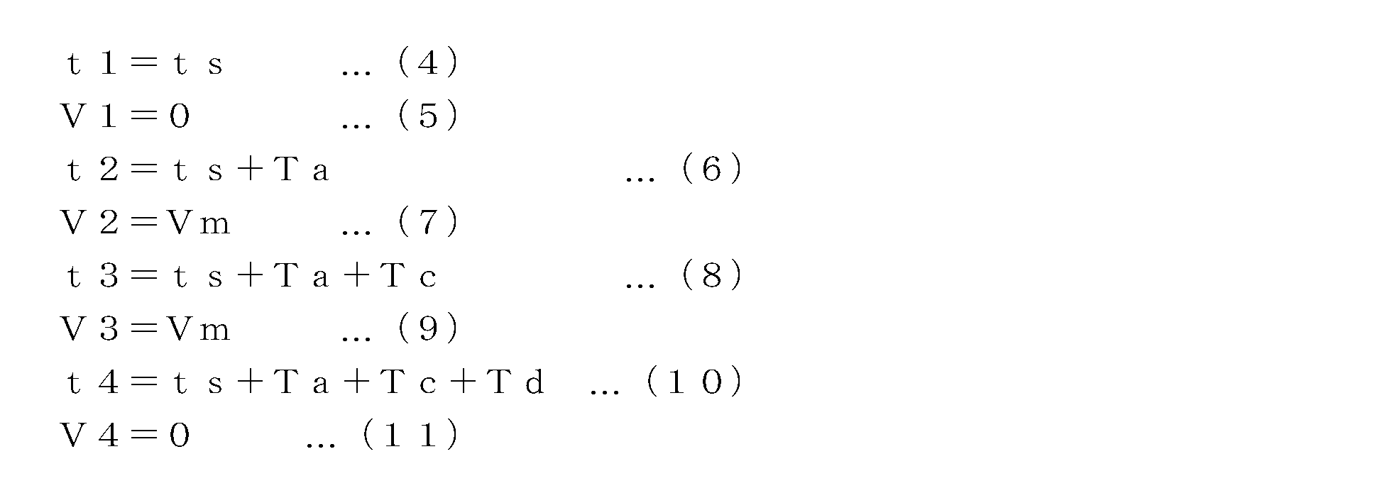

一方、S102において、移動量Xが移動量X1より大きくなければ、第二タイムチャートを算出するべく、チャート算出部12bはまず、移動量Xが移動量X1に等しいか否かを判断する(S105)。そして、等しければ、定常運転時間Tcが零である三角形状の波形、すなわち図10(b)に示す波形の各頂点P1~P3の座標(tr1,Vr1)~(tr3,Vr3)を指定された加速時間及び減速時間を用いる場合には次式(20)~(25)に従って、指定された加速度及び減速度を用いる場合には次式(26)~(31)に従って、算出する(S106)。


また、S105において移動量Xが移動量X1に等しくなければ、最大速度Vmを補正する(S107)。具体的には、指定された加速時間Ta及び減速時間Td、または指定された加速度Aa及び減速度Adによる三角形状の波形に従ってスライダを移動させた場合に、その移動量が指定された移動量Xとなるよう、最大速度Vmを補正する。補正後の最大速度Vm’は、指定された加速時間及び減速時間を用いる場合には次式(32)により、指定された加速度及び減速度を用いる場合には次式(33)により求められる。


その後、補正後の最大速度Vm’を最大速度Vmの代わりに用いて、三角波形の各頂点を求める(S108)。このときの処理は、S106における処理と同一で良い。すなわち、波形の各頂点P1~P3の座標(tr1,Vr1)~(tr3,Vr3)を指定された加速時間及び減速時間を用いる場合には前述の式(20)~(25)に従って、指定された加速度及び減速度を用いる場合には前述の式(26)~(31)に従って、算出する。
図11(a)は、補正後の最大速度Vm’を最大速度Vmの代わりとし、指定された加速時間及び減速時間を用いて求められた三角波形を示す図であり、図11(b)は、同じく補正後の最大速度Vm’を最大速度Vmの代わりとし、指定された加速度及び減速度を用いて求められた三角波形を示す図である。なお、図11(a)及び図11(b)では、Vm=Vm’である場合の三角波形を参考のため一点鎖線で示した。図11(a)に示されるように、指定された加速時間及び減速時間を用いる場合には、得られる第二タイムチャートは指定された加速時間Ta及び減速時間Tdがスライダの動作に反映されたものとなる。一方、図11(b)に示されるように、指定された加速度及び減速度を用いる場合には、得られる第二タイムチャートは、指定された加速度Aa及び減速度Adがスライダの動作に反映されたものとなる。すなわち三角波形の加速時及び減速時の傾きは指定された通りの値であり変化しない。
なお、最大速度Vmを補正する場合には、画面に補正後の最大速度Vm’を表示するとともに、例えば「最大速度Vmを変更する必要があります。」などのメッセージを出力するとともに、ウィンドウ34の最大速度に係る数値入力欄に補正後の最大速度Vm’を設定して表示し、ユーザの確認を求めるようにしてもよい。この状態で、ユーザがOKボタン34aを再度クリックすれば、補正後の最大速度Vm’を用いて、図9のS108の処理が実行されることになる。なお、S107において算出される補正後の最大速度Vm’が微小値の場合にはエラーメッセージを出力するようにしてよい。
以上説明したように、本実施形態に係るタイムチャート作成装置10は、指定された加速時間及び減速時間を用いてタイムチャートを作成する場合と、指定された加速度及び減速度を用いてタイムチャートを作成する場合を含んでいる。さらに、図6にて説明したように、指定された加速時間及び減速時間を用いる場合と指定された加速度及び減速度を用いる場合とを選択することもできる。
この点について説明すると、発明者の知見によれば、背景技術として提示したものを含め、従来知られているタイムチャート作成装置では、デフォルトでどのような速度波形が形成されるのかは一義で決定されている。これに対し機械要素制御システムを構築するに際しては、例えば、機械要素の制約上などの理由により、加速度等を一定にして機械要素を動かすことが望まれる場合や、それと反して、加速時間等を一定にして機械要素を動かすことが望まれる場合などが存在する。
しかしながら、従来知られているタイムチャート作成装置では、タイムチャートは簡易的に作成され、また、作成されたタイムチャートはラダー言語等の他の言語に変換されてしまい、機械要素の詳細な速度波形を記述することが難しいといった背景から、タイムチャートを作成する上でこのような要請は無視されており、タイムチャート作成装置が現実的に普及しない理由の一つとなっている。しかしながら、本実施形態に係るタイムチャート作成装置10によれば、加速度或いは加速時間等の、機械要素の詳細な速度波形を反映したタイムチャートを作成することができる。これにより、加速度等を一定にして機械要素を動かすことが望まれるような場合にも、そのような要請に応じた適切なタイムチャートを作成することができる。また、加速時間等を一定にして機械要素を動かすことが望まれる場合にも、そのような要請に応じた適切なタイムチャートを作成することができる。更に、これら相異なる性質のタイムチャートのいずれを作成するのかを選択することで、ユーザの細やかな要請に対応することが可能である。従って、本実施形態に係るタイムチャート作成装置10によれば、よりタイムチャートによる機械要素の動作の記述の柔軟性を高め、ユーザの利便性を向上させることが可能である。
ところで、図5に示したタイムチャートでは、ユニット毎の動作と、その相互の関係が視覚的に理解しやすい形で示されている一方、その動作が事前に定まっていない信号に応答する出力ユニットの動作を十分に記述できない。図5の例では、ユニット4であるLED110の動作はユニット2であるサーボユニット105のタイムチャート20-2と、サーボユニット105の動作に応じて作動するセンサ104のタイムチャート20-3に関連付けられており、サーボユニット105の動作を定めると、LED110の動作も概ね予測可能である。これに対し、ユニット1であるプッシュスイッチ102は人為的に操作されるものであるから、どのような操作がなされるかを事前に予測することはできず、そのため、例えばプッシュスイッチ102の操作に連動してLED110が点灯するといった動作をタイムチャートとして記述することは難しい。
そこで、本実施形態のタイムチャート作成装置10では、特定の出力ユニット(ここではLED110)への出力を、任意の入力ユニットからの入力信号及び任意の出力ユニットへの出力信号の少なくとも一方に連動して変化するようにする設定(出力連動設定)が可能となっている。
具体的には、図12に示すように、入力受付部12aは、出力ユニットであるLED110を選択することにより例えばGUIとしてウィンドゥ35を表示し、チェックボックス35aをチェックすることにより出力連動設定をすることが可能である。チェックボックス35aをチェックし、入力欄35bに出力を連動させる対象(出力連動元)となる入力ユニット及び出力ユニットのいずれかを選択することにより、当該出力ユニットの出力は選択された入力ユニット又は出力ユニットの信号に連動して変化するようになる。図12の例では、入力欄35bにユニット1であるプッシュスイッチ102が選択されているため、プッシュスイッチ102の押下げ及びその解除に連動してLED102が点灯及び消灯することになる。なお、このときタイムチャート上では出力連動設定がされたユニットの波形は表示されず、出力連動設定がなされている旨及びその出力連動元が表示されるようになっている。
この点について説明すると、そもそもタイムチャートは機器の動作を時間軸上に記述するものであり、ラダー言語のような論理回路を記述することを主とするものとは異なっている。そのため、発明者の知見によれば、背景技術として提示したものを含め、従来知られているタイムチャート作成装置では、タイムチャートを用いて機器の動作を記述するにあたり、例えば任意のタイミングに入力信号を受け付け、その信号と連動して出力信号を出力するような論理演算で記述されるような処理は考慮されていない。これに対し、本実施形態に係るタイムチャート作成装置10によれば、出力連動設定手段を有することにより、時間軸上に機器の動作を記述するタイムチャートでありながら、このような簡易の論理演算処理を可能としている。従って、タイムチャート作成の自由度を大幅に向上させることができる。
なお、ウィンドゥ35中のチェックボックス35cをチェックすると、出力連動設定がされた出力ユニットの出力が、出力連動元である入力ユニット又は出力ユニットの信号に対して反転したものとなる。このウィンドゥ35は入力受付部12aにより実現される出力連動設定手段の一例である。
以上説明した本実施形態によれば、スライダその他の機械要素の移動量等の情報を入力することで、当該機械要素の速度遷移を示すタイムチャートが自動生成される。そして、このタイムチャートは、コントローラ100において解釈・実行可能な制御データに変換される。このため、ユーザは機械要素の移動量という直感的な情報を入力するだけで、機械要素に対し、移動速度が徐々に増加し、その後に徐々に減少する動作を行わせることができるようになる。
なお、以上の説明では、説明の簡単のために直線移動する機械要素であるスライダを取り上げたが、回転移動する機械要素であっても本発明は同様に適用できる。
Claims (14)
- 機械要素の移動量の入力を受け付ける移動量受付手段と、
前記移動量に基づいて、前記機械要素の移動速度が増加し、又は減少する速度遷移を含むタイムチャートを算出するタイムチャート算出手段と、
前記タイムチャートに基づいて、前記機械要素を制御するための制御データを出力する制御データ出力手段と、
を含むタイムチャート作成装置において、
前記機械要素の加速時間又は減速時間の少なくとも一方の入力を受け付ける加減速時間受付手段、及び前記機械要素の加速度又は減速度の少なくとも一方の入力を受け付ける加減速度受付手段の少なくとも一方をさらに含み、
前記タイムチャート算出手段は、前記移動量と、前記加速時間、前記減速時間、前記加速度及び前記減速度の少なくともいずれかとに基づいて前記タイムチャートを算出する、
タイムチャート作成装置。 - 請求項1に記載のタイムチャート作成装置において、
前記タイムチャート算出手段は、前記移動量に応じて、少なくとも加速、定速及び減速動作を前記機械要素にさせる第一タイムチャートと、加速後減速に転じる動作を前記機械要素にさせる第二タイムチャートとを選択的に算出する
タイムチャート作成装置。 - 請求項2に記載のタイムチャート作成装置において、
前記タイムチャート算出手段は、前記第二タイムチャートを算出する際に、前記加速時間又は前記減速時間の少なくとも一方が前記機械要素の動作として反映されるタイムチャートを算出する、
タイムチャート作成装置。 - 請求項2又は3に記載のタイムチャート作成装置において、
前記タイムチャート算出手段は、前記第二タイムチャートを算出する際に、前記加速度又は前記減速度の少なくとも一方が前記機械要素の動作として反映されるタイムチャートを算出する、
タイムチャート作成装置。 - 請求項2に記載のタイムチャート作成装置において、
前記タイムチャート算出手段は、前記第二タイムチャートを算出する際に、前記加速時間又は前記減速時間の少なくとも一方が前記機械要素の動作として反映されるタイムチャートと、前記加速度又は前記減速度の少なくとも一方が前記機械要素の動作として反映されるタイムチャートと、を選択可能である、
タイムチャート作成装置。 - 請求項1に記載のタイムチャート作成装置において、
入力ユニットからの入力に変化が生じるタイミングを受け付ける入力変化タイミング受付手段と、
前記入力ユニットからの入力に変化が生じるタイミングと、前記タイムチャートが示す前記機械要素が移動を開始するタイミングと、の関連付けの入力を受け付ける関連付け受付手段と、をさらに含み、
前記制御データ出力手段は、前記関連付けの入力が受け付けられる場合に、前記入力ユニットからの入力に変化が生じることを条件として、前記機械要素に移動を開始させるための制御データを出力する、
タイムチャート作成装置。 - 請求項1乃至6のいずれかに記載のタイムチャート作成装置において、
特定の出力ユニットへの出力を、任意の入力ユニットからの入力信号及び任意の出力ユニットへの出力信号の少なくとも一方に連動して変化するよう設定する、出力連動設定手段を有する、
タイムチャート作成装置。 - 請求項7に記載のタイムチャート作成装置において、
前記出力連動設定手段は、前記特定の出力ユニットへの出力を、前記入力信号及び前記出力信号の少なくとも一方に対し反転させるか否かを設定する、
タイムチャート作成装置。 - 請求項2乃至5のいずれかに記載のタイムチャート作成装置において、
前記機械要素の最大速度の入力を受け付ける最大速度受付手段をさらに含み、
前記タイムチャート算出手段は、前記第一タイムチャートを算出する際に、前記定速動作における前記機械要素の速度を前記最大速度とする、
タイムチャート作成装置。 - 請求項1乃至8のいずれかに記載のタイムチャート作成装置において作成されたタイムチャートを実行して前記機械要素を制御するコントローラ。
- 請求項10に記載のコントローラと、
前記コントローラにより制御可能となるよう接続された機械要素と、
を少なくとも備えた機械要素制御システム。 - 機械要素の移動量の入力を受け付けるステップと、
前記移動量に基づいて、前記機械要素の移動速度が増加し、又は減少する速度遷移を含むタイムチャートを算出するステップと、
前記タイムチャートに基づいて、前記機械要素を制御するための制御データを出力するステップと、
を含むタイムチャート作成方法において、
前記機械要素の加速時間又は減速時間の少なくとも一方の入力を受け付けるステップ、及び前記機械要素の加速度又は減速度の少なくとも一方の入力を受け付けるステップの少なくとも一方をさらに含み、
前記タイムチャートを算出するステップは、前記移動量と、前記加速時間、前記減速時間、前記加速度及び前記減速度の少なくともいずれかとに基づいて前記タイムチャートを算出する、
タイムチャート作成方法。 - 機械要素の移動量の入力を受け付ける移動量受付手段、
前記移動量に基づいて、前記機械要素の移動速度が増加し、又は減少する速度遷移を含むタイムチャートを算出するタイムチャート算出手段、
前記タイムチャートに基づいて、前記機械要素を制御するための制御データを出力する制御データ出力手段、
としてコンピュータを機能させるためのプログラムであって、
さらに前記機械要素の加速時間又は減速時間の少なくとも一方の入力を受け付ける加減速時間受付手段、及び前記機械要素の加速度又は減速度の少なくとも一方の入力を受け付ける加減速度受付手段の少なくとも一方として前記コンピュータを機能させ、
前記タイムチャート算出手段は、前記移動量と、前記加速時間、前記減速時間、前記加速度及び前記減速度の少なくともいずれかとに基づいて前記タイムチャートを算出する、
プログラム。 - 機械要素の移動量の入力を受け付ける移動量受付手段、
前記移動量に基づいて、前記機械要素の移動速度が増加し、又は減少する速度遷移を含むタイムチャートを算出するタイムチャート算出手段、
前記タイムチャートに基づいて、前記機械要素を制御するための制御データを出力する制御データ出力手段、
としてコンピュータを機能させるためのプログラムを記憶したコンピュータ可読情報記憶媒体であって、
さらに前記機械要素の加速時間又は減速時間の少なくとも一方の入力を受け付ける加減速時間受付手段、及び前記機械要素の加速度又は減速度の少なくとも一方の入力を受け付ける加減速度受付手段の少なくとも一方として前記コンピュータを機能させ、
前記タイムチャート算出手段は、前記移動量と、前記加速時間、前記減速時間、前記加速度及び前記減速度の少なくともいずれかとに基づいて前記タイムチャートを算出する、
プログラムを記憶したコンピュータ可読情報記憶媒体。
Priority Applications (3)
| Application Number | Priority Date | Filing Date | Title |
|---|---|---|---|
| JP2014512454A JP5994848B2 (ja) | 2012-04-27 | 2013-04-09 | タイムチャート作成装置、コントローラ、機械要素制御システム、タイムチャート作成方法、プログラム及び情報記憶媒体 |
| CN201380022403.XA CN104272201A (zh) | 2012-04-27 | 2013-04-09 | 时间图制作装置、控制器、机械元件控制系统、时间图制作方法、程序以及信息存储介质 |
| US14/524,354 US20150045958A1 (en) | 2012-04-27 | 2014-10-27 | Time chart creation apparatus, controller, machine element control system, time chart creation method, and information storage medium |
Applications Claiming Priority (2)
| Application Number | Priority Date | Filing Date | Title |
|---|---|---|---|
| JPPCT/JP2012/061492 | 2012-04-27 | ||
| JP2012061492 | 2012-04-27 |
Related Child Applications (1)
| Application Number | Title | Priority Date | Filing Date |
|---|---|---|---|
| US14/524,354 Continuation US20150045958A1 (en) | 2012-04-27 | 2014-10-27 | Time chart creation apparatus, controller, machine element control system, time chart creation method, and information storage medium |
Publications (1)
| Publication Number | Publication Date |
|---|---|
| WO2013161561A1 true WO2013161561A1 (ja) | 2013-10-31 |
Family
ID=49482890
Family Applications (1)
| Application Number | Title | Priority Date | Filing Date |
|---|---|---|---|
| PCT/JP2013/060758 Ceased WO2013161561A1 (ja) | 2012-04-27 | 2013-04-09 | タイムチャート作成装置、コントローラ、機械要素制御システム、タイムチャート作成方法、プログラム及び情報記憶媒体 |
Country Status (4)
| Country | Link |
|---|---|
| US (1) | US20150045958A1 (ja) |
| JP (1) | JP5994848B2 (ja) |
| CN (1) | CN104272201A (ja) |
| WO (1) | WO2013161561A1 (ja) |
Cited By (3)
| Publication number | Priority date | Publication date | Assignee | Title |
|---|---|---|---|---|
| JP2020091597A (ja) * | 2018-12-04 | 2020-06-11 | キヤノン株式会社 | プログラム作成装置、および物品の製造方法 |
| JP2021149853A (ja) * | 2020-03-23 | 2021-09-27 | キヤノン株式会社 | 情報処理方法、情報処理装置、生産システム、および物品の製造方法 |
| JP7599616B1 (ja) * | 2023-08-31 | 2024-12-13 | 三菱電機株式会社 | タイムチャート生成プログラム、タイムチャート生成装置、支援システム及びタイムチャート生成方法 |
Families Citing this family (3)
| Publication number | Priority date | Publication date | Assignee | Title |
|---|---|---|---|---|
| JP6747104B2 (ja) * | 2016-06-30 | 2020-08-26 | オムロン株式会社 | セーフティシステム、プログラム、および方法 |
| CN107808421B (zh) * | 2017-10-25 | 2021-01-29 | 国网山东省电力公司莒县供电公司 | 电力抢修工单超时处理系统及处理方法 |
| JP6761158B1 (ja) * | 2019-12-16 | 2020-09-23 | 株式会社安川電機 | プログラム作成装置、プログラム作成方法、及びプログラム |
Citations (4)
| Publication number | Priority date | Publication date | Assignee | Title |
|---|---|---|---|---|
| JPH07191717A (ja) * | 1992-02-05 | 1995-07-28 | Toshiba Corp | 制御プログラム自動作成装置 |
| JP2000259216A (ja) * | 1999-03-12 | 2000-09-22 | Digital Electronics Corp | 産業用制御装置のプログラミングのためのシステムおよび方法ならびにそのソフトウェアが記録された記録媒体 |
| JP2003084838A (ja) * | 2001-09-06 | 2003-03-19 | Sony Corp | 位置決め装置及び位置決め方法 |
| JP2008097281A (ja) * | 2006-10-11 | 2008-04-24 | Canon Inc | プログラム生成システム、シーケンスプログラム、シーケンス制御方法、およびシーケンサ装置 |
Family Cites Families (3)
| Publication number | Priority date | Publication date | Assignee | Title |
|---|---|---|---|---|
| JP2003228403A (ja) * | 2002-02-01 | 2003-08-15 | Ide Keiki:Kk | シーケンス制御方法及びシーケンサー装置 |
| US8687693B2 (en) * | 2007-11-30 | 2014-04-01 | Dolby Laboratories Licensing Corporation | Temporal image prediction |
| JP5532306B2 (ja) * | 2010-01-13 | 2014-06-25 | Dmg森精機株式会社 | 工作機械 |
-
2013
- 2013-04-09 JP JP2014512454A patent/JP5994848B2/ja active Active
- 2013-04-09 WO PCT/JP2013/060758 patent/WO2013161561A1/ja not_active Ceased
- 2013-04-09 CN CN201380022403.XA patent/CN104272201A/zh active Pending
-
2014
- 2014-10-27 US US14/524,354 patent/US20150045958A1/en not_active Abandoned
Patent Citations (4)
| Publication number | Priority date | Publication date | Assignee | Title |
|---|---|---|---|---|
| JPH07191717A (ja) * | 1992-02-05 | 1995-07-28 | Toshiba Corp | 制御プログラム自動作成装置 |
| JP2000259216A (ja) * | 1999-03-12 | 2000-09-22 | Digital Electronics Corp | 産業用制御装置のプログラミングのためのシステムおよび方法ならびにそのソフトウェアが記録された記録媒体 |
| JP2003084838A (ja) * | 2001-09-06 | 2003-03-19 | Sony Corp | 位置決め装置及び位置決め方法 |
| JP2008097281A (ja) * | 2006-10-11 | 2008-04-24 | Canon Inc | プログラム生成システム、シーケンスプログラム、シーケンス制御方法、およびシーケンサ装置 |
Cited By (5)
| Publication number | Priority date | Publication date | Assignee | Title |
|---|---|---|---|---|
| JP2020091597A (ja) * | 2018-12-04 | 2020-06-11 | キヤノン株式会社 | プログラム作成装置、および物品の製造方法 |
| JP2021149853A (ja) * | 2020-03-23 | 2021-09-27 | キヤノン株式会社 | 情報処理方法、情報処理装置、生産システム、および物品の製造方法 |
| US12001186B2 (en) | 2020-03-23 | 2024-06-04 | Canon Kabushiki Kaisha | Information processing method, information processing apparatus, production system and article manufacturing method |
| JP7599616B1 (ja) * | 2023-08-31 | 2024-12-13 | 三菱電機株式会社 | タイムチャート生成プログラム、タイムチャート生成装置、支援システム及びタイムチャート生成方法 |
| WO2025046890A1 (ja) * | 2023-08-31 | 2025-03-06 | 三菱電機株式会社 | タイムチャート生成プログラム、タイムチャート生成装置、支援システム及びタイムチャート生成方法 |
Also Published As
| Publication number | Publication date |
|---|---|
| JP5994848B2 (ja) | 2016-09-21 |
| US20150045958A1 (en) | 2015-02-12 |
| JPWO2013161561A1 (ja) | 2015-12-24 |
| CN104272201A (zh) | 2015-01-07 |
Similar Documents
| Publication | Publication Date | Title |
|---|---|---|
| JP5994848B2 (ja) | タイムチャート作成装置、コントローラ、機械要素制御システム、タイムチャート作成方法、プログラム及び情報記憶媒体 | |
| JP6915543B2 (ja) | ロボット教示装置、コンピュータプログラム及びロボット教示方法 | |
| TWI553540B (zh) | 突顯顯示器上之物件 | |
| US11007646B2 (en) | Programming assistance apparatus, robot system, and method for generating program | |
| CN106457571A (zh) | 离线示教装置 | |
| JP2016059980A (ja) | ロボットの動作監視領域を設定するロボットシステム | |
| US10201903B1 (en) | Punch-in / punch-out smoothing for takeover of automated movement with haptic controller | |
| JP6464204B2 (ja) | オフラインプログラミング装置及び位置パラメータ補正方法 | |
| JP5875555B2 (ja) | 画像作成システム | |
| CN107450480A (zh) | 运动部件的控制装置、控制方法、介质和系统 | |
| CN107562017A (zh) | 运动控制部件的参数编辑方法、计算机可读介质和计算机 | |
| JP5931638B2 (ja) | 数値制御システムおよび数値制御データ生成方法 | |
| JP6215003B2 (ja) | プログラマブルコントローラ、拡張ユニット及びプログラム作成支援システム | |
| TW201606468A (zh) | 定位控制裝置之同步控制設定方法及定位控制裝置之控制設定裝置 | |
| WO2014126109A1 (ja) | コントローラ、タイムチャート作成装置、コンピュータプログラム及びコンピュータ可読情報記憶媒体 | |
| JP2010176241A (ja) | プログラマブル表示器、機器監視システム、及び制御プログラム | |
| JP2011175351A (ja) | 画面データ作成装置、画面データ作成方法、及び画面データ作成プログラム | |
| US20140236317A1 (en) | Controller, time chart creation device, information storage medium, device control method, and time chart creation method | |
| JP6591116B1 (ja) | プログラマブルロジックコントローラのcpuユニット、プログラマブルロジックコントローラ、方法、及びコンピュータ | |
| WO2017195362A1 (ja) | テスト装置 | |
| JP6712500B2 (ja) | デバイスモニタ装置、デバイスモニタ方法、デバイスモニタシステム、及びデバイスモニタ装置で実行することが可能なコンピュータプログラム | |
| US10025884B1 (en) | Manipulation tool for offset surface of a simulation model | |
| JP6136505B2 (ja) | タイムチャート作成装置、コントローラ、機器制御システム、コンピュータプログラム及びコンピュータ可読情報記憶媒体 | |
| JP2016045719A (ja) | エンジニアリング装置および画面表示制御方法 | |
| JP7600743B2 (ja) | 制御システム、制御方法および制御装置 |
Legal Events
| Date | Code | Title | Description |
|---|---|---|---|
| 121 | Ep: the epo has been informed by wipo that ep was designated in this application |
Ref document number: 13781018 Country of ref document: EP Kind code of ref document: A1 |
|
| ENP | Entry into the national phase |
Ref document number: 2014512454 Country of ref document: JP Kind code of ref document: A |
|
| NENP | Non-entry into the national phase |
Ref country code: DE |
|
| 122 | Ep: pct application non-entry in european phase |
Ref document number: 13781018 Country of ref document: EP Kind code of ref document: A1 |