WO2013161024A1 - 蛇行判定装置 - Google Patents
蛇行判定装置 Download PDFInfo
- Publication number
- WO2013161024A1 WO2013161024A1 PCT/JP2012/061114 JP2012061114W WO2013161024A1 WO 2013161024 A1 WO2013161024 A1 WO 2013161024A1 JP 2012061114 W JP2012061114 W JP 2012061114W WO 2013161024 A1 WO2013161024 A1 WO 2013161024A1
- Authority
- WO
- WIPO (PCT)
- Prior art keywords
- vehicle
- vehicle speed
- detection unit
- meandering
- unit
- Prior art date
- Legal status (The legal status is an assumption and is not a legal conclusion. Google has not performed a legal analysis and makes no representation as to the accuracy of the status listed.)
- Ceased
Links
Images

Classifications
-
- G—PHYSICS
- G06—COMPUTING OR CALCULATING; COUNTING
- G06V—IMAGE OR VIDEO RECOGNITION OR UNDERSTANDING
- G06V20/00—Scenes; Scene-specific elements
- G06V20/50—Context or environment of the image
- G06V20/56—Context or environment of the image exterior to a vehicle by using sensors mounted on the vehicle
- G06V20/588—Recognition of the road, e.g. of lane markings; Recognition of the vehicle driving pattern in relation to the road
-
- G—PHYSICS
- G08—SIGNALLING
- G08G—TRAFFIC CONTROL SYSTEMS
- G08G1/00—Traffic control systems for road vehicles
- G08G1/16—Anti-collision systems
- G08G1/167—Driving aids for lane monitoring, lane changing, e.g. blind spot detection
-
- B—PERFORMING OPERATIONS; TRANSPORTING
- B60—VEHICLES IN GENERAL
- B60W—CONJOINT CONTROL OF VEHICLE SUB-UNITS OF DIFFERENT TYPE OR DIFFERENT FUNCTION; CONTROL SYSTEMS SPECIALLY ADAPTED FOR HYBRID VEHICLES; ROAD VEHICLE DRIVE CONTROL SYSTEMS FOR PURPOSES NOT RELATED TO THE CONTROL OF A PARTICULAR SUB-UNIT
- B60W30/00—Purposes of road vehicle drive control systems not related to the control of a particular sub-unit, e.g. of systems using conjoint control of vehicle sub-units
- B60W30/10—Path keeping
- B60W30/12—Lane keeping
-
- G—PHYSICS
- G08—SIGNALLING
- G08B—SIGNALLING SYSTEMS, e.g. PERSONAL CALLING SYSTEMS; ORDER TELEGRAPHS; ALARM SYSTEMS
- G08B21/00—Alarms responsive to a single specified undesired or abnormal condition and not otherwise provided for
- G08B21/02—Alarms for ensuring the safety of persons
- G08B21/06—Alarms for ensuring the safety of persons indicating a condition of sleep, e.g. anti-dozing alarms
-
- B—PERFORMING OPERATIONS; TRANSPORTING
- B60—VEHICLES IN GENERAL
- B60W—CONJOINT CONTROL OF VEHICLE SUB-UNITS OF DIFFERENT TYPE OR DIFFERENT FUNCTION; CONTROL SYSTEMS SPECIALLY ADAPTED FOR HYBRID VEHICLES; ROAD VEHICLE DRIVE CONTROL SYSTEMS FOR PURPOSES NOT RELATED TO THE CONTROL OF A PARTICULAR SUB-UNIT
- B60W2420/00—Indexing codes relating to the type of sensors based on the principle of their operation
- B60W2420/40—Photo, light or radio wave sensitive means, e.g. infrared sensors
- B60W2420/403—Image sensing, e.g. optical camera
-
- B—PERFORMING OPERATIONS; TRANSPORTING
- B60—VEHICLES IN GENERAL
- B60W—CONJOINT CONTROL OF VEHICLE SUB-UNITS OF DIFFERENT TYPE OR DIFFERENT FUNCTION; CONTROL SYSTEMS SPECIALLY ADAPTED FOR HYBRID VEHICLES; ROAD VEHICLE DRIVE CONTROL SYSTEMS FOR PURPOSES NOT RELATED TO THE CONTROL OF A PARTICULAR SUB-UNIT
- B60W2520/00—Input parameters relating to overall vehicle dynamics
- B60W2520/10—Longitudinal speed
-
- B—PERFORMING OPERATIONS; TRANSPORTING
- B60—VEHICLES IN GENERAL
- B60W—CONJOINT CONTROL OF VEHICLE SUB-UNITS OF DIFFERENT TYPE OR DIFFERENT FUNCTION; CONTROL SYSTEMS SPECIALLY ADAPTED FOR HYBRID VEHICLES; ROAD VEHICLE DRIVE CONTROL SYSTEMS FOR PURPOSES NOT RELATED TO THE CONTROL OF A PARTICULAR SUB-UNIT
- B60W2520/00—Input parameters relating to overall vehicle dynamics
- B60W2520/20—Sideslip angle
-
- B—PERFORMING OPERATIONS; TRANSPORTING
- B60—VEHICLES IN GENERAL
- B60W—CONJOINT CONTROL OF VEHICLE SUB-UNITS OF DIFFERENT TYPE OR DIFFERENT FUNCTION; CONTROL SYSTEMS SPECIALLY ADAPTED FOR HYBRID VEHICLES; ROAD VEHICLE DRIVE CONTROL SYSTEMS FOR PURPOSES NOT RELATED TO THE CONTROL OF A PARTICULAR SUB-UNIT
- B60W2540/00—Input parameters relating to occupants
- B60W2540/18—Steering angle
Definitions
- the present invention relates to a meandering determination apparatus including a turning information detection unit that detects turning information of a vehicle, and an image recognition detection unit that detects position information of the vehicle with respect to a lane by image recognition on a captured image including a running road.
- Patent Document 1 discloses an image recognition detection unit that detects a relative position of a vehicle with respect to a lane by recognizing a lane based on a vehicle front image captured by a vehicle-mounted camera, and a steering angle detection unit that detects a steering angle of a steering wheel. It is disclosed that the meandering is determined using two detection means in combination.
- lanes are maintained on highways such as highways and bypasses, and lanes can be recognized by image recognition detection means.
- the higher the speed the smaller the rudder angle for turning the vehicle and meandering with a small rudder angle, so it is difficult to determine the meander with high accuracy using the rudder angle detected by the rudder angle detection means. become.
- the lower the speed the larger the steering angle for turning the vehicle and meandering with a large steering angle. Therefore, it is possible to determine the meandering with high accuracy using the steering angle detected by the steering angle detection means. It is.
- the meandering determination may be performed based on information with low reliability depending on the vehicle speed range, and the meandering determination is performed with high accuracy. There is room for improvement. Moreover, since two detection means are always operating, there is a problem that energy efficiency is also poor.
- an object of the present invention is to provide a meandering determination device that can determine meandering with high efficiency and energy efficiency with a configuration including two detection means for determining meandering.
- a meandering determination device includes a turning information detection unit that detects turning information of a vehicle, and an image recognition detection unit that detects position information of the vehicle with respect to a lane by image recognition on a captured image including a running road.
- a meandering determination device that detects a vehicle speed and selects an image recognition detection unit when the vehicle speed detected by the vehicle speed detection unit is equal to or higher than a predetermined vehicle speed, and the vehicle speed detected by the vehicle speed detection unit is less than the predetermined vehicle speed.
- a selection unit that selects a turning information detection unit, and when an image recognition detection unit is selected by the selection unit, the meandering of the vehicle is determined based on the position information of the vehicle with respect to the lane, and the turning information detection unit is selected by the selection unit
- a meandering determination unit that determines the meandering of the vehicle based on the turning information of the vehicle.
- the meandering determination device includes two detection means, a turning information detection unit and an image recognition detection unit, and determines the meandering of the vehicle using one of the two detection means.
- the turning information detection unit is means for detecting turning information (for example, steering angle, steering angle speed, yaw rate) of the vehicle. The higher the speed, the smaller the steering angle for turning the vehicle, and it becomes difficult to determine meandering with high accuracy using the turning information detected by the turning information detection unit. On the other hand, the lower the speed, the larger the steering angle for turning the vehicle, etc., so that meandering can be determined using the turning information detected by the turning information detection unit.
- the image recognition detection unit is a means for recognizing a running lane by image recognition on a captured image including a running road and detecting position information of the vehicle with respect to the lane (for example, an offset amount (lateral position) with respect to the center of the lane). is there.
- the lanes are generally maintained on roads that can travel at relatively high speeds such as highways, bypasses, and freeways. In such an environment where the lane is maintained, the lane can be recognized by the image recognition detection unit, and the position information of the vehicle with respect to the lane can be obtained.
- roads that are expected to travel at low speed, such as residential areas often have intermittent lanes or no lanes due to the presence of intersections, facing roads, narrow roads, and the like. In such an environment where the lanes are not maintained, it is difficult for the image recognition detection unit to recognize the lanes (the lanes may not be recognized at all), and the vehicle position information with respect to the lanes cannot be obtained.
- the vehicle speed detection unit detects the vehicle speed
- the selection unit selects the image recognition detection unit as detection means for determining the meandering when the vehicle speed is equal to or higher than the predetermined vehicle speed, and the vehicle speed is less than the predetermined vehicle speed.
- the turning information detection unit is selected.
- the predetermined vehicle speed is determined by the vehicle using the image recognition detection unit, the vehicle speed range (high speed side) in which highly reliable information for determining the meandering and the turning information detecting unit is used. This is the vehicle speed at the boundary with the vehicle speed range (low speed side) from which highly reliable information can be obtained.
- the meander determination device when the image recognition detection unit is selected by the meander determination unit, the meander of the vehicle is determined based on the position information of the vehicle with respect to the lane, and the turning information detection unit is selected. The vehicle meander is determined based on the turning information of the vehicle.
- the meandering determination device uses only detection means effective (highly reliable) for meandering determination according to the vehicle speed, so that energy efficiency is improved, and meandering is determined with high accuracy in all vehicle speed ranges. be able to. Note that stopping the detection means not used for meander determination provides the best energy efficiency. However, even when the detection means cannot be stopped, the meander determination process is performed using only the information of one detection means (that is, both detections are detected). Since the meandering determination process is not performed using each information of the means), the processing load is reduced and the energy efficiency is improved.
- a learning unit that determines a predetermined vehicle speed based on the vehicle speed detected by the vehicle speed detection unit when a state where the lane can be recognized by the image recognition detection unit and a state where the lane cannot be recognized are switched. It is suitable to provide.
- the image recognition detection unit actually learns the predetermined vehicle speed based on the vehicle speed when the state where the lane can be recognized by the image recognition detection unit and the state where the lane cannot be recognized are switched.
- the meandering determination can be performed using the image recognition detection unit in a vehicle speed range where the lane can be recognized.
- the energy efficiency is improved, and the meandering can be judged with high accuracy in all the vehicle speed ranges.
- the present invention is applied to a consciousness deterrence determination system that determines whether or not a driver is in a state of reduced consciousness and issues an alarm when the driver is in a state of reduced consciousness.
- the consciousness deterioration determination system includes two detection means, a white line recognition camera and a rudder angle sensor, and determines whether or not there is meandering (flickering) using either one of the sensing means. The driver determines that the driver is in a state of reduced consciousness.
- the operation of the consciousness deterioration determination system may operate when the ACC power source is turned on or the engine is started, or predetermined operating conditions or cancellation conditions may be provided.
- an operation condition for example, the system operation is performed when the vehicle speed is equal to or higher than a predetermined speed.
- Cancellation conditions include, for example, temporarily stopping the system when the blinker switch is turned on in the left direction or on the right direction so as not to operate during lane change, or temporarily depending on the operation of other drivers besides the blinker. Alternatively, the system may be stopped.
- FIG. 1 is a configuration diagram of a consciousness deterioration determination system.
- the low consciousness determination system 1 uses only a white line recognition camera in the high speed range in order to determine the meandering with high energy efficiency and high accuracy in all vehicle speed ranges, and the offset amount from the center of the lane (position information of the vehicle with respect to the lane)
- the meandering determination is performed based on the steering angle, and only the steering angle sensor is used in the low speed range, and the meandering determination is performed based on the steering angle (turning information).
- the consciousness deterioration determination system 1 uses the vehicle speed at the time of transition from the white line unrecognized state to the recognized state in the white line recognition camera. Learn range switching vehicle speed.
- corrective steering is performed so that the lateral position of the vehicle greatly deviates from the center of the lane and then returns to the center of the lane, and such corrective steering is repeated. May meander.
- the driver's consciousness reduction state can be determined.
- corrective steering is performed in the opposite direction after the vehicle approaches the left and right white lines, and this corrective steering is repeated periodically.
- the offset amount change pattern indicating the meandering of the vehicle for example, the offset amount (the lateral position of the vehicle) on one side on the left and right sides in the lane gradually increases, and on one side when the correction steering to the other side starts.
- the offset amount on one side gradually decreases to zero
- the offset amount on the other side gradually increases, and when the correction steering to one side starts, the other
- the offset amount on the side becomes a peak
- the offset amount on the other side gradually decreases and becomes 0, and the change in the offset amount on which the offset amount on the one side gradually increases is repeated.
- the change pattern of the steering angle indicating the meandering of the vehicle is, for example, a predetermined amount of steering angle (peak) in one rotation direction of the steering wheel, and one rotation after the start of the correction steering in the other rotation direction.
- the steering angle in one direction rapidly decreases to zero, the steering angle in the other rotation direction increases rapidly, a predetermined amount of steering angle (peak) in the other rotation direction continues, and one rotation direction
- the steering angle in the other rotational direction is rapidly reduced to 0 after the start of the correction steering to, and the steering angle change in which the steering angle in the one rotational direction is rapidly increased is repeated.
- the consciousness lowering determination system 1 includes a white line recognition camera 10, a steering angle sensor 11, a vehicle speed sensor 12, an alarm device 20, an ECU [Electronic Control Unit] 30 (meander determination means selection unit 31, a meandering presence / absence determination unit 32, an alarm control unit 33). , A threshold learning unit 34).
- the white line recognition camera 10 corresponds to the image recognition detection unit described in the claims
- the steering angle sensor 11 corresponds to the turning information detection unit described in the claims
- the meandering determination means selection unit 31 corresponds to the selection unit described in the claims
- the meandering presence / absence determination unit 32 corresponds to the meandering determination unit described in the claims.
- the threshold learning unit 34 corresponds to the learning unit described in the claims.
- the white line recognition camera 10 is a camera sensor that recognizes a pair of left and right white lines constituting a lane, and includes a camera and a processing device.
- the camera is installed in front of the host vehicle and is mounted so that the optical axis direction coincides with the traveling direction of the host vehicle.
- the camera captures a region including a road ahead of the host vehicle at regular time intervals, acquires the captured image, and outputs the image information to the processing device.
- the camera has a wide imaging range in the left-right direction, and can sufficiently capture the white lines on both the left and right sides (a pair) constituting the traveling lane.
- the camera may be a color camera or a monochrome camera.
- the processing device recognizes a pair of left and right white lines constituting the lane in which the vehicle is traveling from the image.
- this recognition method for example, there is a method based on edge processing because a difference in luminance between a road surface and a white line drawn thereon is large.
- the processing device the recognized lane width from the pair of left and right white lines, the line passing through the center of the pair of left and right white lines, the radius and curvature of the curve of the lane center line or each white line, the offset amount from the center of the lane of the own vehicle (Lateral position), yaw angle (direction) with respect to the center line of the vehicle's lane is calculated.
- the white line recognition camera 10 transmits white line recognition results (both side recognition, left side recognition, right side recognition, both side unrecognized, etc.) and various calculated information to the ECU 30 as white line recognition signals at regular time intervals.
- the left and right white lines constituting the lane are generally provided on roads that can be driven at relatively high speeds such as expressways, bypasses, and freeways.
- the white line recognition camera 10 can recognize the white line, and an offset amount with respect to the lane center can be obtained.
- meandering can be determined using the white line recognition camera 10.
- roads such as residential areas that are expected to travel at low speeds
- white lines are often only present intermittently or are not provided due to the presence of intersections, facing roads, narrow roads, and the like.
- the steering angle sensor 11 is a sensor that detects the steering angle of the steering wheel input by the driver.
- the steering angle sensor 11 detects the steering angle at regular intervals, and transmits the detected steering angle to the ECU 30 as a steering angle signal.
- the vehicle speed sensor 12 is a sensor that detects the vehicle speed of the host vehicle.
- the vehicle speed sensor 12 detects the vehicle speed at regular intervals, and transmits the detected vehicle speed to the ECU 30 as a vehicle speed signal.
- the alarm device 20 is a device that outputs an alarm to alert the driver of a state of reduced consciousness.
- an alarm for example, output of an alarm sound from a speaker, display of an alarm screen on a navigation display, lighting of an alarm lamp in a combination meter, generation of seat vibration by a seat vibration generator, steering wheel vibration generator There is a generation of steering vibration.
- the alarm device 20 receives an alarm output signal from the ECU 30, the alarm device 20 outputs an alarm according to the alarm output signal.
- the ECU 30 is an electronic control unit including a CPU [Central Processing Unit], a ROM [Read Only Memory], a RAM [Random Access Memory], and the like.
- an application program stored in the ROM is loaded into the RAM and executed by the CPU, thereby configuring a meandering determination means selection unit 31, a meandering presence / absence determination unit 32, an alarm control unit 33, and a threshold learning unit 34.
- the ECU 30 receives signals from the white line recognition camera 10, the steering angle sensor 11, and the vehicle speed sensor 12, and performs processing in the processing units 31, 32, 33, and 34 using information on each signal.
- the ECU 30 transmits an alarm output signal to the alarm device 20 when it is determined that the state of consciousness is reduced (meandering is present).
- the meander determination means selection unit 31 is a processing unit that selects detection means used for meander determination from the white line recognition camera 10 and the rudder angle sensor 11. Specifically, the meandering determination means selection unit 31 determines whether or not the vehicle speed acquired from the vehicle speed sensor 12 is equal to or higher than the vehicle speed range switching threshold Th_S. As for the vehicle speed range switching threshold Th_S, the direction using the white line recognition camera 10 can obtain highly reliable information for determining the meandering, and the direction using the steering angle sensor 11 causes the meandering. This is a vehicle speed threshold value indicating a boundary with a vehicle speed range (low speed side) from which highly reliable information for determination can be obtained. The initial value of Th_S is set in advance in consideration of the speed limit of the road where the white line is maintained.
- the meandering determination means selection unit 31 selects the white line recognition camera 10 as the detection means used for meandering determination when the vehicle speed is equal to or higher than the vehicle speed range switching threshold Th_S, and meanders when the vehicle speed is less than the vehicle speed range switching threshold Th_S.
- the steering angle sensor 11 is selected as detection means used for determination.
- the meandering presence / absence determination unit 32 is a processing unit that determines whether or not there is meandering using the detection means selected by the meandering determination means selection unit 31 and, when there is meandering, determines that the driver's consciousness is lowered. .
- the meandering presence / absence determination unit 32 when the white line recognition camera 10 is selected by the meander determination unit selection unit 31, time-series data of the offset amount acquired from the white line recognition camera 10 at regular intervals is obtained. It is used to determine whether or not there is meandering from the waveform indicating the change in the offset amount.
- a conventional method is applied as a method for determining the presence or absence of meandering based on the offset amount.
- the third condition is determined for each of the number of times that the peak value that satisfies the condition and the second condition appears continuously is greater than the threshold value. It is determined that there is.
- the meandering presence / absence determination unit 32 when the steering angle sensor 11 is selected by the meandering determination means selection unit 31, the time series data of the steering angle acquired from the steering angle sensor 11 at regular intervals is used.
- the first condition, the second condition, and the third condition are determined using the peak value in the left rotation direction and the peak value in the right rotation direction of the steering angle, respectively.
- the first condition, the second condition, and the third condition are determined using the peak value in the left rotation direction and the peak value in the right rotation direction of the steering angle, respectively.
- the driver determines that the driver is in a state of reduced consciousness, and turns on the consciousness reduction flag.
- the low consciousness flag is an ON / OFF flag, and is ON when the driver is in a low consciousness state, and is OFF when the driver is in a normal state.
- the alarm control unit 33 is a processing unit for outputting an alarm when the driver determines that the meandering presence / absence determination unit 32 is in a state of reduced consciousness. Specifically, in the alarm control unit 33, when the meandering presence / absence determination unit 32 determines that the driver is in a state of reduced consciousness (when the consciousness reduction flag is ON), an alarm output signal is output to output an alarm. 20 to send.
- the threshold learning unit 34 is a processing unit that learns the vehicle speed range switching threshold Th_S used by the meandering determination unit selection unit 31 based on the recognition result of the white line recognition camera 10. Specifically, the threshold learning unit 34 can recognize a white line from a state in which the white line is not recognized based on the recognition result acquired from the white line recognition camera 10 at regular intervals (recognize the white lines on both sides). It is determined whether or not the state has transitioned to the ready state. Each time it is determined that a transition has occurred, the threshold learning unit 34 stores the current vehicle speed detected by the vehicle speed sensor 12 and increments the vehicle speed storage counter.
- the threshold value learning unit 34 calculates an average value of the stored vehicle speeds and stores the average value in the vehicle speed range switching threshold value Th_S.
- the threshold Th_C is the number of times that the vehicle speed data having a high possibility that the white line recognition camera 10 can actually recognize the white line is sufficiently obtained, and is set in advance by adaptation.
- the vehicle speed memory counter is reset to 0 when the initial setting and the counter value are equal to or greater than the threshold value Th_C. Therefore, when the vehicle travel ends when the counter value is less than the threshold value Th_C, the counter value of the vehicle speed storage counter is retained until the next travel, and the accumulated vehicle speed data is also retained.
- the learning by the threshold value learning unit 34 may be terminated by calculating the learning value when the counter value of the vehicle speed storage counter becomes one time equal to or greater than the threshold value Th_C, or the counter value of the vehicle speed storage counter may be terminated by the threshold value Th_C. The learning may be continued even after the first time as described above, and the learning value may be re-learned using the second and subsequent vehicle speed data, and the learning value up to the previous learning time may be updated.
- FIG. 1 the operation of the consciousness degradation determination system 1 will be described.
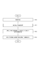
- the overall operation will be described with reference to the flowchart of FIG. 2
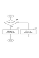
- the meander determination means selection process will be described with reference to the flowchart of FIG. 3
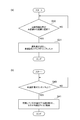
- the vehicle speed range switching threshold learning process will be described with reference to the flowchart of FIG.
- FIG. 2 is a flowchart showing the flow of the main operation.
- FIG. 3 is a flowchart showing the flow of meandering determination means selection processing in the flowchart of the main operation.
- FIG. 4 is a flowchart showing the flow of the learning process of the vehicle speed range switching threshold.
- FIG. 4A is a flowchart of the current vehicle speed storage process
- FIG. 4B is a flowchart of the vehicle speed range switching threshold calculation process.
- the consciousness fall determination system 1 during operation, the following operation is repeated every predetermined time.
- the white line recognition camera 10 captures an area including the road ahead of the vehicle. Then, the white line recognition camera 10 recognizes a pair of left and right white lines indicating the lane in which the vehicle is traveling from the captured image, and from the pair of left and right white lines, the lane width, the center line of the pair of left and right white lines, the curve radius and the curvature. The offset amount from the lane center, the yaw angle with respect to the lane center line, and the like are calculated. Then, the white line recognition camera 10 transmits the white line recognition result and various calculated information to the ECU 30 as a white line recognition signal. The ECU 30 receives the white line recognition signal, and acquires a white line recognition result and various types of information.
- the steering angle sensor 11 detects the steering angle and transmits the detected steering angle to the ECU 30 as a steering angle signal.
- the ECU 30 receives this steering angle signal and acquires the steering angle.
- the vehicle speed sensor 12 detects the vehicle speed and transmits the detected vehicle speed as a vehicle speed signal to the ECU 30 (S10).
- the ECU 30 receives this vehicle speed signal and acquires the vehicle speed.
- the ECU 30 performs meandering determination means selection processing (S11). First, the ECU 30 determines whether or not the vehicle speed is equal to or higher than the vehicle speed range switching threshold Th_S (S20). When it is determined in S20 that the vehicle speed is equal to or higher than Th_S, the ECU 30 selects the white line recognition camera 10 for meander determination (S21). At this time, when the steering angle sensor 11 is not used in the other system 1, the steering angle sensor 11 may be stopped. When it is determined in S20 that the vehicle speed is less than Th_S, the ECU 30 selects the steering angle sensor 11 for meander determination (S22). At this time, when the white line recognition camera 10 is not used in another system, the white line recognition camera 10 may be stopped.
- Th_S vehicle speed range switching threshold
- the ECU 30 determines whether or not there is meandering using the time series data of the offset amount by the white line recognition camera 10 (S12).
- the ECU 30 determines whether or not there has been meandering using the time series data of the steering angle by the steering angle sensor 11 (S12). If the ECU 30 determines that there is meandering, the ECU 30 determines that the driver is in a state of reduced consciousness (turns on the consciousness decrease flag), and transmits an alarm output signal to the alarm device 20 (S13).
- the alarm device 20 When the alarm device 20 receives the alarm output signal, the alarm device 20 outputs an alarm (S13). By this warning, the driver can recognize that his / her consciousness is decreasing, and takes a break or the like as necessary.
- the ECU 30 determines whether or not the white line recognition state has changed from unrecognized to recognition based on the recognition result of the white line recognition camera 10 (S30). Determine again later. If it is determined in S30 that the white line recognition state has changed from unrecognized to recognized, the ECU 30 stores the current vehicle speed detected by the vehicle speed sensor 12 and increments the vehicle speed storage counter (S31).
- the ECU 30 determines whether or not the counter value of the vehicle speed storage counter exceeds Th_C (S40), and determines again after a predetermined time when it is determined that the counter value is equal to or less than Th_C.
- the ECU 30 calculates an average value of the stored vehicle speed and stores the average value in the vehicle speed range switching threshold Th_S (S41). If a learning value has already been stored in Th_S, the learning value may be updated in consideration of the average value of the vehicle speed accumulated this time.
- the vehicle speed range switching vehicle speed is learned based on the accumulated vehicle speed data.
- the meandering determination can be performed using the white line recognition camera 10 in a vehicle speed range where the white line recognition camera 10 can actually recognize the white line.
- the driver when it is determined that there is meandering, it is determined that the driver is in a state of reduced consciousness. May be used in other systems such as an air suspension control system, a lane keep assist system, a tire air pressure warning system, and an alignment deviation warning system. Further, a meandering determination device for determining meandering may be used, and information on meandering may be used in each system.
- the ECU of the consciousness deterioration determination system performs each process of meander determination means selection, meandering presence / absence determination, alarm control, and threshold learning. It is good also as a structure performed with an inside processing device.
- the steering angle is applied as vehicle turning information for determining meandering, and the steering angle sensor is used.
- other parameters such as steering angular velocity and yaw rate may be applied as the turning information.
- a sensor corresponding to each parameter may be used.
- the processing unit that learns the vehicle speed range switching threshold is provided. However, such a learning may not be performed.
- the initial value described in the present embodiment may be used as it is as the vehicle speed range switching threshold, or the driver may set (or select) the vehicle speed of the vehicle speed range switching threshold.
- the present invention is applied to a meandering determination device including a turning information detection unit that detects turning information of a vehicle, and an image recognition detection unit that detects position information of the vehicle with respect to a lane by image recognition on a captured image including a running road. Is possible.
- SYMBOLS 1 Consciousness fall determination system, 10 ... White line recognition camera, 11 ... Rudder angle sensor, 12 ... Vehicle speed sensor, 20 ... Alarm device, 30 ... ECU, 31 ... Meander determination means selection part, 32 ... Meander presence determination part, 33 ... Alarm control unit, 34... Threshold learning unit.
Landscapes
- Engineering & Computer Science (AREA)
- Physics & Mathematics (AREA)
- General Physics & Mathematics (AREA)
- Business, Economics & Management (AREA)
- Emergency Management (AREA)
- Automation & Control Theory (AREA)
- Transportation (AREA)
- Mechanical Engineering (AREA)
- Multimedia (AREA)
- Theoretical Computer Science (AREA)
- Traffic Control Systems (AREA)
- Image Analysis (AREA)
Abstract
Description
Claims (2)
- 車両の旋回情報を検出する旋回情報検出部と、走行中の道路を含む撮像画像に対する画像認識により車線に対する車両の位置情報を検出する画像認識検出部とを備える蛇行判定装置であって、
車速を検出する車速検出部と、
前記車速検出部で検出した車速が所定車速以上の場合には前記画像認識検出部を選択し、前記車速検出部で検出した車速が所定車速未満の場合には前記旋回情報検出部を選択する選択部と、
前記選択部で画像認識検出部を選択した場合に車線に対する車両の位置情報に基づいて車両の蛇行を判定し、前記選択部で旋回情報検出部を選択した場合に車両の旋回情報に基づいて車両の蛇行を判定する蛇行判定部と、
を備えることを特徴とする蛇行判定装置。 - 前記画像認識検出部による車線を認識可能な状態と車線を認識不能な状態とが切り替わるときに前記車速検出部で検出した車速に基づいて前記所定車速を決定する学習部を備えることを特徴とする請求項1に記載の蛇行判定装置。
Priority Applications (5)
| Application Number | Priority Date | Filing Date | Title |
|---|---|---|---|
| PCT/JP2012/061114 WO2013161024A1 (ja) | 2012-04-25 | 2012-04-25 | 蛇行判定装置 |
| DE112012006288.4T DE112012006288B4 (de) | 2012-04-25 | 2012-04-25 | Abdriftbeurteilungsvorrichtung |
| US14/391,018 US9805275B2 (en) | 2012-04-25 | 2012-04-25 | Drift-assessment device |
| JP2014512226A JP5858149B2 (ja) | 2012-04-25 | 2012-04-25 | 蛇行判定装置 |
| CN201280072561.1A CN104246850B (zh) | 2012-04-25 | 2012-04-25 | 蛇行判定装置 |
Applications Claiming Priority (1)
| Application Number | Priority Date | Filing Date | Title |
|---|---|---|---|
| PCT/JP2012/061114 WO2013161024A1 (ja) | 2012-04-25 | 2012-04-25 | 蛇行判定装置 |
Publications (1)
| Publication Number | Publication Date |
|---|---|
| WO2013161024A1 true WO2013161024A1 (ja) | 2013-10-31 |
Family
ID=49482394
Family Applications (1)
| Application Number | Title | Priority Date | Filing Date |
|---|---|---|---|
| PCT/JP2012/061114 Ceased WO2013161024A1 (ja) | 2012-04-25 | 2012-04-25 | 蛇行判定装置 |
Country Status (5)
| Country | Link |
|---|---|
| US (1) | US9805275B2 (ja) |
| JP (1) | JP5858149B2 (ja) |
| CN (1) | CN104246850B (ja) |
| DE (1) | DE112012006288B4 (ja) |
| WO (1) | WO2013161024A1 (ja) |
Cited By (1)
| Publication number | Priority date | Publication date | Assignee | Title |
|---|---|---|---|---|
| JP2018200600A (ja) * | 2017-05-29 | 2018-12-20 | マツダ株式会社 | 運転者状態推定装置 |
Families Citing this family (20)
| Publication number | Priority date | Publication date | Assignee | Title |
|---|---|---|---|---|
| US20080103217A1 (en) | 2006-10-31 | 2008-05-01 | Hari Babu Sunkara | Polyether ester elastomer composition |
| GB0618196D0 (en) | 2006-09-15 | 2006-10-25 | Pursuit Dynamics Plc | An improved mist generating apparatus and method |
| US9421973B2 (en) * | 2014-02-28 | 2016-08-23 | GM Global Technology Operations LLC | Jerk reduction in transition between lane-centering and lane-keeping steering systems |
| JP6341149B2 (ja) * | 2015-07-07 | 2018-06-13 | トヨタ自動車株式会社 | 車両の運転支援装置 |
| US10249185B2 (en) | 2016-08-18 | 2019-04-02 | Amazon Technologies, Inc. | Illuminated signal device and speed detector for audio/video recording and communication devices |
| US11008039B2 (en) * | 2017-04-12 | 2021-05-18 | Toyota Jidosha Kabushiki Kaisha | Lane change assist apparatus for vehicle |
| US10668925B2 (en) * | 2017-09-05 | 2020-06-02 | Baidu Usa Llc | Driver intention-based lane assistant system for autonomous driving vehicles |
| DE102017120899A1 (de) * | 2017-09-11 | 2019-03-14 | Connaught Electronics Ltd. | Verfahren und System zum automatischen Parken eines Fahrzeugs in einer Notsituation |
| CN110084185B (zh) * | 2019-04-25 | 2021-03-16 | 西南交通大学 | 一种高速列车小幅蛇行运行特征的快速提取方法 |
| TWI715238B (zh) * | 2019-10-05 | 2021-01-01 | 宏碁股份有限公司 | 蛇行偵測方法及其裝置 |
| US11383733B2 (en) | 2020-01-31 | 2022-07-12 | Mitac Digital Technology Corporation | Method and system for detecting a dangerous driving condition for a vehicle, and non-transitory computer readable medium storing program for implementing the method |
| CN115123243B (zh) * | 2022-08-09 | 2025-04-25 | 博世汽车部件(苏州)有限公司 | 用于车辆的漂移控制单元、系统和方法 |
| JP7632422B2 (ja) | 2022-09-13 | 2025-02-19 | トヨタ自動車株式会社 | 防曇システム、制御方法 |
| JP7704132B2 (ja) | 2022-11-30 | 2025-07-08 | トヨタ自動車株式会社 | 車両用通知装置 |
| JP7794155B2 (ja) | 2023-03-16 | 2026-01-06 | トヨタ自動車株式会社 | 車両の操舵支援装置 |
| KR20250001039A (ko) * | 2023-06-28 | 2025-01-06 | 주식회사 에이치엘클레무브 | 차로 관련 첨단 운전자 지원 시스템 및 그 제어 방법과, 이를 구비한 차량 |
| JP2025057782A (ja) | 2023-09-28 | 2025-04-09 | トヨタ自動車株式会社 | ふらつき判定装置、ふらつき判定方法及びプログラム |
| JP2025073378A (ja) | 2023-10-26 | 2025-05-13 | トヨタ自動車株式会社 | ドライバ状態判定装置 |
| JP2025092199A (ja) | 2023-12-08 | 2025-06-19 | トヨタ自動車株式会社 | 脇見警告システム |
| CN119821415B (zh) * | 2024-12-24 | 2025-11-18 | 科大讯飞股份有限公司 | 车辆蛇形行驶检测方法、装置、电子设备和存储介质 |
Citations (4)
| Publication number | Priority date | Publication date | Assignee | Title |
|---|---|---|---|---|
| JPH0911773A (ja) * | 1995-06-30 | 1997-01-14 | Mitsubishi Automob Eng Co Ltd | 車両走行状態検出装置及び居眠り運転警報装置 |
| JP2007265101A (ja) * | 2006-03-29 | 2007-10-11 | Mitsubishi Fuso Truck & Bus Corp | 車両用覚醒度推定装置 |
| JP2008021161A (ja) * | 2006-07-13 | 2008-01-31 | Mitsubishi Fuso Truck & Bus Corp | 走行状態判定装置 |
| JP2008152735A (ja) * | 2006-12-20 | 2008-07-03 | Mitsubishi Fuso Truck & Bus Corp | 車両用注意力監視装置 |
Family Cites Families (8)
| Publication number | Priority date | Publication date | Assignee | Title |
|---|---|---|---|---|
| DE102005018697A1 (de) * | 2004-06-02 | 2005-12-29 | Daimlerchrysler Ag | Verfahren und Vorrichtung zur Warnung eines Fahrers im Falle eines Verlassens der Fahrspur |
| JP4564320B2 (ja) * | 2004-09-29 | 2010-10-20 | アイシン精機株式会社 | ドライバモニタシステム |
| JP3925540B2 (ja) * | 2005-03-23 | 2007-06-06 | トヨタ自動車株式会社 | 車両用走行制御装置 |
| JP4654208B2 (ja) * | 2007-02-13 | 2011-03-16 | 日立オートモティブシステムズ株式会社 | 車載用走行環境認識装置 |
| JP5415434B2 (ja) * | 2008-10-02 | 2014-02-12 | 日立オートモティブシステムズ株式会社 | 車両走行に関する情報処理装置 |
| CN101840632B (zh) * | 2009-03-18 | 2013-05-29 | 深圳先进技术研究院 | 一种对车内驾驶行为异常监控方法和系统 |
| CN101872171B (zh) * | 2009-04-24 | 2012-06-27 | 中国农业大学 | 基于信息融合的驾驶员疲劳状态识别方法和系统 |
| CN201566602U (zh) * | 2009-09-25 | 2010-09-01 | 马援 | 一种机动车驾驶员防磕睡紧急自动停车装置 |
-
2012
- 2012-04-25 JP JP2014512226A patent/JP5858149B2/ja active Active
- 2012-04-25 WO PCT/JP2012/061114 patent/WO2013161024A1/ja not_active Ceased
- 2012-04-25 DE DE112012006288.4T patent/DE112012006288B4/de active Active
- 2012-04-25 US US14/391,018 patent/US9805275B2/en active Active
- 2012-04-25 CN CN201280072561.1A patent/CN104246850B/zh active Active
Patent Citations (4)
| Publication number | Priority date | Publication date | Assignee | Title |
|---|---|---|---|---|
| JPH0911773A (ja) * | 1995-06-30 | 1997-01-14 | Mitsubishi Automob Eng Co Ltd | 車両走行状態検出装置及び居眠り運転警報装置 |
| JP2007265101A (ja) * | 2006-03-29 | 2007-10-11 | Mitsubishi Fuso Truck & Bus Corp | 車両用覚醒度推定装置 |
| JP2008021161A (ja) * | 2006-07-13 | 2008-01-31 | Mitsubishi Fuso Truck & Bus Corp | 走行状態判定装置 |
| JP2008152735A (ja) * | 2006-12-20 | 2008-07-03 | Mitsubishi Fuso Truck & Bus Corp | 車両用注意力監視装置 |
Cited By (1)
| Publication number | Priority date | Publication date | Assignee | Title |
|---|---|---|---|---|
| JP2018200600A (ja) * | 2017-05-29 | 2018-12-20 | マツダ株式会社 | 運転者状態推定装置 |
Also Published As
| Publication number | Publication date |
|---|---|
| JPWO2013161024A1 (ja) | 2015-12-21 |
| CN104246850A (zh) | 2014-12-24 |
| US9805275B2 (en) | 2017-10-31 |
| DE112012006288B4 (de) | 2020-09-03 |
| CN104246850B (zh) | 2016-11-09 |
| JP5858149B2 (ja) | 2016-02-10 |
| US20150117714A1 (en) | 2015-04-30 |
| DE112012006288T5 (de) | 2015-01-22 |
Similar Documents
| Publication | Publication Date | Title |
|---|---|---|
| JP5858149B2 (ja) | 蛇行判定装置 | |
| JP5831624B2 (ja) | 意識低下判定システム | |
| US7532981B2 (en) | Vehicle departure detecting device | |
| US9070293B2 (en) | Device and method for traffic sign recognition | |
| CN102376166B (zh) | 用于在机动车辆内识别道路标志的装置和方法 | |
| US8930063B2 (en) | Method for determining object sensor misalignment | |
| JP6410949B2 (ja) | 車線認識装置および車線認識方法 | |
| JP5594246B2 (ja) | 車線認識装置 | |
| US7400236B2 (en) | Vehicular lane monitoring system utilizing front and rear cameras | |
| JP5146243B2 (ja) | 車線逸脱抑制装置 | |
| EP2803546A1 (en) | Collision mitigation apparatus | |
| US10046801B2 (en) | Steering assist control apparatus and steering assist control method | |
| US20140129084A1 (en) | Control apparatus of vehicle for changing lane and control method of the same | |
| US20150149076A1 (en) | Method for Determining a Course of a Traffic Lane for a Vehicle | |
| JP2009116527A (ja) | 車両用障害物検出装置 | |
| JP2015162228A (ja) | 車両用制御装置 | |
| CN105579316A (zh) | 用于确定车辆的行车道的行车道走向的方法和设备 | |
| CN103847736A (zh) | 车道线识别系统 | |
| JP4876772B2 (ja) | 割込車両判定装置 | |
| JP2015221636A (ja) | 車線維持支援装置 | |
| JP4225182B2 (ja) | 居眠り運転予防装置 | |
| CN116691493B (zh) | 一种车辆变道预警方法及相关设备 | |
| US12246716B2 (en) | Control device of vehicle, control method, and storage medium | |
| JP7430445B2 (ja) | 通行道路変更判定装置 | |
| JP2008114731A (ja) | 目標物監視装置、及び目標物監視方法 |
Legal Events
| Date | Code | Title | Description |
|---|---|---|---|
| 121 | Ep: the epo has been informed by wipo that ep was designated in this application |
Ref document number: 12875515 Country of ref document: EP Kind code of ref document: A1 |
|
| ENP | Entry into the national phase |
Ref document number: 2014512226 Country of ref document: JP Kind code of ref document: A |
|
| WWE | Wipo information: entry into national phase |
Ref document number: 14391018 Country of ref document: US |
|
| WWE | Wipo information: entry into national phase |
Ref document number: 1120120062884 Country of ref document: DE Ref document number: 112012006288 Country of ref document: DE |
|
| 122 | Ep: pct application non-entry in european phase |
Ref document number: 12875515 Country of ref document: EP Kind code of ref document: A1 |