WO2013157356A1 - マスクユニット及び基板処理装置 - Google Patents
マスクユニット及び基板処理装置 Download PDFInfo
- Publication number
- WO2013157356A1 WO2013157356A1 PCT/JP2013/058686 JP2013058686W WO2013157356A1 WO 2013157356 A1 WO2013157356 A1 WO 2013157356A1 JP 2013058686 W JP2013058686 W JP 2013058686W WO 2013157356 A1 WO2013157356 A1 WO 2013157356A1
- Authority
- WO
- WIPO (PCT)
- Prior art keywords
- mask
- substrate
- axis
- unit
- holding
- Prior art date
- Legal status (The legal status is an assumption and is not a legal conclusion. Google has not performed a legal analysis and makes no representation as to the accuracy of the status listed.)
- Ceased
Links
Images



Classifications
-
- G—PHYSICS
- G03—PHOTOGRAPHY; CINEMATOGRAPHY; ANALOGOUS TECHNIQUES USING WAVES OTHER THAN OPTICAL WAVES; ELECTROGRAPHY; HOLOGRAPHY
- G03F—PHOTOMECHANICAL PRODUCTION OF TEXTURED OR PATTERNED SURFACES, e.g. FOR PRINTING, FOR PROCESSING OF SEMICONDUCTOR DEVICES; MATERIALS THEREFOR; ORIGINALS THEREFOR; APPARATUS SPECIALLY ADAPTED THEREFOR
- G03F7/00—Photomechanical, e.g. photolithographic, production of textured or patterned surfaces, e.g. printing surfaces; Materials therefor, e.g. comprising photoresists; Apparatus specially adapted therefor
- G03F7/20—Exposure; Apparatus therefor
- G03F7/24—Curved surfaces
Definitions
- the present invention relates to a mask unit and a substrate processing apparatus.
- This application claims priority based on Japanese Patent Application No. 2012-095894 for which it applied on April 19, 2012, and uses the content here.
- a transparent electrode such as ITO (Indium Tin Oxide) or a semiconductor material such as Si is deposited on a flat glass substrate, and then a metal material is evaporated to form a photoresist. Is applied to transfer the circuit pattern. Then, after developing the photoresist, a circuit pattern or the like is formed by etching.
- a roll-to-roll method (hereinafter simply referred to as “roll method”) in which a display element is formed on a flexible substrate (for example, a film member such as polyimide, PET, metal foil, or an ultrathin glass sheet).
- a technique called “notation” has been proposed (see, for example, Patent Document 1).
- Patent Document 2 a flexible long sheet (substrate) that is wound around a feed roller and traveled is disposed in the vicinity of the outer peripheral portion of a rotatable cylindrical mask, and the mask pattern is continuous.
- techniques for exposing a substrate have been proposed.
- the shape of the underlying pattern layer region on the sheet may be distorted nonlinearly, and the mask pattern on the cylindrical mask and the sheet (substrate) Relative alignment becomes even more difficult.
- the tension applied to the sheet when it is wound around the rotating drum varies greatly depending on the sheet thickness, Young's modulus, friction coefficient, and the like. Sometimes. Therefore, the extension amount of the sheet also varies depending on the thickness.
- the sheet to which tension is applied is wound in a stretched state on the rotating drum during exposure, and after the exposure is completed, the contact with the rotating drum is released.
- the dimension in the longitudinal direction of the mask pattern forming area exposed and transferred onto the sheet is slightly shrunk after the tension is released.
- the expansion amount shrinkage amount
- the dimension of the formation area of the mask pattern transferred onto the sheet varies depending on the sheet thickness. In particular, when manufacturing a display panel for a large display, it is desired that the variation in the area size of the display panel pattern formed on the sheet is as small as possible.
- An object of an aspect of the present invention is to provide a mask unit and a substrate processing apparatus that can easily adjust the relative positional relationship between a mask pattern and a substrate.
- the mask pattern is held along the cylindrical surface having a predetermined radius from the first axis, and the mask holding unit rotatable around the first axis, and the mask holding unit are arranged in the first direction.
- a support portion that is movably supported in a non-contact or low-friction state in a direction around the first axis and in a first axis direction, and provided on both sides of the mask holding portion in the first axial direction.
- a mask unit is provided that includes a pair of drive units that are driven by applying thrust in the direction around the axis.
- a substrate processing apparatus including the mask unit according to the first aspect of the present invention and a substrate holding unit for holding a substrate onto which a mask pattern is transferred.
- a substrate processing apparatus for transferring a mask pattern onto a photosensitive substrate, the mask holding the mask pattern along a cylindrical surface having a predetermined radius from the first axis.
- the pattern holding portion is provided on each of both sides of the mask pattern holding portion in the first axis direction, and is supported on the mask pattern holding portion around the first axis.
- a substrate processing apparatus including a pair of driving units that apply a driving force in a direction.
- the relative positional relationship between the mask pattern and the substrate can be easily adjusted, and the mask pattern can be formed on the substrate with high accuracy.
- FIG. 1 is a schematic external perspective view of a substrate processing apparatus according to an embodiment. It is sectional drawing which fractured
- FIG. 1 is a schematic external perspective view of a substrate processing apparatus 100 including a rotatable cylindrical mask unit MU and a sheet (substrate) S holding unit SU.
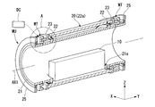
- FIG. 2 is a cross-sectional view of the cylindrical mask unit MU in FIG. 1 cut along a plane including the rotation axis AX1.
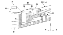
- FIG. 3 is an enlarged view of portion A in FIG.
- the substrate processing apparatus 100 performs an exposure process on a strip-shaped substrate (for example, a strip-shaped film member) S with a flexible sheet-like mask M pattern.
- the substrate processing apparatus 100 mainly includes an illumination unit 10 (not shown in FIG. 1, refer to FIG. 2), a mask unit MU, a substrate holding unit SU, and a control unit (not shown).
- an XYZ axis coordinate system is set as shown in FIG. 1, and the following description will be given using this XYZ axis coordinate system as appropriate.
- the vertical direction is the Z axis direction
- the direction parallel to the rotation axes AX1 and AX2 of the mask unit MU and the substrate holding unit SU is the Y axis direction
- the direction will be described as the X-axis direction.
- the illumination unit 10 irradiates illumination light toward an illumination area of the mask M wound around a mask holding unit 20 (described later) in the mask unit MU.
- the illuminating unit 10 is a straight tube type that emits exposure illumination light radially like a fluorescent lamp, or a diffusing member is provided on the back side by introducing illumination light from both ends of a cylindrical quartz rod. Those used are accommodated in the internal space of the inner cylinder 21 that supports the mask holding portion 20.
- the mask unit MU includes a mask holding unit 20 (also referred to as a mask pattern holding unit), an inner cylinder 21, a holder 23, a drive unit MT, and an impression cylinder installation unit 25.
- the mask holding part 20 and the holder 23 are provided in an integrated state. Further, the mask holding unit 20 and the holder 23 communicate with each other in the direction of the rotation axis AX1, and are formed with through holes through which the inner cylinder 21 is inserted.
- the mask holding unit 20 is formed of a cylindrical transparent substrate (quartz or the like) that can transmit illumination light.
- a mask holding surface 22 a that holds the mask M along a cylindrical surface having a predetermined radius is formed on the outer peripheral surface of the mask holding unit 20.
- the mask M is preferably obtained by directly depositing a light-shielding film such as chromium on the mask holding surface 22a.
- a configuration may be adopted in which an extremely thin glass sheet having a pattern formed of a light-shielding film is tightly wound around the mask holding surface 22a.
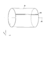
- the mask holding unit 20 is generally cylindrical with a predetermined thickness. However, as shown in FIG. 1, when the mask M is held, a slit 20S parallel to the axis AX1 is formed in a part around the rotation axis AX1. Specifically, as shown in FIG. 4, a slit 20S is provided in the circumferential direction of the mask holding unit 20 with a width of, for example, about 1 to several mm from which a part of the mask holding unit 20 is removed.
- the slot 20S does not necessarily have to be parallel to the rotation axis AX1, and may be inclined. Further, the slit 20S does not need to be linear, and may be a gentle arc shape or a zigzag shape.
- the mask M (mask pattern) is held on the mask holding surface 22a while avoiding the slit 20S, the mask M (mask pattern) is discontinuous with respect to the cylindrical circumferential direction. That is, the peripheral surface of the mask holding part 20 has a circumference that holds the mask M with the two ends in the direction around the rotation axis AX1 being spaced apart.
- the mask holding portion 20 is rotated about the axis of rotation AX1 by an air pad (support portion) 22 (details will be described later) which is a fluid bearing provided at a position facing the inner peripheral surface of the inner cylinder 21, or a high-precision ball bearing. It is supported so as to be movable with respect to the inner cylinder 21 in a stationary state in a non-contact state or a low friction state in the direction and the direction around the rotation axis AX1.
- the air pad (support portion) 22 includes a fluid bearing.
- the holder 23 is formed in an annular shape with a metal material. As shown in FIG. 3, the holder 23 holds the outer peripheral surface and inner peripheral surface of the end portion of the mask holding unit 20.
- the drive part MT gives the thrust which drives the mask holding
- the drive unit MT is provided in pairs on both sides of the mask holding unit 20 in the direction of the rotation axis AX1.
- Each drive unit MT is configured by, for example, a voice coil motor that applies thrust in two directions of the rotation axis AX1 and the direction around the rotation axis AX1, and includes a magnet generator MG and a coil body CU. .
- the direction should just be able to provide only one among a pair of drive parts MT.
- the magnetomotive member MG is provided on the outer surface of the holder 23 in the Y-axis direction so as to extend in the direction of the rotation axis AX1 over the entire circumference in the direction around the rotation axis AX1.
- the coil body CU is fixed to the outer peripheral surface of the inner cylinder 21 over the entire circumference, and has a U-shaped cross-sectional shape that sandwiches the magnetomotive body MG in the radial direction about the rotation axis AX1. Energization of the coil body CU is controlled by the drive control unit DC.
- the magnet generator MG is not necessarily provided over the entire circumference, and a plurality of magnet generators MG may be provided with a predetermined interval in the circumferential direction (for example, a configuration in which three locations are provided at intervals of 120 °).
- the impression cylinder installation portions 25 are provided at both ends in the direction of the rotation axis AX1 of the inner cylinder 21 so as to be rotatable in the direction around the rotation axis AX1 via the air bearings 26, respectively.
- the outer diameter of the impression cylinder installation portion 25 is formed to be a predetermined amount larger than the outer diameter formed by the outer surface of the mask M held on the mask holding surface 22 a of the mask holding portion 20.
- the outer diameter of the impression cylinder installation part 25 is held by the impression cylinder 30 when the impression cylinder installation part 25 abuts on the outer peripheral surface of the impression cylinder 30 and the mask holding part 20 is supported at a predetermined position.
- a predetermined amount of proximity gap is formed between the substrate S and the mask M formed.
- the ring-shaped impression cylinder installation portion 25 that is in contact with the outer peripheral surface of the impression cylinder 30 rolls around the inner cylinder 21 due to friction.
- the inner cylinder 21 is installed at a base portion of the apparatus main body (not shown).
- the inner cylinder 21 rotatably supports the impression cylinder installation portion 25 via air bearings 26 at both ends in the direction of the rotation axis AX1, and a mask holding portion 20.
- An air pad 22 is provided on the outer peripheral surface opposite to the inner peripheral surface of the.
- the air pad 22 is formed of, for example, a porous pad.
- the air pad 22 is formed on the outer peripheral surface on both sides of the inner cylinder 21 in the direction of the rotation axis AX1 facing the inner peripheral surface of the mask holding unit 20 and on the entire circumference in the direction around the rotation axis AX1. Or, it is provided at a plurality of locations spaced apart in the direction around the rotation axis AX1.
- the mask unit MU including the mask holding unit 20, the inner cylinder 21, the holder 23, the drive unit MT, the impression cylinder installation unit 25, and the illumination unit 10 are converted into an illumination unit by the turning drive unit (moving unit) SC shown in FIG. 1.
- the illumination light from 10 can turn (revolve) a small amount around the rotation axis AX2 in a state where the posture toward the rotation axis AX2 of the impression body 30 is maintained.
- the substrate holding unit SU includes an impression body (substrate holding unit) 30.
- the impression body 30 is formed in a columnar shape that is parallel to the Y axis and rotates around a rotation axis (second axis) AX2 set on the ⁇ Z axis side of the rotation axis AX1.
- the outer peripheral surface of the impression body 30 is a substrate holding surface 31 that holds the substrate S in contact therewith.
- rotation support portions 32 having a smaller diameter than the impression body 30 and projecting coaxially are supported on the base portion of the apparatus main body so as to be rotatable around the rotation axis AX2.
- a driving device (motor or the like) 33 for rotating the impression body 30 is provided.
- the drive device 33 is controlled by the drive control unit DC described above.
- the impression body 30 is controlled to be rotated at a constant angular speed by the driving device 33 to feed the substrate S at a constant speed, and the cylindrical mask holding portion 20 (holder 23) of the mask holding unit MU is Servo control (follow-up control) is performed on the drive units MT on both sides so that the peripheral speed of the mask pattern surface becomes a rotational speed corresponding to the feed speed of the substrate S.
- the substrate processing apparatus 100 configured as described above, when the pattern of the mask M is exposed on the substrate S, it is necessary to adjust image shift, image rotation, image magnification, and the like in order to cope with expansion and contraction, distortion, and the like of the substrate S. .
- the mask holding unit 20 holds the mask M along the cylindrical surface, the image shift and the image magnification adjustment need to be performed individually in the direction of the rotation axis AX1 and the direction around the rotation axis AX1.
- Each adjustment amount is a position measurement value such as an alignment mark on the mask M detected using an alignment microscope or the like, or a reading value such as an encoder scale formed in advance on the outer peripheral surface of the mask holding unit 20 or the impression body 30.
- a position measurement value such as an alignment mark on the mask M detected using an alignment microscope or the like
- a reading value such as an encoder scale formed in advance on the outer peripheral surface of the mask holding unit 20 or the impression body 30.
- the image shift in the present embodiment means that the mask pattern held in a cylindrical shape is finely moved in the Y-axis direction in which the rotation axis AX1 extends as a whole with respect to the substrate S, or the cylindrical mask pattern and the pressure The relative position in the rotational circumferential direction with respect to the substrate S wound around the body 30 is finely moved.
- the image shift adjustment in the direction of the rotation axis AX1 is performed by moving the holder 23 and the mask holding unit 20 (mask M) in the direction of the rotation axis AX1 via the magnetic generator MG of the drive unit MT by energization control of the drive control unit DC. This is done by moving the
- the holder 23 and the mask holding unit 20 are placed on each of the pair of drive units MT by the energization control of the drive control unit DC.
- the same thrust in the direction around the rotation axis AX1 is applied, and the circumferential position of the mask holding portion 20 (pattern surface of the mask M) is set to a predetermined amount with respect to the longitudinal transfer position of the substrate S by the rotation of the impression body 30. This is done only by fine movement.
- Image rotation in the present embodiment refers to a part of a mask pattern that faces a substrate S held in a cylindrical shape through a predetermined proximity gap, and is slightly rotated (tilted) around the Z axis in the XY plane of FIG. ).
- the adjustment of the image rotation is performed when the holder 23 and the mask holding unit 20 (mask M) are rotated in the direction around the rotation axis AX1 through the magnetic generator MG of the drive unit MT by energization control of the drive control unit DC. This is done by making the thrust characteristics different between the pair of drive parts MT.
- the mask M is rotated in the direction around the rotation axis AX1. Since the (mask holding part 20) is separated by the slit 20S shown in FIG. 4, the mask pattern rotates with the mask M slightly twisted. Accordingly, the mask M (mask holding unit 20) is twisted in accordance with the image rotation adjustment amount, and the mask pattern at the exposure position (illumination light irradiation region) is slightly tilted in the XY plane by the amount to be adjusted. , And can be rotated around the rotation axis AX1. Thereby, the image rotation is adjusted.
- the image magnification adjustment (magnification adjustment in the scanning exposure direction) around the rotation axis AX1 is performed by energization control of the drive control unit DC via the magnet generator MG of the drive unit MT and the mask holding unit 20 ( It is adjusted by the rotational speed when the mask M) is rotated around the rotation axis AX1. That is, by slightly reducing the rotational speed of the mask M (the peripheral speed of the pattern surface) relative to the feed speed of the substrate S, the mask pattern is enlarged and transferred onto the substrate S at a magnification according to the speed ratio, The rotational speed of the mask M can be slightly increased with respect to the feeding speed of the substrate S. As a result, the mask pattern is reduced and transferred onto the substrate S at a magnification according to the speed ratio.
- image magnification adjustment in the direction of the rotation axis AX1 (magnification adjustment in the non-scanning exposure direction) is difficult when the substrate S is sent in close contact with a part of the outer peripheral surface of the impression body 30, as shown in FIG.
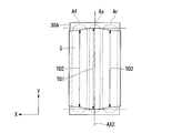
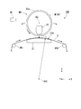
- a cylindrical body 30A made of a porous material such as ceramics is provided on the outer peripheral portion of the impression body 30, and the compressed gas Pa is ejected from the inside of the impression cylinder 30 to the outer circumference through the cylindrical body 30A. If a configuration such as a turn bar (air bearing) is used, the magnification in the non-scanning exposure direction can be adjusted.
- the substrate S when the substrate S is transported in the state of being wound around the upper half of the Z-axis direction of the cylindrical body 30A such as an air bearing, the substrate S hardly contacts the surface of the cylindrical body 30A.
- the paper is folded and conveyed with predetermined tensions T1 and T2.
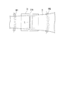
- the state of FIG. 5 is seen in the XY plane in the region As near the vertex in the Z-axis direction of the cylindrical body 30A and the regions Af and Ar in the transport direction of the substrate S with respect to the region As.
- the width in the Y-axis direction of the substrate S changes due to the influences of the tensions T1 and T2, such as the width TD2 in the regions Af and Ar and the width TD1 (TD1> TD2) in the region As.
- the width TD1 of the substrate S is the widest, and in the regions Af and Ar deviating from the region As, it is stretched in the longitudinal direction by the longitudinal tensions T1 and T2. However, it shrinks in the short direction.
- the mask unit MU is swung (revolved) around the rotation axis AX2 by the swivel drive unit SC.
- magnification adjustment (corresponding to expansion / contraction) in the non-scanning exposure direction becomes possible.
- a correlation between the angular position in the direction around the rotation axis AX2 and the amount of change (shrinkage) of the width of the substrate S is obtained in advance from the region Af to the region Ar, and the rotation adjustment unit SC adjusts the magnification adjustment amount.
- the transfer magnification is also adjusted in the direction of the rotation axis AX1 (AX2).
- the drive unit 33 is driven to synchronize with the rotation of the mask holding unit 20 around the rotation axis AX1 by the drive of the drive unit MT.
- the impression body 30 is rotated around the rotation axis AX2.
- illumination light is projected from the illumination part 10, it will permeate
- the mask holding unit 20 is supported by the air pad 22 in a non-contact manner, and the mask holding unit 20 is driven by the driving unit MT to transfer the mask pattern to the substrate S. Adjust image shift, image rotation, and image magnification. Therefore, the relative positional relationship between the mask pattern and the substrate S can be adjusted easily and smoothly.
- the outer peripheral surface of the mask holding unit 20 is set to a circumferential length separated by the slit 20S around a part of the rotation axis AX1 of the mask M, and thus the rotation axis AX1 of the pair of drive units MT.
- image rotation inclination in the XY plane
- the image magnification in the direction of the rotation axis AX1 can be easily adjusted by a simple operation of turning (revolving) the mask unit MU around the rotation axis AX2.
- vibration components in a relatively high frequency range severe Hz or more
- the order of microns generated in the apparatus main body are passed through the inner cylinder 21 through the mask holding unit 20.
- a relatively high frequency range severe Hz or more
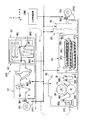
- FIG. 7 is a diagram showing a partial configuration of a device manufacturing system (flexible display manufacturing line) SYS.
- the flexible substrate P sheet, film, etc. drawn out from the supply roll FR1 is sequentially passed through n processing devices U1, U2, U3, U4, U5,... Un to the collection roll FR2.
- An example of winding up is shown.
- the host control device CONT performs overall control of the processing devices U1 to Un constituting the production line.
- the orthogonal coordinate system XYZ is set so that the front surface (or back surface) of the substrate P is perpendicular to the XZ axis surface, and the width direction orthogonal to the transport direction (long direction) of the substrate P is the Y axis direction.
- the substrate P may be activated by modifying the surface in advance by a predetermined pretreatment, or may be formed with a fine partition structure (uneven structure) for precise patterning on the surface.
- the substrate P wound around the supply roll FR1 is pulled out by the nipped drive roller DR1 and conveyed to the processing apparatus U1.
- the center of the substrate P in the Y-axis direction (width direction) is servo-controlled by the edge position controller EPC1 so as to be within a range of about ⁇ 10 ⁇ m to several tens ⁇ m with respect to the target position.
- the processing apparatus U1 applies a photosensitive functional liquid (photoresist, photosensitive silane coupling material (eg, photosensitive silane coupling material), UV curable resin liquid, etc.) to the surface of the substrate P by a printing method. It is a coating device that applies continuously or selectively in the transport direction (long direction).
- a coating mechanism including a pressure drum DR2 around which the substrate P is wound, and a coating roller for uniformly coating the photosensitive functional liquid on the surface of the substrate P on the pressure drum DR2.
- Gp1 a drying mechanism Gp2 for rapidly removing a solvent or moisture contained in the photosensitive functional liquid applied to the substrate P, and the like are provided.
- the processing device U2 heats the substrate P conveyed from the processing device U1 to a predetermined temperature (for example, about several tens of degrees Celsius to 120 ° C.) to stably fix the photosensitive functional layer applied on the surface. It is a heating device.
- a predetermined temperature for example, about several tens of degrees Celsius to 120 ° C.
- a heating chamber HA1 for heating the substrate P that has been carried in, and the temperature of the heated substrate P are as follows:
- a cooling chamber HA2 and a nipped drive roller DR3 are provided for lowering the temperature so as to match the ambient temperature of the post-process (processing device U3).
- the processing apparatus U3 as the substrate processing apparatus 100 applies ultraviolet patterning light corresponding to the circuit pattern or wiring pattern for display to the photosensitive functional layer of the substrate P (substrate S) conveyed from the processing apparatus U2.
- An exposure apparatus for irradiation In the processing apparatus U3, an edge position controller EPC for controlling the center of the substrate P in the Y-axis direction (width direction) to a fixed position, the nipped drive roller DR4, and the substrate P are partially wound with a predetermined tension, A rotary drum DR5 (impression body 30) for supporting a pattern exposed portion on the substrate P in a uniform cylindrical surface, and two sets of driving rollers DR6 for giving a predetermined slack (play) DL to the substrate P , DR7, etc. are provided.
- a transmission type cylindrical mask DM (mask unit MU) and an illumination mechanism IU (illumination) provided in the cylindrical mask DM and illuminating a mask pattern formed on the outer peripheral surface of the cylindrical mask DM.
- Part 10 a transmission type cylindrical mask DM (mask unit MU) and an illumination mechanism IU (illumination) provided in the cylindrical mask DM and illuminating a mask pattern formed on the outer peripheral surface of the cylindrical mask DM.
- Part 10 a part of the substrate P supported in a cylindrical surface by the rotary drum DR5
- Alignment microscopes AM1 and AM2 for detecting an alignment mark or the like formed in advance on P are provided.
- the processing device U4 is a wet processing device that performs wet development processing, electroless plating processing, and the like on the photosensitive functional layer of the substrate P conveyed from the processing device U3.
- the processing apparatus U4 there are provided three processing tanks BT1, BT2, BT3 layered in the Z-axis direction, a plurality of rollers for bending and transporting the substrate P, a nipped drive roller DR8, and the like. .
- the processing apparatus U5 is a heating and drying apparatus that warms the substrate P transported from the processing apparatus U4 and adjusts the moisture content of the substrate P wetted by the wet process to a predetermined value, but the details are omitted.
- the substrate P that has passed through several processing devices and passed through the last processing device Un in the series of processes is wound up on the collection roll FR2 via the nipped drive roller DR1.
- the drive roller DR1 and the recovery roll are driven by the edge position controller EPC2 so that the center of the substrate P in the Y-axis direction (width direction) or the substrate end in the Y-axis direction does not vary in the Y-axis direction.
- the relative position of the FR2 in the Y-axis direction is successively corrected and controlled.
- the substrate processing apparatus 100 described above is used as the processing apparatus U3. Therefore, the relative positional relationship between the mask pattern and the substrate S can be adjusted easily and smoothly, and a device on which the pattern is formed with high accuracy can be manufactured.
- the image magnification (transfer magnification) adjustment in the direction of the rotation axis AX1 (AX2) is configured to use contraction in the width direction of the substrate S caused by the application of tension to the substrate S.
- the present invention is not limited to this.
- an expander roller (widening portion) ER that widens (extends) the substrate S by a predetermined amount in the width direction may be used.
- a substrate holding portion 31 having a convex cylindrical air pad surface 31A centering on an axis AX3 parallel to the Y-axis direction as a substrate holding surface is provided.
- expander rollers (widening portions) ER1 and ER2 that widen the substrate S by a predetermined amount in the width direction are provided on the upstream side and the downstream side of the substrate holding unit 31 in the transport direction of the substrate S.
- the width of the substrate S is continuously changed on the air pad surface 31A according to the tension applied by the expander rollers ER1 and ER2.
- the relative ratio between the length of the Y-shaped exposure area (illumination area of the mask pattern) L in the Y-axis direction and the width of the substrate S in the Y-axis direction can be finely adjusted. Therefore, as a result, the transfer magnification in the direction of the rotation axis AX1 of the pattern formed on the substrate S can be adjusted.
- the contact resistance between the impression body 30 and the substrate S may be reduced.
- the substrate S when the substrate S is held by the cylindrical body 30A on the outer periphery of the impression body 30, the substrate S can be widened.
- An expander roller ER that widens the substrate S by a predetermined amount in the width direction is provided downstream of the body 30 (cylindrical body 30A) in the conveyance direction of the substrate S, and a position corresponding to the width (magnification) of the substrate S (direction around the axis AX2)
- the image magnification with respect to the direction of the rotation axis AX1 (AX2) may be adjusted by moving the mask unit MU to the position).
- the exposure apparatus as the substrate processing apparatus described in each embodiment is a proximity exposure system in which the mask pattern held by the mask unit MU and the substrate S face each other with a certain gap.
- the present invention is not limited to this, and the same applies even to a method in which an image of a mask pattern held in the mask unit MU is projected and exposed onto the substrate S by an equal magnification projection optical system or an enlarged projection optical system. Is possible.
- the drive part MT provided in the both end sides of the mask (mask pattern) holding part 20 of the mask unit MU is configured as a non-contact type rotary motor in which the coil body CU and the magnet generator MG are opposed to each other.
- a non-contact type rotary motor in which the coil body CU and the magnet generator MG are opposed to each other.
- a plurality of magnets are arranged and a constant magnetic pattern (passive side magnetic gear) is provided on the entire circumference, and thrust is made to face the magnetic pattern.
- a magnetic gear serving as a shaft may be provided.
- the magnetic gear transmits the rotational force in a non-contact manner.
- the magnetic gear on the thrust shaft side is rotated by a normal DC motor, gear motor, or the like, the magnetic gear on the passive side rotates accordingly.
- the mask (mask pattern) holding unit 20 of the mask unit MU is formed of a cylindrical transparent base material (quartz or the like), and the mask pattern is included in the illumination light from the illumination unit 10 inside.
- the transmissive cylindrical mask pattern uses the transmitted light for exposure of the substrate S, it may be a reflective cylindrical mask pattern. In that case, since it is not necessary to provide the illumination part 10 inside a cylindrical mask pattern, the mask (mask pattern) holding
- the rotation control characteristics can be achieved by providing the drive units MT on both sides in the rotation axis direction. In particular, responsiveness can be improved. Furthermore, if the mask (mask pattern) holding part 20 is made of a metal hollow cylindrical base material and a slit (20S) is provided on a part thereof, the mask unit MU can be reduced in weight and the same as in the previous embodiments. In addition, the mask (mask pattern) holding unit 20 can be slightly twisted.
- DESCRIPTION OF SYMBOLS 20 ... Mask holding part, 22 ... Air pad (support part, fluid bearing), 30 ... Impression body (substrate holding part), 100 ... Substrate processing apparatus, AX1 ... Rotating axis (first axis), AX2 ... Rotating axis (first) 2 axis), DC ... drive control unit, ER expander roller (widening unit), MT ... drive unit, MU ... mask unit, SC ... swivel drive unit (moving unit)
Landscapes
- Physics & Mathematics (AREA)
- General Physics & Mathematics (AREA)
- Exposure And Positioning Against Photoresist Photosensitive Materials (AREA)
- Container, Conveyance, Adherence, Positioning, Of Wafer (AREA)
Abstract
Description
本願は、2012年4月19日に出願された日本国特願2012-095894号に基づき優先権を主張し、その内容をここに援用する。
一般的に、可撓性の長尺シートの一部をローラに巻き付けて長尺方向に送る場合、シートには長尺方向に比較的大きなテンション(張力)が作用する為、長尺方向の伸びが生じ得る。一方で、円筒状のマスクの周長方向の寸法はほぼ一定である。そのため、円筒マスクの外周面(パターン面)の周速度と、シートの送りローラ(又は回転ドラム)に巻きついた部分での周速度とを一致させたとしても、シート上に既に形成された下地パターン層も長尺方向に伸びてしまう。したがって、円筒マスク上のパターンを下地パターン層に対して精密に重ね合せることが難しくなる。
図1は、回転可能な円筒マスクユニットMUと、シート(基板)Sの保持ユニットSUと、を含む基板処理装置100の概略的な外観斜視図である。図2は、図1中の円筒マスクユニットMUを、その回転軸線AX1を含む平面で破断した断面図である。図3は、図2におけるA部を拡大した図である。
従って、マスクM(マスクパターン)は、そのスリ割り20Sを避けてマスク保持面22a上に保持される為、円筒周方向に関して非連続なものとなる。すなわち、マスク保持部20の周面は、マスクMを回転軸線AX1周り方向の両端部を離間させて保持する周長を有している。
圧胴体30は、Y軸と平行で、回転軸線AX1の-Z軸側に設定された回転軸線(第2の軸線)AX2回りに回転する円柱状に形成されている。圧胴体30の外周面は、基板Sを接触保持する基板保持面31とされている。圧胴体30のY軸方向の両端面には、圧胴体30よりも小径、且つ同軸で突出する回転支持部32が、装置本体のベース部に回転軸線AX2回りに回転自在に支持されている。また、本実施形態では、圧胴体30を回転駆動させる駆動装置(モータ等)33が設けられている。駆動装置33は、上述した駆動制御部DCによって制御される。
本実施形態における像シフトとは、円筒状に保持されるマスクパターンを、基板Sに対して全体的に回転軸線AX1が延びるY軸方向に微動させること、或いは、円筒状のマスクパターンと、圧胴体30に巻きついた基板Sとの回転周方向に関する相対位置を微動させることである。
本実施形態における像回転とは、円筒状に保持される基板Sと所定のプロキシミティ・ギャップを介して対向するマスクパターンの一部分を、図1のXY面内においてZ軸回りに微小回転(傾斜)させることである。
この像回転の調整は、駆動制御部DCの通電制御により駆動部MTの発磁体MGを介して、ホルダ23及びマスク保持部20(マスクM)を、回転軸線AX1周り方向に回転させる際に、一対の駆動部MTの間で推力特性を異ならせることで行われる。具体的には、一対の駆動部MTの間で異なる推力(回転トルク)でホルダ23及びマスク保持部20(マスクM)を回転軸線AX1周り方向に回転させると、回転軸線AX1周り方向でマスクM(マスク保持部20)が、図4に示したスリ割り20Sによって離間しているため、マスクMが僅かに捻れた状態でマスクパターンが回転する。従って、像回転の調整量に応じてマスクM(マスク保持部20)を捻ることで露光位置(照明光の照射領域)におけるマスクパターンを調整すべき量だけXY面内で微小に傾けた状態で、回転軸線AX1の回りに回転させることができる。これにより、像回転が調整される。
本実施形態における回転軸線AX1周り方向の像倍率調整(走査露光方向の倍率調整)は、駆動制御部DCの通電制御により駆動部MTの発磁体MGを介して、ホルダ23及びマスク保持部20(マスクM)を回転軸線AX1周り方向に回転させる際の回転速度によって調整される。すなわち、マスクMの回転速度(パターン面の周速度)を基板Sの送り速度に対して僅かに小さくすることにより、速度比に応じた倍率でマスクパターンが拡大されて基板S上に転写され、マスクMの回転速度を基板Sの送り速度に対して僅かに大きくすることができる。これにより、速度比に応じた倍率でマスクパターンが縮小されて基板S上に転写される。
この場合、円筒体30AのZ軸方向の頂点近辺の領域Asと、その領域Asに対して、基板Sの搬送方向の前後の領域Af、Arとでは、図5の状態をXY面内で見た図6に示すように、基板SのY軸方向の幅がテンションT1、T2の影響によって、領域Af、Arでは幅TD2、領域Asでは幅TD1(TD1>TD2)のように変化する。
即ち、円筒体30Aの頂点近辺の領域Asでは、基板Sの幅TD1が最も広く、その領域Asから外れた領域Af、Arでは、長尺方向のテンションT1、T2により、長尺方向に伸張しつつ短尺方向に縮むことになる。
しかしながら、比較的高い周波数域の振動が、解像線幅や重ね合せ精度のスペック等の観点から無視できる場合は、機械的な接触はあるものの低摩擦なボールベアリング等で支持しても良い。その場合、マスク保持部20の内周面でボールベアリングのボールと接触し得る部分には、金属製の薄いベルト材等を貼り付けておくのが望ましい。
次に、上記の基板処理装置100を備えたデバイス製造システムについて、図7を参照して説明する。
図7は、デバイス製造システム(フレキシブル・ディスプレー製造ライン)SYSの一部の構成を示す図である。ここでは、供給ロールFR1から引き出された可撓性の基板P(シート、フィルム等)が、順次、n台の処理装置U1,U2,U3,U4,U5,…Unを経て、回収ロールFR2に巻き上げられるまでの例を示している。上位制御装置CONTは、製造ラインを構成する各処理装置U1~Unを統括制御する。
Claims (11)
- 第1の軸線から所定半径の円筒面に沿ってマスクパターンを保持し、前記第1の軸線周りに回転可能なマスク保持部と、
前記マスク保持部を前記第1の軸線周り方向及び前記第1の軸線方向に、非接触状態若しくは低摩擦状態で移動自在に支持する支持部と、
前記マスク保持部の前記第1の軸線方向の両側に設けられ、前記マスク保持部に前記第1の軸線周り方向の推力を与えて駆動させる一対の駆動部と、
を備えるマスクユニット。 - 前記一対の駆動部の少なくとも一方は、前記マスク保持部に前記第1の軸線方向の推力を与える
請求項1に記載のマスクユニット。 - 前記一対の駆動部による前記第1の軸線周り方向の推力特性を、互いに揃った状態又は異なった状態になるように、個別に制御する駆動制御部をさらに備える
請求項2に記載のマスクユニット。 - 前記マスク保持部の周面は、前記マスクを前記第1の軸線周り方向の両端部を離間させて保持する周長を有する
請求項2または請求項3に記載のマスクユニット。 - 前記支持部は、流体軸受を備える
請求項1から4のいずれか一項に記載のマスクユニット。 - 請求項1から5のいずれか一項に記載のマスクユニットと、前記マスクパターンが転写される基板を保持する基板保持部とを備える基板処理装置。
- 前記基板保持部は、前記第1の軸線と略平行な第2の軸線から所定半径の円筒状の基板保持面を備え、前記第2の軸線周りに回転可能である
請求項6に記載の基板処理装置。 - 前記基板保持部よりも前記基板の搬送方向の下流側に設けられ、前記基板を幅方向に拡幅する拡幅部と、
前記基板保持部と前記拡幅部との間で、前記基板の拡幅度合いに応じた、前記第2の軸線周りの位置に前記マスク保持部を移動させる移動部と、をさらに備える
請求項6または請求項7に記載の基板処理装置。 - 光感応性の基板上にマスクのパターンを転写する基板処理装置であって、
第1の軸線から所定半径の円筒面に沿ってマスクパターンを保持するマスクパターン保持部を、前記第1の軸線周り方向に回動自在に支持する支持部と、
前記マスクパターン保持部の前記第1の軸線方向の両側の各々に設けられ、前記マスクパターン保持部に前記第1の軸線周り方向の駆動力を与える一対の駆動部と、
を備える基板処理装置。 - 前記基板処理装置は、さらに、前記一対の駆動部の各々の駆動力を制御する制御部を備え、
前記制御部は前記一対の駆動部の間で推力特性を異ならせるような制御を行う
請求項9に記載の基板処理装置。 - 前記制御部は、前記一対の駆動部の各々に所定の駆動力を与えて、前記マスクパターン保持部を前記第1の軸線周り方向に所定の速度で回転させつつ、前記一対の駆動部の間で推力特性を異ならせて、前記マスクパターン保持部に捻れ方向の力を与える
請求項10に記載の基板処理装置。
Priority Applications (3)
| Application Number | Priority Date | Filing Date | Title |
|---|---|---|---|
| HK15104414.3A HK1204088B (en) | 2012-04-19 | 2013-03-26 | Mask unit and substrate processing device |
| CN201380020597.XA CN104246618B (zh) | 2012-04-19 | 2013-03-26 | 掩模单元以及基板处理装置 |
| JP2014511152A JP6070697B2 (ja) | 2012-04-19 | 2013-03-26 | マスクユニット及び基板処理装置 |
Applications Claiming Priority (2)
| Application Number | Priority Date | Filing Date | Title |
|---|---|---|---|
| JP2012-095894 | 2012-04-19 | ||
| JP2012095894 | 2012-04-19 |
Publications (1)
| Publication Number | Publication Date |
|---|---|
| WO2013157356A1 true WO2013157356A1 (ja) | 2013-10-24 |
Family
ID=49383321
Family Applications (1)
| Application Number | Title | Priority Date | Filing Date |
|---|---|---|---|
| PCT/JP2013/058686 Ceased WO2013157356A1 (ja) | 2012-04-19 | 2013-03-26 | マスクユニット及び基板処理装置 |
Country Status (3)
| Country | Link |
|---|---|
| JP (1) | JP6070697B2 (ja) |
| CN (1) | CN104246618B (ja) |
| WO (1) | WO2013157356A1 (ja) |
Cited By (2)
| Publication number | Priority date | Publication date | Assignee | Title |
|---|---|---|---|---|
| WO2014171270A1 (ja) * | 2013-04-18 | 2014-10-23 | 株式会社ニコン | 基板処理装置、デバイス製造方法、走査露光方法、露光装置、デバイス製造システム及びデバイス製造方法 |
| JP2015145971A (ja) * | 2014-02-03 | 2015-08-13 | 株式会社ニコン | 基板処理装置及びデバイス製造方法 |
Families Citing this family (2)
| Publication number | Priority date | Publication date | Assignee | Title |
|---|---|---|---|---|
| CN106292187A (zh) * | 2015-05-13 | 2017-01-04 | 鸿富锦精密工业(深圳)有限公司 | 曝光方法 |
| KR102853560B1 (ko) * | 2022-07-20 | 2025-09-03 | 도쿄엘렉트론가부시키가이샤 | 기판 처리 장치, 기판 보유 지지 장치 및 기판 보유 지지 방법 |
Citations (10)
| Publication number | Priority date | Publication date | Assignee | Title |
|---|---|---|---|---|
| JPS6019037U (ja) * | 1983-07-18 | 1985-02-08 | 株式会社リコー | 露光装置 |
| JPH0199798A (ja) * | 1987-09-23 | 1989-04-18 | Kloeckner Humboldt Deutz Ag | ロールプレスのようなダブリローラ |
| JP2000056400A (ja) * | 1998-08-05 | 2000-02-25 | Dainippon Screen Mfg Co Ltd | 描画装置 |
| JP2003071360A (ja) * | 2001-09-06 | 2003-03-11 | Tdk Corp | シワ矯正方法およびシワ矯正装置並びに塗布方法 |
| JP2003181365A (ja) * | 2001-12-13 | 2003-07-02 | Tohoku Ricoh Co Ltd | 塗布装置 |
| JP2004258619A (ja) * | 2003-02-03 | 2004-09-16 | Dainippon Screen Mfg Co Ltd | 描画装置および描画方法 |
| JP2004258205A (ja) * | 2003-02-25 | 2004-09-16 | Fuji Photo Film Co Ltd | ドラム型露光装置 |
| JP2005169305A (ja) * | 2003-12-12 | 2005-06-30 | Tohoku Ricoh Co Ltd | 塗布装置 |
| WO2008029917A1 (en) * | 2006-09-08 | 2008-03-13 | Nikon Corporation | Mask, exposure apparatus and device manufacturing method |
| JP2009026933A (ja) * | 2007-07-19 | 2009-02-05 | Konica Minolta Holdings Inc | 電磁波遮蔽フィルムの製造方法及び電磁波遮蔽フィルム |
Family Cites Families (4)
| Publication number | Priority date | Publication date | Assignee | Title |
|---|---|---|---|---|
| US20070202442A1 (en) * | 2006-02-24 | 2007-08-30 | Eastman Kodak Company | Method and apparatus for merging a mask and a printing plate |
| JP4859242B2 (ja) * | 2006-07-27 | 2012-01-25 | 芝浦メカトロニクス株式会社 | 基板の処理装置 |
| JP5116623B2 (ja) * | 2008-09-29 | 2013-01-09 | 旭化成イーマテリアルズ株式会社 | 円筒状印刷原版成形装置 |
| KR101520196B1 (ko) * | 2010-08-23 | 2015-05-21 | 롤리스 아이엔씨 | 근접장 리소그래피용 마스크 및 이의 제법 |
-
2013
- 2013-03-26 JP JP2014511152A patent/JP6070697B2/ja active Active
- 2013-03-26 CN CN201380020597.XA patent/CN104246618B/zh active Active
- 2013-03-26 WO PCT/JP2013/058686 patent/WO2013157356A1/ja not_active Ceased
Patent Citations (11)
| Publication number | Priority date | Publication date | Assignee | Title |
|---|---|---|---|---|
| JPS6019037U (ja) * | 1983-07-18 | 1985-02-08 | 株式会社リコー | 露光装置 |
| JPH0199798A (ja) * | 1987-09-23 | 1989-04-18 | Kloeckner Humboldt Deutz Ag | ロールプレスのようなダブリローラ |
| JP2000056400A (ja) * | 1998-08-05 | 2000-02-25 | Dainippon Screen Mfg Co Ltd | 描画装置 |
| JP2003071360A (ja) * | 2001-09-06 | 2003-03-11 | Tdk Corp | シワ矯正方法およびシワ矯正装置並びに塗布方法 |
| JP2003181365A (ja) * | 2001-12-13 | 2003-07-02 | Tohoku Ricoh Co Ltd | 塗布装置 |
| JP2004258619A (ja) * | 2003-02-03 | 2004-09-16 | Dainippon Screen Mfg Co Ltd | 描画装置および描画方法 |
| JP2004258205A (ja) * | 2003-02-25 | 2004-09-16 | Fuji Photo Film Co Ltd | ドラム型露光装置 |
| JP2005169305A (ja) * | 2003-12-12 | 2005-06-30 | Tohoku Ricoh Co Ltd | 塗布装置 |
| WO2008029917A1 (en) * | 2006-09-08 | 2008-03-13 | Nikon Corporation | Mask, exposure apparatus and device manufacturing method |
| JP2012032837A (ja) * | 2006-09-08 | 2012-02-16 | Nikon Corp | マスク、露光装置、及びデバイス製造方法 |
| JP2009026933A (ja) * | 2007-07-19 | 2009-02-05 | Konica Minolta Holdings Inc | 電磁波遮蔽フィルムの製造方法及び電磁波遮蔽フィルム |
Cited By (2)
| Publication number | Priority date | Publication date | Assignee | Title |
|---|---|---|---|---|
| WO2014171270A1 (ja) * | 2013-04-18 | 2014-10-23 | 株式会社ニコン | 基板処理装置、デバイス製造方法、走査露光方法、露光装置、デバイス製造システム及びデバイス製造方法 |
| JP2015145971A (ja) * | 2014-02-03 | 2015-08-13 | 株式会社ニコン | 基板処理装置及びデバイス製造方法 |
Also Published As
| Publication number | Publication date |
|---|---|
| CN104246618A (zh) | 2014-12-24 |
| CN104246618B (zh) | 2016-04-20 |
| JP6070697B2 (ja) | 2017-02-01 |
| JPWO2013157356A1 (ja) | 2015-12-21 |
| HK1204088A1 (zh) | 2015-11-06 |
Similar Documents
| Publication | Publication Date | Title |
|---|---|---|
| JP6477932B2 (ja) | 基板処理装置、及びパターン形成方法 | |
| JP6323592B2 (ja) | 基板の装着及び取外し装置 | |
| JP6070697B2 (ja) | マスクユニット及び基板処理装置 | |
| JP2018189986A (ja) | パターン露光方法、及びパターン形成方法 | |
| CN103477286A (zh) | 基板处理装置 | |
| JP2013218157A (ja) | 露光装置、露光方法及び基板処理装置 | |
| JP6304423B2 (ja) | 基板処理装置 | |
| WO2013150898A1 (ja) | マスク移動装置、マスク保持装置、露光装置及び基板処理装置 | |
| HK1204088B (en) | Mask unit and substrate processing device | |
| JP2013218156A (ja) | 露光装置及び基板処理装置 |
Legal Events
| Date | Code | Title | Description |
|---|---|---|---|
| WWE | Wipo information: entry into national phase |
Ref document number: 201380020597.X Country of ref document: CN |
|
| 121 | Ep: the epo has been informed by wipo that ep was designated in this application |
Ref document number: 13778635 Country of ref document: EP Kind code of ref document: A1 |
|
| ENP | Entry into the national phase |
Ref document number: 2014511152 Country of ref document: JP Kind code of ref document: A |
|
| NENP | Non-entry into the national phase |
Ref country code: DE |
|
| 122 | Ep: pct application non-entry in european phase |
Ref document number: 13778635 Country of ref document: EP Kind code of ref document: A1 |