WO2013145644A1 - 回転角検出装置 - Google Patents
回転角検出装置 Download PDFInfo
- Publication number
- WO2013145644A1 WO2013145644A1 PCT/JP2013/001889 JP2013001889W WO2013145644A1 WO 2013145644 A1 WO2013145644 A1 WO 2013145644A1 JP 2013001889 W JP2013001889 W JP 2013001889W WO 2013145644 A1 WO2013145644 A1 WO 2013145644A1
- Authority
- WO
- WIPO (PCT)
- Prior art keywords
- magnetic shield
- magnet
- rotation angle
- conversion element
- magnetic
- Prior art date
- Legal status (The legal status is an assumption and is not a legal conclusion. Google has not performed a legal analysis and makes no representation as to the accuracy of the status listed.)
- Ceased
Links
Images







Classifications
-
- G—PHYSICS
- G01—MEASURING; TESTING
- G01D—MEASURING NOT SPECIALLY ADAPTED FOR A SPECIFIC VARIABLE; ARRANGEMENTS FOR MEASURING TWO OR MORE VARIABLES NOT COVERED IN A SINGLE OTHER SUBCLASS; TARIFF METERING APPARATUS; MEASURING OR TESTING NOT OTHERWISE PROVIDED FOR
- G01D5/00—Mechanical means for transferring the output of a sensing member; Means for converting the output of a sensing member to another variable where the form or nature of the sensing member does not constrain the means for converting; Transducers not specially adapted for a specific variable
- G01D5/12—Mechanical means for transferring the output of a sensing member; Means for converting the output of a sensing member to another variable where the form or nature of the sensing member does not constrain the means for converting; Transducers not specially adapted for a specific variable using electric or magnetic means
- G01D5/14—Mechanical means for transferring the output of a sensing member; Means for converting the output of a sensing member to another variable where the form or nature of the sensing member does not constrain the means for converting; Transducers not specially adapted for a specific variable using electric or magnetic means influencing the magnitude of a current or voltage
- G01D5/142—Mechanical means for transferring the output of a sensing member; Means for converting the output of a sensing member to another variable where the form or nature of the sensing member does not constrain the means for converting; Transducers not specially adapted for a specific variable using electric or magnetic means influencing the magnitude of a current or voltage using Hall-effect devices
- G01D5/145—Mechanical means for transferring the output of a sensing member; Means for converting the output of a sensing member to another variable where the form or nature of the sensing member does not constrain the means for converting; Transducers not specially adapted for a specific variable using electric or magnetic means influencing the magnitude of a current or voltage using Hall-effect devices influenced by the relative movement between the Hall device and magnetic fields
-
- G—PHYSICS
- G01—MEASURING; TESTING
- G01D—MEASURING NOT SPECIALLY ADAPTED FOR A SPECIFIC VARIABLE; ARRANGEMENTS FOR MEASURING TWO OR MORE VARIABLES NOT COVERED IN A SINGLE OTHER SUBCLASS; TARIFF METERING APPARATUS; MEASURING OR TESTING NOT OTHERWISE PROVIDED FOR
- G01D2205/00—Indexing scheme relating to details of means for transferring or converting the output of a sensing member
- G01D2205/40—Position sensors comprising arrangements for concentrating or redirecting magnetic flux
Definitions
- the present disclosure relates to a rotation angle detection device that detects a rotation angle of an object to be detected using a magnetoelectric conversion element and a magnet.
- a rotation angle detection device that detects a rotation angle of an object to be detected such as an accelerator opening degree or a throttle opening degree of an automobile is known.
- This rotation angle detection device is attached to the end of a rotating shaft, for example, and detects the magnetic field of a magnet rotating with the shaft by a magnetoelectric conversion element to obtain the rotation angle of the shaft.
- a rotation angle detection device there is a possibility that the detection accuracy is lowered due to the influence of a disturbance magnetic field that is not a magnetic field by a magnet.
- Patent Document 1 proposes a rotation angle detection device including a plurality of magnets and a magnetic body (magnetic shield) that is integrated with the magnets and forms a cylindrical shape with the magnets around the magnetoelectric conversion element.
- This magnetic shield has a function of shielding a disturbance magnetic field.
- JP 2007-1114045 (corresponding to US 2007/0090829 A1)
- the disturbance magnetic field is minimized near the center of gravity of the magnetic shield. That is, from the viewpoint of reducing the influence of the disturbance magnetic field, it is desirable to arrange the magnetoelectric conversion element in the vicinity of the center of gravity of the magnetic shield.
- the degree of freedom of the structure such as the physique, shape and wiring of the magnetoelectric conversion element or the substrate on which the magnetoelectric conversion element is arranged is limited by the magnetic shield.
- Patent Document 1 a magnetoelectric conversion element is arranged in the vicinity of the opening end of the cylinder in order to relax the restriction on the degree of freedom.
- the disturbance magnetic field cannot be sufficiently shielded near the open end of the cylinder.
- the present disclosure relates to a rotation angle detection device having a magnetoelectric conversion element, a magnet, and a magnetic shield, while suppressing noise due to the influence of a disturbance magnetic field, and increasing the degree of freedom of the structure of the magnetoelectric conversion element or the substrate on which the magnetoelectric conversion element is arranged
- the purpose is to improve.
- the rotation angle detection device includes a magnet, a magnetoelectric conversion element, and a magnetic shield.
- the magnet is attached to the detected body and rotates with the rotation of the detected body.
- the magnetoelectric transducer detects a change in magnetic field due to rotation of the magnet.
- the magnetic shield blocks a disturbance magnetic field.
- the magnetoelectric conversion element and the magnet are opposed to each other while being separated from each other.
- the magnetic shield has a first magnetic shield and a second magnetic shield.
- the first magnetic shield is disposed so as to surround at least a part of the magnet on the magnet side with respect to the facing surface of the magnetoelectric conversion element in the arrangement direction of the magnetoelectric conversion element and the magnet.
- the second magnetic shield has a predetermined shield-to-shield distance between the second magnetic shield and the first magnetic shield in the arrangement direction, and is opposite to the first magnetic shield with respect to the magnetoelectric transducer.
- the disturbance magnetic field is rectified in a direction in which the magnetic field is not changed by the rotation of the magnet.
- the rotation angle detecting device can easily dispose the magnetoelectric conversion element while suppressing the disturbance magnetic field, and can improve the degree of freedom of the structure of the magnetoelectric conversion element or the substrate on which the magnetoelectric conversion element is arranged.
- FIG. 1 is a diagram illustrating an accelerator position detection device including a rotation angle detection device according to the first embodiment of the present disclosure.
- FIG. 2 is a distribution diagram of a disturbance magnetic field in a conventional configuration.
- FIG. 3 is a diagram showing the relationship between the disturbance magnetic field shielding rate and the position in the alignment direction in the conventional configuration.
- FIG. 4 is a distribution diagram of a disturbance magnetic field in the first embodiment.
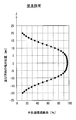
- FIG. 5 is a diagram illustrating the relationship between the disturbance magnetic field shielding rate and the position in the alignment direction in the first embodiment.
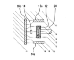
- FIG. 6 is a schematic diagram showing the direction of the magnetic field in the disturbance magnetic field applied in the alignment direction.
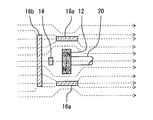
- FIG. 7 is a schematic diagram showing the direction of a magnetic field in a disturbance magnetic field including a component in the arrangement direction and a component orthogonal to the arrangement direction.
- FIG. 8 is a diagram illustrating a rotation angle detection device according to the second embodiment of the present disclosure.
- FIG. 9 is a diagram illustrating a rotation angle detection device according to the third embodiment of the present disclosure.
- FIG. 10 is a diagram illustrating a rotation angle detection device according to the fourth embodiment of the present disclosure.
- FIG. 11 is a diagram illustrating a current detection device according to the fifth embodiment of the present disclosure.
- FIG. 12 is a perspective view showing the shape of the first magnetic shield in another embodiment.
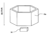
- FIG. 13 is a perspective view showing the shape of the first magnetic shield in another embodiment.
- FIG. 14 is a perspective view showing the shape of the first magnetic shield in another embodiment.
- an accelerator position detection device 100 including the rotation angle detection device 10 will be described as an example.
- the accelerator position detection device 100 detects the amount of depression of the accelerator pedal 200 of the automobile. That is, the rotation angle of the shaft 20 as the detected body that rotates as the accelerator pedal 200 is depressed is detected.
- the accelerator position detection device 100 is made of a rotation angle detection device 10 and an epoxy resin.
- An accelerator pedal 200 is disposed on the shaft 20 so that a moment of force is applied to the shaft 20 with the rotating shaft 22 as a fulcrum.
- the magnet 12 mentioned later is arrange
- the rotation angle detection device 10 includes a magnet 12 fixed to a shaft 20, a magnetoelectric conversion element 14 disposed opposite to the magnet 12, and a magnetic shield 16 that shields a disturbance magnetic field applied to the magnetoelectric conversion element 14. is doing.
- the magnet 12 for example, a disc-shaped magnet that is substantially orthogonal to the direction along the rotation axis 22 can be adopted.
- the magnet 12 in the present embodiment has magnetic poles in the radial direction (same as the direction substantially perpendicular to the direction along the rotation axis 22) and also has magnetic poles in the thickness direction (same as the direction along the rotation axis 22).
- This is a so-called double-sided quadrupole magnet. That is, the magnetic poles are provided in a direction substantially perpendicular to the rotation axis 22 of the shaft 20 and a direction along the rotation axis 22.
- a magnetic field formed by magnetic poles in a direction substantially perpendicular to the rotation axis 22 of the shaft 20 rotates as the shaft 20 rotates. The change in the magnetic field is detected by the magnetoelectric conversion element 14.
- the magnetoelectric conversion element 14 is mounted on the substrate 18 and arranged opposite to the magnet 12.
- the magnetoelectric conversion element 14 for example, a Hall element can be adopted.
- the magnets 12 and the magnetoelectric transducers 14 are arranged so as to have sensitivity in a direction substantially orthogonal to the direction in which the magnets 12 and the magnetoelectric conversion elements 14 are arranged (the same as the direction along the rotation axis 22, hereinafter simply referred to as the arrangement direction).
- the magnetic shield 16 is made of a magnetic material such as iron, and includes a first magnetic shield 16a and a second magnetic shield 16b.
- the first magnetic shield 16 a is arranged so as to surround a part of the facing region between the magnet 12 and the magnetoelectric conversion element 14 together with the magnet 12.
- the first magnetic shield 16 a has a bottomless cylindrical shape, and is arranged so that the central axis of the cylinder coincides with the rotation axis 22.
- the first magnetic shield 16 a is disposed on the magnet 12 side of the facing surface 14 a facing the magnet 12 in the magnetoelectric conversion element 14.
- the first magnetic shield 16a may be disposed so as to surround the entire facing region.
- the magnet 12 is not necessarily surrounded by the first magnetic shield 16a.
- the second magnetic shield 16b has the same radius as that of the first magnetic shield 16a, has a disk shape whose center axis also coincides with the first magnetic shield 16a, and is provided apart from the first magnetic shield 16a in the arrangement direction. ing. And the board
- the distance between the first magnetic shield 16a and the second magnetic shield 16b is equal to or greater than the total thickness of the substrate 18 and the magnetoelectric transducer 14 in the alignment direction. Yes.
- the inventor performed a simulation on the shielding effect of the disturbance magnetic field by the magnetic shield 16 using a computer.
- the inventor carried out a simulation assuming a cylindrical magnetic shield 16 as the magnetic shield 16 in the conventional configuration, and obtained the results shown in FIGS.
- This assumes a state in which the magnetic shield 16 is configured by only the first magnetic shield 16a in the present embodiment.
- the simulation conditions are as follows.
- the magnetic shield 16 made of iron and having a cylindrical shape with a thickness of 1 mm, a diameter of 18 mm, and a length of 20 mm has a disturbance magnetic field in a direction perpendicular to the axial direction (a direction from the right to the left in FIG. 2).
- the strength of the magnetic field in the state where the magnetic field was applied was simulated.
- the axial direction (alignment direction) of the cylinders is indicated as the Z direction
- the direction perpendicular to the Z direction is indicated as the X direction. That is, the disturbance magnetic field is applied in the X direction.
- the strength of the magnetic field is high near the outer periphery of the magnetic shield 16 and low in the internal space.
- the magnetoelectric conversion element 14 is arranged in the internal space of the magnetic shield 16 that is cylindrical, the structure, shape, wiring, etc. of the magnetoelectric conversion element 14 or the substrate 18 on which the magnetoelectric conversion element is arranged are arranged. There is a problem that the degree of freedom is limited by the magnetic shield 16.
- the disturbance magnetic field cannot be sufficiently shielded.
- the magnetic shield 16 has a second magnetic shield 16b in addition to the first magnetic shield 16a.
- the inventor performed simulation assuming the configuration of the magnetic shield 16 in the present embodiment, and obtained the results shown in FIGS. 4 and 5.
- the simulation conditions are as follows. A magnetic field is applied to the magnetic shield 16 in which both the first magnetic shield 16a and the second magnetic shield 16b are made of iron as a disturbance magnetic field in a direction perpendicular to the axial direction (a direction from the right to the left in FIG. 4).
- the strength of the magnetic field in the simulated state was simulated.
- the first magnetic shield 16a was cylindrical with a thickness of 1 mm, a diameter of 18 mm, and a length of 5 mm.
- the second magnetic shield was disk-shaped around the central axis of the first magnetic shield 16a, and had a diameter of 18 mm and a thickness (corresponding to the axial length of the first magnetic shield 16a) of 1 mm. And the 1st magnetic shield 16a and the 2nd magnetic shield 16b were arrange
- the axial direction of the cylinder (first magnetic shield 16a) is indicated as the Z direction
- the direction perpendicular to the Z direction is indicated as the X direction. That is, the disturbance magnetic field is applied in the X direction.
- the strength of the magnetic field is high on the outer periphery of the first magnetic shield 16a and the second magnetic shield 16b. Further, in the Z direction (that is, the arrangement direction), even in the range of ⁇ 5 mm ⁇ Z ⁇ 0 mm, which is the gap between the first magnetic shield 16 a and the second magnetic shield 16 b, the magnetic field in the portion corresponding to the outer periphery of the magnetic shield 16 Strength is high. On the other hand, in the range of ⁇ 5 mm ⁇ Z ⁇ 0 mm, the strength of the magnetic field is low in the vicinity of the central axes of the first magnetic shield 16a and the second magnetic shield 16b.
- the quantitative simulation results are shown in FIG. FIG.
- the magnetic shield 16 in this embodiment can shield a disturbance magnetic field by approximately 90% in a range of ⁇ 5 mm ⁇ Z ⁇ 0 mm. That is, it is possible to exhibit a shielding effect substantially equal to that of the center of gravity of the cylinder in the conventional configuration. In the present embodiment, the range of ⁇ 5 mm ⁇ Z ⁇ 0 mm is not surrounded by the magnetic shield 16.
- the magnetoelectric conversion element 14 and the substrate 18 are disposed in the region where the disturbance magnetic field can be shielded most without being limited by the degree of freedom of the structure of the substrate 18 on which the magnetoelectric conversion element 14 or the magnetoelectric conversion element 14 is disposed. Can do.
- the magnetoelectric conversion element 14 in order to facilitate the installation of the magnetoelectric conversion element 14, the magnetoelectric conversion element 14 is disposed in the vicinity of the opening of the cylindrical magnetic shield 16. As described above, in the vicinity of the opening of the magnetic shield 16, the disturbance magnetic field shielding rate is about 70%. Compared with this, in this embodiment, the disturbance magnetic field shielding rate is reduced at the position where the magnetoelectric transducer 14 is disposed. About 20 points can be improved.
- the configuration of the magnetic shield 16 in the present embodiment it is easy to arrange the magnetoelectric conversion element 14 while suppressing the disturbance magnetic field, and the degree of freedom of the structure of the magnetoelectric conversion element 14 or the substrate 18 is improved. Can be made.
- the magnetic shield 16 in the present embodiment includes a second magnetic shield 16b having a disk shape substantially orthogonal to the Z direction (alignment direction / axial direction of the cylinder).
- the second magnetic shield 16b functions as a magnetic path of a disturbance magnetic field in the vicinity of the opening end on the side where the magnetoelectric conversion element 14 is arranged in the first magnetic shield 16a.
- the components in the direction in which the magnet 12 and the magnetoelectric transducer 14 are arranged proceed in the above-described direction.
- the component orthogonal to the arrangement direction proceeds along the second magnetic shield 16b.
- the second magnetic shield 16b decomposes the invading magnetic field into an arrangement direction and a component orthogonal to the arrangement direction.
- the second magnetic shield 16b rectifies the magnetic field that has entered the second magnetic shield 16b in the alignment direction.
- the magnetoelectric conversion element 14 in this embodiment is arrange
- the magnetoelectric conversion element 14 is not easily affected by the disturbance magnetic field. Further, as shown in FIG. 7, even when a disturbance magnetic field enters from an arbitrary direction, the disturbance magnetic field is rectified by the second magnetic shield 16 b in the Z direction, which is the insensitive direction of the magnetoelectric transducer 14.
- the magnetoelectric conversion element 14 can be made less susceptible to the influence of the disturbance magnetic field.
- the substrate 18 and the package 300 are not shown in order to make it easier to see the direction of the magnetic field (lines of magnetic force).
- both the first magnetic shield 16a and the second magnetic shield 16b have a rotationally symmetric shape in which the central axis is the same as the rotational axis 22 of the shaft 20. Therefore, the direction dependency of the shielding effect in the direction substantially perpendicular to the rotating shaft 22 can be reduced.
- the first magnetic shield 16a is cylindrical
- the second magnetic shield 16b is disk-shaped. Therefore, a substantially uniform shielding effect can be exhibited in all directions substantially perpendicular to the rotating shaft 22.
- the dimensions of the magnetic shield 16 in the above simulation are merely examples, and are not limited to the above examples.
- the dimensions can be arbitrarily set according to the application, such as an accelerator position detection device that detects the accelerator opening, and a throttle position detection device that detects the throttle opening as in the present embodiment.
- the diameters of the first magnetic shield 16a and the second magnetic shield 16b can be set to, for example, 10 mm to 30 mm.
- the length of the first magnetic shield 16a can be 5 mm to 15 mm.
- the thicknesses of the magnetic bodies of the first magnetic shield 16a and the second magnetic shield 16b can be arbitrarily set, for example, 0.5 mm to 1 mm.
- the distance between the shields between the first magnetic shield 16a and the second magnetic shield 16b can also be set to 2 mm to 10 mm.
- FIG. 8 illustrates a main part of the rotation angle detection device 10, and a part of the accelerator pedal 200, the package 300, and the shaft 20 is omitted.
- the first feature of the present embodiment is that the magnetic shield 16 includes a third magnetic shield 16c in addition to the first magnetic shield 16a and the second magnetic shield 16b.
- the second feature is that the peripheral portion 16b2 surrounding the central portion 16b1 is made larger than the central portion 16b1 including the region overlapping the magnetoelectric transducer 14 with respect to the distance between the shields.
- the third magnetic shield 16c is arranged so as to cover the entire surface of the one surface 12a opposite to the second magnetic shield in the magnet 12 in the first embodiment. Yes.
- the third magnetic shield 16c is fixed to the one surface 12a of the magnet 12 via an adhesive (not shown).
- the constituent material of the third magnetic shield 16c can be, for example, an iron magnetic body, similarly to the first magnetic shield 16a and the second magnetic shield 16b.
- the third magnetic shield 16c can suppress the spread of the magnetic field formed on the side opposite to the magnetoelectric conversion element 14 with respect to the magnet 12 out of the magnetic field formed by the magnet 12. For this reason, it is possible to increase the strength of the magnetic field spreading toward the magnetoelectric conversion element 14 among the magnetic fields formed by the magnet 12. Thereby, the detection sensitivity of a rotation angle can be improved compared with the structure without the 3rd magnetic shield 16c. Moreover, the 3rd magnetic shield 16c can also show the effect which rectifies
- the example in which the third magnetic shield 16c is disposed so as to cover the entire surface of the one surface 12a opposite to the second magnetic shield in the magnet 12 is shown.
- the 3rd magnetic shield 16c is arrange
- by arranging the third magnetic shield 16c so as to cover the entire surface 12a the above-described effects can be more effectively exhibited.
- the second magnetic shield 16b is a flat plate
- the second magnetic shield 16b according to the present embodiment has the central portion 16b1 rather than the central portion 16b1 including a region where the second magnetic shield 16b overlaps the magnetoelectric transducer 14.
- the distance between the shields is reduced in the peripheral portion 16b2 that surrounds.
- the inside of the broken line in the second magnetic shield 16b shown in FIG. 8 is the center portion 16b1, and the distance between the shields in the center portion 16b1 is constant.
- the outer side of the broken line is the peripheral portion 16b2, and the peripheral portion 16b2 has a small distance between the shields in a partial range from the boundary with the central portion 16b1 toward the outer peripheral direction.
- the second magnetic shield 16b is shaped such that a part of the peripheral portion 16b2 gradually increases the distance between the shields toward the central portion 16b2, and faces the magnet 12 of the second magnetic shield 16b. It has a dish shape with a concave surface.
- the second magnetic shield 16b that may trap the magnetic field formed by the magnet 12 can be moved away from the vicinity of the magnetoelectric conversion element 14. For this reason, the magnetic field formed on the magnetoelectric conversion element 14 side by the magnet 12 can be made difficult to be trapped by the second magnetic shield 16b which is a magnetic body. Therefore, the detection sensitivity of the magnetic field formed by the magnet 12 by the magnetoelectric conversion element 14 can be improved.
- the shape of the second magnetic shield 16b is not limited to the dish shape as in the present embodiment.
- a concave portion is formed on the surface facing the magnet 12. May be provided.
- the substrate 18 can be, for example, a mold resin formed by molding a resin to protect the magnetoelectric conversion element 14. Further, the substrate 18 may be a printed circuit board, and may be a printed circuit board with a built-in electronic component including the magnetoelectric conversion element 14 such as PALAP (registered trademark). Also in the present embodiment, the second magnetic shield 16b is disposed with a predetermined inter-shield distance between the second magnetic shield 16b and the first magnetic shield 16a in the arrangement direction, as in the above-described embodiments. Specifically, the distance between the shields is the same as the thickness in the direction in which the substrates 18 are arranged.
- substrate 18 can be arrange
- the shaft 20 rotates about a rotation axis 24 in a direction substantially perpendicular to the arrangement direction of the magnet 12 and the magnetoelectric transducer 14, and the magnetic field around the magnet 12 rotating with the shaft 20 is changed. Change. This change in the magnetic field is detected by the magnetoelectric transducer 14.
- the configuration is the same as that of the first embodiment except for the arrangement direction and the rotation direction of the shaft 20 and the magnet 12. Therefore, the same effect as that of the first embodiment is achieved as an effect of shielding the disturbance magnetic field by the magnetic shield 16 and an effect of improving the degree of freedom of the structure of the substrate 18 on which the magnetoelectric conversion element 14 and the magnetoelectric conversion element 14 are arranged. be able to.
- the conducting wire 13 is electrically separated from the cylindrical first magnetic shield 16a, and the direction of current flow is substantially perpendicular to the central axis of the cylinder.
- the first magnetic shield 16a is disposed through.
- a current value can be detected by detecting this magnetic field by the magnetoelectric transducer 14. That is, the current detection device can be configured by using the configuration of the present embodiment.
- the second magnetic shield 16 b is disposed away from the first magnetic shield 16 a as in the above-described embodiments.
- the configuration of the magnetic shield 16, the magnetoelectric conversion element 14, and the magnetic field generation means in the present embodiment is the same as that of the first embodiment except that the magnet 12 is replaced with a conducting wire 13 as the magnetic field generation means.
- positioned. can play. Therefore, the current value of the current flowing through the conducting wire 13 can be detected while suppressing the influence of noise due to the disturbance magnetic field.
- the direction of the rotation axes 22 and 24 of the shaft 20 is a direction along the alignment direction of the magnet 12 and the magnetoelectric conversion element 14 or a substantially vertical direction.
- the direction of the rotation axis of the shaft is not limited to the above example.
- the rotating shafts 22 and 24 may be configured such that the magnetic field formed by the magnet 12 rotating with the rotation of the shaft 20 changes at the position where the magnetoelectric conversion element 14 is disposed.
- a double-sided quadrupole magnet is shown as an example of the magnet 12, but the magnet 12 is not limited to the above example.
- a bar magnet having magnetic poles at both ends may be used. In other words, it is only necessary that the magnetic field is changed at the position of the magnetoelectric conversion element 14 as the shaft 20 rotates.
- the first magnetic shield 16a In each of the above embodiments, an example in which a cylindrical magnetic body is used as the first magnetic shield 16a has been described. That is, the example in which the cross section perpendicular to the length direction of the first magnetic shield 16a is circular is shown. However, it is not limited to the above example.
- the 1st magnetic shield 16a should just be formed so that the opposing area
- the cross section may be C-shaped, or may be polygonal as shown in FIG. In FIG. 13, a regular hexagon is used as the cross section.
- the shielding effect of the disturbance magnetic field can be enhanced if the cross section is closed as shown in FIG.
- the cross section exhibits a rotationally symmetric shape, thereby reducing the azimuth dependence of the shielding effect of the disturbance magnetic field by the first magnetic shield 16a. Furthermore, since the cross section is a perfect circle as in each of the embodiments described above, the orientation dependency of the shielding effect can be eliminated.
- the first magnetic shield 16a may not have the same cross-sectional shape along the direction in which the magnet 12 and the magnetoelectric transducer 14 are arranged (that is, the length direction of the cylinder).
- the size of the openings of the first magnetic shields 16a in the arrangement direction may be different between the magnet 12 side and the magnetoelectric conversion element 14 side.
- the first magnetic shield 16a is on the magnet 12 side with respect to the facing surface 14a of the magnetoelectric conversion element 14 and the magnet 12 in the arrangement direction of the magnetoelectric conversion element 14 and the magnet 12, and magnetoelectric conversion is performed. It arrange
- the magnet 12 is composed of the magnetoelectric transducer 14 and the magnet.
- the first magnetic shield 16a may be disposed on the side where the magnetoelectric conversion element 14 is disposed.
Landscapes
- Physics & Mathematics (AREA)
- General Physics & Mathematics (AREA)
- Transmission And Conversion Of Sensor Element Output (AREA)
- Measurement Of Length, Angles, Or The Like Using Electric Or Magnetic Means (AREA)
Abstract
回転角検出装置において、磁気シールド(16)は、第1磁気シールド(16a)と第2磁気シールド(16b)とを有する。第1磁気シールド(16a)は、磁電変換素子(14)と磁石(12)の並び方向において、磁電変換素子(14)の磁石(12)との対向面よりも磁石(12)側、且つ、磁石(12)の少なくとも一部を囲むように配置されている。第2磁気シールド(16b)は、並び方向において、第1磁気シールド(16a)との間に、所定のシールド間距離を有して配置され、磁電変換素子(14)に対して、第1磁気シールド(16a)と反対側であって、磁石の回転により磁場が変化しない方向に、外乱磁場を整流するように配置される。
Description
本開示は、2012年3月29日に出願された日本出願番号2012-77237号および2013年2月28日に出願された日本出願番号2013-38365号に基づくもので、ここにその記載内容を援用する。
本開示は、磁電変換素子と磁石を用いて、被検出体の回転角を検出する回転角検出装置に関する。
自動車のアクセル開度やスロットル開度等、被検出体の回転角を検出する回転角検出装置が知られている。この回転角検出装置は、例えば、回転するシャフトの端部に取り付けられ、シャフトとともに回転する磁石の磁場を、磁電変換素子により検出し、シャフトの回転角を得るものである。このような回転角検出装置では、磁石による磁場ではない外乱磁場の影響により、検出精度が低下するおそれがある。
特許文献1では、磁電変換素子の周囲に、複数の磁石と、磁石と一体化され、磁石とともに筒状をなす磁性体(磁気シールド)と、を備えた回転角検出装置が提案されている。この磁気シールドは外乱磁場を遮蔽する機能を有する。
ところで、特許文献1に提案されたような筒状の磁気シールドでは、磁気シールドの重心付近で外乱磁場が最小となる。すなわち、外乱磁場の影響を低減する観点から、磁気シールドの重心近傍に磁電変換素子を配置することが望ましい。しかしながら、中空とされた磁気シールドの内部空間に磁電変換素子を配置すると、磁電変換素子もしくは磁電変換素子が配置される基板の体格、形状、配線など、構造の自由度が、磁気シールドにより制限される。
特許文献1では、この自由度の制限を緩和するために、筒の開口端近傍に磁電変換素子を配置している。しかしながら、筒の開口端近傍では、外乱磁場を十分に遮蔽できない。
本開示は、磁電変換素子と磁石と磁気シールドとを有する回転角検出装置において、外乱磁場の影響によるノイズを抑制しつつ、磁電変換素子もしくは磁電変換素子が配置される基板の構造の自由度を向上させることを目的とする。
本開示の一態様による回転角検出装置は、磁石と、磁電変換素子と、磁気シールドとを有する。前記磁石は、被検出体に取り付けられ、前記被検出体の回転にともなって回転する。前記磁電変換素子は、前記磁石の回転による磁場の変化を検出する。前記磁気シールドは、外乱磁場を遮断する。前記磁電変換素子と前記磁石とは、互いに離間しつつ対向配置される。前記磁気シールドは、第1磁気シールドと、第2磁気シールドとを有する。前記第1磁気シールドは、前記磁電変換素子と前記磁石の並び方向において、前記磁電変換素子の前記磁石との対向面よりも前記磁石側、且つ、前記磁石の少なくとも一部を囲むように配置される。前記第2磁気シールドは、前記並び方向において、前記第1磁気シールドとの間に、所定のシールド間距離を有するとともに、前記磁電変換素子に対して、前記第1磁気シールドと反対側であって、前記磁石の回転により磁場が変化しない方向に、外乱磁場を整流するように配置される。
前記回転角検出装置は、外乱磁場を抑制しつつ、磁電変換素子の配置が容易となり、磁電変換素子もしくは磁電変換素子が配置される基板の構造の自由度を向上させることができる。
本開示における上記あるいは他の目的、構成、利点は、下記の図面を参照しながら、以下の詳細説明から、より明白となる。図面において、
図1は、本開示の第1実施形態に係る回転角検出装置を含む、アクセル位置検出装置を示す図である。
図2は、従来構成における、外乱磁場の分布図である。
図3は、従来構成における、外乱磁場遮蔽率と並び方向の位置との関係を示す図である。
図4は、第1実施形態における、外乱磁場の分布図である。
図5は、第1実施形態における、外乱磁場遮蔽率と並び方向の位置との関係を示す図である。
図6は、並び方向に印加された外乱磁場中の、磁場の方向を示す概略図である
図7は、並び方向の成分と並び方向に直交する成分とを含む外乱磁場中の、磁場の方向を示す概略図である。
図8は、本開示の第2実施形態に係る回転角検出装置を示す図である。
図9は、本開示の第3実施形態に係る回転角検出装置を示す図である。
図10は、本開示の第4実施形態に係る回転角検出装置を示す図である。
図11は、本開示の第5実施形態に係る電流検出装置を示す図である。
図12は、別の実施形態における第1磁気シールドの形状を示す斜視図である。
図13は、別の実施形態における第1磁気シールドの形状を示す斜視図である。
図14は、別の実施形態における第1磁気シールドの形状を示す斜視図である。
以下、本開示の実施の形態を図面に基づいて説明する。なお、以下の各図相互において、互いに同一もしくは均等である部分に、同一符号を付与する。
(第1実施形態)
最初に、図1を参照して、本実施形態における回転角検出装置10の概略構成を説明する。
最初に、図1を参照して、本実施形態における回転角検出装置10の概略構成を説明する。
本実施形態では、その一例として、回転角検出装置10を備えたアクセル位置検出装置100について説明する。アクセル位置検出装置100は、自動車のアクセルペダル200の踏み込み量を検出する。すなわち、アクセルペダル200の踏み込みとともに回転する被検出体としてのシャフト20の回転角を検出する。
このアクセル位置検出装置100は、回転角検出装置10と、エポキシ樹脂等から成り、回転角検出装置10が収納されるパッケージ300と、アクセルペダル200が取り付けられ、回転角検出装置10と機械的に接続されたシャフト20と、を有している。シャフト20には、回転軸22を支点として、シャフト20に力のモーメントが印加されるようにアクセルペダル200が配置されている。そして、シャフト20の回転軸22に沿う方向の先端部に、後述する磁石12が配置され、アクセルペダル200の踏み込みとともに、磁石12が回転するようになっている。
回転角検出装置10は、シャフト20に固定された磁石12と、磁石12と対向配置された磁電変換素子14と、磁電変換素子14に印加される外乱磁場を遮蔽する磁気シールド16と、を有している。
磁石12は、例えば、回転軸22に沿う方向に略直交する円板形状の磁石を採用することができる。本実施形態における磁石12は、径方向(回転軸22に沿う方向に略直交する方向に同じ)に磁極を有するとともに、厚さ方向(回転軸22に沿う方向に同じ)にも磁極を有する、所謂、両面4極磁石である。すなわち、シャフト20の回転軸22に略垂直な方向および回転軸22に沿う方向に磁極を有している。シャフト20の回転軸22に略垂直な方向の磁極により形成される磁場が、シャフト20の回転に伴って回転する。そして、この磁場の変化が、磁電変換素子14により検出される。
磁電変換素子14は、基板18に実装され、磁石12と対向配置されている。磁電変換素子14としては、例えば、ホール素子を採用することができる。本実施形態では、磁石12と磁電変換素子14との並び方向(回転軸22に沿う方向に同じ。以下、単に並び方向と示す)に略直交する方向に感度を有するように配置されている。
磁気シールド16は、鉄などの磁性体から成り、第1磁気シールド16aと、第2磁気シールド16bとを有する。
本実施形態において、第1磁気シールド16aは、磁石12とともに、磁石12と磁電変換素子14との間の対向領域の一部を囲むように配置されている。具体的には、第1磁気シールド16aは、無底の円筒状とされ、円筒の中心軸が回転軸22と一致するように配置されている。また、第1磁気シールド16aは、磁電変換素子14における、磁石12と対向する対向面14aよりも磁石12側に配置されている。なお、第1磁気シールド16aは、上記した対向領域の全部を取り囲むように配置されてもよい。また、磁石12は、第1磁気シールド16aに必ずしも取り囲まれている必要はない。
第2磁気シールド16bは、第1磁気シールド16aと同一半径とされ、中心軸も第1磁気シールド16aと一致する円板状であり、並び方向において、第1磁気シールド16aと離間して設けられている。そして、第1磁気シールド16aと第2磁気シールド16bにより形成される隙間に、磁電変換素子14の実装された基板18、および、磁電変換素子14が配置される。換言すれば、第2磁気シールド16bは、並び方向において、磁電変換素子14に対して第1磁気シールド16aと反対側に配置されている。また、第2磁気シールド16bは、磁電変換素子14の、磁石12との対向面14aと反対の面14bと、全域に亘ってオーバーラップしている。本実施形態において、基板18は、第2磁気シールド16bと接して配置され、基板18のうち、第2磁気シールド16bと反対の面に磁電変換素子14が実装されている。
上記構成によれば、第1磁気シールド16aと第2磁気シールド16bの間のシールド間距離は、並び方向における、基板18の厚さと磁電変換素子14の厚さとを合わせた厚さ以上とされている。
次に、図2~図7を参照して、本実施形態に係る回転角検出装置10の作用効果を説明する。発明者は、磁気シールド16による外乱磁場の遮蔽効果について、コンピュータを用いてシミュレーションを実施した。
まず、従来構成におけるシミュレーション結果について説明する。発明者は、従来構成における磁気シールド16として、円筒状の磁気シールド16を想定してシミュレーションを実施し、図2および図3に示す結果を得た。これは、本実施形態における、第1磁気シールド16aのみで磁気シールド16が構成された状態を想定したものである。シミュレーションの条件は以下の通りである。鉄製であり、厚さ1mm、直径18mm、長さ20mmの円筒状とされた磁気シールド16に対し、外乱磁場として、軸方向に垂直な方向(図2において、紙面右から左に向かう方向)に磁場を印加した状態における磁場の強度をシミュレーションした。なお、図2および図3において、円筒の軸方向(並び方向)をZ方向と示し、Z方向に垂直な方向をX方向と示す。すなわち、外乱磁場はX方向に印加されている。また、Z方向は、円筒の長さ方向における中点をZ=0mmとした相対位置として示す。
図2に示すように、磁場の強度は、磁気シールド16の外周近傍で高く、内部空間で低い。とくに、磁気シールド16の内部空間において、磁気シールド16の軸上であって、Z=0mmとなる位置において、外乱磁場の強度が最小となる。定量的なシミュレーション結果を図3に示す。図3は、磁気シールド16の軸上における外乱磁場遮蔽率を、磁気シールド16の外部を0%として表している。図3に示すように、Z=0において、外乱磁場をほぼ100%遮蔽できている。したがって、図示しない磁石12の磁場の変化を検出するための磁電変換素子14は、磁気シールド16の軸上であって、Z=0mmとなる位置に配置されることが好ましい。すなわち、磁電変換素子14は磁気シールド16の重心部に配置されることが好ましい。しかしながら、上記のように、円筒とされた磁気シールド16の内部空間に磁電変換素子14を配置すると、磁電変換素子14もしくは磁電変換素子が配置される基板18の体格、形状、配線など、構造の自由度が、磁気シールド16により制限されるという問題がある。また、この自由度の制限を緩和するために、特許文献1のように、円筒の開口端近傍に磁電変換素子14を配置すると、外乱磁場を十分に遮蔽できないという問題がある。具体的には、図3に示すように、Z=0において、外乱磁場をほぼ100%遮蔽できているのに対して、磁気シールド16の開口であるZ=±10では、70%程度の遮蔽率にとどまっている。すなわち、外乱磁場を十分に遮蔽できない。
次いで、本実施形態の構成におけるシミュレーション結果について説明する。本実施形態では、磁気シールド16が、第1磁気シールド16aに加えて、第2磁気シールド16bを有している。発明者は、本実施形態における磁気シールド16の構成を想定してシミュレーションを実施し、図4および図5に示す結果を得た。シミュレーションの条件は以下の通りである。第1磁気シールド16aおよび第2磁気シールド16bがともに鉄製とされた磁気シールド16に対し、外乱磁場として、軸方向に垂直な方向(図4において、紙面右から左に向かう方向)に磁場を印加した状態における磁場の強度をシミュレーションした。第1磁気シールド16aを、厚さ1mm、直径18mm、長さ5mmの円筒状とした。また、第2磁気シールドを、第1磁気シールド16aの中心軸を中心とした円板状とし、直径18mm、厚さ(第1磁気シールド16aの軸方向の長さに相当)1mmとした。そして、第1磁気シールド16aと第2磁気シールド16bとを、並び方向において、5mmだけ離間して配置した。
なお、図4および図5において、円筒(第1磁気シールド16a)の軸方向をZ方向と示し、Z方向に垂直な方向をX方向と示す。すなわち、外乱磁場はX方向に印加されている。また、Z方向は、第1磁気シールド16aの長さ方向における、第2磁気シールド16bと対向する面をZ=0mmとした相対位置として示す。図4に示すように、Z=0mmの位置に対して、第2磁気シールド16bが配置される方向をZ方向における負方向としている。すなわち、第2磁気シールド16bにおける、第1磁気シールド16aと対向する面がZ=-5mmとなっている。
図4に示すように、第1磁気シールド16aと第2磁気シールド16bの外周において、磁場の強度が高くなっている。さらに、Z方向(すなわち、並び方向)において、第1磁気シールド16aと第2磁気シールド16bの隙間である-5mm<Z<0mmの範囲においても、磁気シールド16の外周に相当する部分で磁場の強度が高くなっている。これに対して、-5mm<Z<0mmの範囲において、第1磁気シールド16aおよび第2磁気シールド16bの中心軸近傍では、磁場の強度が低くなっている。定量的なシミュレーション結果を図5に示す。図5は、第1磁気シールド16aの軸上における外乱磁場遮蔽率を、磁気シールド16の外部を0%として表している。図5に示すように、本実施形態における磁気シールド16は、-5mm<Z<0mmの範囲において、外乱磁場を略90%遮蔽できている。すなわち、従来構成における円筒の重心部と、ほぼ同程度の遮蔽効果を発揮させることができる。そして、本実施形態では、-5mm<Z<0mmの範囲が磁気シールド16により囲まれていない。したがって、外乱磁場を最も遮蔽可能な領域に、磁電変換素子14もしくは磁電変換素子14が配置される基板18の構造の自由度に制限を受けることなく、磁電変換素子14および基板18を配置することができる。なお、特許文献1では、磁電変換素子14の設置を容易にするため、円筒状の磁気シールド16の開口近傍に、磁電変換素子14を配置している。上記したように、磁気シールド16の開口近傍では、外乱磁場遮蔽率は70%程度であり、これと比較すると、本実施形態において、磁電変換素子14が配置される位置では、外乱磁場遮蔽率を20ポイント程度向上させることができる。このように、本実施形態における磁気シールド16の構成を採用することにより、外乱磁場を抑制しつつ、磁電変換素子14の配置が容易となり、磁電変換素子14もしくは基板18の構造の自由度を向上させることができる。
また、本実施形態における磁気シールド16は、Z方向(並び方向/円筒の軸方向)と略直交する円板状とされた第2磁気シールド16bを有する。第2磁気シールド16bは、第1磁気シールド16aのうち、磁電変換素子14が配置される側の開口端近傍における外乱磁場の磁路として機能する。具体的には、図6および図7に示すように、第2磁気シールド16bに侵入した磁場のうち、磁石12と磁電変換素子14の並び方向の成分は前記方向に進む。また、並び方向に直交する成分は第2磁気シールド16bに沿って進む。すなわち、第2磁気シールド16bは、侵入した磁場を並び方向と並び方向に直交する成分とに分解する。換言すると、第2磁気シールド16bは、第2磁気シールド16bに侵入した磁場を並び方向に整流する。さらに、侵入磁場が整流されることにより、第2シールド16bから排出された磁場の、並び方向の成分の一部は、第1磁気シールド16aに導かれやすい状態になる。これにより、磁電変換素子14が配置される側の開口端近傍の磁場が小さくされる。なお、本実施形態における磁電変換素子14は、並び方向に略直交する方向に感度を有するように配置されている。このため、Z方向成分を含んだ外乱磁場が、磁電変換素子14の配置箇所に浸入した場合でも、磁電変換素子14が外乱磁場の影響を受けにくい。また、図7に示すように、任意の方向から外乱磁場が侵入した場合であっても、外乱磁場が第2磁気シールド16bによって、磁電変換素子14の不感方向であるZ方向に整流されるため、磁電変換素子14が外乱磁場の影響を受けにくくすることができる。
なお、図6および図7においては、磁場の方向(磁力線)を見やすくするため、基板18およびパッケージ300の図示を省略している。
また、本実施形態における磁気シールド16は、第1磁気シールド16aおよび第2磁気シールド16bが、ともに、シャフト20の回転軸22と中心軸を同一とする回転対称形状を呈している。したがって、回転軸22に略垂直な方向における遮蔽効果の方向依存性を低減することができる。とくに、本実施形態では、第1磁気シールド16aが円筒状であり、第2磁気シールド16bが円板状である。よって、回転軸22に略垂直な、あらゆる方向に対して、ほぼ均一な遮蔽効果を発揮することができる。
なお、上記したシミュレーションにおける磁気シールド16の寸法は一例であって、上記例に限定されるものではない。本実施形態のような、アクセルの開度を検出するアクセル位置検出装置や、スロットル開度を検出するスロットル位置検出装置など、用途に応じて寸法を任意に設定することができる。本実施形態のように、アクセル位置検出装置100に用いられる回転角検出装置10であれば、第1磁気シールド16aおよび第2磁気シールド16bの直径として、例えば、10mm~30mmとすることができる。また、第1磁気シールド16aの長さとして、5mm~15mmとすることができる。また、第1磁気シールド16aおよび第2磁気シールド16bの磁性体の厚さも任意に設定することができ、例えば、0.5mm~1mmとすることができる。また、第1磁気シールド16aと第2磁気シールド16bとの間のシールド間距離も、2mm~10mmとすることができる。
(第2実施形態)
図8を参照して、本実施形態における回転角検出装置10について説明する。本実施形態において、上記実施形態に示した回転角検出装置10と共通する部分についての説明は割愛する。また、図8は、回転角検出装置10の主要部分を図示しており、アクセルペダル200、パッケージ300、および、シャフト20の一部を省略している。
図8を参照して、本実施形態における回転角検出装置10について説明する。本実施形態において、上記実施形態に示した回転角検出装置10と共通する部分についての説明は割愛する。また、図8は、回転角検出装置10の主要部分を図示しており、アクセルペダル200、パッケージ300、および、シャフト20の一部を省略している。
本実施形態の第1の特徴は、磁気シールド16が、第1磁気シールド16aおよび第2磁気シールド16bに加えて、第3磁気シールド16cを有している点である。また、第2の特徴は、シールド間距離について、磁電変換素子14とオーバーラップする領域を含む中央部分16b1よりも、前記中央部分16b1を取り囲む周辺部分16b2が大きくされている点である。
まず、第1の特徴について説明する。図8に示すように、本実施形態では、第1実施形態に対して、磁石12における、第2磁気シールドと反対側の一面12aの全面を覆うように、第3磁気シールド16cが配置されている。本実施形態では、例えば、磁石12の一面12aに対し、図示しない接着剤を介して第3磁気シールド16cが固定されている。第3磁気シールド16cの構成材料は、例えば、第1磁気シールド16aおよび第2磁気シールド16bと同様に、鉄製の磁性体とすることができる。
この第3磁気シールド16cにより、磁石12が形成する磁場のうち、磁石12に対して磁電変換素子14と反対側への磁場の広がりを抑制することができる。このため、磁石12が形成する磁場のうち、磁電変換素子14側に広がる磁場の強度を大きくすることができる。これにより、第3磁気シールド16cの無い構成に較べて、回転角の検出感度を向上させることができる。また、第3磁気シールド16cは、第2磁気シールドと同様に、外乱磁場を磁石12と磁電変換素子14の並び方向(シャフト20の回転角22に沿う方向)に整流する効果も奏することができる。このため、磁電変換素子14が、外乱磁場によるノイズの影響を受けにくくすることができる。
なお、本実施形態では、第3磁気シールド16cが、磁石12における、第2磁気シールドと反対側の一面12aの全面を覆うように配置された例を示した。しかしながら、上記例に限定されるものではない。第3磁気シールド16cは、一面12aの少なくとも一部を覆うように配置されていれば、上記効果を奏することができる。すなわち、第3磁気シールド16cの一面12aと対向する面の面積は、一面12aよりも大きくてもよいし、小さくてもよい。ただし、第3磁気シールド16cが一面12aの全面を覆うように配置されることによって、より効果的に上記効果を発揮させることができる。
次いで、第2の特徴について説明する。第1実施形態では、第2磁気シールド16bが平板とされた例を示した。これに対して、本実施形態における第2磁気シールド16bは、図8に示すように、第2磁気シールド16bが磁電変換素子14とオーバーラップする領域を含む中央部分16b1よりも、前記中央部分16b1を取り囲む周辺部分16b2において、シールド間距離が小さくされている。具体的には、図8に示す第2磁気シールド16bのうち破線の内側が中央部分16b1であり、中央部分16b1におけるシールド間距離は一定とされている。そして、第2磁気シールド16bのうち破線の外側が周辺部分16b2であり、周辺部分16b2は、中央部分16b1との境界から外周方向に向かう一部の範囲で、シールド間距離が小さくされている。換言すれば、第2磁気シールド16bは、周辺部分16b2の一部が、中央部分16b2に向かって、次第にシールド間距離が大きくなるように成形され、第2磁気シールド16bの、磁石12と対向する面が凹んだ皿形状とされている。
これによれば、磁電変換素子14の近傍から、磁石12が形成する磁場をトラップする可能性のある第2磁気シールド16bの一部を、遠ざけることができる。このため、磁石12により磁電変換素子14側に形成される磁場が、磁性体である第2磁気シールド16bにトラップされにくくすることができる。したがって、磁石12が形成する磁場の、磁電変換素子14による検出感度を向上させることができる。
なお、第2磁気シールド16bの形状は、本実施形態のような皿形状に限定されるものではなく、例えば、平板状とされた第2磁気シールド16bのうち、磁石12と対向する面に凹部を設けてもよい。
(第3実施形態)
上記した各実施形態では、磁電変換素子14が基板18上に配置された例を示した。これに対して、本実施形態では、図9に示すように、磁電変換素子14が基板18内部に埋め込まれて配置される例を示す。本実施形態において、上記実施形態に示した回転角検出装置10と共通する部分についての説明は割愛する。
上記した各実施形態では、磁電変換素子14が基板18上に配置された例を示した。これに対して、本実施形態では、図9に示すように、磁電変換素子14が基板18内部に埋め込まれて配置される例を示す。本実施形態において、上記実施形態に示した回転角検出装置10と共通する部分についての説明は割愛する。
本実施形態において、基板18は、例えば、磁電変換素子14を保護するために樹脂を成形してなるモールド樹脂とすることができる。また、基板18は、プリント基板であってもよく、例えば、PALAP(登録商標)のように、磁電変換素子14を含む電子部品内蔵型のプリント基板とすることもできる。本実施形態でも、上記した各実施形態と同様に、第2磁気シールド16bが、並び方向において、第1磁気シールド16aとの間に、所定のシールド間距離を有して配置されている。具体的には、シールド間距離が、基板18の並び方向の厚さと同一とされている。このため、構造の自由度に制限を受けることなく、基板18を第1磁気シールド16aと第2磁気シールド16bとの隙間に配置することができる。したがって、外乱磁場を遮蔽しつつ、基板18の構造の自由度を向上させることができる。
(第4実施形態)
上記した各実施形態では、磁石12と磁電変換素子14の並び方向と、シャフト20の回転軸22が同一の方向を向いている例を示した。これに対して、本実施形態では、図10に示すように、回転軸24が並び方向と略垂直とされた例を示す。本実施形態において、上記実施形態に示した回転角検出装置10と共通する部分についての説明は割愛する。
上記した各実施形態では、磁石12と磁電変換素子14の並び方向と、シャフト20の回転軸22が同一の方向を向いている例を示した。これに対して、本実施形態では、図10に示すように、回転軸24が並び方向と略垂直とされた例を示す。本実施形態において、上記実施形態に示した回転角検出装置10と共通する部分についての説明は割愛する。
図10に示すように、本実施形態では、シャフト20が磁石12と磁電変換素子14の並び方向に略垂直な方向を回転軸24として回転し、シャフト20とともに回転する磁石12のまわりの磁場を変化させる。この磁場の変化が磁電変換素子14により検出される。
本実施形態では、シャフト20および磁石12の配置方向および回転方向を除いて、第1実施形態と同様の構成である。したがって、磁気シールド16による外乱磁場の遮蔽効果、および、磁電変換素子14と磁電変換素子14が配置される基板18の構造の自由度を向上させる効果として、第1実施形態と同様の効果を奏することができる。
(第5実施形態)
上記した各実施形態では、被検出体に取り付けられ、磁電変換素子14により検出する磁場を形成する磁場発生手段が磁石12である例を示した。しかしながら、磁場を形成する磁場発生手段として、電流が流れる導線を採用することもできる。なお、本実施形態において、上記実施形態に示した回転角検出装置10と共通する部分についての説明は割愛する。
上記した各実施形態では、被検出体に取り付けられ、磁電変換素子14により検出する磁場を形成する磁場発生手段が磁石12である例を示した。しかしながら、磁場を形成する磁場発生手段として、電流が流れる導線を採用することもできる。なお、本実施形態において、上記実施形態に示した回転角検出装置10と共通する部分についての説明は割愛する。
本実施形態では、図11に示すように、導線13が、円筒状とされた第1磁気シールド16aと電気的に分離されつつ、電流の流れる方向が円筒の中心軸と略垂直になるように、第1磁気シールド16aを貫通して配置されている。この導線13に電流が流れると、アンペールの法則に従って、導線13に垂直な方向に磁場が生じる。この磁場を磁電変換素子14により検出することで、電流値を検出することができる。すなわち、本実施形態の構成とすることにより、電流検出装置を構成することができる。なお、導線13と磁電変換素子14の並び方向において、第2磁気シールド16bは、上記した各実施形態と同様に、第1磁気シールド16aと離間して配置されている。
本実施形態における磁気シールド16、磁電変換素子14、および、磁場発生手段の構成は、磁場発生手段として、磁石12を導線13に置き換えたことを除き、第1実施形態と同様の構成である。このため、磁気シールド16による外乱磁場の遮蔽効果、および、磁電変換素子14と磁電変換素子14が配置される基板18の構造の自由度を向上させる効果として、第1実施形態と同様の効果を奏することができる。したがって、外乱磁場によるノイズの影響を抑制しつつ、導線13を流れる電流の電流値を検出することができる。
(その他の実施形態)
以上、本開示の好ましい実施形態について説明したが、本開示は上述した実施形態になんら制限されることなく、本開示の主旨を逸脱しない範囲において、種々変形して実施することが可能である。
以上、本開示の好ましい実施形態について説明したが、本開示は上述した実施形態になんら制限されることなく、本開示の主旨を逸脱しない範囲において、種々変形して実施することが可能である。
上記した各実施形態では、シャフト20の回転軸22,24の方向として、磁石12と磁電変換素子14の並び方向に沿う方向、あるいは略垂直な方向である例を示した。しかしながら、シャフトの回転軸の方向は、上記例に限定されるものではない。回転軸22,24は、シャフト20の回転とともに回転する磁石12が形成する磁場が、磁電変換素子14の配置される位置において変化するように構成されていればよい。
また、上記した各実施形態では、磁石12として、両面4極磁石を例に示したが、上記例に限定されるものではない。例えば、両端に磁極を有する棒磁石であってもよい。すなわち、シャフト20の回転に伴って、磁電変換素子14の位置において磁場が変化するように構成されていればよい。
また、上記した各実施形態では、第1磁気シールド16aとして、円筒状の磁性体が用いられる例を示した。すなわち、第1磁気シールド16aの長さ方向に垂直な断面が円形状となっている例を示した。しかしながら、上記例に限定されるものではない。第1磁気シールド16aは、磁石12と磁電変換素子14の対向領域を覆うように形成されていればよい。例えば、図12に示すように、上記断面がC字形状となっていてもよいし、図13に示すように多角形となっていてもよい。なお、図13では、上記断面として正六角形を採用している。ただし、上記断面が、図12に示すC字形状のような開いた構成に較べて、例えば、図11に示すように閉じた形状とされるほうが、外乱磁場の遮蔽効果を高めることができる。さらに言えば、図13に示すように、上記断面が回転対称形状を呈することにより、第1磁気シールド16aによる外乱磁場の、遮蔽効果の方位依存性を低減することができる。さらに、上記した各実施形態のように、上記断面が真円とされていることにより、遮蔽効果の方位依存性を無くすことができる。
また、第1磁気シールド16aは、上記断面の形状が、磁石12と磁電変換素子14の並び方向(すなわち、円筒の長さ方向)に沿って同一となっていなくともよい。例えば、図14に示すように、第1磁気シールド16aの、並び方向における開口の大きさが、磁石12側と磁電変換素子14側で互いに異なるようになっていてもよい。
また、上記した各実施形態では、第1磁気シールド16aが、磁電変換素子14と磁石12の並び方向において、磁電変換素子14の磁石12との対向面14aよりも磁石12側、且つ、磁電変換素子14と磁石12との対向領域の少なくとも一部を囲むように配置されている。すなわち、磁石12は、一部が第1磁気シールド16aに囲まれるか、あるいは、磁電変換素子14と磁石12の並び方向において、第1磁気シールド16aに対して、磁電変換素子14の反対側に配置されている。しかしながら、第1磁気シールド16aと第2磁気シールド16bの間のシールド間距離が、外乱磁場を遮蔽可能な距離であれば(シールド間距離が小さければ)、磁石12は、磁電変換素子14と磁石12の並び方向において、第1磁気シールド16aに対して、磁電変換素子14が配置された側に配置されていてもよい。
Claims (9)
- 被検出体に取り付けられ、前記被検出体の回転にともなって回転する磁石(12)と、
前記磁石(12)の回転による磁場の変化を検出する磁電変換素子(14)と、
外乱磁場を遮断する磁気シールド(16)と、を有する回転角検出装置であって、
前記磁電変換素子(14)と前記磁石(12)とは、互いに離間しつつ対向配置され、
前記磁気シールド(16)は、第1磁気シールド(16a)と、第2磁気シールド(16b)と、を有し、
前記第1磁気シールド(16a)は、前記磁電変換素子(14)と前記磁石(12)の並び方向において、前記磁電変換素子(14)の前記磁石(12)との対向面(14a)よりも前記磁石(12)側、且つ、前記磁石(12)の少なくとも一部を囲むように配置され、
前記第2磁気シールド(16b)は、前記並び方向において、前記第1磁気シールド(16a)との間に、所定のシールド間距離を有するとともに、前記磁電変換素子(14)に対して、前記第1磁気シールド(16a)と反対側であって、前記磁石(12)の回転により磁場が変化しない方向に、外乱磁場を整流するように配置されることを特徴とする回転角検出装置。 - 前記第1磁気シールド(16a)は、前記磁電変換素子(14)と前記磁石(12)との対向領域の少なくとも一部を囲むように配置され、
前記第2磁気シールド(16b)は、前記磁電変換素子(14)の前記対向面と反対の面(14b)の全域に亘ってオーバーラップするように配置されることを特徴とする請求項1に記載の回転角検出装置。 - 前記磁電変換素子(14)は、基板(18)に固定され、
前記シールド間距離が、前記基板(18)の前記並び方向の厚さ以上とされることを特徴とする請求項1または請求項2に記載の回転角検出装置。 - 前記第2磁気シールド(16b)は、前記磁電変換素子(14)とオーバーラップする領域を含む中央部分(16b1)における前記シールド間距離が、前記中央部分(16b1)を取り囲む周辺部分(16b2)における前記シールド間距離よりも、大きくされることを特徴とする請求項1~3のいずれか1項に記載の回転角検出装置。
- 前記第2磁気シールド(16b)の前記周辺部分(16b2)は、前記中央部分(16b1)との境界から外周方向に向けての少なくとも一部が、前記外周方向に向かうほど、前記シールド間距離が小さくされることを特徴とする請求項4に記載の回転角検出装置。
- 前記第1磁気シールド(16a)および第2磁気シールド(16b)は、中心軸を同一とする回転対称形状を呈することを特徴とする請求項1~5のいずれか1項に記載の回転角検出装置。
- 前記第1磁気シールド(16a)が円筒状であることを特徴とする請求項6に記載の回転角検出装置。
- 前記磁気シールド(16)は、前記磁石(12)における、前記第2磁気シールド(16b)と反対側の一面のうち、少なくとも一部を覆うように配置された第3磁気シールド(16c)を有することを特徴とする請求項1~7のいずれか1項に記載の回転角検出装置。
- 前記磁電変換素子(14)は、前記並び方向に直交する方向に感度を有することを特徴とする請求項1~8のいずれか1項に記載の回転角検出装置。
Priority Applications (1)
| Application Number | Priority Date | Filing Date | Title |
|---|---|---|---|
| DE201311001757 DE112013001757T5 (de) | 2012-03-29 | 2013-03-20 | Rotationswinkelerfassungsvorrichtung |
Applications Claiming Priority (4)
| Application Number | Priority Date | Filing Date | Title |
|---|---|---|---|
| JP2012077237 | 2012-03-29 | ||
| JP2012-077237 | 2012-03-29 | ||
| JP2013038365A JP6134941B2 (ja) | 2012-03-29 | 2013-02-28 | 回転角検出装置 |
| JP2013-038365 | 2013-02-28 |
Publications (1)
| Publication Number | Publication Date |
|---|---|
| WO2013145644A1 true WO2013145644A1 (ja) | 2013-10-03 |
Family
ID=49258957
Family Applications (1)
| Application Number | Title | Priority Date | Filing Date |
|---|---|---|---|
| PCT/JP2013/001889 Ceased WO2013145644A1 (ja) | 2012-03-29 | 2013-03-20 | 回転角検出装置 |
Country Status (3)
| Country | Link |
|---|---|
| JP (1) | JP6134941B2 (ja) |
| DE (1) | DE112013001757T5 (ja) |
| WO (1) | WO2013145644A1 (ja) |
Cited By (3)
| Publication number | Priority date | Publication date | Assignee | Title |
|---|---|---|---|---|
| WO2020121566A1 (ja) * | 2018-12-14 | 2020-06-18 | パナソニックIpマネジメント株式会社 | 磁気センサユニット |
| US11046423B2 (en) | 2019-07-18 | 2021-06-29 | Pratt & Whitney Canada Corp. | Blade angle position feedback system with magnetic shield |
| US12613109B2 (en) * | 2021-03-24 | 2026-04-28 | Tdk Corporation | Angle detection apparatus, angle detection system, park lock system, and pedal system |
Families Citing this family (5)
| Publication number | Priority date | Publication date | Assignee | Title |
|---|---|---|---|---|
| JP6123687B2 (ja) * | 2014-01-29 | 2017-05-10 | 株式会社デンソー | 磁気センサ |
| EP3516759B1 (en) * | 2016-09-23 | 2022-11-16 | Suzhou Littelfuse OVS Co., Ltd. | Rotary position sensor with dual magnet arrangement |
| DE102017106479A1 (de) * | 2017-03-27 | 2018-09-27 | Fritz Kübler GmbH | Abschirmsystem für magnetisches Drehgeber-Sensorsystem |
| JP6778168B2 (ja) * | 2017-09-13 | 2020-10-28 | 株式会社東海理化電機製作所 | シフト装置 |
| JP2023109265A (ja) * | 2022-01-27 | 2023-08-08 | 三菱電機株式会社 | 回転角度検出装置及びそれを用いた回転電機 |
Citations (3)
| Publication number | Priority date | Publication date | Assignee | Title |
|---|---|---|---|---|
| JP2001004405A (ja) * | 1999-06-22 | 2001-01-12 | Sankyo Seiki Mfg Co Ltd | 磁気式エンコーダ装置 |
| JP2010139351A (ja) * | 2008-12-11 | 2010-06-24 | Tokyo Cosmos Electric Co Ltd | 回転角度センサ |
| JP2010169652A (ja) * | 2008-12-26 | 2010-08-05 | Nippon Seiki Co Ltd | 回転角度検出装置 |
Family Cites Families (4)
| Publication number | Priority date | Publication date | Assignee | Title |
|---|---|---|---|---|
| US5444369A (en) * | 1993-02-18 | 1995-08-22 | Kearney-National, Inc. | Magnetic rotational position sensor with improved output linearity |
| JPH0849575A (ja) * | 1994-08-08 | 1996-02-20 | Nippondenso Co Ltd | アクセルペダルの操作量検出装置 |
| JP2000074613A (ja) * | 1998-08-31 | 2000-03-14 | Toyota Motor Corp | 回転角度センサ |
| JP2004257894A (ja) * | 2003-02-26 | 2004-09-16 | Hitachi Unisia Automotive Ltd | 回動角検出装置 |
-
2013
- 2013-02-28 JP JP2013038365A patent/JP6134941B2/ja not_active Expired - Fee Related
- 2013-03-20 DE DE201311001757 patent/DE112013001757T5/de not_active Withdrawn
- 2013-03-20 WO PCT/JP2013/001889 patent/WO2013145644A1/ja not_active Ceased
Patent Citations (3)
| Publication number | Priority date | Publication date | Assignee | Title |
|---|---|---|---|---|
| JP2001004405A (ja) * | 1999-06-22 | 2001-01-12 | Sankyo Seiki Mfg Co Ltd | 磁気式エンコーダ装置 |
| JP2010139351A (ja) * | 2008-12-11 | 2010-06-24 | Tokyo Cosmos Electric Co Ltd | 回転角度センサ |
| JP2010169652A (ja) * | 2008-12-26 | 2010-08-05 | Nippon Seiki Co Ltd | 回転角度検出装置 |
Cited By (9)
| Publication number | Priority date | Publication date | Assignee | Title |
|---|---|---|---|---|
| WO2020121566A1 (ja) * | 2018-12-14 | 2020-06-18 | パナソニックIpマネジメント株式会社 | 磁気センサユニット |
| CN113167601A (zh) * | 2018-12-14 | 2021-07-23 | 松下知识产权经营株式会社 | 磁传感器单元 |
| JPWO2020121566A1 (ja) * | 2018-12-14 | 2021-10-21 | パナソニックIpマネジメント株式会社 | 磁気センサユニット |
| JP7462133B2 (ja) | 2018-12-14 | 2024-04-05 | パナソニックIpマネジメント株式会社 | 磁気センサユニット |
| US11982525B2 (en) | 2018-12-14 | 2024-05-14 | Panasonic Intellectual Property Management Co., Ltd. | Magnetic sensor unit |
| CN113167601B (zh) * | 2018-12-14 | 2024-12-17 | 松下知识产权经营株式会社 | 磁传感器单元 |
| US11046423B2 (en) | 2019-07-18 | 2021-06-29 | Pratt & Whitney Canada Corp. | Blade angle position feedback system with magnetic shield |
| US11623735B2 (en) | 2019-07-18 | 2023-04-11 | Pratt & Whitney Canada Corp. | Blade angle position feedback system with magnetic shield |
| US12613109B2 (en) * | 2021-03-24 | 2026-04-28 | Tdk Corporation | Angle detection apparatus, angle detection system, park lock system, and pedal system |
Also Published As
| Publication number | Publication date |
|---|---|
| JP2013228371A (ja) | 2013-11-07 |
| DE112013001757T5 (de) | 2015-02-26 |
| JP6134941B2 (ja) | 2017-05-31 |
Similar Documents
| Publication | Publication Date | Title |
|---|---|---|
| JP6134941B2 (ja) | 回転角検出装置 | |
| JP5231365B2 (ja) | 回転角度検出センサ | |
| CN104897182B (zh) | 磁检测型编码器用磁屏蔽罩和磁检测型编码器 | |
| JP7270614B2 (ja) | モータビークルの回転ハンドルを検出するためのモジュール | |
| TWI691701B (zh) | 編碼器 | |
| JP2009229395A (ja) | 回転センサユニット | |
| JP2006340936A5 (ja) | ||
| US8575926B2 (en) | Planar magnetic field probe | |
| CN113167665B (zh) | 扭矩传感器装置和机电转向系统 | |
| US9817095B2 (en) | Method for electromagnetic shielding for a magnetic resonance system and correspondingly shielded device | |
| JP6430043B2 (ja) | 回転角検出装置および電動機 | |
| JP4640708B2 (ja) | 回転角度検出装置 | |
| US7339371B2 (en) | Rotation angle detector | |
| JP6032534B2 (ja) | 磁気シールド及びこれを備えた電流検出器 | |
| JP5082473B2 (ja) | ロータリエンコーダ | |
| MX2007011998A (es) | Ensamble de sensor. | |
| US7355390B2 (en) | Rotation angle sensor | |
| JP2021076468A (ja) | 電流センサ | |
| JP2010169652A (ja) | 回転角度検出装置 | |
| JP2020145121A (ja) | 近接センサユニット | |
| JP2013029437A (ja) | 表面電流プローブ | |
| US20140333297A1 (en) | Rotary position detection device | |
| JP2024150241A (ja) | 回転速センサ | |
| JP2021124460A (ja) | 回転検出装置 | |
| JP2021006775A (ja) | 回転角度検出装置 |
Legal Events
| Date | Code | Title | Description |
|---|---|---|---|
| 121 | Ep: the epo has been informed by wipo that ep was designated in this application |
Ref document number: 13768734 Country of ref document: EP Kind code of ref document: A1 |
|
| WWE | Wipo information: entry into national phase |
Ref document number: 1120130017571 Country of ref document: DE Ref document number: 112013001757 Country of ref document: DE |
|
| 122 | Ep: pct application non-entry in european phase |
Ref document number: 13768734 Country of ref document: EP Kind code of ref document: A1 |