WO2013145542A1 - 電子体温計及びその制御方法 - Google Patents
電子体温計及びその制御方法 Download PDFInfo
- Publication number
- WO2013145542A1 WO2013145542A1 PCT/JP2013/001057 JP2013001057W WO2013145542A1 WO 2013145542 A1 WO2013145542 A1 WO 2013145542A1 JP 2013001057 W JP2013001057 W JP 2013001057W WO 2013145542 A1 WO2013145542 A1 WO 2013145542A1
- Authority
- WO
- WIPO (PCT)
- Prior art keywords
- electronic thermometer
- mode
- temperature measurement
- body temperature
- current consumption
- Prior art date
Links
Images


Classifications
-
- G—PHYSICS
- G01—MEASURING; TESTING
- G01K—MEASURING TEMPERATURE; MEASURING QUANTITY OF HEAT; THERMALLY-SENSITIVE ELEMENTS NOT OTHERWISE PROVIDED FOR
- G01K13/00—Thermometers specially adapted for specific purposes
- G01K13/20—Clinical contact thermometers for use with humans or animals
-
- G—PHYSICS
- G01—MEASURING; TESTING
- G01K—MEASURING TEMPERATURE; MEASURING QUANTITY OF HEAT; THERMALLY-SENSITIVE ELEMENTS NOT OTHERWISE PROVIDED FOR
- G01K2215/00—Details concerning sensor power supply
Definitions
- the present invention relates to an electronic thermometer.
- thermometers may be disinfected by immersing them in chemicals to prevent infection. Therefore, the thermometer is sealed so that the chemical solution does not enter the thermometer. Then, using a magnet reed switch, the power is turned on and off by putting the thermometer in and out of the storage case.
- the thermometer since the thermometer is formed of a sealed casing, it has a specification that the battery cannot be replaced.
- thermometer is left out of the storage case, the battery is depleted because it is always energized.
- thermometer the power is turned off after a certain period of time, or a switch is attached to the external housing part of the thermometer to make a transition to low current consumption.
- Patent Document 1 discloses a configuration in which, when the temperature is low, it is determined that there is time until the next temperature detection, and the current consumption is reduced by dropping the clock.
- the temperature measurement result is not known.
- it is also possible to store the temperature measurement result as the previous value but if the specification is to display the previous value for a long time at the next measurement, there is a possibility of being confused with the next temperature measurement result, There are inconveniences such as being unable to display a display outside the measurement environment range. For this reason, at present, the specification is such that the display cannot be performed for a long time (the display is switched to the next display in a few seconds), and therefore the accurate temperature measurement result cannot be transferred or grasped. Furthermore, in order to attach a switch to the external casing portion of the thermometer, a mechanism for maintaining liquid tightness is required, which is a costly factor.
- thermometers for hospitals assume that the temperature measurement starts immediately after being taken out of the storage case, so immediately after being taken out of the storage case, the sampling state at the time of temperature measurement (measurement mode) It has become. That is, the hospital thermometer is not devised to reduce the current consumption during the time period until the thermometer is started or until the thermometer is stored in the storage case after the end of the temperature measurement.
- thermometer is turned on with low power enough to maintain the temperature measurement result even after the time period until auto power off works.
- the present invention has been made in view of the above problems, and by performing more appropriate power control according to the usage state of the electronic thermometer, an electronic thermometer that can improve the battery life without cost, and An object is to provide a control method thereof.
- an electronic thermometer has the following configuration. That is, An electronic thermometer, Detecting means for detecting a temperature change of the electronic thermometer; Determining whether or not the electronic thermometer in which the power is already turned on and in the body temperature measurement mode is in a state where body temperature measurement should be performed in the body temperature measurement mode based on the temperature change detected by the detection means Means, As a result of the determination by the determination means, when it is determined that the electronic thermometer is not in a state where the body temperature measurement mode should not be measured, the body temperature measurement mode is operated at a power lower than the power consumption in the body temperature measurement mode. And a transition means for transitioning to the low current consumption mode.
- thermometer that can improve battery life and a control method thereof without increasing costs by performing more appropriate power control according to the use state of the electronic thermometer.
- thermometer It is a flowchart which shows the electric power control process of an electronic thermometer. It is a figure which shows the mode of the temperature change accompanying a series of usage condition (time passage) of an electronic thermometer. It is a figure which shows the example of a display of the display part at the time of low power consumption mode.
- FIG. 1 is a diagram showing the external appearance of an electronic thermometer and its storage case according to this embodiment.
- the storage case 120 has the storage part 122 which is a container main body, and the cover part 121 as a cap member.
- the storage case 120 is made of plastic.
- the lid 121 is attached to the storage unit 122 via the rotation unit 15 and is rotated by the rotation unit 15 to allow the storage case 120 to be opened and closed. If the lid 121 is formed of, for example, a transparent member, it can be immediately recognized whether or not the electronic thermometer 100 (1b in FIG. 1) is stored in the storage case 120.
- a window 13 is provided on the top panel of the storage unit 122. The user can view the display unit 104 of the electronic thermometer 100 stored in the internal space of the storage case 120 from the outside. The user can know whether or not the electronic thermometer 100 is stored in the storage case 120 through the window 13. However, when the lid 121 is made transparent as described above, the window 13 can be omitted.
- the opening 14 for inserting and removing the electronic thermometer 100 is exposed to the internal space of the storage unit 122.
- the electronic thermometer 100 is stored in the storage case 120, the electronic thermometer 100 is inserted into the internal space of the storage unit 122 from the end cap 103 side.
- the storage unit 122 is obtained by integrally molding an upper panel, a lower panel, and a side panel by injection molding.
- the storage portion 122 is formed of an impact-resistant thermoplastic resin, for example, a styrene resin such as a high impact styrene resin or an ABS resin.
- the storage case 120 becomes a structure which accommodates the one electronic thermometer 100, it is not limited to this.
- a storage case that can store a plurality (units of 2, 4, 6, 8, 10, etc.) of electronic thermometers 100 may be used.
- 1c in FIG. 1 shows an example of a storage case that can store ten electronic thermometers 100 in a two-row configuration, with five in each row.
- FIG. 1b shows an external perspective view of the electronic thermometer 100 according to the present embodiment, together with a conceptual diagram for inserting the electronic thermometer 100 into the storage section 122.
- reference numeral 101 denotes a main body housing (housing 101) of the electronic thermometer 100.
- the casing 101 is made of an impact-resistant thermoplastic resin, such as a high-impact styrene resin or ABS resin.
- Reference numeral 103 denotes an end cap.
- the end cap 103 is covered with a metal such as stainless steel so that the body temperature of the subject can be easily conducted to the built-in temperature measurement unit.
- a temperature measuring unit such as a thermistor for measuring temperature is housed in the end cap 103 and has liquid tightness.
- a display unit 104 displays data such as body temperature data as a body temperature measurement result, and is covered with a window member 104a formed of a transparent thermoplastic resin.
- the window member 104a is two-color molded with the housing 101 and has high liquid tightness.
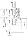
- FIG. 2 is an internal block diagram showing a functional configuration of the electronic thermometer 100 of the present embodiment.
- the electronic thermometer 100 has, as its operation mode, power consumption in a period when it is determined that the electronic thermometer 100 is left in addition to a normal body temperature measurement mode for measuring the body temperature of the subject. It has a low current consumption mode to reduce.
- This low current consumption mode is a mode in which operation is performed with lower power than that in the body temperature measurement mode.
- the electronic thermometer 100 calculates a body temperature of the subject by performing various processes based on the temperature measurement unit 210 that outputs an ON signal for a time corresponding to the temperature, and the ON signal output from the temperature measurement unit 210. And an arithmetic control unit 220 that controls the operation of the entire electronic thermometer 100. Further, the electronic thermometer 100 includes a display unit 104 that displays the calculated body temperature of the subject, an audio output unit 240 that outputs audio data, a power supply unit 250, and a sensor unit 260.
- the display part 104 is comprised by the liquid crystal display part for displaying measurement information, such as body temperature, for example.
- the display unit 104 can display status information of the electronic thermometer 100 (for example, a low current consumption mode, a body temperature measurement mode, etc.).
- the temperature measurement unit 210 includes a thermistor (measurement resistance element) and a reference resistance element, which are arranged in the end cap 103 and connected in parallel to each other, and a single input integration type A / D conversion circuit. Then, the temperature measurement unit 210 outputs an ON signal corresponding to the temperature (a digital signal that changes the ON time corresponding to the temperature).
- the integration method is adopted as the temperature measurement method of the temperature measurement unit 210.
- the present invention is not limited to this, and other methods such as a CR oscillation method using a CR oscillation circuit are used. It may be used.
- the arithmetic control unit 220 includes a timer 222 that measures the ON time of the digital signal output from the temperature measurement unit 210.
- the timer 222 can also measure the time since the power supply unit 250 is turned on.
- the arithmetic control unit 220 can control ON / OFF and reset of the timer 222 according to a predetermined condition. Therefore, the arithmetic control unit 220 can switch between the body temperature measurement mode and the low current consumption mode based on the measurement time of the timer 222 as a predetermined condition.
- the arithmetic control unit 220 includes a ROM 224, an EEPROM 225, and a RAM 226.
- the ROM 224 stores a program for calculating temperature data based on the time measured by the timer 222 and predicting and calculating the body temperature of the subject based on the time change of the calculated temperature data.
- the RAM 226 stores the calculated temperature data in time series.
- the EEPROM 225 stores predetermined audio data, calibration values, sample numbers, error information, the number of measurements, and the like.
- the arithmetic control unit 220 performs arithmetic operations according to programs stored in the ROM 224 and outputs audio data, and a display for controlling the display unit 104 that displays arithmetic results in the arithmetic processing unit 223.
- a control unit 227 is provided.
- the calculation control unit 220 includes a control circuit 221 that controls the timer 222, the display control unit 227, the calculation processing unit 223, the temperature measurement unit 210, and the sensor unit 260.
- the sensor unit 260 is a sensor for detecting the state of the electronic thermometer 100.
- This sensor includes a temperature sensor that detects the environmental temperature of the electronic thermometer 100, an acceleration sensor that detects a physical external force (tilt and vibration) acting on the electronic thermometer 100, a tilt / vibration switch, and an object to the electronic thermometer 100.
- thermometer 100 it is also possible to detect the environmental temperature of the electronic thermometer 100 by the temperature measurement unit 210 instead of mounting a temperature sensor on the sensor unit 260.
- the electronic thermometer 100 is provided with a magnet reed switch (not shown). For this reason, when the electronic thermometer 100 is taken out of the storage case 120, the magnet reed switch is turned on, and power is continuously supplied from the power supply unit 250 to various components such as the arithmetic control unit 220, the temperature measurement unit 210, and the display unit 104. It will be. And if the electronic thermometer 100 is accommodated in the storage case 120 containing a permanent magnet, supply of a power supply will be interrupted
- Body temperature measurement processing with electronic thermometer> First, the body temperature measurement process in the electronic thermometer executed in the body temperature measurement mode will be described.
- the temperature measurement process of the electronic thermometer 100 of the equilibrium temperature prediction type will be described, the present invention is not limited to this, and can be applied to an actual measurement type electronic thermometer and a prediction / measurement type electronic thermometer. .
- the electronic thermometer 100 When the electronic thermometer 100 is attached to the measurement site of the subject, the electronic thermometer 100 starts temperature measurement at a predetermined cycle (sampling rate), and the subject is based on the time change of the acquired temperature data. The body temperature is predicted.
- a predetermined cycle sampling rate
- FIG. 3 is a flowchart showing body temperature measurement processing in the electronic thermometer 100.
- the electronic thermometer 100 When the power supply unit 250 of the electronic thermometer 100 is turned on, the electronic thermometer 100 is initialized in step S301, and temperature measurement by the thermistor is started. For example, the arithmetic processing unit 223 calculates temperature data as a sampling rate for measuring body temperature at a predetermined interval, for example, every 0.5 seconds.
- step S302 it is determined whether or not a body temperature measurement start condition is satisfied. Specifically, whether or not the degree of increase from the value of the temperature data calculated by the previous temperature measurement (that is, the value of the temperature data 0.5 seconds before) has become a predetermined value (for example, 1 ° C.) or more. Determine whether.
- the degree of increase is equal to or greater than a predetermined value
- step S302 If it is determined in step S302 that the body temperature measurement start condition is satisfied (YES in step S302), the process proceeds to step S303, and temperature data acquisition is started. Specifically, the output temperature data and the timing at which the temperature data is measured are stored in the RAM 226 as time series data. On the other hand, if it is determined that the body temperature measurement start condition is not satisfied (NO in step S302), the process waits until it is determined that the body temperature measurement start condition is satisfied. Alternatively, when a predetermined time or more has elapsed, a low-consumption current mode described later may be entered as a measurement error.
- step S304 the predicted body temperature is calculated by a predetermined prediction formula using the temperature data stored in the RAM 226 in step S303.
- step S305 If it is determined in step S305 that the prediction establishment condition is satisfied (YES in step S305), the process proceeds to step S306, and the temperature measurement is terminated.
- step S307 a sound indicating that the calculation of the predicted body temperature has been completed is output, and the calculated predicted body temperature is displayed on the display unit 104 as the body temperature of the measured value.
- step S305 when it is determined in step S305 that the prediction establishment condition is not satisfied (NO in step S305), the process proceeds to step S309.
- a predetermined time for example, 45 seconds
- the magnet reed switch of the electronic thermometer 100 is turned off and the power supply from the power supply unit 250 is turned on. It is turned off.
- FIG. 4 is a diagram illustrating a detailed configuration of the temperature measurement unit 210.
- the thermistor 401 and the reference resistance element 402 are each connected to a capacitor 403.
- the capacitor 403 is charged to the voltage V from the voltage switching unit 410 via the thermistor 401 or the reference resistance element 402, but may be charged via a charging resistance element (not shown).
- the electric charge charged in the capacitor 403 is caused by dropping the voltage switching unit 410 connected to the thermistor 401 to the GND level, or dropping the voltage switching unit 410 connected to the reference resistance element 402 to the GND level. , And are discharged through the thermistor 401 and the reference resistance element 402, respectively. In discharging, the output of the voltage switching unit 410 that is not used for discharging is switched to high impedance.
- the reference resistance element 402 is a resistance element having a constant resistance value regardless of variations in ambient temperature. For this reason, when the voltage V is constant, the discharge time when discharged through the reference resistance element 402 is constant.
- the thermistor 401 is a resistance element whose resistance value fluctuates according to fluctuations in ambient temperature. For this reason, the discharge time when discharged via the thermistor 401 varies according to the ambient temperature.
- the discharge time is always constant when the voltage V is discharged through the reference resistance element 402, and when the voltage V is discharged through the thermistor 401, the discharge time is It depends on the temperature.
- the amount of charge accumulated in the capacitor 403 is detected via the A / D conversion unit 420.
- the comparator 421 that constitutes the A / D conversion unit 420 is used while the capacitor 403 has a voltage equal to or higher than a voltage (here, 0.25 V) of a predetermined ratio of the voltage V applied via the voltage switching unit 410. , A predetermined signal is output. As a result, the A / D converter 420 outputs an ON signal as a digital signal.
- the capacitor 403 and the A / D conversion unit 420 form a single input integration type A / D conversion circuit.
- the voltage across the capacitor 403 gradually decreases.
- the digital signal output from the A / D converter 420 becomes an OFF signal.
- the timer 222 measures the ON time (discharge time) of the digital signal output from the A / D converter 420.
- the discharge time is constant when discharged through the reference resistance element 402.
- the resistance value fluctuates according to the ambient temperature, so the discharge time also fluctuates.
- the electronic thermometer 100 measures the discharge time when the charge accumulated in the capacitor 403 is discharged through the thermistor 401 in a state where the ambient temperature is known (reference temperature). In addition, the electronic thermometer 100 measures the discharge time when the charge accumulated in the capacitor 403 is discharged through the reference resistance element 402.
- a standardized discharge time T at the measured temperature is calculated based on the following equation.
- a table representing the correspondence relationship between the discharge time and the temperature is recorded, and the normalized discharge time T is converted into temperature by comparing with the table.
- T T37 ⁇ (Tth / Tref) ⁇ (Tref37 / Tth37)
- the reference temperature is 37 ° C.
- Tref37 indicates a discharge time measured when discharging is performed through the reference resistance element 402 at the reference temperature.
- Tth37 indicates a discharge time measured when discharging is performed via the thermistor 401 at the reference temperature.
- Tref indicates a discharge time measured when discharging is performed through the reference resistance element 402 in the temperature measurement process.
- Tth indicates a discharge time measured when discharging is performed through the thermistor 401 in the temperature measurement process.
- T37 indicates a discharge time obtained when a resistance value serving as a reference for normalization is used at the reference temperature.
- FIG. 5 is a flowchart showing details of the temperature measurement process.
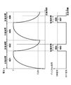
- FIG. 6 is a diagram showing the time change of the voltage across the capacitor 403 and the time change of the digital signal output from the A / D converter 420. A general temperature measurement process will be described with reference to FIGS. 5 and 6.
- step S501 the capacitor 403 is charged.
- Reference numeral 601 in FIG. 6 indicates a period (charge period) in which charges are gradually accumulated in the capacitor 403.
- step S502 discharge period 602
- the timer 222 measures the time of the ON signal.
- the time (discharge time 604) Tref from when the discharge is started until the voltage of the capacitor 403 becomes equal to or lower than a predetermined voltage (here, 0.25 V) is measured (see 602 in FIG. 6).
- Reference numeral 605 in FIG. 6 indicates a period (charge period) in which charges are gradually accumulated in the capacitor 403.
- the capacitor 403 is discharged in step S504 (discharge period 606).
- the timer 222 measures the time of the ON signal.
- Tth the time (discharge time 608) Tth from the start of discharge until the voltage of the capacitor 403 becomes equal to or lower than a predetermined voltage (here, 0.25 V) is measured. Tth varies depending on the ambient temperature of the thermistor 401.
- the fluctuation ratio is obtained and the standardized discharge time is calculated.
- step S506 the normalized discharge time T is converted into a temperature measurement result.
- the body temperature measurement mode is shifted to the low current consumption mode. Transition conditions for shifting to the low current consumption mode are as follows: 1. When the electronic thermometer 100 is left before the start or establishment of the temperature measurement. 2. When the temperature is soaked in the chemical solution or the electronic thermometer 100 is washed. It is assumed that the temperature has been measured at the rounds, but a certain period of time has passed (or left) before the health care workers (nurses, etc.) come to collect. Of course, it is possible to assume various factors other than the above and use them as the transition conditions. In other words, when the electronic thermometer 100 is not in a state where temperature measurement should not be performed in the body temperature measurement mode, the electronic thermometer 100 shifts to the low current consumption mode.
- the “temperature change:” in the return condition 1 means a case where the temperature of the surrounding environment of the electronic thermometer 100 is increased or the fluctuation range of the temperature in a constant temperature state is collapsed by a certain amount.
- the temperature measurement unit 210 it can be realized by a dedicated temperature sensor separately mounted on the sensor unit 260.
- the “interrupt for triggering the return” in the return condition 2 is, for example, calculation control when an acceleration sensor, a tilt switch, or a vibration switch mounted on the sensor unit 260 detects the tilt or vibration of the electronic thermometer 100.
- the transition to the body temperature measurement mode is made based on the presence or absence of an output from a sensor that can detect the situation to transition to the body temperature measurement mode.
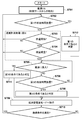
- FIG. 7 is a flowchart showing power control processing of the electronic thermometer.
- step S701 a magnet reed switch (not shown) of the electronic thermometer 100 is turned on, so that the power supply unit 250 of the electronic thermometer 100 is turned on. At this time, the electronic thermometer 100 shifts to the body temperature measurement mode.
- the power consumption at this time is, for example, about 60 ⁇ W.
- step S702 it is determined whether or not the electronic thermometer 100 has been left for a first predetermined time (for example, 10 minutes).
- a first predetermined time for example, 10 minutes.
- the process proceeds to step S712, and it is determined that the first condition is satisfied.
- the first condition is a case where the temperature measurement unit 210 is left after the start of temperature measurement.
- the determination of whether or not the temperature measurement is performed may be performed by, for example, temperature change of the temperature measurement unit 210 (steepness of a temperature gradient or Judgment is made by monitoring (temperature rise / fall). Then, it progresses to step S709 and transfers to a low consumption current mode.
- FIG. 8 is a diagram showing a state of temperature change with a series of usage modes (elapsed time) of the electronic thermometer.
- the electronic thermometer 100 after measuring the body temperature of the subject, the electronic thermometer 100 is wiped with alcohol absorbent cotton, then the body temperature of another subject is measured, washed with water, and the body temperature of another subject is further measured. It shows the temperature change when the electronic thermometer 100 is left after the measurement, after being put into the drug solution, and after measuring the body temperature of another subject.
- the temperature gradient rises according to the body temperature to be measured, and when reaching the body temperature of the subject, the temperature enters a constant temperature state. To establish. Thereafter, when the electronic thermometer 100 is collected from the subject and wiped with alcohol absorbent cotton, the temperature gradient suddenly drops due to a rapid temperature drop due to heat of vaporization (A region in the figure).
- the temperature is measured through a similar temperature change, and the electronic thermometer 100 is recovered from the subject and washed with water. Is deprived, and the temperature gradient drops relatively rapidly (B region in the figure).
- the temperature of the electronic thermometer 100 becomes constant (C region in the figure).
- the temperature is measured through the same temperature change, and the electronic thermometer 100 is collected from the subject and left to stand.
- the temperature gradually decreases with the temperature gradient (D region in the figure).
- a temperature change value indicating a temperature change within a certain time (for example, a steepness or inclination of a temperature gradient, a temperature difference), a threshold corresponding to each situation (A region to D region), and temperature measurement
- the determination is made using the temperature change value within a predetermined time obtained by the measurement of the unit 210. That is, when the temperature change value does not exceed the threshold value, it is determined that the electronic thermometer 100 is not in a state where temperature measurement should be performed in the body temperature measurement mode, and the mode is shifted to the low current consumption mode. On the other hand, when the temperature change value exceeds the threshold value, the electronic thermometer 100 determines that the body temperature measurement is to be performed in the body temperature measurement mode, and shifts to the body temperature measurement mode.
- step S703 it is determined whether or not temperature measurement is started. If it is determined that the temperature measurement is not started (NO in step S703), the process returns to step S702. On the other hand, when it is determined that the temperature detection is started (YES in step S703), the process proceeds to step S704, and it is determined whether or not the temperature detection is established. If it is determined that the temperature detection is not established (NO in step S704), the process returns to step S702. On the other hand, if it is determined that the temperature detection is established (YES in step S704), the process proceeds to step S705.
- step S703 and step S704 corresponds to the body temperature measurement process (body temperature measurement mode) in FIG.
- step S706 it is determined whether or not the electronic thermometer 100 has been charged (immersed) in the chemical solution. If it is determined that it is not put in the chemical (NO in step S705), it is determined in step S706 whether or not the electronic thermometer 100 has been left for a second predetermined time (for example, 3 minutes). If it is determined that the electronic thermometer 100 has not been left for the second predetermined time (NO in step S706), the process returns to step S705. On the other hand, when it is determined that the electronic thermometer 100 has been left for the second predetermined time (YES in step S706), the process proceeds to step S708, and it is determined that the second condition is satisfied.
- a second predetermined time for example, 3 minutes
- the second condition is when the electronic thermometer 100 is left after the temperature measurement is established, that is, when the temperature measurement unit 210 detects the state of the D region in FIG. Then, it progresses to step S709 and transfers to a low consumption current mode.
- step S705 if it is determined that the chemical solution has been introduced (YES in step S705), the process proceeds to step S711, where it is determined that the third condition is satisfied.
- the third condition is when the electronic thermometer 100 is immersed in the chemical solution, that is, when the temperature measurement unit 210 detects the state of the region C in FIG. Then, it progresses to step S709 and transfers to a low consumption current mode.
- step S704 the determination that it has been introduced into the chemical solution is performed after the temperature detection is established. However, even before the temperature measurement is established, the determination is made that the predetermined condition is satisfied. It is also possible to shift to the low current consumption mode.
- the transition to the low current consumption mode is performed using the temperature change detected by the temperature measurement unit 210, but the physical external force (inclination) acting on the electronic thermometer 100 detected by the sensor unit 260. It is also possible to shift to the low current consumption mode by determining whether or not to leave.
- This low current consumption mode is a mode for reducing the power consumption of the power supply unit 250, which is lower than the power consumption in the body temperature measurement mode, as described above. At this time, for example, power consumption is about 10 ⁇ W to 30 ⁇ W. Although a specific method for realizing low power consumption will be described later, power consumption varies depending on the method. Note that more power can be saved by performing a plurality of methods simultaneously.
- step S710 After shifting to the low current consumption mode, in step S710, it is determined whether or not the current state of the electronic thermometer 100 satisfies the return condition as described above. If it is determined that the return condition is not satisfied (NO in step S710), the process returns to step S709. On the other hand, when it is determined that the return condition is satisfied (YES in step S710), the low current consumption mode is returned to the body temperature measurement mode, and the process returns to step S702.
- Temperature measurement is stopped, and the display on the display unit 104 is fixed at the temperature at the time of measurement. Fixing this display means displaying / blinking / inverting an indicator (specific image, mark, text string) indicating that the measurement is stopped, or changing the background color / brightness or blacking out. Etc.
- the temperature measurement does not stop, but the display content on the display unit 104 blinks / extinguishes (reduction of current consumption necessary for display).
- the operating frequency of the electronic thermometer 100 is slowed (the slower the operating frequency, the smaller the current consumption).
- the current consumption during charging can be reduced by reducing the capacitance of the capacitor 403 or by switching the capacitor 403 to be selected according to temperature by having a plurality of capacitors 403. .
- the threshold value of the comparator 421 for example, from 0.25 Vcc to 0.5 Vcc
- the discharge time is shortened, and as a result, current consumption can be reduced.
- the electronic thermometer 100 even if the electronic thermometer 100 is left after the temperature measurement, it is desirable to store the temperature measurement result as the previous value in the RAM 226 so that the latest temperature measurement result can be confirmed immediately. By doing in this way, even in the low current consumption mode, the latest temperature measurement result (previous value) stored in the RAM 226 can be fixedly displayed on the display unit 104.
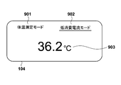
- FIG. 9 shows a display example of the display unit 104 in the low current consumption mode in such a case.
- the display unit 104 displays an index 901 indicating the body temperature measurement mode, an index 902 indicating the low current consumption mode, and a temperature value 903 to be displayed in each mode.
- an underline image is displayed under the index 901 or the index 902 to indicate which mode is the current mode.
- FIG. 9 shows a case where the current state is the low current consumption mode.
- the temperature value 903 that is the latest temperature measurement result (previous value) stored in the RAM 226 is displayed.
- the measured temperature may be displayed.
- the electronic thermometer 100 is attached to the subject's armpit, and the subject himself / herself displays the display unit 104. Since it is not easy to visually recognize the temperature, it is not always necessary to display the temperature during the temperature measurement. To the last, in the body temperature measurement mode, it is sufficient that the finally determined temperature value is displayed when the temperature measurement is established.
- the state of the electronic thermometer (stand, immersion, etc.) is determined by monitoring the temperature change within a certain time, and the body temperature is measured according to the determination state. Transition from mode to low current consumption mode. Thereafter, when the state of the electronic thermometer is in a state where the temperature should be measured, the state quickly shifts to the body temperature measurement mode.
- mode switching can be performed adaptively, the power saving of an electronic thermometer, in other words, improvement of a battery life can be aimed at.
- ⁇ Other embodiments> the configuration for switching the mode between the body temperature measurement mode and the low current consumption mode has been described, but the present invention is not limited to this. Further, in addition to these modes, a conventional auto power-off may be made to function. For example, when the mode is left for a long time (for example, 3 hours or more) after shifting to the low current consumption mode, the auto power off function may be functioned to further save power.
- the display unit 104 is configured to display an index indicating whether the body temperature measurement mode or the low current consumption mode and the temperature to be displayed in each mode are displayed. It is not limited to.
- the voice output unit 240 may provide voice guidance of which mode is the current mode and the temperature to be output in each mode. However, in this case, a configuration for outputting sound is required. For example, by providing an acceleration sensor or a contact sensor in the sensor unit 260 to give vibration or contact to an object to the electronic thermometer 100, mode information indicating a mode at that time and a temperature to be output corresponding to the mode Information may be output by voice.
Landscapes
- Physics & Mathematics (AREA)
- General Physics & Mathematics (AREA)
- Measuring Temperature Or Quantity Of Heat (AREA)
Abstract
電子体温計の温度変化を検知し、検知する温度変化に基づいて、電源がすでにONされ、体温測定モードの状態にある当該電子体温計が、該体温測定モードによる体温測定をすべき状態にあるか否かを判定する。判定の結果、電子体温計が体温測定モードによる体温測定をすべき状態にないと判定された場合、体温測定モードを、該体温測定モードにおける消費電力よりも低い電力で動作させる低消費電流モードへ移行する。
Description
本発明は、電子体温計に関するものである。
病院用体温計は、感染予防のために、薬液に浸漬させて消毒することがある。そのため、体温計の内部に薬液が侵入しないように、体温計を密封している。そして、マグネットリードスイッチを利用して、体温計の収納ケースへの出し入れによって電源ON/OFFさせている。ここで、体温計は、密封構造の筺体で形成されているので、電池交換できない仕様になっている。
しかしながら、収納ケースから出した状態で、体温計が放置されると、常時通電状態となるため、電池が消耗してしまう。
そこで、この種の体温計では、一定時間経過後にオートパワーオフするようにしたり、体温計の外部筺体部分にスイッチをつけたりすることで、低消費電流に移行させる工夫がなされている。
例えば、特許文献1では、温度が低い場合、次の検温まで時間があると判定し、クロックを落とすことで、消費電流を低減させる構成が開示されている。
しかしながら、従来の構成では、オートパワーオフさせてしまうと、検温結果が分からなくなってしまう。これに対して、検温結果を前回値として記憶することも可能であるが、次回の測定時に前回値を長時間表示する仕様としてしまうと、次の検温結果と混同する可能性があるのと、測定環境範囲外表示などを表示できない等の不都合がある。このため、現状では、長時間表示できない(数秒で次の表示に切り替わる)仕様となっているため、正確な検温結果を転記したり把握することができない。更に、体温計の外部筺体部分にスイッチをつけるためには、液密性を保つための機構が必要となり、コストがかかる要因となる。
また、特許文献1の構成では、検温時の温度値に応じて、その動作クロックを制御することにより検温時の消費電流を低減させるものである。従って、なんらかの事情で検温までの開始時間が遅くなる場合や、検温後、収納ケースに収納されないまま放置されるような場合における消費電流の節減については考慮されていない。
通常、病院用の体温計は、収納ケースから出された後は、すぐに検温が開始されることを想定しているため、収納ケースから出された後は直ちに検温時(測定モード)のサンプリング状態となっている。つまりは、病院用の体温計は、検温開始までの間や、検温終了後に収納ケースに体温計が収納されるまでの放置されている時間期間の消費電流を低減するための工夫はなされていない。
また、検温結果を維持し有効に活用するという観点では、オートパワーオフが働くまでの時間期間以降でも、その検温結果を維持することができる程度の低電力で体温計がONされていることが望ましい。
本発明は上記課題に鑑みてなされたものであり、電子体温計の使用状態に応じて、より適切な電力制御を行うことで、コストをかけることなく、電池寿命を改善することができる電子体温計及びその制御方法を提供することを目的とする。
上記の目的を達成するために本発明に係る電子体温計は以下のような構成を備える。即ち、
電子体温計であって、
前記電子体温計の温度変化を検知する検知手段と、
前記検知手段が検知する温度変化に基づいて、電源がすでにONされ、体温測定モードの状態にある当該電子体温計が、該体温測定モードによる体温測定をすべき状態にあるか否かを判定する判定手段と、
前記判定手段の判定の結果、前記電子体温計が前記体温測定モードによる体温測定をすべき状態にないと判定された場合、前記体温測定モードを、該体温測定モードにおける消費電力よりも低い電力で動作させる低消費電流モードへ移行する移行手段と
を備える。
電子体温計であって、
前記電子体温計の温度変化を検知する検知手段と、
前記検知手段が検知する温度変化に基づいて、電源がすでにONされ、体温測定モードの状態にある当該電子体温計が、該体温測定モードによる体温測定をすべき状態にあるか否かを判定する判定手段と、
前記判定手段の判定の結果、前記電子体温計が前記体温測定モードによる体温測定をすべき状態にないと判定された場合、前記体温測定モードを、該体温測定モードにおける消費電力よりも低い電力で動作させる低消費電流モードへ移行する移行手段と
を備える。
本発明によれば、電子体温計の使用状態に応じて、より適切な電力制御を行うことで、コストをかけることなく、電池寿命を改善することができる電子体温計及びその制御方法を提供できる。
本発明のその他の特徴及び利点は、添付図面を参照とした以下の説明により明らかになるであろう。なお、添付図面においては、同じ若しくは同様の構成には、同じ参照番号を付す。
添付図面は明細書に含まれ、その一部を構成し、本発明の実施の形態を示し、その記述と共に本発明の原理を説明するために用いられる。
本実施形態の電子体温計とその収納ケースの外観を示す図である。
本実施形態の電子体温計の機能構成を示す内部ブロック図である。
電子体温計における体温計測処理を示すフローチャートである。
温度計測部の詳細構成を示す図である。
温度計測処理の詳細を示すフローチャートである。
コンデンサの両端の電圧の時間変化及びA/D変換部より出力されるディジタル信号の時間変化を示す図である。
電子体温計の電力制御処理を示すフローチャートである。
電子体温計の一連の使用態様(時間経過)に伴う温度変化の様子を示す図である。
低消費電流モード時の表示部の表示例を示す図である。
以下、必要に応じて添付図面を参照しながら本発明の実施形態を詳細に説明する。尚、以下に述べる実施の形態は、本発明の好適な具体例であるから、技術的に好ましい種々の限定が付されているが、本発明の範囲は、以下の説明において特に本発明を限定する旨の記載がない限り、これらの態様に限られるものではない。
<1.電子体温計の外観構成>
図1は本実施形態の電子体温計とその収納ケースの外観を示す図である。
図1は本実施形態の電子体温計とその収納ケースの外観を示す図である。
図1の1aに示すように、収納ケース120は容器本体である収納部122とキャップ部材としての蓋部121とを有する。収納ケース120はプラスチックにて作られている。蓋部121は回動部15を介して収納部122に取り付けられており、回動部15により回動して収納ケース120の開閉を可能にしている。蓋部121を、例えば、透明な部材で形成すれば、収納ケース120に電子体温計100(図1の1b)が収納されているか否かを直ちに視認することができる。収納部122の上面パネルには窓13が設けられている。使用者は、収納ケース120の内部空間に収納された電子体温計100の表示部104を外部から見ることができる。使用者は、窓13により収納ケース120に電子体温計100が収納されているか否かを知ることができる。但し、上述したように蓋部121を透明にした場合、窓13を省略することもできる。
図1の1bに示すように、蓋部121を回動させると、収納部122の内部空間へ電子体温計100の抜き差しを行うための開口14が露出する。収納ケース120への電子体温計100の収納時には、電子体温計100はエンドキャップ103の側から収納部122の内部空間へ挿入される。例えば、収納部122は、射出成形により、上面パネル、下面パネル、側面パネルを一体的に成形して得られる。収納部122は、耐衝撃性の熱可塑性樹脂、例えば、ハイインパクト・スチロール樹脂、ABS樹脂などのスチレン系樹脂等で形成されている。
尚、図1の1bでは、収納ケース120は、1本の電子体温計100を収納する構成となっているが、これに限定されない。例えば、図1の1cに示すように、複数本(2,4,6,8,10、、等の単位数)の電子体温計100を収納することが可能な収納ケースであっても良い。特に、図1の1cでは、2列構成で各列が5本、計10本の電子体温計100を収納できる収納ケースの一例を示している。
次に、図1の1bを参照して、本実施形態に係る電子体温計100の外観構成を説明する。図1の1bには、電子体温計100を収納部122に挿入する概念図とともに、本実施形態による電子体温計100の外観斜視図が示されている。
図1の1bにおいて、101は電子体温計100の本体ハウジング(筐体101)である。筐体101は、耐衝撃性の熱可塑性樹脂、例えば、ハイインパクト・スチロール樹脂、ABS樹脂などにより形成されている。103はエンドキャップである。エンドキャップ103は、内蔵された温度計測部に対して被検者の体温が伝導しやすいように、ステンレス等の金属により被覆されている。エンドキャップ103の内部には温度を計測するためのサーミスタ等の温度計測部が収納され、液密性を有している。104は体温測定結果として体温データ等のデータを表示する表示部であり、透明の熱可塑性樹脂で形成された窓部材104aにより覆われている。窓部材104aは、筐体101と二色成形され、高い液密性を有している。
<2.電子体温計の機能構成>
図2は本実施形態の電子体温計100の機能構成を示す内部ブロック図である。
図2は本実施形態の電子体温計100の機能構成を示す内部ブロック図である。
本実施形態の電子体温計100は、その動作モードとして、被検者の体温を計測する通常の体温測定モードに加えて、電子体温計100が放置されていると判定される場合の期間の消費電力を低減するための低消費電流モードを有する。この低消費電流モードは、体温測定モードにおける消費電力よりも低い電力で動作させるモードである。
電子体温計100は、温度に対応した時間分のON信号を出力する温度計測部210と、温度計測部210より出力されたON信号に基づいて各種処理を行い、被検者の体温を演算すると共に電子体温計100全体の動作を制御する演算制御部220とを備える。更に、電子体温計100は、演算された被検者の体温を表示する表示部104と、音声データを出力する音声出力部240と、電源部250、及びセンサ部260とを備える。
尚、表示部104は、例えば、体温等の計測情報を表示するための液晶表示部で構成される。また、この表示部104では、計測情報に加えて、電子体温計100のステータス情報(例えば、低消費電流モード、体温測定モード等)を表示することが可能である。
温度計測部210は、エンドキャップ103の内部に配置された、互いに並列に接続されたサーミスタ(測定用抵抗素子)及び基準抵抗素子と、単一入力積分型A/D変換回路とを備える。そして、温度計測部210は、温度に対応した時間分のON信号(温度に対応して、ON時間が変わるディジタル信号)を出力する。尚、温度計測部210の詳細構成及び温度計測処理の詳細については後述する。また、本実施形態では、温度計測部210の温度測定方式に積分方式を採用しているが、これに限定されるものではなく、他の方式、例えば、CR発振回路を利用するCR発振方式を用いても良い。
演算制御部220は、温度計測部210より出力されるディジタル信号のON時間を計測するタイマー222を備える。また、タイマー222では、電源部250がONされてからの時間を計測することも可能である。このように、演算制御部220は、所定の条件に応じて、タイマー222のON/OFF、リセットを制御することが可能である。そのため、演算制御部220は、所定の条件として、タイマー222の計測時間に基づいて、上述の体温測定モードと低消費電流モードとを切り替えることが可能となる。
また、演算制御部220は、ROM224、EEPROM225及びRAM226を備える。ROM224は、タイマー222により計測された時間に基づいて温度データを算出するとともに、算出された温度データの時間変化に基づいて、被検者の体温を予測演算するプログラムを記憶している。RAM226は、算出された温度データを時系列で記憶する。EEPROM225は、所定の音声データ、校正値、検体番号、エラー情報、測定回数などを記憶する。
また、演算制御部220は、ROM224に格納されたプログラムに従った演算や音声データの出力を行う演算処理部223と、演算処理部223における演算結果を表示する表示部104を制御するための表示制御部227を備える。更に、演算制御部220は、タイマー222、表示制御部227、演算処理部223、温度計測部210及びセンサ部260を制御する制御回路221を備える。
センサ部260は、電子体温計100の状態を検出するためのセンサである。このセンサには、電子体温計100の環境温度を検出する温度センサや、電子体温計100に働く物理的な外力(傾斜や振動)を検出する加速度センサや傾斜/振動スイッチ、電子体温計100への物体の接触を検出するコンタクトセンタ等がある。これらのセンサは、低消費電流モードに移行している体温計を通常の体温測定モードに復帰するための状態検出を行うために使用するものであり、仕様に応じて、適宜、必要なセンサを実装することになる。
尚、センサ部260に温度センサを実装する代わりに、温度計測部210によって、電子体温計100の環境温度を検出することも可能である。
また、電子体温計100には、マグネットリードスイッチ(不図示)が設けられている。このため、電子体温計100が収納ケース120から出されるとマグネットリードスイッチがONされ、電源部250から演算制御部220、温度計測部210、表示部104等の各種構成要素に電源が供給され続けられることになる。そして、電子体温計100が永久磁石を内蔵した収納ケース120に収納されると、電源の供給が遮断され、電源がOFF状態となる。
<3.電子体温計における体温計測処理>
まず、上述の体温測定モードで実行する、電子体温計における体温計測処理について説明する。尚、ここでは、平衡温予測式の電子体温計100の体温計測処理について説明するが、本発明はこれに限定されず、実測式の電子体温計、予測/実測式の電子体温計にも適用可能である。
まず、上述の体温測定モードで実行する、電子体温計における体温計測処理について説明する。尚、ここでは、平衡温予測式の電子体温計100の体温計測処理について説明するが、本発明はこれに限定されず、実測式の電子体温計、予測/実測式の電子体温計にも適用可能である。
電子体温計100が被検者の計測部位に装着されると、電子体温計100では、所定の周期(サンプリングレート)で温度計測を開始し、取得された温度データの時間変化に基づいて、被検者の体温を予測演算する。
図3は電子体温計100における体温計測処理を示すフローチャートである。
電子体温計100の電源部250がONされると、ステップS301で、電子体温計100の初期化が行われ、サーミスタによる温度計測が開始される。例えば、演算処理部223では、体温計測用のサンプリングレートとして、所定間隔、例えば、0.5秒おきに温度データの演算が行われる。
ステップS302で、体温計測開始条件が成立したか否かを判定する。具体的には、前回の温度計測により演算された温度データの値(つまり、0.5秒前の温度データの値)からの上昇度が、所定値(例えば、1℃)以上となったか否かを判定する。
上昇度が所定値以上となったと判定した場合には、体温計測開始条件が成立したと判定し、当該温度データを計測したタイミングを、予測体温演算の基準点(t=0)として設定する。つまり、電子体温計100では、急激な温度上昇が計測されると、被検者が、所定の計測部位(例えば、腋下)に電子体温計100を装着したものとみなす。
ステップS302で、体温計測開始条件が成立したと判定した場合(ステップS302でYES)、ステップS303に進み、温度データの取込を開始する。具体的には、出力された温度データと、当該温度データを計測したタイミングとを、時系列データとしてRAM226に記憶する。一方、体温計測開始条件が成立していないと判定した場合(ステップS302でNO)、体温計測開始条件が成立したと判定されるまで待機する。あるいは、一定時間以上経過した場合には、計測エラーとして、後述する低消費電流モードに移行しても良い。
ステップS304で、ステップS303においてRAM226に記憶された温度データを用いて、所定の予測式により、予測体温を演算する。
ステップS305で、基準点(t=0)から所定時間(例えば、25秒)経過した後に、ステップS304において算出された一定区間(例えば、t=25~30秒)における予測値が、予め設定された予測成立条件を満たすか否かを判定する。具体的には、予測値が、所定の範囲(例えば、0.1℃)以内に収まっているか否かを判定する。
ステップS305で、予測成立条件を満たすと判定した場合(ステップS305でYES)、ステップS306に進み、温度計測を終了する。次に、ステップS307で、予測体温の演算が終了した旨の音声を出力し、表示部104に、演算された予測体温を計測値の体温として表示する。
一方、ステップS305で、予測成立条件を満たさないと判定した場合(ステップS305でNO)、ステップS309に進む。ステップS309で、基準点(t=0)から所定時間(例えば45秒)経過したか否かを判定し、経過したと判定した場合には、温度計測を強制終了する。尚、強制終了した場合には、その際に演算されていた予測体温を、表示部104に表示する(ステップS307)。
尚、ステップS307の後、つまり、予測検温が成立した後に、電子体温計100が収納ケース120に収納された場合には、電子体温計100のマグネットリードスイッチがOFFし、電源部250からの電源供給がOFFされる。
<4.温度計測部の詳細構成>
図4は温度計測部210の詳細構成を示す図である。
図4は温度計測部210の詳細構成を示す図である。
図4に示すように、温度計測部210では、サーミスタ401及び基準抵抗素子402が、それぞれ、コンデンサ403に接続されている。コンデンサ403は、電圧切替部410からサーミスタ401ないし基準抵抗素子402を介して電圧Vに充電されるが、図示されない充電用の抵抗素子を介して充電してもよい。次に、コンデンサ403に充電された電荷は、サーミスタ401が接続されている電圧切替部410をGNDレベルに落とす、ないし基準抵抗素子402が接続されている電圧切替部410をGNDレベルに落とすことで、それぞれサーミスタ401ないし基準抵抗素子402を介して放電される。なお、放電の際には、放電に使われない電圧切替部410の出力はハイインピーダンスに切り替えられる。
ここで、基準抵抗素子402は、周辺温度の変動に関わらず、抵抗値が一定の抵抗素子である。このため、電圧Vが一定の場合、基準抵抗素子402を介して放電された場合の放電時間は一定となる。
一方、サーミスタ401は、周辺温度の変動に応じて、抵抗値が変動する抵抗素子である。このため、サーミスタ401を介して放電された場合の放電時間は、周辺温度に応じて変動する。
つまり、電圧Vが一定の場合、基準抵抗素子402を介して放電された場合にあっては、放電時間は常に一定となり、サーミスタ401を介して放電された場合にあっては、放電時間は周辺温度に依存することとなる。
コンデンサ403に蓄積された電荷量は、A/D変換部420を介して検出される。A/D変換部420を構成するコンパレータ421は、電圧切替部410を介して印加された電圧Vの所定割合の電圧(ここでは、0.25V)以上の電圧をコンデンサ403が有している間、所定の信号を出力する。これにより、A/D変換部420からは、ディジタル信号として、ON信号が出力される。
このように、コンデンサ403とA/D変換部420とは、単一入力積分型A/D変換回路を形成する。
放電されることにより、コンデンサ403両端の電圧は、徐々に低下していき、所定の電圧(0.25V)以下になると、A/D変換部420より出力されるディジタル信号はOFF信号となる。
タイマー222では、A/D変換部420より出力されるディジタル信号のON時間(放電時間)を計測する。
ここで、上述のように、基準抵抗素子402を介して放電された場合にあっては、放電時間は一定となる。一方、サーミスタ401を介して放電された場合にあっては、抵抗値が周辺温度に応じて変動するため、放電時間も変動する。
そこで、電子体温計100では、周辺温度が既知の状態(基準温度)で、サーミスタ401を介してコンデンサ403に蓄積された電荷を放電した場合の放電時間を計測しておく。これに加えて、電子体温計100では、基準抵抗素子402を介してコンデンサ403に蓄積された電荷を放電した場合の放電時間を計測しておく。
この結果、基準抵抗素子402を介してコンデンサ403に蓄積された電荷を放電した際の放電時間と、サーミスタ401を介してコンデンサ403に蓄積された電荷を放電した際の放電時間とを比較するだけで、基準温度に対する変動比を算出できる。また、温度データも算出できる。
具体的には、下式に基づいて、計測された温度における規格化された放電時間Tを算出する。メモリには、放電時間と温度の対応関係を表すテーブルが記録されており、この規格化された放電時間Tをテーブルと照らし合わせることで温度に換算する。
T=T37×(Tth/Tref)×(Tref37/Tth37)
尚、上式において、基準温度は37℃としている。また、Tref37は、当該基準温度において、基準抵抗素子402を介して放電した場合に計測された放電時間を示している。更に、Tth37は、当該基準温度において、サーミスタ401を介して放電した場合に計測された放電時間を示している。
尚、上式において、基準温度は37℃としている。また、Tref37は、当該基準温度において、基準抵抗素子402を介して放電した場合に計測された放電時間を示している。更に、Tth37は、当該基準温度において、サーミスタ401を介して放電した場合に計測された放電時間を示している。
また、Trefは、温度計測処理において、基準抵抗素子402を介して放電した場合に計測した放電時間を示している。更に、Tthは、温度計測処理において、サーミスタ401を介して放電した場合に計測した放電時間を示している。T37は、基準温度での、規格化のための基準となる抵抗値を介した場合に得られる放電時間を示している。
<5.温度計測処理の詳細>
図5は温度計測処理の詳細を示すフローチャートである。図6はコンデンサ403の両端の電圧の時間変化及びA/D変換部420より出力されるディジタル信号の時間変化を示す図である。図5及び図6を用いて、一般的な温度計測処理について説明する。
図5は温度計測処理の詳細を示すフローチャートである。図6はコンデンサ403の両端の電圧の時間変化及びA/D変換部420より出力されるディジタル信号の時間変化を示す図である。図5及び図6を用いて、一般的な温度計測処理について説明する。
ステップS501で、コンデンサ403を充電する。図6の601は、コンデンサ403に徐々に電荷が蓄積されていく期間(充電期間)を示している。
コンデンサ403の充電が完了すると、ステップS502で、コンデンサ403の放電を行う(放電期間602)。このとき、A/D変換部420からは、ON信号が出力されるため(603)、タイマー222では、ON信号の時間を計測する。これにより、放電を開始してからコンデンサ403の電圧が所定の電圧(ここでは、0.25V)以下になるまでの時間(放電時間604)Trefが計測される(図6の602参照)。
コンデンサ403の放電が完了すると、ステップS503で、再びコンデンサ403を充電する。図6の605は、コンデンサ403に徐々に電荷が蓄積されていく期間(充電期間)を示している。
コンデンサ403の充電が完了すると、ステップS504で、コンデンサ403の放電を行う(放電期間606)。このとき、A/D変換部420からは、ON信号が出力されるため(607)、タイマー222では、ON信号の時間を計測する。これにより、放電を開始してからコンデンサ403の電圧が所定の電圧(ここでは0.25V)以下になるまでの時間(放電時間608)Tthが計測される。尚、Tthは、サーミスタ401の周辺温度に応じて変動する。
コンデンサ403の放電が完了すると、ステップS505で、T=a×Tth/Tref(ただし、aは係数であり、ここでは、a=T37×(Tref37/Tth37))を計算することで、基準温度に対する変動比を求め、規格化された放電時間を算出する。更に、ステップS506で、規格化された放電時間Tを温度測定結果に換算する。
これにより、1回の温度計測が完了する。当該温度計測処理は、温度計測の終了が指示されるまで繰り返し行われる。
<6.低消費電流モード機能付き電力制御>
次に、本実施形態の特徴的な構成である、低消費電流モード(省電力モード)と体温測定モードを適応的に切り替えることで、電子体温計100の電力消費を低減するための電力制御処理について説明する。
次に、本実施形態の特徴的な構成である、低消費電流モード(省電力モード)と体温測定モードを適応的に切り替えることで、電子体温計100の電力消費を低減するための電力制御処理について説明する。
通常、収納ケース120から電子体温計100が出されると、体温測定モードとして、図3の体温計測処理の準備に入ることになる。これに対し、本実施形態では、以下のような要因を想定して、体温測定モードから低消費電流モードに移行する。低消費電流モードに移行する移行条件としては
1.検温開始もしくは成立する前に、電子体温計100が放置された場合
2.検温後に、薬液の中に浸けたり、電子体温計100が洗浄された場合
3.回診時に、検温したが、医療従事者(看護師等)が回収にくるまでに一定時間が経過(放置)してしまった場合
を想定する。もちろん、これ以外の様々な要因を想定して、それを移行条件とすることも可能である。換言すれば、電子体温計100が体温測定モードによる体温測定をすべき状態でない場合に、低消費電流モードに移行する。
1.検温開始もしくは成立する前に、電子体温計100が放置された場合
2.検温後に、薬液の中に浸けたり、電子体温計100が洗浄された場合
3.回診時に、検温したが、医療従事者(看護師等)が回収にくるまでに一定時間が経過(放置)してしまった場合
を想定する。もちろん、これ以外の様々な要因を想定して、それを移行条件とすることも可能である。換言すれば、電子体温計100が体温測定モードによる体温測定をすべき状態でない場合に、低消費電流モードに移行する。
一方、低消費電流モードに移行した後、その低消費電流モードから体温測定モードに復帰するための復帰条件としては、
1.温度変化を検知した場合、
2.復帰をトリガーするための割込を検知した場合、
3.1と2の組み合わせ
を想定する。
1.温度変化を検知した場合、
2.復帰をトリガーするための割込を検知した場合、
3.1と2の組み合わせ
を想定する。
尚、復帰条件1における「温度変化:とは、電子体温計100の周辺環境の温度の上昇や、一定温度状態にある温度の変動幅が一定量崩れた場合を意味する。この温度変化の検知は、温度計測部210による検知の他、センサ部260に別途、実装する専用の温度センサによって実現することができる。
また、復帰条件2における「復帰をトリガーするための割込」とは、例えば、センサ部260に実装する加速度センサや傾斜スイッチ、振動スイッチが電子体温計100の傾斜や振動を検知した際に演算制御部220に発行する信号による割込を意味する。また、あるいは、センサ部260に実装するコンタクトセンサが電子体温計100に対する接触を検知した際に演算制御部220に発行する信号による割込を意味する。いずれにしても、体温測定モードに移行すべき状況を検知することができるセンサによる出力の有無に基づいて、体温測定モードへ移行する。
以上の前提を踏まえて、図7を用いて、本実施形態の低消費電流を実現する電力制御処理について説明する。
図7は電子体温計の電力制御処理を示すフローチャートである。
ステップS701で、電子体温計100のマグネットリードスイッチ(不図示)がON状態になることで、電子体温計100の電源部250がONされる。この時点では、電子体温計100は体温測定モードに移行する。このときの消費電力は、例えば、60μW程度である。
ステップS702で、電子体温計100が第1の所定時間(例えば、10分)放置されたか否かを判定する。電子体温計100が第1の所定時間、放置されていると判定した場合(ステップS702でYES)、ステップS712に進み、第1の条件であると判定する。ここで、第1の条件とは、検温開始後に放置された場合であり、放置されたか否かの判定は、例えば、温度計測部210の温度変化(温度勾配の急峻度や一定温度状態からの温度上昇/降下)を監視することで判定する。その後、ステップS709に進み、低消費電流モードへ移行する。
ここで、移行条件となる温度変化の一例について、図8を用いて説明する。
図8は電子体温計の一連の使用態様(時間経過)に伴う温度変化の様子を示す図である。
図8では、被検者の体温を計測後、電子体温計100をアルコール脱脂綿で拭き、次に、別の被検者の体温を計測後、水で洗浄し、更に別の被検者の体温を計測後、薬液に投入し、その後、更に別の被検者の体温を計測後、電子体温計100を放置した場合の温度変化を示している。
電子体温計100を収納ケース120から取り出し、被検者の体温の計測を開始すると、温度勾配は計測する体温に応じて上昇し、被検者の体温までに到達すると一定温度状態に入り、検温が成立する。その後、被検者から電子体温計100を回収し、アルコール脱脂綿で拭くと、気化熱による急激な温度低下により、その温度勾配は急降下する(図中のA領域)。
その後、別の被検者の体温の計測を開始すると、同様な温度変化を経て、検温が成立し、被検者から電子体温計100を回収し、水で洗浄すると、水流によって電子体温計100の熱が奪われ、その温度勾配が比較的急激に降下する(図中のB領域)。
その後、更に別の被検者の体温の計測を開始すると、同様な温度変化を経て、検温が成立し、被検者から電子体温計100を回収し、薬液に浸けると、その薬液の温度に近い温度で電子体温計100は一定温度状態になる(図中のC領域)。
その後、また、更に別の被検者の体温の計測を開始すると、同様な温度変化を経て、検温が成立し、被検者から電子体温計100を回収し、放置すると、電子体温計100は緩やかな温度勾配で温度が逓減する(図中のD領域)。
以上のような、A領域~D領域の状態を温度計測部210によって検知することで、低消費電流モードに移行するための移行条件を判定することが可能となる。具体的には、一定時間内での温度変化を示す温度変化値(例えば、温度勾配の急峻度や傾き、温度差)を、各状況(A領域~D領域)に応じた閾値と、温度計測部210の測定によって得られる一定時間内の温度変化値とを用いて判定する。つまり、温度変化値が閾値を超えない場合に、電子体温計100が体温測定モードによる体温測定をすべき状態にないと判定して、低消費電流モードに移行する。一方、温度変化値が閾値を超える場合に、電子体温計100は体温測定モードによる体温測定をすべき状態にあると判定して、体温測定モードに移行する。
図7の説明に戻る。
電子体温計100が第1の所定時間、放置されていないと判定した場合(ステップS702でNO)、ステップS703に進み、検温開始であるか否かを判定する。検温開始でないと判定した場合(ステップS703でNO)、ステップS702に戻る。一方、検温開始であると判定した場合(ステップS703でYES)、ステップS704に進み、検温成立であるか否かを判定する。検温成立でないと判定した場合(ステップS704でNO)、ステップS702に戻る。一方、検温成立であると判定した場合(ステップS704でYES)、ステップS705に進む。
尚、このステップS703とステップS704の処理が、図3の体温計測処理(体温測定モード)に対応する。
次に、電子体温計100が薬液に投入(液浸)されたか否かを判定する。薬液に投入されていないと判定した場合(ステップS705でNO)、ステップS706で、電子体温計100が第2の所定時間(例えば、3分)放置されたか否かを判定する。電子体温計100が第2の所定時間、放置されていないと判定した場合(ステップS706でNO)、ステップS705に戻る。一方、電子体温計100が第2の所定時間、放置されていると判定した場合(ステップS706でYES)、ステップS708に進み、第2の条件であると判定する。ここで、第2の条件とは、検温成立後に電子体温計100が放置された場合、つまり、温度計測部210が図8のD領域の状態を検知した場合である。その後、ステップS709に進み、低消費電流モードへ移行する。
一方、薬液に投入されたと判定した場合(ステップS705でYES)、ステップS711に進み、第3の条件であると判定する。ここで、第3の条件とは、電子体温計100が薬液に浸された場合、つまり、温度計測部210が図8のC領域の状態を検知した場合である。その後、ステップS709に進み、低消費電流モードへ移行する。
尚、ここでは、薬液に投入されたとの判定は、検温成立後(ステップS704でYES)に行うよう記載されているが、検温成立前であっても所定の条件を満たすことで薬液に投入されたと判断し、低消費電流モードへ移行させることも可能である。
また、上記実施形態では、低消費電流モードへの移行は、温度計測部210によって検知する温度変化を用いて行ったが、センサ部260によって検知される電子体温計100に働く物理的な外力(傾斜や振動)をもちいて放置を判断し、低消費電流モードへ移行させることも可能である。
この低消費電流モードとは、上述のように、体温測定モードにおける消費電力よりも低い電力にする、電源部250の省電力化を図るモードである。このとき、例えば、消費電力は10μW~30μW程度である。低消費電力を実現する具体的な方法を後述するが、その方法によって消費電力も異なる。なお、複数の方法を同時に行うことで、より多くの省電力化を図ることができる。
低消費電流モードに移行後、ステップS710で、電子体温計100の現在の状態が、上述のような復帰条件を満足するか否かを判定する。復帰条件を満足しないと判定した場合(ステップS710でNO)、ステップS709に戻る。一方、復帰条件を満足すると判定した場合(ステップS710でYES)、低消費電流モードから体温測定モードへと復帰し、ステップS702に戻る。
<7.低消費電流モードの具体例>
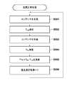
低消費電流を実現する具体的な方法としては、例えば、以下のようなものがある。
低消費電流を実現する具体的な方法としては、例えば、以下のようなものがある。
A.測定間隔(サンプリングレート)を長くする。例えば、体温測定モード時の0.5秒から1秒、2秒、5秒、10秒、、、へとサンプリングレートを変更する。
B.温度計測(サンプリング)を停止し、その計測時の温度で表示部104の表示を固定する。この表示の固定とは、測定が停止中であることを示す指標(特定の画像、マーク、テキスト文字列)を表示/ブリンク/反転表示させたり、もしくは、背景色/輝度の変更、ブラックアウトさせる等がある。
C.温度計測(サンプリング)は停止しないが、表示部104での表示内容を点滅/消灯する(表示に必要な消費電流の低減)。
D.電子体温計100の動作周波数を遅くする(動作周波数が遅い方が、消費電流は少なくなる)。
E.温度測定の分解能を低下させる。
例えば、図4に示す測定方式が積分方式の場合、コンデンサ403の容量を減らしたり、コンデンサ403を複数持ち、温度によって選択するコンデンサ403を切り替えることで、充電時の消費電流を低減することができる。あるいは、コンパレータ421の閾値(例えば、0.25Vccから0.5Vcc)を上げることで、放電時間が短くなり、結果的に、消費電流を低減することができる。
尚、CR発振方式の場合、CR発振回路を構成する回路素子(トランジスタ)のゲート長を短くすることで、消費電流を抑制することができる。
F.基準抵抗素子の測定を停止する。厳密な検温が要求されないタイミングにおいては、基準抵抗素子の放電時間は略一定となるため、測定を停止する。そして、前回測定した基準抵抗素子の放電時間の値を使用する。
以上のような、A~Fの項目を単独、もしくは組み合わせて低消費電流を実現する。もちろん、これらの項目は一例であり、低消費電流を図ることができる構成であれば、これらの項目に限定されないことは言うまでもない。用途や目的に応じて、低消費電流を図るために必要な構成を適宜採用すればよい。
但し、上述のように、検温後に電子体温計100が放置されたとしても、直近の検温結果を直ぐに確認できるように、検温結果を前回値としてRAM226に記憶しておくことが望ましい。このようにすることで、低消費電流モードにおいても、表示部104において、RAM226に記憶されている直近の検温結果(前回値)を固定的に表示することが可能となる。
ここで、このような場合での、低消費電流モード時の表示部104の表示例を、図9に示す。
図9では、表示部104では、体温測定モードであることを示す指標901と、低消費電流モードであることを示す指標902、各モードで表示すべき温度値903を表示している。図9において、現在のモードがどちらのモードであるかを示すために、指標901あるいは指標902の下に下線画像が表示される。図9では、現在の状態が低消費電流モードにある場合を示している。
低消費電流モード時には、RAM226に記憶されている直近の検温結果(前回値)である温度値903を表示する。一方、体温測定モード時には、計測されている温度を表示するようにしても良いが、通常は、被検者の腋下に電子体温計100が装着されていて、被検者自身がその表示部104を視認することは容易ではないので、必ずしも検温中の温度表示は必須ではない。あくまでも、体温測定モードでは、検温成立時に、最終的に確定する温度値が表示されれば十分である。
以上説明したように、本実施形態によれば、一定時間内の温度変化を監視することで、電子体温計の状態(放置、液浸等)を判定して、その判定状態に応じて、体温測定モードから低消費電流モードへ移行する。その後、電子体温計の状態が検温すべき状態になった場合には、迅速に体温測定モードに移行する。これにより、電子体温計の使用状態に応じて、適応的にモード切替を行うことができ、電子体温計の省電力化、換言すれば、電池寿命の改善を図ることができる。
<他の実施形態>
上記実施形態では、体温測定モードと低消費電流モードとの間でのモード切替を行う構成を説明しているが、これに限定されない。更に、これらのモードに加えて、従来のオートパワーオフを機能させても良い。例えば、低消費電流モードに移行後、長時間(例えば、3時間~)放置されている場合には、オートパワーオフを機能させて、更なる省電力化を図るようにしても良い。
上記実施形態では、体温測定モードと低消費電流モードとの間でのモード切替を行う構成を説明しているが、これに限定されない。更に、これらのモードに加えて、従来のオートパワーオフを機能させても良い。例えば、低消費電流モードに移行後、長時間(例えば、3時間~)放置されている場合には、オートパワーオフを機能させて、更なる省電力化を図るようにしても良い。
また、図9では、体温測定モードであるか、あるいは、低消費電流モードであるかを示す指標と、各モードにおいて表示すべき温度を表示部104に表示するように構成しているが、これに限定されない。例えば、音声出力部240によって、現在のモードがどちらのモードで、かつ各モードにおいて出力するべき温度を音声案内するようにしても良い。但し、この場合、音声出力をさせるための構成が必要となる。例えば、センサ部260に加速度センサやコンタクトセンサを設けて、電子体温計100に振動や物体への接触を与えることで、その時点のモードを示すモード情報と、そのモードに対応して出力すべき温度情報を音声出力するようにしても良い。
本発明は上記実施の形態に制限されるものではなく、本発明の精神及び範囲から離脱することなく、様々な変更及び変形が可能である。従って、本発明の範囲を公にするために、以下の請求項を添付する。
本願は、2012年3月28日提出の日本国特許出願特願2012-074453を基礎として優先権を主張するものであり、その記載内容の全てを、ここに援用する。
Claims (16)
- 電子体温計であって、
前記電子体温計の温度変化を検知する検知手段と、
前記検知手段が検知する温度変化に基づいて、電源がすでにONされ、体温測定モードの状態にある当該電子体温計が、該体温測定モードによる体温測定をすべき状態にあるか否かを判定する判定手段と、
前記判定手段の判定の結果、前記電子体温計が前記体温測定モードによる体温測定をすべき状態にないと判定された場合、前記体温測定モードを、該体温測定モードにおける消費電力よりも低い電力で動作させる低消費電流モードへ移行する移行手段と
を備えることを特徴とする電子体温計。 - 前記判定手段は、前記検知手段が検知する一定時間内の温度変化を示す温度変化値が閾値を超えない場合に、前記電子体温計が前記体温測定モードによる体温測定をすべき状態にないと判定する
ことを特徴とする請求項1に記載の電子体温計。 - 前記電子体温計の状態として、当該電子体温計に働く物理的な外力を検出する検出手段を更に備え、
前記判定手段は、前記検出手段により検出する前記物理的な外力の変化が一定時間内に閾値を越えない場合に、前記電子体温計が前記体温測定モードによる体温測定をすべき状態にないと判定する
ことを特徴とする請求項1に記載の電子体温計。 - 前記判定手段は、前記検出手段により検出する前記物理的な外力の変化と、前記検知手段により検知する温度変化が一定時間内に閾値を越えない場合に、前記電子体温計が前記体温測定モードによる体温測定をすべき状態にないと判定する
ことを特徴とする請求項3に記載の電子体温計。 - 前記電子体温計の状態に基づいて、前記低消費電流モードから前記体温測定モードへ復帰する復帰手段を更に備える
ことを特徴とする請求項1乃至4のいずれか1項に記載の電子体温計。 - 前記復帰手段は、前記電子体温計の状態として、前記検知手段による温度変化を検知した場合、前記低消費電流モードから前記体温測定モードへ復帰する
ことを特徴とする請求項5に記載の電子体温計。 - 前記復帰手段は、前記電子体温計の状態として、前記検出手段による前記物理的な外力を検出した場合、前記低消費電流モードから前記体温測定モードへ復帰する
ことを特徴とする請求項3に記載の電子体温計。 - 前記復帰手段は、前記電子体温計の状態として、前記検知手段による温度変化と、前記検出手段による前記物理的な外力を検出した場合、前記低消費電流モードから前記体温測定モードへ復帰する
ことを特徴とする請求項5に記載の電子体温計。 - 現在の動作モードが前記体温測定モードと前記低消費電流モードとのどちらであるかを示すモード情報と、該動作モードに対応する温度情報を出力する出力手段とを更に備える
ことを特徴とする請求項1乃至8のいずれか1項に記載の電子体温計。 - 前記出力手段は、前記モード情報と、対応する前記温度情報を表示する表示手段であり、
前記低消費電流モードである場合、直近の前記体温測定モードで測定された温度を前記温度情報として前記表示手段で表示する
ことを特徴とする請求項9に記載の電子体温計。 - 前記移行手段は、前記低消費電流モードとして、当該電子体温計の測定間隔を前記体温測定モード時の測定間隔よりも長くする
ことを特徴とする請求項1乃至10のいずれか1項に記載の電子体温計。 - 前記移行手段は、前記低消費電流モードとして、当該電子体温計の測定分解能を前記体温測定モード時の測定間隔よりも粗くする
ことを特徴とする請求項1乃至11のいずれか1項に記載の電子体温計。 - 前記移行手段は、前記低消費電流モードとして、当該電子体温計の温度補償のための計測を省略する
ことを特徴とする請求項1乃至12のいずれか1項に記載の電子体温計。 - 前記移行手段は、前記低消費電流モードとして、当該電子体温計の表示時間を制限する
ことを特徴とする請求項1乃至13のいずれか1項に記載の電子体温計。 - 前記移行手段は、前記低消費電流モードとして、
当該電子体温計の測定間隔を前記体温測定モード時の測定間隔よりも長くすること、
当該電子体温計の測定分解能を前記体温測定モード時の測定間隔よりも粗くすること、
当該電子体温計の温度補償のための計測を省略すること、
当該電子体温計の表示時間を制限すること
の任意の2つ以上の組み合わせを実行する
ことを特徴とする請求項1乃至7のいずれか1項に記載の電子体温計。 - 電子体温計の制御方法であって、
前記電子体温計の温度変化を検知する検知工程と、
前記検知工程が検知する温度変化に基づいて、電源がすでにONされ、体温測定モードの状態にある当該電子体温計が、該体温測定モードによる体温測定をすべき状態にあるか否かを判定する判定工程と、
前記判定工程の判定の結果、前記電子体温計が前記体温測定モードによる体温測定をすべき状態にないと判定された場合、前記体温測定モードを、該体温測定モードにおける消費電力よりも低い電力で動作させる低消費電流モードへ移行する移行工程と
を備えることを特徴とする電子体温計の制御方法。
Applications Claiming Priority (2)
| Application Number | Priority Date | Filing Date | Title |
|---|---|---|---|
| JP2012-074453 | 2012-03-28 | ||
| JP2012074453A JP2015111049A (ja) | 2012-03-28 | 2012-03-28 | 電子体温計及びその制御方法 |
Publications (1)
| Publication Number | Publication Date |
|---|---|
| WO2013145542A1 true WO2013145542A1 (ja) | 2013-10-03 |
Family
ID=49258867
Family Applications (1)
| Application Number | Title | Priority Date | Filing Date |
|---|---|---|---|
| PCT/JP2013/001057 WO2013145542A1 (ja) | 2012-03-28 | 2013-02-25 | 電子体温計及びその制御方法 |
Country Status (2)
| Country | Link |
|---|---|
| JP (1) | JP2015111049A (ja) |
| WO (1) | WO2013145542A1 (ja) |
Cited By (3)
| Publication number | Priority date | Publication date | Assignee | Title |
|---|---|---|---|---|
| CN112639419A (zh) * | 2018-09-21 | 2021-04-09 | 欧姆龙株式会社 | 测震传感器以及传感器控制方法 |
| CN114076645A (zh) * | 2020-08-14 | 2022-02-22 | 泰尔茂株式会社 | 电子体温计以及信息处理方法 |
| CN114076646A (zh) * | 2020-08-14 | 2022-02-22 | 泰尔茂株式会社 | 电子体温计以及信息处理方法 |
Families Citing this family (2)
| Publication number | Priority date | Publication date | Assignee | Title |
|---|---|---|---|---|
| KR101723854B1 (ko) * | 2015-08-24 | 2017-04-06 | 주식회사 에스씨솔루션 | 임계 영역값을 기반으로 하여 자동으로 파워 온오프가 되는 디지털 센싱 장치 |
| JP6538732B2 (ja) * | 2017-01-17 | 2019-07-03 | 株式会社 ゼンショーホールディングス | 測定装置、測定システム、測定方法およびプログラム |
Citations (6)
| Publication number | Priority date | Publication date | Assignee | Title |
|---|---|---|---|---|
| JPS6050428A (ja) * | 1983-08-30 | 1985-03-20 | Toshiba Corp | 電子体温計 |
| JPS61213736A (ja) * | 1985-03-20 | 1986-09-22 | Omron Tateisi Electronics Co | 電子体温計 |
| JPS62257033A (ja) * | 1986-05-01 | 1987-11-09 | Omron Tateisi Electronics Co | 電子体温計 |
| JPS6364732B2 (ja) * | 1981-12-28 | 1988-12-13 | ||
| JPH0365484B2 (ja) * | 1982-08-11 | 1991-10-14 | ||
| WO2010109827A1 (ja) * | 2009-03-27 | 2010-09-30 | テルモ株式会社 | 電子体温計及び作動制御方法 |
-
2012
- 2012-03-28 JP JP2012074453A patent/JP2015111049A/ja active Pending
-
2013
- 2013-02-25 WO PCT/JP2013/001057 patent/WO2013145542A1/ja active Application Filing
Patent Citations (6)
| Publication number | Priority date | Publication date | Assignee | Title |
|---|---|---|---|---|
| JPS6364732B2 (ja) * | 1981-12-28 | 1988-12-13 | ||
| JPH0365484B2 (ja) * | 1982-08-11 | 1991-10-14 | ||
| JPS6050428A (ja) * | 1983-08-30 | 1985-03-20 | Toshiba Corp | 電子体温計 |
| JPS61213736A (ja) * | 1985-03-20 | 1986-09-22 | Omron Tateisi Electronics Co | 電子体温計 |
| JPS62257033A (ja) * | 1986-05-01 | 1987-11-09 | Omron Tateisi Electronics Co | 電子体温計 |
| WO2010109827A1 (ja) * | 2009-03-27 | 2010-09-30 | テルモ株式会社 | 電子体温計及び作動制御方法 |
Cited By (5)
| Publication number | Priority date | Publication date | Assignee | Title |
|---|---|---|---|---|
| CN112639419A (zh) * | 2018-09-21 | 2021-04-09 | 欧姆龙株式会社 | 测震传感器以及传感器控制方法 |
| CN114076645A (zh) * | 2020-08-14 | 2022-02-22 | 泰尔茂株式会社 | 电子体温计以及信息处理方法 |
| CN114076646A (zh) * | 2020-08-14 | 2022-02-22 | 泰尔茂株式会社 | 电子体温计以及信息处理方法 |
| CN114076645B (zh) * | 2020-08-14 | 2024-03-08 | 泰尔茂株式会社 | 电子体温计以及信息处理方法 |
| CN114076646B (zh) * | 2020-08-14 | 2024-03-12 | 泰尔茂株式会社 | 电子体温计以及信息处理方法 |
Also Published As
| Publication number | Publication date |
|---|---|
| JP2015111049A (ja) | 2015-06-18 |
Similar Documents
| Publication | Publication Date | Title |
|---|---|---|
| WO2013145542A1 (ja) | 電子体温計及びその制御方法 | |
| KR101017439B1 (ko) | 용량성 물 감지 수단을 포함한 휴대용 전자 장치 및 그 구현 방법 | |
| JP5215060B2 (ja) | 電子体温計及び作動制御方法 | |
| RU2010128612A (ru) | Управление быстрым зарядом и питанием выполненного с батарейным питанием измерителя аналитов в текучей среде | |
| WO2007007607A1 (ja) | 電子体温計、電子体温計の制御方法並びに制御プログラム | |
| US7988353B2 (en) | Electric thermometer | |
| JP5596323B2 (ja) | 電子体温計及び電子体温計の制御方法 | |
| US7778791B2 (en) | Electronic clinical thermometer, method of controlling the same, and control program | |
| EP1906162B1 (en) | Electronic clinical thermometer, control method and control program for electronic clinical thermometer | |
| JP5452376B2 (ja) | 電子体温計セット | |
| JP5432066B2 (ja) | 電子体温計及びその制御方法 | |
| JP2012013532A (ja) | 電子体温計用の装着ユニット及びその制御方法 | |
| JP5378028B2 (ja) | 電子体温計及び作動制御方法 | |
| JP5300613B2 (ja) | 電子体温計 | |
| JP4920922B2 (ja) | 電子体温計 | |
| JP5706151B2 (ja) | 電子体温計及び電子体温計の制御方法 | |
| JP2012125349A (ja) | 女性体温計及び制御方法 | |
| JP5457235B2 (ja) | 電子体温計およびその表示制御方法 | |
| JP5960908B2 (ja) | 電子体温計 | |
| JP4754893B2 (ja) | 電子体温計 | |
| CN114076646B (zh) | 电子体温计以及信息处理方法 | |
| JP2013134224A (ja) | 電子体温計 | |
| CN114076645B (zh) | 电子体温计以及信息处理方法 | |
| JP5330166B2 (ja) | 電子体温計 | |
| JPH0371649B2 (ja) |
Legal Events
| Date | Code | Title | Description |
|---|---|---|---|
| 121 | Ep: the epo has been informed by wipo that ep was designated in this application |
Ref document number: 13768925 Country of ref document: EP Kind code of ref document: A1 |
|
| NENP | Non-entry into the national phase |
Ref country code: DE |
|
| 122 | Ep: pct application non-entry in european phase |
Ref document number: 13768925 Country of ref document: EP Kind code of ref document: A1 |
|
| NENP | Non-entry into the national phase |
Ref country code: JP |