WO2013145402A1 - ガスタービンの車室の変形を防止する方法、これを実行するパージ装置、及びこの装置を備えているガスタービン - Google Patents
ガスタービンの車室の変形を防止する方法、これを実行するパージ装置、及びこの装置を備えているガスタービン Download PDFInfo
- Publication number
- WO2013145402A1 WO2013145402A1 PCT/JP2012/078376 JP2012078376W WO2013145402A1 WO 2013145402 A1 WO2013145402 A1 WO 2013145402A1 JP 2012078376 W JP2012078376 W JP 2012078376W WO 2013145402 A1 WO2013145402 A1 WO 2013145402A1
- Authority
- WO
- WIPO (PCT)
- Prior art keywords
- air
- stirring
- stagnation
- agitation
- stagnation part
- Prior art date
- Legal status (The legal status is an assumption and is not a legal conclusion. Google has not performed a legal analysis and makes no representation as to the accuracy of the status listed.)
- Ceased
Links
Images







Classifications
-
- F—MECHANICAL ENGINEERING; LIGHTING; HEATING; WEAPONS; BLASTING
- F01—MACHINES OR ENGINES IN GENERAL; ENGINE PLANTS IN GENERAL; STEAM ENGINES
- F01D—NON-POSITIVE DISPLACEMENT MACHINES OR ENGINES, e.g. STEAM TURBINES
- F01D25/00—Component parts, details, or accessories, not provided for in, or of interest apart from, other groups
- F01D25/24—Casings; Casing parts, e.g. diaphragms, casing fastenings
-
- F—MECHANICAL ENGINEERING; LIGHTING; HEATING; WEAPONS; BLASTING
- F01—MACHINES OR ENGINES IN GENERAL; ENGINE PLANTS IN GENERAL; STEAM ENGINES
- F01D—NON-POSITIVE DISPLACEMENT MACHINES OR ENGINES, e.g. STEAM TURBINES
- F01D21/00—Shutting-down of machines or engines, e.g. in emergency; Regulating, controlling, or safety means not otherwise provided for
-
- F—MECHANICAL ENGINEERING; LIGHTING; HEATING; WEAPONS; BLASTING
- F02—COMBUSTION ENGINES; HOT-GAS OR COMBUSTION-PRODUCT ENGINE PLANTS
- F02C—GAS-TURBINE PLANTS; AIR INTAKES FOR JET-PROPULSION PLANTS; CONTROLLING FUEL SUPPLY IN AIR-BREATHING JET-PROPULSION PLANTS
- F02C7/00—Features, components parts, details or accessories, not provided for in, or of interest apart form groups F02C1/00 - F02C6/00; Air intakes for jet-propulsion plants
- F02C7/12—Cooling of plants
- F02C7/16—Cooling of plants characterised by cooling medium
- F02C7/18—Cooling of plants characterised by cooling medium the medium being gaseous, e.g. air
Definitions
- the present invention relates to a method for preventing the deformation of a passenger compartment by ejecting air into the passenger compartment of a gas turbine, a purge device for executing the method, and a gas turbine including the device.
- a gas turbine is a compressor that generates compressed air by compressing the atmosphere, a combustor that generates combustion gas by mixing compressed air with fuel, a rotor that rotates by the combustion gas, and a rotor that can rotate. And a casing that covers.
- this gas turbine when the fuel supply to the combustor is stopped, high-temperature gas stays in the casing of the casing that houses the combustor, and a temperature difference occurs between the upper and lower portions of the casing.
- a so-called catback phenomenon occurs in which the upper part of the passenger compartment with a higher temperature expands relative to the lower part of the passenger compartment with a lower temperature, and the passenger compartment deforms like a cat's back.
- the gap between the rotor and the stationary body is partially narrowed, and the rotor and the stationary body may come into contact with each other.
- Patent Document 1 proposes a purge device that ejects air into the passenger compartment.
- the purge device includes a first air ejection pipe and a second air ejection pipe that eject air into the vehicle interior.
- the second air ejection pipe ejects air from the outside in the radial direction perpendicular to the rotor axis to the inside.
- the first air ejection pipe injects air toward the upstream side, that is, the side toward the compressor side, from the radially outer side toward the radially inner side.
- this purge apparatus by providing two types of air ejection pipes, the gas in the entire vehicle interior including the stagnation portion is efficiently stirred, the temperature difference in the vehicle interior is reduced, and the vehicle interior is deformed. Is suppressed.
- the present invention provides a method capable of sufficiently stirring the entire vehicle interior and preventing local overcooling to minimize deformation of the vehicle interior, a purge device for executing the method, and the purge
- An object is to provide a gas turbine equipped with the apparatus.
- Patent Document 1 The inventor researched the purge device described in Patent Document 1, and in order to sufficiently stir the entire vehicle interior, the air jetted from the first air jet pipe and the air jetted from the second air jet pipe were used. I found that there is a need to differentiate.
- the air ejected from the first air ejection pipe needs to go almost straight to the stagnation part. That is, straightness is required for the air ejected from the first air ejection pipe.
- a portion that is not locally agitated does not occur and it is necessary to prevent local overcooling. That is, it is required that the air ejected from the second air ejection pipe diffuses widely.
- the inventor provides the following purge device based on the above-described knowledge. That is, when the gas turbine is stopped, in a purge device that blows out air into the passenger compartment of the gas turbine to prevent deformation of the passenger compartment, An air supply source for supplying the air; To the stagnation part where the gas flow stagnates in the vehicle interior, the stagnation part stirring air ejection part in which a part of the air is ejected as stagnation part stirring air is formed, and A part of the air is ejected as a whole agitating air toward a part different from the stagnation part in the passenger compartment, and a whole agitating air port for agitating the gas staying in the upper space of the passenger compartment is formed. An air jet for stirring the whole, A jet speed adjusting means for lowering a jet speed of the whole stirring air from the whole stirring air port to be lower than a jet speed of the stagnation part stirring air from the stagnation part stirring air port. And
- the jet speed of the stirrer stirring air is relatively higher than the jet speed of the entire stirring air. For this reason, the straightness of the air for stirring the stagnation part is enhanced, and the stagnation part that tends to stay in a narrow region where high-temperature air tends to stay can be actively and effectively stirred. Further, in the purge device, the jet speed of the entire stirring air is relatively low with respect to the jet speed of the stagnation part stirring air. For this reason, the diffusibility of the whole agitation air is increased, and a portion that is not agitated in the vehicle interior excluding the stagnation portion can be prevented, and local overcooling can be prevented.
- the air in the entire vehicle interior can be sufficiently stirred, and local overcooling can be prevented, so that the temperature difference in each part in the vehicle interior can be minimized. .
- the purge apparatus it is possible to minimize the deformation of the passenger compartment when the gas turbine is stopped.
- the ejection speed adjusting means is configured such that the air from the air supply source has a pressure before the air reaching the whole agitation air port, and the air from the air supply source is the stagnation part agitation. You may have a pressure adjustment mechanism made lower than the pressure in front of reaching a use air mouth.
- the pressure before the air from the air supply source reaches the entire stirring air port is lower than the pressure before the air from the air supply source reaches the stagnation portion stirring air port. For this reason, in the said purge apparatus, the jet speed of the whole stirring air can be made relatively low with respect to the jet speed of the stagnation part stirring air.
- the pressure adjusting mechanism may include an orifice that is disposed in front of the entire agitation air port and has a through hole through which the air from the air supply source passes.
- the ejection speed adjusting means is provided in the overall stirring air port, and has a net structure in which a large number of openings having an area smaller than the opening area of the entire stirring air port are formed. You may have.
- the purge device has a buffer tank, In the buffer tank, an air chamber into which the air from the air supply source flows is formed therein, and the whole stirring air port and the stagnation part stirring air port are formed,
- the ejection speed adjusting means may be provided in the buffer tank.
- the air compressor and the air compressor can be It is possible to unify the air line for sending the air up to, and to reduce the manufacturing cost of the purge device.
- a stagnation part agitation air line that branches and communicates with the stagnation part agitation air port may be provided, and the pressure adjusting mechanism may be provided in the entire agitation air line.
- the air supply source is a stagnation part agitation air supply source for supplying the stagnation part agitation air port to the stagnation part agitation air port, and the overall agitation air.
- an overall agitation air supply source that supplies air having a lower pressure than the air supplied from the stagnation part agitation air supply source to the overall agitation air port.
- the stagnation part agitation air supply source and the entire agitation air supply source constitute an ejection speed adjusting means.
- the gas turbine provided by the inventor is The purge apparatus and the vehicle compartment are provided.
- gas turbines provided by the inventor are:
- the purge apparatus having a buffer tank and the vehicle compartment are provided, a manhole is formed in the upper portion of the vehicle compartment, the manhole is closed by a manhole cover, and the buffer tank is provided on the manhole cover. It is fixed to the vehicle interior side.
- a buffer tank is provided in the passenger compartment. Most of the buffer tank is accommodated in the manhole, so that the flow of compressed air in the passenger compartment during the operation of the gas turbine is hardly obstructed. Further, since the buffer tank is attached to the manhole cover, the buffer tank can be easily taken out of the vehicle compartment by removing the manhole cover from the vehicle compartment. For this reason, it is possible to easily repair and change the buffer tank.
- the method for preventing the deformation of the gas turbine casing is as follows: A gas turbine stop step for stopping fuel supply to the gas turbine; The stagnation part agitating air is ejected toward the stagnation part where the gas flow stagnates in the passenger compartment to stir the gas in the stagnation part, and toward the part different from the stagnation part in the passenger compartment. And an air jet step of jetting the entire stirring air at a jetting speed slower than the jetting speed of the stirring air and stirring the gas staying in the upper space of the vehicle interior.
- the ejection speed of the stagnation part stirring air is relatively higher than the ejection speed of the entire stirring air. For this reason, the rectilinearity of the stagnation part stirring air is improved, and the stagnation part can be stirred positively and effectively. Moreover, in the said method, the ejection speed of the whole stirring air becomes relatively low with respect to the ejection speed of the stagnation part stirring air. For this reason, the diffusibility of the whole agitation air is increased, and it is possible to prevent a portion that is not agitated from occurring in the vehicle interior excluding the stagnation portion.
- the air in the entire vehicle interior can be sufficiently stirred, and the temperature difference in each part of the vehicle interior can be minimized.
- the air in the entire passenger compartment can be sufficiently agitated, and the temperature difference in each part of the passenger compartment can be minimized. For this reason, according to the present invention, it is possible to minimize the deformation of the passenger compartment when the gas turbine is stopped.
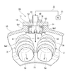
- FIG. 3 is a sectional view taken along line III-III in FIG. 2. It is sectional drawing of the buffer tank in 1st embodiment which concerns on this invention.
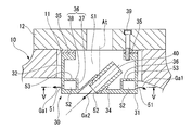
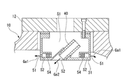
- FIG. 5 is a cross-sectional view taken along line VV in FIG. 4. It is sectional drawing of the buffer tank in the 1st modification of 1st embodiment which concerns on this invention. It is sectional drawing of the buffer tank in the 2nd modification of 1st embodiment which concerns on this invention. It is sectional drawing of the buffer tank in the 3rd modification of 1st embodiment which concerns on this invention.
- the gas turbine of the present embodiment includes a compressor 1 that compresses outside air to generate compressed air Gp, and a fuel from a fuel supply source mixed with the compressed air Gp and combusted to produce a combustion gas Gc.
- a compressor 1 that compresses outside air to generate compressed air Gp
- a fuel from a fuel supply source mixed with the compressed air Gp and combusted to produce a combustion gas Gc.
- combustors 2 and a turbine 3 driven by combustion gas Gc.
- the turbine 3 includes a rotor 4 that rotates about a rotor axis Ar, and a casing 8 that covers the rotor 4.
- a generator that generates electric power by rotation of the rotor 4 is connected to the rotor 4.
- the direction in which the rotor shaft Ar extends is referred to as an axial direction Da, and in this axial direction Da, the side where the compressor 1 is present with respect to the turbine 3 is the upstream side, and the opposite side is the downstream side.
- the circumferential direction with respect to the rotor shaft Ar is simply referred to as a circumferential direction Dc
- the radial direction with respect to the rotor shaft Ar is simply referred to as a radial direction Dr.
- the rotor 4 includes a rotor main body 5 extending in the axial direction Da around the rotor axis Ar, and a plurality of moving blades 6 attached to the rotor main body 5 side by side in the circumferential direction Dc.
- the rotor 4 has a plurality of rotor blade stages that are a collection of a plurality of rotor blades 6 arranged in the circumferential direction Dc.
- Each rotor blade stage is provided in the rotor body 5 side by side in the axial direction Da.
- a stationary blade stage is provided on the upstream side of each of the plurality of blade stages.
- Each stationary blade stage is composed of a plurality of stationary blades 7 arranged in the circumferential direction Dc.
- the plurality of combustors 2 are arranged in the circumferential direction Dc on the upstream side of the most upstream stationary blade stage. These combustors 2 are housed and fixed in a casing 10 that forms part of the casing 8.
- a manhole 11 is formed in the upper part of the passenger compartment 10, and the manhole 11 is closed by a manhole cover 12.
- the compressed air Gp generated by the compressor 1 flows into the passenger compartment 10 through the diffuser 1d.
- the compressed air Gp flows into the combustor 2 from the upstream side of the combustor 2.
- fuel is supplied to the combustor 2 from the fuel supply source. This fuel is mixed with the compressed air Gp in the combustor 2 and burned.
- the high-temperature and high-pressure combustion gas Gc generated by this combustion exits the combustor 2, it flows into the combustion gas passage 9 where the stationary blades 7 and the moving blades 6 exist, and rotates the rotor 4 in contact with the moving blades 6. .
- the diffuser 1 d of the compressor 1 is caused by the draft effect of the chimney exhaust structure provided further downstream of the turbine 3. A little air flows in from. This air flows into the combustion gas passage 9 via the combustor 2 in the same manner as the compressed air Gp described above.
- a region on the radially inner side of the upper combustor 2 among the plurality of combustors 2 arranged in the circumferential direction Dc and on the radially outer side of the diffuser 1d of the compressor 1 protruding into the casing 10 is: The stagnation part 19 with respect to this air flow is formed. In other words, the air in the stagnation portion 19 stagnates even if there is a slight flow of air in the passenger compartment 10 due to the draft effect when the turbine is stopped, and does not flow into the combustor 2 so much.
- the gas turbine of the present embodiment further includes a purge device 20 that ejects air into the passenger compartment 10.
- This purging device 20 buffers an air compressor 21 as an air supply source, a buffer tank 30 in which an air chamber into which air Ga from the air compressor 21 flows is formed, and air Ga from the air compressor 21. And an air line 22 for sending to the tank 30.
- the buffer tank 30 is fixed inside the passenger compartment 10 of the manhole cover 12. For this reason, most of the buffer tank 30 is accommodated in the manhole 11.
- the end of the air line 22 is connected to the manhole cover 12.
- the buffer tank 30 includes a cylindrical tank body 31, a partition wall 36 that partitions the tank body 31 into a first air chamber S1 and a second air chamber S2, and a nozzle 40 that ejects air Ga. Yes.
- the tank body 31 includes a cylindrical body 32, a bottom 34 that covers one end of the body 32, and an inner end from the other end of the body 32. And a flange portion 35 protruding to the circumferential side.
- the tank body 31 is fixed to the manhole cover 12 by a bolt 39 that penetrates the flange portion 35.
- the central axis of the cylindrical body 32 is referred to as a tank axis At.
- the partition wall 36 has a cylindrical wall 37 formed in a cylindrical shape around the tank axis At on the inner peripheral side of the trunk portion 32 of the tank body 31, and protrudes from one end of the cylindrical wall 37 to the outer peripheral side.
- Disc wall 38 The other end of the cylindrical wall 37 is fixed to the bottom 34 of the tank body 31. Further, the outer peripheral edge of the disk wall 38 is fixed to the body portion 32 of the tank body 31. Inside the tank body 31, between the cylindrical wall 37 of the partition wall 36 and the body part 32 of the tank body 31, and between the disk wall 38 of the partition wall 36 and the bottom part 34 of the tank body 31. The space forms the aforementioned second air chamber S2.
- the disc wall 38 (orifice plate) of the partition wall 36 is formed with a plurality of through holes 53 penetrating from the first air chamber S1 to the second air chamber S2. Further, a plurality of overall agitation air ports 51 are formed in the body portion 32 (entire agitation air ejection portion) to eject the air Ga in the second air chamber S2 into the passenger compartment 10 as the overall agitation air Ga1. ing.
- the nozzle 40 is detachably fixed to the bottom 34 of the tank body 31 so that one opening faces the vehicle interior 10 and the other opening faces the first air chamber S1 in the tank body 31.
- the nozzle 40 is inclined with respect to the radial direction Dr so that the aforementioned stagnation portion 19 is located on the extended line of the central axis, and adjacent to the circumferential direction Dc. It is fixed to the bottom 34 of the tank body 31 so as to face between the combustors 2. That is, the nozzle 40 is fixed to the tank body 31 so that the air Ga ejected from one opening is directed to the stagnation portion 19. Therefore, one opening of the nozzle 40 forms a stagnation part stirring air port 52 that ejects the air Ga in the first air chamber S1 as the stagnation part stirring air Ga2 toward the stagnation part 19.
- air Ga is injected from the purge device 20 into the vehicle compartment 10 to stir the air in the vehicle compartment 10.
- the air Ga from the air compressor 21 of the purge device 20 flows into the first air chamber S ⁇ b> 1 of the buffer tank 30 through the air line 22.
- Part of the air Ga that has flowed into the first air chamber S1 is ejected toward the stagnation part 19 as the stagnation part stirring air Ga2 from the stagnation part stirring air port 52 of the nozzle 40, and the stagnation part 19 is stirred. .
- the air Ga that has flowed into the second air chamber S2 is jetted into the vehicle compartment 10 from the plurality of overall agitation air ports 51 formed in the body portion 32 of the tank body 31 as the overall agitation air Ga1.
- the entire agitation air Ga1 is uniformly ejected from the cylindrical tank body 31 in the radial direction with respect to the tank axis At, flows along the upper inner wall surface of the passenger compartment 10, and substantially agitates the entire upper portion of the passenger compartment.
- the ejection speed of the gas depends on the pressure difference between the upstream side and the downstream side of the opening. That is, when the pressure on the downstream side of the opening is constant, the higher the pressure on the upstream side of the opening, the higher the ejection speed of the gas ejected from the opening, and the lower the pressure on the upstream side of the opening, The ejection speed of the gas ejected from the opening is reduced. For this reason, the second air whose pressure is lower than that in the first air chamber S1 with respect to the ejection speed when the air Ga in the first air chamber S1 is ejected from the stagnation part stirring air port 52 into the vehicle interior 10.
- the ejection speed when the air Ga in the chamber S2 is ejected from the entire agitation air port 51 into the vehicle compartment 10 is low. That is, the ejection speed of the overall stirring air Ga1 is relatively lower than the ejection speed of the stagnation part stirring air Ga2.
- the stagnation part 19 is located on the opposite side of the combustor 2 as viewed from the purge device 20 and is also far away. Therefore, in order to actively stir the stagnation part 19, the stagnation part stirring air Ga2 ejected from the stagnation part stirring air port 52 needs to go almost straight to the stagnation part 19, that is, the stagnation part stirring.
- the air Ga2 is required to be straight.
- the ejection speed of the stagnation part stirring air Ga2 is set to be relatively higher than the ejection speed of the overall stirring air Ga1, thereby improving the straightness of the stagnation part stirring air Ga2.
- the stagnation part 19 is actively stirred.
- the ejection speed of the overall stirring air Ga1 is made relatively low with respect to the ejection speed of the stagnation part stirring air Ga2, and the diffusibility of the overall stirring air Ga1 is increased, so that the stagnation part 19 The part which is not stirred in the upper part in the interior of the passenger compartment 10 except for is prevented.
- the air in the entire upper part of the passenger compartment 10 can be sufficiently agitated, and the temperature difference in each part in the passenger compartment 10 can be minimized. For this reason, in this embodiment, the deformation
- the present embodiment two types of air Ga1 and Ga2 having different jetting speeds are jetted into the passenger compartment 10, but only one type of air Ga needs to be supplied to the buffer tank 30.
- the compressor 21 and the air line 22 can be unified, and the manufacturing cost of the purge device 20 can be suppressed.
- the buffer tank 30 is provided in the passenger compartment 10, but most of the buffer tank 30 is accommodated in the manhole 11, so that the compression in the passenger compartment 10 during the operation of the gas turbine is performed. It hardly inhibits the flow of air Gp. Further, since the buffer tank 30 is attached to the manhole cover 12, the buffer tank 30 can be easily taken out of the vehicle compartment 10 by removing the manhole cover 12 from the vehicle compartment 10. For this reason, repair, change, etc. of the buffer tank 30 can be easily performed.
- the nozzle 40 which ejects the stagnation part stirring air Ga2 is detachably provided in the tank body 31 of the buffer tank 30, the stagnation part stirring can be performed by replacing the nozzle 40. It is possible to easily adjust the flow rate of the working air Ga2 and the ejection direction thereof.
- the nozzle 40 does not need to be detachable from the tank body 31 and may be formed integrally with the tank body 31.
- the through hole 53 is provided in the disk wall 38 of the partition wall 36 in the tank body 31, but the through hole 53 may be provided in the cylindrical wall 37 of the partition wall 36.
- the position of the through hole 53 of the cylindrical wall 37 and the position of the entire stirring air port 51 of the body portion 32 in the tank body 31 do not coincide with each other in the circumferential direction with respect to the tank axis At. . This is because the air Ga that has passed through the through-hole 53 of the cylindrical wall 37 advances straight, and a large amount of air Ga is ejected from the entire agitation air port 51 existing in the straight advance destination. This is to prevent air Ga from being ejected too much.
- an orifice 41 is provided in the nozzle 40, and other configurations are the same as those in the first embodiment.
- the ejection speed of the stagnation part stirring air Ga2 ejected from the nozzle 40 can be adjusted.
- the ejection speed of the stagnation part agitation air Ga2 needs to be higher than the ejection speed of the overall agitation air Ga1, so that the orifice 41 in the nozzle 40 and the stagnation part agitation air port 52
- the diameter of the through hole of the orifice 41 is determined so that the pressure between them is higher than the pressure in the second air chamber S2.
- a plurality of through holes 53 are formed in the disk wall 38 as an orifice plate in order to reduce the pressure of the air Ga before the air Ga in the first air chamber S1 reaches the entire stirring air port 51. is doing.
- a porous body 54 in which a large number of micropores are formed is provided as a pressure adjustment mechanism on the first air chamber S1 side with respect to the entire stirring air port 51.
- the overall stirring air Ga1 is the same as in the first embodiment. Can be made relatively lower than the ejection speed of the stagnation part stirring air Ga2.
- the pressure adjusting mechanism for reducing the pressure of the air Ga before the air Ga in the first air chamber S1 reaches the entire agitation air port 51 is not limited to the orifice, and provides resistance to the flow of the air Ga. As long as the pressure on the downstream side is reduced, any one may be used. For this reason, for example, a pipe having one end opened in the first air chamber S1 and the other end connected to the entire agitation air port 51 may be provided in the tank body 31 as a pressure adjusting mechanism. . In this case, since this pipe needs to have a larger pressure loss than the nozzle 40, its inner diameter is smaller than the inner diameter of the nozzle 40 and / or its length needs to be longer than the nozzle 40.
- a plurality of through holes 53 are formed in the disk wall 38 as an orifice plate in order to reduce the pressure of the air Ga before the air Ga in the first air chamber S1 reaches the entire stirring air port 51. is doing.
- a net structure 55 is provided in the entire stirring air port 51.
- the ejection speed of the overall stirring air Ga1 can be made relatively lower than the ejection speed of the stagnation part stirring air Ga2.
- This embodiment is mainly different from the first embodiment in the purge device. Therefore, in the following, the purge device 20a of the present embodiment will be mainly described in detail.
- the purge device 20a of the present embodiment ejects the air from the first air compressor 21a and the second air compressor 21b as air supply sources and the air from the first air compressor 21a into the passenger compartment 10 as the overall stirring air Ga1.
- the stagnation part agitation air jet pipe (stagnation part agitation air ejection part) 46 for ejecting the air from the two air compressor 21b into the passenger compartment 10 as the stagnation part agitation air Ga2, and the second air compressor 21b
- a stagnation part agitation air line 22b for sending air to the stagnation part agitation air jet pipe 46.
- the second air compressor 21b constitutes a stirrer stirring air supply source. Moreover, the 1st air compressor 21a comprises the air supply source for whole stirring, and supplies the air whose pressure is lower than the air Ga supplied from the 2nd air compressor 21b.
- the opening on the front end side of the stagnation part stirring air jet pipe 46 is opened in the passenger compartment 10 to form a stagnation part stirring air port 52. Further, the opening on the front end side of the entire agitation air ejection pipe 45 is also opened in the passenger compartment 10 to form the entire agitation air port 51.
- the stagnation part stirring air ejection pipe 46 is inclined with respect to the radial direction Dr and adjacent in the circumferential direction Dc so that the stagnation part 19 is located on the extended line of the central axis thereof, like the nozzle 40 of the first embodiment. It is being fixed to the upper part of the compartment 10 in the state which faces between the two combustors 2 which fit.
- the entire agitation air ejection pipe 45 is directed from the outside in the radial direction Dr toward the inside in the radial direction Dr, and is substantially perpendicular to the rotor axis Ar.
- the total agitation air ports 51 of the plurality of overall agitation air ejection pipes 45 are arranged in the circumferential direction Dc on the inner wall surface of the passenger compartment 10.
- the gas turbine of this embodiment includes an air bypass device 60 that supplies the compressed air Gp from the compressor 1 to the midstream portion of the combustor 2.
- the combustor 2 includes a tail cylinder 2b that sends high-temperature and high-pressure combustion gas Gc to the combustion gas flow path 9 of the turbine 3, and a fuel supplier 2a that supplies fuel and compressed air Gp into the tail cylinder 2b.
- the air bypass device 60 includes a bypass pipe 61 for supplying the compressed air Gp in the passenger compartment 10 into the tail cylinder 2 b of the combustor 2, and a grid valve 62 for adjusting the flow rate of the compressed air Gp flowing into the bypass pipe 61. And.
- the bypass pipe 61 is connected to each of the tail cylinders 2b of the plurality of combustors 2 arranged in the circumferential direction Dc.
- the grid valve 62 is a valve that adjusts the flow rate of the compressed air Gp flowing into each bypass pipe 61. Therefore, the grid valve 62 has an annular valve casing 63 centered on the rotor axis Ar, and a disc shape centered on the rotor axis Ar.
- the valve body moves in the circumferential direction Dc in contact with the valve casing 63. 65.
- an opening 64 is formed at a connection portion with each bypass pipe 61.
- valve body 65 on the disc plate is formed with the same number of openings 66 as the number of openings 64 of the valve casing 63.
- the flow rate of the valve body 65 relative to the valve casing 63 in the circumferential direction Dc is adjusted to flow into the bypass pipe 61 from the opening 66 of the valve body 65 through the opening 64 of the valve casing 63. .
- the plurality of overall agitation air ports 51 described above are arranged on the outer periphery side of the grit valve in the radial direction Dr.
- the air from the second air compressor 21b constituting the stagnation part agitation air supply source passes through the stagnation part agitation air line 22b and the stagnation part agitation air outlet pipe 46, and then stagnation part agitation part 52. It is ejected into the passenger compartment 10 as working air Ga2.
- the stagnation part stirring air Ga2 proceeds toward the stagnation part 19 and agitates the stagnation part 19.
- the air from the first air compressor 21a constituting the entire stirring air supply source passes through the entire stirring air line 22a and the entire stirring air jet pipe 45, and is then supplied from the entire stirring air port 51 to the entire stirring air. It is ejected into the passenger compartment 10 as Ga1.
- the overall agitation air Ga1 travels from the overall agitation air port 51 toward the inside in the radial direction Dr, and strikes and diffuses against the grid valve 62 disposed inside the overall agitation air port 51 in the radial direction Dr.
- the ejection speed of the stagnation part stirring air Ga2 is higher than the ejection speed of the overall stirring air Ga1. .
- the stagnation part stirring air Ga ⁇ b> 2 has high straightness and can stagnate the stagnation part 19 positively.
- the discharge pressure of the first air compressor 21a is lower than the discharge pressure of the second air compressor 21b
- the ejection speed of the overall stirring air Ga1 is lower than the ejection speed of the stagnation part stirring air Ga2.
- the whole stirring air Ga1 ejected from the whole stirring air port 51 strikes the grid valve 62 and further diffuses while diffusing.
- the overall stirring air Ga ⁇ b> 1 wraps around the inner peripheral side of the grid valve 62 because the speed hitting the grid valve 62 is relatively low.
- the entire upper part in the passenger compartment 10 can be sufficiently stirred, and deformation of the passenger compartment 10 when the gas turbine is stopped can be minimized.
- the vehicle compartment 10 Even when the grid valve 62 is not provided, if the entire stirring air Ga1 having a sufficient flow rate is supplied into the vehicle compartment 10 at a low speed, the vehicle compartment 10 does not cause local overcooling. It is possible to replace the high-temperature air staying in the upper part with the entire stirring-required air Ga1. Therefore, even when the grid valve 62 is not provided, the vehicle compartment 10 can be cooled while preventing local overcooling, and deformation of the vehicle compartment 10 can be suppressed.
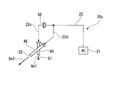
- the purge device 20c of the present modification includes an air compressor 21 as an air supply source, and a plurality of air for agitation that ejects a part of the air from the air compressor 21 into the vehicle compartment 10 as the air for agitation Ga1.
- the jet pipe 45, the stagnation part stirring air jet pipe 46 for jetting another part of the air into the passenger compartment 10 as the stagnation part stirring air Ga2, and the whole stirring air jet of the air from the air compressor 21 The main air line 23 for sending to the pipe 45 and the stagnation part stirring air jet pipe 46, and the whole stirring for sending air from the main air line 23 to the whole stirring air jet pipe 45.
- An air line 22c, a stagnation part agitation air line 22d that branches from the air main line 23 and sends the air from the air main line 23 to the stagnation part agitation air ejection pipe 46, and the entire agitation air line 22c are provided.
- the orifice 48 is provided as a pressure adjusting mechanism to reduce the pressure on the entire stirring air port 51 side with reference to the orifice 48.
- the ejection speed of the overall stirring air Ga1 ejected from the overall stirring air port 51 is equal to the stagnation portion ejected from the stagnation portion stirring air port 52. Lower than the ejection speed of the stirring air Ga2.
- the entire upper portion in the passenger compartment 10 can be sufficiently stirred, and deformation of the passenger compartment 10 when the gas turbine is stopped can be minimized.
- the orifice 48 is used as the pressure adjustment mechanism.
- the pressure adjustment mechanism is a resistance to the air flow, and the downstream side thereof. Any device that reduces the pressure may be used.
- the purge device 20d of this modification is a further modification of the first modification, and is provided with a net structure 55 in the entire agitation air port 51 instead of the orifice 48 in the first modification.
- This net structure 55 is the same as the net structure 55 shown in the third modification of the first embodiment, and a large number of openings having an area smaller than the opening area of the entire stirring air port 51 are formed. Yes.
- the ejection speed of the overall stirring air Ga1 can be made relatively lower than the ejection speed of the stagnation part stirring air Ga2, and the deformation of the casing 10 can be minimized when the gas turbine is stopped. Can be suppressed.
Landscapes
- Engineering & Computer Science (AREA)
- Mechanical Engineering (AREA)
- General Engineering & Computer Science (AREA)
- Chemical & Material Sciences (AREA)
- Combustion & Propulsion (AREA)
- Structures Of Non-Positive Displacement Pumps (AREA)
- Filling Or Discharging Of Gas Storage Vessels (AREA)
Description
本願は、2012年3月26日に、日本に出願された特願2012-069085号に基づき優先権を主張し、その内容をここに援用する。
すなわち、ガスタービンの停止時に、ガスタービンの車室内に空気を噴出して、該車室の変形を防止するパージ装置において、
前記空気を供給する空気供給源と、
前記車室内で気体の流れが淀む淀み部に向かって、前記空気の一部を淀み部撹拌用空気として噴出する淀み部撹拌用空気口が形成されている淀み部撹拌用空気噴出部と、
前記車室内で前記淀み部と異なる部位に向かって、前記空気の一部を全体撹拌用空気として噴出して、該車室内の上部空間に滞留する気体を攪拌する全体撹拌用空気口が形成されている全体撹拌用空気噴出部と、
前記全体撹拌用空気口からの前記全体撹拌用空気の噴出速度を前記淀み部撹拌用空気口からの前記淀み部撹拌用空気の噴出速度よりも低くする噴出速度調節手段と、を有することを特徴とする。
前記バッファタンクでは、前記空気供給源からの前記空気が流れ込む空気室がその内部に形成されていると共に、前記全体撹拌用空気口及び前記淀み部撹拌用空気口が形成されており、
前記噴出速度調節手段は、前記バッファタンクに設けられていてもよい。
前記パージ装置と、前記車室とを備えていることを特徴とする。
バッファタンクを有する前記パージ装置と前記車室とを備え、前記車室の上部には、マンホールが形成され、該マンホールは、マンホール蓋により塞がれており、前記バッファタンクは、前記マンホール蓋の前記車室内側に固定されていることを特徴とする。
ガスタービンへの燃料供給を停止するガスタービン停止ステップと、
車室内で気体の流れが淀む淀み部に向かって淀み部撹拌用空気を噴出して、該淀み部内の気体を撹拌すると共に、該車室内で該淀み部と異なる部位に向かって、該淀み部撹拌用空気の噴出速度よりも遅い噴出速度で全体撹拌用空気を噴出して、該車室内の上部空間に滞留する気体を攪拌する空気噴出ステップと、を含むことを特徴とする。
以下、本発明に係るガスタービンの第一実施形態について、図1~図5を参照して説明する。
ロータ4は、周方向Dcに並んでいる複数の動翼6の集まりである動翼段を複数有している。各動翼段は、軸方向Daに並んでロータ本体5に設けられている。ケーシング8の内周には、複数の動翼段毎の上流側に静翼段が設けられている。各静翼段は、周方向Dcに並ぶ複数の静翼7で構成されている。
圧縮機1で生成された圧縮空気Gpは、このディフューザ1dを通って車室10内に流れ込む。この圧縮空気Gpは、燃焼器2の上流側から燃焼器2内に流れ込む。燃焼器2には、前述したように燃料供給源から燃料が供給される。この燃料は、燃焼器2内で圧縮空気Gpと混合されて燃焼する。この燃焼により生成された高温高圧の燃焼ガスGcは、燃焼器2から出ると、静翼7及び動翼6が存在する燃焼ガス流路9に流れ込み、動翼6に接してロータ4を回転させる。
次に、第一実施形態の第一変形例について、図6を参照して説明する。
次に、第一実施形態の第二変形例について、図7を参照して説明する。
次に、第一実施形態の第三変形例について、図8を参照して説明する。
次に、本発明に係るガスタービンの第二実施形態について、図9を参照して説明する。
グリッド弁62は、弁ケーシング63に対して弁体65が周方向Dcに相対移動することで、弁体65の開口66から弁ケーシング63の開口64を経てバイパス配管61に流れ込む流量が調節される。
次に、第二実施形態の第一変形例について、図10を参照して説明する。
次に、第二実施形態の第二変形例について、図11を参照して説明する。
Claims (10)
- ガスタービンの停止時に、ガスタービンの車室内に空気を噴出して、該車室の変形を防止するパージ装置であって、
前記空気を供給する空気供給源と、
前記車室内で気体の流れが淀む淀み部に向かって、前記空気の一部を淀み部撹拌用空気として噴出する淀み部撹拌用空気口が形成されている淀み部撹拌用空気噴出部と、
前記車室内で前記淀み部と異なる部位に向かって、前記空気の一部を全体撹拌用空気として噴出して、該車室内の上部空間に滞留する気体を攪拌する全体撹拌用空気口が形成されている全体撹拌用空気噴出部と、
前記全体撹拌用空気口からの前記全体撹拌用空気の噴出速度を前記淀み部撹拌用空気口からの前記淀み部撹拌用空気の噴出速度よりも低くする噴出速度調節手段と、
を有することを特徴とするパージ装置。 - 請求項1に記載のパージ装置であって、
前記噴出速度調節手段は、前記空気供給源からの前記空気が前記全体撹拌用空気口に至る手前の圧力を、前記空気供給源からの前記空気が前記淀み部撹拌用空気口に至る手前の圧力よりも低くする圧力調節機構を有する、パージ装置。 - 請求項2に記載のパージ装置であって、
前記圧力調節機構は、前記全体撹拌用空気口の手前に配置され、前記空気供給源からの前記空気が通る貫通孔が形成されているオリフィスを有する、パージ装置。 - 請求項1に記載のパージ装置であって、
前記噴出速度調節手段は、前記全体撹拌用空気口に設けられ、該全体撹拌用空気口の開口面積よりも小さな面積の多数の開口が形成されている網構造体を有する、パージ装置。 - 請求項1から4のいずれか一項に記載のパージ装置であって、
バッファタンクを有し、
前記バッファタンクでは、前記空気供給源からの前記空気が流れ込む空気室が内部に形成されていると共に、前記全体撹拌用空気口及び前記淀み部撹拌用空気口が形成されており、
前記噴出速度調節手段は、前記バッファタンクに設けられている、パージ装置。 - 請求項1から4のいずれか一項に記載のパージ装置であって、
前記空気供給源からの空気が通る主ラインと、該主ラインから分岐して前記全体撹拌用空気口と連通している全体撹拌用空気ラインと、該主ラインから分岐して前記淀み部撹拌用空気口と連通している淀み部撹拌用空気ラインと、を有し、
前記圧力調節機構は、前記全体撹拌用空気ラインに設けられている、パージ装置。 - 請求項1に記載のパージ装置であって、
前記空気供給源は、前記淀み部撹拌用空気となる前記空気を前記淀み部撹拌用空気口に供給する淀み部撹拌用空気供給源と、前記全体撹拌用空気となる前記空気であって、該淀み部撹拌用空気供給源から供給される前記空気よりも圧力の低い空気を前記全体撹拌用空気口に供給する全体撹拌用空気供給源と、を有している、パージ装置。 - 請求項1から7のいずれか一項に記載のパージ装置と、前記車室とを備えている、ことを特徴とするガスタービン。
- 請求項5に記載のパージ装置と、前記車室とを備え、
前記車室の上部には、マンホールが形成され、該マンホールは、マンホール蓋により塞がれており、
前記バッファタンクは、前記マンホール蓋の前記車室内側に固定されている、ことを特徴とするガスタービン。 - ガスタービンの車室の変形を防止する方法であって、
前記ガスタービンへの燃料供給を停止するガスタービン停止ステップと、
前記車室内で気体の流れが淀む淀み部に向かって淀み部撹拌用空気を噴出して、該淀み部内の気体を撹拌すると共に、該車室内で該淀み部と異なる部位に向かって、該淀み部撹拌用空気の噴出速度よりも遅い噴出速度で全体撹拌用空気を噴出して、該車室内の上部空間に滞留する気体を攪拌する空気噴出ステップと、
を含む、ことを特徴とする車室の変形を防止する方法。
Priority Applications (3)
| Application Number | Priority Date | Filing Date | Title |
|---|---|---|---|
| DE112012006100.4T DE112012006100B4 (de) | 2012-03-26 | 2012-11-01 | Verfahren zur Verhinderung einer Verformung in einem Gasturbinengehäuse, Spülvorrichtung zur Ausführung dieses Verfahrens und mit dieser Vorrichtung versehene Gasturbine |
| KR1020147021144A KR101593862B1 (ko) | 2012-03-26 | 2012-11-01 | 가스 터빈의 차실의 변형을 방지하는 방법, 이것을 실행하는 퍼지 장치, 및 이 장치를 구비하고 있는 가스 터빈 |
| CN201280071674.XA CN104204466B (zh) | 2012-03-26 | 2012-11-01 | 防止燃气轮机的机室变形的方法、执行该方法的吹扫装置和具备该装置的燃气轮机 |
Applications Claiming Priority (2)
| Application Number | Priority Date | Filing Date | Title |
|---|---|---|---|
| JP2012-069085 | 2012-03-26 | ||
| JP2012069085A JP5984447B2 (ja) | 2012-03-26 | 2012-03-26 | ガスタービンの車室の変形を防止する方法、これを実行するパージ装置、及びこの装置を備えているガスタービン |
Publications (1)
| Publication Number | Publication Date |
|---|---|
| WO2013145402A1 true WO2013145402A1 (ja) | 2013-10-03 |
Family
ID=49211949
Family Applications (1)
| Application Number | Title | Priority Date | Filing Date |
|---|---|---|---|
| PCT/JP2012/078376 Ceased WO2013145402A1 (ja) | 2012-03-26 | 2012-11-01 | ガスタービンの車室の変形を防止する方法、これを実行するパージ装置、及びこの装置を備えているガスタービン |
Country Status (6)
| Country | Link |
|---|---|
| US (1) | US9624788B2 (ja) |
| JP (1) | JP5984447B2 (ja) |
| KR (1) | KR101593862B1 (ja) |
| CN (1) | CN104204466B (ja) |
| DE (1) | DE112012006100B4 (ja) |
| WO (1) | WO2013145402A1 (ja) |
Cited By (1)
| Publication number | Priority date | Publication date | Assignee | Title |
|---|---|---|---|---|
| WO2014176085A1 (en) * | 2013-04-26 | 2014-10-30 | Siemens Aktiengesellschaft | Turbine engine shutdown temperature control system |
Families Citing this family (25)
| Publication number | Priority date | Publication date | Assignee | Title |
|---|---|---|---|---|
| WO2015036233A1 (de) * | 2013-09-10 | 2015-03-19 | Siemens Aktiengesellschaft | Kühlluftleitung zur entnahme von kühlluft aus einem mannloch einer gasturbine |
| US10443507B2 (en) | 2016-02-12 | 2019-10-15 | United Technologies Corporation | Gas turbine engine bowed rotor avoidance system |
| US9664070B1 (en) | 2016-02-12 | 2017-05-30 | United Technologies Corporation | Bowed rotor prevention system |
| US10125691B2 (en) | 2016-02-12 | 2018-11-13 | United Technologies Corporation | Bowed rotor start using a variable position starter valve |
| US10040577B2 (en) | 2016-02-12 | 2018-08-07 | United Technologies Corporation | Modified start sequence of a gas turbine engine |
| US10539079B2 (en) | 2016-02-12 | 2020-01-21 | United Technologies Corporation | Bowed rotor start mitigation in a gas turbine engine using aircraft-derived parameters |
| US10174678B2 (en) | 2016-02-12 | 2019-01-08 | United Technologies Corporation | Bowed rotor start using direct temperature measurement |
| US10508601B2 (en) | 2016-02-12 | 2019-12-17 | United Technologies Corporation | Auxiliary drive bowed rotor prevention system for a gas turbine engine |
| US10125636B2 (en) | 2016-02-12 | 2018-11-13 | United Technologies Corporation | Bowed rotor prevention system using waste heat |
| US10508567B2 (en) | 2016-02-12 | 2019-12-17 | United Technologies Corporation | Auxiliary drive bowed rotor prevention system for a gas turbine engine through an engine accessory |
| US10443505B2 (en) | 2016-02-12 | 2019-10-15 | United Technologies Corporation | Bowed rotor start mitigation in a gas turbine engine |
| US10436064B2 (en) | 2016-02-12 | 2019-10-08 | United Technologies Corporation | Bowed rotor start response damping system |
| US10598047B2 (en) | 2016-02-29 | 2020-03-24 | United Technologies Corporation | Low-power bowed rotor prevention system |
| US10787933B2 (en) | 2016-06-20 | 2020-09-29 | Raytheon Technologies Corporation | Low-power bowed rotor prevention and monitoring system |
| US10358936B2 (en) | 2016-07-05 | 2019-07-23 | United Technologies Corporation | Bowed rotor sensor system |
| EP3273006B1 (en) | 2016-07-21 | 2019-07-03 | United Technologies Corporation | Alternating starter use during multi-engine motoring |
| US10618666B2 (en) | 2016-07-21 | 2020-04-14 | United Technologies Corporation | Pre-start motoring synchronization for multiple engines |
| US10221774B2 (en) | 2016-07-21 | 2019-03-05 | United Technologies Corporation | Speed control during motoring of a gas turbine engine |
| US10384791B2 (en) | 2016-07-21 | 2019-08-20 | United Technologies Corporation | Cross engine coordination during gas turbine engine motoring |
| EP3273016B1 (en) | 2016-07-21 | 2020-04-01 | United Technologies Corporation | Multi-engine coordination during gas turbine engine motoring |
| US10787968B2 (en) | 2016-09-30 | 2020-09-29 | Raytheon Technologies Corporation | Gas turbine engine motoring with starter air valve manual override |
| US10443543B2 (en) | 2016-11-04 | 2019-10-15 | United Technologies Corporation | High compressor build clearance reduction |
| US10823079B2 (en) | 2016-11-29 | 2020-11-03 | Raytheon Technologies Corporation | Metered orifice for motoring of a gas turbine engine |
| JP6651665B1 (ja) | 2019-03-28 | 2020-02-19 | 三菱日立パワーシステムズ株式会社 | タービン車室、ガスタービン及びタービン車室の変形防止方法 |
| EP4127434A4 (en) * | 2020-04-03 | 2024-04-17 | Technion Research & Development Foundation Ltd. | ADDITIVELY MANUFACTURED GAS TURBINE ENGINE AND FAN |
Citations (4)
| Publication number | Priority date | Publication date | Assignee | Title |
|---|---|---|---|---|
| JPH0626364A (ja) * | 1992-07-08 | 1994-02-01 | Mitsubishi Heavy Ind Ltd | ガスタービンケーシングの変形防止装置 |
| JPH1082322A (ja) * | 1996-09-06 | 1998-03-31 | Kubota Corp | ディーゼルエンジンの副室式燃焼室 |
| JP2006037855A (ja) * | 2004-07-28 | 2006-02-09 | Mitsubishi Heavy Ind Ltd | 車室ケーシング及びガスタービン |
| JP2006342784A (ja) * | 2005-06-10 | 2006-12-21 | Mitsubishi Heavy Ind Ltd | ガスタービン及び空気供給制御方法、並びに空気供給制御用コンピュータプログラム |
Family Cites Families (10)
| Publication number | Priority date | Publication date | Assignee | Title |
|---|---|---|---|---|
| US6065282A (en) * | 1997-10-29 | 2000-05-23 | Mitsubishi Heavy Industries, Ltd. | System for cooling blades in a gas turbine |
| JP2003254010A (ja) | 2002-03-01 | 2003-09-10 | Mitsubishi Heavy Ind Ltd | 蒸気タービン車室 |
| JP4015560B2 (ja) * | 2003-01-16 | 2007-11-28 | 三菱重工業株式会社 | デュアル焚きガスタービンの運転方法 |
| JP2005171795A (ja) * | 2003-12-09 | 2005-06-30 | Mitsubishi Heavy Ind Ltd | ガスタービン燃焼装置 |
| US7987660B2 (en) * | 2005-06-10 | 2011-08-02 | Mitsubishi Heavy Industries, Ltd. | Gas turbine, method of controlling air supply and computer program product for controlling air supply |
| JP4523876B2 (ja) | 2005-06-10 | 2010-08-11 | 三菱重工業株式会社 | ガスタービン及び空気供給制御方法、並びに空気供給制御用コンピュータプログラム |
| US7708518B2 (en) * | 2005-06-23 | 2010-05-04 | Siemens Energy, Inc. | Turbine blade tip clearance control |
| US20070271930A1 (en) * | 2006-05-03 | 2007-11-29 | Mitsubishi Heavy Industries, Ltd. | Gas turbine having cooling-air transfer system |
| EP2249003B1 (en) * | 2008-02-27 | 2016-11-02 | Mitsubishi Hitachi Power Systems, Ltd. | Gas turbine |
| US8973372B2 (en) * | 2012-09-05 | 2015-03-10 | Siemens Aktiengesellschaft | Combustor shell air recirculation system in a gas turbine engine |
-
2012
- 2012-03-26 JP JP2012069085A patent/JP5984447B2/ja active Active
- 2012-11-01 WO PCT/JP2012/078376 patent/WO2013145402A1/ja not_active Ceased
- 2012-11-01 KR KR1020147021144A patent/KR101593862B1/ko active Active
- 2012-11-01 CN CN201280071674.XA patent/CN104204466B/zh active Active
- 2012-11-01 DE DE112012006100.4T patent/DE112012006100B4/de active Active
- 2012-11-02 US US13/667,379 patent/US9624788B2/en active Active
Patent Citations (4)
| Publication number | Priority date | Publication date | Assignee | Title |
|---|---|---|---|---|
| JPH0626364A (ja) * | 1992-07-08 | 1994-02-01 | Mitsubishi Heavy Ind Ltd | ガスタービンケーシングの変形防止装置 |
| JPH1082322A (ja) * | 1996-09-06 | 1998-03-31 | Kubota Corp | ディーゼルエンジンの副室式燃焼室 |
| JP2006037855A (ja) * | 2004-07-28 | 2006-02-09 | Mitsubishi Heavy Ind Ltd | 車室ケーシング及びガスタービン |
| JP2006342784A (ja) * | 2005-06-10 | 2006-12-21 | Mitsubishi Heavy Ind Ltd | ガスタービン及び空気供給制御方法、並びに空気供給制御用コンピュータプログラム |
Cited By (1)
| Publication number | Priority date | Publication date | Assignee | Title |
|---|---|---|---|---|
| WO2014176085A1 (en) * | 2013-04-26 | 2014-10-30 | Siemens Aktiengesellschaft | Turbine engine shutdown temperature control system |
Also Published As
| Publication number | Publication date |
|---|---|
| US9624788B2 (en) | 2017-04-18 |
| CN104204466A (zh) | 2014-12-10 |
| DE112012006100T5 (de) | 2015-01-08 |
| KR101593862B1 (ko) | 2016-02-12 |
| DE112012006100B4 (de) | 2024-03-21 |
| JP2013199892A (ja) | 2013-10-03 |
| KR20140108325A (ko) | 2014-09-05 |
| JP5984447B2 (ja) | 2016-09-06 |
| US20130251501A1 (en) | 2013-09-26 |
| CN104204466B (zh) | 2017-03-08 |
Similar Documents
| Publication | Publication Date | Title |
|---|---|---|
| JP5984447B2 (ja) | ガスタービンの車室の変形を防止する方法、これを実行するパージ装置、及びこの装置を備えているガスタービン | |
| JP6976051B2 (ja) | ガスタービンの燃焼システムにおける段階的な燃料および空気噴射 | |
| JP5178207B2 (ja) | 翼形、スリーブ及び燃焼器アセンブリの組立方法 | |
| RU2457400C2 (ru) | Камера сгорания для газотурбинного двигателя | |
| JP5057821B2 (ja) | 空気と燃料の混合物を噴射する装置、両方ともそのような装置を装備した燃焼チャンバおよびターボ機械 | |
| JP4709433B2 (ja) | ガスタービン燃焼器 | |
| JP6138584B2 (ja) | タービンエンジンに使用するための燃料注入組立体及びそれを組み立てる方法 | |
| US9803501B2 (en) | Engine mid-turbine frame distributive coolant flow | |
| KR101817460B1 (ko) | 가스 터빈 | |
| JP2010077868A (ja) | ガスタービンのリムシール構造 | |
| US20160377290A1 (en) | Gas turbine combustor | |
| JP2010175243A (ja) | ターボ機械における燃焼ダイナミックスを低減するためのシステム及び方法 | |
| JP2010077869A (ja) | ガスタービンのリムシール構造 | |
| KR102225831B1 (ko) | 연소기 및 그 연소기를 구비하는 가스 터빈 | |
| JP2016521329A (ja) | ターボ機械の吸気口ケーシングを洗浄する装置 | |
| JP6001854B2 (ja) | タービンエンジン用燃焼器組立体及びその組み立て方法 | |
| US20100024425A1 (en) | Turbine engine fuel nozzle | |
| JP2013181744A (ja) | タービンエンジンで使用するための燃料ノズルアセンブリおよびそれを組み立てる方法 | |
| JP2012047173A (ja) | ガスタービンエンジンにおける燃焼器冷却及び運転に関連するシステム及び装置 | |
| JP5495893B2 (ja) | ガスタービンおよびその改造方法 | |
| US11293347B2 (en) | Airfoil with baffle showerhead and cooling passage network having aft inlet | |
| US10443401B2 (en) | Cooled turbine vane with alternately orientated film cooling hole rows | |
| JP4031774B2 (ja) | ガスタービン用燃焼器 | |
| JP2024119224A (ja) | 燃焼器用筒体、燃焼器及びガスタービン | |
| JP4495198B2 (ja) | ガスタービン用燃焼器 |
Legal Events
| Date | Code | Title | Description |
|---|---|---|---|
| 121 | Ep: the epo has been informed by wipo that ep was designated in this application |
Ref document number: 12872691 Country of ref document: EP Kind code of ref document: A1 |
|
| ENP | Entry into the national phase |
Ref document number: 20147021144 Country of ref document: KR Kind code of ref document: A |
|
| WWE | Wipo information: entry into national phase |
Ref document number: 112012006100 Country of ref document: DE Ref document number: 1120120061004 Country of ref document: DE |
|
| 122 | Ep: pct application non-entry in european phase |
Ref document number: 12872691 Country of ref document: EP Kind code of ref document: A1 |