WO2013145206A1 - 電力変換システム - Google Patents
電力変換システム Download PDFInfo
- Publication number
- WO2013145206A1 WO2013145206A1 PCT/JP2012/058346 JP2012058346W WO2013145206A1 WO 2013145206 A1 WO2013145206 A1 WO 2013145206A1 JP 2012058346 W JP2012058346 W JP 2012058346W WO 2013145206 A1 WO2013145206 A1 WO 2013145206A1
- Authority
- WO
- WIPO (PCT)
- Prior art keywords
- power
- amount
- ratio
- conversion system
- supplied
- Prior art date
- Legal status (The legal status is an assumption and is not a legal conclusion. Google has not performed a legal analysis and makes no representation as to the accuracy of the status listed.)
- Ceased
Links
Images

Classifications
-
- H—ELECTRICITY
- H02—GENERATION; CONVERSION OR DISTRIBUTION OF ELECTRIC POWER
- H02J—ELECTRIC POWER NETWORKS; CIRCUIT ARRANGEMENTS OR SYSTEMS FOR SUPPLYING OR DISTRIBUTING ELECTRIC POWER; SYSTEMS FOR STORING ELECTRIC ENERGY
- H02J3/00—Circuit arrangements for AC mains or AC distribution networks
- H02J3/38—Arrangements for feeding a single network from two or more generators or sources in parallel; Arrangements for feeding already energised networks from additional generators or sources in parallel
- H02J3/381—Dispersed generators
-
- H—ELECTRICITY
- H02—GENERATION; CONVERSION OR DISTRIBUTION OF ELECTRIC POWER
- H02J—ELECTRIC POWER NETWORKS; CIRCUIT ARRANGEMENTS OR SYSTEMS FOR SUPPLYING OR DISTRIBUTING ELECTRIC POWER; SYSTEMS FOR STORING ELECTRIC ENERGY
- H02J3/00—Circuit arrangements for AC mains or AC distribution networks
- H02J3/38—Arrangements for feeding a single network from two or more generators or sources in parallel; Arrangements for feeding already energised networks from additional generators or sources in parallel
- H02J3/40—Synchronisation of generators for connection to a network or to another generator
-
- H—ELECTRICITY
- H02—GENERATION; CONVERSION OR DISTRIBUTION OF ELECTRIC POWER
- H02J—ELECTRIC POWER NETWORKS; CIRCUIT ARRANGEMENTS OR SYSTEMS FOR SUPPLYING OR DISTRIBUTING ELECTRIC POWER; SYSTEMS FOR STORING ELECTRIC ENERGY
- H02J2101/00—Supply or distribution of decentralised, dispersed or local electric power generation
- H02J2101/20—Dispersed power generation using renewable energy sources
- H02J2101/22—Solar energy
- H02J2101/24—Photovoltaics
-
- Y—GENERAL TAGGING OF NEW TECHNOLOGICAL DEVELOPMENTS; GENERAL TAGGING OF CROSS-SECTIONAL TECHNOLOGIES SPANNING OVER SEVERAL SECTIONS OF THE IPC; TECHNICAL SUBJECTS COVERED BY FORMER USPC CROSS-REFERENCE ART COLLECTIONS [XRACs] AND DIGESTS
- Y02—TECHNOLOGIES OR APPLICATIONS FOR MITIGATION OR ADAPTATION AGAINST CLIMATE CHANGE
- Y02B—CLIMATE CHANGE MITIGATION TECHNOLOGIES RELATED TO BUILDINGS, e.g. HOUSING, HOUSE APPLIANCES OR RELATED END-USER APPLICATIONS
- Y02B10/00—Integration of renewable energy sources in buildings
- Y02B10/10—Photovoltaic [PV]
-
- Y—GENERAL TAGGING OF NEW TECHNOLOGICAL DEVELOPMENTS; GENERAL TAGGING OF CROSS-SECTIONAL TECHNOLOGIES SPANNING OVER SEVERAL SECTIONS OF THE IPC; TECHNICAL SUBJECTS COVERED BY FORMER USPC CROSS-REFERENCE ART COLLECTIONS [XRACs] AND DIGESTS
- Y02—TECHNOLOGIES OR APPLICATIONS FOR MITIGATION OR ADAPTATION AGAINST CLIMATE CHANGE
- Y02E—REDUCTION OF GREENHOUSE GAS [GHG] EMISSIONS, RELATED TO ENERGY GENERATION, TRANSMISSION OR DISTRIBUTION
- Y02E10/00—Energy generation through renewable energy sources
- Y02E10/50—Photovoltaic [PV] energy
- Y02E10/56—Power conversion systems, e.g. maximum power point trackers
Definitions
- the present invention relates to a power conversion system that converts power generated by a generator into AC power and supplies the AC power to a plurality of consumers.
- Patent Document 1 a power conversion system that distributes generated power of a common generator (for example, a solar cell, a fuel cell, a wind power generator, etc.) to a plurality of consumers at a predetermined distribution ratio.
- a common generator for example, a solar cell, a fuel cell, a wind power generator, etc.
- Such a power conversion system is, for example, a distribution that is determined in advance according to the investment ratio or the like when it is desired to provide a common generator in an apartment house, or when a plurality of neighboring customers want to provide a common generator. The generator was used using the ratio.
- This power conversion system includes a solar cell as a generator, and converts the generated power of the solar cell into AC power by an inverter circuit.
- the converted AC power is distributed to each consumer using a branch wiring that branches from the output side of the inverter circuit.
- Each branch line connected to each consumer is provided with a power controller, and when distributing power, the power controller controls on / off of the power flowing through the branch line to each customer.
- the power of the above-described distribution ratio is distributed.
- the present invention has been made in view of the above-described problems, and an object thereof is to provide a power conversion system that can suppress unfairness due to power distribution while configuring the system at a low cost.
- the present invention includes an inverter circuit that converts DC power into AC power and a branch wiring that branches off the output side of the inverter circuit, and provides a plurality of consumers who receive power supply from a commercial power system.
- the power conversion system includes a power detection circuit that detects a supply power amount for a predetermined period supplied to each branch line connected to the consumer, When the ratio of the amount of power to be distributed to the branch wiring is configured to be settable, and the ratio of the amount of supplied power detected by the power detection circuit is different from the ratio of the amount of power to be distributed to the branch wiring, each demand A power conversion system characterized by notifying a house of an excessive or insufficient amount of power.
- power is distributed to each consumer using branch wiring, and AC power is supplied to a plurality of consumers using an inexpensive configuration sharing an inverter circuit. Moreover, since each consumer can grasp
- the amount of sold power that flows backward from each consumer to the commercial power system is detected, and consumed by each of the supplied power based on the supplied power amount and the sold power amount. 2.
- the unit price of the commercial power grid and the unit price of the commercial power grid are input, and the power consumption is calculated using the unit price of the power grid.
- An excess or deficiency of electricity charges is informed by the ratio, and the electricity sales amount is informed of an excess or deficiency of electricity charges by the ratio using the unit price of the power sale charges.
- the unit price of the electricity charge for the excess or deficient electric energy can be set, and the ratio of the electric energy supplied to each customer detected by the electric power detection circuit is distributed to the branch wiring. If it is different from the ratio of the amount of electric power to be used, it is characterized by notifying each consumer of the electric charge of the electric power amount that is excessive or insufficient using the set unit price of the electric charge.
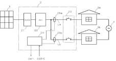
- FIG. 1 is a schematic diagram showing a power conversion system 2. As shown in this figure, each consumer 3a, 3b is supplied with AC power from the commercial power system 4, and a common power conversion system 2 is provided for these consumers 3a, 3b.
- a common solar cell 1 (generator) is connected to the consumers 3a and 3b.
- the consumers 3a and 3b are constituted by detached houses, and the consumers 3a and 3b are neighboring houses, respectively. For example, it is installed in the consumer 3a.
- the solar cell 1 is disposed on the roof of the consumer 3a, and the power conversion system 2 is disposed beside the first floor (the consumer 3a) of the building.
- the generated power of the solar cell 1 is input to the power conversion system 2, and the power conversion system 2 distributes and supplies this generated power to the respective consumers 3a and 3b.
- the consumers 3a and 3b are not limited to neighboring single-family houses, and may be constituted by apartment houses such as apartments and apartments.
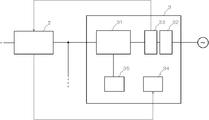
- FIG. 2 is a schematic diagram showing a consumer. Since the customers 3a and 3b have the same configuration, they will be described as the customer 3. As shown in this figure, the customer 3 has a distribution board 31.
- the distribution board 31 inputs AC power supplied from the commercial power system 4 and AC power supplied from the power conversion system. The input power is superimposed and supplied to the load 35 of the consumer 3. .
- a power purchase meter 32 and a power sale meter 33 are provided on the commercial power system 4 side of the distribution board 31 of each customer 3, respectively.
- the electricity purchase meter 32 detects the amount of power supplied from the commercial power system 4 to the consumer 3.
- the detected amount of electric power (the amount of electric power purchased) is used to calculate the electric power purchased electric charge.
- the electricity sales meter 33 detects the amount of electric power supplied from the consumers 3a, 3b to the commercial power system 4.
- the detected power amount (power sale power amount) is used to calculate a power sale power charge.
- each consumer 3a, 3b is individually provided with a distribution board 32 and a power sale meter 33, and is configured to be able to individually buy and sell power with an electric power company.
- each of the consumers 2a and 2b is provided with a display monitor 34 so that the usage status of the power of the consumers 2a and 2b can be displayed.
- the power conversion system 2 includes a booster circuit 21, an inverter circuit 22, an interconnection relay 23 (switch), a control circuit 24, and output current sensors 25a and 25b. Further, the booster circuit 21, the inverter circuit 22, the interconnection relay 23, the control circuit 24, the input current sensor 51, and the output current sensors 25a and 25b are housed in a common housing, and a common housing is provided by arranging this housing. It is put together in the place (here the customer 2c).
- the booster circuit 21 is connected between the solar cell 1 and the inverter circuit 22 and boosts the voltage of the solar cell 1.
- the booster circuit 21 includes a reactor, a switching element such as IGBT or FET, a diode circuit, and a capacitor. Specifically, the reactor and the diode are connected in series to form a series circuit, and the reactor side of the series circuit is connected to the positive electrode side of the solar cell 1. Moreover, the connection point of a reactor and a diode and the negative electrode side of a solar cell are connected via the switch element. Moreover, the diode side of the series circuit and the negative electrode side of the solar cell are connected via a capacitor.
- the booster circuit 21 periodically conducts / cuts off the switch element. For example, by setting a ratio (hereinafter referred to as ON ratio) for conducting the switch element for each period, the voltage of the solar cell is set at a desired boost ratio. Boost and output to both ends of the capacitor.
- ON ratio hereinafter referred to as ON ratio
- the inverter circuit 22 converts the power generated by the solar cell 3 input via the booster circuit 21 into AC power. Further, branch lines La and Lb branching from the output side of the inverter circuit 22 are connected to the output side of the inverter circuit 12, and the respective consumers 3a and 3b are connected to the respective consumers 3a and 3b via the branch lines. Distributes the AC power to be output.
- the inverter circuit 22 has a bridge circuit composed of four switch elements such as IGBT and FET, and a filter circuit composed of two reactors and a capacitor.
- the DC side is connected to both ends of the capacitor of the booster circuit, and the AC side is connected to the filter circuit.
- the filter circuit one end of each of the two reactors is connected by a capacitor, and the other end of each of the reactors is connected to the AC side of the bridge circuit.
- the inverter circuit 22 uses a predetermined PWM (Pulse Width Modulation) signal to generate and supply AC power having a waveform synchronized with the commercial power system to the consumers 3a and 3b by turning on and off the four switch elements. To do.
- PWM Pulse Width Modulation
- the interconnection relay 23 is interposed in the branch lines La and Lb, respectively, and connects / releases the lines of the branch lines La and Lb. As a result, when the interconnection relay 23 is connected, the AC power output from the inverter circuit 22 is supplied to the consumers 2a and 2b, and when the interconnection relay 23 is opened, the consumers 3a and 3b are supplied. The AC power output from the supplied inverter circuit 22 is cut off.
- the branch wirings La and Lb are provided with output current sensors 53a and 53b, respectively, and detect instantaneous output currents Ioa and Iob of the branch wirings La and Lb, respectively.
- the detected output currents Ioa and Iob are input to the control circuit, and the execution values (or average values) are output in the control circuit 14 using the output currents Ioa and Iob and the output voltages Voa and Vob input in the past. Calculated.
- the effective values of the output currents Ioa and Iob are referred to as output currents Ia and Ib.
- the output currents Ia and Ib are used for controlling the operation of the power conversion system 11 and the like.
- the control circuit 24 is composed of, for example, a microcomputer, and controls the operation of the booster circuit 21, the operation of the inverter circuit 22, and the operation of the interconnection relay 23.
- the control circuit 24 controls the ON ratio of the booster circuit 21 so that the generated power of the solar cell 1 (input power to the booster circuit 21) is maximized.
- the generated power of the solar cell 1 input to the booster circuit 21 is calculated from the input current and the input voltage obtained from the input current sensor 51 and the input voltage sensor 52. If the calculated generated power is greater than the previously calculated generated power, change the ON ratio to the same one that changed the previous ON ratio (lower the previous ON ratio, lower it again, and increase the previous ON ratio) If you do, increase it). Conversely, if the generated power is smaller than the previously calculated power, change the ON ratio to the opposite of the previous ON ratio change (the higher the previous ON ratio, the higher the previous ON ratio) If so, lower).
- the control circuit 24 generates a PWM signal for turning on / off the switch element of the inverter circuit 22. Specifically, the control circuit 24 calculates the output current command value It of the inverter circuit 12 and simplifies the description by assuming that the commercial system voltage supplied to each consumer is the same, and detects the detected output current ( A PWM signal that outputs the output voltage of the inverter circuit 22 is generated so that Ia + Ib) matches the output current command value.
- the control circuit 24 generates a signal for connecting / releasing the interconnection relay 23 and controls the interconnection relay 23 to be in a desired state (connection state or open state). For example, when the solar cell 1 becomes capable of generating power, the interconnection relay 23 is set in a connected state, and when the solar cell 1 becomes incapable of generating power, the interconnection relay 23 is opened. The solar cell 1 and the commercial power system are separated.
- the control circuit 24 receives and stores the ratio of the amount of power to be distributed to the plurality of branch lines La and Lb by an input unit (not shown). Based on the output currents Ia and Ib detected by the output current sensors 25a and 25b, the control circuit 24 supplies power for a predetermined period supplied to the branch wirings La and Lb connected to the consumers 3a and 3b. Is detected. That is, the control circuit 24 functions as a power detection circuit that detects the amount of power supplied from the inverter circuit 22 to each consumer 3a, 3b.
- the power supply amount can be obtained by integrating the sampling time T and the voltage V of the commercial power system with the integrated value of the output currents Ia and Ib.
- the control circuit 24 has a communication function for communicating with the display monitor 34 of the consumer 3, and the ratio of the detected power supply amount is the amount of power to be distributed to the stored branch wirings La and Lb. When it is different from the ratio, the consumers 3a and 3b are informed of the excess and deficient amount of power (send and drop information to the display monitor).
- control circuit 24 has a communication function for communicating with the power sale meter 33, and receives the amount of sold power that flows backward from each consumer 3a, 3b to the commercial power system 4.
- the amount of power sold may be obtained by detecting a reverse flow current by providing a current sensor between the commercial power system 4 and the distribution board 3.
- the power sale power amount detected by the power sale meter 33 may be stored in the display monitor 34, and the power sale power amount may be received via the display monitor.
- control circuit 24 calculates
- the amount of power consumed by each consumer 3a, 3b can be determined from the difference between the amount of power supplied and the amount of power sold.
- control circuit 24 notifies each consumer 3a, 3b of the electricity charge of the excess or deficient amount of electricity (sends information on the electricity charge of the excess or deficient amount of electricity to the display monitor). An excess or deficiency of electricity charges is also determined for each of the consumed power amount and the sold power amount consumed by each of the consumers 3a and 3b.
- FIG. 3 is a diagram showing a display monitor. As shown in the figure, the display monitor 34 is divided into power consumption amount consumed by each consumer 3a, 3b and power sale power amount of the supplied power amount, and the excess or deficiency of the power amount and the power charge amount, respectively. Excess or deficiency is indicated.
- the excess or deficiency of the electric energy is shown in a bar graph so that it can be easily seen visually.
- the bar graph the amount of electric power when distributed according to the ratios r1 and r2 of the amount of electric power to be distributed to the branch wirings La and Lb (indicated by the inverted triangle) is shown, and the bar graph exceeds this mark. If the bar graph does not exceed this mark, it can be seen that there is an insufficient amount of power.
- the shortage of the electric energy is indicated by a dotted line
- the actual electric energy is indicated by a solid line
- the excessive electric energy is indicated by hatching, so that the display methods are different.
- the excess or deficiency of electricity charges due to the excess or deficiency of power is displayed. For example, it is easy to understand if the amount is shown directly in numbers. Moreover, as shown in FIG. 3, the total of the excess and deficiency of the electric power charge of electric power consumption and electric power sales electric power amount is described.
- power is distributed to the consumers 3a and 3b using the branch wirings La and Lb, and the plurality of consumers 3a is used using an inexpensive configuration that shares the inverter circuit 22.
- AC power was supplied to 3b.
- each consumer 3a, 3b can grasp
- the amount of power consumed by each consumer 3a, 3b in the amount of power supplied is obtained, and each customer 3a, 3b is excessive for each amount of power consumed and sold.
- the amount of electric power to be deficient was obtained, and the electricity charges that were inadequate due to the amount of electric power were informed to the consumers 3a and 3b. Thereby, it is possible to suppress unfairness that occurs when the unit price of the purchased electricity and the unit price of the selling power are different when the electricity rate is settled. There are the following reasons for this.
- the solar cells 1 installed at one place are used as a common generator.
- the solar cells 1 are provided in a plurality of houses, and the generated power of these solar cells 1 is used. It can be seen that a common generator is also used when the generated power of the solar cell 1 collected by the power system 2 is distributed by the inverter circuit 22.
- the solar cell 1 was used as a generator
- various generators such as a fuel cell, a storage battery, a wind power generator, and an engine generator, can be used.
- the consumption consumed by each consumer in the amount of supplied power by using information on the unit price of the commercial power grid and the unit price of the commercial power grid Electricity charges that are excessive or insufficient for each amount of electric power and electric power sold are informed.
- the unit price of the electricity bill for the excess or deficient amount of power can be set. And when the ratio of the amount of power supplied to each consumer is different from the ratio of the amount of power to be distributed to the branch lines La and Lb, each consumer 3a and 3b is over and under using the unit price of the set electricity rate. It is good to inform the electricity bill of the amount of electricity.
Landscapes
- Engineering & Computer Science (AREA)
- Power Engineering (AREA)
- Supply And Distribution Of Alternating Current (AREA)
Abstract
【課題】 システムを安価に構成しつつも電力の分配による際の不公平を抑制することができる電力変換システムを提供することを目的とする。 【解決手段】 直流電力を交流電力に変換するインバータ回路22と、このインバータ回路22の出力側を分岐する分岐配線La、Lbとを備え、商用電力系統4から電力の供給を受ける複数の需要家3a、3bへ分岐配線La、Lbを介して夫々交流電力を分配する電力変換システム2において、需要家3a、3bに接続される夫々の分岐配線La、Lbに供給される所定期間の供給電力量を検出する電力検出回路を備え、複数の分岐配線La、Lbに分配されるべき電力量の比率r1、r2が設定可能に構成され、電力検出回路により検出される供給電力量の比率が分岐配線La、Lbに分配されるべき電力量の比率と異なる場合、各需要家3a、3bに過不足する電力量を知らせることを特徴とする。
Description
本発明は、発電機の発電電力を交流電力に変換して、この交流電力を複数の需要家へ供給する電力変換システムに関する。
従来より、共通の発電機(例えば、太陽電池、燃料電池、風力発電機など)の発電電力を所定の分配比率で複数の需要家へ分配する電力変換システムが提案されている(特許文献1)。
このような電力変換システムは、例えば、集合住宅において共同の発電機を設けたい場合や、近隣の複数の需要家が共同の発電機を設けたい場合に、出資比率などに応じて予め定めた分配比率を用いて発電機を利用するものであった。
この電力変換システムは、発電機として太陽電池を備え、太陽電池の発電電力をインバータ回路により交流電力に変換する。変換された交流電力は、インバータ回路の出力側より分岐する分岐配線を利用して各需要家へ分配される。夫々の需要家に接続される分岐配線には電力制御器が設けられており、電力を分配する際にはこの電力制御器により分岐配線に流れる電力をオン/オフ制御して、夫々の需要家に上述の分配比率の電力を分配している。このように分岐配線を用いて各需要家へ電力を分配する場合、インバータ回路も共用することができるため、装置を安価に構成することができる。
しかしながら、従来の電力変換システムのように、インバータ回路の出力側より分岐する分岐配線を利用して各需要家へ電力を分配する場合は、需要家にて利用される負荷が少し変動するだけでも需要家に供給される電力が変動してしまうため、予め定めた分配比率により需要家に電力を分配することは難しく、電力の分配に不公平が生じるおそれがあった。
本発明は上述の問題に鑑みて成された発明であり、システムを安価に構成しつつも電力の分配による際の不公平を抑制することができる電力変換システムを提供することを目的とする。
上記目的を達成するために、 直流電力を交流電力に変換するインバータ回路と、該インバータ回路の出力側を分岐する分岐配線とを備え、商用電力系統から電力の供給を受ける複数の需要家へ前記分岐配線を介して夫々前記交流電力を分配する電力変換システムにおいて、前記需要家に接続される夫々の分岐配線に供給される所定期間の供給電力量を検出する電力検出回路を備え、前記複数の分岐配線に分配されるべき電力量の比率が設定可能に構成され、前記電力検出回路により検出される供給電力量の比率が前記分岐配線に分配されるべき電力量の比率と異なる場合、各需要家に過不足する電力量を知らせることを特徴とする電力変換システム。
本発明によれば、分岐配線を用いて各需要家へ電力を分配し、インバータ回路を共用する安価な構成を用いて、複数の需要家に交流電力を供給するようにした。また、各需要家では過不足する電力量を把握できるので、後からその電力量の電気料金を精算することができる。これにより、システムを安価に構成しつつも電力の分配による際の不公平を抑制することができる。
また、上述の発明において、各需要家から前記商用電力系統へ逆潮流した売電電力量を検出し前記供給電力量と前記売電電力量に基づいて、前記供給電力量の内各需要家にて消費された消費電力量を求め、前記消費電力量、及び売電電力量毎に各需要家に過不足する電力量を知らせることを特徴とする請求項1に記載の電力変換システム。
また、上述の発明において、前記商用電力系統の買電料金の単価、及び前記商用電力系統の売電料金の単価の情報を入力し、前記消費電力量については前記買電料金の単価を用いて前記比率により過不足する電気料金を知らせ、前記売電電力量については前記売電料金の単価を用いて前記比率により過不足する電気料金を知らせることを特徴とする。
また、上述の発明において、前記過不足する電力量の電気料金の単価が設定可能に構成され、前記電力検出回路により検出される各需要家への供給電力量の比率が前記分岐配線に分配されるべき電力量の比率と異なる場合、前記設定した電気料金の単価を用いて各需要家に過不足する電力量の電気料金を知らせることを特徴とする。
本発明によれば、システムを安価に構成しつつも電力の分配による際の不公平を抑制することができる電力変換システムを提供することができる。
以下、図面に基づき本発明の実施形態を詳述する。図1は電力変換システム2を示す概要図である。この図に示すように、商用電力系統4から各需要家3a、3bが夫々交流電力の供給を受けており、この需要家3a、3bに共通の電力変換システム2が配備される。
電力変換システム2は、需要家3a、3bに対して共通の太陽電池1(発電機)が接続されている。本実施例では、需要家3a、3bは、戸建て家屋で構成されており、需要家3a、3bは夫々近隣の家屋である。例えば、需要家3aに設置される。太陽電池1は、需要家3aの屋上に、電力変換システム2は、この建物の1階(需要家3a)の脇に配置される。太陽電池1の発電電力は電力変換システム2に入力され、電力変換システム2は、この発電電力を夫々の需要家3a、3bに分配して供給する。尚、需要家3a、3bは近隣の戸建ての家屋に限らず、マンションやアパートなどの集合住宅などで構成されていてもよい。
図2は、需要家を示す概略図である。需要家3a、3bは同じ構成を有しているため需要家3として説明する。この図に示すように、需要家3は、分電盤31を有している。分電盤31は、商用電力系統4の供給する交流電力と、電力変換システムの供給する交流電力とを入力し、入力されこれらの交流電力が重畳されて需要家3の負荷35に供給される。
また、各需要家3の分電盤31の商用電力系統4側には、買電計32と売電計33が夫々設けられている。買電計32は、商用電力系統4から需要家3に供給される電力量を検出する。検出された電力量(買電電力量)は、買電電力料金を演算するために用いられる。売電計33は、需要家3a、3bから商用電力系統4に供給される電力量を検出する。検出された電力量(売電電力量)は、売電電力料金を演算するために用いられる。
このように、各需要家3a、3bには、個別に分電盤32と売電計33が設けられており、個別に電力会社と電力の売買を行うことができるように構成されている。
また、需要家2a、2bには夫々表示モニタ34が備えられており、需要家2a、2bの電力の利用状況等が表示できるようになっている。
次に、電力変換システム2について詳細に述べる。図1に示すように、電力変換システム2は、昇圧回路21、インバータ回路22、連系用リレー23(開閉器)、制御回路24、出力電流センサ25a、25bを備えている。また、昇圧回路21、インバータ回路22、連系用リレー23、制御回路24、入力電流センサ51、及び出力電流センサ25a、25bは、共通の筺体に収容され、この筺体を配置することにより共通の場所(ここでは需要家2cの脇)にまとめられる。
昇圧回路21は、太陽電池1とインバータ回路22との間に接続され、太陽電池1の電圧を昇圧する。昇圧回路21は、リアクトル、IGBTやFETのようなスイッチ素子、ダイオード回路、及びコンデンサからなる。具体的には、リアクトルとダイオードとを直列に接続して直列回路を形成し、この直列回路のリアクトル側を太陽電池1の正極側に接続する。また、リアクトルとダイオードとの接続点と太陽電池の負極側とをスイッチ素子を介して接続している。また、直列回路のダイオード側と太陽電池の負極側とをコンデンサを介して接続している。昇圧回路21は、スイッチ素子を周期的に導通/遮断し、例えば、この周期毎にスイッチ素子を導通する比率(以後、ON比率)を設定することにより、太陽電池の電圧を所望の昇圧比で昇圧してコンデンサの両端に出力する。
インバータ回路22は、昇圧回路21を介して入力される太陽電池3の発電電力を交流電力に変換する。また、インバータ回路12の出力側には、このインバータ回路22の出力側を分岐する分岐配線La、Lbが接続されており、この分岐配線を介して夫々の需要家3a、3bにインバータ回路12の出力する交流電力を分配する。
インバータ回路22は、IGBTやFETのような4つのスイッチ素子によるブリッジ回路と、2つのリアクトルとコンデンサによるフィルタ回路とを有している。インバータ回路22のブリッジ回路は、夫々、直流側が昇圧回路のコンデンサの両端に接続され、交流側がフィルタ回路に接続されている。フィルタ回路は、2つのリアクトルの夫々の一端をコンデンサにより接続し、夫々のリアクトルの他端をブリッジ回路の交流側に接続する。インバータ回路22は、所定のPWM(Pulse Width Modulation)信号を用いて、4つのスイッチ素子を導通/遮断することにより、商用電力系統と同期した波形の交流電力を生成し需要家3a、3bに供給する。
連系用リレー23は、分岐配線La、Lbに夫々介在し、分岐配線La、Lbの線路の接続/開放を行う。これにより、連系用リレー23が接続状態になると、需要家2a、2bには、インバータ回路22の出力する交流電力が供給され、連系用リレー23が開放状態になると需要家3a、3bに供給されるインバータ回路22の出力する交流電力が遮断される。
分岐配線La、Lbには、夫々出力電流センサ53a、53bが設けられ、夫々の分岐配線La、Lbの瞬時の出力電流Ioa、Iobを検出する。検出された出力電流Ioa、Iob、制御回路に入力され、過去に入力された出力電流Ioa、Iob、及び出力電圧Voa、Vobを用いて制御回路14内にて、実行値(または平均値)が演算される。以後、出力電流Ioa、Iobの実効値を出力電流Ia、Ibとする。出力電流Ia、Ibは、電力変換システム11の動作の制御などに利用される。
制御回路24は、例えば、マイコンから成り、昇圧回路21の動作、インバータ回路22の動作、及び連系用リレー23の動作の制御を行う。
制御回路24は、昇圧回路21のON比率を、太陽電池1の発電電力(昇圧回路21への入力電力)が最大になるように制御する。具体的には、入力電流センサ51と入力電圧センサ52から得られる入力電流と入力電圧とから、昇圧回路21に入力される太陽電池1の発電電力を演算する。演算した発電電力が、前回演算した発電電力よりも大きい場合は、前回ON比率を変更した方と同じ方にON比率を変更する(前回ON比率を低くした場合再度低くし、前回ON比率を高くした場合は高くする)。また、逆に、前回演算した発電電力よりも小さい場合は、前回ON比率を変更した方と逆の方にON比率を変更する(前回ON比率を低くした場合高くし、前回ON比率を高くした場合は低くする)。
制御回路24は、インバータ回路22のスイッチ素子を導通/遮断するためのPWM信号を生成する。具体的には、制御回路24は、夫々の需要家に供給されている商用系統の電圧を同じとして説明を容易にすると、インバータ回路12の出力電流指令値Itを演算し、検出した出力電流(Ia+Ib)が出力電流指令値に一致するようにインバータ回路22の出力電圧を出力するようなPWM信号を生成する。
制御回路24は、連系用リレー23を接続/開放するための信号を生成して連系用リレー23が所望の状態(接続状態or開放状態)になるように制御する。例えば、太陽電池1が発電可能な状態になった場合に、この連系用リレー23を接続状態にし、太陽電池1が発電不可能な状態になると、この連系用リレー23を開放状態にして太陽電池1と商用電力系統とを切り離す。
制御回路24は、図示しない入力部により複数の分岐配線La、Lbに分配されるべき電力量の比率を受付けて記憶する。制御回路24は、出力電流センサ25a、25bの検出する出力電流Ia、Ibに基づいて、各需要家3a、3bに接続される夫々の分岐配線La、Lbに供給される所定期間の供給電力量を検出する。即ち、制御回路24は、夫々の需要家3a、3bへのインバータ回路22からの供給電力量を検出する電力検出回路として機能する。供給電力量は、出力電流Ia、Ibの積算値にサンプリングタイムTと商用電力系統の電圧Vとを積算することにより求めることができる。例えば、需要家3aの供給電力量Paは、Pa=ΣIa×V×Tで求めることができる。需要家3bの場合は、符号aがbに変わるだけである。
制御回路24は、需要家3の表示モニタ34と通信する通信機能を有しており、検出された供給電力量の比率が、記憶されている分岐配線La、Lbに分配されるべき電力量の比率と異なる場合、各需要家3a、3bに過不足する電力量を知らせる(表示モニタに過不足する電力量の情報を送る)。
具体的には、制御回路24は、売電計33と通信する通信機能を有しており、各需要家3a、3bから商用電力系統4へ逆潮流した売電電力量を受信する。尚、売電電力量は、商用電力系統4と分電盤3との間に電流センサを設けて逆潮流電流を検出して求めても良い。また、売電計33により検出される売電電力量を表示モニタ34に記憶しておき、表示モニタ経由で売電電力量を受信しても良い。
そして、制御回路24は、供給電力量と売電電力量に基づいて、供給電力量の内各需要家3a、3bにて消費された消費電力量を求め、夫々消費電力量、及び売電電力量毎に各需要家3a、3bに過不足する電力量を知らせる(表示モニタに過不足する電力量の情報を送る)。供給電力量の内各需要家3a、3bにて消費された消費電力量は、供給電力量と売電電力量の差分により求めることができる。
また、制御回路24は、各需要家3a、3bに過不足する電力量の電気料金を知らせる(表示モニタに過不足する電力量の電気料金の情報を送る)。過不足する電気料金もまた、供給電力量の内各需要家3a、3bにて消費された消費電力量、及び売電電力量毎に求める。
供給電力量の内各需要家3a、3bにて消費された消費電力量について各需要家3a、3bの過不足する電気料金Mxa、Mxbは、以下のように求めることができる。
(1)Mxa={(Pua+Pub)×r1-Pua}×M1
(2)Mxb={(Pua+Pub)×r2-Pub}×M1
但し、供給電力量のうち各需要家3a、3bにて消費された消費電力量をPua、Pub、各需要家3a、3bへの電力量の分配比率(分岐配線La、Lbに分配されるべき分配比率)をr1、r2(但し、r1+r2=1)、買電電力の電気料金の単価をM1とする。
(1)Mxa={(Pua+Pub)×r1-Pua}×M1
(2)Mxb={(Pua+Pub)×r2-Pub}×M1
但し、供給電力量のうち各需要家3a、3bにて消費された消費電力量をPua、Pub、各需要家3a、3bへの電力量の分配比率(分岐配線La、Lbに分配されるべき分配比率)をr1、r2(但し、r1+r2=1)、買電電力の電気料金の単価をM1とする。
各需要家3a、3bの売電電力量について各需要家3a、3bの過不足する電気料金Mya、Mybは、以下のように求めることができる。
(3)Mya={(Pba+Pbb)×r1-Pba}×M2
(4)Myb={(Pba+Pbb)×r2-Pbb}×M2
但し、各需要家3a、3bの売電電力量をPba、Pbb、売電電力の電気料金の単価をM2とする。 尚、商用電力系統4の買電料金の単価、及び商用電量矩形等4の売電料金の単価の情報は制御回路24をインターネットと接続し、このインターネットを介して得る(入力する)ことができる。
(3)Mya={(Pba+Pbb)×r1-Pba}×M2
(4)Myb={(Pba+Pbb)×r2-Pbb}×M2
但し、各需要家3a、3bの売電電力量をPba、Pbb、売電電力の電気料金の単価をM2とする。 尚、商用電力系統4の買電料金の単価、及び商用電量矩形等4の売電料金の単価の情報は制御回路24をインターネットと接続し、このインターネットを介して得る(入力する)ことができる。
このように演算された、電力量や電力料金の過不足の情報は制御回路から各需要家3a、3bの表示モニタ34に送信される。図3は、表示モニタを示す図である。図に示すように、表示モニタ34には、供給電力量の内各需要家3a、3bにて消費された消費電力量と、売電電力量とに分けて夫々電力量の過不足と電力料金の過不足が示される。
また、ここでは、電力量の過不足は目視して分かりやすいように棒グラフで示されている。棒グラフ上には、分岐配線La、Lbに分配されるべき電力量の比率r1、r2どおりに分配された場合の電力量が記されており(逆三角形の印部分)、棒グラフがこの印を越えると過大分の電力量があり、棒グラフがこの印を超えなかった場合は不足分の電力量があることが分かる。
また、電力量の不足分は点線により表示され、実際の電力量は実線により表示され、及び電力量の過大分はハッチングにより表示されているように、それぞれ表示の仕方が異なるようにしている。
また、棒グラフの右側には、この電力量の過不足による電気料金の過不足が表示される。例えば、金額を数字で直接示すとわかりやすい。また、図3に示すように消費電力量と、売電電力量との電力料金の過不足の合計が記されている。
以上のように、本実施形態によれば、分岐配線La、Lbを用いて各需要家3a、3bへ電力を分配し、インバータ回路22を共用する安価な構成を用いて、複数の需要家3a、3bに交流電力を供給するようにした。また、各需要家3a、3bでは過不足する電力量を把握できるので、後からその電力量の電気料金を精算することができる。これにより、システムを安価に構成しつつも電力の分配による際の不公平を抑制することができる。
また、本実施形態によれば、供給電力量の内各需要家3a、3bにて消費された消費電力量を求め、この消費電力量、及び売電電力量毎に各需要家3a、3bに過不足する電力量を求めて、その電力量により過不足する電気料金を各需要家3a、3bに知らせた。これにより、電気料金を精算する際に、商用電力系統4の買電電力の電気料金単価と売電料金の単価が異なる場合に生じる不公平を抑制することができる。これには以下のような理由がある。
供給電力量の内需要家内で消費される電力に過不足が生じた場合、商用電力系統4から余分に電力を買って補う、或いは商用電力系統4から電力を買わずにすんでいることになるため、買電電力で清算することが望ましものとなる。また、売電電力量に過不足が生じた場合、商用電力系統4へ余分に電力を売っている、或いは売りそびれていることになるため、売電電力で清算することが望ましいものとなる。ここで、買電料金と売電料金が異なる場合は、夫々の料金にて清算をしないといずれかの需要家に不公平が生じることになる。
以上、本発明の一実施形態について説明したが、以上の説明は本発明の理解を容易にするためのものであり、本発明を限定するものではない。本発明はその趣旨を逸脱することなく、変更、改良され得ると共に本発明にはその等価物が含まれることは勿論である。
例えば、本実施形態において、共通の発電機として1か所に設置された太陽電池1を利用したが、例えば、複数の一軒家に太陽電池1を夫々設けて、これらの太陽電池1の発電電力を電力システム2でまとめ、まとめた太陽電池1の発電電力をインバータ回路22で分配する場合も、共通の発電機を利用していると見ることができる。
また、例えば、本実施形態において、発電機として太陽電池1を利用したが、燃料電池、蓄電池、風力発電機、エンジン発電機など様々な発電機を利用することが可能である。
また、例えば、本実施形態において、商用電力系統の買電料金の単価、及び商用電力系統の売電料金の単価の情報を利用して、供給電力量の内各需要家にて消費された消費電力量、及び売電電力量ごとに過不足する電気料金を知らせていたが、各需要家間で過不足する電力量の電気料金の単価について合意が得られる電気料金の単価があれば、その電気料金の単価を利用しても良い。
この場合、過不足する電力量の電気料金の単価が設定可能に構成すると良い。そして、各需要家への供給電力量の比率が分岐配線La、Lbに分配されるべき電力量の比率と異なる場合、設定した電気料金の単価を用いて各需要家3a、3bに過不足する電力量の電気料金を知らせると良い。
1 太陽電池
2 電力変換システム
3 需要家
4 商用電力系統
21 昇圧回路
22 インバータ回路
23 連系用リレー
24 制御回路
25 出力電流センサ
31 分電盤
32 買電計
33 売電計
34 表示モニタ
35 負荷
2 電力変換システム
3 需要家
4 商用電力系統
21 昇圧回路
22 インバータ回路
23 連系用リレー
24 制御回路
25 出力電流センサ
31 分電盤
32 買電計
33 売電計
34 表示モニタ
35 負荷
Claims (4)
- 直流電力を交流電力に変換するインバータ回路と、該インバータ回路の出力側を分岐する分岐配線とを備え、商用電力系統から電力の供給を受ける複数の需要家へ前記分岐配線を介して夫々前記交流電力を分配する電力変換システムにおいて、
前記需要家に接続される夫々の分岐配線に供給される所定期間の供給電力量を検出する電力検出回路を備え、
前記複数の分岐配線に分配されるべき電力量の比率が設定可能に構成され、
前記電力検出回路により検出される供給電力量の比率が前記分岐配線に分配されるべき電力量の比率と異なる場合、各需要家に過不足する電力量を知らせることを特徴とする電力変換システム。 - 各需要家から前記商用電力系統へ逆潮流した売電電力量を検出し
前記供給電力量と前記売電電力量に基づいて、前記供給電力量の内各需要家にて消費された消費電力量を求め、前記消費電力量、及び売電電力量毎に各需要家に過不足する電力量を知らせることを特徴とする請求項1に記載の電力変換システム。 - 前記商用電力系統の買電料金の単価、及び前記商用電力系統の売電料金の単価の情報を入力し、
前記消費電力量については前記買電料金の単価を用いて前記比率により過不足する電気料金を知らせ、前記売電電力量については前記売電料金の単価を用いて前記比率により過不足する電気料金を知らせることを特徴とする請求項2に記載の電力変換システム。 - 前記過不足する電力量の電気料金の単価が設定可能に構成され、
前記電力検出回路により検出される各需要家への供給電力量の比率が前記分岐配線に分配されるべき電力量の比率と異なる場合、前記設定した電気料金の単価を用いて各需要家に過不足する電力量の電気料金を知らせることを特徴とする請求項1に記載の電力変換システム。
Priority Applications (2)
| Application Number | Priority Date | Filing Date | Title |
|---|---|---|---|
| PCT/JP2012/058346 WO2013145206A1 (ja) | 2012-03-29 | 2012-03-29 | 電力変換システム |
| JP2014507172A JP5957652B2 (ja) | 2012-03-29 | 2012-03-29 | 電力変換システム |
Applications Claiming Priority (1)
| Application Number | Priority Date | Filing Date | Title |
|---|---|---|---|
| PCT/JP2012/058346 WO2013145206A1 (ja) | 2012-03-29 | 2012-03-29 | 電力変換システム |
Publications (1)
| Publication Number | Publication Date |
|---|---|
| WO2013145206A1 true WO2013145206A1 (ja) | 2013-10-03 |
Family
ID=49258570
Family Applications (1)
| Application Number | Title | Priority Date | Filing Date |
|---|---|---|---|
| PCT/JP2012/058346 Ceased WO2013145206A1 (ja) | 2012-03-29 | 2012-03-29 | 電力変換システム |
Country Status (2)
| Country | Link |
|---|---|
| JP (1) | JP5957652B2 (ja) |
| WO (1) | WO2013145206A1 (ja) |
Cited By (3)
| Publication number | Priority date | Publication date | Assignee | Title |
|---|---|---|---|---|
| EP2993752A3 (de) * | 2014-09-02 | 2016-04-06 | Franz Schweighofer | Energieversorgungssystem |
| JP2017175726A (ja) * | 2016-03-22 | 2017-09-28 | 株式会社デンソー | 住宅の電力管理システム |
| NL2026566B1 (en) * | 2020-09-28 | 2022-05-30 | Voor De Vve B V | System for distribution of electrical power on a local power grid |
Citations (4)
| Publication number | Priority date | Publication date | Assignee | Title |
|---|---|---|---|---|
| JP2002152970A (ja) * | 2000-11-14 | 2002-05-24 | Sekisui House Ltd | 住宅の太陽光発電システムの導入効果を表示するための表示物 |
| JP2002296299A (ja) * | 2001-03-29 | 2002-10-09 | Sekisui Chem Co Ltd | 電力モニタ装置 |
| JP2003134672A (ja) * | 2001-10-24 | 2003-05-09 | Sharp Corp | 太陽光発電システム |
| JP2005295670A (ja) * | 2004-03-31 | 2005-10-20 | Msk Corp | 集合住宅における電力分配システム |
-
2012
- 2012-03-29 WO PCT/JP2012/058346 patent/WO2013145206A1/ja not_active Ceased
- 2012-03-29 JP JP2014507172A patent/JP5957652B2/ja active Active
Patent Citations (4)
| Publication number | Priority date | Publication date | Assignee | Title |
|---|---|---|---|---|
| JP2002152970A (ja) * | 2000-11-14 | 2002-05-24 | Sekisui House Ltd | 住宅の太陽光発電システムの導入効果を表示するための表示物 |
| JP2002296299A (ja) * | 2001-03-29 | 2002-10-09 | Sekisui Chem Co Ltd | 電力モニタ装置 |
| JP2003134672A (ja) * | 2001-10-24 | 2003-05-09 | Sharp Corp | 太陽光発電システム |
| JP2005295670A (ja) * | 2004-03-31 | 2005-10-20 | Msk Corp | 集合住宅における電力分配システム |
Cited By (3)
| Publication number | Priority date | Publication date | Assignee | Title |
|---|---|---|---|---|
| EP2993752A3 (de) * | 2014-09-02 | 2016-04-06 | Franz Schweighofer | Energieversorgungssystem |
| JP2017175726A (ja) * | 2016-03-22 | 2017-09-28 | 株式会社デンソー | 住宅の電力管理システム |
| NL2026566B1 (en) * | 2020-09-28 | 2022-05-30 | Voor De Vve B V | System for distribution of electrical power on a local power grid |
Also Published As
| Publication number | Publication date |
|---|---|
| JPWO2013145206A1 (ja) | 2015-08-03 |
| JP5957652B2 (ja) | 2016-07-27 |
Similar Documents
| Publication | Publication Date | Title |
|---|---|---|
| JP6195206B2 (ja) | 電力供給システム、電力変換装置、計測点切替装置 | |
| CN102687363B (zh) | 电力供给系统 | |
| JP5690618B2 (ja) | 蓄電池充電制御システム | |
| JP2015195723A (ja) | 電力供給システム | |
| JP2014187876A (ja) | 電力制御装置及びそれを用いた電力制御システム | |
| JP2011182555A (ja) | 電力供給システム | |
| US20160241034A1 (en) | Power management system, power management method, and computer program | |
| JP5719716B2 (ja) | 通信装置及び通信方法 | |
| JP5957652B2 (ja) | 電力変換システム | |
| JP6231626B2 (ja) | 電力システム及び制御方法 | |
| JP2014073042A (ja) | 制御装置、蓄電池電力変換装置、電力システム、及び電力システムの制御方法 | |
| JP5903592B2 (ja) | 電力変換システム | |
| WO2013145178A1 (ja) | 電力供給システム | |
| JP2014217177A (ja) | 電力供給システムおよび蓄電装置 | |
| JP6307125B2 (ja) | 電力管理システム | |
| JP5990767B2 (ja) | 電力変換システム | |
| JP6982756B2 (ja) | 電力変換装置及び分散型電源システム | |
| WO2013128588A1 (ja) | 電力変換システム | |
| JP2019193451A (ja) | 分電盤システム | |
| JP2013158132A (ja) | 太陽光発電システム | |
| JP2015130768A (ja) | エネルギー管理装置、およびエネルギー管理システム | |
| JP5906403B2 (ja) | 電力変換システム | |
| JP7259742B2 (ja) | 蓄電池システム、及び電力表示装置 | |
| JP5904850B2 (ja) | 電力量計 | |
| JP2019041577A (ja) | 通信装置、外部装置及び通信方法 |
Legal Events
| Date | Code | Title | Description |
|---|---|---|---|
| 121 | Ep: the epo has been informed by wipo that ep was designated in this application |
Ref document number: 12873231 Country of ref document: EP Kind code of ref document: A1 |
|
| ENP | Entry into the national phase |
Ref document number: 2014507172 Country of ref document: JP Kind code of ref document: A |
|
| NENP | Non-entry into the national phase |
Ref country code: DE |
|
| 122 | Ep: pct application non-entry in european phase |
Ref document number: 12873231 Country of ref document: EP Kind code of ref document: A1 |