WO2013145200A1 - 光無線通信装置 - Google Patents
光無線通信装置 Download PDFInfo
- Publication number
- WO2013145200A1 WO2013145200A1 PCT/JP2012/058312 JP2012058312W WO2013145200A1 WO 2013145200 A1 WO2013145200 A1 WO 2013145200A1 JP 2012058312 W JP2012058312 W JP 2012058312W WO 2013145200 A1 WO2013145200 A1 WO 2013145200A1
- Authority
- WO
- WIPO (PCT)
- Prior art keywords
- ventilation path
- wireless communication
- optical
- optical wireless
- optical signal
- Prior art date
- Legal status (The legal status is an assumption and is not a legal conclusion. Google has not performed a legal analysis and makes no representation as to the accuracy of the status listed.)
- Ceased
Links
Images




Classifications
-
- H—ELECTRICITY
- H05—ELECTRIC TECHNIQUES NOT OTHERWISE PROVIDED FOR
- H05K—PRINTED CIRCUITS; CASINGS OR CONSTRUCTIONAL DETAILS OF ELECTRIC APPARATUS; MANUFACTURE OF ASSEMBLAGES OF ELECTRICAL COMPONENTS
- H05K13/00—Apparatus or processes specially adapted for manufacturing or adjusting assemblages of electric components
- H05K13/04—Mounting of components, e.g. of leadless components
- H05K13/0404—Pick-and-place heads or apparatus, e.g. with jaws
-
- H—ELECTRICITY
- H05—ELECTRIC TECHNIQUES NOT OTHERWISE PROVIDED FOR
- H05K—PRINTED CIRCUITS; CASINGS OR CONSTRUCTIONAL DETAILS OF ELECTRIC APPARATUS; MANUFACTURE OF ASSEMBLAGES OF ELECTRICAL COMPONENTS
- H05K13/00—Apparatus or processes specially adapted for manufacturing or adjusting assemblages of electric components
- H05K13/08—Monitoring manufacture of assemblages
- H05K13/0882—Control systems for mounting machines or assembly lines, e.g. centralized control, remote links, programming of apparatus and processes as such
Definitions
- the present invention relates to an optical wireless communication device that is movably provided, and an air flow that blows dust on a light transmitting surface of a communication unit that emits, receives, or receives and emits an optical signal is introduced according to the movement of the device.
- the present invention relates to an optical wireless communication apparatus.
- a configuration in which at least one air intake is mounted as a lens cleaning mechanism of the optical head (Patent Document 1, etc.).
- This air intake is configured to include an introduction portion that opens in the seek direction, a nozzle that is disposed adjacent to the surface of the objective lens, and a small-diameter pipe portion that communicates the introduction portion and the nozzle. .
- the optical head moves in the seek direction, the air introduced from the introduction part is increased in flow rate by the pipe part and is ejected from the nozzle onto the objective lens surface.
- the lens cleaning mechanism described in Patent Document 1 has a configuration specialized for a specific application of cleaning an objective lens of an optical head mounted on a disk drive device.
- the objective lens to be cleaned is housed in an optical head mounted on the disk drive device.
- the disk drive device performs a specific operation in a specific environment, and it is sufficient that the lens cleaning mechanism is configured in conformity with the conditions of such use environment. Based on this premise, an air intake from the introduction part to the nozzle through the small diameter pipe part is configured.
- the technical field is different from the optical wireless communication apparatus, and it may not be sufficient to apply the configuration disclosed in Patent Document 1 to the optical wireless communication apparatus.
- the movement environment of the apparatus varies, and it is desired that the ventilation path be configured flexibly according to the movement.
- the air flow introduction path is fixedly configured. In this regard, improvement is desired when applied to a movable optical wireless communication apparatus.
- An object of the present invention is to provide an optical wireless communication apparatus capable of efficiently blowing light on a light transmission surface of an optical signal and blowing dust on the light transmission surface.
- an optical wireless communication apparatus is an optical wireless communication apparatus that is movably provided, and includes an optical signal propagation hole, a communication unit, an air sampling hole, and a ventilation path.
- the optical signal propagation hole is opened in the propagation path of the optical signal including the optical axis.
- the communication unit includes any one of a light emitting unit that emits an optical signal, a light receiving unit that receives light, or a light receiving and emitting unit that receives and emits light, which is provided at an end of the optical signal propagation hole.
- the air sampling hole is an air flow inlet facing the moving direction of the optical wireless communication apparatus.
- the ventilation path is a path through which an air flow that is introduced from the air sampling hole according to movement and blows the dust on the light transmission surface of the communication unit flows, and intersects the optical signal propagation hole.
- the cross-sectional area of the route in the region where the light transmission surface of the communication unit exists is narrower than the cross-sectional area of the route in the region connected to the air sampling hole.
- the optical wireless communication apparatus is movable in the optical axis direction.
- the ventilation path includes a transverse ventilation path, a first ventilation path, a second ventilation path, and a first movable shielding member.
- the transverse ventilation path is provided with the light transmission surface of the communication unit exposed in the path, and intersects the optical signal propagation hole.
- the first ventilation path communicates with one end of the transverse ventilation path, and is opened in parallel with the optical signal propagation hole toward the front of the communication unit.
- the second ventilation path communicates with the other end of the transverse ventilation path, and is opened in parallel to the optical signal propagation hole toward the rear of the communication unit.
- the first movable shielding member is provided so as to protrude into the transverse ventilation path on the opposite side of the communication unit across the transverse ventilation path and between the optical signal propagation hole and the first ventilation path. Further, the end portion is pivotally supported so that the optical wireless communication device protrudes into the transverse ventilation path in accordance with the movement of the optical wireless communication device to the front of the communication portion.
- the optical wireless communication apparatus includes a second movable shielding member.
- the second movable shielding member is provided on the opposite side of the communication unit across the transverse ventilation path and opposite the first movable shielding member across the optical signal propagation hole.
- the shield part provided in the cross ventilation path so that protrusion is possible, and the weight part connected with the shield part are provided.
- the connecting portion between the shielding portion and the weight portion is pivotally supported so that the shielding portion protrudes into the transverse ventilation path in accordance with the movement of the optical wireless communication apparatus to the rear of the communication portion.
- the optical wireless communication apparatus according to the fourth aspect, wherein the first shutter that closes the first ventilation path and the second shutter that closes the second ventilation path when the movement acceleration of the optical wireless communication apparatus is equal to or less than a reference value. Is provided.
- the communication unit is connected to the communication unit from a route in a region connected to the air sampling hole among the ventilation routes for introducing an air flow for air blowing the light transmission surface of the communication unit according to the movement of the device.
- the cross-sectional area becomes narrow along the path in the region where the light transmission surface exists.
- the cross-sectional area of the ventilation path is narrowed according to the movement of the optical wireless communication device. Even if the moving direction changes each time, the cross-sectional area of the region where the light transmission surface is present can be reduced compared to the cross-sectional area of the region connected to the sampling hole according to the moving direction.
- the cross-sectional area of the ventilation path can be reduced in the direction in which the introduced air flow proceeds. Regardless of the moving direction, the air flow can be efficiently blown by increasing the flow velocity and pressure of the air flow on the light transmission surface.
- the optical wireless communication apparatus includes a first movable shielding member.
- the first movable shielding member is pivotally supported at its end so that the optical wireless communication device moves forward of the communication unit, and the transverse ventilation path extends between the optical signal propagation hole and the first ventilation path. Protrusively inside. Due to the protrusion of the first movable shielding member, the air flow introduced from the first ventilation path has a reduced cross-sectional area in the ventilation path reaching the light transmission surface of the communication unit, and the flow velocity of the air flow that blows air on the light transmission surface And air pressure are increased. When the optical wireless communication apparatus moves in front of the communication unit, dust can be efficiently blown on the light transmission surface of the communication unit.
- the optical wireless communication apparatus includes a second movable shielding member.
- the second movable shielding member is pivotally supported so that the connecting portion of the shielding portion and the weight portion is pivotable, and the communication portion sandwiches the transverse ventilation path according to the movement of the optical wireless communication device to the rear of the communication portion.
- the shielding part projects into the transverse ventilation path from the side opposite to the first ventilation path across the optical signal propagation hole. Due to the protrusion of the shielding part, the air flow introduced from the second ventilation path is narrowed in the cross-sectional area in the ventilation path to the light transmission surface of the communication unit, and the air flow velocity and air pressure for air blowing on the light transmission surface Is increased.
- dust can be blown efficiently on the light transmission surface of the communication unit.
- the first shutter and the second shutter are closed, and the first ventilation path and the second ventilation path are closed.
- the first ventilation path and the second ventilation path are provided.
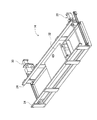
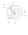
- FIG. 2 is a plan view showing the substrate apparatus shown in FIG. 1 with an upper cover removed. It is a perspective view which shows the conveying apparatus with which the to-substrate working machine shown in FIG. 1 is provided. It is a block diagram which shows the control apparatus with which the to-substrate working machine shown in FIG. 1 is provided. It is the schematic which shows the cross section of an optical wireless communication apparatus. It is the schematic which shows the position of the 1st movable shielding member when an optical wireless communication apparatus moves to the right side of drawing, and the flow of the airflow of a cross ventilation path. It is the schematic which shows the position of the 2nd movable shielding member when an optical wireless communication apparatus moves to the left side of drawing, and the flow of the airflow of a cross ventilation path.
- FIG. 1 and 2 show a substrate working machine (hereinafter, may be abbreviated as “working machine”) 10 according to an embodiment of the present invention.
- FIG. 1 is a perspective view of the work machine 10
- FIG. 2 is a schematic plan view showing the work machine 10 with the upper cover removed from a viewpoint from above.
- the work machine 10 is a circuit component mounting machine for mounting circuit components on the circuit board 12, and includes a transport device 14 for transporting the circuit board 12 and an operating head 16 for mounting circuit components on the circuit board 12. And a moving device 18 for moving the work head 16 and a pair of supply devices 20 and 22 for supplying circuit components.
- the transport device 14 has a pair of conveyor belts 24, and a circuit board supported by the conveyor belt 24 by rotating the pair of conveyor belts 24 by an electromagnetic motor 26. 12 is transported.
- One of the pair of conveyor belts 24 is fixed to the base 28, and the other is structured to be movable in a direction perpendicular to the conveying direction of the circuit board 12 by the conveying device 14.
- the mechanism 30 allows the other conveyor belt 24 to approach and separate from one conveyor belt 24. That is, the transfer device 14 can change the distance between the pair of conveyor belts 24 and can transfer circuit boards having different sizes.
- the transfer device 14 further includes a substrate holding device 32, and is configured to hold the circuit board 12 fixedly at a predetermined position (a position where the circuit board 12 in FIG. 2 is illustrated). .
- the transport direction of the circuit board 12 by the transport device 14 (the left-right direction in FIG. 2) is referred to as the X-axis direction, and the direction perpendicular to the direction is referred to as the Y-axis direction.
- the work head 16 is for mounting circuit components on the circuit board 12 held by the transfer device 14 and is a mounting head having a suction nozzle 34 for sucking circuit components on the lower surface.
- the suction nozzle 34 communicates with negative pressure air and a positive pressure air passage via a positive / negative pressure supply device 36 (see FIG. 4), sucks and holds the circuit components with negative pressure, and supplies a slight positive pressure. In this way, the held circuit components are detached.
- the working head 16 has a nozzle lifting device (see FIG. 4) 38 that lifts and lowers the suction nozzle 34 and a nozzle rotation device (see FIG. 4) 40 that rotates the suction nozzle 34 about its axis. It is possible to change the vertical position of the circuit component to be held and the holding posture of the circuit component.
- the suction nozzle 34 is attachable to and detachable from the work head 16 and can be changed according to the size and shape of the circuit components.
- the working head 16 can be moved to an arbitrary position on the base 28 by the moving device 18.
- the moving device 18 includes an X-axis direction slide mechanism 50 for moving the work head 16 in the X-axis direction, and a Y-axis direction slide mechanism 52 for moving the work head 16 in the Y-axis direction.
- the X-axis direction slide mechanism 50 has an X-axis slider 54 provided on the base 28 so as to be movable in the X-axis direction, and an electromagnetic motor (see FIG. 4) 56 as a drive source. 56, the X-axis slider 54 can be moved to an arbitrary position in the X-axis direction.
- the Y-axis direction slide mechanism 52 has a Y-axis slider 58 provided on the side surface of the X-axis slider 54 so as to be movable in the Y-axis direction, and an electromagnetic motor (see FIG. 4) 60 as a drive source.
- the Y-axis slider 58 can be moved to an arbitrary position in the Y-axis direction by the electromagnetic motor 60.
- the work head 16 can be moved to an arbitrary position on the base 28 by the moving device 18.
- the work head 16 can be attached to and detached from the Y-axis slider 58 with one touch, and can be changed to a different type of work head, such as a dispenser head.
- the pair of supply devices 20 and 22 are disposed on both sides of the base 28 in the Y-axis direction so as to sandwich the transport device 14.
- One of the pair of supply devices 20, 22 is a feeder-type supply device 20, and the other is a tray-type supply device 22.
- the feeder-type supply device 20 has a plurality of tape feeders 70 that hold the taped circuit components and send out the circuit components one by one, and each of the plurality of tape feeders 70 supplies the work head 16 to the work head 16.
- the circuit component is supplied to the supply position.
- the tray-type supply device 22 has a plurality of component trays 72 on which a plurality of circuit components are placed, and any one of the plurality of component trays 72 is connected to a tray moving mechanism 74 (see FIG. 4). ) To move to the supply position to the work head 16.
- the supply devices 20 and 22 can be attached to and detached from the base 28 in order to cope with a shortage of circuit components to be supplied, replacement of the types of circuit components, and the like.
- Supply device fixing mechanisms (see FIG. 4) 76 and 78 for maintaining the attached state, that is, fixing the supply devices 20 and 22 to the base 28 are provided.
- Each of the supply device fixing mechanisms 76 and 78 can be switched between a state where the supply devices 20 and 22 are locked so that they cannot be removed from the base 28 and a state where the lock is released. That is, it is possible to switch between the state where the replacement of the supply devices 20 and 22 is prohibited and the state where it is allowed.
- the mobile device 18 is provided with an optical wireless communication device 120.
- the optical wireless communication device 120 is an X-axis slider of the moving device 18 so that the optical axis coincides with a light emitting / receiving unit (not shown) provided on the control device 90 (described later) side as a counterpart of optical wireless communication. 54.
- various position information and drive control information can be communicated between the light emitting / receiving unit 122 (described later) of the optical wireless communication device 120 and the light emitting / receiving unit on the control device 90 side.
- the work machine 10 includes a mark camera (see FIG. 4) 80 and a parts camera (see FIG. 4) 82.
- the mark camera 80 is fixed to the lower surface of the Y-axis slider 58 so as to face downward, and is moved by the moving device 18 so that the surface of the circuit board 12 can be imaged at an arbitrary position. ing.
- the parts camera 82 is provided in a state of facing upward, and can pick up an image of a circuit component sucked and held by the suction nozzle 34 of the work head 16.
- the image data obtained by the mark camera 80 and the image data obtained by the parts camera 82 are processed by the image processing device 84 (see FIG. 4), and information on the circuit board 12 and the circuit board 12 by the board holding device 32 are processed.
- a holding position error, a holding position error of the circuit component by the suction nozzle 34, and the like are acquired.
- the work machine 10 includes a control device 90 as shown in FIG.
- the control device 90 includes a controller 92 mainly composed of a computer having a CPU, a ROM, a RAM, the electromagnetic motors 26, 56, 60, the conveyor width changing mechanism 30, the substrate holding device 32, the positive / negative pressure supply device 36, and a nozzle.
- a plurality of drive circuits 94 corresponding to each of the lifting device 38, the nozzle rotation device 40, the tape feeder 70, the tray moving mechanism 74, and the supply device fixing mechanisms 76 and 78, and a control circuit 96 for the display devices 86 and 88 are provided. Yes.
- the controller 92 is connected to an image processing device 84 that processes image data obtained by the mark camera 80 and the part camera 82, and three detection sensors 98. These three detection sensors 98 are arranged on the base 28 between the pair of conveyor belts 24 so as to face upward, and one is at the end on the side where the circuit board 12 is carried in, One is disposed at an end portion on the side to be carried out, and one is disposed at a position where the circuit board 12 is held by the board holding device 32.
- Information about the circuit board 12 obtained from the image data processed by the image processing device 84, information on the holding position of the circuit board 12, suction information by the suction nozzle 34, and the like are transmitted by the optical wireless communication device 120 provided in the moving device 18. Are transmitted to the controller 92 provided in the control device 90.
- the controller 92 issues a drive control command to each of the devices 14, 18, 16, and the like such as the conveying device, the moving device, and the mounting head via each driving circuit 94, and the conveying device, the moving device, and the mounting head It is possible to control the operation of each device 14, 18, 16, etc.
- the drive control command for the operation of each of the devices 18 and 16 is received from the driving circuit 94 via the controller 92 by the optical wireless communication device 120 provided in the moving device 18.
- the work machine 10 is provided with a pair of display devices 86 and 88 on both side surfaces in the Y-axis direction.
- Each of the display devices 86 and 88 is information related to the mounting work by the work head 16 and the like, and is a touch panel type display device.
- Display devices 86 and 88 are connected to the controller 92, and an operation result of a touch button displayed on the display devices 86 and 88 is input.
- Various information can be displayed via the control circuit 96.
- the work machine 10 is provided with a control power source and a driving power source.
- the driving power source is a power source for the transport device 14 and the supply device fixing mechanisms 76 and 78, and the transport device 14 and the supply device. It is divided into a power source for devices other than the fixing mechanisms 76 and 78. That is, the work machine 10 is provided with three power sources: a power source corresponding to the control device 90, a power source corresponding to the transport device 14 and the supply device fixing mechanisms 76 and 78, and a power source corresponding to the moving device 18 and the like. ing.
- the optical wireless communication device 120 provided in the mobile device 18 and the controller 92 can communicate with each other with the above-described configuration.
- the image data processed by the image processing device 84 is communicated from the moving device 18 to the controller 92, and the drive control command for the operation of each device 18, 16, such as the moving device and the mounting head, is moved from the controller 92.
- the optical wireless communication device 120 is provided in the X-axis slider 54 of the moving device 18 so that it can move in the optical axis direction.
- static electricity may be generated on the light transmission surface of the light receiving and emitting unit of the optical wireless communication apparatus 120 due to the flow of air.
- dust such as dust is adsorbed on the light transmission surface, which may hinder the transmission of the optical signal.
- a configuration for effectively air blowing dust on the surface will be described.
- FIG. 5 is a schematic diagram showing a cross section of the optical wireless communication device 120. It is the schematic of the cross section containing the optical axis AX which is in agreement with the other party of the optical wireless communication with which the control apparatus 90 side is provided, The optical axis AX, the light emitting / receiving part 122, and the path
- the optical wireless communication device 120 includes a light emitting / receiving unit 122, a transverse ventilation path 130, an optical signal propagation hole 132, a first ventilation path 134, a first shutter 136, a second ventilation path 138, a second shutter 140, and a first movable shielding member. 142 and a second movable shielding member 145 are provided.
- a path through which an air flow flows is constituted by the transverse ventilation path 130, the first ventilation path 134, and the second ventilation path 138.
- the light emitting / receiving unit 122 is a member that receives and emits an optical signal in optical wireless communication, and includes a light emitting / receiving element 124, a lens 126, and a protective glass 128.
- the light emitting / receiving element 124 includes a light receiving element such as a photodiode for receiving an optical signal and a light emitting element such as a laser diode or a light emitting diode for emitting an optical signal, and receives and emits an optical signal along the optical axis AX. It is provided along the optical axis AX so as to be possible.
- the lens 126 is provided to satisfy various optical characteristics such as condensing optical signals between the light emitting / receiving element 124 and the optical axis AX.
- the protective glass 128 is attached to the entrance / exit of the optical signal of the light emitting / receiving unit 122. It is formed of optical glass or the like that transmits the wavelength of the optical signal, and is provided to protect the light emitting / receiving element 124 and the lens 126 from dust and damage.
- the optical signal entering / exiting the light emitting / receiving unit 122 propagates through the optical signal propagation hole 132 opened along the optical axis AX.
- the optical signal propagation hole 132 is opened in the optical signal propagation path including the optical axis AX.
- the light emitting / receiving unit 122 is provided in the innermost part of the optical signal propagation hole 132 opposite to the opening side.
- the light receiving / emitting unit 122 is provided with a protective glass 128 serving as a light transmission surface thereof at an angle substantially perpendicular to the optical axis AX.
- the transverse ventilation path 130 is opened in a direction substantially orthogonal to the optical signal propagation hole 132.
- the protective glass 128 of the light emitting / receiving unit 122 is exposed and disposed on the wall surface of the inner wall surface of the transverse ventilation path 130 that collides with the extension line of the optical signal propagation hole 132.
- the first ventilation path 134 and the second ventilation path 138 are paths for introducing an air flow accompanying the movement of the optical wireless communication apparatus 120 in the optical axis AX direction.
- the first ventilation path 134 is opened in parallel to the optical signal propagation hole 132 toward the front of the light emitting / receiving unit 122.
- the open end of the first ventilation path 134 is a ventilation hole into which an air flow is introduced when the optical wireless communication device 120 moves toward the front of the light emitting / receiving unit 122.
- the other end of the first ventilation path 134 communicates with one end of the transverse ventilation path 130 so as to allow ventilation.
- the air intake hole of the first ventilation path 134 is provided with a first shutter 136 that closes the air intake hole when the movement acceleration of the optical wireless communication device 120 is equal to or less than a reference value.
- the second ventilation path 138 is opened in parallel to the optical signal propagation hole 132 toward the rear of the light emitting / receiving unit 122.
- the open end of the second ventilation path 138 is a ventilation hole into which an air flow is introduced when the optical wireless communication apparatus 120 moves toward the rear of the light emitting / receiving unit 122.
- the other end of the second ventilation path 138 communicates with the other end of the transverse ventilation path 130 so as to allow ventilation.
- the air intake hole of the second ventilation path 138 is provided with a second shutter 140 that closes the air intake hole when the movement acceleration of the optical wireless communication apparatus 120 is equal to or less than a reference value.
- the first shutter 136 and the second shutter 140 are opened, and the movement direction is increased.
- An air flow is taken in from the air intake hole facing. That is, when moving toward the front of the light emitting / receiving unit 122, the air flow taken from the air intake hole of the first ventilation path 134 passes through the transverse ventilation path 130 and is discharged from the second ventilation path 138.
- the optical signal propagation hole 132 is also opened toward the front of the light emitting / receiving unit 122, so that an air flow is also taken in from the optical signal propagation hole 132.
- the air flow taken from the air intake hole of the second ventilation path 138 passes through the transverse ventilation path 130 and is discharged from the first ventilation path 134.
- the first movable shielding member 142 is on the opposite side of the light receiving / emitting section 122 across the transverse ventilation path 130, so that the optical signal propagation hole 132 and the first ventilation path 134 are not interfered with the optical signal propagation hole 132. Between. An end of the first movable shielding member 142 is pivotally supported by the first fulcrum portion 144 so that the first movable shielding member 142 can rotate.
- the second movable shielding member 145 is on the opposite side of the light emitting / receiving section 122 across the transverse ventilation path 130, and the first movable shielding member across the optical signal propagation hole 132 so as not to interfere with the optical signal propagation hole 132.
- 142 is provided opposite to 142.
- the shielding portion 146 and the weight portion 148 are connected, and this connecting portion is pivotally supported by the second fulcrum portion 150 so as to be rotatable.
- the shielding portion 146 of the first movable shielding member 142 and the second movable shielding member 145 is housed in the inner wall portion of the transverse ventilation path 130.
- FIG. 6 is a schematic diagram showing the position of the first movable shielding member 142 and the air flow in the transverse ventilation path 130 when the optical wireless communication apparatus 120 moves to the right side of the drawing, which is in front of the light emitting / receiving unit 122. is there.
- the movement acceleration of the optical wireless communication apparatus 120 is equal to or higher than a reference value, and the first shutter 136 and the second shutter 140 are opened.
- the optical wireless communication device 120 moves forward, the air flow taken from the air sampling hole of the first ventilation path 134 flows into the transverse ventilation path 130.
- the air flow taken in from the optical signal propagation hole 132 is also the first ventilation path.
- the air flows into the transverse ventilation passage 130 in the same manner as the air flow taken in from the 134 air holes.
- the first movable shielding member 142 cannot move together due to the law of inertia and remains in a stationary state, or the movement is delayed. It will be. As a result, the first movable shielding member 142 rotates clockwise around the first fulcrum part 144 and moves relatively to the left in the drawing. As a result, the first movable shielding member 142 protrudes into the transverse ventilation path 130 and the cross-sectional area of the ventilation path of the transverse ventilation path 130 is reduced.
- the ventilation path of the transverse ventilation path 130 is narrowed by being unevenly distributed on the side where the space on the front side is restricted and the protective glass 128 of the light emitting and receiving unit 122 is exposed. Since the cross-sectional area is narrowed because the ventilation path of the transverse ventilation path 130 is unevenly distributed on the protective glass 128 side, the air flow taken from the air sampling hole of the first ventilation path 134 is protected by increasing the flow velocity and the air pressure. The air flows in a concentrated manner in the path where the glass 128 is disposed, and the air blowing of the protective glass 128 can be performed effectively.
- the air flow taken in from the optical signal propagation hole 132 can also blow the protective glass 128 together with the air flow taken in from the air sampling hole of the first ventilation path 134. Thereby, the flow velocity and air pressure of the air flow for air blowing the protective glass 128 are further increased.
- FIG. 7 shows the position of the shielding portion 146 provided in the second movable shielding member 145 and the air in the transverse ventilation path 130 when the optical wireless communication device 120 moves to the left side of the drawing behind the light emitting / receiving portion 122. It is the schematic which shows a flow. In FIG. 7, it is assumed that the movement acceleration of the optical wireless communication apparatus 120 is equal to or higher than a reference value, and the first shutter 136 and the second shutter 140 are opened. As the optical wireless communication device 120 moves rearward, the air flow taken from the air sampling hole of the second ventilation path 138 flows into the transverse ventilation path 130.
- the weight part 148 of the second movable shielding member 145 is maintained in a stationary state or delayed in movement due to the law of inertia. 2
- the movable shielding member 145 rotates counterclockwise about the second fulcrum 150, the weight 148 moves relative to the right in the drawing, and the shielding 146 moves relative to the left in the drawing, which is the opposite. To do. Thereby, the shielding part 146 protrudes into the transverse ventilation path 130, and the cross-sectional area of the ventilation path of the transverse ventilation path 130 is narrowed.
- the ventilation path of the transverse ventilation path 130 is narrowed by being unevenly distributed on the side where the space on the front side is restricted and the protective glass 128 of the light emitting and receiving unit 122 is exposed. Since the ventilation path of the cross ventilation path 130 is unevenly distributed on the protective glass 128 side and the cross-sectional area is narrowed, the air flow taken from the air sampling holes of the second ventilation path 138 is protected by increasing the flow velocity and the air pressure. The air flows in a concentrated manner in the path where the glass 128 is disposed, and the air blowing of the protective glass 128 can be performed effectively.
- the first movable shielding member 142 protrudes into the transverse ventilation path 130.
- the shielding part 146 of the second movable shielding member 145 projects into the transverse ventilation path 130 in the ventilation path of the transverse ventilation path 130. Since the first movable shielding member 142 or the shielding part 146 protrudes, the ventilation path of the transverse ventilation path 130 is unevenly distributed on the side where the space on the front side is restricted and the protective glass 128 of the light emitting and receiving part 122 is exposed.
- the cross-sectional area is narrowed.
- the air flow taken in from the air intake holes of the first ventilation path 134 or the second ventilation path 138 has a higher flow velocity and air pressure, and can flow in a concentrated manner in the path where the protective glass 128 is disposed. It becomes.
- it is possible to blow off the dust by effectively blowing the air to the protective glass 128, and it is possible to prevent the dust from adhering to and accumulating on the protective glass 128.
- the first shutter 136 and the second shutter 140 are closed, and the first ventilation path 134 and the second ventilation path 138 are closed.
- the first ventilation path 134 is obtained.
- the air flow that flows through the first ventilation path 134 and the second ventilation path 138 enables heat radiation of the light emitting / receiving unit 122 and the light emitting / receiving element 124.
- this invention is not limited to the said Example, It is possible to implement in the various aspect which gave various change and improvement based on the knowledge of those skilled in the art.
- the first fulcrum portion 144 of the first movable shielding member 142 is provided between the optical signal propagation hole 132 and the first ventilation path 134 and on the first ventilation path 134 side.
- the present application is not limited to this. If the optical wireless communication device 120 can project to the transverse ventilation path 130 when moving in front of the light emitting / receiving unit 122, the first fulcrum part 144 is provided on the optical signal propagation hole 132 side. Also good.
- FIG. 5 the first fulcrum portion 144 of the first movable shielding member 142 is provided between the optical signal propagation hole 132 and the first ventilation path 134 and on the first ventilation path 134 side.
- the present application is not limited to this. If the optical wireless communication device 120 can project to the transverse ventilation path 130 when moving in front of the light emitting / receiving unit 122, the first
- the shielding part 146 of the second movable shielding member 145 is provided on the optical signal propagation hole 132 side with respect to the second fulcrum part 150, but the present application is not limited to this. It may be provided on the second ventilation path 138 side. Further, when the optical wireless communication apparatus 120 moves in front of the light emitting / receiving unit 122, the first movable shielding member 142 protrudes into the transverse ventilation path 130 and the sectional area of the ventilation path of the transverse ventilation path 130 is reduced. Well, it is not limited to the above embodiment.
- the light receiving / emitting element 124 provided in the light receiving / emitting unit 122 is not limited to having both functions of a light receiving element that receives light signals and a light emitting element that emits light signals. Only one of the light receiving element and the light emitting element may be provided. In this case, the light emitting / receiving unit 122 functions as a light receiving unit or a light emitting unit.
- the light emitting / receiving part 122 is an example of a communication part
- the protective glass 128 is an example of the light transmissive surface of a communication part.
Landscapes
- Engineering & Computer Science (AREA)
- Manufacturing & Machinery (AREA)
- Microelectronics & Electronic Packaging (AREA)
- Automation & Control Theory (AREA)
- Operations Research (AREA)
- Optical Communication System (AREA)
Description
本発明は、移動可能に備えられる光無線通信装置に関するものであり、光信号を発光あるいは受光、または受発光する通信部の光透過面の塵埃をエアブローする空気流が装置の移動に応じて導入される光無線通信装置に関するものである。
光学ヘッドを備えたディスクドライブ装置において、光学ヘッドのレンズ清掃機構として、少なくとも一つのエアインテークを搭載する構成が開示されている(特許文献1など)。このエアインテークは、シーク方向に向かって開口した導入部と、対物レンズ表面に向かって臨接配置されたノズルと、導入部とノズルとを連通する小径の管部とを備えて構成されている。光学ヘッドのシーク方向への移動時に、導入部から導入された空気が管部によって流速を高められて、ノズルより対物レンズ表面に噴射される。
上記特許文献1に記載のレンズ清掃機構は、ディスクドライブ装置に搭載されている光学ヘッドの対物レンズを清掃するという特定の用途に特化した構成である。清掃の対象となる対物レンズはディスクドライブ装置に搭載されている光学ヘッドに納められたものである。ディスクドライブ装置は特定の環境の中で特定の動作を行うものであり、レンズ清掃機構は、こうした使用環境の条件に適合して構成すれば足りるものである。この前提に立って、導入部から小径の管部を経てノズルに到るエアインテークが構成されている。光無線通信装置とは技術分野が異なっており、上記特許文献1に開示の構成を光無線通信装置に適用することは十分でない場合もある。
特に、光無線通信装置が移動可能に備えられている場合、装置の移動環境は様々であり、移動に応じて通気経路が柔軟に構成されることが望まれる。上記特許文献1に記載の構成では、空気流の導入経路が固定的に構成されており、この点、移動可能な光無線通信装置に適用するに際して改善が望まれる。
本発明は、そのような実情に鑑みてなされたものであり、移動可能に備えられる光無線装置において、装置の移動に応じて起風され導入される空気流を、空気流の方向に応じて光信号の光透過面に効率よくブローして光透過面の塵埃を吹き飛ばすことが可能な光無線通信装置を提供ことを目的とする。
上記課題を解決するために、本願の請求項1に記載の光無線通信装置は、移動可能に備えられる光無線通信装置であって、光信号伝搬孔、通信部、採気孔、および通気経路を備える。光信号伝搬孔は、光軸を含む光信号の伝搬経路に開孔される。通信部は、光信号伝搬孔の端部に備えられて光信号を発光する発光部、受光する受光部、若しくは受発光する受発光部の何れかを備える。採気孔は、光無線通信装置の移動方向に臨む空気流の導入口である。通気経路は、移動に応じて採気孔から導入され通信部の光透過面の塵埃をエアブローする空気流が流れる経路であって、光信号伝搬孔に交差する経路である。光無線通信装置の移動に応じて、採気孔に連接する領域にある経路の断面積より通信部の光透過面が存在する領域にある経路の断面積が、狭小化する。
また、請求項2に記載の光無線通信装置は、光無線通信装置は光軸方向に移動可能とされる。通気経路は、横断通気経路、第1通気経路、第2通気経路、および第1可動遮蔽部材を備える。横断通気経路は、経路内に通信部の光透過面が露出して設けられ、光信号伝搬孔に交差する。第1通気経路は、横断通気経路の一端に連通され、通信部の前方に向かって光信号伝搬孔に平行に開孔される。第2通気経路は、横断通気経路の他端に連通され、通信部の後方に向かって光信号伝搬孔に平行に開孔される。第1可動遮蔽部材は、横断通気経路を挟んで通信部の反対側であって光信号伝搬孔と第1通気経路との間に、横断通気経路内に突出可能に設けられる。また、端部が回動可能に軸支され、光無線通信装置が通信部の前方に移動することに応じて、横断通気経路内に突出する。
また、請求項3に記載の光無線通信装置は、第2可動遮蔽部材を備える。第2可動遮蔽部材は、横断通気経路を挟んで通信部の反対側であって光信号伝搬孔を挟んで第1可動遮蔽部材に対向して設けられる。横断通気経路内に突出可能に設けられる遮蔽部、および遮蔽部に連接されるおもり部を備えている。また、遮蔽部とおもり部との連接部分が回動可能に軸支され、光無線通信装置が通信部の後方に移動することに応じて、遮蔽部が横断通気経路内に突出する。
また、請求項4に記載の光無線通信装置は、光無線通信装置の移動加速度が基準値以下の場合に、第1通気経路を閉じる第1シャッタと、第2通気経路を閉じる第2シャッタとを備える。
請求項1に記載の光無線通信装置では、装置の移動に応じて、通信部の光透過面をエアブローする空気流を導入する通気経路のうち、採気孔に連接する領域にある経路より通信部の光透過面が存在する領域にある経路で断面積が狭小となる。これにより、採気孔から導入された空気流は、通気経路を進みエアブローの対象である通信部の光透過面の近傍で流速と空気圧が高められる。通信部の光透過面における塵埃を効率よくエアブローすることができる。
この場合、通気経路の断面積の狭小化は光無線通信装置の移動に応じて行われる。移動方向はその都度異なるとしても、移動方向に応じて採気孔に連接する領域の断面積に比して光透過面がある領域の断面積を狭小化することができるため、移動方向に拘わらず、導入される空気流の進む方向に向かって通気経路の断面積を狭小化することができる。移動方向に拘わらず、光透過面での空気流の流速・圧力を高めて、効率よくエアブローを行うことができる。
また、請求項2に記載の光無線通信装置では第1可動遮蔽部材を備えている。第1可動遮蔽部材は、端部が回動可能に軸支され、光無線通信装置が通信部の前方に移動することに応じて、光信号伝搬孔と第1通気経路と間から横断通気経路内に突出する。第1可動遮蔽部材の突出により、第1通気経路から導入される空気流は、通信部の光透過面に到る通気経路で断面積が狭小化され、光透過面をエアブローする空気流の流速と空気圧とが高められる。光無線通信装置が通信部の前方に移動する際に、通信部の光透過面における塵埃のエアブローを効率よく行うことができる。
また、請求項3に記載の光無線通信装置では第2可動遮蔽部材を備えている。第2可動遮蔽部材は、遮蔽部とおもり部との連接部分が回動可能に軸支され、光無線通信装置が通信部の後方に移動することに応じて、横断通気経路を挟んで通信部の反対側にあって光信号伝搬孔を挟んで第1通気経路と対向する側から遮蔽部が横断通気経路内に突出する。遮蔽部の突出により、第2通気経路から導入される空気流は、通信部の光透過面に到る通気経路で断面積が狭小化され、光透過面をエアブローする空気流の流速と空気圧とが高められる。光無線通信装置が通信部の後方に移動する際に、通信部の光透過面における塵埃のエアブローを効率よく行うことができる。
また、請求項4に記載の光無線通信装置では、光無線通信装置の移動加速度が基準値以下の場合に、第1シャッタおよび第2シャッタは閉じ、第1通気経路および第2通気経路を閉路とする。これにより、光無線通信装置が静止若しくは基準の移動加速度以下で移動しており、通信部の光透過面のエアブローに十分な空気流が得られない場合には、第1通気経路および第2通気経路を閉路とすることで、通気経路内への塵埃等の進入を防止することができる。
以下、本発明を実施するための形態として、本発明の実施例を、図を参照しつつ詳しく説明する。
<対基板作業機の構成>
図1および図2に、本発明の実施例の対基板作業機(以下、「作業機」と略す場合がある)10を示す。図1は、作業機10の斜視図であり、図2は、上部カバーを取り除いた状態での作業機10を上方からの視点において示した概略平面図である。作業機10は、回路基板12に対して回路部品の装着作業を行う回路部品装着機であり、回路基板12を搬送する搬送装置14と、回路基板12に対して回路部品を装着する作動ヘッド16と、その作業ヘッド16を移動させる移動装置18と、回路部品を供給する1対の供給装置20、22とを備えている。
図1および図2に、本発明の実施例の対基板作業機(以下、「作業機」と略す場合がある)10を示す。図1は、作業機10の斜視図であり、図2は、上部カバーを取り除いた状態での作業機10を上方からの視点において示した概略平面図である。作業機10は、回路基板12に対して回路部品の装着作業を行う回路部品装着機であり、回路基板12を搬送する搬送装置14と、回路基板12に対して回路部品を装着する作動ヘッド16と、その作業ヘッド16を移動させる移動装置18と、回路部品を供給する1対の供給装置20、22とを備えている。
搬送装置14は、図3に示すように、1対のコンベアベルト24を有しており、それら1対のコンベアベルト24を電磁モータ26によって周回させることで、コンベアベルト24に支持される回路基板12を搬送する構造とされている。それら1対のコンベアベルト24の一方は、ベース28に固定され、他方は、搬送装置14による回路基板12の搬送方向に直角な方向に移動させることが可能な構造とされており、コンベア幅替え機構30によって、その他方のコンベアベルト24を一方のコンベアベルト24に接近離間させることが可能となっている。つまり、搬送装置14は、1対のコンベアベルト24の間の距離を変更することが可能となっており、サイズの異なる回路基板を搬送することが可能となっている。搬送装置14は、さらに、基板保持装置32を有しており、所定の位置(図2での回路基板12が図示されている位置)において回路基板12を固定的に保持する構造とされている。なお、本実施例では、搬送装置14による回路基板12の搬送方向(図2における左右方向)をX軸方向とし、その方向に直角な方向をY軸方向と称し、説明を行う。
また、作業ヘッド16は、搬送装置14によって保持された回路基板12に対して回路部品を装着するものであり、下面に回路部品を吸着する吸着ノズル34を有する装着ヘッドである。吸着ノズル34は、正負圧供給装置36(図4参照)を介して負圧エア、正圧エア通路に通じており、負圧にて回路部品を吸着保持し、僅かな正圧が供給されることで保持した回路部品を離脱する構造とされている。さらに、作業ヘッド16は、吸着ノズル34を昇降させるノズル昇降装置(図4参照)38および吸着ノズル34をそれの軸心回りに自転させるノズル自転装置(図4参照)40を有しており、保持する回路部品の上下方向の位置および回路部品の保持姿勢を変更することが可能とされている。なお、吸着ノズル34は、作業ヘッド16に着脱可能とされており、回路部品のサイズ、形状等に応じて変更することが可能とされている。
その作業ヘッド16は、移動装置18によって、ベース28上の任意の位置に移動可能とされている。詳しく言えば、移動装置18は、作業ヘッド16をX軸方向に移動させるためのX軸方向スライド機構50と、作業ヘッド16をY軸方向に移動させるためのY軸方向スライド機構52とを備えている。X軸方向スライド機構50は、X軸方向に移動可能にベース28上に設けられたX軸スライダ54と、駆動源としての電磁モータ(図4参照)56とを有しており、その電磁モータ56によって、X軸スライダ54がX軸方向の任意の位置に移動可能とされている。また、Y軸方向スライド機構52は、Y軸方向に移動可能にX軸スライダ54の側面に設けられたY軸スライダ58と、駆動源としての電磁モータ(図4参照)60とを有しており、その電磁モータ60によって、Y軸スライダ58がY軸方向の任意の位置に移動可能とされている。そして、そのY軸スライダ58に作業ヘッド16が取り付けられることで、作業ヘッド16は、移動装置18によって、ベース28上の任意の位置に移動可能とされている。なお、作業ヘッド16は、Y軸スライダ58にワンタッチで着脱可能とされており、種類の異なる作業ヘッド、例えば、ディスペンサヘッド等に変更することが可能とされている。
また、1対の供給装置20、22は、搬送装置14を挟むようにして、ベース28のY軸方向における両側部に配設されている。それら1対の供給装置20、22の一方は、フィーダ型の供給装置20とされており、他方は、トレイ型の供給装置22とされている。フィーダ型の供給装置20は、テーピング化された回路部品を保持して1つずつ回路部品を送り出すテープフィーダ70を複数有しており、それら複数のテープフィーダ70の各々によって、作業ヘッド16への供給位置に回路部品を供給する構造とされている。一方、トレイ型の供給装置22は、複数の回路部品が載置された部品トレイ72を複数有しており、それら複数の部品トレイ72のうちの任意のものをトレイ移動機構74(図4参照)によって作業ヘッド16への供給位置に移動させる構造とされている。
なお、各供給装置20、22は、供給するべき回路部品の不足、回路部品の種類の交換等に対応するべく、ベース28に着脱可能とされており、各供給装置20、22がベース28に取り付けられた状態を維持するため、つまり、各供給装置20、22をベース28に固定するための供給装置固定機構(図4参照)76、78が設けられている。各供給装置固定機構76、78は、供給装置20、22をベース28から取り外せないようにロックした状態と、そのロックを解除した状態とで切換可能とされている。つまり、供給装置20、22の交換が禁止された状態と許容された状態とで切換可能とされている
また、移動装置18には光無線通信装置120が備えられている。光無線通信装置120は、光無線通信の相手方として制御装置90(後述)側に備えられている受発光部(不図示)との間で光軸が一致するように移動装置18のX軸スライダ54に設けられる。これにより、光無線通信装置120の受発光部122(後述)と制御装置90側の受発光部との間で、各種の位置情報や駆動制御情報の通信をすることが可能となっている。
また、作業機10は、マークカメラ(図4参照)80およびパーツカメラ(図4参照)82を備えている。マークカメラ80は、下方を向いた状態でY軸スライダ58の下面に固定されており、移動装置18によって移動させられることで、回路基板12の表面を任意の位置において撮像することが可能となっている。一方、パーツカメラ82は、上を向いた状態で設けられており、作業ヘッド16の有する吸着ノズル34によって吸着保持された回路部品を撮像することが可能となっている。マークカメラ80によって得られた画像データおよび、パーツカメラ82によって得られた画像データは、画像処理装置84(図4参照)において処理され、回路基板12に関する情報、基板保持装置32による回路基板12の保持位置誤差、吸着ノズル34による回路部品の保持位置誤差等が取得される。
さらに、作業機10は、図4に示すように、制御装置90を備えている。制御装置90は、CPU、ROM、RAM等を備えたコンピュータを主体とするコントローラ92と、上記電磁モータ26、56、60、コンベア幅替機構30、基板保持装置32、正負圧供給装置36、ノズル昇降装置38、ノズル自転装置40、テープフィーダ70、トレイ移動機構74、供給装置固定機構76、78の各々に対応する複数の駆動回路94と、表示装置86、88の制御回路96とを備えている。コントローラ92には、マークカメラ80およびパーツカメラ82によって得られた画像データを処理する画像処理装置84、および、3つの検知センサ98が接続されている。それら3つの検知センサ98は、1対のコンベアベルト24の間のベース28上に上を向いた状態で配設されており、1つは、回路基板12が搬入される側の端部に、1つは、搬出される側の端部に、1つは、回路基板12が基板保持装置32に保持される位置に配設されている。
画像処理装置84によって処理された画像データによって得られる回路基板12に関する情報、回路基板12の保持位置情報、吸着ノズル34による吸着情報等の情報は、移動装置18に備えられる光無線通信装置120により、制御装置90に備えられるコントローラ92に送信される。
また、コントローラ92には、各駆動回路94を介して搬送装置、移動装置、装着ヘッド等の各装置14、18、16等に対して駆動制御指令が発せられ、搬送装置、移動装置、装着ヘッド等の各装置14、18、16等の作動を制御することが可能とされている。移動装置、装着ヘッド等の各装置18、16等の作動の駆動制御指令は、移動装置18に備えられる光無線通信装置120により、コントローラ92を介して駆動回路94から受信される。
また、作業機10には、図1に示すように、Y軸方向における両側面に1対の表示装置86、88が設けられている。各表示装置86、88は、作業ヘッド16等による装着作業に関する情報であり、タッチパネル式の表示装置とされている。コントローラ92には、表示装置86、88が接続されており、表示装置86、88に表示されるタッチボタンの操作結果が入力されるようになっている。また、制御回路96を介して各種情報を表示することが可能とされている。
ちなみに、作業機10では、制御用電源と駆動用電源とが設けられており、駆動用電源は、搬送装置14および供給装置固定機構76、78のための電源と、それら搬送装置14および供給装置固定機構76、78以外の装置のための電源とに分けられている。つまり、作業機10には、制御装置90に対応した電源と、搬送装置14および供給装置固定機構76、78に対応した電源と、移動装置18等に対応した電源との3つの電源が設けられている。
さて、作業機10では、上述した構成によって、移動装置18に備えられる光無線通信装置120とコントローラ92とが通信することが可能となっている。これにより、画像処理装置84によって処理された画像データが移動装置18からコントローラ92に向けて通信され、移動装置、装着ヘッド等の各装置18、16等の作動の駆動制御指令がコントローラ92から移動装置18に向けて通信される。また、光無線通信装置120は、移動装置18のX軸スライダ54に備えられることで、光軸方向に移動可能とされている。X軸スライダ54が移動する際に、光無線通信装置120の受発光部の光透過面には、空気の流れにより、静電気が発生する場合がある。これにより、光透過面にホコリ等の塵埃が吸着し、光信号の透過の妨げになるおそれがあった。以下では、表面の塵埃を有効にエアブローする構成について説明する。
図5は、光無線通信装置120の断面を示す概略図である。制御装置90側に備えられる光無線通信の相手方との間で一致する光軸AXを含む断面の概略図であり、光軸AX、受発光部122、およびエアブローのための空気流が流れる経路を示す図である。
光無線通信装置120は、受発光部122、横断通気経路130、光信号伝搬孔132、第1通気経路134、第1シャッタ136、第2通気経路138、第2シャッタ140、第1可動遮蔽部材142、および第2可動遮蔽部材145が備えられる。ここで、横断通気経路130、第1通気経路134、および第2通気経路138で空気流が流れる経路が構成される。
受発光部122は、光無線通信における光信号の受発光を行う部材であり、受発光素子124、レンズ126、および保護ガラス128を備える。受発光素子124は、光信号の受光を行うフォトダイオード等の受光素子、および光信号の発光を行うレーザダイオードや発光ダイオード等の発光素子を備え、光軸AXに沿って光信号の受発光が可能となるように、光軸AXに沿って設けられる。レンズ126は、受発光素子124と光軸AXとの間で光信号の集光等の各種の光学特性を満足させるために備えられる。保護ガラス128は受発光部122の光信号の出入口に装着される。光信号の波長を透過する光学ガラス等により形成され、受発光素子124およびレンズ126を塵埃や破損から保護するために設けられる。
受発光部122に出入する光信号は、光軸AXに沿って開孔された光信号伝搬孔132を通って伝搬する。光信号伝搬孔132は光軸AXを含む光信号の伝搬経路に開孔されている。光信号伝搬孔132の開孔側とは反対側の最奥部に受発光部122が備えられる。受発光部122はその光透過面である保護ガラス128を光軸AXに対してほぼ垂直をなす角度で配設されている。
横断通気経路130は、光信号伝搬孔132と略直交する方向に開孔されている。横断通気経路130の内壁面のうち光信号伝搬孔132の延長線とぶつかる壁面に、受発光部122の保護ガラス128が露出して配設されている。
第1通気経路134および第2通気経路138は、光無線通信装置120が光軸AX方向に移動することに伴う空気流を導入するための経路である。
第1通気経路134は、受発光部122の前方に向かって光信号伝搬孔132に平行に延びて開孔されている。第1通気経路134の開孔端は、受発光部122の前方に向かって光無線通信装置120が移動する際に空気流が導入される採気孔である。第1通気経路134の他端は横断通気経路130の一端に通気可能に連通される。第1通気経路134の採気孔には、光無線通信装置120の移動加速度が基準値以下の場合に採気孔を閉じる第1シャッタ136が備えられる。
第2通気経路138は、受発光部122の後方に向かって光信号伝搬孔132に平行に延びて開孔されている。第2通気経路138の開孔端は、受発光部122の後方に向かって光無線通信装置120が移動する際に空気流が導入される採気孔である。第2通気経路138の他端は横断通気経路130の他端に通気可能に連通される。第2通気経路138の採気孔には、光無線通信装置120の移動加速度が基準値以下の場合に採気孔を閉じる第2シャッタ140が備えられる。
光無線通信装置120が光軸AX方向に移動する際に、光無線通信装置120の移動加速度が基準値以上である場合には、第1シャッタ136および第2シャッタ140が開かれ、移動方向に臨む採気孔から空気流が取り込まれる。すなわち、受発光部122の前方に向かって移動する場合には、第1通気経路134の採気孔から取り込まれた空気流は、横断通気経路130を通り第2通気経路138から排出される。光信号伝搬孔132も、第1通気経路134と同様に、受発光部122の前方に向かって開孔されているので、光信号伝搬孔132からも空気流が取り込まれる。また、受発光部122の後方に向かって移動する場合には、第2通気経路138の採気孔から取り込まれた空気流は、横断通気経路130を通り第1通気経路134から排出される。
第1可動遮蔽部材142は、横断通気経路130を挟んで受発光部122とは反対側であって、光信号伝搬孔132に干渉しないように、光信号伝搬孔132と第1通気経路134との間に設けられる。第1可動遮蔽部材142の端部は、第1支点部144によって、第1可動遮蔽部材142を回動可能に軸支される。
第2可動遮蔽部材145は、横断通気経路130を挟んで受発光部122の反対側であって、光信号伝搬孔132に干渉しないように、光信号伝搬孔132を挟んで第1可動遮蔽部材142に対向して設けられる。第2可動遮蔽部材145は、遮蔽部146とおもり部148とが連結されており、この連結部分が第2支点部150によって回動可能に軸支される。
光無線通信装置120の静止状態において、第1可動遮蔽部材142および第2可動遮蔽部材145の遮蔽部146は、横断通気経路130の内壁部分に収納されている。
図6は、光無線通信装置120が、受発光部122の前方である図面右側に移動した際の、第1可動遮蔽部材142の位置、および横断通気経路130の空気の流れを示す概略図である。図6において、光無線通信装置120の移動加速度は基準値以上であり、第1シャッタ136および第2シャッタ140は開かれているものとする。光無線通信装置120の前方への移動に伴い、第1通気経路134の採気孔から取り込まれた空気流は横断通気経路130に流れ込む。また、光信号伝搬孔132は、第1通気経路134と同様に受発光部122の前方に向かって開孔されているので、光信号伝搬孔132から取り込まれた空気流も、第1通気経路134の採気孔から取り込まれた空気流と同様に、横断通気経路130に流れ込む。
光無線通信装置120が受発光部122の前方である図面右側に移動すると、第1可動遮蔽部材142は、慣性の法則により共に移動できず、静止状態での位置に留まるか、あるいは移動が遅れることとなる。結果として、第1可動遮蔽部材142は、第1支点部144を中心にして時計回りに回動して図面左方向へ相対的に移動する。これにより、第1可動遮蔽部材142が横断通気経路130に突出して横断通気経路130の通気経路の断面積は狭小化される。この場合、横断通気経路130の通気経路は、前方側の空間が規制され受発光部122の保護ガラス128が露出している側に偏在して狭められる。横断通気経路130の通気経路が保護ガラス128側に偏在して断面積が狭小化されることにより、第1通気経路134の採気孔から取り込まれた空気流は、流速と空気圧が高められて保護ガラス128の配設されている経路に集中して流れることとなり、有効に保護ガラス128のエアブローを行うことができる。これに加えて、光信号伝搬孔132から取り込まれた空気流も、第1通気経路134の採気孔から取り込まれた空気流と共に、保護ガラス128のエアブローを行うことができる。これにより、保護ガラス128をエアブローする空気流は、更に、流速と空気圧とが高められる。
図7は、光無線通信装置120が、受発光部122の後方である図面左側に移動した際の、第2可動遮蔽部材145に備えられる遮蔽部146の位置、および横断通気経路130の空気の流れを示す概略図である。図7において、光無線通信装置120の移動加速度は基準値以上であり、第1シャッタ136および第2シャッタ140は開かれているものとする。光無線通信装置120の後方への移動に伴い、第2通気経路138の採気孔から取り込まれた空気流が横断通気経路130に流れ込む。
光無線通信装置120が、受発光部122の後方である図面左側に移動すると、第2可動遮蔽部材145のおもり部148は、慣性の法則により静止状態が維持されるか移動が遅れるため、第2可動遮蔽部材145は、第2支点部150を中心にして反時計回りに回動しておもり部148は図面右方向へ相対移動し、遮蔽部146はその反対である図面左方向に相対移動する。これにより、遮蔽部146が横断通気経路130に突出して、横断通気経路130の通気経路の断面積は狭小化される。この場合、横断通気経路130の通気経路は、前方側の空間が規制され受発光部122の保護ガラス128が露出している側に偏在して狭められる。横断通気経路130の通気経路が保護ガラス128側に偏在して断面積が狭小化されることにより、第2通気経路138の採気孔から取り込まれた空気流は、流速と空気圧が高められて保護ガラス128の配設されている経路に集中して流れることとなり、有効に保護ガラス128のエアブローを行うことができる。
この場合、遮蔽部146も、おもり部148と同様に、慣性の法則が働くことも考えられるが、遮蔽部146の重量に比しておもり部148の重量を大きく設定することにより、遮蔽部146の回転モーメントは、おもり部148の回転モーメントと比べて小さくでき、遮蔽部146を有効に突出させることができる。
以上、詳細に説明した通り、本実施形態によれば、光無線通信装置120が受発光部122の前方に移動すると、第1可動遮蔽部材142が横断通気経路130に突出する。また、光無線通信装置120が受発光部122の後方に移動すると、横断通気経路130の通気経路は、第2可動遮蔽部材145の遮蔽部146が横断通気経路130に突出する。第1可動遮蔽部材142もしくは遮蔽部146が突出することで、横断通気経路130の通気経路は、前方側の空間が規制され受発光部122の保護ガラス128が露出している側に偏在して断面積が狭小化される。これにより、第1通気経路134もしくは第2通気経路138の採気孔から取り込まれた空気流は、流速と空気圧が高められ、保護ガラス128の配設されている経路に集中して流れることが可能となる。これにより、有効に保護ガラス128のエアブローを行うことで、塵埃を吹き飛ばすことができ、保護ガラス128における塵埃の付着および堆積を防止するが可能となる。
また、光無線通信装置120の移動加速度が基準値以下の場合に、第1シャッタ136および第2シャッタ140は閉じ、第1通気経路134および第2通気経路138を閉路とされる。これにより、光無線通信装置120が静止、若しくは基準の移動加速度以下で移動しており、受発光部122の保護ガラス128のエアブローに十分な空気流が得られない場合に、第1通気経路134および第2通気経路138から、横断通気経路130の通気経路内への塵埃等の進入を防止することが可能となっている。
また、第1通気経路134および第2通気経路138を通気する空気流により、受発光部122、および受発光素子124の放熱が可能となる。
なお、本発明は、上記実施例に限定されるものではなく、当業者の知識に基づいて種々の変更、改良を施した種々の態様で実施することが可能である。
具体的に例えば、図5では、第1可動遮蔽部材142の第1支点部144は、光信号伝搬孔132と第1通気経路134との間であって、第1通気経路134側に設けられているが、本願はこれに限定されるものではない。光無線通信装置120が受発光部122の前方に移動する際に、横断通気経路130に突出することが可能であれば、第1支点部144は、光信号伝搬孔132側に設けられていてもよい。同様に、図5では、第2可動遮蔽部材145の遮蔽部146が第2支点部150に対して光信号伝搬孔132側に設けられているが、本願はこれに限定されるものではない。第2通気経路138側に備えられていてもよい。
また、第1可動遮蔽部材142は、光無線通信装置120が受発光部122の前方に移動する際に、横断通気経路130に突出して横断通気経路130の通気経路の断面積は狭小化すればよく、上記実施例に限定されない。例えば、光信号伝搬孔132に平行に延びるレール上に摺動可能に設けておき、光無線通信装置120が受発光部122の前方に移動する際に、後方に移動可能にしてもよい。
また、受発光部122に備えられる受発光素子124は、光信号の受光を行う受光素子および光信号の発光を行う発光素子の両方の機能を備えることに限定されない。受光素子または発光素子の何れか一方を備えるだけでもよい。この場合、受発光部122は、受光部または発光部として機能する。
具体的に例えば、図5では、第1可動遮蔽部材142の第1支点部144は、光信号伝搬孔132と第1通気経路134との間であって、第1通気経路134側に設けられているが、本願はこれに限定されるものではない。光無線通信装置120が受発光部122の前方に移動する際に、横断通気経路130に突出することが可能であれば、第1支点部144は、光信号伝搬孔132側に設けられていてもよい。同様に、図5では、第2可動遮蔽部材145の遮蔽部146が第2支点部150に対して光信号伝搬孔132側に設けられているが、本願はこれに限定されるものではない。第2通気経路138側に備えられていてもよい。
また、第1可動遮蔽部材142は、光無線通信装置120が受発光部122の前方に移動する際に、横断通気経路130に突出して横断通気経路130の通気経路の断面積は狭小化すればよく、上記実施例に限定されない。例えば、光信号伝搬孔132に平行に延びるレール上に摺動可能に設けておき、光無線通信装置120が受発光部122の前方に移動する際に、後方に移動可能にしてもよい。
また、受発光部122に備えられる受発光素子124は、光信号の受光を行う受光素子および光信号の発光を行う発光素子の両方の機能を備えることに限定されない。受光素子または発光素子の何れか一方を備えるだけでもよい。この場合、受発光部122は、受光部または発光部として機能する。
ちなみに、上記実施例において、受発光部122は、通信部の一例であり、また、保護ガラス128は、通信部の光透過面の一例である。
10:作業機 14:搬送装置 16:作業ヘッド 18:移動装置 50:X軸方向スライド機構 54:X軸スライダ 120:光無線通信装置 AX:光軸 122:受発光部 124:受発光素子 126:レンズ 128:保護ガラス 130:横断通気経路 132:光信号伝搬孔 134:第1通気経路 136:第1シャッタ 138:第2通気経路 140:第2シャッタ 142:第1可動遮蔽部材 144:第1支点部 145:第2可動遮蔽部材 146:遮蔽部 148:おもり部
Claims (4)
- 移動可能に備えられる光無線通信装置であって、
光軸を含む光信号の伝搬経路に開孔される光信号伝搬孔と、
前記光信号伝搬孔の端部に備えられて前記光信号を発光する発光部、受光する受光部、若しくは受発光する受発光部の何れかを備える通信部と、
前記光無線通信装置の移動方向に臨む採気孔を備え、移動に応じて前記採気孔から導入され前記通信部の光透過面の塵埃をエアブローする空気流が流れる経路であって、前記光信号伝搬孔に交差する通気経路とを備え、
前記通気経路は、前記光無線通信装置の移動に応じて、前記採気孔に連接する領域にある経路に対して前記通信部の光透過面が存在する領域にある経路において断面積が狭小化することを特徴とする光無線通信装置。 - 前記光無線通信装置は前記光軸方向に移動可能とされ、
前記通気経路は、
経路内に前記通信部の光透過面が露出して設けられ、前記光信号伝搬孔に交差する横断通気経路と、
前記横断通気経路の一端に連通され、前記通信部の前方に向かって前記光信号伝搬孔に平行に開孔される第1通気経路と、
前記横断通気経路の他端に連通され、前記通信部の後方に向かって前記光信号伝搬孔に平行に開孔される第2通気経路と、
前記横断通気経路を挟んで前記通信部の反対側であって前記光信号伝搬孔と前記第1通気経路との間に設けられ、前記横断通気経路内に突出可能に設けられる第1可動遮蔽部材とを備え、
前記第1可動遮蔽部材は、端部が回動可能に軸支され、前記光無線通信装置が前記通信部の前方に移動することに応じて、前記横断通気経路内に突出することを特徴とする請求項1に記載の光無線通信装置。 - 前記横断通気経路を挟んで前記通信部の反対側であって前記光信号伝搬孔を挟んで前記第1可動遮蔽部材に対向して設けられる第2可動遮蔽部材を備え、
前記第2可動遮蔽部材は、
前記横断通気経路内に突出可能に設けられる遮蔽部と、
前記遮蔽部に連接されるおもり部とを備え、
前記遮蔽部と前記おもり部との連接部分が回動可能に軸支され、前記光無線通信装置が前記通信部の後方に移動することに応じて、前記遮蔽部が前記横断通気経路内に突出することを特徴とする請求項2に記載の光無線通信装置。 - 前記光無線通信装置の移動加速度が基準値以下の場合に、
前記第1通気経路を閉じる第1シャッタと、
前記第2通気経路を閉じる第2シャッタとを備えることを特徴とする請求項2又は3に記載の光無線通信装置。
Priority Applications (2)
| Application Number | Priority Date | Filing Date | Title |
|---|---|---|---|
| PCT/JP2012/058312 WO2013145200A1 (ja) | 2012-03-29 | 2012-03-29 | 光無線通信装置 |
| JP2014507166A JP5946902B2 (ja) | 2012-03-29 | 2012-03-29 | 光無線通信装置 |
Applications Claiming Priority (1)
| Application Number | Priority Date | Filing Date | Title |
|---|---|---|---|
| PCT/JP2012/058312 WO2013145200A1 (ja) | 2012-03-29 | 2012-03-29 | 光無線通信装置 |
Publications (1)
| Publication Number | Publication Date |
|---|---|
| WO2013145200A1 true WO2013145200A1 (ja) | 2013-10-03 |
Family
ID=49258564
Family Applications (1)
| Application Number | Title | Priority Date | Filing Date |
|---|---|---|---|
| PCT/JP2012/058312 Ceased WO2013145200A1 (ja) | 2012-03-29 | 2012-03-29 | 光無線通信装置 |
Country Status (2)
| Country | Link |
|---|---|
| JP (1) | JP5946902B2 (ja) |
| WO (1) | WO2013145200A1 (ja) |
Families Citing this family (1)
| Publication number | Priority date | Publication date | Assignee | Title |
|---|---|---|---|---|
| JPH0660551B2 (ja) | 1989-01-30 | 1994-08-10 | 淳 片岡 | ガラスを用いた装飾体を配した装飾構造物の製作方法 |
Citations (4)
| Publication number | Priority date | Publication date | Assignee | Title |
|---|---|---|---|---|
| JPH0533006U (ja) * | 1991-10-07 | 1993-04-30 | 三洋電機株式会社 | 電子部品の位置検出装置 |
| JP3042199U (ja) * | 1996-11-19 | 1997-10-14 | 丕東 芝 | エアーカーテン付レンズフード |
| JPH10261996A (ja) * | 1997-03-19 | 1998-09-29 | Matsushita Electric Ind Co Ltd | 光軸調整方法とその方法を用いた光信号伝送システム |
| JP2003092491A (ja) * | 2001-09-18 | 2003-03-28 | Ntn Corp | 部品供給装置 |
Family Cites Families (1)
| Publication number | Priority date | Publication date | Assignee | Title |
|---|---|---|---|---|
| JPH03106527U (ja) * | 1990-02-21 | 1991-11-05 |
-
2012
- 2012-03-29 WO PCT/JP2012/058312 patent/WO2013145200A1/ja not_active Ceased
- 2012-03-29 JP JP2014507166A patent/JP5946902B2/ja not_active Expired - Fee Related
Patent Citations (4)
| Publication number | Priority date | Publication date | Assignee | Title |
|---|---|---|---|---|
| JPH0533006U (ja) * | 1991-10-07 | 1993-04-30 | 三洋電機株式会社 | 電子部品の位置検出装置 |
| JP3042199U (ja) * | 1996-11-19 | 1997-10-14 | 丕東 芝 | エアーカーテン付レンズフード |
| JPH10261996A (ja) * | 1997-03-19 | 1998-09-29 | Matsushita Electric Ind Co Ltd | 光軸調整方法とその方法を用いた光信号伝送システム |
| JP2003092491A (ja) * | 2001-09-18 | 2003-03-28 | Ntn Corp | 部品供給装置 |
Also Published As
| Publication number | Publication date |
|---|---|
| JP5946902B2 (ja) | 2016-07-06 |
| JPWO2013145200A1 (ja) | 2015-08-03 |
Similar Documents
| Publication | Publication Date | Title |
|---|---|---|
| JP6850868B2 (ja) | 実装システム | |
| WO2009096142A1 (ja) | 基板検出装置及び基板搬送装置 | |
| KR102698070B1 (ko) | 기판 매핑 장치, 그 매핑 방법 및 매핑 교시 방법 | |
| JP7106632B2 (ja) | 部品実装システム | |
| JP5925524B2 (ja) | 電子部品供給装置及び電子部品実装装置 | |
| JPWO2018055713A1 (ja) | 部品供給システム | |
| JP5946902B2 (ja) | 光無線通信装置 | |
| EP3163997A1 (en) | Detection device | |
| JP7270000B2 (ja) | 対基板作業機 | |
| JP6116583B2 (ja) | 部品実装機 | |
| WO2019123546A1 (ja) | 基板振動検出装置、電子部品実装機 | |
| US20160182184A1 (en) | Electric apparatus | |
| JP6678304B2 (ja) | 部品実装装置 | |
| JP2015018992A (ja) | 部品実装装置 | |
| JP5113792B2 (ja) | 電子部品装着装置 | |
| JP7511169B2 (ja) | 物品搬送装置 | |
| JP2023028403A (ja) | 搬送システム | |
| JP2012190836A (ja) | ダミーカート並びに電子部品装着装置及び電子部品装着方法 | |
| JP7008835B2 (ja) | 部品供給装置 | |
| JP2015018991A (ja) | 部品実装装置 | |
| JP5166167B2 (ja) | 電子部品装着装置 | |
| JP7213410B2 (ja) | 部品実装装置および部品装着方法 | |
| JP6748858B2 (ja) | 部品実装装置 | |
| JP7113218B2 (ja) | 部品実装装置および部品実装基板の製造方法 | |
| JP7157564B2 (ja) | 対基板作業機 |
Legal Events
| Date | Code | Title | Description |
|---|---|---|---|
| 121 | Ep: the epo has been informed by wipo that ep was designated in this application |
Ref document number: 12873299 Country of ref document: EP Kind code of ref document: A1 |
|
| ENP | Entry into the national phase |
Ref document number: 2014507166 Country of ref document: JP Kind code of ref document: A |
|
| NENP | Non-entry into the national phase |
Ref country code: DE |
|
| 122 | Ep: pct application non-entry in european phase |
Ref document number: 12873299 Country of ref document: EP Kind code of ref document: A1 |