WO2013145124A1 - 固液分離装置、及びこれを適用した液処理システム - Google Patents
固液分離装置、及びこれを適用した液処理システム Download PDFInfo
- Publication number
- WO2013145124A1 WO2013145124A1 PCT/JP2012/057933 JP2012057933W WO2013145124A1 WO 2013145124 A1 WO2013145124 A1 WO 2013145124A1 JP 2012057933 W JP2012057933 W JP 2012057933W WO 2013145124 A1 WO2013145124 A1 WO 2013145124A1
- Authority
- WO
- WIPO (PCT)
- Prior art keywords
- liquid
- solid
- scraper
- processing system
- separation device
- Prior art date
- Legal status (The legal status is an assumption and is not a legal conclusion. Google has not performed a legal analysis and makes no representation as to the accuracy of the status listed.)
- Ceased
Links
Images



Classifications
-
- B—PERFORMING OPERATIONS; TRANSPORTING
- B01—PHYSICAL OR CHEMICAL PROCESSES OR APPARATUS IN GENERAL
- B01D—SEPARATION
- B01D29/00—Filters with filtering elements stationary during filtration, e.g. pressure or suction filters, not covered by groups B01D24/00 - B01D27/00; Filtering elements therefor
- B01D29/01—Filters with filtering elements stationary during filtration, e.g. pressure or suction filters, not covered by groups B01D24/00 - B01D27/00; Filtering elements therefor with flat filtering elements
- B01D29/03—Filters with filtering elements stationary during filtration, e.g. pressure or suction filters, not covered by groups B01D24/00 - B01D27/00; Filtering elements therefor with flat filtering elements self-supporting
- B01D29/035—Filters with filtering elements stationary during filtration, e.g. pressure or suction filters, not covered by groups B01D24/00 - B01D27/00; Filtering elements therefor with flat filtering elements self-supporting with curved filtering elements
-
- B—PERFORMING OPERATIONS; TRANSPORTING
- B01—PHYSICAL OR CHEMICAL PROCESSES OR APPARATUS IN GENERAL
- B01D—SEPARATION
- B01D29/00—Filters with filtering elements stationary during filtration, e.g. pressure or suction filters, not covered by groups B01D24/00 - B01D27/00; Filtering elements therefor
- B01D29/62—Regenerating the filter material in the filter
- B01D29/64—Regenerating the filter material in the filter by scrapers, brushes, nozzles, or the like, acting on the cake side of the filtering element
- B01D29/6469—Regenerating the filter material in the filter by scrapers, brushes, nozzles, or the like, acting on the cake side of the filtering element scrapers
- B01D29/6484—Regenerating the filter material in the filter by scrapers, brushes, nozzles, or the like, acting on the cake side of the filtering element scrapers with a translatory movement with respect to the filtering element
Definitions
- the present invention relates to a solid-liquid separation device for separating a liquid used for processing an object to be processed and an unnecessary solid component (hereinafter referred to as a solid component) generated in the liquid.
- This solid-liquid separation device is suitably applied in, for example, a process for producing a low-flammability wrapping paper that imparts low-flammability to a cigarette.
- low-flammability wrapping paper used for cigarettes is known, and this wrapping paper is coated with a combustion inhibitor in a predetermined area.
- a cigarette using this low-flammability wrapping paper is ignited, the fire spread to the base end side is reduced.
- the low flame spread wrapping paper is coated so as to cross the liquid combustion inhibitor in the width direction (in a band shape) at a predetermined interval with respect to the longitudinal direction of the web-like web-like web, Thereafter, it is obtained by drying (see Patent Document 1).
- the combustion suppressor liquid for coating
- the wrapping paper contains an inorganic substance such as calcium carbonate as a filler.
- Substance may be generated.
- This “gel-like substance” is a gel formed by a reaction between calcium ions generated from calcium carbonate and the main component of the combustion inhibitor. When such a “gel-like substance” circulates in the system for producing low-fire-rolling wrapping paper, it becomes clogged in the middle of the circulation path and causes production trouble.
- a solid-liquid separation apparatus capable of efficiently removing a solid component (hereinafter referred to as a solid content) such as the “gel-like substance” exemplified above and the above-described combustion suppressing material having viscosity, and this solid-liquid separation
- a solid content such as the “gel-like substance” exemplified above and the above-described combustion suppressing material having viscosity
- the above-mentioned request is a solid-liquid separation device that separates unnecessary solid components generated in a liquid, A separation plate that separates the solid content, and a scraper that reciprocates while sliding on the separation plate, and delivers the solid content to the outside of the separation plate,
- a separation plate that separates the solid content
- a scraper that reciprocates while sliding on the separation plate, and delivers the solid content to the outside of the separation plate
- the said separation plate is a slit plate which arrange
- the said scraper is the said structural member which comprises the said slit plate It is desirable to have a comb-like tip portion inserted between each.
- a lift prevention mechanism for preventing the scraper from floating when moving. It is more desirable to further include a dispensing assist mechanism that assists the solid component dispensing operation by the scraper.
- the request includes the solid-liquid separation device according to any one of the above, a liquid processing means for processing an object to be processed using the liquid, a liquid management means for managing a change in weight of the liquid,
- a liquid processing system comprising control means for controlling The control means can be achieved by a liquid processing system that executes cooperative control for driving the scraper of the solid-liquid separation device in response to the liquid management means replenishing the liquid.
- the solid processing tank includes a solid receiving tank that is installed near the outside of the separation plate and collects the solid content discharged by the scraper, and includes the weight of the collected material in the solid receiving tank.
- the liquid management unit may further manage a change in the weight of the liquid based on an output from the measurement unit.
- the liquid treatment system includes a cigarette paper making apparatus
- the liquid processing means may include a coating device that applies a combustion suppressing liquid as the liquid, using a paper-made web for cigarettes as the object to be processed.
- the liquid is preferably a combustion suppressing liquid having a viscosity of 30 to 4000 (mPa ⁇ s).
- the request includes the solid-liquid separation device according to any one of the above, a liquid processing means for processing an object to be processed using the liquid, a liquid management means for managing a change in weight of the liquid,
- a liquid processing system comprising control means for controlling The control means can also be achieved by a liquid processing system that performs coordinated control for driving the scraper of the solid-liquid separator at a certain timing.
- solid-liquid separation apparatus for example, a solid-liquid separation apparatus that can efficiently remove a solid such as the “gel-like substance” and the above-described combustion-suppressing material having a viscosity, and this solid-liquid separation apparatus are used.
- a liquid treatment system is provided.
- the illustrated embodiment is a case where the solid-liquid separation device is applied to a low-flammability wrapping paper manufacturing device.
- the manufacturing apparatus of a low-flammability wrapping paper processes a wrapping paper using a combustion suppression liquid (coating a coating liquid), and is understood as one form of a liquid processing system.
- a combustion suppression liquid coating a coating liquid
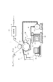
- FIG. 1 is a diagram schematically showing a wrapping paper manufacturing apparatus 1 that manufactures a low spread fired wrapping paper.
- the wrapping paper manufacturing apparatus 1 includes a travel path 24 of a web W made of paper, and the travel path 24 extends from a feeding reel of the web W toward a take-up reel. After the web W fed out from the feed reel travels along the travel path 24, the finished product is wound as a web Q on the take-up reel to form an original roll.
- a coating device 26 is disposed on the travel route 24.
- the coating device 26 includes a supply tank 22.
- a combustion suppression liquid LQ is stored as a liquid to be applied to the web W as an object to be processed.
- the supply tank 22 is mounted on a weighing scale 28.
- the weighing scale 28 detects the weight of the supply tank 22, that is, the remaining amount of the combustion suppression liquid LQ, and the detection result functions as a control means.
- the monitoring device 30 includes, for example, a display, and it is desirable to display the remaining amount of the combustion suppressing liquid in the supply tank 22, that is, the consumption amount on the display based on the detection result.
- the combustion suppression liquid can be obtained by dissolving a powder of a combustion inhibitor in soft water.
- a combustion inhibitor for example, sodium alginate or pectin can be used as the combustion inhibitor, and the soft water used in the combustion inhibitor liquid is substantially free of mineral ions such as calcium ions (Ca2 +) and magnesium ions (Ma2 +). desirable.
- the mineral ion concentration in soft water is preferably 0 to 1 mg / l.
- the combustion inhibitor in the combustion suppression liquid is, for example, pectin
- the viscosity of the combustion suppression liquid is, for example, 30 to 4000 (mPa ⁇ s), which is relatively compared to water or the like. It shows a high viscosity.
- the coating device 26 further includes a press roll 32 and a gravure roll 34.
- the press roll 32 and the gravure roll 34 are disposed with the traveling path 24, that is, the web W interposed therebetween, and can be rotated in opposite directions.
- the gravure roll 34 has a large number of transfer areas capable of holding the combustion-suppressing liquid on the outer peripheral surface thereof, and these transfer areas have a predetermined direction in the circumferential direction of the gravure roll 34 in order to periodically form the band described above on the web W. Arranged at intervals.
- a finisher roll 36 is in rolling contact with the outer peripheral surface of the gravure roll 34, and a nozzle 38 is disposed above the finisher roll 36.
- the nozzle 38 is connected to the supply tank 22 via a supply line 40, and a displacement pump 42 is disposed in the supply line 40, and a nozzle 38 is attached to the other end side of the displacement pump 42. .
- the tip of the nozzle 38 faces the gravure roll 34. Therefore, when the pump 42 is driven, the combustion suppression liquid LQ in the supply tank 22 is sent to the nozzle 38 via the supply line 40, and the nozzle 38 supplies the combustion suppression liquid LQ to the outer peripheral surface of the gravure roll 34. .
- a removing device 44 for removing excess combustion suppression liquid from the outer peripheral surface is disposed.
- the removing device 44 includes a doctor blade 45, and the doctor blade 45 has a tip that is in sliding contact with the outer peripheral surface of the gravure roll 34.
- the removing device 44 includes a collection chute 60.
- the recovery chute 60 covers the area below the gravure roll 34, that is, from the lower end of the doctor blade 45 to the finisher roll 36 through the gravure roll 34, and returns the combustion suppression liquid LQ to the supply tank 22. is there.
- a dryer 62 is disposed downstream of the press roll 32 and the gravure roll 34 in the traveling path 24. When the web W passes through the dryer 62, the dryer 62 dries the web W.
- FIG. 2 is an enlarged perspective view showing the solid-liquid separation device 10 and its peripheral configuration in more detail, and the same parts as those in FIG. 1 are denoted by the same reference numerals.
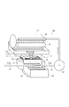
- FIG. 3 is a plan view showing the solid-liquid separator 10, and FIG. 4 is a view showing a configuration on the side thereof. Further, FIG. 5 is a view showing the supply tank 22 and the solid-liquid separation device 10 thereon.
- the solid-liquid separation device 10 is configured to include a slit plate 11 as a separation plate for separating a solid component, and a scraper 13 that slides on the slit plate.
- the slit plate 11 includes a plurality of long constituent members 11a, 11a,... Arranged at equal intervals with an interval Wt.
- the slit plate 11 is designed to separate and filter a solid component SM larger than the interval Wt. .
- the constituent member 11a is long and maintains a constant space between each other, it may be in the shape of a rod or an elongated strip.
- the slit plate 11 illustrated here is provided with a falling portion 11ED (refer to a part indicated by an arrow AR in FIGS. 2 and 4) in which the constituent member 11a is bent downward at both ends.
- a falling portion 11ED (refer to a part indicated by an arrow AR in FIGS. 2 and 4) in which the constituent member 11a is bent downward at both ends. The merit of such a structure will be described later.
- the scraper 13 is arranged to reciprocate between one end and the other end while sliding on the slit plate 11 on the slit plate 11 along the longitudinal direction LD of the constituent member 11a.
- solid content receiving tanks hereinafter referred to as recovery tanks 19 for receiving the solid content SM discharged by the scraper 13 are installed.
- recovery tanks solid content receiving tanks
- a pair of side walls 11WA are arranged in the width direction WD of the slit plate 11 at the front and rear thereof.
- the slit plate 11 receives the combustion suppression liquid LQ between the side walls 11WA, and separates the solid content SM by the constituent members 11a, 11a, as described above.
- the solid portion SM delivered from both ends of the slit plate 11 is received by the recovery tank 19.
- the slit plate 11 is formed in a curved shape that protrudes downward in the direction in which the scraper 13 reciprocates (that is, the longitudinal direction LD).
- the scraper 13 dispenses the solid content SM while moving along the curved surface of the slit plate 11.
- the scraper 13 includes a scraper moving mechanism that holds the scraper 13 and allows the scraper 13 to move up and down along the reciprocating movement and the curve.
- Such a scraper moving mechanism includes a moving body that linearly reciprocates the side portion of the slit plate 11. When the scraper 13 is moved by this moving body, the scraper moving mechanism can be moved along the curved surface of the slit plate 11. It is only necessary to have a mechanism that can do this.
- the scraper 13 is placed, and the vicinity of the side of the slit plate 11 is horizontally disposed, and the linear slider 14 (moving body) capable of reciprocating within the range from one end to the other end of the slit plate 11 and the scraper 13 are supported.
- the linear slider 14 moving body
- it is configured to include a support structure 16 that allows vertical movement along the curvature of the slit plate 11.
- the linear slider 14 moves along a linear guide rail 15 disposed on the side of the slit plate 11.
- a support structure 16 that allows the scraper 13 to move up and down along the curved surface of the slit plate 11 is provided on the slider body 14.
- the scraper 13 is provided with a shaft end portion 13TP that projects back and forth in the width direction WD perpendicular to the longitudinal direction LD.
- the support structure 16 provided on the linear slider 14 has a support column 16a that supports the shaft end portion 13TP as a base portion and is divided into two support portions 16b on the upper side, and a shaft end portion therebetween. 13TP can be moved up and down and received.
- the height of the support portion 16b is set to a length that allows the scraper 13 to move up and down in accordance with the curvature of the slit plate 11. And as shown in FIG. 5, the support structure 16 is arrange
- the two support structures 16 are connected by a connecting member 16CN under the slit plate 11.
- the linear slider 14 itself can have a simple structure that reciprocates on the linear guide rail 15.
- the guide rail 15 may be a rack member
- the moving body may be mounted with a motor on which a pitch-on gear that meshes with the rack member is mounted on the drive shaft on the linear slider 14 side.
- the support structure 16 as mentioned above is provided in this moving body. Accordingly, it is possible to realize a scraper moving mechanism in which the support structure 16 moves with the moving body, and as a result, the scraper 13 moves along the curved surface of the slit plate 11.
- the scraper 13 shown in the figure has comb teeth 13a (see FIG. 4) inserted between the constituent members 11a, 11a,. Therefore, when the scraper 13 is moved, not only the upper surface of the slit plate 11 but also between the constituent members 11a constituting the same can be cleaned. As a result, the interval Wt between the constituent members 11a can be maintained without clogging, so that solid-liquid separation can be performed smoothly and continuously.
- the solid-liquid separation device 10 is provided with a lift prevention mechanism that moves on the slit plate 11 while preventing the scraper 13 from floating.
- the lift prevention mechanism can be realized by the long hole 11HL provided in the side wall 11WA.
- the long hole 11HL is curved in accordance with the curved slit plate 11 convex downward, and receives the shaft end portion 13TP of the scraper 13. Therefore, the range in which the long hole 11HL moves the scraper 13 is defined.
- the upper hole 11HL restricts the upper position of the scraper 13 that is allowed to move up and down on the support structure 16, so that it can be prevented from rising.
- the long hole 11HL is an example of an ascent prevention mechanism.
- a structure in which a contraction spring is disposed between the shaft end portion 13TP and the linear slider 14 and the shaft end portion 13TP is biased toward the linear slider 14 may be employed.
- the solid-liquid separator 10 is provided with a discharge assist mechanism for more reliably discharging the solid content SM with the scraper 13.
- the side surface shape (transverse cross-sectional shape) of the scraper 13 is preferably a divergent shape in which the lower side is widened. In the present embodiment, it is generally triangular, but may be trapezoidal.
- the individual SM can be paid out smoothly by the form of widening at the bottom.
- Comb teeth 13a are provided at the lower end.
- the shaft end portion 13TP protrudes in the width direction from the vicinity of the apex 13SU on the upper side of the triangle, and the shaft end portion 13TP is supported by the support structure 16 as described above.
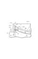
- FIG. 6 is a diagram schematically showing a state where the scraper 13 moves on the slit plate 11 and reaches the end.
- the scraper 13 that has reached the end portion is inclined at an increased angle so that the inclined surface 13FA hits the stopper 11ST and the inclined surface 13FA slides down the solid content SM (shake the head around 13TP). ).
- the solid content SM on the slope 13FA can be promoted to fall into the collection tank 19 to assist the dispensing.
- the slit plate 11 as the separation plate has a curved shape that protrudes downward, and the side surface shape (cross-sectional shape) of the scraper 13 is a divergent shape in which the lower side is widened, the scraper 13 is the end of the separation plate. Since the slope 13FA faces upward when reaching the position, such a payout assist mechanism can be used particularly preferably.
- the slit plate 11 is formed of a material such as stainless steel, for example, it is preferable because it is not rusted and is smooth.
- the interval Wt between the constituent members 11a and 11a constituting the slit plate may be appropriately determined according to the solid content SM to be separated, but the solid-liquid separation applied to the wrapping paper manufacturing apparatus 1 illustrated here. In the case of the apparatus 10, the interval Wt is preferably 1.5 to 5.0 mm. Further, the curvature of curvature preferably employed in the slit plate 11 is, for example, 1/400 mm to 1/800 mm. With such a curve, the solid content SM generated in the liquid can be efficiently separated by smoothly moving the scraper 13 along the curved surface while preventing the mucus from overflowing.
- a material preferably employed in the scraper 13 that slides on the slit plate 11 is a resin material.
- the resin material is suitable as a raw material for the scraper 13 because its surface is flat and lubricious, lightweight and durable.
- a preferable resin material is a resin material called engineering plastics such as ultra high density polyethylene, PEEK, 66 nylon and the like.
- the slit plate has a curved shape that protrudes downward, and the scraper 13 is slid on the slit plate.
- Solid-liquid separation since the recovery tank 19 that recovers the solid matter discharged to the outside of the slit plate 11 is installed in the direction in which the scraper 13 reciprocates, it can be recovered without contaminating the surroundings.
- the scraper 13 provided with the comb teeth 13a inserted between the constituent members 11a of the slit plate 11 is provided at both ends of the slit plate 11 as described above. It can be swept out without clogging the solid matter that has entered between when moving to the section.
- the wrapping paper manufacturing apparatus 1 exemplified here is configured such that the weight of the collection tank 19 and the supply tank 22 is measured by the above-described weigh scale 28. Thereby, since the weight reduced with the weight scale 28 can be estimated as the combustion suppression liquid LQ applied to the web W, the coating amount can be managed. Then, when the combustion suppression liquid LQ decreases by a predetermined amount or more, the combustion suppression liquid LQ may be replenished so as to compensate for the shortage.
- FIG. 5 shows a preferred configuration example as the supply tank 22 arranged in the solid-liquid separation device 10 in the wrapping paper manufacturing apparatus 1.
- the inside of the supply tank 22 sends out a combustion suppression liquid LQ, and receives a new (fresh) combustion suppression liquid LQ from an external tank (not shown) via a supply line 46, and a solid-liquid separator.
- a return tank 22RE for receiving the combustion suppression liquid LQ that has returned through 10.
- the main tank 22MA is provided with a delivery port 40E of the supply line 40 to the wrapping paper manufacturing apparatus 1, and a new combustion suppression liquid LQ (fresh coating) is supplied from a supply line 46 that supplies the combustion suppression liquid LQ that is insufficient due to use.
- a discharge port 46U for placing the working fluid is disposed.
- a return tank 22RE is arranged adjacent to the main tank 22MA.
- the return tank 22RE is filled with a combustion suppression liquid LQ that is separated and filtered by the solid-liquid separator 10 positioned above and circulated.
- the main tank 22MA and the return tank 22RE are partitioned by a punching metal plate 23 in which a number of punch holes 23h are formed (may be partitioned by a wire mesh or the like). Therefore, the return combustion suppression liquid LQ that has entered the return tank 22RE is circulated from the delivery port 40E to the coating device 26 via the punching metal plate 23 and the main tank 22MA.
- the punching metal plate 23 is disposed as a filter member for preventing the solid material from being circulated when some solid matter is mixed in the returned combustion suppression liquid LQ.
- FIG. 7 is a block diagram illustrating an example of a configuration relating to the control of the above-described wrapping paper manufacturing apparatus 1.
- the solid-liquid separator 10 described above and a coating device 26 are included as liquid processing means for processing the web.
- the monitoring device 30 realizes a liquid management means for managing the change in weight of the liquid, a control means for controlling the solid-liquid separation device 10 and the coating device 26 as a whole.
- such a monitoring apparatus 30 is also provided with memory
- the storage device stores control programs and data used for the wrapping paper manufacturing apparatus 1.
- the monitoring device 30 when functioning as a liquid management means receives an output signal from the weigh scale 28 and confirms the coating amount.
- an external tank (not shown) is used.
- a new combustion suppression liquid is replenished via the pipe 46.
- the monitoring apparatus 30 outputs the drive signal to the said solid-liquid separator 10, and performs the cooperative control which drives the said scraper at the timing which replenishes the combustion suppression liquid (liquid) LQ which was insufficient in this way.
- the solid-liquid separation apparatus 10 is driven in accordance with the replenishment of the combustion suppression liquid. That is, the scraper 13 operates in accordance with the timing of replenishing the combustion suppression liquid.
- the scraper 13 When the scraper 13 is operated, there is a concern that vibrations and the like may occur, which may affect the weighing scale 28 that measures the combustion suppression liquid.
- the weight fluctuates, so that it is not suitable for collecting data for managing the combustion suppression liquid.
- the solid-liquid separation device 10 is driven only when the liquid management data collection is stopped in order to replenish the combustion suppression liquid, and when there is a possibility of data collection, the solid-liquid separation is performed.
- the apparatus 10 Since the apparatus 10 is not driven, it is always possible to collect highly accurate data and use it for apparatus control. Further, as described above, the weighing scale 28 serving as a weighing unit calculates the weight of the collected material in the collection tank 19 together with the combustion suppression liquid in the supply tank 22 and manages the change in the weight of the monitoring device 30. Therefore, the combustion suppression liquid consumed by the coating apparatus 26 can be easily confirmed, and the low-flammability wrapping paper can be manufactured efficiently.
- the above description limits the drive timing of the scraper 13 in consideration of the occurrence of vibration or the like when the scraper 13 operates. However, this is not necessary if the vibration of the scraper 13 does not cause a problem.
- the monitoring device 30 (control means) may be driven at a constant timing (for example, every predetermined time).
- the present invention is not limited to the above-described embodiments, and various modifications can be made.
- the preferred example in which the solid-liquid separation device according to the present invention is applied to a low-rollability wrapping paper manufacturing apparatus has been described.
- the solid-liquid separation device according to the present invention can be similarly applied to devices other than the above-described low-flammability wrapping paper manufacturing device that generate an unnecessary solid component when processing an object to be processed using a liquid.
- the slit plate is illustrated as a preferable example of the separation plate.
- the slit plate is not limited to this, and includes a large number of openings and meshes that allow only liquid to pass and prevent solids from passing.
- a curved plate-like member that can be separated from the solid component can be appropriately employed.
Landscapes
- Chemical & Material Sciences (AREA)
- Chemical Kinetics & Catalysis (AREA)
- Paper (AREA)
Description
本発明は、被処理物の処理に用いる液体と、この液体中に生じた不要な固体状の成分(以下、固体分と称す)を分離する固液分離装置に関する。この固液分離装置は、例えばシガレットに低延焼性を付与する低延焼性巻紙を製造する工程などにおいて、好適に適用される。
近年、シガレットに使用される低延焼性巻紙が知られており、この巻紙には所定領域に燃焼抑制剤が塗工されている。この低延焼性巻紙を用いたシガレットを着火すると、その基端側への延焼が低減する。詳しくは、低延焼性巻紙は、紙製で帯状であるウエブの長手方向に対して所定間隔を存して液状の燃焼抑制剤を幅方向に横断するように(バンド状に)塗工し、その後、これを乾燥して得られる(特許文献1参照)。
上記のような低延焼性巻紙を製造するシステムでは、巻紙への塗工により減少した燃焼抑制剤(塗工用の液体)を補充しながら循環させて使用する形態が採用されている。ところが、ここで使用される燃焼抑制剤は粘度の高い液体であり、また巻紙には填料として炭酸カルシウムなどの無機物が含まれているので、燃焼抑制剤を循環させている間に、「ゲル状物質」が発生する場合がある。この「ゲル状物質」は、炭酸カルシウムから生成したカルシウムイオン等と燃焼抑制剤の主成分とが反応してゲル状化したものである。このような「ゲル状物質」が低延焼性巻紙を製造するシステム内を循環すると、循環経路の途中で目詰まりして製造トラブルの原因となる。そこで、例えば上記で例示した「ゲル状物質」の様な固体状の成分(以下、固体分と称す)と粘度を有する上記燃焼抑制材とを効率良く除去できる固液分離装置、この固液分離装置を用いた液処理システムへの要請がある。
上述の要請は、液体中に生じた不要な固体分を分離する固液分離装置であって、
前記固体分を分離する分離板と、前記分離板の上を摺動しつつ往復移動して、当該分離板の外側へ前記固体分を払い出すスクレーパとを備えており、
前記スクレーパの前記往復移動の方向にて、前記分離板は下向きに凸となる湾曲した形状に形成されている、ことを特徴とする固液分離装置により達成できる。
前記固体分を分離する分離板と、前記分離板の上を摺動しつつ往復移動して、当該分離板の外側へ前記固体分を払い出すスクレーパとを備えており、
前記スクレーパの前記往復移動の方向にて、前記分離板は下向きに凸となる湾曲した形状に形成されている、ことを特徴とする固液分離装置により達成できる。
そして、前記分離板は、長尺の構成部材を複数、等間隔に配置し、前記間隔よりも大きな前記固体分を分離するスリット板であり、前記スクレーパは、前記スリット板を構成する前記構成部材の間それぞれに挿入される櫛歯状の先端部を有しているのが望ましい。
また、前記スクレーパを保持し、前記往復移動および前記湾曲に沿って上下移動することを許容するスクレーパ移動機構を含んでいる構成を採用できる。
また、前記スクレーパが移動する際に浮上るのを防止する浮上り防止機構を更に備えているのが望ましい。
そして、前記スクレーパによる前記固体分の払い出し動作を補助する払出し補助機構を更に備えているのがより望ましい。
そして、前記スクレーパによる前記固体分の払い出し動作を補助する払出し補助機構を更に備えているのがより望ましい。
そして、上記要請は、上記における何れかに記載の固液分離装置と、前記液体を用いて被処理物を処理する液処理手段と、前記液体の重量変化を管理する液管理手段と、これら全体を制御する制御手段とを備えてなる液処理システムであって、
前記制御手段は、前記液管理手段が前記液体を補充するときに応じて、前記固液分離装置の前記スクレーパを駆動させる協調制御を実行する、ことを特徴とする液処理システムによって達成できる。
前記制御手段は、前記液管理手段が前記液体を補充するときに応じて、前記固液分離装置の前記スクレーパを駆動させる協調制御を実行する、ことを特徴とする液処理システムによって達成できる。
また、前記分離板の外側近傍に設置した、前記スクレーパにより払出された前記固体分を回収する固体分受けタンクを含み、前記固体分受けタンク内の回収物の重量を含めて当該液処理システム内の前記液体を計測する計量手段を更に有し、前記液管理手段は、前記計量手段からの出力に基づいて前記液体の重量変化の管理をするようにしてもよい。
前記液処理システムはシガレットの巻紙製造装置を含み、
前記液処理手段は、紙製で帯状であるシガレット用のウエブを前記被処理物として、前記液体として燃焼抑制液を塗工する塗工装置を、含むものとすることができる。
そして、この場合、前記液体は、粘度が30~4000(mPa・s)の燃焼抑制液とするのが好ましい。
前記液処理手段は、紙製で帯状であるシガレット用のウエブを前記被処理物として、前記液体として燃焼抑制液を塗工する塗工装置を、含むものとすることができる。
そして、この場合、前記液体は、粘度が30~4000(mPa・s)の燃焼抑制液とするのが好ましい。
また、上記要請は、上記における何れかに記載の固液分離装置と、前記液体を用いて被処理物を処理する液処理手段と、前記液体の重量変化を管理する液管理手段と、これら全体を制御する制御手段とを備えてなる液処理システムであって、
前記制御手段は、一定のタイミングで、前記固液分離装置の前記スクレーパを駆動させる協調制御を実行する、ことを特徴とする液処理システムによっても達成できる。
前記制御手段は、一定のタイミングで、前記固液分離装置の前記スクレーパを駆動させる協調制御を実行する、ことを特徴とする液処理システムによっても達成できる。
本発明の固液分離装置によれば、例えば上記「ゲル状物質」の様な固体と粘度を有する上記燃焼抑制材とを効率良く除去できる固液分離装置、またこの固液分離装置を用いた液処理システム、が提供される。
以下、本発明に係る一実施形態を、図を参照して説明する。ここで例示の実施形態は、固液分離装置を、低延焼性巻紙の製造装置に適用する場合である。そして、低延焼性巻紙の製造装置は、燃焼抑制液を用いて巻紙を処理する(塗液を塗工する)ものであり、液処理システムの一形態と理解される。
以下では、まず、低延焼性巻紙の製造装置の概略を説明してから、これに適用されている固液分離装置について詳述する。
以下では、まず、低延焼性巻紙の製造装置の概略を説明してから、これに適用されている固液分離装置について詳述する。
図1は低延焼性巻紙を製造する巻紙製造装置1を概略的に示した図である。
巻紙製造装置1は紙製で帯状であるウエブWの走行経路24を備え、この走行経路24はウエブWの繰出リールから巻取リールに向けて延びている。繰出リールから繰出されたウエブWは走行経路24に沿って走行した後、完成したものは巻紙Qとして巻取リールに巻き取られ、原反ロールが形成される。
巻紙製造装置1は紙製で帯状であるウエブWの走行経路24を備え、この走行経路24はウエブWの繰出リールから巻取リールに向けて延びている。繰出リールから繰出されたウエブWは走行経路24に沿って走行した後、完成したものは巻紙Qとして巻取リールに巻き取られ、原反ロールが形成される。
走行経路24には塗工装置26が配置されている。この塗工装置26は供給タンク22を備えている。この供給タンク22内には、被処理物としてのウエブWに塗工する液体として燃焼抑制液LQが蓄えられている。供給タンク22は重量計28上に載せられており、この重量計28は供給タンク22の重量、即ち、燃焼抑制液LQの残量を検出しており、その検出結果を制御手段として機能する監視装置30に送信している。この監視装置30は例えばディスプレイを含み、前記検出結果に基づき、ディスプレイに供給タンク22内の燃焼抑制液の残量、即ち、消費量を表示するようにしておくのが望ましい。
上記燃焼抑制液は、軟水に燃焼抑制剤の粉末を溶解させて得ることができる。燃焼抑制剤には例えばアルギン酸ナトリウム又はペクチンを使用でき、また、燃焼抑制液に使用される軟水は、カルシウムイオン(Ca2+)及びマグネシウムイオン(Ma2+)等のミネラルイオンを実質的に含んでいないものが望ましい。軟水中のミネラルイオン濃度は0~1mg/lであるのが好ましい。なお、燃焼抑制液の生成には軟水に代えて純水を使用することも可能である。
本実施例の場合、燃焼抑制液中の燃焼抑制剤は、例えばペクチンであり、燃焼抑制液の粘度は例えば粘度が30~4000(mPa・s)であり、水などと比較して相対的に高い粘度を示すものである。
本実施例の場合、燃焼抑制液中の燃焼抑制剤は、例えばペクチンであり、燃焼抑制液の粘度は例えば粘度が30~4000(mPa・s)であり、水などと比較して相対的に高い粘度を示すものである。
塗工装置26はプレスロール32及びグラビアロール34を更に含んでいる。これらプレスロール32及びグラビアロール34は走行経路24、即ち、ウエブWを挟んで配置され、互いに逆向きに回転可能である。グラビアロール34はその外周面に燃焼抑制液を保持可能な多数の転写区域を有し、これら転写区域はウエブWに前述したバンドを周期的に形成すべく、グラビアロール34の周方向に所定の間隔を存して配置されている。
グラビアロール34の外周面にはファニッシャロール36が転接されており、このファニッシャロール36の上方にはノズル38が配置されている。このノズル38は供給管路40を介して供給タンク22に接続されており、供給管路40には容量式ポンプ42が配置され、容量式ポンプ42の他端側にはノズル38が取付けてある。ノズル38の先端は、グラビアロール34に向けてある。従って、ポンプ42が駆動されたとき、供給タンク22内の燃焼抑制液LQは供給管路40を介してノズル38に送出され、ノズル38は燃焼抑制液LQをグラビアロール34の外周面に供給する。
また、グラビアロール34の近傍には、その外周面から余剰の燃焼抑制液を除去する除去装置44が配置されている。この除去装置44はドクタブレード45を含み、このドクタブレード45は、グラビアロール34の外周面に相対的に摺接する先端を有している。
更に、除去装置44は回収シュート60を備えている。この回収シュート60はグラビアロール34の下方、即ち、ドクタブレード45の先端部からグラビアロール34を経てファニッシャロール36に至る領域を下方から覆い、燃焼抑制液LQを供給タンク22へ戻すようにしてある。
更に、走行経路24にはプレスロール32及びグラビアロール34の下流に乾燥器62が配置されている。ウエブWが乾燥器62を通過する際、乾燥器62はウエブWを乾燥する。
更に、走行経路24にはプレスロール32及びグラビアロール34の下流に乾燥器62が配置されている。ウエブWが乾燥器62を通過する際、乾燥器62はウエブWを乾燥する。
そして、この巻紙製造装置1では固液分離装置10(図1では、簡略して、その位置だけを示している)が回収シュート60と供給タンク22との間に配置されている。固液分離装置10は、回収シュート60から燃焼抑制液LQを受けて、その液中の固体分を分離ろ過した燃焼抑制液LQを、下に位置する供給タンク22へと戻している。
図2は、固液分離装置10およびその周辺構成を拡大して、より詳細に示した斜視図であり、図1と同じ部位には同一符号を付してある。また、図3はこの固液分離装置10について示した平面図であり、図4はその側面での構成を示した図である。更に、図5は供給タンク22と、その上の固液分離装置10とを示した図である。
図2は、固液分離装置10およびその周辺構成を拡大して、より詳細に示した斜視図であり、図1と同じ部位には同一符号を付してある。また、図3はこの固液分離装置10について示した平面図であり、図4はその側面での構成を示した図である。更に、図5は供給タンク22と、その上の固液分離装置10とを示した図である。
図3、4で示すように、固液分離装置10は、固体分を分離する分離板としてのスリット板11と、スリット板の上を摺動するスクレーパ13を含んで構成されている。スリット板11は、長尺の構成部材11a、11a・・を複数、間隔Wtをもって等間隔に配置してあり、この間隔Wtよりも大きな固体分SMを分離し、ろ過するように設計してある。構成部材11aは長尺で、互いの間に存する空間を一定に維持したものであれば、棒形状でも、細長い帯形状などでもよい。
なお、ここで例示しているスリット板11は、構成部材11aが両端部で下向きに折り曲げられた立下げ部11ED(図2、および図4にて矢印ARで示す部分参照)が設けてある。このような構造としたメリットについては後述する。
なお、ここで例示しているスリット板11は、構成部材11aが両端部で下向きに折り曲げられた立下げ部11ED(図2、および図4にて矢印ARで示す部分参照)が設けてある。このような構造としたメリットについては後述する。
そして、スクレーパ13は、上記スリット板11上を構成部材11aの長手方向LDに沿って、スリット板11上を摺動しつつ一端から他端の間で往復移動するように配置してある。長手方向LDでのスリット板11の両外側には、スクレーパ13によって払出される固体分SMを受ける固体分受けタンク(以下、回収タンク)19が設置してある。
また、スリット板11の幅方向WDで、その前後に一対の側壁11WAが配置してある。スリット板11は、この側壁11WA間にて燃焼抑制液LQを受入れつつ、上記のように構成部材11a、11a・・・で固体分SMを分離する。そして、長手方向LDには、スリット板11の両端から払出される固体分SMを回収タンク19で受取るようにしてある。
なお、払出される固体分SMが回収タンク19に確実に収納されるように、両側部にガイド板やガイドシュートなどを配置しておくのがより好ましい。
また、スリット板11の幅方向WDで、その前後に一対の側壁11WAが配置してある。スリット板11は、この側壁11WA間にて燃焼抑制液LQを受入れつつ、上記のように構成部材11a、11a・・・で固体分SMを分離する。そして、長手方向LDには、スリット板11の両端から払出される固体分SMを回収タンク19で受取るようにしてある。
なお、払出される固体分SMが回収タンク19に確実に収納されるように、両側部にガイド板やガイドシュートなどを配置しておくのがより好ましい。
上記スリット板11は、スクレーパ13の往復移動する方向(すなわち、長手方向LD)にて下向きに凸となる湾曲した形状に形成されている。
そして、前記スクレーパ13はスリット板11の湾曲面に沿って移動しつつ固体分SMを払出す。図5も参照して説明すると、スクレーパ13を保持し、前記往復移動および前記湾曲に沿って上下移動することを許容するスクレーパ移動機構を含んでいる。このようなスクレーパ移動機構は、スリット板11の側部を直線的に往復移動する移動体を含み、この移動体でスクレーパ13を移動したときに、スリット板11の曲面に沿って移動させることができる機構を備えていればよい。
例示では、スクレーパ13が載置されスリット板11の側部近傍を水平に、そしてスリット板11の一端から他端の範囲内を往復移動可能なリニアスライダ14(移動体)と、スクレーパ13を支持しつつスリット板11の湾曲に沿って上下移動することを許容する支持構造16とを含んで構成されている。
そして、前記スクレーパ13はスリット板11の湾曲面に沿って移動しつつ固体分SMを払出す。図5も参照して説明すると、スクレーパ13を保持し、前記往復移動および前記湾曲に沿って上下移動することを許容するスクレーパ移動機構を含んでいる。このようなスクレーパ移動機構は、スリット板11の側部を直線的に往復移動する移動体を含み、この移動体でスクレーパ13を移動したときに、スリット板11の曲面に沿って移動させることができる機構を備えていればよい。
例示では、スクレーパ13が載置されスリット板11の側部近傍を水平に、そしてスリット板11の一端から他端の範囲内を往復移動可能なリニアスライダ14(移動体)と、スクレーパ13を支持しつつスリット板11の湾曲に沿って上下移動することを許容する支持構造16とを含んで構成されている。
より詳細には、リニアスライダ14はスリット板11の側部に配置した直線状の案内レール15に沿って移動する。このスライダボディ14上に、スリット板11の湾曲面に沿ってスクレーパ13の上下動を許容する支持構造16が設けてある。
例示の構造では、スクレーパ13には長手方向LDに垂直な幅方向WDで前後に突出した軸端部13TPが設けてある。一方、リニアスライダ14上に設けた支持構造16は、前記軸端部13TPを支持する支持柱16aを基部として、上側は2つに先割させ支持部16bとされており、その間に軸端部13TPを上下動自在にして受けるようにしてある。支持部16bの高さは、スリット板11の湾曲に応じ、にスクレーパ13が上下動できる範囲の長さに設定してある。
そして、図5で示しているように、スリット板11を間に挟んで両側に支持構造16が配置されて、スクレーパ13の軸端部13TPを支持している。2つの支持構造16は、スリット板11下の連結部材16CNで接続されている。
例示の構造では、スクレーパ13には長手方向LDに垂直な幅方向WDで前後に突出した軸端部13TPが設けてある。一方、リニアスライダ14上に設けた支持構造16は、前記軸端部13TPを支持する支持柱16aを基部として、上側は2つに先割させ支持部16bとされており、その間に軸端部13TPを上下動自在にして受けるようにしてある。支持部16bの高さは、スリット板11の湾曲に応じ、にスクレーパ13が上下動できる範囲の長さに設定してある。
そして、図5で示しているように、スリット板11を間に挟んで両側に支持構造16が配置されて、スクレーパ13の軸端部13TPを支持している。2つの支持構造16は、スリット板11下の連結部材16CNで接続されている。
よって、リニアスライダ14自体は直線状である案内レール15上を往復動するという簡単な構造にできる。例えば案内レール15をラック部材とし、リニアスライダ14側に前記ラック部材と噛合するピッチオンギアを駆動軸に装着したモータを搭載した移動体とすることができる。
そして、この移動体に前述のような支持構造16を設けてある。これにより、支持構造16が移動体に伴って移動し、その結果としてスクレーパ13がスリット板11の湾曲面に沿って移動するというスクレーパ移動機構を実現できる。
そして、この移動体に前述のような支持構造16を設けてある。これにより、支持構造16が移動体に伴って移動し、その結果としてスクレーパ13がスリット板11の湾曲面に沿って移動するというスクレーパ移動機構を実現できる。
さらに、図示してあるスクレーパ13は、スリット板11を構成する構成部材11a、11a・・・の間に挿入される櫛歯13a(図4参照)を先端部に備えている。よって、スクレーパ13が移動したときにスリット板11の上面だけでなく、これを構成する構成部材11aの間も清掃できる。これにより構成部材11a間の間隔Wtを詰まり無く維持できるので、固液分離を円滑に継続実行できる。
更に、上記スクレーパ13を円滑に移動させる好適な構造について説明する。固液分離装置10は、スクレーパ13の浮上りを防止しつつスリット板11上を移動させる浮上り防止機構が設けてある。
図4を参照して、例示した浮上り防止機構を説明する。浮上り防止機構は、前述した側壁11WAに設けた長穴11HLにより実現できる。この長穴11HLは下向きに凸となる湾曲しているスリット板11に応じて湾曲しており、スクレーパ13の軸端部13TPを受入れる。よって、長穴11HLがスクレーパ13の移動する範囲を規定する。そして、支持構造16上では上下動が許容されているスクレーパ13の上部位置を、長穴11HLが規制するので浮上りを防止できる
なお、上記長穴11HLは上り防止機構の一例である。例えば軸端部13TPとリニアスライダ14との間に収縮バネを配置して、軸端部13TPをリニアスライダ14側に付勢するような構造など採用してもよい。
図4を参照して、例示した浮上り防止機構を説明する。浮上り防止機構は、前述した側壁11WAに設けた長穴11HLにより実現できる。この長穴11HLは下向きに凸となる湾曲しているスリット板11に応じて湾曲しており、スクレーパ13の軸端部13TPを受入れる。よって、長穴11HLがスクレーパ13の移動する範囲を規定する。そして、支持構造16上では上下動が許容されているスクレーパ13の上部位置を、長穴11HLが規制するので浮上りを防止できる
なお、上記長穴11HLは上り防止機構の一例である。例えば軸端部13TPとリニアスライダ14との間に収縮バネを配置して、軸端部13TPをリニアスライダ14側に付勢するような構造など採用してもよい。
また固液分離装置10には、上記スクレーパ13で固体分SMをより確実に払い出すための払出し補助機構が付加してある。
図4等で示すように、スクレーパ13の側面形状(横断面形状)は下側が広くなる末広がりの形態が好ましく、本実施形態では概ね三角形形状であるが台形などでもよい。下側が広くなる末広がりの形態によって円滑に個体分SMを払い出すことが出来る。下端には櫛歯13aが設けてある。そして、三角形上側の頂点13SU近傍から幅方向に軸端部13TPが突出しており、前述したように、軸端部13TPが支持構造16で支持されている。
スクレーパ13がスリット板11上を摺動したときには三角形の両側の辺(長手方向LDで見て、両側の斜面13FA、図4参照)によって燃焼抑制液LQ内の不要な固体分SMが外側へと払い出される。
この動作の繰り返しで、斜面となる斜面13FAに固体分SMが乗り上がるので、リット板11の端部に来たとき、固体分SMを滑り落とすようにするのが望ましい。そこで、ここでは上記軸端部13TPより下側の斜面13FAの少なくとも一部に、当接するストッパ11STが上記側壁11WAの端部の内側に設けてある。
図6はスクレーパ13がスリット板11上を移動して端部まできたときの様子を模式的に示した図である。この図6で示すように、端部に到達したスクレーパ13は斜面13FAがストッパ11STに当って、この斜面13FAが固体分SMを滑り落とすよう角度を増して傾斜する(13TPを中心に首を振る)。この動作により斜面13FA上の固体分SMが回収タンク19へ落下するのを促進して払出補助を行える。分離板としてのスリット板11が下向きに凸となる湾曲した形状であり、スクレーパ13の側面形状(横断面形状)が、下側が広くなる末広がりの形態である場合、スクレーパー13が分離板の端部に到達したときには斜面13FAが上を向くことになるのでこのような払出し補助機構を特に好適に用いることが出来る。
図4等で示すように、スクレーパ13の側面形状(横断面形状)は下側が広くなる末広がりの形態が好ましく、本実施形態では概ね三角形形状であるが台形などでもよい。下側が広くなる末広がりの形態によって円滑に個体分SMを払い出すことが出来る。下端には櫛歯13aが設けてある。そして、三角形上側の頂点13SU近傍から幅方向に軸端部13TPが突出しており、前述したように、軸端部13TPが支持構造16で支持されている。
スクレーパ13がスリット板11上を摺動したときには三角形の両側の辺(長手方向LDで見て、両側の斜面13FA、図4参照)によって燃焼抑制液LQ内の不要な固体分SMが外側へと払い出される。
この動作の繰り返しで、斜面となる斜面13FAに固体分SMが乗り上がるので、リット板11の端部に来たとき、固体分SMを滑り落とすようにするのが望ましい。そこで、ここでは上記軸端部13TPより下側の斜面13FAの少なくとも一部に、当接するストッパ11STが上記側壁11WAの端部の内側に設けてある。
図6はスクレーパ13がスリット板11上を移動して端部まできたときの様子を模式的に示した図である。この図6で示すように、端部に到達したスクレーパ13は斜面13FAがストッパ11STに当って、この斜面13FAが固体分SMを滑り落とすよう角度を増して傾斜する(13TPを中心に首を振る)。この動作により斜面13FA上の固体分SMが回収タンク19へ落下するのを促進して払出補助を行える。分離板としてのスリット板11が下向きに凸となる湾曲した形状であり、スクレーパ13の側面形状(横断面形状)が、下側が広くなる末広がりの形態である場合、スクレーパー13が分離板の端部に到達したときには斜面13FAが上を向くことになるのでこのような払出し補助機構を特に好適に用いることが出来る。
上記スリット板11は、例えばステンレス等の素材により形成すると、錆びにくく平滑であるので好ましい。スリット板を構成している構成部材11a、11aの間隔Wtは分離対象の固体分SMに応じて適宜に定めればよいが、ここで例示している巻紙製造装置1に適用された固液分離装置10の場合、その間隔Wtは1.5~5.0mmとするのが望ましい。
また、スリット板11で採用するのが好ましい湾曲の曲率は、例えば1/400mm~1/800mmである。このような湾曲にすると、粘液の溢れを防止しながら、スクレーパ13を湾曲面に沿って円滑に移動させることで液中に生じた固体分SMを効率良く分離できる。
また、スリット板11で採用するのが好ましい湾曲の曲率は、例えば1/400mm~1/800mmである。このような湾曲にすると、粘液の溢れを防止しながら、スクレーパ13を湾曲面に沿って円滑に移動させることで液中に生じた固体分SMを効率良く分離できる。
上記スリット板11上を摺動するスクレーパ13で採用するのが好ましい素材は、樹脂材である。樹脂材料はその表面が平坦で潤滑性があり、軽量で耐久性もあるので、スクレーパ13用の素材として好適である。好ましい樹脂材は、超高密度ポリエチレン、PEEK、66ナイロンなどのエンジニアリングプラスチックと称される樹脂材料である。
前述したような構成を備える固液分離装置10は、スリット板は下向きに凸となる湾曲した形状であり、その上をスクレーパ13にて摺動させる構成であるから省スペースにして効率良く、迅速な固液分離を行える。
本例では、スクレーパ13が往復移動する方向で、スリット板11の外側に払い出される固体分を回収する回収タンク19が設置してあるので、周囲を汚染せずに回収できる。
そして、前述したようにスリット板11の両端部に前述したように立下げ部11EDを設けておくことで、スリット板11の構成部材11a間に挿入される櫛歯13aを備えるスクレーパ13が、端部まで移動したときに間に入った固体分をなども詰まらせることなく、掃い出すことができる。
本例では、スクレーパ13が往復移動する方向で、スリット板11の外側に払い出される固体分を回収する回収タンク19が設置してあるので、周囲を汚染せずに回収できる。
そして、前述したようにスリット板11の両端部に前述したように立下げ部11EDを設けておくことで、スリット板11の構成部材11a間に挿入される櫛歯13aを備えるスクレーパ13が、端部まで移動したときに間に入った固体分をなども詰まらせることなく、掃い出すことができる。
ところで、ここで例示している本巻紙製造装置1は、この回収タンク19が供給タンク22と共に、前述した重量計28でその重量が計測されように構成してあるのが好ましい。これにより、重量計28で減少した重量は、ウエブWに塗工された燃焼抑制液LQと推定できるので、塗工量を管理することができる。そして、所定量以上、燃焼抑制液LQが減少したときには、その不足を補うように燃焼抑制液LQを補充すればよい。
なお、図5は、巻紙製造装置1における固液分離装置10に配置される供給タンク22として好適な構成例について示している。
図5で、供給タンク22の内部は、燃焼抑制液LQを送り出し、図示しない外部タンクから補給管路46を介して新規(フレッシュ)の燃焼抑制液LQを受けるメインタンク22MAと、固液分離装置10を介して戻ってきた燃焼抑制液LQを受けるリターンタンク22REとが設けてある。
メインタンク22MAには、巻紙製造装置1への供給管路40の送出口40Eが配置してあり、使用により不足する燃焼抑制液LQを供給する補給管路46から新規燃焼抑制液LQ(フレッシュ塗工液)を入れる吐出口46Uが配置してある。
図5で、供給タンク22の内部は、燃焼抑制液LQを送り出し、図示しない外部タンクから補給管路46を介して新規(フレッシュ)の燃焼抑制液LQを受けるメインタンク22MAと、固液分離装置10を介して戻ってきた燃焼抑制液LQを受けるリターンタンク22REとが設けてある。
メインタンク22MAには、巻紙製造装置1への供給管路40の送出口40Eが配置してあり、使用により不足する燃焼抑制液LQを供給する補給管路46から新規燃焼抑制液LQ(フレッシュ塗工液)を入れる吐出口46Uが配置してある。
また、このメインタンク22MAに隣接して、リターンタンク22REが配置されている。このリターンタンク22REには、上方に位置している固液分離装置10で前述した固体分が分離ろ過されて循環してくる燃焼抑制液LQが入る。メインタンク22MAとリターンタンク22REとは、多数のパンチ孔23hが形成してあるパンチングメタル板23により仕切られている(金網などによって仕切ってもよい)。よって、リターンタンク22REに入った戻りの燃焼抑制液LQは、パンチングメタル板23、メインタンク22MAを介して、送出口40Eから塗工装置26へと循環する経路が形成されている。
上記パンチングメタル板23は、戻りの燃焼抑制液LQ中に何らかの固体物が混入していたときにこれらが循環されない様にするためのフィルタ部材として配置してあるものである。従来の巻紙製造装置ではこれらのパンチ孔23hを「ゲル状物質」が詰まらせていたが、本実施形態においては本発明に係る固液分離装置10が配置されているのでパンチ孔23hの「ゲル状物質」による詰まりの発生が低減される。
なお、図5は供給タンク22の側部に固定配置される前述した回収タンク19を破線で示し、これら2つのタンク、供給タンク22および回収タンク19が、計量手段となる重量計28に載置された状態となり、その重量が一緒に計測されることも示している。
上記パンチングメタル板23は、戻りの燃焼抑制液LQ中に何らかの固体物が混入していたときにこれらが循環されない様にするためのフィルタ部材として配置してあるものである。従来の巻紙製造装置ではこれらのパンチ孔23hを「ゲル状物質」が詰まらせていたが、本実施形態においては本発明に係る固液分離装置10が配置されているのでパンチ孔23hの「ゲル状物質」による詰まりの発生が低減される。
なお、図5は供給タンク22の側部に固定配置される前述した回収タンク19を破線で示し、これら2つのタンク、供給タンク22および回収タンク19が、計量手段となる重量計28に載置された状態となり、その重量が一緒に計測されることも示している。
図7は、前述した巻紙製造装置1の制御に係る構成の一例を示したブロック図である。
前述した固液分離装置10、そしてウエブに処理をする液処理手段として塗工装置26を含んでいる。また、前記液体の重量変化を管理する液管理手段、固液分離装置10、塗工装置26を全体して制御する制御手段を、監視装置30により実現している。
なお、このような監視装置30はCPUを中心に構成したマイコンとして、メモリなどの記憶装置も備えている。この記憶装置に巻紙製造装置1に用いる制御プログラムやデータが格納されている。
液管理手段として機能したときの監視装置30は、重量計28からの出力信号を受信して塗工量を確認し、また所定量を超えて燃焼抑制液が不足したときには、図示しない外部タンクからパイプ46を介して新規な燃焼抑制液を補充する。
そして、監視装置30は、このように不足した燃焼抑制液(液体)LQを補充するタイミングで、前記固液分離装置10へ駆動信号を出力して前記スクレーパを駆動する協調制御を実行する。
前述した固液分離装置10、そしてウエブに処理をする液処理手段として塗工装置26を含んでいる。また、前記液体の重量変化を管理する液管理手段、固液分離装置10、塗工装置26を全体して制御する制御手段を、監視装置30により実現している。
なお、このような監視装置30はCPUを中心に構成したマイコンとして、メモリなどの記憶装置も備えている。この記憶装置に巻紙製造装置1に用いる制御プログラムやデータが格納されている。
液管理手段として機能したときの監視装置30は、重量計28からの出力信号を受信して塗工量を確認し、また所定量を超えて燃焼抑制液が不足したときには、図示しない外部タンクからパイプ46を介して新規な燃焼抑制液を補充する。
そして、監視装置30は、このように不足した燃焼抑制液(液体)LQを補充するタイミングで、前記固液分離装置10へ駆動信号を出力して前記スクレーパを駆動する協調制御を実行する。
上記のような巻紙製造装置1では、燃焼抑制液を補充するときに合わせて、固液分離装置10が駆動される。すなわち、燃焼抑制液を補充するタイミングに合わせてスクレーパ13が動作する。スクレーパ13が動作するときには、振動等が発生するおそれがあるので燃焼抑制液を測定している重量計28等に影響があることの懸念がある。
一方で、燃焼抑制液を補充するときは、重量が変動するので燃焼抑制液の管理のためのデータ収取には適さない。図7で示す巻紙製造装置1では、燃焼抑制液を補充するため液管理のデータ収集を停止するときのみに固液分離装置10が駆動され、データ収集が行われる可能性のあるときには固液分離装置10が駆動されることは無いので、常に精度の高いデータ取集をして装置制御に活用できる。
また、前述したように、計量手段となる重量計28は、供給タンク22内の燃焼抑制液と共に、回収タンク19の回収物の重量を算出して、監視装置30の重量変化を管理する。よって、塗工装置26で消費される燃焼抑制液を簡易に確認して、効率良く低延焼性巻紙を製造できる。
ただし、上記はスクレーパ13が動作するときには、振動等が発生することを懸念してスクレーパ13の駆動タイミングを制限したが、スクレーパ13の振動が問題とならない場合はその必要はない。監視装置30(制御手段)が一定のタイミング(例えば、予め定めた所定時間毎)に駆動するようにしてもよい。
一方で、燃焼抑制液を補充するときは、重量が変動するので燃焼抑制液の管理のためのデータ収取には適さない。図7で示す巻紙製造装置1では、燃焼抑制液を補充するため液管理のデータ収集を停止するときのみに固液分離装置10が駆動され、データ収集が行われる可能性のあるときには固液分離装置10が駆動されることは無いので、常に精度の高いデータ取集をして装置制御に活用できる。
また、前述したように、計量手段となる重量計28は、供給タンク22内の燃焼抑制液と共に、回収タンク19の回収物の重量を算出して、監視装置30の重量変化を管理する。よって、塗工装置26で消費される燃焼抑制液を簡易に確認して、効率良く低延焼性巻紙を製造できる。
ただし、上記はスクレーパ13が動作するときには、振動等が発生することを懸念してスクレーパ13の駆動タイミングを制限したが、スクレーパ13の振動が問題とならない場合はその必要はない。監視装置30(制御手段)が一定のタイミング(例えば、予め定めた所定時間毎)に駆動するようにしてもよい。
本発明は上述の実施例に制約されず、種々の変形が可能である。
前述した実施例の説明では、本発明に係る固液分離装置を低延焼性巻紙の製造装置に適用した好適例を説明した。しかし、本発明に係る固液分離装置は、前述した低延焼性巻紙の製造装置以外でも、液体を用いて被処理物を処理したときに不要な固体分が生じるものに同様に適用できることは言うまでもない。
また、前述した実施例では、分離板の好適例としてスリット板を例示したが、これに限る必要はなく、液体のみの通過を許容して固体分の通過を妨げる多数の開口や網目などを備え、固体分が分離可能で湾曲した板状部材を適宜に採用できる。
前述した実施例の説明では、本発明に係る固液分離装置を低延焼性巻紙の製造装置に適用した好適例を説明した。しかし、本発明に係る固液分離装置は、前述した低延焼性巻紙の製造装置以外でも、液体を用いて被処理物を処理したときに不要な固体分が生じるものに同様に適用できることは言うまでもない。
また、前述した実施例では、分離板の好適例としてスリット板を例示したが、これに限る必要はなく、液体のみの通過を許容して固体分の通過を妨げる多数の開口や網目などを備え、固体分が分離可能で湾曲した板状部材を適宜に採用できる。
1 低延焼性巻紙の製造装置(液処理システム)
10 固液分離装置
11 スリット板
11a スリット板の構成部材
13 スクレーパ
14 リニアスライダ(スクレーパ移動機構)
16 支持構造(スクレーパ移動機構)
19 固体分受けタンク
22 供給タンク
26 塗工装置(液処理手段)
28 重量計(計量手段)
30 監視装置(制御手段、液管理手段)
LQ 燃焼抑制液(液体)
SM 固体分
W ウエブ(被処理物)
Wt スリット板の構成部材間隔
LD 長手方向(スクレーパの往復移動の方向)
10 固液分離装置
11 スリット板
11a スリット板の構成部材
13 スクレーパ
14 リニアスライダ(スクレーパ移動機構)
16 支持構造(スクレーパ移動機構)
19 固体分受けタンク
22 供給タンク
26 塗工装置(液処理手段)
28 重量計(計量手段)
30 監視装置(制御手段、液管理手段)
LQ 燃焼抑制液(液体)
SM 固体分
W ウエブ(被処理物)
Wt スリット板の構成部材間隔
LD 長手方向(スクレーパの往復移動の方向)
Claims (10)
- 液体中に生じた不要な固体分を分離する固液分離装置であって、
前記固体分を分離する分離板と、前記分離板の上を摺動しつつ往復移動して、当該分離板の外側へ前記固体分を払い出すスクレーパとを備えており、
前記スクレーパの前記往復移動の方向にて、前記分離板は下向きに凸となる湾曲した形状に形成されている、
ことを特徴とする固液分離装置。 - 前記分離板は、長尺の構成部材を複数、等間隔に配置し、前記間隔よりも大きな前記固体分を分離するスリット板であり、
前記スクレーパは、前記スリット板を構成する前記構成部材の間それぞれに挿入される櫛歯状の先端部を有している、ことを特徴とする請求項1に記載の固液分離装置。 - 前記スクレーパを保持し、前記往復移動および前記湾曲に沿って上下移動することを許容するスクレーパ移動機構を含んでいる、ことを特徴とする請求項2に記載の固液分離装置。
- 前記スクレーパが移動する際に浮上るのを防止する浮上り防止機構を更に備えている、ことを特徴とする請求項3に記載の固液分離装置。
- 前記スクレーパによる前記固体分の払い出し動作を補助する払出し補助機構を更に備えている、ことを特徴とする請求項4に記載の固液分離装置。
- 請求項1から5の何れかに記載の固液分離装置と、前記液体を用いて被処理物を処理する液処理手段と、前記液体の重量変化を管理する液管理手段と、これら全体を制御する制御手段とを備えてなる液処理システムであって、
前記制御手段は、前記液管理手段が前記液体を補充するときに応じて、前記固液分離装置の前記スクレーパを駆動させる協調制御を実行する、ことを特徴とする液処理システム。 - 前記分離板の外側近傍に設置した、前記スクレーパにより払出された前記固体分を回収する固体分受けタンクを含み、
前記固体分受けタンク内の回収物の重量を含めて当該液処理システム内の前記液体を計測する計量手段を更に有し、前記液管理手段は、前記計量手段からの出力に基づいて前記液体の重量変化の管理をする、ことを特徴とする請求項6に記載の液処理システム。 - 前記液処理システムはシガレットの巻紙製造装置を含み、
前記液処理手段は、紙製で帯状であるシガレット用のウエブを前記被処理物として、前記液体として燃焼抑制液を塗工する塗工装置を含む、ことを特徴とする請求項7に記載の液処理システム。 - 前記液体は、粘度が30~4000(mPa・s)の燃焼抑制液である、ことを特徴とする請求項8に記載の液処理システム。
- 請求項1から5の何れかに記載の固液分離装置と、前記液体を用いて被処理物を処理する液処理手段と、前記液体の重量変化を管理する液管理手段と、これら全体を制御する制御手段とを備えてなる液処理システムであって、
前記制御手段は、一定のタイミングで、前記固液分離装置の前記スクレーパを駆動させる協調制御を実行する、ことを特徴とする液処理システム。
Priority Applications (1)
| Application Number | Priority Date | Filing Date | Title |
|---|---|---|---|
| PCT/JP2012/057933 WO2013145124A1 (ja) | 2012-03-27 | 2012-03-27 | 固液分離装置、及びこれを適用した液処理システム |
Applications Claiming Priority (1)
| Application Number | Priority Date | Filing Date | Title |
|---|---|---|---|
| PCT/JP2012/057933 WO2013145124A1 (ja) | 2012-03-27 | 2012-03-27 | 固液分離装置、及びこれを適用した液処理システム |
Publications (1)
| Publication Number | Publication Date |
|---|---|
| WO2013145124A1 true WO2013145124A1 (ja) | 2013-10-03 |
Family
ID=49258492
Family Applications (1)
| Application Number | Title | Priority Date | Filing Date |
|---|---|---|---|
| PCT/JP2012/057933 Ceased WO2013145124A1 (ja) | 2012-03-27 | 2012-03-27 | 固液分離装置、及びこれを適用した液処理システム |
Country Status (1)
| Country | Link |
|---|---|
| WO (1) | WO2013145124A1 (ja) |
Cited By (1)
| Publication number | Priority date | Publication date | Assignee | Title |
|---|---|---|---|---|
| JP2021041324A (ja) * | 2019-09-10 | 2021-03-18 | 株式会社industria | ワイヤろ過スクリーン及び微細物除去装置並びに液浄化システム |
Citations (2)
| Publication number | Priority date | Publication date | Assignee | Title |
|---|---|---|---|---|
| JPS4626983Y1 (ja) * | 1966-07-06 | 1971-09-17 | ||
| JPS6259712A (ja) * | 1985-09-09 | 1987-03-16 | Nippon Steel Corp | 篩渣の自動掻取装置 |
-
2012
- 2012-03-27 WO PCT/JP2012/057933 patent/WO2013145124A1/ja not_active Ceased
Patent Citations (2)
| Publication number | Priority date | Publication date | Assignee | Title |
|---|---|---|---|---|
| JPS4626983Y1 (ja) * | 1966-07-06 | 1971-09-17 | ||
| JPS6259712A (ja) * | 1985-09-09 | 1987-03-16 | Nippon Steel Corp | 篩渣の自動掻取装置 |
Cited By (2)
| Publication number | Priority date | Publication date | Assignee | Title |
|---|---|---|---|---|
| JP2021041324A (ja) * | 2019-09-10 | 2021-03-18 | 株式会社industria | ワイヤろ過スクリーン及び微細物除去装置並びに液浄化システム |
| JP7329898B2 (ja) | 2019-09-10 | 2023-08-21 | 株式会社industria | ワイヤろ過スクリーン及び微細物除去装置並びに液浄化システム |
Similar Documents
| Publication | Publication Date | Title |
|---|---|---|
| CN106714977B (zh) | 用于用pgm和贱金属溶液涂覆基底端面的装置和方法 | |
| JP5037111B2 (ja) | 画像形成デバイスの画像形成部材のメンテナンス方法 | |
| JP5137394B2 (ja) | メンテナンスシステム | |
| US7699459B2 (en) | Drum maintenance system for an imaging device and method and system for maintaining an imaging device | |
| EP2756958A2 (en) | Belt cleaning apparatus and recording apparatus | |
| JP2004073194A (ja) | 移動されて拡張されたフィルタ材料製連続体に特に液体添加剤を供給する方法と装置 | |
| WO2013145124A1 (ja) | 固液分離装置、及びこれを適用した液処理システム | |
| CN109720094A (zh) | 具备用于喷嘴面的擦拭器的喷墨打印机 | |
| TWI665358B (zh) | 抄製機 | |
| US20120085621A1 (en) | Belt Cleaning System and Method for Laser Cutting Device | |
| JP7329539B2 (ja) | ねじ式分配装置を使用して可動面へ粉末を分配する装置を備える付加製造機 | |
| JP7122233B2 (ja) | 三次元造形装置 | |
| EP2928615B1 (en) | Coating machine | |
| EP2933237A3 (de) | Vorrichtung zur herstellung von flachglas | |
| ES2246305T3 (es) | Maquina esmaltadora de baldosas o azulejos ceramicos. | |
| CN111032223A (zh) | 带有后续切屑排放的用于工件的除屑生产或加工的方法和装置 | |
| JP2009160535A (ja) | ロールコーター用塗料パン | |
| US3244325A (en) | Apparatus for applying a film of powder | |
| JP3492307B2 (ja) | ペースト充填方法及び装置 | |
| JP6891614B2 (ja) | 処理液塗布装置、印刷装置 | |
| JP2011072918A (ja) | 媒体洗浄装置 | |
| CN109351717A (zh) | 一种振动脱油装置 | |
| JP2011079148A (ja) | スクリーン印刷機用スキージ及びスクリーン印刷機 | |
| RU211088U1 (ru) | Устройство для нанесения порошкообразного связующего на непрерывный углеродный материал | |
| US20200164579A1 (en) | Three-dimensional printing apparatus |
Legal Events
| Date | Code | Title | Description |
|---|---|---|---|
| 121 | Ep: the epo has been informed by wipo that ep was designated in this application |
Ref document number: 12872818 Country of ref document: EP Kind code of ref document: A1 |
|
| NENP | Non-entry into the national phase |
Ref country code: DE |
|
| 122 | Ep: pct application non-entry in european phase |
Ref document number: 12872818 Country of ref document: EP Kind code of ref document: A1 |
|
| NENP | Non-entry into the national phase |
Ref country code: JP |