WO2013145089A1 - ハイブリッド車両の駆動制御装置 - Google Patents
ハイブリッド車両の駆動制御装置 Download PDFInfo
- Publication number
- WO2013145089A1 WO2013145089A1 PCT/JP2012/057808 JP2012057808W WO2013145089A1 WO 2013145089 A1 WO2013145089 A1 WO 2013145089A1 JP 2012057808 W JP2012057808 W JP 2012057808W WO 2013145089 A1 WO2013145089 A1 WO 2013145089A1
- Authority
- WO
- WIPO (PCT)
- Prior art keywords
- engine
- electric motor
- clutch
- rotating element
- brake
- Prior art date
Links
Images


Classifications
-
- B—PERFORMING OPERATIONS; TRANSPORTING
- B60—VEHICLES IN GENERAL
- B60W—CONJOINT CONTROL OF VEHICLE SUB-UNITS OF DIFFERENT TYPE OR DIFFERENT FUNCTION; CONTROL SYSTEMS SPECIALLY ADAPTED FOR HYBRID VEHICLES; ROAD VEHICLE DRIVE CONTROL SYSTEMS FOR PURPOSES NOT RELATED TO THE CONTROL OF A PARTICULAR SUB-UNIT
- B60W20/00—Control systems specially adapted for hybrid vehicles
- B60W20/40—Controlling the engagement or disengagement of prime movers, e.g. for transition between prime movers
-
- B—PERFORMING OPERATIONS; TRANSPORTING
- B60—VEHICLES IN GENERAL
- B60K—ARRANGEMENT OR MOUNTING OF PROPULSION UNITS OR OF TRANSMISSIONS IN VEHICLES; ARRANGEMENT OR MOUNTING OF PLURAL DIVERSE PRIME-MOVERS IN VEHICLES; AUXILIARY DRIVES FOR VEHICLES; INSTRUMENTATION OR DASHBOARDS FOR VEHICLES; ARRANGEMENTS IN CONNECTION WITH COOLING, AIR INTAKE, GAS EXHAUST OR FUEL SUPPLY OF PROPULSION UNITS IN VEHICLES
- B60K6/00—Arrangement or mounting of plural diverse prime-movers for mutual or common propulsion, e.g. hybrid propulsion systems comprising electric motors and internal combustion engines ; Control systems therefor, i.e. systems controlling two or more prime movers, or controlling one of these prime movers and any of the transmission, drive or drive units Informative references: mechanical gearings with secondary electric drive F16H3/72; arrangements for handling mechanical energy structurally associated with the dynamo-electric machine H02K7/00; machines comprising structurally interrelated motor and generator parts H02K51/00; dynamo-electric machines not otherwise provided for in H02K see H02K99/00
- B60K6/20—Arrangement or mounting of plural diverse prime-movers for mutual or common propulsion, e.g. hybrid propulsion systems comprising electric motors and internal combustion engines ; Control systems therefor, i.e. systems controlling two or more prime movers, or controlling one of these prime movers and any of the transmission, drive or drive units Informative references: mechanical gearings with secondary electric drive F16H3/72; arrangements for handling mechanical energy structurally associated with the dynamo-electric machine H02K7/00; machines comprising structurally interrelated motor and generator parts H02K51/00; dynamo-electric machines not otherwise provided for in H02K see H02K99/00 the prime-movers consisting of electric motors and internal combustion engines, e.g. HEVs
- B60K6/22—Arrangement or mounting of plural diverse prime-movers for mutual or common propulsion, e.g. hybrid propulsion systems comprising electric motors and internal combustion engines ; Control systems therefor, i.e. systems controlling two or more prime movers, or controlling one of these prime movers and any of the transmission, drive or drive units Informative references: mechanical gearings with secondary electric drive F16H3/72; arrangements for handling mechanical energy structurally associated with the dynamo-electric machine H02K7/00; machines comprising structurally interrelated motor and generator parts H02K51/00; dynamo-electric machines not otherwise provided for in H02K see H02K99/00 the prime-movers consisting of electric motors and internal combustion engines, e.g. HEVs characterised by apparatus, components or means specially adapted for HEVs
- B60K6/24—Arrangement or mounting of plural diverse prime-movers for mutual or common propulsion, e.g. hybrid propulsion systems comprising electric motors and internal combustion engines ; Control systems therefor, i.e. systems controlling two or more prime movers, or controlling one of these prime movers and any of the transmission, drive or drive units Informative references: mechanical gearings with secondary electric drive F16H3/72; arrangements for handling mechanical energy structurally associated with the dynamo-electric machine H02K7/00; machines comprising structurally interrelated motor and generator parts H02K51/00; dynamo-electric machines not otherwise provided for in H02K see H02K99/00 the prime-movers consisting of electric motors and internal combustion engines, e.g. HEVs characterised by apparatus, components or means specially adapted for HEVs characterised by the combustion engines
-
- B—PERFORMING OPERATIONS; TRANSPORTING
- B60—VEHICLES IN GENERAL
- B60K—ARRANGEMENT OR MOUNTING OF PROPULSION UNITS OR OF TRANSMISSIONS IN VEHICLES; ARRANGEMENT OR MOUNTING OF PLURAL DIVERSE PRIME-MOVERS IN VEHICLES; AUXILIARY DRIVES FOR VEHICLES; INSTRUMENTATION OR DASHBOARDS FOR VEHICLES; ARRANGEMENTS IN CONNECTION WITH COOLING, AIR INTAKE, GAS EXHAUST OR FUEL SUPPLY OF PROPULSION UNITS IN VEHICLES
- B60K6/00—Arrangement or mounting of plural diverse prime-movers for mutual or common propulsion, e.g. hybrid propulsion systems comprising electric motors and internal combustion engines ; Control systems therefor, i.e. systems controlling two or more prime movers, or controlling one of these prime movers and any of the transmission, drive or drive units Informative references: mechanical gearings with secondary electric drive F16H3/72; arrangements for handling mechanical energy structurally associated with the dynamo-electric machine H02K7/00; machines comprising structurally interrelated motor and generator parts H02K51/00; dynamo-electric machines not otherwise provided for in H02K see H02K99/00
- B60K6/20—Arrangement or mounting of plural diverse prime-movers for mutual or common propulsion, e.g. hybrid propulsion systems comprising electric motors and internal combustion engines ; Control systems therefor, i.e. systems controlling two or more prime movers, or controlling one of these prime movers and any of the transmission, drive or drive units Informative references: mechanical gearings with secondary electric drive F16H3/72; arrangements for handling mechanical energy structurally associated with the dynamo-electric machine H02K7/00; machines comprising structurally interrelated motor and generator parts H02K51/00; dynamo-electric machines not otherwise provided for in H02K see H02K99/00 the prime-movers consisting of electric motors and internal combustion engines, e.g. HEVs
- B60K6/22—Arrangement or mounting of plural diverse prime-movers for mutual or common propulsion, e.g. hybrid propulsion systems comprising electric motors and internal combustion engines ; Control systems therefor, i.e. systems controlling two or more prime movers, or controlling one of these prime movers and any of the transmission, drive or drive units Informative references: mechanical gearings with secondary electric drive F16H3/72; arrangements for handling mechanical energy structurally associated with the dynamo-electric machine H02K7/00; machines comprising structurally interrelated motor and generator parts H02K51/00; dynamo-electric machines not otherwise provided for in H02K see H02K99/00 the prime-movers consisting of electric motors and internal combustion engines, e.g. HEVs characterised by apparatus, components or means specially adapted for HEVs
- B60K6/26—Arrangement or mounting of plural diverse prime-movers for mutual or common propulsion, e.g. hybrid propulsion systems comprising electric motors and internal combustion engines ; Control systems therefor, i.e. systems controlling two or more prime movers, or controlling one of these prime movers and any of the transmission, drive or drive units Informative references: mechanical gearings with secondary electric drive F16H3/72; arrangements for handling mechanical energy structurally associated with the dynamo-electric machine H02K7/00; machines comprising structurally interrelated motor and generator parts H02K51/00; dynamo-electric machines not otherwise provided for in H02K see H02K99/00 the prime-movers consisting of electric motors and internal combustion engines, e.g. HEVs characterised by apparatus, components or means specially adapted for HEVs characterised by the motors or the generators
-
- B—PERFORMING OPERATIONS; TRANSPORTING
- B60—VEHICLES IN GENERAL
- B60K—ARRANGEMENT OR MOUNTING OF PROPULSION UNITS OR OF TRANSMISSIONS IN VEHICLES; ARRANGEMENT OR MOUNTING OF PLURAL DIVERSE PRIME-MOVERS IN VEHICLES; AUXILIARY DRIVES FOR VEHICLES; INSTRUMENTATION OR DASHBOARDS FOR VEHICLES; ARRANGEMENTS IN CONNECTION WITH COOLING, AIR INTAKE, GAS EXHAUST OR FUEL SUPPLY OF PROPULSION UNITS IN VEHICLES
- B60K6/00—Arrangement or mounting of plural diverse prime-movers for mutual or common propulsion, e.g. hybrid propulsion systems comprising electric motors and internal combustion engines ; Control systems therefor, i.e. systems controlling two or more prime movers, or controlling one of these prime movers and any of the transmission, drive or drive units Informative references: mechanical gearings with secondary electric drive F16H3/72; arrangements for handling mechanical energy structurally associated with the dynamo-electric machine H02K7/00; machines comprising structurally interrelated motor and generator parts H02K51/00; dynamo-electric machines not otherwise provided for in H02K see H02K99/00
- B60K6/20—Arrangement or mounting of plural diverse prime-movers for mutual or common propulsion, e.g. hybrid propulsion systems comprising electric motors and internal combustion engines ; Control systems therefor, i.e. systems controlling two or more prime movers, or controlling one of these prime movers and any of the transmission, drive or drive units Informative references: mechanical gearings with secondary electric drive F16H3/72; arrangements for handling mechanical energy structurally associated with the dynamo-electric machine H02K7/00; machines comprising structurally interrelated motor and generator parts H02K51/00; dynamo-electric machines not otherwise provided for in H02K see H02K99/00 the prime-movers consisting of electric motors and internal combustion engines, e.g. HEVs
- B60K6/22—Arrangement or mounting of plural diverse prime-movers for mutual or common propulsion, e.g. hybrid propulsion systems comprising electric motors and internal combustion engines ; Control systems therefor, i.e. systems controlling two or more prime movers, or controlling one of these prime movers and any of the transmission, drive or drive units Informative references: mechanical gearings with secondary electric drive F16H3/72; arrangements for handling mechanical energy structurally associated with the dynamo-electric machine H02K7/00; machines comprising structurally interrelated motor and generator parts H02K51/00; dynamo-electric machines not otherwise provided for in H02K see H02K99/00 the prime-movers consisting of electric motors and internal combustion engines, e.g. HEVs characterised by apparatus, components or means specially adapted for HEVs
- B60K6/36—Arrangement or mounting of plural diverse prime-movers for mutual or common propulsion, e.g. hybrid propulsion systems comprising electric motors and internal combustion engines ; Control systems therefor, i.e. systems controlling two or more prime movers, or controlling one of these prime movers and any of the transmission, drive or drive units Informative references: mechanical gearings with secondary electric drive F16H3/72; arrangements for handling mechanical energy structurally associated with the dynamo-electric machine H02K7/00; machines comprising structurally interrelated motor and generator parts H02K51/00; dynamo-electric machines not otherwise provided for in H02K see H02K99/00 the prime-movers consisting of electric motors and internal combustion engines, e.g. HEVs characterised by apparatus, components or means specially adapted for HEVs characterised by the transmission gearings
- B60K6/365—Arrangement or mounting of plural diverse prime-movers for mutual or common propulsion, e.g. hybrid propulsion systems comprising electric motors and internal combustion engines ; Control systems therefor, i.e. systems controlling two or more prime movers, or controlling one of these prime movers and any of the transmission, drive or drive units Informative references: mechanical gearings with secondary electric drive F16H3/72; arrangements for handling mechanical energy structurally associated with the dynamo-electric machine H02K7/00; machines comprising structurally interrelated motor and generator parts H02K51/00; dynamo-electric machines not otherwise provided for in H02K see H02K99/00 the prime-movers consisting of electric motors and internal combustion engines, e.g. HEVs characterised by apparatus, components or means specially adapted for HEVs characterised by the transmission gearings with the gears having orbital motion
-
- B—PERFORMING OPERATIONS; TRANSPORTING
- B60—VEHICLES IN GENERAL
- B60K—ARRANGEMENT OR MOUNTING OF PROPULSION UNITS OR OF TRANSMISSIONS IN VEHICLES; ARRANGEMENT OR MOUNTING OF PLURAL DIVERSE PRIME-MOVERS IN VEHICLES; AUXILIARY DRIVES FOR VEHICLES; INSTRUMENTATION OR DASHBOARDS FOR VEHICLES; ARRANGEMENTS IN CONNECTION WITH COOLING, AIR INTAKE, GAS EXHAUST OR FUEL SUPPLY OF PROPULSION UNITS IN VEHICLES
- B60K6/00—Arrangement or mounting of plural diverse prime-movers for mutual or common propulsion, e.g. hybrid propulsion systems comprising electric motors and internal combustion engines ; Control systems therefor, i.e. systems controlling two or more prime movers, or controlling one of these prime movers and any of the transmission, drive or drive units Informative references: mechanical gearings with secondary electric drive F16H3/72; arrangements for handling mechanical energy structurally associated with the dynamo-electric machine H02K7/00; machines comprising structurally interrelated motor and generator parts H02K51/00; dynamo-electric machines not otherwise provided for in H02K see H02K99/00
- B60K6/20—Arrangement or mounting of plural diverse prime-movers for mutual or common propulsion, e.g. hybrid propulsion systems comprising electric motors and internal combustion engines ; Control systems therefor, i.e. systems controlling two or more prime movers, or controlling one of these prime movers and any of the transmission, drive or drive units Informative references: mechanical gearings with secondary electric drive F16H3/72; arrangements for handling mechanical energy structurally associated with the dynamo-electric machine H02K7/00; machines comprising structurally interrelated motor and generator parts H02K51/00; dynamo-electric machines not otherwise provided for in H02K see H02K99/00 the prime-movers consisting of electric motors and internal combustion engines, e.g. HEVs
- B60K6/42—Arrangement or mounting of plural diverse prime-movers for mutual or common propulsion, e.g. hybrid propulsion systems comprising electric motors and internal combustion engines ; Control systems therefor, i.e. systems controlling two or more prime movers, or controlling one of these prime movers and any of the transmission, drive or drive units Informative references: mechanical gearings with secondary electric drive F16H3/72; arrangements for handling mechanical energy structurally associated with the dynamo-electric machine H02K7/00; machines comprising structurally interrelated motor and generator parts H02K51/00; dynamo-electric machines not otherwise provided for in H02K see H02K99/00 the prime-movers consisting of electric motors and internal combustion engines, e.g. HEVs characterised by the architecture of the hybrid electric vehicle
- B60K6/44—Series-parallel type
- B60K6/445—Differential gearing distribution type
-
- B—PERFORMING OPERATIONS; TRANSPORTING
- B60—VEHICLES IN GENERAL
- B60W—CONJOINT CONTROL OF VEHICLE SUB-UNITS OF DIFFERENT TYPE OR DIFFERENT FUNCTION; CONTROL SYSTEMS SPECIALLY ADAPTED FOR HYBRID VEHICLES; ROAD VEHICLE DRIVE CONTROL SYSTEMS FOR PURPOSES NOT RELATED TO THE CONTROL OF A PARTICULAR SUB-UNIT
- B60W10/00—Conjoint control of vehicle sub-units of different type or different function
- B60W10/02—Conjoint control of vehicle sub-units of different type or different function including control of driveline clutches
-
- B—PERFORMING OPERATIONS; TRANSPORTING
- B60—VEHICLES IN GENERAL
- B60W—CONJOINT CONTROL OF VEHICLE SUB-UNITS OF DIFFERENT TYPE OR DIFFERENT FUNCTION; CONTROL SYSTEMS SPECIALLY ADAPTED FOR HYBRID VEHICLES; ROAD VEHICLE DRIVE CONTROL SYSTEMS FOR PURPOSES NOT RELATED TO THE CONTROL OF A PARTICULAR SUB-UNIT
- B60W10/00—Conjoint control of vehicle sub-units of different type or different function
- B60W10/04—Conjoint control of vehicle sub-units of different type or different function including control of propulsion units
- B60W10/06—Conjoint control of vehicle sub-units of different type or different function including control of propulsion units including control of combustion engines
-
- B—PERFORMING OPERATIONS; TRANSPORTING
- B60—VEHICLES IN GENERAL
- B60W—CONJOINT CONTROL OF VEHICLE SUB-UNITS OF DIFFERENT TYPE OR DIFFERENT FUNCTION; CONTROL SYSTEMS SPECIALLY ADAPTED FOR HYBRID VEHICLES; ROAD VEHICLE DRIVE CONTROL SYSTEMS FOR PURPOSES NOT RELATED TO THE CONTROL OF A PARTICULAR SUB-UNIT
- B60W10/00—Conjoint control of vehicle sub-units of different type or different function
- B60W10/04—Conjoint control of vehicle sub-units of different type or different function including control of propulsion units
- B60W10/08—Conjoint control of vehicle sub-units of different type or different function including control of propulsion units including control of electric propulsion units, e.g. motors or generators
-
- B—PERFORMING OPERATIONS; TRANSPORTING
- B60—VEHICLES IN GENERAL
- B60W—CONJOINT CONTROL OF VEHICLE SUB-UNITS OF DIFFERENT TYPE OR DIFFERENT FUNCTION; CONTROL SYSTEMS SPECIALLY ADAPTED FOR HYBRID VEHICLES; ROAD VEHICLE DRIVE CONTROL SYSTEMS FOR PURPOSES NOT RELATED TO THE CONTROL OF A PARTICULAR SUB-UNIT
- B60W10/00—Conjoint control of vehicle sub-units of different type or different function
- B60W10/12—Conjoint control of vehicle sub-units of different type or different function including control of differentials
-
- B—PERFORMING OPERATIONS; TRANSPORTING
- B60—VEHICLES IN GENERAL
- B60W—CONJOINT CONTROL OF VEHICLE SUB-UNITS OF DIFFERENT TYPE OR DIFFERENT FUNCTION; CONTROL SYSTEMS SPECIALLY ADAPTED FOR HYBRID VEHICLES; ROAD VEHICLE DRIVE CONTROL SYSTEMS FOR PURPOSES NOT RELATED TO THE CONTROL OF A PARTICULAR SUB-UNIT
- B60W20/00—Control systems specially adapted for hybrid vehicles
- B60W20/10—Controlling the power contribution of each of the prime movers to meet required power demand
- B60W20/15—Control strategies specially adapted for achieving a particular effect
- B60W20/17—Control strategies specially adapted for achieving a particular effect for noise reduction
-
- B—PERFORMING OPERATIONS; TRANSPORTING
- B60—VEHICLES IN GENERAL
- B60K—ARRANGEMENT OR MOUNTING OF PROPULSION UNITS OR OF TRANSMISSIONS IN VEHICLES; ARRANGEMENT OR MOUNTING OF PLURAL DIVERSE PRIME-MOVERS IN VEHICLES; AUXILIARY DRIVES FOR VEHICLES; INSTRUMENTATION OR DASHBOARDS FOR VEHICLES; ARRANGEMENTS IN CONNECTION WITH COOLING, AIR INTAKE, GAS EXHAUST OR FUEL SUPPLY OF PROPULSION UNITS IN VEHICLES
- B60K6/00—Arrangement or mounting of plural diverse prime-movers for mutual or common propulsion, e.g. hybrid propulsion systems comprising electric motors and internal combustion engines ; Control systems therefor, i.e. systems controlling two or more prime movers, or controlling one of these prime movers and any of the transmission, drive or drive units Informative references: mechanical gearings with secondary electric drive F16H3/72; arrangements for handling mechanical energy structurally associated with the dynamo-electric machine H02K7/00; machines comprising structurally interrelated motor and generator parts H02K51/00; dynamo-electric machines not otherwise provided for in H02K see H02K99/00
- B60K6/20—Arrangement or mounting of plural diverse prime-movers for mutual or common propulsion, e.g. hybrid propulsion systems comprising electric motors and internal combustion engines ; Control systems therefor, i.e. systems controlling two or more prime movers, or controlling one of these prime movers and any of the transmission, drive or drive units Informative references: mechanical gearings with secondary electric drive F16H3/72; arrangements for handling mechanical energy structurally associated with the dynamo-electric machine H02K7/00; machines comprising structurally interrelated motor and generator parts H02K51/00; dynamo-electric machines not otherwise provided for in H02K see H02K99/00 the prime-movers consisting of electric motors and internal combustion engines, e.g. HEVs
- B60K6/22—Arrangement or mounting of plural diverse prime-movers for mutual or common propulsion, e.g. hybrid propulsion systems comprising electric motors and internal combustion engines ; Control systems therefor, i.e. systems controlling two or more prime movers, or controlling one of these prime movers and any of the transmission, drive or drive units Informative references: mechanical gearings with secondary electric drive F16H3/72; arrangements for handling mechanical energy structurally associated with the dynamo-electric machine H02K7/00; machines comprising structurally interrelated motor and generator parts H02K51/00; dynamo-electric machines not otherwise provided for in H02K see H02K99/00 the prime-movers consisting of electric motors and internal combustion engines, e.g. HEVs characterised by apparatus, components or means specially adapted for HEVs
- B60K6/38—Arrangement or mounting of plural diverse prime-movers for mutual or common propulsion, e.g. hybrid propulsion systems comprising electric motors and internal combustion engines ; Control systems therefor, i.e. systems controlling two or more prime movers, or controlling one of these prime movers and any of the transmission, drive or drive units Informative references: mechanical gearings with secondary electric drive F16H3/72; arrangements for handling mechanical energy structurally associated with the dynamo-electric machine H02K7/00; machines comprising structurally interrelated motor and generator parts H02K51/00; dynamo-electric machines not otherwise provided for in H02K see H02K99/00 the prime-movers consisting of electric motors and internal combustion engines, e.g. HEVs characterised by apparatus, components or means specially adapted for HEVs characterised by the driveline clutches
- B60K2006/381—Arrangement or mounting of plural diverse prime-movers for mutual or common propulsion, e.g. hybrid propulsion systems comprising electric motors and internal combustion engines ; Control systems therefor, i.e. systems controlling two or more prime movers, or controlling one of these prime movers and any of the transmission, drive or drive units Informative references: mechanical gearings with secondary electric drive F16H3/72; arrangements for handling mechanical energy structurally associated with the dynamo-electric machine H02K7/00; machines comprising structurally interrelated motor and generator parts H02K51/00; dynamo-electric machines not otherwise provided for in H02K see H02K99/00 the prime-movers consisting of electric motors and internal combustion engines, e.g. HEVs characterised by apparatus, components or means specially adapted for HEVs characterised by the driveline clutches characterized by driveline brakes
-
- Y—GENERAL TAGGING OF NEW TECHNOLOGICAL DEVELOPMENTS; GENERAL TAGGING OF CROSS-SECTIONAL TECHNOLOGIES SPANNING OVER SEVERAL SECTIONS OF THE IPC; TECHNICAL SUBJECTS COVERED BY FORMER USPC CROSS-REFERENCE ART COLLECTIONS [XRACs] AND DIGESTS
- Y02—TECHNOLOGIES OR APPLICATIONS FOR MITIGATION OR ADAPTATION AGAINST CLIMATE CHANGE
- Y02T—CLIMATE CHANGE MITIGATION TECHNOLOGIES RELATED TO TRANSPORTATION
- Y02T10/00—Road transport of goods or passengers
- Y02T10/60—Other road transportation technologies with climate change mitigation effect
- Y02T10/62—Hybrid vehicles
-
- Y—GENERAL TAGGING OF NEW TECHNOLOGICAL DEVELOPMENTS; GENERAL TAGGING OF CROSS-SECTIONAL TECHNOLOGIES SPANNING OVER SEVERAL SECTIONS OF THE IPC; TECHNICAL SUBJECTS COVERED BY FORMER USPC CROSS-REFERENCE ART COLLECTIONS [XRACs] AND DIGESTS
- Y10—TECHNICAL SUBJECTS COVERED BY FORMER USPC
- Y10S—TECHNICAL SUBJECTS COVERED BY FORMER USPC CROSS-REFERENCE ART COLLECTIONS [XRACs] AND DIGESTS
- Y10S903/00—Hybrid electric vehicles, HEVS
- Y10S903/902—Prime movers comprising electrical and internal combustion motors
- Y10S903/903—Prime movers comprising electrical and internal combustion motors having energy storing means, e.g. battery, capacitor
- Y10S903/904—Component specially adapted for hev
- Y10S903/905—Combustion engine
-
- Y—GENERAL TAGGING OF NEW TECHNOLOGICAL DEVELOPMENTS; GENERAL TAGGING OF CROSS-SECTIONAL TECHNOLOGIES SPANNING OVER SEVERAL SECTIONS OF THE IPC; TECHNICAL SUBJECTS COVERED BY FORMER USPC CROSS-REFERENCE ART COLLECTIONS [XRACs] AND DIGESTS
- Y10—TECHNICAL SUBJECTS COVERED BY FORMER USPC
- Y10S—TECHNICAL SUBJECTS COVERED BY FORMER USPC CROSS-REFERENCE ART COLLECTIONS [XRACs] AND DIGESTS
- Y10S903/00—Hybrid electric vehicles, HEVS
- Y10S903/902—Prime movers comprising electrical and internal combustion motors
- Y10S903/903—Prime movers comprising electrical and internal combustion motors having energy storing means, e.g. battery, capacitor
- Y10S903/904—Component specially adapted for hev
- Y10S903/906—Motor or generator
-
- Y—GENERAL TAGGING OF NEW TECHNOLOGICAL DEVELOPMENTS; GENERAL TAGGING OF CROSS-SECTIONAL TECHNOLOGIES SPANNING OVER SEVERAL SECTIONS OF THE IPC; TECHNICAL SUBJECTS COVERED BY FORMER USPC CROSS-REFERENCE ART COLLECTIONS [XRACs] AND DIGESTS
- Y10—TECHNICAL SUBJECTS COVERED BY FORMER USPC
- Y10S—TECHNICAL SUBJECTS COVERED BY FORMER USPC CROSS-REFERENCE ART COLLECTIONS [XRACs] AND DIGESTS
- Y10S903/00—Hybrid electric vehicles, HEVS
- Y10S903/902—Prime movers comprising electrical and internal combustion motors
- Y10S903/903—Prime movers comprising electrical and internal combustion motors having energy storing means, e.g. battery, capacitor
- Y10S903/904—Component specially adapted for hev
- Y10S903/915—Specific drive or transmission adapted for hev
-
- Y—GENERAL TAGGING OF NEW TECHNOLOGICAL DEVELOPMENTS; GENERAL TAGGING OF CROSS-SECTIONAL TECHNOLOGIES SPANNING OVER SEVERAL SECTIONS OF THE IPC; TECHNICAL SUBJECTS COVERED BY FORMER USPC CROSS-REFERENCE ART COLLECTIONS [XRACs] AND DIGESTS
- Y10—TECHNICAL SUBJECTS COVERED BY FORMER USPC
- Y10S—TECHNICAL SUBJECTS COVERED BY FORMER USPC CROSS-REFERENCE ART COLLECTIONS [XRACs] AND DIGESTS
- Y10S903/00—Hybrid electric vehicles, HEVS
- Y10S903/902—Prime movers comprising electrical and internal combustion motors
- Y10S903/903—Prime movers comprising electrical and internal combustion motors having energy storing means, e.g. battery, capacitor
- Y10S903/93—Conjoint control of different elements
Definitions
- the present invention relates to an improvement of a drive control device for a hybrid vehicle.
- a differential mechanism including a first rotating element connected to a first electric motor, a second rotating element connected to an engine, an output rotating member, and a third rotating element connected to a second electric motor, and an engine crank
- a hybrid vehicle that includes a crankshaft locking device that restrains rotation of a shaft and that can use both a first motor and a second motor as drive sources in an electric travel mode.
- a first differential mechanism including a first rotating element coupled to the first electric motor, a second rotating element coupled to the engine, and a third rotating element coupled to the output rotating member, A first rotating element, a second rotating element, and a third rotating element connected to the two electric motors, and one of the second rotating element and the third rotating element is a third rotating element in the first differential mechanism;
- a second differential mechanism coupled to the first differential mechanism; a second rotational element in the first differential mechanism; a second rotational element in the second differential mechanism; and a third rotational element in the first differential mechanism.
- a clutch that selectively engages a rotating element that is not connected to the rotating element, and a third rotation in the first differential mechanism among the second rotating element and the third rotating element in the second differential mechanism.
- Non-rotating the rotating element that is not connected to the element And a brake for selectively engaging against wood, hybrid vehicle provided are considered. According to this, in addition to the first motor running mode in which the brake is engaged and the vehicle is driven exclusively by the second electric motor, the brake and the clutch are engaged and the vehicle is operated by the first electric motor and the second electric motor. A second motor running mode to be driven is obtained.
- a first hybrid travel mode in which the brake is engaged and the clutch is disengaged, and Since the second hybrid travel mode in which the engine is driven as a drive source, the brake is released, and the clutch is engaged can be selected according to the gear ratio, higher transmission efficiency can be obtained. is there.
- the engine speed is positively increased using the first electric motor in order to quickly pass the resonance region. It is required to lower the engine rotation speed promptly by pulling it down.
- the resonance range is a relatively low rotational speed of about 300 to 400 rpm, for example, in order to avoid reversal of the engine rotational speed due to the reduction of the engine rotational speed by the first electric motor, It was necessary to reduce the torque of the first electric motor as the engine speed decreased.
- the torque of the first electric motor is reduced as the engine rotational speed decreases in this manner, there is a problem that the engine is reversed against the compression reaction force of the engine and the resulting noise and vibration are generated.
- the present invention has been made against the background of the above circumstances, and its purpose is to generate noise and vibration regardless of the presence of the compression reaction force of the engine when the engine is requested to stop.
- An object of the present invention is to provide a drive control device for a hybrid vehicle that can quickly stop the engine without causing the engine to stop.
- the gist of the present invention is that (a) a first differential mechanism and a second differential mechanism having four rotation elements as a whole, and (b) the four rotation elements.
- a rotating element of the second differential mechanism is selectively coupled via a clutch; and (d) the rotating element of the first differential mechanism or the second differential mechanism to be engaged by the clutch is non-
- a drive control device for a hybrid vehicle that is selectively connected to a rotating member via a brake.
- the first motor reduces the engine rotation speed.
- One is started engaging Kutomo and is characterized by stopping the engine rotational speed.
- the engine speed is reduced in advance by the first electric motor, and then at least one of the clutch and the brake is engaged. Since the engine rotation speed is stopped by the engagement of both the clutch and the brake, the engine can be quickly stopped without generating noise and vibration regardless of the presence of the compression reaction force of the engine. Further, compared to the case where the engine speed is stopped by engaging at least one of the clutch and the brake from the beginning, the engine speed is reduced by the first electric motor in advance, so that the durability of at least one of the clutch and the brake is improved. It is done.
- (f) engagement of at least one of the clutch and the brake is started based on the fact that the engine rotational speed has fallen below a preset switching determination value. From this, until the engine rotation speed falls below a preset switching determination value, the engine rotation speed is lowered in advance by the first electric motor, so that the durability of at least one of the clutch and the brake is improved.
- the driving mode includes a first hybrid driving mode in which the brake is engaged and the clutch is released, and (h) the first hybrid driving is performed when the engine stop request is issued.
- engagement of the clutch is started to stop the engine rotation speed.
- the engine rotation speed is stopped by the engagement friction of the clutch, so that the engine can be stopped quickly without generating noise and vibration regardless of the presence of the compression reaction force of the engine.
- the driving mode includes a second hybrid driving mode in which the brake is released and the clutch is engaged, and (j) the second hybrid driving at the time of the engine stop request.
- the brake engagement is started to stop the engine rotation speed. From this, the engine rotation speed is stopped by the engagement friction of the brake, so that the engine can be stopped quickly without generating noise and vibration regardless of the presence of the compression reaction force of the engine.
- the first differential mechanism includes a first rotation element connected to the first electric motor, a second rotation element connected to the engine, and a third rotation connected to the output rotation member.
- the second differential mechanism includes a first rotating element, a second rotating element, and a third rotating element connected to the second electric motor, and the second rotating element and the third rotating element. Any one of the rotating elements is connected to a third rotating element in the first differential mechanism, and the clutch includes a second rotating element in the first differential mechanism and a second differential element in the second differential mechanism. Of the second rotating element and the third rotating element, the rotating element that is not connected to the third rotating element in the first differential mechanism is selectively engaged, and the brake is the second rotating element.
- Second rotation element and third rotation required in differential mechanism The rotating element of which is not connected to the third rotating element in said first differential mechanism of, but selectively engaging to said non-rotating member.
- the first electric motor reduces the engine rotation speed, and then starts engagement of at least one of the clutch and the brake. Since the engine rotation speed is stopped, the engine rotation speed is stopped by the engagement of both the clutch and the brake after the engine rotation speed is positively reduced in advance by the first electric motor in advance. Regardless of the presence of the engine, the engine can be quickly stopped without generating noise or vibration.
- FIG. 1 is a skeleton diagram illustrating a configuration of a hybrid vehicle drive device to which the present invention is preferably applied. It is a figure explaining the principal part of the control system provided in order to control the drive of the drive device of FIG.
- FIG. 2 is an engagement table showing clutch and brake engagement states in each of five types of travel modes established in the drive device of FIG. 1.
- FIG. 4 is a collinear diagram that can represent on a straight line the relative relationship between the rotational speeds of the rotating elements in the drive device of FIG. 1, corresponding to the EV-1 mode and the HV-1 mode of FIG.
- FIG. 4 is a collinear diagram that can represent on a straight line the relative relationship between the rotational speeds of the rotating elements in the drive device of FIG. 1, corresponding to the EV-2 mode of FIG.
- FIG. 4 is a collinear diagram that can represent the relative relationship of the rotational speeds of the respective rotary elements on a straight line in the drive device of FIG. 1, corresponding to the HV-2 mode of FIG.
- FIG. 4 is a collinear diagram that can represent on a straight line the relative relationship between the rotational speeds of the rotating elements in the drive device of FIG. 1, corresponding to the HV-3 mode of FIG. It is a functional block diagram explaining the principal part of the control function with which the electronic control apparatus in the drive device of FIG. 1 was equipped.
- FIG. 6 is a collinear diagram illustrating the configuration and operation of still another hybrid vehicle drive device to which the present invention is preferably applied.
- FIG. 6 is a collinear diagram illustrating the configuration and operation of still another hybrid vehicle drive device to which the present invention is preferably applied.
- FIG. 6 is a collinear diagram illustrating the configuration and operation of still another hybrid vehicle drive device to which the present invention is preferably applied.
- FIG. 6 is a collinear diagram illustrating the configuration and operation of still another hybrid vehicle drive device to which the present invention is preferably applied.
- FIG. 6 is a collinear diagram illustrating the configuration and operation of still another hybrid vehicle drive device to which the present invention is preferably applied.
- FIG. 6 is a collinear diagram illustrating the configuration and operation of still another hybrid vehicle drive device to which the present invention is preferably applied.
- the first differential mechanism and the second differential mechanism have four rotation elements as a whole when the clutch is engaged.
- the first differential mechanism and the second differential mechanism are: In the state in which the plurality of clutches are engaged, there are four rotating elements as a whole.
- the present invention relates to a first differential mechanism and a second differential mechanism that are represented as four rotating elements on the nomographic chart, an engine connected to each of the four rotating elements, a first electric motor, A second electric motor, and an output rotating member, wherein one of the four rotating elements includes a rotating element of the first differential mechanism and a rotating element of the second differential mechanism via a clutch.
- a hybrid vehicle that is selectively connected and a rotating element of the first differential mechanism or the second differential mechanism that is to be engaged by the clutch is selectively connected to a non-rotating member via a brake. It is suitably applied to the drive control apparatus.
- the clutch and the brake are preferably hydraulic engagement devices whose engagement state is controlled (engaged or released) according to the hydraulic pressure, for example, a wet multi-plate friction engagement device.
- a meshing engagement device that is, a so-called dog clutch (meshing clutch) may be used.
- the engagement state may be controlled (engaged or released) according to an electrical command, such as an electromagnetic clutch or a magnetic powder clutch.
- one of a plurality of travel modes is selectively established according to the engagement state of the clutch and the brake.
- the operation of the engine is stopped and the brake is engaged and the clutch is released in an EV traveling mode in which at least one of the first electric motor and the second electric motor is used as a driving source for traveling.
- the EV-1 mode is established, and the EV-2 mode is established by engaging both the brake and the clutch.
- the brake In the hybrid travel mode in which the engine is driven and the first electric motor and the second electric motor drive or generate electric power as required, the brake is engaged and the clutch is released, so that the HV-1
- the HV-2 mode is established when the brake is released and the clutch is engaged
- the HV-3 mode is established when both the brake and the clutch are released.
- the rotation elements in the first differential mechanism and the second differential mechanism are arranged in a collinear diagram when the clutch is engaged and the brake is released.
- the order represents the first rotation element in the first differential mechanism when the rotation speeds corresponding to the second rotation element and the third rotation element in the first differential mechanism and the second differential mechanism are respectively superimposed.
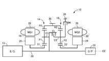
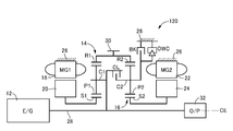
- FIG. 1 is a skeleton diagram illustrating the configuration of a hybrid vehicle drive device 10 (hereinafter simply referred to as drive device 10) to which the present invention is preferably applied.
- the drive device 10 of the present embodiment is a device for horizontal use that is preferably used in, for example, an FF (front engine front wheel drive) type vehicle and the like, and an engine 12, which is a main power source,
- the first electric motor MG1, the second electric motor MG2, the first planetary gear device 14 as a first differential mechanism, and the second planetary gear device 16 as a second differential mechanism are provided on a common central axis CE.
- the drive device 10 is configured substantially symmetrically with respect to the center axis CE, and in FIG. 1, the lower half of the center line is omitted. The same applies to each of the following embodiments.
- the engine 12 is, for example, an internal combustion engine such as a gasoline engine that generates driving force by combustion of fuel such as gasoline injected in a cylinder.
- the first electric motor MG1 and the second electric motor MG2 are preferably so-called motor generators each having a function as a motor (engine) for generating a driving force and a generator (generator) for generating a reaction force.
- the stators (stator) 18 and 22 are fixed to a housing (case) 26 which is a non-rotating member, and rotors (rotors) 20 and 24 are provided on the inner peripheral sides of the stators 18 and 22. ing.
- the first planetary gear unit 14 is a single pinion type planetary gear unit having a gear ratio ⁇ 1, and is a carrier as a second rotation element that supports the sun gear S1 and the pinion gear P1 as the first rotation element so as to be capable of rotating and revolving.
- a ring gear R1 as a third rotation element that meshes with the sun gear S1 via C1 and the pinion gear P1 is provided as a rotation element (element).
- the second planetary gear device 16 is a single pinion type planetary gear device having a gear ratio of ⁇ 2, and is a carrier as a second rotating element that supports the sun gear S2 and the pinion gear P2 as the first rotating element so as to be capable of rotating and revolving.
- a ring gear R2 as a third rotating element that meshes with the sun gear S2 via C2 and the pinion gear P2 is provided as a rotating element (element).
- the sun gear S1 of the first planetary gear unit 14 is connected to the rotor 20 of the first electric motor MG1.
- the carrier C1 of the first planetary gear device 14 is connected to an input shaft 28 that is rotated integrally with the crankshaft of the engine 12.
- the input shaft 28 is centered on the central axis CE.
- the direction of the central axis of the central axis CE is referred to as an axial direction (axial direction) unless otherwise distinguished.
- the ring gear R1 of the first planetary gear device 14 is connected to the output gear 30 that is an output rotating member, and is also connected to the ring gear R2 of the second planetary gear device 16.
- the sun gear S2 of the second planetary gear device 16 is connected to the rotor 24 of the second electric motor MG2.
- the driving force output from the output gear 30 is transmitted to a pair of left and right drive wheels (not shown) via a differential gear device and an axle (not shown).
- torque input to the drive wheels from the road surface of the vehicle is transmitted (input) from the output gear 30 to the drive device 10 via the differential gear device and the axle.
- a mechanical oil pump 32 such as a vane pump is connected to an end of the input shaft 28 opposite to the engine 12, and hydraulic pressure that is used as a source pressure of a hydraulic control circuit 60 and the like to be described later when the engine 12 is driven. Is output.
- an electric oil pump driven by electric energy may be provided.
- the carrier C1 of the first planetary gear unit 14 and the carrier C2 of the second planetary gear unit 16 are selectively engaged between the carriers C1 and C2 (disconnection between the carriers C1 and C2).
- a clutch CL is provided.
- a brake BK for selectively engaging (fixing) the carrier C2 with the housing 26 is provided between the carrier C2 of the second planetary gear device 16 and the housing 26 which is a non-rotating member.
- the clutch CL and the brake BK are preferably hydraulic engagement devices whose engagement states are controlled (engaged or released) according to the hydraulic pressure supplied from the hydraulic control circuit 60.
- a wet multi-plate friction engagement device or the like is preferably used, but a meshing engagement device, that is, a so-called dog clutch (meshing clutch) may be used.
- an engagement state may be controlled (engaged or released) according to an electrical command supplied from the electronic control device 40, such as an electromagnetic clutch or a magnetic powder clutch.
- the first planetary gear device 14 and the second planetary gear device 16 are arranged coaxially with the input shaft 28 (on the central axis CE), and the central axis CE. It arrange
- the second electric motor MG1 is disposed on the opposite side of the engine 12 with respect to the second planetary gear device 16. That is, the first electric motor MG1 and the second electric motor MG2 are arranged at positions facing each other with the first planetary gear device 14 and the second planetary gear device 16 interposed therebetween with respect to the axial direction of the central axis CE. That is, in the drive device 10, in the axial direction of the central axis CE, the first electric motor MG1, the first planetary gear device 14, the clutch CL, the second planetary gear device 16, the brake BK, and the second electric motor MG2 from the engine 12 side. In order, these components are arranged on the same axis.
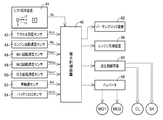
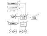
- FIG. 2 is a diagram for explaining a main part of a control system provided in the drive device 10 in order to control the drive of the drive device 10.
- the electronic control unit 40 shown in FIG. 2 includes a CPU, a ROM, a RAM, an input / output interface, and the like, and executes signal processing in accordance with a program stored in advance in the ROM while using a temporary storage function of the RAM.
- the microcomputer is a so-called microcomputer, and executes various controls related to driving of the drive device 10 including drive control of the engine 12 and hybrid drive control related to the first electric motor MG1 and the second electric motor MG2. That is, in this embodiment, the electronic control device 40 corresponds to a drive control device for a hybrid vehicle to which the drive device 10 is applied.
- the electronic control device 40 is configured as an individual control device for each control as necessary, such as for output control of the engine 12 and operation control of the first electric motor MG1 and the second electric motor MG2.
- the electronic control device 40 is configured to be supplied with various signals from sensors, switches, and the like provided in each part of the driving device 10. That is, a driver's output request is made by the operation position signal Sh output from the shift operating device 41 in response to a manual operation to a parking position, neutral position, forward travel position, reverse travel position, etc., and the accelerator opening sensor 42.
- a signal representing the accelerator opening a CC is an operation amount of an accelerator pedal (not shown) corresponding to the amount
- a signal indicative of engine rotational speed N E is the rotational speed of the engine 12 by the engine rotational speed sensor 44
- the MG1 rotational speed sensor 46 A signal representing the rotational speed N MG1 of the first electric motor MG1 , a signal representing the rotational speed N MG2 of the second electric motor MG2 by the MG2 rotational speed sensor 48, and a rotational speed N of the output gear 30 corresponding to the vehicle speed V by the output rotational speed sensor 50 signal representing the OUT, drives the wheel speed sensors 52 10
- Definitive signal representing each wheel respective speeds N W, and signal or the like indicative of a charged capacity (charged state) SOC of the battery (not shown) by the battery SOC sensor 54 are respectively supplied to the electronic control unit 40.
- the electronic control device 40 is configured to output an operation command to each part of the drive device 10. That is, as an engine output control command for controlling the output of the engine 12, a fuel injection amount signal for controlling a fuel supply amount to an intake pipe or the like by the fuel injection device, and an ignition timing (ignition timing) of the engine 12 by the ignition device are commanded. An ignition signal and an electronic throttle valve drive signal supplied to the throttle actuator for operating the throttle valve opening ⁇ TH of the electronic throttle valve are output to an engine control device 56 that controls the output of the engine 12.
- a command signal commanding the operation of the first motor MG1 and the second motor MG2 is output to the inverter 58, and electric energy corresponding to the command signal is transmitted from the battery to the first motor MG1 and the second motor MG2 via the inverter 58.
- the output (torque) of the first electric motor MG1 and the second electric motor MG2 is controlled by being supplied. Electric energy generated by the first electric motor MG1 and the second electric motor MG2 is supplied to the battery via the inverter 58 and stored in the battery.
- a command signal for controlling the engagement state of the clutch CL and the brake BK is supplied to an electromagnetic control valve such as a linear solenoid valve provided in the hydraulic control circuit 60, and the hydraulic pressure output from the electromagnetic control valve is controlled. The engagement state of the clutch CL and the brake BK is controlled. Further, a command signal for locking the rotation of the output gear 30 is supplied from the electronic control unit 40 to the parking lock device 62 in response to the operation position signal Sh indicating the parking position.
- the driving device 10 functions as an electric differential unit that controls the differential state between the input rotation speed and the output rotation speed by controlling the operation state via the first electric motor MG1 and the second electric motor MG2.
- the electric energy generated by the first electric motor MG1 is supplied to the battery and the second electric motor MG2 via the inverter 58.
- the main part of the power of the engine 12 is mechanically transmitted to the output gear 30, while a part of the power is consumed for power generation by the first electric motor MG 1 and is converted into electric energy there.
- the electric energy is supplied to the second electric motor MG2.
- the second electric motor MG2 is driven and the power output from the second electric motor MG2 is transmitted to the output gear 30.
- FIG. 3 is an engagement table showing the engagement states of the clutch CL and the brake BK in each of the five types of travel modes established in the drive device 10, with the engagement indicated by “ ⁇ ” and the release indicated by a blank. Yes.
- the operation of the engine 12 is stopped, and at least one of the first electric motor MG1 and the second electric motor MG2 is used as a driving source for traveling.
- EV traveling mode used as “HV-1”, “HV-2”, and “HV-3” are all driven by the first electric motor MG1 and the second electric motor MG2 as required while the engine 12 is driven as a driving source for traveling, for example. It is a hybrid travel mode in which power generation is performed. In this hybrid travel mode, a reaction force may be generated by at least one of the first electric motor MG1 and the second electric motor MG2, or may be idled in an unloaded state.
- the operation of the engine 12 is stopped, and in the EV traveling mode in which at least one of the first electric motor MG ⁇ b> 1 and the second electric motor MG ⁇ b> 2 is used as a driving source for traveling, Is engaged and the clutch CL is released to establish the EV-1 mode (travel mode 1), and the brake BK and the clutch CL are both engaged to establish the EV-2 mode (travel mode 2). Be made.
- the brake BK is engaged and the clutch CL is engaged.
- the HV-1 mode travel mode 3
- the brake BK is released and the clutch CL is engaged
- the HV-2 mode (travel mode 4) is set. Both the brake BK and the clutch CL are set.
- the HV-3 mode (travel mode 5) is established.
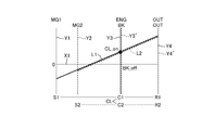
- the solid line Y1 is the sun gear S1 (first electric motor MG1) of the first planetary gear unit 14, the broken line Y2 is the sun gear S2 (second electric motor MG2) of the second planetary gear unit 16, and the solid line Y3.
- the carrier C1 (engine 12) of the first planetary gear unit 14 the broken line Y3 'is the carrier C2 of the second planetary gear unit 16
- the solid line Y4 is the ring gear R1 (output gear 30) of the first planetary gear unit 14, and the broken line Y4'.
- the relative rotational speeds of the three rotating elements in the first planetary gear unit 14 are indicated by a solid line L1
- the relative rotational speeds of the three rotating elements in the second planetary gear unit 16 are indicated by a broken line L2.
- the intervals between the vertical lines Y1 to Y4 are determined according to the gear ratios ⁇ 1 and ⁇ 2 of the first planetary gear device 14 and the second planetary gear device 16. That is, regarding the vertical lines Y1, Y3, Y4 corresponding to the three rotating elements in the first planetary gear device 14, the distance between the sun gear S1 and the carrier C1 corresponds to 1, and the distance between the carrier C1 and the ring gear R1. Corresponds to ⁇ 1.
- the space between the sun gear S2 and the carrier C2 corresponds to 1, and the space between the carrier C2 and the ring gear R2 Corresponds to ⁇ 2. That is, in the drive device 10, the gear ratio ⁇ 2 of the second planetary gear device 16 is preferably larger than the gear ratio ⁇ 1 of the first planetary gear device 14 ( ⁇ 2> ⁇ 1).
- each traveling mode in the driving apparatus 10 will be described with reference to FIGS.
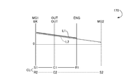
- the EV-1 mode shown in FIG. 3 is a first electric motor travel mode in which the operation of the engine 12 is stopped in the drive device 10 and the second electric motor MG2 is used as a travel drive source.
- FIG. 4 is a collinear diagram corresponding to the EV-1 mode. If described using this collinear diagram, the carrier C1 and the second planet of the first planetary gear unit 14 are released by releasing the clutch CL. The gear device 16 can rotate relative to the carrier C2. By engaging the brake BK, the carrier C2 of the second planetary gear device 16 is connected (fixed) to the housing 26, which is a non-rotating member, and its rotational speed is zero.
- the rotation direction of the sun gear S2 and the rotation direction of the ring gear R2 are opposite to each other, and negative torque (torque in the negative direction) is output by the second electric motor MG2.
- the ring gear R2 that is, the output gear 30 is rotated in the positive direction by the torque. That is, by outputting negative torque by the second electric motor MG2, the hybrid vehicle to which the drive device 10 is applied can travel forward. In this case, the first electric motor MG1 is idled.
- the EV-2 mode shown in FIG. 3 is a second electric motor traveling mode in which the operation of the engine 12 is stopped in the driving device 10 and at least one of the first electric motor MG1 and the second electric motor MG2 is used as a driving source for traveling. It is.
- FIG. 5 is a collinear diagram corresponding to the EV-2 mode. If the collinear diagram is used to explain, the carrier C1 and the second planetary gear device 14 of the first planetary gear unit 14 are engaged by engaging the clutch CL. The planetary gear device 16 cannot be rotated relative to the carrier C2.
- the carrier C2 of the second planetary gear device 16 and the carrier C1 of the first planetary gear device 14 engaged with the carrier C2 are connected to the housing 26 which is a non-rotating member. (Fixed) and the rotation speed is zero.
- the rotation direction of the sun gear S1 and the rotation direction of the ring gear R1 are opposite to each other, and in the second planetary gear device 16, the rotation direction of the sun gear S2 and the ring gear are reversed.
- the direction of rotation of R2 is the opposite direction.
- the hybrid vehicle to which the drive device 10 is applied can be moved forward or backward by at least one of the first electric motor MG1 and the second electric motor MG2.
- a mode in which power generation is performed by at least one of the first electric motor MG1 and the second electric motor MG2 can be established.
- torque limitation due to heat it is possible to run to ease restrictions such as torque limitation due to heat.
- the EV-2 mode it is possible to perform EV traveling under a wide range of traveling conditions, or to perform EV traveling continuously for a long time. Therefore, the EV-2 mode is suitably employed in a hybrid vehicle having a high ratio of EV traveling such as a plug-in hybrid vehicle.
- the HV-1 mode shown in FIG. 3 is used as a driving source for driving by driving the engine 12 in the driving device 10, and is driven or generated by the first electric motor MG1 and the second electric motor MG2 as necessary.
- the collinear diagram of FIG. 4 also corresponds to the HV-1 mode. If described with reference to this collinear diagram, the carrier C1 and the first planetary gear unit 14 of the first planetary gear unit 14 are released by releasing the clutch CL. The two planetary gear unit 16 can rotate relative to the carrier C2. By engaging the brake BK, the carrier C2 of the second planetary gear device 16 is connected (fixed) to the housing 26, which is a non-rotating member, and its rotational speed is zero.
- the engine 12 In the HV-1 mode, the engine 12 is driven, and the output gear 30 is rotated by the output torque. At this time, in the first planetary gear device 14, the output torque from the engine 12 can be transmitted to the output gear 30 by causing the first electric motor MG 1 to output the reaction torque.
- the rotation direction of the sun gear S2 and the rotation direction of the ring gear R2 are opposite because the brake BK is engaged. That is, when negative torque (negative direction torque) is output by the second electric motor MG2, the ring gears R1 and R2, that is, the output gear 30 are rotated in the positive direction by the torque.
- the HV-2 mode shown in FIG. 3 is used as a driving source for driving by driving the engine 12 in the driving device 10, and is driven or generated by the first electric motor MG1 and the second electric motor MG2 as necessary.
- This is the second hybrid (engine) travel mode.
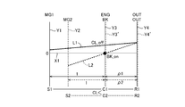
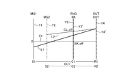
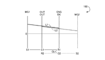
- FIG. 6 is a collinear diagram corresponding to the HV-2 mode. If described using this collinear diagram, the carrier C1 and the second planetary gear device 14 of the first planetary gear unit 14 are engaged by engaging the clutch CL. The planetary gear device 16 is not allowed to rotate relative to the carrier C2, and operates as one rotating element that rotates the carriers C1 and C2 integrally.
- the ring gears R1 and R2 Since the ring gears R1 and R2 are connected to each other, the ring gears R1 and R2 operate as one rotating element that is rotated integrally. That is, in the HV-2 mode, the rotating elements in the first planetary gear device 14 and the second planetary gear device 16 in the drive device 10 function as a differential mechanism including four rotating elements as a whole. That is, four gears in order from the left in FIG. 6 are the sun gear S1 (first electric motor MG1), the sun gear S2 (second electric motor MG2), the carriers C1 and C2 (engine 12) connected to each other, A composite split mode is obtained in which ring gears R1 and R2 (output gear 30) connected to each other are connected in this order.
- the arrangement order of the rotating elements in the first planetary gear device 14 and the second planetary gear device 16 is preferably the sun gear S1 indicated by the vertical line Y1.
- the sun gear S2 indicated by the vertical line Y2, the carriers C1 and C2 indicated by the vertical line Y3 (Y3 ′), and the ring gears R1 and R2 indicated by the vertical line Y4 (Y4 ′) are arranged in this order.
- the gear ratios ⁇ 1 and ⁇ 2 of the first planetary gear device 14 and the second planetary gear device 16 are respectively represented by a vertical line Y1 corresponding to the sun gear S1 and a vertical line Y2 corresponding to the sun gear S2, as shown in FIG.
- the interval between the vertical lines Y1 and Y3 is larger than the interval between the vertical lines Y2 and Y3 ′.
- the distance between the sun gears S1, S2 and the carriers C1, C2 corresponds to 1
- the distance between the carriers C1, C2 and the ring gears R1, R2 corresponds to ⁇ 1, ⁇ 2.
- the gear ratio ⁇ 2 of the second planetary gear device 16 is larger than the gear ratio ⁇ 1 of the first planetary gear device 14.
- the reaction force can be applied to the output of the engine 12 by either the first electric motor MG1 or the second electric motor MG2. That is, when the engine 12 is driven, the reaction force can be shared by one or both of the first electric motor MG1 and the second electric motor MG2, and the engine 12 can be operated at an efficient operating point, or the torque caused by heat. It is possible to run to ease restrictions such as restrictions.
- the efficiency can be improved by controlling the first motor MG1 and the second motor MG2 to receive the reaction force preferentially by the motor that can operate efficiently.
- the driving force is assisted by regeneration or output of an electric motor that is not torque limited, so that the engine 12 It is possible to ensure a reaction force necessary for driving.
- the HV-3 mode shown in FIG. 3 is a third hybrid in which the engine 12 is driven in the driving device 10 to be used as a driving source for traveling, and driving or power generation is performed by the first electric motor MG1 as necessary.
- (Engine) traveling mode In the HV-3 mode, the second electric motor MG2 can be separated from the drive system and driven by the engine 12 and the first electric motor MG1.
- FIG. 7 is a collinear diagram corresponding to the HV-3 mode. If the collinear diagram is used to explain, the carrier C1 of the first planetary gear unit 14 and the carrier C1 are released when the clutch CL is released. The second planetary gear device 16 can rotate relative to the carrier C2.
- the carrier C2 of the second planetary gear device 16 can be rotated relative to the housing 26, which is a non-rotating member.
- the second electric motor MG2 can be disconnected from the drive system (power transmission path) and stopped.
- the second electric motor MG2 is always rotated with the rotation of the output gear 30 (ring gear R2) when the vehicle is traveling.
- the rotation speed of the second electric motor MG2 reaches a limit value (upper limit value), or the rotation speed of the ring gear R2 is increased and transmitted to the sun gear S2. Therefore, from the viewpoint of improving efficiency, it is not always preferable to always rotate the second electric motor MG2 at a relatively high vehicle speed.
- the second electric motor MG2 in the HV-3 mode, by realizing a mode in which the second electric motor MG2 is disconnected from the drive system and driven by the engine 12 and the first electric motor MG1 at a relatively high vehicle speed, the second electric motor MG2 In addition to being able to reduce drag loss when driving is unnecessary, it is possible to eliminate restrictions on the maximum vehicle speed caused by the maximum rotation speed (upper limit value) allowed for the second electric motor MG2.
- the clutch CL and the brake BK are engaged or released in combination.
- Three modes, HV-1 mode, HV-2 mode, and HV-3 mode can be selectively established. Thereby, for example, by selectively establishing the mode with the highest transmission efficiency among these three modes according to the vehicle speed, the gear ratio, etc. of the vehicle, it is possible to improve the transmission efficiency and thus improve the fuel efficiency. it can.
- FIG. 8 is a functional block diagram illustrating a main part of the control function of the electronic control unit 40 of FIG.
- the engine stop request determination unit 70 determines whether or not there has been a stop request for the engine 12 from the driving state of the engine 12 (a state driven by the engine control device 56) while the vehicle is stopped or traveling. judge. For example, when the required driving force calculated from the accelerator opening and the vehicle speed falls below a predetermined determination value, when the SOC of the power storage device (not shown) exceeds the upper limit value and enters a charge restriction state, an ignition switch (not shown) Is switched from a state corresponding to an operation position (drive position) “ON” for driving the engine 12 to a state corresponding to an operation position (stop position) “OFF” for stopping the engine 12.
- Engine speed determining section 72 determines whether or not the engine rotational speed N E to be reduced by the stop request of the engine 12 falls below the switching threshold value, for example set in advance about 100 rpm.
- the mode determination unit 74 determines whether one of the five modes, EV-1 mode, EV-2 mode, HV-1 mode, HV-2 mode, and HV-3 mode, is established. The determination is made based on vehicle parameters such as A CC , SOC, operating temperature, the output state of the engine control device 56 and the inverter 58, the output state of the mode switching control unit 76, or an already set flag.
- the mode switching control unit 76 determines and switches the traveling mode to be established in the drive device 10. For example, based on whether the required driving force of the driver determined based on the vehicle speed V and the accelerator opening degree ACC is a preset electric traveling region or engine traveling region, or based on a request based on the SOC Then, it is determined whether it is electric traveling or hybrid traveling. When electric travel is selected, one of the EV-1 mode 1 and the EV-2 mode is selected based on a request based on the SOC, a driver's selection, and the like.
- the HV-1 mode, the HV-2 mode, and the HV are set so that the driving force and the fuel consumption are compatible based on the efficiency and transmission efficiency of the engine 12, the magnitude of the required driving force, and the like.
- Select one of the -3 modes For example, the establishment of the HV-1 mode is selected for the low gear at low vehicle speed (high reduction ratio region), and the establishment of the HV-2 mode is selected for the middle gear (medium reduction ratio region) for medium vehicle speed. In the (reduction speed ratio range), establishment of the HV-3 mode is selected.
- the mode switching control unit 76 engages at least one of the clutch CL and the brake BK via the hydraulic control circuit 60 so that the selected mode is established.
- the engine stop control unit 78 determines that an engine stop request has been issued by the engine stop request determination unit 70 while the vehicle is stopped or traveling, the fuel injection that has been performed via the engine control device 56 is performed. Control of fuel supply to the intake pipe or the like by the device and ignition or the like by the ignition device is stopped, and the operation (operation) of the engine 12 is stopped.
- the power transmission system is a device related to power transmission from a driving source to driving wheels, that is, a so-called drive line.
- an engine 12 as a driving source.
- the first planetary gear device 14, the second planetary gear device 16, the input shaft 28, and the output gear 30 provided in the power transmission path from the first electric motor MG1, the second electric motor MG2, and the like to the driving wheel (not shown).
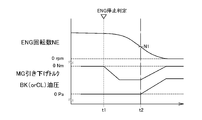
- the engine stop control unit 78 after the operation of the engine 12 is stopped, so that the engine rotational speed decreases quickly than the rate at which is lowered with consequences, the engine rotational speed N E is lowered the direction of the torque is outputted from the first electric motor MG1, the engine speed N E so as to quickly pass through the resonance range.
- Aggressive lowering of the first electric motor MG1 by the engine rotational speed N E may also be operated in the engine 12 is started immediately after being stopped, but experimentally expected that resonance is initiated For example, it may be started when the value falls below a predetermined start determination value of about 400 to 500 rpm.
- Aggressive lowering stroke of the engine speed N E according to the first electric motor MG1 corresponds to the electric motor cuts step or motor cuts phase.
- the engine stop control section 78 following a positive reduction of the engine speed N E according to the first electric motor MG1, the engine rotational speed determination unit 72, the engine rotational speed is decreased by the stop request of the engine 12 N E is, for example, 200 when the engine 12 is determined to have fallen below the switching threshold value N1 which is set in advance empirically so as not to reverse the order of ⁇ 300 rpm, aggressive engine speed N E according to the first electric motor MG1
- the engine speed NE is stopped by engaging both the clutch CL and the brake BK. This reduction of the engine speed N E by engagement of both clutches CL and the brake BK correspond to friction reduction step or friction reduction phase.
- the engine stop control unit 78 starts the engagement of the clutch CL in addition to the fact that the brake BK is already engaged when the mode determination unit 74 determines that the mode is the HV-1 mode.
- the engine speed NE is quickly stopped, while if the mode determination unit 74 determines that the HV-2 mode is selected, the clutch CL has already been engaged.
- the engine speed NE is quickly stopped.
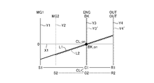
- the clutch CL and the brake BK are both engaged, and the rotation of the input shaft 28 and the engine 12 connected thereto is stopped by frictional engagement.
- the reverse rotation of the engine speed N E at the time of stopping the engine 12 is prevented.
- FIG. 9 shows that when the clutch CL and the brake BK are engaged together, the rotation of the input shaft 28 and the engine 12 connected thereto is stopped by frictional engagement, that is, the engine rotational speed NE is stopped.
- the collinear diagram is shown.
- the alignment chart of FIG. 9 shows a case where the vehicle is stopped, the vehicle is not necessarily stopped, and the engine stop control may be executed during traveling.
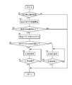
- FIG. 10 is a flowchart for explaining a main part of the control operation of the electronic control unit 40 of FIG. 2, and is repeatedly executed at a predetermined control cycle.
- step (hereinafter, step is omitted) S1 corresponding to the engine stop request determination unit 70 it is determined whether or not an engine stop request is issued during vehicle travel. If the determination at S1 is negative, this routine is terminated. However, if the determination in S1 is affirmative, with operation of the engine 12 is stopped at S5 corresponding to the engine stop control unit 78, aggressive reduction of the engine speed N E by the first electric motor MG1 is started The This state is shown at time t1 in FIG.
- the hybrid vehicle drive control apparatus 10 of the present embodiment when a stop request of the engine 12, after reducing the engine speed N E by the first electric motor MG1 advance, clutch Since at least one of the CL and the brake BK is engaged and the engine rotational speed NE is stopped by the engagement of both the clutch CL and the brake BK, the noise and the noise are suppressed regardless of the presence of the compression reaction force of the engine 12.
- the engine 12 can be quickly stopped without generating vibration.
- the engine speed NE is reduced by the first electric motor in advance compared to the case where the engine speed NE is stopped by engaging the clutch CL and the brake BK from the beginning, at least the clutch CL and the brake BK One endurance is improved.
- the drive control device 10 for a hybrid vehicle of the embodiment based on the engine rotational speed N E is below the set switching threshold value N1 in advance, at least one of the engagement start of the clutch CL and the brake BK from being, until below the engine rotational speed N E is preset switching threshold value N1, since the engine rotational speed N E by pre-first motor MG1 is pulled, at least one of durability of the clutches CL and the brake BK sexuality is enhanced.
- the first hybrid travel mode (HV-1 mode) in which the brake BK is engaged and the clutch CL is disengaged is provided.
- the engine stop request since to initiate engagement of the clutch CL to stop the engine rotational speed N E, stops the engine rotational speed N E by engagement friction clutch CL Therefore, regardless of the presence of the compression reaction force of the engine 12, the engine 12 can be quickly stopped without generating noise or vibration.
- the travel mode includes the second hybrid travel mode (HV-2 mode) that travels with the brake BK released and the clutch CL engaged.
- HV-2 mode the second hybrid travel mode
- the engine stop request since to initiate engagement of the brake BK to stop the engine rotational speed N E, stops the engine rotational speed N E by engagement of friction brake BK Therefore, regardless of the presence of the compression reaction force of the engine 12, the engine 12 can be quickly stopped without generating noise or vibration.
- the drive control device for a hybrid vehicle according to the present invention like the drive device 100 shown in FIG. 12 and the drive device 110 shown in FIG. 13, is the first electric motor MG1, the first planetary gear device 14, and the second The present invention is also preferably applied to a configuration in which the arrangement (arrangement) of the electric motor MG2, the second planetary gear device 16, the clutch CL, and the brake BK is changed.
- the driving device 120 shown in FIG. 12 is the first electric motor MG1, the first planetary gear device 14, and the second
- the present invention is also preferably applied to a configuration in which the arrangement (arrangement) of the electric motor MG2, the second planetary gear device 16, the clutch CL, and the brake BK is changed.
- the carrier C2 is allowed to rotate in one direction with respect to the housing 26 between the carrier C2 of the second planetary gear device 16 and the housing 26 that is a non-rotating member.
- the present invention is also suitably applied to a configuration in which a one-way clutch (one-way clutch) OWC that prevents rotation in the reverse direction is provided in parallel with the brake BK.
- a one-way clutch one-way clutch
- OWC one-way clutch
- the present invention is also preferably applied to a configuration including a pinion type second planetary gear device 16 '.
- the second planetary gear device 16 ' includes a sun gear S2' as a first rotation element, a carrier C2 'as a second rotation element that supports a plurality of pinion gears P2' meshed with each other so as to rotate and revolve, and a pinion gear.
- a ring gear R2 ′ as a third rotating element meshing with the sun gear S2 ′ via P2 ′ is provided as a rotating element (element).
- the hybrid vehicle drive device 100, 110, 120, 130, 140, 150 of the present embodiment includes the sun gear S1 as the first rotating element coupled to the first electric motor MG1 and the first gear coupled to the engine 12.
- a first planetary gear unit 14 as a first differential mechanism including a carrier C1 as a two-rotation element and a ring gear R1 as a third rotation element coupled to an output gear 30 as an output rotation member; and a second electric motor
- a sun gear S2 (S2 ') as a first rotating element coupled to MG2, a carrier C2 (C2') as a second rotating element, and a ring gear R2 (R2 ') as a third rotating element, these carriers C2 (C2 ′) and any one of the ring gear R2 (R2 ′) is a second differential mechanism that is connected to the ring gear R1 of the first planetary gear unit 14.
- the carrier C1 in the first planetary gear device 14 and the rotating element not connected to the ring gear R1 of the carrier C2 (C2') and the ring gear R2 (R2 ') And a rotating element which is not connected to the ring gear R1 out of the carrier C2 (C2 ′) and the ring gear R2 (R2 ′) to the housing 26 which is a non-rotating member. And a brake BK that is selectively engaged with the brake BK. For this reason, the same effects as those of the first embodiment can be obtained by providing the electronic control device 40 of the first embodiment.
- FIG. 18 to 20 are collinear diagrams illustrating the configuration and operation of other hybrid vehicle drive devices 160, 170, and 180 to which the present invention is preferably applied as an alternative to the drive device 10.
- FIG. 18 to 20 the relative rotational speeds of the sun gear S1, the carrier C1, and the ring gear R1 in the first planetary gear device 14 are indicated by the solid line L1 as in the collinear charts of FIGS.
- the relative rotational speeds of the sun gear S2, the carrier C2, and the ring gear R2 in the second planetary gear device 16 are indicated by broken lines L2.
- the sun gear S1, the carrier C1, and the ring gear R1 of the first planetary gear device 14 are connected to the first electric motor MG1, the engine 12, and the second electric motor MG2, respectively. Yes.
- the sun gear S2, the carrier C2, and the ring gear R2 of the second planetary gear device 16 are connected to the housing 26 via the second electric motor MG2, the output gear 30, and the brake BK, respectively.
- the sun gear S1 and the ring gear R2 are selectively connected via the clutch CL.
- the ring gear R1 and the sun gear S2 are connected to each other.
- the sun gear S1, the carrier C1, and the ring gear R1 of the first planetary gear device 14 are connected to the first electric motor MG1, the output gear 30, and the engine 12, respectively.
- the sun gear S2, the carrier C2, and the ring gear R2 of the second planetary gear device 16 are connected to the housing 26 via the second electric motor MG2, the output gear 30, and the brake BK, respectively.
- the sun gear S1 and the ring gear R2 are selectively connected via the clutch CL.
- the clutches C1 and C2 are connected to each other.
- the sun gear S1, the carrier C1, and the ring gear R1 of the first planetary gear device 14 are connected to the first electric motor MG1, the output gear 30, and the engine 12, respectively. .
- the sun gear S2, the carrier C2, and the ring gear R2 of the second planetary gear device 16 are connected to the housing 26 and the output gear 30 through the second electric motor MG2 and the brake BK, respectively.
- the ring gear R1 and the carrier C2 are selectively connected via a clutch CL.
- the carrier C1 and the ring gear R2 are connected to each other.
- the first difference having four rotating elements (expressed as four rotating elements) on the collinear chart is the same as the embodiment shown in FIGS.
- a rotating element is selectively connected via a clutch CL, and the rotating element of the second planetary gear devices 16 and 16 'to be engaged by the clutch CL is braked against the housing 26 which is a non-rotating member.
- a clutch CL a clutch for a hybrid vehicle which is selectively connected Te
- Te a drive control apparatus for a hybrid vehicle which is selectively connected Te
- the hybrid vehicle drive control apparatus of the present invention described above with reference to FIG. 9 and the like is also suitably applied to the configurations shown in FIGS.
- the clutch CL there are four rotating elements as a whole in a state in which the clutch CL is engaged (represented as four rotating elements on the collinear chart shown in FIGS. 4 to 7 and the like).
- the first planetary gear unit 14 that is the first differential mechanism and the second planetary gear units 16 and 16 'that are the second differential mechanism, and the engine 12 and the first electric motor MG1 that are respectively connected to these four rotating elements.
- the second electric motor MG2 and the output gear 30 as an output rotating member, and one of the four rotating elements is a rotating element of the first differential mechanism and a rotating element of the second differential mechanism.
- Hybrid vehicle drive device 12 Engine 14: First planetary gear device (first differential mechanism) 16, 16 ': Second planetary gear device (second differential mechanism) 18, 22: Stator 20, 24: Rotor 26: Housing (non-rotating member) 28: Input shaft 30: Output gear (output rotating member) 40: Electronic control device (drive control device) 70: Engine stop request determination unit 72: Engine speed determination unit 74: Mode determination unit 76: Mode switching control unit 78: Engine stop control unit BK: Brake CL: Clutch C1, C2, C2 ': Carrier (second rotation element) ) MG1: first electric motor MG2: second electric motor R1, R2, R2 ': ring gear (third rotating element) S1, S2, S2 ': Sun gear (first rotating element)
Abstract
Description
12:エンジン
14:第1遊星歯車装置(第1差動機構)
16、16′:第2遊星歯車装置(第2差動機構)
18、22:ステータ
20、24:ロータ
26:ハウジング(非回転部材)
28:入力軸
30:出力歯車(出力回転部材)
40:電子制御装置(駆動制御装置)
70:エンジン停止要求判定部
72:エンジン回転数判定部
74:モード判定部
76:モード切換制御部
78:エンジン停止制御部
BK:ブレーキ
CL:クラッチ
C1、C2、C2′:キャリア(第2回転要素)
MG1:第1電動機
MG2:第2電動機
R1、R2、R2′:リングギヤ(第3回転要素)
S1、S2、S2′:サンギヤ(第1回転要素)
Claims (5)
- 全体として4つの回転要素を有する第1差動機構及び第2差動機構と、該4つの回転要素にそれぞれ連結されたエンジン、第1電動機、第2電動機、及び出力回転部材とを、備え、
前記4つの回転要素のうちの1つは、前記第1差動機構の回転要素と前記第2差動機構の回転要素とがクラッチを介して選択的に連結され、
該クラッチによる係合対象となる前記第1差動機構又は前記第2差動機構の回転要素が、非回転部材に対してブレーキを介して選択的に連結される
ハイブリッド車両の駆動制御装置であって、
前記エンジンの停止要求があった場合には、前記第1電動機によりエンジン回転速度を低下させた後、前記クラッチおよびブレーキの少なくとも一方を係合開始させて該エンジン回転速度を停止させることを特徴とするハイブリッド車両の駆動制御装置。 - 前記エンジン回転速度が予め設定された切換判定値を下回ったことに基づいて、前記クラッチおよびブレーキの少なくとも一方の係合が開始されることを特徴とする請求項1のハイブリッド車両の駆動制御装置。
- 走行モードとして、前記ブレーキを係合させ且つ前記クラッチを解放させて走行する第1ハイブリッド走行モードを有し、
前記エンジン停止要求時に前記第1ハイブリッド走行モードである場合は、前記エンジン回転速度を停止させるために前記クラッチの係合を開始させることを特徴とする請求項1または2のハイブリッド車両の駆動制御装置。 - 走行モードとして、前記ブレーキを解放させ且つ前記クラッチを係合させて走行する第2ハイブリッド走行モードを有し、
前記エンジン停止要求時に前記第2ハイブリッド走行モードである場合は、前記エンジン回転速度を停止させるために前記ブレーキの係合を開始させることを特徴とする請求項1または2のハイブリッド車両の駆動制御装置。 - 前記第1差動機構は、前記第1電動機に連結された第1回転要素、前記エンジンに連結された第2回転要素、及び前記出力回転部材に連結された第3回転要素を備えたものであり、
前記第2差動機構は、前記第2電動機に連結された第1回転要素、第2回転要素、及び第3回転要素を備え、それら第2回転要素及び第3回転要素の何れか一方が前記第1差動機構における第3回転要素に連結されたものであり、
前記クラッチは、前記第1差動機構における第2回転要素と、前記第2差動機構における第2回転要素及び第3回転要素のうち前記第1差動機構における第3回転要素に連結されていない方の回転要素とを選択的に係合させるものであり、
前記ブレーキは、前記第2差動機構における第2回転要素及び第3回転要素のうち前記第1差動機構における第3回転要素に連結されていない方の回転要素を、前記非回転部材に対して選択的に係合させるものである
請求項1から4の何れか1項に記載のハイブリッド車両の駆動制御装置。
Priority Applications (4)
| Application Number | Priority Date | Filing Date | Title |
|---|---|---|---|
| EP12872475.4A EP2832609A1 (en) | 2012-03-26 | 2012-03-26 | Drive control device for hybrid vehicle |
| CN201280071657.6A CN104203696A (zh) | 2012-03-26 | 2012-03-26 | 混合动力车辆的驱动控制装置 |
| PCT/JP2012/057808 WO2013145089A1 (ja) | 2012-03-26 | 2012-03-26 | ハイブリッド車両の駆動制御装置 |
| US14/387,658 US20150051773A1 (en) | 2012-03-26 | 2012-03-26 | Drive control device for hybrid vehicle |
Applications Claiming Priority (1)
| Application Number | Priority Date | Filing Date | Title |
|---|---|---|---|
| PCT/JP2012/057808 WO2013145089A1 (ja) | 2012-03-26 | 2012-03-26 | ハイブリッド車両の駆動制御装置 |
Publications (1)
| Publication Number | Publication Date |
|---|---|
| WO2013145089A1 true WO2013145089A1 (ja) | 2013-10-03 |
Family
ID=49258459
Family Applications (1)
| Application Number | Title | Priority Date | Filing Date |
|---|---|---|---|
| PCT/JP2012/057808 WO2013145089A1 (ja) | 2012-03-26 | 2012-03-26 | ハイブリッド車両の駆動制御装置 |
Country Status (4)
| Country | Link |
|---|---|
| US (1) | US20150051773A1 (ja) |
| EP (1) | EP2832609A1 (ja) |
| CN (1) | CN104203696A (ja) |
| WO (1) | WO2013145089A1 (ja) |
Cited By (3)
| Publication number | Priority date | Publication date | Assignee | Title |
|---|---|---|---|---|
| CN104859634A (zh) * | 2015-05-07 | 2015-08-26 | 郑州宇通客车股份有限公司 | 一种混合动力汽车发动机快速停机方法和混合动力系统 |
| EP3086971A4 (en) * | 2013-12-23 | 2017-10-18 | Scania CV AB | A traction system for a vehicle |
| JP2017203401A (ja) * | 2016-05-10 | 2017-11-16 | 株式会社デンソー | エンジン停止始動制御装置 |
Families Citing this family (5)
| Publication number | Priority date | Publication date | Assignee | Title |
|---|---|---|---|---|
| WO2013145093A1 (ja) * | 2012-03-26 | 2013-10-03 | トヨタ自動車株式会社 | ハイブリッド車両の駆動制御装置 |
| SE1350768A1 (sv) * | 2012-06-27 | 2013-12-28 | Scania Cv Ab | Förfarande för framförande av ett fordon |
| KR101794898B1 (ko) | 2013-12-23 | 2017-12-01 | 스카니아 씨브이 악티에볼라그 | 차량용 추진 시스템 |
| US10246082B2 (en) | 2013-12-23 | 2019-04-02 | Scania Cv Ab | Propulsion system for a vehicle |
| US9988041B2 (en) * | 2016-06-13 | 2018-06-05 | Ford Global Technologies, Llc | System and method for controlling a vehicle powertrain |
Citations (4)
| Publication number | Priority date | Publication date | Assignee | Title |
|---|---|---|---|---|
| JP2005199942A (ja) * | 2004-01-19 | 2005-07-28 | Toyota Motor Corp | 動力出力装置およびこれを搭載する自動車並びに動力伝達装置 |
| JP2006077859A (ja) * | 2004-09-08 | 2006-03-23 | Nissan Motor Co Ltd | ハイブリッド車の駆動装置 |
| JP2008265600A (ja) | 2007-04-23 | 2008-11-06 | Toyota Motor Corp | 車両およびその制御方法 |
| JP2009067270A (ja) * | 2007-09-14 | 2009-04-02 | Toyota Motor Corp | 車両用動力伝達装置の制御装置 |
Family Cites Families (4)
| Publication number | Priority date | Publication date | Assignee | Title |
|---|---|---|---|---|
| JP4259494B2 (ja) * | 2005-03-04 | 2009-04-30 | トヨタ自動車株式会社 | 車両用駆動装置の制御装置 |
| JP4941096B2 (ja) * | 2007-05-23 | 2012-05-30 | トヨタ自動車株式会社 | 動力出力装置、それを備えた車両、および動力出力装置の制御方法 |
| US8335623B2 (en) * | 2007-10-25 | 2012-12-18 | GM Global Technology Operations LLC | Method and apparatus for remediation of and recovery from a clutch slip event in a hybrid powertrain system |
| US20140194239A1 (en) * | 2011-08-10 | 2014-07-10 | Toyota Jidosha Kabushiki Kaisha | Hybrid vehicle driving device |
-
2012
- 2012-03-26 US US14/387,658 patent/US20150051773A1/en not_active Abandoned
- 2012-03-26 WO PCT/JP2012/057808 patent/WO2013145089A1/ja active Application Filing
- 2012-03-26 EP EP12872475.4A patent/EP2832609A1/en not_active Withdrawn
- 2012-03-26 CN CN201280071657.6A patent/CN104203696A/zh active Pending
Patent Citations (4)
| Publication number | Priority date | Publication date | Assignee | Title |
|---|---|---|---|---|
| JP2005199942A (ja) * | 2004-01-19 | 2005-07-28 | Toyota Motor Corp | 動力出力装置およびこれを搭載する自動車並びに動力伝達装置 |
| JP2006077859A (ja) * | 2004-09-08 | 2006-03-23 | Nissan Motor Co Ltd | ハイブリッド車の駆動装置 |
| JP2008265600A (ja) | 2007-04-23 | 2008-11-06 | Toyota Motor Corp | 車両およびその制御方法 |
| JP2009067270A (ja) * | 2007-09-14 | 2009-04-02 | Toyota Motor Corp | 車両用動力伝達装置の制御装置 |
Cited By (7)
| Publication number | Priority date | Publication date | Assignee | Title |
|---|---|---|---|---|
| EP3086971A4 (en) * | 2013-12-23 | 2017-10-18 | Scania CV AB | A traction system for a vehicle |
| EP3086964A4 (en) * | 2013-12-23 | 2017-10-18 | Scania CV AB | A method of turning off a combustion engine of a driving vehicle |
| US10099676B2 (en) | 2013-12-23 | 2018-10-16 | Scania Cv Ab | Traction system for a vehicle |
| US10618509B2 (en) | 2013-12-23 | 2020-04-14 | Scania Cv Ab | Method of starting a vehicle with power balance |
| CN104859634A (zh) * | 2015-05-07 | 2015-08-26 | 郑州宇通客车股份有限公司 | 一种混合动力汽车发动机快速停机方法和混合动力系统 |
| JP2017203401A (ja) * | 2016-05-10 | 2017-11-16 | 株式会社デンソー | エンジン停止始動制御装置 |
| WO2017195629A1 (ja) * | 2016-05-10 | 2017-11-16 | 株式会社デンソー | エンジン停止始動制御装置 |
Also Published As
| Publication number | Publication date |
|---|---|
| US20150051773A1 (en) | 2015-02-19 |
| EP2832609A8 (en) | 2015-05-20 |
| CN104203696A (zh) | 2014-12-10 |
| EP2832609A1 (en) | 2015-02-04 |
Similar Documents
| Publication | Publication Date | Title |
|---|---|---|
| JP6114255B2 (ja) | ハイブリッド車両の駆動制御装置 | |
| JP5967105B2 (ja) | ハイブリッド車両の駆動制御装置 | |
| JP5884897B2 (ja) | ハイブリッド車両の駆動制御装置 | |
| JP5874814B2 (ja) | ハイブリッド車両の駆動制御装置 | |
| WO2013145089A1 (ja) | ハイブリッド車両の駆動制御装置 | |
| JP5874812B2 (ja) | ハイブリッド車両の駆動制御装置 | |
| WO2013145100A1 (ja) | ハイブリッド車両の駆動制御装置 | |
| WO2013140546A1 (ja) | ハイブリッド車両の駆動制御装置 | |
| JP6024740B2 (ja) | ハイブリッド車両の駆動制御装置 | |
| WO2013145099A1 (ja) | ハイブリッド車両の駆動制御装置 | |
| JP5884893B2 (ja) | ハイブリッド車両の駆動制御装置 | |
| WO2013145102A1 (ja) | ハイブリッド車両の駆動制御装置 | |
| WO2013094005A1 (ja) | ハイブリッド車両の駆動制御装置 | |
| JP5874813B2 (ja) | ハイブリッド車両の駆動制御装置 | |
| JPWO2013145097A1 (ja) | ハイブリッド車両の駆動制御装置 | |
| WO2013140545A1 (ja) | ハイブリッド車両の駆動制御装置 | |
| WO2013140538A1 (ja) | ハイブリッド車両の駆動制御装置 | |
| WO2013140539A1 (ja) | ハイブリッド車両の駆動制御装置 | |
| JP2013203386A (ja) | ハイブリッド車両の駆動制御装置 | |
| JP2013203388A (ja) | ハイブリッド車両の駆動制御装置 | |
| WO2013145098A1 (ja) | ハイブリッド車両の駆動制御装置 | |
| JP2013203385A (ja) | ハイブリッド車両の駆動制御装置 | |
| JP2013203383A (ja) | ハイブリッド車両の駆動制御装置 | |
| JPWO2013145089A1 (ja) | ハイブリッド車両の駆動制御装置 | |
| JPWO2013140546A1 (ja) | ハイブリッド車両の駆動制御装置 |
Legal Events
| Date | Code | Title | Description |
|---|---|---|---|
| 121 | Ep: the epo has been informed by wipo that ep was designated in this application |
Ref document number: 12872475 Country of ref document: EP Kind code of ref document: A1 |
|
| WWE | Wipo information: entry into national phase |
Ref document number: 14387658 Country of ref document: US |
|
| ENP | Entry into the national phase |
Ref document number: 2014507060 Country of ref document: JP Kind code of ref document: A |
|
| NENP | Non-entry into the national phase |
Ref country code: DE |
|
| WWE | Wipo information: entry into national phase |
Ref document number: 2012872475 Country of ref document: EP |