WO2013141019A1 - 転写フィルム、転写方法及びインクジェット記録装置 - Google Patents
転写フィルム、転写方法及びインクジェット記録装置 Download PDFInfo
- Publication number
- WO2013141019A1 WO2013141019A1 PCT/JP2013/056033 JP2013056033W WO2013141019A1 WO 2013141019 A1 WO2013141019 A1 WO 2013141019A1 JP 2013056033 W JP2013056033 W JP 2013056033W WO 2013141019 A1 WO2013141019 A1 WO 2013141019A1
- Authority
- WO
- WIPO (PCT)
- Prior art keywords
- layer
- transfer
- ink
- sublimation ink
- mask layer
- Prior art date
- Legal status (The legal status is an assumption and is not a legal conclusion. Google has not performed a legal analysis and makes no representation as to the accuracy of the status listed.)
- Ceased
Links
Images

Classifications
-
- B—PERFORMING OPERATIONS; TRANSPORTING
- B41—PRINTING; LINING MACHINES; TYPEWRITERS; STAMPS
- B41J—TYPEWRITERS; SELECTIVE PRINTING MECHANISMS, i.e. MECHANISMS PRINTING OTHERWISE THAN FROM A FORME; CORRECTION OF TYPOGRAPHICAL ERRORS
- B41J2/00—Typewriters or selective printing mechanisms characterised by the printing or marking process for which they are designed
- B41J2/005—Typewriters or selective printing mechanisms characterised by the printing or marking process for which they are designed characterised by bringing liquid or particles selectively into contact with a printing material
- B41J2/0057—Typewriters or selective printing mechanisms characterised by the printing or marking process for which they are designed characterised by bringing liquid or particles selectively into contact with a printing material where an intermediate transfer member receives the ink before transferring it on the printing material
-
- B—PERFORMING OPERATIONS; TRANSPORTING
- B44—DECORATIVE ARTS
- B44C—PRODUCING DECORATIVE EFFECTS; MOSAICS; TARSIA WORK; PAPERHANGING
- B44C1/00—Processes, not specifically provided for elsewhere, for producing decorative surface effects
- B44C1/16—Processes, not specifically provided for elsewhere, for producing decorative surface effects for applying transfer pictures or the like
- B44C1/165—Processes, not specifically provided for elsewhere, for producing decorative surface effects for applying transfer pictures or the like for decalcomanias; sheet material therefor
- B44C1/17—Dry transfer
-
- B—PERFORMING OPERATIONS; TRANSPORTING
- B41—PRINTING; LINING MACHINES; TYPEWRITERS; STAMPS
- B41J—TYPEWRITERS; SELECTIVE PRINTING MECHANISMS, i.e. MECHANISMS PRINTING OTHERWISE THAN FROM A FORME; CORRECTION OF TYPOGRAPHICAL ERRORS
- B41J2/00—Typewriters or selective printing mechanisms characterised by the printing or marking process for which they are designed
- B41J2/005—Typewriters or selective printing mechanisms characterised by the printing or marking process for which they are designed characterised by bringing liquid or particles selectively into contact with a printing material
- B41J2/01—Ink jet
-
- B—PERFORMING OPERATIONS; TRANSPORTING
- B41—PRINTING; LINING MACHINES; TYPEWRITERS; STAMPS
- B41J—TYPEWRITERS; SELECTIVE PRINTING MECHANISMS, i.e. MECHANISMS PRINTING OTHERWISE THAN FROM A FORME; CORRECTION OF TYPOGRAPHICAL ERRORS
- B41J31/00—Ink ribbons; Renovating or testing ink ribbons
-
- B—PERFORMING OPERATIONS; TRANSPORTING
- B41—PRINTING; LINING MACHINES; TYPEWRITERS; STAMPS
- B41M—PRINTING, DUPLICATING, MARKING, OR COPYING PROCESSES; COLOUR PRINTING
- B41M5/00—Duplicating or marking methods; Sheet materials for use therein
- B41M5/025—Duplicating or marking methods; Sheet materials for use therein by transferring ink from the master sheet
- B41M5/035—Duplicating or marking methods; Sheet materials for use therein by transferring ink from the master sheet by sublimation or volatilisation of pre-printed design, e.g. sublistatic
-
- D—TEXTILES; PAPER
- D06—TREATMENT OF TEXTILES OR THE LIKE; LAUNDERING; FLEXIBLE MATERIALS NOT OTHERWISE PROVIDED FOR
- D06P—DYEING OR PRINTING TEXTILES; DYEING LEATHER, FURS OR SOLID MACROMOLECULAR SUBSTANCES IN ANY FORM
- D06P5/00—Other features in dyeing or printing textiles, or dyeing leather, furs, or solid macromolecular substances in any form
- D06P5/003—Transfer printing
- D06P5/004—Transfer printing using subliming dyes
-
- B—PERFORMING OPERATIONS; TRANSPORTING
- B41—PRINTING; LINING MACHINES; TYPEWRITERS; STAMPS
- B41J—TYPEWRITERS; SELECTIVE PRINTING MECHANISMS, i.e. MECHANISMS PRINTING OTHERWISE THAN FROM A FORME; CORRECTION OF TYPOGRAPHICAL ERRORS
- B41J2/00—Typewriters or selective printing mechanisms characterised by the printing or marking process for which they are designed
- B41J2/005—Typewriters or selective printing mechanisms characterised by the printing or marking process for which they are designed characterised by bringing liquid or particles selectively into contact with a printing material
- B41J2/01—Ink jet
- B41J2002/012—Ink jet with intermediate transfer member
-
- B—PERFORMING OPERATIONS; TRANSPORTING
- B41—PRINTING; LINING MACHINES; TYPEWRITERS; STAMPS
- B41M—PRINTING, DUPLICATING, MARKING, OR COPYING PROCESSES; COLOUR PRINTING
- B41M2205/00—Printing methods or features related to printing methods; Location or type of the layers
- B41M2205/14—Production or use of a mask
Definitions
- the present invention relates to a transfer film, a transfer method, and an ink jet recording apparatus for transferring an image from a substrate to a transfer medium.
- Patent Document 1 describes a method of forming an image by heating a printing medium and diffusing and coloring sublimation dye ink on the surface of the medium body.
- the sublimation dye impregnated in the ink image-receiving sheet diffuses in the plane direction when the ink fixing layer is thick, and the image outline is blurred. It is also conceivable to prevent diffusion of the sublimable dye in the planar direction by making the ink fixing layer thin. However, if the ink fixing layer is thinned, the ink fixing layer cannot be formed so as to straddle between the fibers when the medium on which the image is to be formed is a rough material such as a cloth. Therefore, there is a problem that the image quality is deteriorated.
- the present invention has been made in view of such problems, and an object of the present invention is to form an image on which a contour is not blurred on a transfer medium even when a sublimation ink is used and an ink fixing layer is thickened.
- the transfer film according to the present invention includes a base material, a transfer binder layer provided on the base material, and a layer provided on the transfer binder layer and formed with an image for transferring to a transfer medium using sublimation ink.
- the transfer binder layer penetrates when the sublimation ink sublimates. It is made up of materials.
- an ink fixing layer is formed. Even when the sublimation ink diffuses in the plane direction of the ink fixing layer when this is transferred to the transfer medium, the transfer of the sublimation ink that has spread to the region is prevented by the mask layer. That is, since only the sublimation ink of the ink fixing layer only in a desired region is transferred onto the transfer medium by the mask layer, it is possible to prevent the outline of the image from blurring. Therefore, even when sublimation ink is used and the ink fixing layer is thickened, an image with no blurred outline can be formed on the transfer medium.
- the mask layer is provided on the transfer binder layer and in an area where the sublimation ink layer is not provided.
- the transfer film can be easily produced. Further, the amount of sublimation ink can be reduced as compared with the case where the sublimation ink layer is solidly formed on the transfer binder layer. Further, compared to the case where the mask layer is formed on the sublimation ink layer, the concentration of the ink in the region where the image of the sublimation ink layer is formed can be increased. This is because if the mask layer is formed adjacent to the sublimation ink layer, the mask layer can prevent the ink from diffusing and spreading in the planar direction from the sublimation ink layer.
- the adhesive strength between the transfer binder layer and the mask layer is stronger than the adhesive strength between the transfer medium and the mask layer.
- the mask layer can be peeled off together with the transfer film while leaving the image on the transfer medium.
- the mask layer is more preferably formed of an ink containing an ultraviolet curable resin.
- the mask layer By irradiating ultraviolet rays to cure the mask layer, the mask layer can be easily peeled off from the transfer medium when the transfer film is peeled off after the transfer film is pressure-bonded to the transfer medium.
- the transfer method according to the present invention is a transfer method for transferring an image to a transfer medium, a transfer binder layer forming step of providing a transfer binder layer on a substrate, and a sublimation ink on the transfer binder layer.
- a transfer step of transferring the image by pressure-bonding to a transfer medium, and the transfer binder layer is made of a material into which the sublimation ink permeates when heat is applied.
- an ink fixing layer is formed. Even when the sublimation ink diffuses in the plane direction of the ink fixing layer when this is transferred to the transfer medium, the sublimation ink that has spread to the region is not transferred onto the transfer medium by the mask layer. That is, since only the sublimation ink of the ink fixing layer only in a desired region is transferred onto the transfer medium by the mask layer, it is possible to prevent the outline of the image from blurring. Therefore, even when sublimation ink is used and the ink fixing layer is thickened, an image with no blurred outline can be formed on the transfer medium. *
- the mask layer is cured so that the adhesive strength between the transfer binder layer and the mask layer is stronger than the adhesive strength between the transfer medium and the mask layer. More preferably, the method includes a step.
- the mask layer can be satisfactorily peeled from the transfer medium while leaving the image on the transfer medium.
- the mask layer is formed of an ink containing an ultraviolet curable resin.
- the sublimation ink layer is formed by an ink jet recording apparatus. It is more preferable to form the mask layer while forming the film.
- a sublimation ink layer and a mask layer can be simultaneously formed with one ink jet recording apparatus. Therefore, the transfer film according to the present invention can be manufactured in a shorter time and easily.
- the sublimation ink layer and the transfer binder layer are heated to transfer the sublimation ink to the transfer medium. More preferably, it penetrates into the binder layer.
- the sublimation ink permeates and diffuses into the transfer binder layer located immediately above, thereby forming an ink fixing layer, which is a transfer binder layer containing the sublimation ink, and forms a transfer image.
- An ink jet recording apparatus discharges sublimation ink for forming an image to provide a first head on which a sublimation ink layer is provided, and a region where the sublimation ink is not transferred to a preset transfer target medium.
- a second head for ejecting a mask material for providing a mask layer; and a first head control means for controlling the first head to eject the sublimation ink based on image information indicating the image; And second head control means for controlling the second head so as to discharge the mask material to the region.
- the transfer film according to the present invention can be easily manufactured.
- FIGS. 1A to 1D are diagrams showing a procedure of an embodiment of a transfer method according to the present invention. It is a figure which shows the structure of the modification of the transfer film which concerns on this invention. It is a figure which shows typically the structure of one Embodiment of the inkjet recording device which concerns on this invention.
- FIGS. 1A to 1D are diagrams showing a procedure of an embodiment of a transfer method according to the present invention.
- the transfer film 10 is manufactured, and the image is printed on the medium 100 by transferring the sublimation ink forming the image with the transfer film 10 to the medium (transfer medium) 100.
- the transfer film according to the present invention is more suitable for transfer to a fabric.
- the ink fixing layer is preferably thick. This is because it is possible to prevent the image quality from being deteriorated by forming the ink fixing layer so as to straddle between the fibers.
- the ink fixing layer is thickened, the prior art has a problem that the sublimation ink diffuses in the plane direction and the outline is blurred. In fact, the present invention can solve this problem.
- the ink fixing layer is formed by allowing the sublimation ink to permeate and diffuse into the transfer binder layer 12 described later. Even when the sublimation ink diffuses in the plane direction of the ink fixing layer when this is transferred to the medium 100, the transfer of the sublimation ink that has blotted onto the medium 100 is prevented by the mask layer 14. That is, since only the sublimation ink of the ink fixing layer only in a desired region is transferred onto the medium 100 by the mask layer 14, it is possible to prevent the outline of the image from being blurred. Therefore, even when sublimation ink is used and the ink fixing layer is thickened, an image with no blurred outline can be formed on the transfer medium.
- the mask layer 14 can prevent the sublimation ink layer 13 described later from being transferred onto the medium 100 in a solid manner. If the solid image is printed up to the background of the image without providing the mask layer 14 and then transferred to the fabric, the area transferred to the fabric increases, and the texture of the fabric is impaired. For example, even if the fabric is to be stretched or contracted, it is difficult to stretch or contract because the area where the image is printed is wide and the stretched state of the region is different from that of the fabric. However, since the present invention can prevent this, the texture of the fabric is not impaired. In addition, since a background that is not originally required is not transferred, a good color as if an image was directly printed on the fabric can be obtained.
- a transfer binder layer 12 is provided on a base film (base material) 11 (transfer binder layer manufacturing step). More preferably, a coating agent that prevents ink from seeping out from an ink fixing layer 15 described later is applied in advance to the surface of the base film 11. The coating agent covers the surface of the ink fixing layer 15 after the transfer, and the ink can be prevented from oozing out on the surface of the printed matter.
- the transfer binder layer 12 is a layer for bonding the base film 11 to the sublimation ink layer 13 and the mask layer 14.
- the sublimation ink of the sublimation ink layer 13 to be described later sublimates, and the sublimation ink that has been sublimated penetrates into the transfer binder layer 12 and is diffused.
- the transfer binder layer included in the transfer film according to the present invention may be made of a material such as urethane; rubber such as NBR, SBR, and IP (isoprene).
- the method for sublimating the sublimation ink may be appropriately selected depending on the type of sublimation ink.
- the sublimation ink layer 13 may be heated or pressurized.
- the transfer binder layer 12 can be said to be a layer for giving a thickness to the image after transfer.
- the method for providing the transfer binder layer 12 is not particularly limited.
- the material of the transfer binder layer 12 may be applied on the base film 11 by a conventionally known method.
- a sublimation ink layer 13 and a mask layer 14 are provided (sublimation ink layer preparation step, mask layer preparation step).
- the sublimation ink layer 13 is a layer containing sublimation ink, and forms an image to be transferred to the medium 100.
- the sublimation ink is a sublimation ink and sublimates when heated. In the present embodiment, when sublimated, it penetrates into the transfer binder layer 12 and diffuses. As a result, the transfer binder layer 12 changes to the ink fixing layer 15.
- the ink fixing layer 15 is a layer for fixing ink on the medium 100.
- the mask layer 14 is a layer provided in a predetermined region that is a region where the sublimation ink is not transferred onto the medium 100. In a certain area of the mask layer 14, the sublimation ink (more precisely, the sublimation ink diffusion layer 15 described later) is not transferred onto the medium 100.
- the mask material constituting the mask layer 14 may be any material that prevents the transfer of sublimation ink, and examples thereof include ink containing an ultraviolet curable resin.
- the mask layer 14 is provided on the transfer binder layer 12 in an area where the sublimation ink layer 13 is not provided. That is, only the necessary image is printed with the sublimation ink, the background or the like is not printed, and the mask layer 14 is provided around the image or in the gap between the regions formed by the sublimation ink in the image.
- the transfer film 10 can be easily manufactured by providing the sublimation ink layer 13 and the mask layer 14 on the transfer binder layer 12. That is, the mask layer 14 can be provided while the sublimation ink layer 13 is provided by ejecting the sublimation ink and the mask material together by inkjet.
- the method for providing the sublimation ink layer 13 and the mask layer 14 is not particularly limited, but it is more preferable to provide the ink by an inkjet recording apparatus. If a head for ejecting sublimation ink and mask material is provided in the ink jet recording apparatus, the mask layer 14 can be formed while forming the sublimation ink layer 13 in the same pass. Thereby, the transfer film 10 can be easily manufactured in a shorter time.
- the mask layer 14 is cured by irradiating with ultraviolet rays (mask layer curing step).
- the adhesive strength between the transfer binder layer 12 and the mask layer 14 is stronger than the adhesive strength between the media 100 and the mask layer 14. This is because the mask layer 14 is easily peeled off from the medium 100 when the transfer film 10 is later peeled off after being pressure-bonded. That is, since the mask layer 14 is adhered to the transfer binder layer 12 with a stronger strength than the media 100, the mask layer 14 is easily peeled off from the media 100.
- the transfer film 10 which is one embodiment of the transfer film according to the present invention is manufactured.
- the transfer film 10 is pressure-bonded to the medium 100 to transfer the image (transfer process).
- the sublimation ink layer 13 and the mask layer 14 are pressure-bonded to the medium 100
- the sublimation ink layer 13 and the transfer binder layer 12 are heated so that the sublimation ink penetrates into the transfer binder layer 12.
- the sublimation ink diffuses into the transfer binder layer 12 immediately above the sublimation ink layer 13 to form the ink fixing layer 15 shown in FIG. 1D.
- the sublimation ink may bleed in the planar direction of the ink fixing layer 15, the sublimation ink in the area oozed by the mask layer 14 is not transferred onto the medium 100. Therefore, the outline of the image formed on the medium 100 is not blurred.
- the heating temperature can be appropriately set according to the materials constituting the sublimation ink and the transfer binder layer 12.
- the heating temperature of the transfer binder layer 12 and the sublimation ink layer 13 is not limited as long as it is a temperature at which the sublimation ink sublimates.
- the mask layer 14 is cured in advance in the mask layer curing step, and the adhesive strength with respect to the medium 100 is weaker than the adhesive strength with respect to the transfer binder layer 12. Accordingly, although the sublimation ink layer 13 and thus the heated ink fixing layer 15 are adhered to the medium 100, the mask layer 14 is easily peeled off by peeling described later.
- the transfer film 10 is peeled from the medium 100.
- the ink fixing layer 15 remains on the medium 100 to form an image.
- the adhesive strength between the mask layer 14 and the transfer binder layer 12 is stronger than the adhesive strength between the mask layer 14 and the media 100, the mask layer 14 does not remain on the media 100 and the base film 11 and It is peeled off together with the transfer binder layer 12.
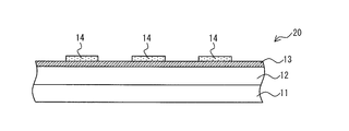
- the transfer film 20 includes a base film 11, a transfer binder layer 12, a sublimation ink layer 13, and a mask layer 14.
- the regions where the sublimation ink layer 13 and the mask layer 14 are formed are different between the transfer film 10 and the transfer film 20. That is, in the transfer film 10, the mask layer 14 is formed in the gap or outside of the sublimation ink layer 13 constituting the image. On the other hand, in the transfer film 20, a solid sublimation ink layer 13 is formed on the transfer binder layer 12, and a mask is formed on the sublimation ink layer 13 in a region where the sublimation ink is not transferred to the medium 100 to prevent the transfer. Layer 14 is formed.
- the mask layer 14 prevents the transfer of the sublimation ink in a region other than the region where transfer is desired. can do.
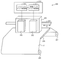
- FIG. 3 is a diagram schematically showing a configuration of an ink jet recording apparatus 200 which is an embodiment of the ink jet recording apparatus according to the present invention.
- the inkjet recording apparatus 200 is for making a transfer film according to the present invention by applying sublimation ink and a mask material to the transfer film sheet 11 ′ by inkjet.
- the transfer film sheet 11 ′ includes the base film 11 and the transfer binder layer 12 described above, and is mounted on the transfer binder layer 12 so that the sublimation ink and the mask material land.
- the inkjet recording apparatus 200 includes a carriage 201, a guide mechanism 204, a platen 205, a control unit 210, a driving roller 206, and a driven roller 207.
- the carriage 201 includes a sublimation ink head (first head) 202 and a UV ink head (second head) 203.
- the direction of movement of the carriage 201 is defined by the guide mechanism 204, and reciprocates in the direction of arrow X. As a result, the carriage 201 scans on the transfer film sheet 11 ′.
- the sublimation ink head 202 is a head for discharging a sublimation ink for forming an image and providing a sublimation ink layer on the transfer film sheet 11 ′.
- the carriage 201 scans the transfer film sheet 11 ′, sublimation ink is ejected from the sublimation ink head 202 based on predetermined image information.
- Ink ejection from the sublimation ink head 202 is controlled by a sublimation ink head control unit (first head control means) 211 described later.
- the UV ink head 203 is a head that discharges UV ink, which is a mask material, in order to provide a mask layer in a region where sublimation ink is not transferred to a preset medium.
- UV ink is ejected from the UV ink head 203 based on predetermined image information.
- Ink ejection from the UV ink head 203 is controlled by a UV ink head control unit (second head control means) 212 described later.
- the “UV ink” is an ink containing an ultraviolet curable resin.
- the ink jet recording apparatus 200 may include an ultraviolet irradiation unit for curing the UV ink.
- the sublimation ink head 202 that is a sublimation ink head and the UV ink head 203 that is a mask material head the mask layer of the transfer film according to the present invention is transferred.
- region in which the sublimation ink layer is not provided can be manufactured suitably.
- the mask layer can be formed while forming the sublimation ink layer on the transfer binder layer.
- the film according to the present invention can be manufactured in a very short time compared to the case of forming the mask layer.
- the guide mechanism 204 is a mechanism that regulates the moving direction of the carriage 201.
- the carriage 201 is attached to the guide mechanism 204 so that it can move in the direction of the arrow X, which is the length direction of the guide mechanism 204.
- the platen 205 is a table on which the transfer film sheet 11 ′ to be printed is placed. On the platen 205, the transfer film sheet 11 'receives the sublimation ink and the UV ink.
- the driving roller 206 moves the transfer film sheet 11 ′. Further, the transfer film sheet 11 ′ is moved by winding the transfer film sheet 11 ′ wound around a driven roller 207, which will be described later, by the drive roller 206.
- the driven roller 207 is for assisting the conveyance of the transfer film sheet 11 ′ by the driving roller 206.
- a transfer film sheet 11 ′ is wound around the driven roller 207, and the transfer film sheet 11 ′ is supplied to the side where the carriage 201 exists by rotating.
- the control unit 210 controls the operation of the ink jet recording apparatus 200.
- the control unit 210 includes a sublimation ink head control unit 211 and a UV ink head control unit 212.
- the sublimation ink head control unit 211 controls the sublimation ink head 202 so as to discharge sublimation ink based on image information indicating an image formed on the transfer film sheet 11 ′.
- the image information can be obtained, for example, by input from the user.
- the UV ink head control unit 212 controls the UV ink head 203 so as to eject UV ink so as to provide a mask layer in a region where the sublimation ink is not transferred to the medium.
- the specific control method is not particularly limited. For example, from the information indicating the image to be formed on the transfer film sheet 11 ′, an area where the sublimation ink is not printed is calculated to create information indicating the area where the UV ink is ejected, and based on the information, UV The UV ink head 203 may be controlled so as to eject ink. Alternatively, a user or the like may directly receive input of information indicating a region for ejecting UV ink, and the UV ink head 203 may be controlled to eject UV ink based on the information.
- the transfer film 10 is provided on the base film 11, the transfer binder layer 12 provided on the base film 11, and the transfer binder layer 12, for transferring to the medium 100 by sublimation ink.
- a sublimation ink layer 13 that is an image-formed layer; and a mask layer 14 provided in a region where the sublimation ink is not transferred to a preset medium 100.
- the transfer binder layer 12 is made of a material that penetrates when sublimation ink is sublimated.
- the ink fixing layer 15 As the sublimation ink penetrates into the transfer binder layer 12 and diffuses, the ink fixing layer 15 is formed. Even when the sublimation ink diffuses in the plane direction of the ink fixing layer 15 when transferring it to the medium 100, the transfer of the sublimation ink that has spread to the region is prevented by the mask layer 14. That is, since only the sublimation ink of the ink fixing layer only in a desired region is transferred onto the medium 100 by the mask layer 14, it is possible to prevent the outline of the image from being blurred. Therefore, even when sublimation ink is used and the ink fixing layer 15 is thickened, an image with no blurred outline can be formed on the transfer medium.
- the mask layer 14 is not provided and the solid image is printed up to the background of the image and then transferred to the fabric, the area transferred to the fabric increases, and the texture of the fabric is impaired. For example, even if the fabric is to be stretched or contracted, it is difficult to stretch or contract because the area where the image is printed is wide and the stretched state of the region is different from that of the fabric. This problem becomes more prominent when the ink fixing layer 15 is thicker. However, this embodiment can prevent this, so that the texture of the fabric is not impaired. In addition, since a background that is not originally required is not transferred, a good color as if an image was directly printed on the fabric can be obtained. Therefore, the texture of the fabric is not impaired and a transfer medium having a good color can be obtained.
- the mask layer 14 is provided on the transfer binder layer 12 in an area where the sublimation ink layer 13 is not provided.
- the amount of sublimation ink can be reduced as compared with the case where the sublimation ink layer 13 is solidly formed on the transfer binder layer 12.
- the mask layer 14 is formed on the sublimation ink layer 13 it is possible to increase the ink density in the region where the image of the sublimation ink layer 13 is formed. This is because if the mask layer 14 is formed adjacent to the sublimation ink layer 13, the mask layer 14 can prevent the ink from diffusing and spreading in the planar direction from the sublimation ink layer 13.
- the mask layer 14 can be formed while forming the sublimation ink layer 13 on the transfer binder layer 12 by inkjet, a transfer film can be easily produced.
- the adhesive strength between the transfer binder layer 12 and the mask layer 14 is stronger than the adhesive strength between the media 100 and the mask layer 14.
- the mask layer 14 can be peeled off together with the transfer film 10 after leaving an image on the medium 100.
- the mask layer 14 is formed of an ink containing an ultraviolet curable resin.
- the mask layer 14 can be easily peeled from the medium 100 when the transfer film 10 is peeled off after the transfer film 10 is pressure-bonded to the medium 100. .
- a transfer binder layer forming step in which a transfer binder layer 12 is provided on a base film 11, and a sublimation ink layer 13 that is an image layer is formed on the transfer binder layer 12 by sublimation ink.
- the transfer binder layer 12 is made of a material into which sublimation ink permeates when heat is applied.
- the ink fixing layer 15 As the sublimation ink penetrates into the transfer binder layer 12 and diffuses, the ink fixing layer 15 is formed. Even when the sublimation ink diffuses in the plane direction of the ink fixing layer 15 when this is transferred to the medium 100, the sublimation ink that has spread to the area is not transferred onto the medium 100 by the mask layer 14. That is, since only the sublimation ink of the ink fixing layer only in a desired region is transferred onto the medium 100 by the mask layer 14, it is possible to prevent the outline of the image from being blurred. Therefore, even when sublimation ink is used and the ink fixing layer 15 is thickened, an image with no blurred outline can be formed on the transfer medium.
- the mask layer 14 is cured so that the adhesive strength between the transfer binder layer 12 and the mask layer 14 is stronger than the adhesive strength between the media 100 and the mask layer 14. Includes a layer curing step.
- the mask layer 14 can be satisfactorily peeled from the medium 100 while leaving an image on the medium 100.
- the mask layer 14 is formed of an ink containing an ultraviolet curable resin.
- the sublimation ink is formed by an ink jet recording apparatus. While forming the layer 13, the mask layer 14 is formed.
- the sublimation ink layer 13 and the mask layer 14 can be simultaneously formed with one ink jet recording apparatus. Therefore, the transfer film according to the present invention can be manufactured in a shorter time and easily.
- the sublimation ink layer 13 and the mask layer 14 are pressure-bonded to the medium 100 in the transfer step
- the sublimation ink layer 13 and the transfer binder layer 12 are heated to transfer the sublimation ink to the transfer binder. More preferably, it penetrates the layer.
- the sublimation ink permeates and diffuses into the transfer binder layer positioned immediately above, thereby forming an ink fixing layer 15 that is a transfer binder layer containing the sublimation ink, and this forms a transfer image.
- the ink jet recording apparatus 200 is provided with a sublimation ink head 202 that discharges sublimation ink for forming an image to provide the sublimation ink layer 13 and a mask layer 14 in a region where the sublimation ink is not transferred to a preset medium 100.
- a UV ink head 203 for discharging the mask material
- a sublimation ink head control unit 211 for controlling the sublimation ink head 202 so as to discharge the sublimation ink based on image information indicating an image, and discharging the mask material to the region.
- a UV ink head controller 212 for controlling the UV ink head 203 as described above. According to this configuration, the transfer film 10 can be easily manufactured.
- the present invention can be used for printing an image on a cloth such as clothing and bag.
Landscapes
- Engineering & Computer Science (AREA)
- Textile Engineering (AREA)
- Decoration By Transfer Pictures (AREA)
- Ink Jet Recording Methods And Recording Media Thereof (AREA)
- Impression-Transfer Materials And Handling Thereof (AREA)
- Coloring (AREA)
Description
本発明は、基材から画像を被転写媒体に転写するための転写フィルム、転写方法及びインクジェット記録装置に関する。
特許文献1には、印刷用メディアを加熱して昇華性染料インクをメディア本体の表面に拡散・発色させて画像を形成する方法が記載されている。
インク受像シートに含浸された昇華性染料は、インク定着層が厚いと平面方向にも拡散して、画像の輪郭がぼやける。インク定着層を薄くすることで昇華性染料の平面方向への拡散の防止を図ることも考えられる。しかし、インク定着層を薄くすると、画像を形成する対象であるメディアが布帛のように目が粗い素材の場合、繊維と繊維との間に跨るようにインク定着層を形成することができない。そのため、画質が低下するという問題がある。
本発明はこのような問題に鑑みて成されたものであり、昇華インクを用い、インク定着層を厚くする場合であっても、輪郭がぼやけない画像を被転写媒体上に形成することを目的とする。
本発明に係る転写フィルムは、基材と、上記基材上に設けられた転写バインダ層と、上記転写バインダ層上に設けられ、昇華インクによって被転写媒体に転写するための画像を形成した層である昇華インク層と、予め設定された上記被転写媒体に上記昇華インクを転写しない領域に設けられた、マスク層と、を備え、上記転写バインダ層は、上記昇華インクが昇華することにより浸透する材料で構成されている。
昇華インクが転写バインダ層に浸透して拡散することにより、インク定着層が形成される。これを被転写媒体に転写する際に、インク定着層の平面方向に昇華インクが拡散していたとしても、上記領域にまで滲んだ昇華インクの転写はマスク層により防がれる。つまり、マスク層により所望の領域のみのインク定着層の昇華インクのみが被転写媒体上に転写されるため、画像の輪郭がぼやけることを防ぐことができる。よって、昇華インクを用い、インク定着層を厚くする場合であっても、輪郭がぼやけない画像を被転写媒体上に形成することができる。
また、仮にマスク層を設けずに、画像の背景までベタで印刷した後これを布帛に転写すると、布帛に転写される領域が大きくなり、布帛の質感が損なわれる。例えば、布帛を伸縮させようとしても、画像を印刷した領域が広く、且つ、当該領域の伸縮具合が当該布帛と異なるため、伸縮させにくい。この問題はインク定着層が厚くなるとより顕著である。しかし、本発明ではこれを防ぐことができるので、布帛の質感が損なわれない。また、本来必要のない背景が転写されることが無いため、布帛に直接画像が印刷されたような良好な色彩を得ることができる。よって、布帛の質感が損なわれず、良い色彩の被転写媒体を得ることができる。
本発明に係る転写フィルムでは、上記マスク層は、上記転写バインダ層上であって、上記昇華インク層が設けられていない領域に設けられていることがより好ましい。
インクジェットによって、転写バインダ層上に昇華インク層を形成しながらマスク層をも形成できるため、容易に転写フィルムを作製できる。また、昇華インク層を上記転写バインダ層上にベタで形成する場合に比べて、昇華インクの量を少なくできる。また、マスク層を昇華インク層の上に形成する場合に比べて、昇華インク層の画像を形成する領域のインクの濃度を高くすることができる。昇華インク層に隣接してマスク層が形成されていると、昇華インク層から平面方向へインクが拡散して滲むことをマスク層によって防止できるからである。
本発明に係る転写フィルムでは、上記被転写媒体と上記マスク層との接着強度より、上記転写バインダ層と上記マスク層との接着強度の方が強いことがより好ましい。
転写フィルムを被転写媒体に圧着した後に転写フィルムを剥がす際に、画像を被転写媒体に残した上で、マスク層を良好に転写フィルムと共に剥がすことができる。
本発明に係る転写フィルムでは、上記マスク層は紫外線硬化型樹脂を含むインクにより形成されていることがより好ましい。
紫外線を照射して、マスク層を硬化させておくことにより、転写フィルムを被転写媒体に圧着した後に転写フィルムを剥がす際に、マスク層を被転写媒体から容易に剥がすことが容易となる。
本発明に係る転写方法は、被転写媒体に画像を転写する転写方法であって、基材上に転写バインダ層を設ける転写バインダ層形成工程と、上記転写バインダ層上に昇華インクによって上記画像の層である昇華インク層を形成する昇華インク層形成工程と、上記被転写媒体上に上記昇華インクを転写しない領域にマスク層を設けるマスク層形成工程と、上記昇華インク層及び上記マスク層を上記被転写媒体に圧着して上記画像を転写する転写工程と、を含み、上記転写バインダ層は、熱を加えることにより上記昇華インクが浸透する材料で構成されている。
昇華インクが転写バインダ層に浸透して拡散することにより、インク定着層が形成される。これを被転写媒体に転写する際に、インク定着層の平面方向に昇華インクが拡散していたとしても、上記領域にまで滲んだ昇華インクはマスク層によって被転写媒体上に転写されない。つまり、マスク層により所望の領域のみのインク定着層の昇華インクのみが被転写媒体上に転写されるため、画像の輪郭がぼやけることを防ぐことができる。よって、昇華インクを用い、インク定着層を厚くする場合であっても、輪郭がぼやけない画像を被転写媒体上に形成することができる。
本発明に係る転写方法では、上記被転写媒体と上記マスク層との接着強度より、上記転写バインダ層と上記マスク層との接着強度の方が強くなるように上記マスク層を硬化させるマスク層硬化工程を含むことがより好ましい。
転写フィルムを被転写媒体に圧着した後に転写フィルムを剥がす際に、画像を被転写媒体に残した上で、マスク層を良好に被転写媒体から剥がすことができる。
本発明に係る転写方法では、上記マスク層は、紫外線硬化型樹脂を含むインクにより形成されるものであり、上記昇華インク層形成工程及び上記マスク層形成工程では、インクジェット記録装置によって上記昇華インク層を形成しながら、上記マスク層を形成することがより好ましい。
昇華インク層とマスク層とを一つのインクジェット記録装置で同時に作ることができる。よって、より短時間且つ容易に本発明に係る転写フィルムを製造することができる。
本発明に係る転写方法では、上記転写工程において上記昇華インク層及び上記マスク層を上記被転写媒体に圧着した後に、上記昇華インク層及び上記転写バインダ層を加熱して、上記昇華インクを上記転写バインダ層に浸透させることがより好ましい。
昇華インクはその直上に位置する転写バインダ層に浸透して拡散することにより、昇華インクを含む転写バインダ層であるインク定着層が形成され、これが転写画像を形成する。
本発明に係るインクジェット記録装置は、画像を形成するための昇華インクを吐出して、昇華インク層を設ける第一のヘッドと、予め設定された上記被転写媒体に上記昇華インクを転写しない領域にマスク層を設けるためのマスク材料を吐出する第二のヘッドと、上記画像を示す画像情報に基づいて上記昇華インクを吐出するように上記第一のヘッドを制御する第一のヘッド制御手段と、上記領域に上記マスク材料を吐出するように上記第二のヘッドを制御する第二のヘッド制御手段と、を備える。
この構成によれば、本発明に係る転写フィルムを容易に製造することができる。
本発明によれば、昇華インクを用い、インク定着層を厚くする場合であっても、輪郭がぼやけない画像を被転写媒体上に形成することができるという効果を奏する。
<転写フィルム及び転写方法>
以下、本発明の実施の形態について詳細に説明する。まず、図1A~図1Dを用いて、本発明に係る転写フィルム及び転写方法の一実施形態について説明する。図1A~図1Dは本発明に係る転写方法の一実施形態の手順を示す図である。
以下、本発明の実施の形態について詳細に説明する。まず、図1A~図1Dを用いて、本発明に係る転写フィルム及び転写方法の一実施形態について説明する。図1A~図1Dは本発明に係る転写方法の一実施形態の手順を示す図である。
本実施形態では、まず転写フィルム10を製造し、メディア(被転写媒体)100に転写フィルム10で画像を形成している昇華インクを転写することによりメディア100上に画像を印刷する。
メディア100の具体例としては、例えば、布帛が好適に用いられる。つまり、本発明に係る転写フィルムは布帛への転写により適している。布帛のように目が粗いメディアの場合、インク定着層は厚いことが好ましい。繊維と繊維との間に跨るようにインク定着層を形成することにより、画質が低下することを防ぐことができるからである。一方、インク定着層を厚くすると昇華インクが平面方向に拡散して輪郭がぼやけるという問題を従来技術は抱えている。しかり、本発明はこの問題を解決できる。例えば、本実施形態では、昇華インクが後述する転写バインダ層12に浸透して拡散することにより、インク定着層が形成される。これをメディア100に転写する際に、インク定着層の平面方向に昇華インクが拡散していたとしても、滲んだ昇華インクのメディア100上への転写はマスク層14により防がれる。つまり、マスク層14により所望の領域のみのインク定着層の昇華インクのみがメディア100上に転写されるため、画像の輪郭がぼやけることを防ぐことができる。よって、昇華インクを用い、インク定着層を厚くする場合であっても、輪郭がぼやけない画像を被転写媒体上に形成することができる。
また、布帛の質感が損なわれず、良い色彩の被転写媒体を得ることができるという利点もある。つまり、マスク層14によって、後述する昇華インク層13がベタでメディア100上に転写させることを防ぐことができる。仮にマスク層14を設けずに、画像の背景までベタで印刷した後これを布帛に転写すると、布帛に転写される領域が大きくなり、布帛の質感が損なわれる。例えば、布帛を伸縮させようとしても、画像を印刷した領域が広く、且つ、当該領域の伸縮具合が当該布帛と異なるため、伸縮させにくい。しかし、本発明ではこれを防ぐことができるので、布帛の質感が損なわれない。また、本来必要のない背景が転写されることが無いため、布帛に直接画像が印刷されたような良好な色彩を得ることができる。
まず、図1Aに示すように、基材フィルム(基材)11上に転写バインダ層12を設ける(転写バインダ層作製工程)。基材フィルム11の表面には後述のインク定着層15からインクが染み出すことを防止するコーティング剤を予め塗布しておくことがより好ましい。転写後にコーティング剤がインク定着層15の表面を被覆することになり、印刷物の表面にインクが染み出すことを防止することができる。
転写バインダ層12は、基材フィルム11と昇華インク層13及びマスク層14とを結合するための層である。後述する昇華インク層13の昇華インクが昇華することで、昇華した当該昇華インクが当該転写バインダ層12の中に浸透して拡散する材料で構成されている。例えば、本発明に係る転写フィルムが備える転写バインダ層はウレタン;NBR、SBR、IP(イソプレン)等のゴム等の材料で構成すればよい。昇華インクを昇華させる方法は、昇華インクの種類によって適宜選択すればよく、例えば、昇華インク層13を加熱してもよく、加圧してもよい。本実施形態では加熱することにより昇華インクを昇華させる場合について説明する。昇華インクが浸透して転写後の画像を形成するので、転写バインダ層12は、転写後の画像に厚みをもたせるための層であるともいえる。
転写バインダ層12を設ける方法は、特に限定されず、例えば、従来公知の方法で、基材フィルム11上に転写バインダ層12の材料を塗布すればよい。
次に、図1Bに示すように、昇華インク層13及びマスク層14を設ける(昇華インク層作製工程、マスク層作製工程)。
昇華インク層13は昇華インクを含む層であり、メディア100に転写する画像を形成している。昇華インクは昇華性を有するインクであり、熱を加えることで昇華する。本実施形態においては、昇華すると転写バインダ層12内に浸透して、拡散する。これにより転写バインダ層12がインク定着層15に変化する。インク定着層15とは、メディア100にインクを定着させるための層である。
マスク層14は、メディア100上に昇華インクを転写しない領域である、予め定められた領域に設けられた層である。マスク層14のある領域においては、昇華インク(より、正確には後述する昇華インク拡散層15)はメディア100上に転写されない。マスク層14を構成するマスク材料は、昇華インクの転写を防ぐものであればよいが、例えば、紫外線硬化型樹脂を含むインクが挙げられる。
また、図1Bに示されるように、マスク層14は、転写バインダ層12上であって、昇華インク層13が設けられていない領域に設けられている。つまり、昇華インクによって必要な画像のみを印刷し、背景等は印刷せず、画像の周囲や画像における昇華インクによって形成された領域の隙間にマスク層14が設けられる。このように、昇華インク層13もマスク層14も転写バインダ層12上に設けることで、転写フィルム10を製造しやすい。つまり、昇華インク及びマスク材料をインクジェットによって共に吐出することで、昇華インク層13を設けながらマスク層14を設けることができる。
つまり、昇華インク層13及びマスク層14を設ける方法としては、特に限定されないが、インクジェット記録装置によりインクジェットで設けることがより好ましい。インクジェット記録装置に、昇華インク及びマスク材料を吐出するヘッドをそれぞれ設けておけば、同じパスで、昇華インク層13を形成しながら、マスク層14を形成することができる。これにより、転写フィルム10をより短時間で、且つ、簡単に製造することができる。
次に、紫外線を照射してマスク層14を硬化する(マスク層硬化工程)。これにより、メディア100とマスク層14との接着強度より、転写バインダ層12とマスク層14との接着強度の方が強くなる。これは、後で転写フィルム10を圧着した後に剥がすときに、マスク層14をメディア100上から剥がしやすくするためである。つまり、マスク層14はメディア100に対してよりも転写バインダ層12に対してより強い強度で接着されているので、メディア100から剥がれやすい。
以上により、本発明に係る転写フィルムの一実施形態である転写フィルム10が製造される。
次に、図1Cに示すように、転写フィルム10をメディア100に圧着して画像を転写する(転写工程)。ここで、昇華インク層13及びマスク層14をメディア100に圧着した後に、昇華インク層13及び転写バインダ層12を加熱して、昇華インクを転写バインダ層12に浸透させる。これにより、昇華インク層13の直上の転写バインダ層12に昇華インクが拡散して、図1Dに示すインク定着層15が形成される。なお、ここで、昇華インクはインク定着層15の平面方向に滲む虞があるが、マスク層14によって滲んだ領域の昇華インクはメディア100上には転写されない。よって、メディア100上に形成される画像の輪郭がぼやけない。加熱の温度は、昇華インク及び転写バインダ層12を構成する材料に応じて適宜設定され得る。
転写バインダ層12及び昇華インク層13の加熱温度としては、昇華インクが昇華する温度である限り限定されない。
また、マスク層14は予めマスク層硬化工程にて硬化されており、メディア100に対する接着強度は、転写バインダ層12に対する接着強度より弱くなっている。従って、昇華インク層13、ひいては加熱された後のインク定着層15はメディア100に接着するが、マスク層14は後述の剥離により剥がれやすくなっている。
次に、図1Dに示すように、転写フィルム10をメディア100から剥離する。このとき、インク定着層15はメディア100上に残って画像を形成する。一方、マスク層14とメディア100との接着強度より、マスク層14と転写バインダ層12との接着強度の方がより強いので、マスク層14はメディア100上には残らず、基材フィルム11及び転写バインダ層12と共に剥離される。
以上により、メディア100上に画像が形成される。
〔変形例〕
次に図2を用いて、本発明に係る転写フィルムの転写フィルム10とは異なる変形例について説明する。
次に図2を用いて、本発明に係る転写フィルムの転写フィルム10とは異なる変形例について説明する。
転写フィルム20は、基材フィルム11、転写バインダ層12、昇華インク層13、マスク層14を備えている。
転写フィルム10と転写フィルム20とでは、昇華インク層13及びマスク層14が形成されている領域が異なる。つまり、転写フィルム10では、画像を構成する昇華インク層13の隙間や外側にマスク層14が形成されている。一方、転写フィルム20では、転写バインダ層12の上にベタに昇華インク層13が形成されており、メディア100に昇華インクを転写しない領域の昇華インク層13上に、その転写を防ぐようにマスク層14が形成されている。
これにより、昇華インクが拡散していても、転写を所望する領域以外の昇華インクの転写をマスク層14が防ぐので、転写フィルム10と同様に、輪郭がぼやけていない画像をメディア100上に形成することができる。
<インクジェット記録装置>
次に、本発明に係るインクジェット記録装置の一実施形態について図3を用いて説明する。図3は本発明に係るインクジェット記録装置の一実施形態であるインクジェット記録装置200の構成を模式的に示す図である。
次に、本発明に係るインクジェット記録装置の一実施形態について図3を用いて説明する。図3は本発明に係るインクジェット記録装置の一実施形態であるインクジェット記録装置200の構成を模式的に示す図である。
インクジェット記録装置200は、転写フィルム用シート11’に昇華インク及びマスク材料をインクジェットにより塗布して、本発明に係る転写フィルムを作るためのものである。転写フィルム用シート11’は、上述の基材フィルム11及び転写バインダ層12により構成されており、転写バインダ層12上に昇華インク及びマスク材料が着弾するように搭載されている。
インクジェット記録装置200は、キャリッジ201、ガイド機構204、プラテン205、制御部210、駆動ローラ206、従動ローラ207を備えている。
キャリッジ201は、昇華インクヘッド(第一のヘッド)202、UVインクヘッド(第二のヘッド)203を備えている。
キャリッジ201はガイド機構204により移動する方向が規定されており、矢印X方向に往復移動する。これにより、キャリッジ201は転写フィルム用シート11’上を走査する。
昇華インクヘッド202は、画像を形成するための昇華インクを吐出して転写フィルム用シート11’上に昇華インク層を設けるためのヘッドである。キャリッジ201が転写フィルム用シート11’上を走査する際に、所定の画像情報に基づいて、昇華インクヘッド202から昇華インクが吐出される。昇華インクヘッド202からのインクの吐出は後述の昇華インクヘッド制御部(第一のヘッド制御手段)211により制御される。
UVインクヘッド203は、予め設定されたメディアに昇華インクを転写しない領域にマスク層を設けるために、マスク材料であるUVインクを吐出するヘッドである。キャリッジ201が転写フィルム用シート11’上を走査する際に、所定の画像情報に基づいて、UVインクヘッド203からUVインクが吐出される。UVインクヘッド203からのインクの吐出は後述のUVインクヘッド制御部(第二のヘッド制御手段)212により制御される。なお、「UVインク」とは紫外線硬化型樹脂を含むインクである。インクジェット記録装置200はUVインクを硬化させるための紫外線照射手段を備えていてもよい。
このように、昇華インク用のヘッドである昇華インクヘッド202及びマスク材料用のヘッドであるUVインクヘッド203の二種類のヘッドを備えることにより、本発明に係る転写フィルムのうち、マスク層が転写バインダ層上であって、昇華インク層が設けられていない領域に設けられている形態のものを好適に製造することができる。
つまり、昇華インクを吐出しながら、UVインクを吐出することにより、転写バインダ層上に昇華インク層を形成しながら、マスク層を形成することができる。昇華インク層が形成し終わってから、マスク層を形成する場合に比べて極めて短時間で本発明に係るフィルムを製造することができる。
ガイド機構204はキャリッジ201の移動方向を規定する機構である。ガイド機構204の長さ方向である矢印X方向に移動できるように、キャリッジ201はガイド機構204に取り付けられている。
プラテン205は、印刷対象である転写フィルム用シート11’を載置するための台である。プラテン205上において、転写フィルム用シート11’は昇華インク及びUVインクの吐出を受ける。
駆動ローラ206は転写フィルム用シート11’を移動させるものである。また、後述する従動ローラ207に巻きつけられた転写フィルム用シート11’を駆動ローラ206が巻き取ることによって、転写フィルム用シート11’が移動する。
従動ローラ207は、駆動ローラ206による転写フィルム用シート11’の搬送を補助するためのものである。従動ローラ207には、転写フィルム用シート11’が巻きつけられており、回転させることによって転写フィルム用シート11’をキャリッジ201のある方へ供給する。
制御部210は、インクジェット記録装置200の動作を制御するものである。制御部210は、昇華インクヘッド制御部211、UVインクヘッド制御部212を備えている。
昇華インクヘッド制御部211は、転写フィルム用シート11’上に形成する画像を示す画像情報に基づいて昇華インクを吐出するように、昇華インクヘッド202を制御する。画像情報は、例えば、ユーザからの入力等によって得ることができる。
UVインクヘッド制御部212は、メディアに昇華インクを転写しない領域にマスク層を設けるようにUVインクを吐出するようにUVインクヘッド203を制御する。
具体的な制御方法としては、特に限定されない。例えば、転写フィルム用シート11’上に形成する画像を示す情報から、昇華インクが印刷されない領域を演算して、UVインクを吐出する領域を示す情報を作成して、当該情報に基づいて、UVインクを吐出するようにUVインクヘッド203を制御してもよい。また、ユーザ等により、直接、UVインクを吐出する領域を示す情報の入力を受け付けて、当該情報に基づいて、UVインクを吐出するようにUVインクヘッド203を制御してもよい。
本発明は上述した各実施形態に限定されるものではなく、請求項に示した範囲で種々の変更が可能であり、異なる実施形態にそれぞれ開示された技術的手段を適宜組み合わせて得られる実施形態についても本発明の技術的範囲に含まれる。
<付記事項>
以上のように、転写フィルム10は、基材フィルム11と、基材フィルム11上に設けられた転写バインダ層12と、転写バインダ層12上に設けられ、昇華インクによってメディア100に転写するための画像を形成した層である昇華インク層13と、予め設定されたメディア100に昇華インクを転写しない領域に設けられたマスク層14と、を備える。転写バインダ層12は、昇華インクが昇華することにより浸透する材料で構成されている。
以上のように、転写フィルム10は、基材フィルム11と、基材フィルム11上に設けられた転写バインダ層12と、転写バインダ層12上に設けられ、昇華インクによってメディア100に転写するための画像を形成した層である昇華インク層13と、予め設定されたメディア100に昇華インクを転写しない領域に設けられたマスク層14と、を備える。転写バインダ層12は、昇華インクが昇華することにより浸透する材料で構成されている。
昇華インクが転写バインダ層12に浸透して拡散することにより、インク定着層15が形成される。これをメディア100に転写する際に、インク定着層15の平面方向に昇華インクが拡散していたとしても、上記領域にまで滲んだ昇華インクの転写はマスク層14により防がれる。つまり、マスク層14により所望の領域のみのインク定着層の昇華インクのみがメディア100上に転写されるため、画像の輪郭がぼやけることを防ぐことができる。よって、昇華インクを用い、インク定着層15を厚くする場合であっても、輪郭がぼやけない画像を被転写媒体上に形成することができる。
また、仮にマスク層14を設けずに、画像の背景までベタで印刷した後これを布帛に転写すると、布帛に転写される領域が大きくなり、布帛の質感が損なわれる。例えば、布帛を伸縮させようとしても、画像を印刷した領域が広く、且つ、当該領域の伸縮具合が当該布帛と異なるため、伸縮させにくい。この問題はインク定着層15が厚くなるとより顕著である。しかし、本実施形態ではこれを防ぐことができるので、布帛の質感が損なわれない。また、本来必要のない背景が転写されることが無いため、布帛に直接画像が印刷されたような良好な色彩を得ることができる。よって、布帛の質感が損なわれず、良い色彩の被転写媒体を得ることができる。
転写フィルム10では、マスク層14は、転写バインダ層12上であって、昇華インク層13が設けられていない領域に設けられている。また、昇華インク層13を転写バインダ層12上にベタで形成する場合に比べて、昇華インクの量を少なくできる。また、マスク層14を昇華インク層13の上に形成する場合に比べて、昇華インク層13の画像を形成する領域のインクの濃度を高くすることができる。昇華インク層13に隣接してマスク層14が形成されていると、昇華インク層13から平面方向へインクが拡散して滲むことをマスク層14によって防止できるからである。
インクジェットによって、転写バインダ層12上に昇華インク層13を形成しながらマスク層14をも形成できるため、容易に転写フィルムを作製できる。
転写フィルム10では、メディア100とマスク層14との接着強度より、転写バインダ層12とマスク層14との接着強度の方が強い。
転写フィルム10をメディア100に圧着した後に転写フィルム10を剥がす際に、画像をメディア100に残した上で、マスク層14を良好に転写フィルム10と共に剥がすことができる。
転写フィルム10では、マスク層14は紫外線硬化型樹脂を含むインクにより形成されている。
紫外線を照射して、マスク層14を硬化させておくことにより、転写フィルム10をメディア100に圧着した後に転写フィルム10を剥がす際に、マスク層14をメディア100から容易に剥がすことが容易となる。
本発明に係る転写方法の一実施形態は、基材フィルム11上に転写バインダ層12を設ける転写バインダ層形成工程と、転写バインダ層12上に昇華インクによって画像の層である昇華インク層13を形成する昇華インク層形成工程と、メディア100上に昇華インクを転写しない領域にマスク層14を設けるマスク層形成工程と、昇華インク層13及びマスク層14をメディア100に圧着して画像を転写する転写工程と、を含む。転写バインダ層12は、熱を加えることにより昇華インクが浸透する材料で構成されている。
昇華インクが転写バインダ層12に浸透して拡散することにより、インク定着層15が形成される。これをメディア100に転写する際に、インク定着層15の平面方向に昇華インクが拡散していたとしても、当該領域にまで滲んだ昇華インクはマスク層14によってメディア100上に転写されない。つまり、マスク層14により所望の領域のみのインク定着層の昇華インクのみがメディア100上に転写されるため、画像の輪郭がぼやけることを防ぐことができる。よって、昇華インクを用い、インク定着層15を厚くする場合であっても、輪郭がぼやけない画像を被転写媒体上に形成することができる。
本発明に係る転写方法の一実施形態では、メディア100とマスク層14との接着強度より、転写バインダ層12とマスク層14との接着強度の方が強くなるようにマスク層14を硬化させるマスク層硬化工程を含む。
転写フィルム10をメディア100に圧着した後に転写フィルム10を剥がす際に、画像をメディア100に残した上で、マスク層14を良好にメディア100から剥がすことができる。
本発明に係る転写方法の一実施形態では、マスク層14は、紫外線硬化型樹脂を含むインクにより形成されるものであり、昇華インク層形成工程及びマスク層形成工程では、インクジェット記録装置によって昇華インク層13を形成しながら、マスク層14を形成する。
昇華インク層13とマスク層14とを一つのインクジェット記録装置で同時に作ることができる。よって、より短時間且つ容易に本発明に係る転写フィルムを製造することができる。
本発明に係る転写方法の一実施形態では、転写工程において昇華インク層13及びマスク層14をメディア100に圧着した後に、昇華インク層13及び転写バインダ層12を加熱して、昇華インクを転写バインダ層に浸透させることがより好ましい。
昇華インクはその直上に位置する転写バインダ層に浸透して拡散することにより、昇華インクを含む転写バインダ層であるインク定着層15が形成され、これが転写画像を形成する。
インクジェット記録装置200は、画像を形成するための昇華インクを吐出して昇華インク層13を設ける昇華インクヘッド202と、予め設定されたメディア100に昇華インクを転写しない領域にマスク層14を設けるためのマスク材料を吐出するUVインクヘッド203と、画像を示す画像情報に基づいて昇華インクを吐出するように昇華インクヘッド202を制御する昇華インクヘッド制御部211と、上記領域にマスク材料を吐出するようにUVインクヘッド203を制御するUVインクヘッド制御部212と、を備える。この構成によれば、転写フィルム10を容易に製造することができる。
本発明は、衣類、鞄等の布帛への画像の印刷に利用することができる。
Claims (9)
- 基材と、
上記基材上に設けられた転写バインダ層と、
上記転写バインダ層上に設けられ、昇華インクによって被転写媒体に転写するための画像を形成した層である昇華インク層と、
予め設定された上記被転写媒体に上記昇華インクを転写しない領域に設けられた、マスク層と、
を備え、
上記転写バインダ層は、上記昇華インクが昇華することにより浸透する材料で構成されている転写フィルム。 - 上記マスク層は、上記転写バインダ層上であって、上記昇華インク層が設けられていない領域に設けられている、請求項1に記載の転写フィルム。
- 上記被転写媒体と上記マスク層との接着強度より、上記転写バインダ層と上記マスク層との接着強度の方が強い、請求項1に記載の転写フィルム。
- 上記マスク層は紫外線硬化型樹脂を含むインクにより形成されている、請求項1に記載の転写フィルム。
- 被転写媒体に画像を転写する転写方法であって、
基材上に転写バインダ層を設ける転写バインダ層作製工程と、
上記転写バインダ層上に昇華インクによって被転写媒体に転写する画像を形成した層である昇華インク層を設ける昇華インク層作製工程と、
上記被転写媒体上に上記昇華インクを転写しない領域にマスク層を設けるマスク層作製工程と、
上記昇華インク層及び上記マスク層を上記被転写媒体に圧着して上記画像を転写する転写工程と、を含み、上記転写バインダ層は、熱を加えることにより上記昇華インクが浸透する材料で構成されている、転写方法。 - 上記被転写媒体と上記マスク層との接着強度より、上記転写バインダ層と上記マスク層との接着強度の方が強くなるように上記マスク層を硬化させるマスク層硬化工程を含む請求項5に記載の転写方法。
- 上記マスク層は、紫外線硬化型樹脂を含むインクにより形成されるものであり、
上記昇華インク層作製工程及び上記マスク層作製工程では、インクジェット記録装置によって上記昇華インク層を形成しながら、上記マスク層を形成する、請求項5に記載の転写方法。 - 上記転写工程において上記昇華インク層及び上記マスク層を上記被転写媒体に圧着した後に、上記昇華インク層及び上記転写バインダ層を加熱して、上記昇華インクを上記転写バインダ層に浸透させる、請求項5に記載の転写方法。
- 画像を形成するための昇華インクを吐出して、昇華インク層を設ける第一のヘッドと、
予め設定された被転写媒体に上記昇華インクを転写しない領域にマスク層を設けるためのマスク材料を吐出する第二のヘッドと、
上記画像を示す画像情報に基づいて上記昇華インクを吐出するように上記第一のヘッドを制御する第一のヘッド制御手段と、
上記領域に上記マスク材料を吐出するように上記第二のヘッドを制御する第二のヘッド制御手段と、を備えるインクジェット記録装置。
Priority Applications (3)
| Application Number | Priority Date | Filing Date | Title |
|---|---|---|---|
| EP13764418.3A EP2829414A4 (en) | 2012-03-19 | 2013-03-05 | TRANSFER FILM, TRANSFER METHOD AND INK IRRIGATION DEVICE |
| CN201380014277.3A CN104203592A (zh) | 2012-03-19 | 2013-03-05 | 转印膜、转印方法及喷墨记录装置 |
| US14/382,320 US9688065B2 (en) | 2012-03-19 | 2013-03-05 | Transfer film, transfer method and inkjet recording apparatus |
Applications Claiming Priority (2)
| Application Number | Priority Date | Filing Date | Title |
|---|---|---|---|
| JP2012062720A JP6305675B2 (ja) | 2012-03-19 | 2012-03-19 | 転写フィルム及び転写方法 |
| JP2012-062720 | 2012-03-19 |
Publications (1)
| Publication Number | Publication Date |
|---|---|
| WO2013141019A1 true WO2013141019A1 (ja) | 2013-09-26 |
Family
ID=49222481
Family Applications (1)
| Application Number | Title | Priority Date | Filing Date |
|---|---|---|---|
| PCT/JP2013/056033 Ceased WO2013141019A1 (ja) | 2012-03-19 | 2013-03-05 | 転写フィルム、転写方法及びインクジェット記録装置 |
Country Status (5)
| Country | Link |
|---|---|
| US (1) | US9688065B2 (ja) |
| EP (1) | EP2829414A4 (ja) |
| JP (1) | JP6305675B2 (ja) |
| CN (1) | CN104203592A (ja) |
| WO (1) | WO2013141019A1 (ja) |
Families Citing this family (7)
| Publication number | Priority date | Publication date | Assignee | Title |
|---|---|---|---|---|
| CN106457880A (zh) * | 2014-04-07 | 2017-02-22 | 艾利丹尼森零售信息服务公司 | 在用于具体活动的具体商业制品上使用的热转印和方法 |
| JP6558801B2 (ja) * | 2015-10-29 | 2019-08-14 | 株式会社ミマキエンジニアリング | 染色方法 |
| JP6587283B2 (ja) * | 2015-10-29 | 2019-10-09 | 株式会社ミマキエンジニアリング | 染色方法 |
| US10908548B2 (en) | 2016-03-02 | 2021-02-02 | Hp Indigo B.V. | Selective printing |
| JP6260878B2 (ja) | 2016-05-27 | 2018-01-17 | 株式会社アイエヌジー | 画像転写シート、画像転写シートの製造方法、画像転写方法 |
| JP6795474B2 (ja) * | 2017-08-30 | 2020-12-02 | 株式会社ミマキエンジニアリング | 印刷物作成方法及び印刷物 |
| JP2025163450A (ja) * | 2024-04-17 | 2025-10-29 | 株式会社ミマキエンジニアリング | 画像転写方法、非転写領域形成装置、印刷システム、及び転写媒体管理方法 |
Citations (5)
| Publication number | Priority date | Publication date | Assignee | Title |
|---|---|---|---|---|
| JPS4957189A (ja) * | 1972-10-07 | 1974-06-03 | ||
| JPS6250971U (ja) * | 1985-09-17 | 1987-03-30 | ||
| JPH02154083A (ja) * | 1988-12-02 | 1990-06-13 | Toppan Printing Co Ltd | 着色エンボス加工法 |
| JP2002210943A (ja) | 2001-01-22 | 2002-07-31 | Seiko Epson Corp | 画像形成方法、これに用いる印刷用メディアおよびシートカートリッジ |
| JP2003063198A (ja) * | 2001-08-24 | 2003-03-05 | Seiko Epson Corp | 画像形成方法および画像形成装置 |
Family Cites Families (24)
| Publication number | Priority date | Publication date | Assignee | Title |
|---|---|---|---|---|
| US4021591A (en) * | 1974-12-04 | 1977-05-03 | Roy F. DeVries | Sublimation transfer and method |
| JPS6024867B2 (ja) * | 1978-06-15 | 1985-06-14 | 株式会社松井色素化学工業所 | 染料昇華転写捺染法 |
| JPH02171276A (ja) * | 1988-12-23 | 1990-07-02 | Nichiwa Insatsu Kk | 多品種少量用昇華転写方法 |
| US5741387A (en) * | 1995-08-15 | 1998-04-21 | Riverside Industries, Inc. | Lithographic printing process and transfer sheet |
| JPH10315639A (ja) * | 1997-05-16 | 1998-12-02 | Dainippon Printing Co Ltd | 受容層転写シートおよびカード状印画物 |
| CA2361546C (en) * | 1999-02-03 | 2008-10-14 | Contra Vision Limited | Partial imaging of a substrate with superimposed layers |
| US6486903B1 (en) * | 2000-09-27 | 2002-11-26 | Sawgrass Systems, Inc. | Transfer printing process |
| CA2473334A1 (en) * | 2002-01-23 | 2003-07-31 | Contra Vision Ltd. | Printing with differential adhesion |
| US6540345B1 (en) * | 2002-03-12 | 2003-04-01 | Sawgrass Systems, Inc. | Transfer printing process |
| TWI273991B (en) * | 2002-05-15 | 2007-02-21 | Kiwa Chemical Ind Co Ltd | Laminate for printing and printing method and printed matter using the same |
| US6832832B2 (en) * | 2002-09-04 | 2004-12-21 | Nu-Kote International, Inc. | Dye sublimation ink-jet ink and dye sublimation transfer process using the same |
| US6909444B2 (en) * | 2002-09-09 | 2005-06-21 | Dai Nippon Printing Co., Ltd. | Transfer ribbon, image expressing medium and method for production of them |
| US7393576B2 (en) * | 2004-01-16 | 2008-07-01 | High Voltage Graphics, Inc. | Process for printing and molding a flocked article |
| WO2005118948A2 (en) * | 2004-05-26 | 2005-12-15 | High Voltage Graphics, Inc. | Process for high and medium energy dye printing a flocked article |
| CA2600416A1 (en) * | 2004-11-01 | 2006-05-11 | Basf Corporation | Radiofrequency activated inkjet inks and apparatus for inkjet printing |
| US20070022548A1 (en) * | 2005-08-01 | 2007-02-01 | High Voltage Graphics, Inc. | Process for heat setting polyester fibers for sublimation printing |
| CN101421114A (zh) | 2006-02-03 | 2009-04-29 | 索格拉斯技术公司 | 图像接收介质和打印方法 |
| US20070181253A1 (en) | 2006-02-03 | 2007-08-09 | Ming Xu | Image receiver media and printing process |
| DE102006062446A1 (de) * | 2006-12-23 | 2008-06-26 | Öz, Bülent | Verfahren zum Transferdrucken sowie Druckvorlagen für diese Zwecke |
| JP2009248351A (ja) | 2008-04-02 | 2009-10-29 | Miyakoshi Printing Machinery Co Ltd | インクジェット記録装置における下地剤塗布方法 |
| JP5114454B2 (ja) * | 2009-06-04 | 2013-01-09 | 株式会社ミマキエンジニアリング | インクおよびインクジェットプリンタ並びにプリント方法 |
| JP2011068033A (ja) * | 2009-09-25 | 2011-04-07 | Fujifilm Corp | 液体供給装置のバルブ動作確認方法および液体供給装置、インクジェット記録装置 |
| FR2968241B1 (fr) * | 2010-12-02 | 2012-12-21 | Corso Magenta | Procede de fabrication d'un article permettant l'apposition d'un film |
| US20120162332A1 (en) * | 2010-12-22 | 2012-06-28 | Hong Kong Applied Science and Technology Research Institute Company Limited | Sublimation inks for thermal inkjet printers using thermally stable dye particles |
-
2012
- 2012-03-19 JP JP2012062720A patent/JP6305675B2/ja active Active
-
2013
- 2013-03-05 EP EP13764418.3A patent/EP2829414A4/en not_active Withdrawn
- 2013-03-05 WO PCT/JP2013/056033 patent/WO2013141019A1/ja not_active Ceased
- 2013-03-05 CN CN201380014277.3A patent/CN104203592A/zh active Pending
- 2013-03-05 US US14/382,320 patent/US9688065B2/en not_active Expired - Fee Related
Patent Citations (5)
| Publication number | Priority date | Publication date | Assignee | Title |
|---|---|---|---|---|
| JPS4957189A (ja) * | 1972-10-07 | 1974-06-03 | ||
| JPS6250971U (ja) * | 1985-09-17 | 1987-03-30 | ||
| JPH02154083A (ja) * | 1988-12-02 | 1990-06-13 | Toppan Printing Co Ltd | 着色エンボス加工法 |
| JP2002210943A (ja) | 2001-01-22 | 2002-07-31 | Seiko Epson Corp | 画像形成方法、これに用いる印刷用メディアおよびシートカートリッジ |
| JP2003063198A (ja) * | 2001-08-24 | 2003-03-05 | Seiko Epson Corp | 画像形成方法および画像形成装置 |
Non-Patent Citations (1)
| Title |
|---|
| See also references of EP2829414A4 |
Also Published As
| Publication number | Publication date |
|---|---|
| EP2829414A4 (en) | 2015-12-09 |
| JP6305675B2 (ja) | 2018-04-04 |
| US20150246528A1 (en) | 2015-09-03 |
| CN104203592A (zh) | 2014-12-10 |
| JP2013193321A (ja) | 2013-09-30 |
| EP2829414A1 (en) | 2015-01-28 |
| US9688065B2 (en) | 2017-06-27 |
Similar Documents
| Publication | Publication Date | Title |
|---|---|---|
| JP6305675B2 (ja) | 転写フィルム及び転写方法 | |
| JP6903012B2 (ja) | フォイルを適用するための方法、適用装置及びプリント装置 | |
| JP5324800B2 (ja) | インクジェットプリンタ | |
| JP6985051B2 (ja) | 印刷方法、印刷装置、及び印刷システム | |
| JPH1110930A (ja) | 印刷方法および印刷装置 | |
| KR101517419B1 (ko) | 층 형성 장치, 화상 형성 장치 및 층 형성 방법 | |
| CN106042668B (zh) | 印刷装置以及印刷装置的控制方法 | |
| JP6472261B2 (ja) | 印刷装置及び印刷方法 | |
| JP5586082B2 (ja) | 画像転写装置及び画像転写方法 | |
| CN101992618B (zh) | 转印介质制造方法及转印介质 | |
| CN102582256B (zh) | 记录装置 | |
| US20230069955A1 (en) | Printed material, printing apparatus, printing system, and printing method | |
| JP2025129336A (ja) | 画像転写シートおよび画像転写方法 | |
| JP6190628B2 (ja) | 被転写体製造方法、インクジェットプリンタ、転写フィルム及び被転写体 | |
| JP6832241B2 (ja) | 印刷方法、印刷装置 | |
| JP7172671B2 (ja) | 液体吐出装置及び制御方法 | |
| JP6379528B2 (ja) | 画像記録装置および画像記録方法 | |
| WO2021029003A1 (ja) | 布状製品類用印刷転写装置及び方法 | |
| JP6483462B2 (ja) | 印刷方法及び印刷装置 | |
| JP7316486B2 (ja) | インクジェット印刷装置及びインクジェット印刷方法 | |
| JP2025163450A (ja) | 画像転写方法、非転写領域形成装置、印刷システム、及び転写媒体管理方法 | |
| JP2019025874A (ja) | 印刷方法、印刷装置、及び印刷システム | |
| JP2011037014A (ja) | 転写媒体製造方法、転写媒体 | |
| JP2020179612A (ja) | 印刷装置および印刷方法 | |
| JP2009034980A (ja) | 箔プリンタ |
Legal Events
| Date | Code | Title | Description |
|---|---|---|---|
| 121 | Ep: the epo has been informed by wipo that ep was designated in this application |
Ref document number: 13764418 Country of ref document: EP Kind code of ref document: A1 |
|
| REEP | Request for entry into the european phase |
Ref document number: 2013764418 Country of ref document: EP |
|
| WWE | Wipo information: entry into national phase |
Ref document number: 2013764418 Country of ref document: EP |
|
| WWE | Wipo information: entry into national phase |
Ref document number: 14382320 Country of ref document: US |
|
| NENP | Non-entry into the national phase |
Ref country code: DE |