WO2013140983A1 - 医療用針 - Google Patents
医療用針 Download PDFInfo
- Publication number
- WO2013140983A1 WO2013140983A1 PCT/JP2013/055404 JP2013055404W WO2013140983A1 WO 2013140983 A1 WO2013140983 A1 WO 2013140983A1 JP 2013055404 W JP2013055404 W JP 2013055404W WO 2013140983 A1 WO2013140983 A1 WO 2013140983A1
- Authority
- WO
- WIPO (PCT)
- Prior art keywords
- shaft
- medical needle
- needle
- cylinder
- housing cylinder
- Prior art date
- Legal status (The legal status is an assumption and is not a legal conclusion. Google has not performed a legal analysis and makes no representation as to the accuracy of the status listed.)
- Ceased
Links
- OKNXUIRPMPQAQK-UHFFFAOYSA-N CC(C1)(CC2C3CC2)C13S Chemical compound CC(C1)(CC2C3CC2)C13S OKNXUIRPMPQAQK-UHFFFAOYSA-N 0.000 description 1
Images



Classifications
-
- A—HUMAN NECESSITIES
- A61—MEDICAL OR VETERINARY SCIENCE; HYGIENE
- A61M—DEVICES FOR INTRODUCING MEDIA INTO, OR ONTO, THE BODY; DEVICES FOR TRANSDUCING BODY MEDIA OR FOR TAKING MEDIA FROM THE BODY; DEVICES FOR PRODUCING OR ENDING SLEEP OR STUPOR
- A61M5/00—Devices for bringing media into the body in a subcutaneous, intra-vascular or intramuscular way; Accessories therefor, e.g. filling or cleaning devices, arm-rests
- A61M5/14—Infusion devices, e.g. infusing by gravity; Blood infusion; Accessories therefor
- A61M5/158—Needles for infusions; Accessories therefor, e.g. for inserting infusion needles, or for holding them on the body
Definitions
- the present invention relates to a medical needle used for blood collection, blood transfusion, infusion, and the like.
- a medical needle In blood collection, blood transfusion, infusion, etc., medical needles are known that are used by connecting to blood bags, blood collection devices of blood processing circuits (component blood collection circuits, hemodialysis circuits, etc.), blood transfusion sets, infusion sets, and the like.
- Such a medical needle is generally composed of a needle body having a sharp needle tip at the tip and a hub provided at the proximal end of the needle body.
- a medical needle provided with a protector that can cover a used needle body has been proposed (see, for example, Japanese Patent No. 3134920).
- a winged indwelling needle (medical needle) disclosed in Japanese Patent No. 3134920 includes a cannula (needle body), a hub provided at the proximal end of the cannula, and a holding cylinder (not shown) that accommodates and holds the hub therein. Protector), and can slide along the inner wall of the holding cylinder from a first position where the tip of the cannula supported by the hub protrudes from the tip of the holding cylinder to a second position accommodated in the holding cylinder, A first engaging means for releasably locking the hub at the first position of the holding cylinder between the hub and the holding cylinder; and a hub substantially non-releasably locked at the second position of the holding cylinder. Second engagement means is provided.
- the body of the medical needle (the holding cylinder in Japanese Patent No. 3134920) is picked with a finger and the needle is punctured into the patient's skin.
- the body portion of the medical needle has an appropriately small diameter, the user can easily pick the body portion, so that the needle tip is easily stabilized, and a hard blood vessel or a thin blood vessel is easily punctured.
- the winged indwelling needle disclosed in the above-mentioned Japanese Patent No. 3134920 has a structure in which the distal end of the hub is inserted to the position of the distal end of the retaining cylinder in the state of use. It is difficult to make a thin.
- the present invention has been made in consideration of such problems, and an object of the present invention is to provide a medical needle that can improve operability by thinning the body portion.
- a medical needle according to the present invention includes a needle body having a needle tip at a distal end, a shaft provided at a proximal end of the needle body, a first tube portion, and the first tube.
- a second tube portion provided at a base end of the portion and disposed on the inner side so that the shaft is displaceable in an axial direction, and a housing cylinder provided with a first side hole in the second tube portion;
- a release lever that is swingably fixed to the storage cylinder at an intermediate position in the axial direction of the storage cylinder and that is disposed outside the storage cylinder, and is provided on the release lever via the first side hole.
- a locking member having an engaging portion that is releasably engaged with the shaft, and the shaft has a tip protruding from the housing cylinder by a predetermined length with respect to the housing cylinder, and the shaft From the first position where the tip of the shaft is disposed in the second pipe portion, the tip of the needle body Is slidable to a second position accommodated in the accommodating cylinder, and the engagement portion engages with the shaft, whereby the shaft is locked at the first position with respect to the accommodating cylinder.
- the engagement between the engagement portion and the shaft is released when the engagement portion is displaced outward as the release lever is pressed inward.
- the distal end of the shaft is conventionally In spite of the configuration that is disposed at a position shifted to the base end side compared to the technique, it is possible to prevent the entire length of the medical needle from being increased.
- operativity can be improved by making a trunk part thin, without lengthening full length.
- the lock member may have two release levers on opposite sides of the shaft.
- the engaging portion is engaged so as to be held from both sides of the shaft, a high engaging force can be obtained and the engagement portion and the shaft can be engaged unless the engagement releasing portion is pressed inward.
- the combined state can be reliably maintained.
- the lock member further includes a connecting portion that interconnects the two release levers, and the connecting portion is fixed in the receiving cylinder and is provided in the receiving cylinder.
- the two release levers may be supported through two side holes.
- connection part fixed to a storage cylinder supports two release levers, while being able to fix a lock member firmly with respect to a storage cylinder
- the lock member containing two release levers is single. It can be configured as a part.
- the lock member may be made of a material that is more easily deformed than the housing cylinder.
- the operation force required for the engagement release operation between the lock member and the shaft can be reduced, and the operability can be improved.
- the two release levers of the lock member may be displaced with the elastic deformation of the connecting portion.
- the engagement state between the lock member and the shaft can be stably maintained, and when the release lever is pressed inward, the connecting portion is The release lever can be reliably displaced by elastic deformation.
- the storage cylinder is configured by a half-cracked first member and a second member that are divided vertically, and the connecting portion is one of the first member and the second member. And may be bent or curved along an inner peripheral portion of the first member and the second member on the side where the fixing portion is provided.
- the body portion of the medical needle can be assembled by stacking the shaft, the lock member, the first member, and the second member in the vertical direction, so that the assembly workability is excellent and the productivity is improved. Contribute to.
- the engagement portion protrudes from the inner peripheral surface of the storage cylinder after the engagement between the engagement portion and the shaft is released on the storage tube or the lock member.
- An anti-return protrusion may be provided to prevent this.
- an operation portion that is operated by a user is provided at a proximal end of the shaft, and the operation portion is an elastic member that extends in a distal direction and extends opposite to the housing cylinder.
- a deformable plate-like operation arm may be provided, and the operation arm may press the release lever inward when the operation arm is pressed to the housing cylinder side.
- both the pressing operation for releasing the engagement between the lock member and the shaft and the pulling operation for moving the shaft in the proximal direction with respect to the housing cylinder are continuously performed as operations on the operation unit. Since it can be performed, it is excellent in operability.
- the operation arm is configured in a plate shape, the pressing operation force required when releasing the engagement between the lock member and the shaft can be easily reduced by setting the operation arm appropriately long. .
- the medical needle may be configured as a winged needle having a wing shaft portion surrounding the first tube portion and a pair of wings protruding in opposite directions from the wing shaft portion. Good.
- the wing shaft portion surrounding the first tube portion can also be made thin.
- the needle tip of the needle body tends to be stable during an operation of picking the wing shaft portion through the root portion of the folded wing and puncturing the needle body into the living body. Therefore, a medical needle excellent in operability can be provided.
- the operability can be improved by narrowing the body part.
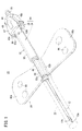
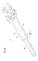
- FIG. 1 is an overall perspective view of a medical needle according to an embodiment of the present invention. It is a whole perspective view of a medical needle in a state where a needle body is accommodated in an accommodation cylinder. It is a disassembled perspective view of a medical needle. It is a perspective view which shows the accommodation cylinder of a medical needle. It is a perspective view which shows the locking member of a medical needle.
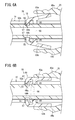
- FIG. 6A is a longitudinal sectional view showing an engaged state between the lock member and the shaft
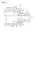
- FIG. 6B is a longitudinal sectional view showing a disengaged state between the lock member and the shaft. It is sectional drawing which shows the engagement structure of the shaft in a medical needle of the state shown in FIG. 2, and an accommodating cylinder, and its peripheral site
- FIG. 1 and 2 are overall perspective views showing a configuration of a medical needle 10 according to an embodiment of the present invention.
- the medical needle 10 is in a state where the needle body 12 protrudes from the housing cylinder 16 by a predetermined length, and in FIG. 2, the needle body 12 is housed in the housing cylinder 16.
- FIG. 3 is an exploded perspective view of the medical needle 10.
- the medical needle 10 is configured as a winged needle that is fixed and used while being punctured into the patient's skin during blood collection, blood transfusion, infusion, or the like.
- this invention is applicable not only to a winged needle but the other kind of medical needle 10, for example, the indwelling needle etc. which are used when performing continuous intravenous infusion.
- the medical needle 10 configured as a winged needle includes a needle body 12, a hub 14, a housing cylinder 16, a lock member 18, and a wing member 20.
- the needle body 12 is a portion that is punctured into the skin of a patient undergoing treatment such as blood sampling, blood transfusion, and fluid transfusion, and is made of, for example, a metal material such as stainless steel, aluminum or aluminum alloy, titanium or titanium alloy, and the like.
- a sharp needle tip 12a is formed at the tip.
- the needle body 12 is configured in a circular tube shape having a hollow portion serving as a flow path for body fluid such as blood or infusion.
- An opening 12 b that functions as a liquid inlet / outlet is formed at the tip of the needle body 12.
- the cap 22 Prior to use of the medical needle 10, the cap 22 is attached to the medical needle 10.
- the cap 22 is formed in a hollow cylindrical shape that can accommodate the needle body 12 therein, and is fitted to the distal end side of the wing member 20 on the proximal end side so that the medical needle is covered with the needle body 12. 10 can be mounted. When using the medical needle 10, the cap body 22 can be pulled away from the wing member 20 to expose the needle body 12.
- the hub 14 is connected to the proximal end of the needle body 12 and supports the needle body 12.
- the hub 14 is connected to the proximal end of the needle body 12 coaxially with the needle body 12, and a hollow shaft 24 whose hollow portion communicates with the lumen of the needle body 12, and the proximal end of the shaft 24.
- an operation unit 26 fixed in the vicinity.
- the proximal end of the needle body 12 is inserted and fixed at the distal end of the shaft 24.
- the shaft 24 is configured to have a larger diameter than the needle body 12.
- an annular protrusion 28 that bulges outward in the radial direction and extends over one circumference in the circumferential direction is provided at the tip of the shaft 24.
- the protrusion 28 is a portion that engages with the elastic engagement pieces 30, 30 provided on the housing cylinder 16 when the shaft 24 comes to a retracted position (a second position described later) with respect to the housing cylinder 16. It is.
- another shape of protrusion that protrudes in a direction orthogonal to the axis of the shaft 24 may be provided in a partial range of the shaft 24 in the circumferential direction.
- the protruding portion 28 or the protruding portion having another shape may be provided at a position slightly shifted to the proximal end side with respect to the distal end of the shaft 24 instead of the distal end of the shaft 24.
- Two engagement grooves 34 are provided on both left and right side portions of the shaft 24 in the longitudinal direction (in the illustrated example, near the center in the longitudinal direction).
- the engaging grooves 34 and 34 have a groove shape in which the outer peripheral portion of the shaft 24 is partially cut out in the circumferential direction, but instead of the engaging grooves 34 and 34 having such a configuration, the shaft An annular engagement groove that goes around the outer periphery of 24 may be provided.
- the left and right engaging grooves 34 are provided at the same position in the axial direction of the shaft 24, but may be provided at positions shifted from each other in the axial direction of the shaft 24.
- a tube connecting portion 36 that can be connected to a tube (not shown) connected to an infusion bag, a blood bag, or the like is provided.
- a flange portion 38 bulging in the radial direction is provided on the distal end side of the tube connecting portion 36.
- a reduced diameter portion 40 is provided between the guide groove 32 and the flange portion 38, which is narrower than its front and rear portions.
- the operation unit 26 is a part that the user picks with fingers and performs a pressing operation and a backward operation.
- the operation portion 26 includes a base portion 44 in which a notch-like fitting groove is formed to be fitted to the reduced diameter portion 40, and extends from the outer end (left and right ends) of the base portion 44 toward the distal end of the medical needle 10 and the shaft 24.
- a pair of operation arms 46a and 46b that can be elastically deformed in the radial direction (left and right direction in the illustrated example).
- Each of the operation arms 46a and 46b is a plate-like portion that extends away from the outer peripheral surface of the receiving cylinder 16 so as to face the outer peripheral surface. (The direction in which the pair of operation arms 46a and 46b approach each other) can be elastically displaced.
- Each of the operation arms 46a and 46b is provided with a groove for preventing slip on the outer surface side of the tip, and the inner surface in the vicinity of the tip is opposed to the release levers 63a and 63b of the lock member 18.
- the operation arms 46a and 46b are pressed inward (inward in the radial direction of the shaft 24).
- the pressing operation force required for the engagement release operation is related to the material, plate thickness, width, length, and the like of the operation arms 46a and 46b. Therefore, the material, plate thickness, width, length, etc. of the operation arms 46a, 46b are related with a small operation force when the operation arms 46a, 46b are pressed to release the engagement between the lock member 18 and the shaft 24. It is good to set so that you can cancel.
- the operation unit 26 further includes an upper plate 47 extending from the upper end of the base 44 toward the distal end of the medical needle 10.
- the upper plate 47 has a size (width and length) that covers a portion (a base end portion of the storage tube 16) between the two operation arms 46 a and 46 b of the storage tube 16, and the outer periphery of the storage tube 16. It faces away from the surface.
- An arrow-shaped mark 49 is provided on the upper surface of the operation unit 26 to indicate the operation direction of the operation unit 26 when the needle body 12 is stored in the storage cylinder 16.
- the constituent materials of the shaft 24 and the operation unit 26 are not particularly limited.
- examples thereof include butadiene-styrene copolymers, polyesters such as polyethylene terephthalate and polyethylene naphthalate, butadiene-styrene copolymers, polyamides (for example, nylon 6, nylon 6,6, nylon 6,10, nylon 12) and the like.
- the housing cylinder 16 includes a first pipe portion 48 that constitutes the distal end side of the housing cylinder 16, and a shaft 24 that is provided at the base end of the first pipe portion 48 and that has an axial direction inside. And a second pipe part 50 disposed so as to be displaceable.
- the housing cylinder 16 is configured to cover the needle tip 12 a of the needle body 12 when the shaft 24 is retracted to a predetermined position with respect to the housing cylinder 16. That is, the storage cylinder 16 functions as a protector that covers the needle tip 12 a of the needle body 12 after the use of the medical needle 10.
- the accommodating cylinder 16 is fitted and fixed inside the wing shaft 88 of the wing member 20 in a predetermined range near the tip (in the present embodiment, a portion of the first pipe portion 48).
- the housing cylinder 16 includes a first member 52 a and a second member 52 b that are divided into upper and lower parts, and includes a first member 52 a and a second member 52 b.
- a lumen 53 that penetrates in the axial direction and through which the needle body 12 can be inserted is formed.
- the lumen provided in the housing cylinder 16 includes a first lumen 53 a formed in the first tube portion 48 and a second lumen 53 b formed in the second tube portion 50. Become.
- the inner diameter of the second lumen 53b is larger than the inner diameter of the first lumen 53a.
- the first tube portion 48 is a relatively thin portion disposed inside the wing shaft portion 88.
- the second pipe part 50 is configured to be thicker (larger in diameter) than the first pipe part 48, and the shaft 24 is disposed inside the second pipe part 50 so as to be displaceable in the axial direction.
- the shaft 24 has a first position where the distal end of the needle body 12 protrudes from the housing cylinder 16 by a predetermined length with respect to the housing cylinder 16 and the distal end of the shaft 24 is disposed in the second pipe portion 50 (see FIG. 1). Then, the tip of the needle body 12 can be slid to the second position (see FIG. 2) where the tip of the needle body 12 is housed in the housing cylinder 16.
- First side holes 55 and 55 that communicate between the inside and the outside of the second pipe part 50 are provided on the left and right side parts of the second pipe part 50.
- the 1st side holes 55 and 55 are provided in the substantially exact opposite position in the storage cylinder 16 (2nd pipe part 50).
- the first side holes 55 and 55 are formed by notch-like recesses 82 and 82 (see also FIG. 3) provided in the first member 52a and notch-like recesses 83 and 83 (see FIG. 3) provided in the second member 52b. 3).
- a fixing portion 58 for positioning the lock member 18 in the axial direction is provided at an intermediate position in the axial direction of the second pipe portion 50.
- the fixing portion 58 is an arc-shaped groove 58a extending in the circumferential direction at the inner peripheral portion of the second member 52b, and the lock member 18 having a similar arc shape is connected to the arc-shaped groove 58a.
- a portion 66 is arranged.
- second side holes 85 and 85 that communicate between the inside and the outside of the housing cylinder 16 are provided at locations (left and right side portions) corresponding to both ends of the arc-shaped groove 58 a.
- the second side holes 85 and 85 are provided at substantially opposite positions in the housing cylinder 16 (second pipe portion 50).
- the second side holes 85 and 85 are formed by notched concave portions 86 and 86 provided in the first member 52a and notched concave portions 87 and 87 provided in the second member 52b.
- the lock member 18 is fixed to the housing cylinder 16 so as to be swingable at an intermediate position in the axial direction of the housing cylinder 16 and is disposed on the outer side of the housing cylinder 16.
- 63b, and engagement portions 64a and 64b that are provided on the release levers 63a and 63b and are releasably engaged with the shaft 24 via the first side holes 55 and 55.
- two release levers 63a and 63b and two engaging portions 64a and 64b are provided, and a connecting portion 66 that interconnects the two release levers 63a and 63b between the two release levers 63a and 63b. Is provided.
- the connecting portion 66 is fixed in the housing cylinder 16 and supports the two release levers 63 a and 63 b via second side holes 85 and 85 provided in the housing cylinder 16.
- the two release levers 63a and 63b, the two engaging portions 64a and 64b, and the connecting portion 66 are integrally molded to constitute a single lock member 18.
- the connecting portion 66 supports the release levers 63a and 63b on the inner surfaces of the release levers 63a and 63b (surfaces facing the housing cylinder 16) in the middle of the release levers 63a and 63b.
- the release levers 63a and 63b are swingable with the portion as a fulcrum.
- the engaging portions 64a and 64b have a shape bent inward at the ends of the release levers 63a and 63b, and the engaging grooves 34 and 34 of the shaft 24 at the first position are formed at the inner ends 65 and 65 thereof. Can be engaged.
- the engagement portions 64a and 64b are engaged after the engagement between the engagement portions 64a and 64b and the engagement grooves 34 and 34 is released (after the engagement portions 64a and 64b are displaced outward).
- Return prevention protrusions 67 and 67 for preventing the portions 64a and 64b from being displaced inward again and projecting from the inner peripheral surface of the housing cylinder 16 are provided.
- the return prevention protrusion 67 is provided on the front surface of the engaging portions 64a and 64b, but may be provided on the other surface of the engaging portions 64a and 64b as long as the above function can be achieved. . Further, in the present embodiment, the return prevention protrusions 67 and 67 are located inside the housing cylinder 16 (second lumen 53b) in a state where the engaging portions 64a and 64b are engaged with the engaging grooves 34 and 34, respectively. May be provided so as to be located in the first side holes 55, 55.
- the release levers 63a and 63b are moved by the operating arms 46a and 46b.
- the direction is changed (tilted) with both ends of the connecting portion 66 as fulcrums.
- the connecting portion 66 bends due to elastic deformation, the proximal ends of the release levers 63a and 63b are displaced inward with respect to both ends of the connection portion 66, and the distal ends of the release levers 63a and 63b are outward. Displace.
- the engagement portions 64a and 64b are disengaged from the engagement grooves 34 and 34, that is, the engagement between the engagement portions 64a and 64b and the engagement grooves 34 and 34 is released.
- the movement of the shaft 24 in the axial direction with respect to the housing cylinder 16 is allowed.
- the shaft 24 can be released to the first position with respect to the housing cylinder 16 by the engaging portions 64 a and 64 b of the lock member 18 and the engaging grooves 34 and 34 of the shaft 24.
- First locking means 39 (see FIG. 6A) to be locked is configured.
- the number of release levers 63a and 63b (and the engaging portions 64a and 64b) provided on the lock member 18 is not limited to two, and may be only one. In this case, the number of the first side holes 55 provided in the housing cylinder 16 and the engagement groove 34 provided in the shaft 24 are only one.
- elastic engagement pieces 30, 30 are provided in the vicinity of the base end portion of the housing cylinder 16 at positions facing each other. Specifically, one elastic engagement piece 30 is provided on the first member 52a, and the other elastic engagement piece 30 is provided on the second member 52b. In the present embodiment, an opening 33 is provided in the vicinity of the base end portions of the first member 52 a and the second member 52 b, and the elastic engagement pieces 30, 30 are formed from the side portion on the tip end side of the opening 33. Project in the end direction. Note that only one elastic engagement piece 30 may be provided.
- the elastic engagement pieces 30, 30 each have a tapered surface 84 that is inclined so as to approach the inside of the storage cylinder 16 toward the proximal direction inside the storage cylinder 16.
- the protrusion 28 provided on the shaft 24 presses the elastic engagement piece 30 outward.
- the elastic engagement piece 30 is elastically deformed outward (outward in the radial direction of the housing cylinder 16), so that the protrusion 28 gets over the elastic engagement piece 30.
- the shaft 24 opposes the elastic engagement pieces 30, 30 at the second position displaced to the most proximal side with respect to the housing cylinder 16. Between the wall portions 31, 31, the movement in the axial direction is prevented with respect to the housing cylinder 16.
- the second lock that causes the shaft 24 to be substantially unreleasably locked at the second position with respect to the housing cylinder 16 by the elastic engagement pieces 30 and 30, the wall portions 31 and 31, and the projection portion 28.
- Means 41 are configured.
- the constituent material of the housing cylinder 16 and the lock member 18 described above is not particularly limited, and for example, one or more materials selected from those exemplified as the constituent materials of the shaft 24 and the operation unit 26 described above may be employed. Further, if the lock member 18 is more easily deformed than the housing cylinder 16, that is, if it is made of a soft material (for example, polyacetal), the connecting portion 66 of the lock member 18 is easily elastically deformed with a small force. When the engagement between the member 18 and the shaft 24 is released, the pressing operation force on the operation arms 46a and 46b can be reduced, and the operability can be improved.
- a soft material for example, polyacetal
- the wing member 20 includes a hollow wing shaft portion 88 and a pair of wings 90 a and 90 b projecting left and right from the wing shaft portion 88.
- the wings 90a and 90b are formed in a plate shape that is coupled to the wing shaft portion 88 at the root portion and becomes wider from the root portion toward the outer end.
- the wings 90a and 90b have flexibility, and are configured to be openable and closable by bending or bending near the root.
- Thin portions 92a and 92b are formed in the vicinity of the base portions of the wings 90a and 90b so as to facilitate opening and closing.
- the upper surface of one wing 90a is provided with a plurality (two in the illustrated example) of convex portions 94
- the upper surface of the other wing 90b is provided with a plurality of (two in the illustrated example) concave portions as the convex portions 94.
- 96 is provided, and when the pair of wings 90a and 90b are closed (folded), the convex portion 94 and the concave portion 96 are fitted.
- One convex portion 94 and one concave portion 96 may be provided.
- the wing shaft portion 88 and the wings 90a and 90b in the illustrated example are integrally formed. However, the wing shaft portion 88 and the wings 90a and 90b are formed separately and combined to form the wing member 20. Good. Although it does not specifically limit as a constituent material of the wing axial part 88 and wings 90a and 90b, For example, the 1 or more types of material selected from what was illustrated as constituent materials, such as the accommodating part mentioned above, can be employ
- the wing shaft portion 88 is made of a material having high rigidity so as not to bend during use, and the wings 90a and 90b are flexible so that the root portion can be bent and can be easily opened and closed. You may comprise with material.
- the wing member 20 in which the wing shaft portion 88 and the wings 90a and 90b are integrally formed can be manufactured, for example, by two-color molding using a resin material having a relatively high rigidity and a resin material having a relatively low rigidity.
- the medical needle 10 according to the present embodiment is basically configured as described above, and the operation and effect will be described below.
- the cap 22 is removed from the medical needle 10 to expose the needle body 12.
- the pair of wings 90a and 90b are picked with fingers and closed (folded). Specifically, the bases of both wings 90a, 90b are bent and closed so that one wing 90a and the other wing 90b overlap.
- the convex part 94 provided in one wing 90a and the concave part 96 provided in the other wing 90b are fitted to each other, thereby preventing mutual displacement.
- the needle body 12 When the wings 90a and 90b are in the closed state, the needle body 12 is punctured into the living body while holding the closed wings 90a and 90b with fingers. At this time, as shown in FIG. 6A, the engaging portions 64 a and 64 b of the lock member 18 are engaged with the engaging grooves 34 and 34 provided in the shaft 24. The movement in the axial direction is blocked. That is, the needle body 12 is prevented from moving backward with respect to the housing cylinder 16 and the wing member 20 fixed thereto. For this reason, the needle body 12 does not move backward with respect to the housing cylinder 16 due to the puncture resistance when the wing member 20 is picked with a finger and the needle body 12 is punctured into the living body.
- the wings 90a and 90b are returned to the opened state, and the wings 90a and 90b are fixed to the skin with an adhesive tape or the like.
- the engagement between the engagement portions 64a and 64b and the engagement grooves 34 and 34 is released, and the shaft 24 is movable in the proximal direction with respect to the storage cylinder 16.
- the two operation arms 46a and 46b of the operation unit 26 are pressed inward (side of the housing cylinder 16).
- the release levers 63a and 63b of the lock member 18 facing the inside of the operation arms 46a and 46b are pressed inward by the operation arms 46a and 46b, thereby supporting the release levers 63a and 63b.
- the release levers 63a and 63b (specifically, the portion on the base end side relative to the fulcrum of the release levers 63a and 63b) are displaced inward, The engaging portions 64a and 64b are displaced outward. As a result, as shown in FIG. 6B, the engagement between the engagement portions 64a and 64b and the engagement grooves 34 and 34 is released.
- the engagement portions 64a and 64b are provided with the return prevention protrusions 67.
- the operation unit 26 is pulled in the proximal direction with respect to the housing cylinder 16 in a state where the engagement between the engagement portions 64a and 64b and the engagement grooves 34 and 34 is released. Then, the needle body 12 fixed to the distal end of the hub 14 is displaced in the proximal direction with respect to the housing cylinder 16. Even when the operating arms 46a and 46b are not pressed inward, the engagement between the engaging portions 64a and 64b and the engaging grooves 34 and 34 is maintained by the action of the return preventing projection 67. The Therefore, the user can displace the operation unit 26 in the proximal direction without pressing the operation arms 46a and 46b inward.
- the engaging portions 64 a and 64 b do not contact the outer peripheral surface of the shaft 24 while the operation portion 26 is displaced in the proximal direction, frictional resistance due to contact between the engaging portions 64 a and 64 b and the shaft 24 may occur. Therefore, the operation of moving the operation unit 26 in the proximal direction can be performed smoothly.
- the needle body 12 In the state where the hub 14 is moved to the most proximal side with respect to the housing cylinder 16, the needle body 12 is located inside the housing cylinder 16 (specifically, inside the first pipe portion 48). As shown in FIG. 2, when the shaft 24 moves to a predetermined retracted position (second position), the action of the second locking means 41 (see FIG. 7) described above causes the shaft 24 to move forward relative to the housing cylinder 16. Movement is prevented. Therefore, the needle body 12 does not protrude from the tip of the housing cylinder 16 again. Further, since the second locking means 41 prevents the backward movement of the shaft 24 with respect to the housing cylinder 16, the needle body 12 is effectively prevented from being pulled out from the proximal end of the housing cylinder 16.
- the distal end of the shaft 24 when the shaft 24 comes to the most distal side of the movable range is more proximal than the first tube portion 48 of the housing cylinder 16. Since it is in the 2nd pipe part 50 of the side, the 1st pipe part 48 of the accommodation cylinder 16 is easy to comprise. That is, since the shaft 24 is not inserted into the first tube portion 48 that constitutes the distal end side of the housing cylinder 16, the outer diameter of the first tube portion 48 can be set to be reduced accordingly. For this reason, the trunk
- the shaft 24 is adopted by adopting a configuration in which the lock member 18 is disposed not on the proximal end of the housing cylinder 16 but on the distal end side (an intermediate portion in the axial direction of the housing cylinder 16).
- the distal end of the medical needle 10 is arranged at a position shifted to the proximal end side as compared with the prior art, it is possible to prevent the entire length of the medical needle 10 from being increased.
- the medical needle 10 according to the present invention the operability can be improved by thinning the trunk without increasing the overall length.
- the lock member 18 has two release levers 63a and 63b on opposite sides with respect to the shaft 24, so that the engaging portions 64a and 64b are engaged so as to be held from both sides of the shaft 24. Therefore, a high engagement force can be obtained, and the engagement state between the engagement portions 64a and 64b and the shaft 24 can be reliably maintained unless the engagement release portion is pressed inward.
- the connecting portion 66 that interconnects the two release levers 63 a and 63 b is fixed in the housing cylinder 16 and via the second side holes 85 and 85 provided in the housing cylinder 16. Two release levers 63a and 63b are supported. With this configuration, since the connecting portion 66 fixed to the storage cylinder 16 supports the two release levers 63a and 63b, the lock member 18 can be firmly fixed to the storage cylinder 16 and the two release levers 63a and 63b.
- the lock member 18 including can be configured compactly as a single part.
- the lock member 18 is made of a material that is more easily deformed than the housing cylinder 16, so that the operation force required for the disengagement operation between the lock member 18 and the shaft 24 can be reduced. Can be improved.
- the housing cylinder 16 is composed of a first member 52a and a second member 52b that are divided into upper and lower parts, and the connecting portion 66 of the lock member 18 is the inner periphery of the second member 52b. It has a shape that is bent or curved along the portion, and is disposed in the fixed portion 58 that is formed by the arc-shaped groove 58a provided in the second member 52b. According to this configuration, the body part of the medical needle 10 can be assembled by sequentially stacking the first member 52a, the lock member 18, the shaft 24, and the second member 52b. Contributes to improved productivity.
- fixed part 58 of the locking member 18 was provided in the 1st member 52a
- fixed part 58 of the locking member 18 may be provided in the 2nd member 52b side as a modification.
- the lock member 18 is disposed upside down from the direction shown in FIG.
- the lock member 18 may be arranged in the reverse direction from the direction shown in FIG.
- both of the pressing operation for releasing the engagement between the lock member 18 and the shaft 24 and the pulling operation for moving the shaft 24 in the proximal direction with respect to the housing cylinder 16 are performed on the operation unit 26. Therefore, it is excellent in operability.
- the operation arms 46a and 46b are configured in a plate shape, the pressure required for releasing the engagement between the lock member 18 and the shaft 24 by setting the operation arms 46a and 46b to be appropriately long. The operating force can be easily reduced.
- the medical needle 10 is configured as a winged needle having a wing shaft portion 88 and a pair of wings 90a and 90b.
- the wing shaft portion 88 surrounding the first tube portion 48 can also be made thin.
- the needle tip 12a of the needle body 12 is likely to be stabilized during the operation of picking the wing shaft portion 88 over the root portions of the folded wings 90a and 90b and puncturing the needle body 12 into the living body. Therefore, a winged needle excellent in operability can be provided.
Landscapes
- Health & Medical Sciences (AREA)
- Vascular Medicine (AREA)
- Engineering & Computer Science (AREA)
- Anesthesiology (AREA)
- Biomedical Technology (AREA)
- Heart & Thoracic Surgery (AREA)
- Hematology (AREA)
- Life Sciences & Earth Sciences (AREA)
- Animal Behavior & Ethology (AREA)
- General Health & Medical Sciences (AREA)
- Public Health (AREA)
- Veterinary Medicine (AREA)
- Infusion, Injection, And Reservoir Apparatuses (AREA)
Description
本発明は、採血、輸血、輸液等に用いられる医療用針に関する。
採血、輸血、輸液等において、血液バッグ、血液処理回路(成分採血回路、血液透析回路等)の採血器具、輸血セット、輸液セット等に接続して使用する医療用針が知られている。このような医療用針は、一般に、先端に鋭利な針先を有する針体と、この針体の基端に設けられたハブとから構成される。使用後の医療用針を廃棄する場合には、廃棄作業者が不用意に針体に触れることを防止するために、針体を覆う必要がある。そのため、従来では、使用後の針体を覆うことができるプロテクタを備えた医療用針が提案されている(例えば、特許第3134920号公報参照)。
特許第3134920号公報に開示された翼付留置針(医療用針)は、カヌラ(針体)と、カヌラの基端に設けられたハブと、ハブを内部に収容して保持する保持筒(プロテクタ)とを備え、ハブに支持されたカヌラの先端が保持筒先端から突出する第1の位置から保持筒内に収容される第2の位置まで保持筒の内壁に沿ってスライド可能であり、ハブと保持筒の間に、ハブを保持筒の第1の位置に解除可能に係止させる第1係合手段と、ハブを保持筒の第2の位置に実質的に解除不能に係止させる第2係合手段が設けられている。
ところで、医療用針の使用においては、医療用針の胴体部(特許第3134920号公報では、保持筒)を指で摘み、針体を患者の皮膚に穿刺する。この場合、医療用針の胴体部が適度に細径であると、使用者が胴体部を摘み易いことから針先を安定させ易く、硬い血管や細い血管を正確に穿刺し易い。
しかしながら、上述した特許第3134920号公報に開示された翼付留置針は、使用時の状態で、ハブの先端が保持筒の先端の位置まで挿入される構造であるため、胴体部である保持筒を細く構成することが困難である。
本発明はこのような課題を考慮してなされたものであり、胴体部を細くすることにより操作性を向上させることができる医療用針を提供することを目的とする。
本発明はこのような課題を考慮してなされたものであり、胴体部を細くすることにより操作性を向上させることができる医療用針を提供することを目的とする。
上記の目的を達成するため、本発明に係る医療用針は、先端に針先を有する針体と、前記針体の基端に設けられたシャフトと、第1管部と、前記第1管部の基端に設けられ且つ内側に前記シャフトが軸線方向に変位可能に配置された第2管部とを有し、前記第2管部に第1の側孔が設けられた収容筒と、前記収容筒の軸線方向の途中部位に前記収容筒に揺動可能に固定されるとともに前記収容筒の外側に配置された解除レバーと、前記解除レバーに設けられ前記第1の側孔を介して前記シャフトに対して解除可能に係合する係合部とを有するロック部材と、を備え、前記シャフトは、前記収容筒に対して、前記針体の先端が前記収容筒から所定長突出し且つ当該シャフトの先端が前記第2管部内に配置される第1の位置から、前記針体の先端が前記収容筒内に収容される第2の位置までスライド可能であり、前記係合部が前記シャフトに係合することにより、前記シャフトが前記収容筒に対して前記第1の位置に係止され、前記解除レバーが内方に押圧されることに伴い前記係合部が外方に変位することにより、前記係合部と前記シャフトとの係合が解除されることを特徴とする。
上記の構成によれば、シャフトが可動範囲の最も先端側に来たときのシャフトの先端が、収容筒の第1管部よりも基端側の第2管部内にあるため、収容筒の第1管部を細く構成し易い。すなわち、収容筒の先端側を構成する第1管部には、シャフトが挿通されないため、その分、第1管部の外径を小さく設定することが可能である。このため、医療用針の胴体部を容易に細径化することができる。細径化した胴体部は、使用者が手指により摘み易いため、操作性に優れた医療用針を提供することができる。また、本発明では、ロック部材を、収容筒の基端ではなく、当該基端よりも先端側(収容筒の軸線方向の途中部位)に配置する構成を採用することにより、シャフトの先端が従来技術と比較して基端側にずれた位置に配置される構成であるにもかかわらず、医療用針の全長が長くなることが抑制される。このように、本発明に係る医療用針によれば、全長を長大化することなく、胴体部を細くすることにより操作性を向上させることができる。
上記の医療用針において、前記ロック部材は、前記シャフトを基準として互いに反対側に前記解除レバーを2つ有してもよい。
上記の医療用針において、前記ロック部材は、前記シャフトを基準として互いに反対側に前記解除レバーを2つ有してもよい。
上記の構成によれば、シャフトの両側から抱え込むように係合部が係合するので、高い係合力が得られ、係合解除部が内方に押圧されない限り、係合部とシャフトとの係合状態を確実に保持することができる。
上記の医療用針において、前記ロック部材は、前記2つの解除レバーを相互連結する連結部をさらに備え、前記連結部は、前記収容筒内に固定されるとともに、前記収容筒に設けられた第2の側孔を介して前記2つの解除レバーを支持してもよい。
上記の構成によれば、収容筒に固定される連結部が2つの解除レバーを支持するので、ロック部材を収容筒に対して強固に固定できるとともに、2つの解除レバーを含むロック部材を単一の部品として構成することができる。
上記の医療用針において、前記ロック部材は、前記収容筒よりも変形し易い材料で構成されてもよい。
上記の構成によれば、ロック部材とシャフトとの係合解除操作に要する操作力を小さくすることができ、操作性を向上することができる。
上記の医療用針において、前記ロック部材は、前記連結部の弾性変形を伴って前記2つの解除レバーが変位してもよい。
上記の構成によれば、解除レバーに対して外力が付加されない状態ではロック部材とシャフトとの係合状態を安定的に維持できるとともに、解除レバーが内方に押圧された際には連結部が弾性変形することで解除レバーを確実に変位させることができる。
上記の医療用針において、前記収容筒は、上下に分割された半割れ状の第1部材と第2部材とから構成され、前記連結部は、前記第1部材と前記第2部材のうち一方に設けられた固定部に嵌合し、且つ前記第1部材と前記第2部材のうち前記固定部が設けられた側の内周部に沿って屈曲又は湾曲した形状を有してもよい。
上記の構成によれば、シャフト、ロック部材、第1部材及び第2部材を上下方向に重ねることで、医療用針の胴体部を組み立てることができるため、組立作業性に優れ、生産性の向上に寄与する。
上記の医療用針において、前記収容筒又は前記ロック部材には、前記係合部と前記シャフトとの係合が解除された後に前記係合部が前記収容筒の内周面から突出することを防止するための戻り防止突起が設けられてもよい。
上記の構成によれば、ロック部材とシャフトとの係合が解除された後は、ロック部材に対する押圧を解除してもロック部材とシャフトとが再び係合することがない。従って、係合解除操作が一層簡便となる。
上記の医療用針において、前記シャフトの基端には、使用者による操作がなされる操作部が設けられ、前記操作部は、先端方向に延出し且つ前記収容筒に対向して延在する弾性変形可能な板状の操作アームを備え、前記操作アームは、前記収容筒側に押圧操作された際、前記解除レバーを内方に押圧してもよい。
上記の構成によれば、ロック部材とシャフトとの係合を解除する押圧操作と、収容筒に対してシャフトを基端方向に移動させる引っ張り操作とを、いずれも操作部に対する操作として連続的に行うことができるため、操作性に優れる。また、操作アームが板状に構成されることから、これを適度に長く設定することにより、ロック部材とシャフトとの係合を解除する際に必要な押圧操作力を容易に低減することができる。
上記の医療用針において、前記医療用針は、前記第1管部を囲むウイング軸部と、前記ウイング軸部から互いに反対方向に突出した一対のウイングと、を有する翼状針として構成されてもよい。
上記の構成によれば、第1管部を細くできることから、第1管部を囲むウイング軸部も細く構成することが可能である。ウイング軸部が細いと、折り畳んだウイングの根元部を介してウイング軸部を摘み、針体を生体に穿刺する操作時に、針体の針先が安定し易い。従って、操作性に優れた医療用針を提供することができる。
本発明の医療用針によれば、胴体部を細くすることにより操作性を向上させることができる。
以下、本発明に係る医療用針について好適な実施形態を挙げ、添付の図面を参照しながら説明する。
図1及び図2は、本発明の一実施形態に係る医療用針10の構成を示す全体斜視図である。医療用針10は、図1では針体12が収容筒16から所定長突出した状態であり、図2では針体12が収容筒16内に収容された状態である。図3は、当該医療用針10の分解斜視図である。
本実施形態において、医療用針10は、採血、輸血、輸液等に際し、患者の皮膚に穿刺した状態で固定して使用される翼状針として構成されている。なお、本発明は、翼状針に限らず、他の種類の医療用針10、例えば、持続的な点滴静注を行う際に用いられる留置針等にも適用可能である。
翼状針として構成された医療用針10は、針体12と、ハブ14と、収容筒16と、ロック部材18と、翼部材20とを備える。
翼状針として構成された医療用針10は、針体12と、ハブ14と、収容筒16と、ロック部材18と、翼部材20とを備える。
針体12は、採血、輸血、輸液等の処置を受ける患者の皮膚に穿刺される部分であり、例えば、ステンレス鋼、アルミニウム又はアルミニウム合金、チタン又はチタン合金のような金属材料で構成され、その先端部には、鋭利な針先12aが形成されている。この針体12は、血液等の体液或いは輸液等の流路となる中空部を有する円管状に構成されている。針体12の先端部には、液体の出入口として機能する開口12bが形成されている。
医療用針10の使用前において、医療用針10にはキャップ22が装着されている。このキャップ22は、その内部に針体12を収納可能な中空筒状に構成され、基端側において翼部材20の先端側と嵌合することで、針体12を覆った状態で医療用針10に装着可能に構成されている。医療用針10を使用する際は、キャップ22を先端方向に引っ張ることで、翼部材20から離脱し、針体12を露出させることができる。
ハブ14は、針体12の基端に連結され、針体12を支持するものである。本実施形態において、ハブ14は、針体12の基端に針体12と同軸状に接続されその中空部が針体12の内腔と連通する中空状のシャフト24と、シャフト24の基端近傍に固定された操作部26とを備える。針体12の基端は、シャフト24の先端に挿入され固定されている。シャフト24は、針体12よりも大径に構成される。
図3に示すように、シャフト24の先端部には、半径方向外方に膨出し且つ周方向に一周に渡って延在する環状の突起部28が設けられている。当該突起部28は、シャフト24が収容筒16に対して後退位置(後述する第2の位置)に来たときに、収容筒16に設けられた弾性係合片30、30に係合する部分である。なお、環状の突起部28に代えて、シャフト24の周方向の一部の範囲で、シャフト24の軸線に対して直交する方向に突出する別形状の突起部が設けられてもよい。また、突起部28又は別形状の突起部は、シャフト24の先端ではなく、シャフト24の先端に対してやや基端側にずれた位置に設けられてもよい。
シャフト24の長手方向の途中部位(図示例では、長手方向の中央付近)の左右両側部には、2つの係合溝34、34が設けられている。本実施形態において、係合溝34、34は、シャフト24の外周部を周方向に部分的に切り欠いた溝形状を有するが、このような構成の係合溝34、34に代えて、シャフト24の外周を一周する環状の係合溝が設けられてもよい。また、本実施形態において、左右の係合溝34、34は、シャフト24の軸線方向に関して同じ位置に設けられているが、シャフト24の軸線方向に互いにずれた位置に設けられてもよい。
シャフト24の基端には、輸液バッグ、血液バッグ等に連結された図示しないチューブと接続可能なチューブ接続部36が設けられている。シャフト24の基端近傍でチューブ接続部36よりも先端側には、径方向に膨出したフランジ部38が設けられている。シャフト24における、ガイド溝32とフランジ部38との間には、その前後部分よりも細い縮径部40が設けられている。この縮径部40に操作部26が嵌合することで、シャフト24と操作部26とが相互に固定される。
操作部26は、使用者が手指で摘んで押圧操作及び後退操作する部分である。操作部26は、縮径部40に嵌合する切欠状の嵌合溝が形成された基部44と、基部44の外端(左右両端)から医療用針10の先端方向に延出し且つシャフト24の径方向(図示例では、左右方向)に弾性変形可能な一対の操作アーム46a、46bとを有する。操作アーム46a、46bは、それぞれ、収容筒16の外周面から離間した状態で、当該外周面に対向するように延在した板状部分であり、指で摘んで外側から押圧することにより、内方(一対の操作アーム46a、46bが互いに近づく方向)に弾性的に変位可能である。
操作アーム46a、46bの各々は、その先端外面側に滑り止め用の溝が設けられ、その先端近傍の内面がロック部材18の解除レバー63a、63bに対向している。ロック部材18とシャフト24との係合を解除する操作(係合解除操作)において、操作アーム46a、46bは内方(シャフト24の半径方向内方)に押圧操作される。係合解除操作時に必要な押圧操作力は、操作アーム46a、46bの材質、板厚、幅、長さ等に関係する。そのため、操作アーム46a、46bの材質、板厚、幅、長さ等は、操作アーム46a、46bを押圧してロック部材18とシャフト24との係合を解除する際に、小さい操作力で係合解除できるように設定されるとよい。
操作部26は、さらに、基部44の上端から医療用針10の先端方向に延出する上部プレート47を有する。上部プレート47は、収容筒16のうち2つの操作アーム46a、46bの間にある部分(収容筒16の基端部)を覆う大きさ(幅及び長さ)を有し、収容筒16の外周面から離間して対向している。なお、操作部26の上面には、針体12を収容筒16内に収納する際の操作部26の操作方向を示す矢印形状のマーク49が設けられている。
シャフト24及び操作部26の構成材料としては、特に限定されないが、例えば、ポリ塩化ビニル、ポリエチレン、ポリプロピレン、環状ポリオレフィン、ポリスチレン、ポリ-(4-メチルペンテン-1)、ポリカーボネート、アクリル樹脂、アクリロニトリル-ブタジエン-スチレン共重合体、ポリエチレンテレフタレート、ポリエチレンナフタレート等のポリエステル、ブタジエン-スチレン共重合体、ポリアミド(例えば、ナイロン6、ナイロン6・6、ナイロン6・10、ナイロン12)等が挙げられる。
図1及び図2に示すように、収容筒16は、収容筒16の先端側を構成する第1管部48と、第1管部48の基端に設けられ且つ内側にシャフト24が軸線方向に変位可能に配置された第2管部50とを有する。収容筒16は、シャフト24を収容筒16に対して所定位置まで後退させた際、針体12の針先12aを覆うように構成されている。すなわち、収容筒16は、医療用針10の使用後に、針体12の針先12aを覆うプロテクタとして機能する。
収容筒16は、先端寄りの所定範囲(本実施形態では、第1管部48の部分)において、翼部材20のウイング軸部88の内側に嵌合され固定されている。図3に示すように、本実施形態において、収容筒16は、上下に分割された半割れ状の第1部材52aと第2部材52bとから構成され、第1部材52aと第2部材52bとが結合することにより、その内部に、軸線方向に貫通し針体12が挿通可能な内腔53が形成される。図4に示すように、収容筒16に設けられた内腔は、第1管部48に形成された第1内腔53aと、第2管部50に形成された第2内腔53bとからなる。第2内腔53bの内径は、第1内腔53aの内径よりも大きい。
第1管部48は、ウイング軸部88の内側に配置される比較的細い部分である。第2管部50には、第1管部48よりも太く(大径に)構成され、その内側にシャフト24が軸線方向に変位可能に配置される。シャフト24は、収容筒16に対して、針体12の先端が収容筒16から所定長突出し且つ当該シャフト24の先端が第2管部50内に配置される第1の位置(図1参照)から、針体12の先端が収容筒16内に収容される第2の位置(図2参照)までスライド可能である。
第2管部50の左右両側部には、第2管部50の内外を連通する第1の側孔55、55が設けられる。本実施形態において、第1の側孔55、55は、収容筒16(第2管部50)において略正反対位置に設けられる。第1の側孔55、55は、第1部材52aに設けられた切欠状の凹部82、82(図3も参照)と、第2部材52bに設けられた切欠状の凹部83、83(図3も参照)とによって形成される。
第2管部50の軸線方向の途中部位には、ロック部材18を軸線方向に位置決めするための固定部58が設けられる。本実施形態において、固定部58は、第2部材52bの内周部において周方向に延在する円弧状溝58aであり、当該円弧状溝58aに、同様の円弧形状を有するロック部材18の連結部66が配置される。収容筒16において、円弧状溝58aの両端部に相当する箇所(左右側部)には、収容筒16の内外を連通する第2の側孔85、85が設けられる。
第2の側孔85、85は、収容筒16(第2管部50)において略正反対位置に設けられる。第2の側孔85、85は、第1部材52aに設けられた切欠状の凹部86、86と、第2部材52bに設けられた切欠状の凹部87、87とによって形成される。
図2及び図5に示すように、ロック部材18は、収容筒16の軸線方向の途中部位に収容筒16に揺動可能に固定されるとともに収容筒16の外側に配置された解除レバー63a、63bと、解除レバー63a、63bに設けられ第1の側孔55、55を介してシャフト24に対して解除可能に係合する係合部64a、64bとを備える。本実施形態において、解除レバー63a、63bと係合部64a、64bは2つずつ設けられ、2つの解除レバー63a、63bの間には当該2つの解除レバー63a、63bを相互連結する連結部66が設けられる。連結部66は、収容筒16内に固定されるとともに、収容筒16に設けられた第2の側孔85、85を介して2つの解除レバー63a、63bを支持する。2つの解除レバー63a、63b、2つの係合部64a、64b及び連結部66は、これらが一体成型されて単一のロック部材18を構成する。
連結部66は解除レバー63a、63bの長手方向の途中部位において、解除レバー63a、63bの内面(収容筒16に対向する面)で解除レバー63a、63bを支持しており、連結部66の両端部を支点として、解除レバー63a、63bが揺動可能である。シャフト24が収容筒16に対して第1の位置(図1参照)にあるとき、操作部26の操作アーム46a、46bは、解除レバー63a、63bに対向する位置にあり、この位置で操作アーム46a、46bを内方(収容筒16に近づく方向)に押圧すると、解除レバー63a、63bが操作アーム46a、46bによって押圧されることで、解除レバー63a、63bの基端部が内方に変位させられる。
係合部64a、64bは、解除レバー63a、63bの先端で内方に屈曲した形状を有し、その内方端65、65で、第1の位置にあるシャフト24の係合溝34、34に係合可能である。係合部64a、64bには、係合部64a、64bと係合溝34、34との係合を解除した後(係合部64a、64bを外方に変位させた後)に、係合部64a、64bが再び内方に変位して収容筒16の内周面から突出することを防止するための戻り防止突起67、67が設けられる。本実施形態では、戻り防止突起67は、係合部64a、64bの前面に設けられているが、上記の機能を達成できる限りで係合部64a、64bの他の面に設けられてもよい。また、本実施形態では、戻り防止突起67、67は、係合部64a、64bが係合溝34、34に係合した状態で、収容筒16の内部(第2内腔53b)に位置するが、第1の側孔55、55内に位置するように設けられてもよい。
シャフト24が収容筒16に対して第1の位置にあり且つ操作アーム46a、46bが自然状態(操作アーム46a、46bに対して押圧操作していない状態)のとき、図6Aに示すように、係合部64a、64bは、第1の側孔55、55を介してシャフト24に設けられた係合溝34、34に係合する。係合部64a、64bとシャフト24の係合溝34、34とが係合した状態では、シャフト24の収容筒16に対する軸線方向の移動が阻止される。
図6Bに示すように、シャフト24が収容筒16に対して第1の位置にある状態で、操作アーム46a、46bを内方に押圧操作すると、操作アーム46a、46bによって解除レバー63a、63bが内方に押圧されることで、連結部66の両端を支点として、向きを変える(傾動する)。具体的には、連結部66が弾性変形によって撓むとともに、連結部66の両端を基準に、解除レバー63a、63bの基端側が内方に変位し、解除レバー63a、63bの先端側が外方に変位する。この結果、係合部64a、64bが係合溝34、34から離脱した状態、すなわち、係合部64a、64bと係合溝34、34との係合が解除されるに至る。係合部64a、64bと係合溝34、34との係合が解除された状態では、シャフト24の収容筒16に対する軸線方向の移動が許容される。
このように、本実施形態では、ロック部材18の係合部64a、64bと、シャフト24の係合溝34、34とにより、シャフト24を収容筒16に対して第1の位置に解除可能に係止させる第1ロック手段39(図6A参照)が構成される。
なお、ロック部材18に設けられる解除レバー63a、63b(及び係合部64a、64b)は2つに限らず、1だけでもよい。この場合、収容筒16に設けられる第1の側孔55及びシャフト24に設けられる係合溝34は、それぞれ1つだけでよい。
図3及び図4に示すように、収容筒16の基端部近傍には、互いに対向する位置に、弾性係合片30、30が設けられる。具体的には、一方の弾性係合片30は第1部材52aに設けられ、他方の弾性係合片30は第2部材52bに設けられる。本実施形態において、第1部材52aと第2部材52bの基端部近傍には、開口部33が設けられ、弾性係合片30、30は、当該開口部33の先端側の辺部から基端方向に突出する。なお、弾性係合片30は、1つだけ設けられてもよい。
図7に示すように、収容筒16の内側において、弾性係合片30、30は、それぞれ、基端方向に向かって収容筒16の内方に寄るように傾斜したテーパ面84を有する。収容筒16に対してシャフト24が第1の位置から第2の位置に向かって移動する際、シャフト24に設けられた突起部28が、弾性係合片30を外方に押圧することにより、弾性係合片30が外方(収容筒16の径方向外方)に弾性変形し、これにより突起部28が弾性係合片30を乗り越える。
シャフト24は、収容筒16に対して最も基端側に変位した第2の位置において、図7に示すように、弾性係合片30、30と、当該弾性係合片30、30に対向する壁部31、31との間で、収容筒16に対して軸線方向の移動が阻止される。本実施形態では、弾性係合片30、30、壁部31、31及び突起部28により、シャフト24を収容筒16に対して第2の位置に実質的に解除不能に係止させる第2ロック手段41が構成される。
上述した収容筒16とロック部材18の構成材料としては、特に限定されず、例えば、上述したシャフト24及び操作部26の構成材料として例示したものから選択した一種以上の材料を採用し得る。また、ロック部材18は、収容筒16よりも変形し易い、すなわち軟質の材料(例えば、ポリアセタール等)で構成されると、ロック部材18の連結部66が小さい力で弾性変形し易いため、ロック部材18とシャフト24との係合を解除する際の、操作アーム46a、46bに対する押圧操作力を低減でき、操作性を向上できる。
図1に示すように、翼部材20は、中空状のウイング軸部88と、このウイング軸部88から左右にそれぞれ突出する一対のウイング90a、90bとを有する。ウイング90a、90bは、根元部においてウイング軸部88と結合し、根元部から外端に向かって幅広になる板状に形成されている。ウイング90a、90bは、可撓性を有し、根元部付近が屈曲又は湾曲することにより、開閉可能に構成されている。ウイング90a、90bの根元部付近には、開閉を容易にするため、ウイング軸部88の軸線方向に沿った薄肉部92a、92bが形成されている。
一方のウイング90aの上面には、複数(図示例では2つ)の凸部94が設けられ、他方のウイング90bの上面には、凸部94と同数の複数(図示例で2つ)の凹部96が設けられており、一対のウイング90a、90bが閉じられた(畳まれた)際に、凸部94と凹部96とが嵌合するようになっている。凸部94と凹部96は、それぞれ1つずつ設けられてもよい。
図示例のウイング軸部88とウイング90a、90bとは、一体的に形成されているが、ウイング軸部88とウイング90a、90bとを別々に形成し、それらを結合して翼部材20としてもよい。ウイング軸部88とウイング90a、90bの構成材料としては、特に限定されないが、例えば、上述した収容部等の構成材料として例示したものから選択した一種以上の材料を採用し得る。
ウイング軸部88は、使用時に撓まないように剛性の高い材料で構成し、ウイング90a、90bは、根元部が屈曲して容易に開閉可能な適度の可撓性を有すように柔軟な材料で構成してもよい。ウイング軸部88とウイング90a、90bとが一体的に形成された翼部材20は、例えば、比較的剛性の高い樹脂材料と、比較的剛性の低い樹脂材料を用いた二色成型により製作できる。
本実施形態に係る医療用針10は、基本的には以上のように構成されるものであり、以下、その作用及び効果について説明する。
上記のように構成された医療用針10を用いて採血、輸血、輸液等を行うには、先ず、医療用針10からキャップ22を取り外し、針体12を露出させる。次に、一対のウイング90a、90bを指で摘んで閉じた(畳んだ)状態とする。具体的には、両ウイング90a、90bの根元部を屈曲させて一方のウイング90aと他方のウイング90bを重ね合わせるようにして閉じる。このとき、一方のウイング90aに設けられた凸部94と他方のウイング90bに設けられた凹部96とが嵌合し、互いのずれが防止される。
ウイング90a、90bを閉じた状態としたら、次に、閉じられたウイング90a、90bを指で摘んで保持しつつ、針体12を生体に対して穿刺する。このとき、図6Aに示すように、ロック部材18の係合部64a、64bと、シャフト24に設けられた係合溝34、34とが係合しているため、収容筒16に対するシャフト24の軸線方向の移動が阻止された状態となっている。すなわち、収容筒16及びこれに固定された翼部材20に対して針体12が後退することが阻止された状態となっている。このため、翼部材20を指で摘んで針体12を生体に対して穿刺する際の穿刺抵抗で針体12が収容筒16に対して後退することがない。
針体12を生体に対して穿刺した状態で留置する際には、ウイング90a、90bを開いた状態に戻し、ウイング90a、90bを粘着テープ等により皮膚に固定する。
採血、輸血、輸液等が終了したら、粘着テープ等による皮膚に対するウイング90a、90bの固定を解除し、針体12を生体から抜き取る。このようにして、医療用針10の使用が終わったら、当該医療用針10を廃棄する者等の医療従事者が針体12に不用意に触れることを防止するために、プロテクタとして機能する収容筒16により針体12を覆って収納する「収納操作」を行う。
この収納操作では、第1ステップとして、係合部64a、64bと係合溝34、34部との係合を解除し、シャフト24が収容筒16に対して基端方向に移動可能な状態とする。具体的には、操作部26の2つの操作アーム46a、46bを内方(収容筒16側)に押圧する。操作アーム46a、46bを内方に押圧操作すると、その内側に対向するロック部材18の解除レバー63a、63bが操作アーム46a、46bにより内方に押圧されることにより、解除レバー63a、63bの支点である連結部66の両端部に弾性変形が生じることで、解除レバー63a、63b(具体的には、解除レバー63a、63bの支点よりも基端側の部位)が内方に変位するとともに、係合部64a、64bが外方に変位する。この結果、図6Bに示すように、係合部64a、64bと係合溝34、34との係合が解除されるに至る。本実施形態の場合、係合部64a、64bには戻り防止突起67が設けられているので、係合部64a、64bと係合溝34、34との係合が解除された後に、操作アーム46a、46bに対する内方への押圧を解除しても、戻り防止突起67が、収容部における第1の側孔55、55の外側開口縁部に引っ掛かることで、係合部64a、64bが再び収容筒16の内部(第2内腔)に入り込むことが防止される。
次に、収納操作の第2ステップとして、係合部64a、64bと係合溝34、34との係合を解除した状態で、操作部26を収容筒16に対して基端方向に引っ張る。そうすると、ハブ14の先端に固定された針体12が、収容筒16に対して基端方向に変位する。なお、操作アーム46a、46bを内方に押圧していなくても、戻り防止突起67の作用により係合部64a、64bと係合溝34、34との係合が解除された状態が維持される。このため、使用者は、操作アーム46a、46bを内方に押圧することなく、操作部26を基端方向に変位させることができる。また、操作部26を基端方向に変位させる間、係合部64a、64bがシャフト24の外周面に接触しないため、係合部64a、64bとシャフト24との接触による摩擦抵抗が生じることがなく、操作部26を基端方向に移動させる操作をスムーズに行うことができる。
ハブ14を収容筒16に対して最も基端側に移動させた状態では、針体12は収容筒16の内部(具体的には、第1管部48の内部)に位置する。図2に示すように、シャフト24が所定の後退位置(第2の位置)まで移動すると、上述した第2ロック手段41(図7参照)の作用により、収容筒16に対するシャフト24の前方への移動が阻止される。従って、針体12が再び収容筒16の先端から突出することはない。また、第2ロック手段41の作用により、収容筒16に対するシャフト24の後方への移動も阻止されるため、針体12が収容筒16の基端から抜き取られることが有効に防止される。
上述したように、本発明に係る医療用針10によれば、シャフト24が可動範囲の最も先端側に来たときのシャフト24の先端が、収容筒16の第1管部48よりも基端側の第2管部50内にあるため、収容筒16の第1管部48を細く構成し易い。すなわち、収容筒16の先端側を構成する第1管部48には、シャフト24が挿通されないため、その分、第1管部48の外径を小さく設定することが可能である。このため、医療用針10の胴体部を容易に細く構成することができる。細い胴体部は、使用者が手指により摘み易いため、操作性に優れた医療用針10を提供することができる。
また、本発明では、ロック部材18を、収容筒16の基端ではなく、当該基端よりも先端側(収容筒16の軸線方向の途中部位)に配置する構成を採用することにより、シャフト24の先端が従来技術と比較して基端側にずれた位置に配置される構成であるにもかかわらず、医療用針10の全長が長くなることが抑制される。このように、本発明に係る医療用針10によれば、全長を長大化することなく、胴体部を細くすることにより操作性を向上させることができる。
本実施形態の場合、ロック部材18は、シャフト24を基準として互いに反対側に解除レバー63a、63bを2つ有することにより、シャフト24の両側から抱え込むように係合部64a、64bが係合するので、高い係合力が得られ、係合解除部が内方に押圧されない限り、係合部64a、64bとシャフト24との係合状態を確実に保持することができる。
本実施形態の場合、2つの解除レバー63a、63bを相互連結する連結部66は、収容筒16内に固定されるとともに、収容筒16に設けられた第2の側孔85、85を介して2つの解除レバー63a、63bを支持する。この構成により、収容筒16に固定される連結部66が2つの解除レバー63a、63bを支持するので、ロック部材18を収容筒16に対して強固に固定できるとともに、2つの解除レバー63a、63bを含むロック部材18を単一の部品としてコンパクトに構成できる。
本実施形態の場合、ロック部材18は、収容筒16よりも変形し易い材料で構成されるので、ロック部材18とシャフト24との係合解除操作に要する操作力を小さくすることができ、操作性を向上することができる。
本実施形態の場合、収容筒16は、上下に分割された半割れ状の第1部材52aと第2部材52bとから構成され、ロック部材18の連結部66は、第2部材52bの内周部に沿って屈曲又は湾曲した形状を有し、第2部材52bに設けられた円弧状溝58aからなる固定部58に配置される。この構成によれば、第1部材52a、ロック部材18、シャフト24及び第2部材52bを順に重ねていくことで、医療用針10の胴体部を組み立てることができるため、組立作業性に優れ、生産性の向上に寄与する。
なお、本実施形態では、第1部材52aにロック部材18の固定部58が設けられたが、変形例として、第2部材52b側にロック部材18の固定部58が設けられてもよい。この場合、ロック部材18は、図1に示した向きとは上下逆向きに配置される。また、別の変形例として、ロック部材18は、図1に示した向きとは前後逆に配置されてもよい。
本実施形態の場合、ロック部材18とシャフト24との係合を解除する押圧操作と、収容筒16に対してシャフト24を基端方向に移動させる引っ張り操作とを、いずれも操作部26に対する操作として連続的に行うことができるため、操作性に優れる。また、操作アーム46a、46bが板状に構成されることから、当該操作アーム46a、46bを適度に長く設定することにより、ロック部材18とシャフト24との係合を解除する際に必要な押圧操作力を容易に低減することができる。
本実施形態の場合、医療用針10は、ウイング軸部88と一対のウイング90a、90bとを有する翼状針として構成される。上述したように、第1管部48を細くできることから、第1管部48を囲むウイング軸部88も細く構成することが可能である。ウイング軸部88が細いと、折り畳んだウイング90a、90bの根元部越しにウイング軸部88を摘み、針体12を生体に穿刺する操作時に、針体12の針先12aが安定し易い。従って、操作性に優れた翼状針を提供することができる。
上記において、本発明について好適な実施形態を挙げて説明したが、本発明は前記実施形態に限定されるものではなく、本発明の要旨を逸脱しない範囲において、種々の改変が可能なことは言うまでもない。
Claims (9)
- 先端に針先(12a)を有する針体(12)と、
前記針体(12)の基端に設けられたシャフト(24)と、
第1管部(48)と、前記第1管部(48)の基端に設けられ且つ内側に前記シャフト(24)が軸線方向に変位可能に配置された第2管部(50)とを有し、前記第2管部(50)に第1の側孔(55)が設けられた収容筒(16)と、
前記収容筒(16)の軸線方向の途中部位に前記収容筒(16)に揺動可能に固定されるとともに前記収容筒(16)の外側に配置された解除レバー(63a、63b)と、前記解除レバー(63a、63b)に設けられ前記第1の側孔(55)を介して前記シャフト(24)に対して解除可能に係合する係合部(64a、64b)とを有するロック部材(18)と、を備え、
前記シャフト(24)は、前記収容筒(16)に対して、前記針体(12)の先端が前記収容筒(16)から所定長突出し且つ当該シャフト(24)の先端が前記第2管部(50)内に配置される第1の位置から、前記針体(12)の先端が前記収容筒(16)内に収容される第2の位置までスライド可能であり、
前記係合部(64a、64b)が前記シャフト(24)に係合することにより、前記シャフト(24)が前記収容筒(16)に対して前記第1の位置に係止され、
前記解除レバー(63a、63b)が内方に押圧されることに伴い前記係合部(64a、64b)が外方に変位することにより、前記係合部(64a、64b)と前記シャフト(24)との係合が解除される、
ことを特徴とする医療用針(10)。 - 請求項1記載の医療用針(10)において、
前記ロック部材(18)は、前記シャフト(24)を基準として互いに反対側に前記解除レバー(63a、63b)を2つ有する、
ことを特徴とする医療用針(10)。 - 請求項1記載の医療用針(10)において、
前記ロック部材(18)は、前記2つの解除レバー(63a、63b)を相互連結する連結部(66)をさらに備え、
前記連結部(66)は、前記収容筒(16)内に固定されるとともに、前記収容筒(16)に設けられた第2の側孔(85)を介して前記2つの解除レバー(63a、63b)を支持する、
ことを特徴とする医療用針(10)。 - 請求項3に記載の医療用針(10)において、
前記ロック部材(18)は、前記収容筒(16)よりも変形し易い材料で構成される、
ことを特徴とする医療用針(10)。 - 請求項3に記載の医療用針(10)において、
前記ロック部材(18)は、前記連結部(66)の弾性変形を伴って前記2つの解除レバー(63a、63b)が変位する、
ことを特徴とする医療用針(10)。 - 請求項3記載の医療用針(10)において、
前記収容筒(16)は、上下に分割された半割れ状の第1部材(52a)と第2部材(52b)とから構成され、
前記連結部(66)は、前記第1部材(52a)と前記第2部材(52b)のうち一方に設けられた固定部(58)に嵌合し、且つ前記第1部材(52a)と前記第2部材(52b)のうち前記固定部(58)が設けられた側の内周部に沿って屈曲又は湾曲した形状を有する、
ことを特徴とする医療用針(10)。 - 請求項1記載の医療用針(10)において、
前記収容筒(16)又は前記ロック部材(18)には、前記係合部(64a、64b)と前記シャフト(24)との係合が解除された後に前記係合部(64a、64b)が前記収容筒(16)の内周面から突出することを防止するための戻り防止突起(67)が設けられる、
ことを特徴とする医療用針(10)。 - 請求項1記載の医療用針(10)において、
前記シャフト(24)の基端には、使用者による操作がなされる操作部(26)が設けられ、
前記操作部(26)は、先端方向に延出し且つ前記収容筒(16)に対向して延在する弾性変形可能な板状の操作アーム(46a、46b)を備え、
前記操作アーム(46a、46b)は、前記収容筒(16)側に押圧操作された際、前記解除レバー(63a、63b)を内方に押圧する、
ことを特徴とする医療用針(10)。 - 請求項1記載の医療用針(10)において、
前記医療用針(10)は、前記第1管部(48)を囲むウイング軸部(88)と、前記ウイング軸部(88)から互いに反対方向に突出した一対のウイング(90a、90b)と、を有する翼状針として構成される、
ことを特徴とする医療用針(10)。
Applications Claiming Priority (2)
| Application Number | Priority Date | Filing Date | Title |
|---|---|---|---|
| JP2012-063023 | 2012-03-21 | ||
| JP2012063023 | 2012-03-21 |
Publications (1)
| Publication Number | Publication Date |
|---|---|
| WO2013140983A1 true WO2013140983A1 (ja) | 2013-09-26 |
Family
ID=49222446
Family Applications (1)
| Application Number | Title | Priority Date | Filing Date |
|---|---|---|---|
| PCT/JP2013/055404 Ceased WO2013140983A1 (ja) | 2012-03-21 | 2013-02-28 | 医療用針 |
Country Status (1)
| Country | Link |
|---|---|
| WO (1) | WO2013140983A1 (ja) |
Cited By (2)
| Publication number | Priority date | Publication date | Assignee | Title |
|---|---|---|---|---|
| AT515513A3 (de) * | 2014-02-25 | 2016-03-15 | Braun Melsungen Ag | Kathetervorrichtung und zugehörige verfahren |
| WO2016107028A1 (zh) * | 2015-01-04 | 2016-07-07 | 上海金塔医用器材有限公司 | 防针刺双翼静脉穿刺针 |
Citations (4)
| Publication number | Priority date | Publication date | Assignee | Title |
|---|---|---|---|---|
| JP2001309976A (ja) * | 2000-05-01 | 2001-11-06 | Jms Co Ltd | 翼付き注射針装置 |
| JP2003180829A (ja) * | 2001-10-24 | 2003-07-02 | Becton Dickinson & Co | 伸縮自在の針アセンブリ |
| JP2007519474A (ja) * | 2004-01-28 | 2007-07-19 | スペシャライズド・ヘルス・プロダクツ・インコーポレーテッド | バイオプシー針装置 |
| JP2009509587A (ja) * | 2005-09-22 | 2009-03-12 | タイコ・ヘルスケアー・グループ・エルピー | 安全針用の軸線上に配置されない戻しばね |
-
2013
- 2013-02-28 WO PCT/JP2013/055404 patent/WO2013140983A1/ja not_active Ceased
Patent Citations (4)
| Publication number | Priority date | Publication date | Assignee | Title |
|---|---|---|---|---|
| JP2001309976A (ja) * | 2000-05-01 | 2001-11-06 | Jms Co Ltd | 翼付き注射針装置 |
| JP2003180829A (ja) * | 2001-10-24 | 2003-07-02 | Becton Dickinson & Co | 伸縮自在の針アセンブリ |
| JP2007519474A (ja) * | 2004-01-28 | 2007-07-19 | スペシャライズド・ヘルス・プロダクツ・インコーポレーテッド | バイオプシー針装置 |
| JP2009509587A (ja) * | 2005-09-22 | 2009-03-12 | タイコ・ヘルスケアー・グループ・エルピー | 安全針用の軸線上に配置されない戻しばね |
Cited By (3)
| Publication number | Priority date | Publication date | Assignee | Title |
|---|---|---|---|---|
| AT515513A3 (de) * | 2014-02-25 | 2016-03-15 | Braun Melsungen Ag | Kathetervorrichtung und zugehörige verfahren |
| AT15219U1 (de) * | 2014-02-25 | 2017-03-15 | Braun Melsungen Ag | Kathetervorrichtung |
| WO2016107028A1 (zh) * | 2015-01-04 | 2016-07-07 | 上海金塔医用器材有限公司 | 防针刺双翼静脉穿刺针 |
Similar Documents
| Publication | Publication Date | Title |
|---|---|---|
| JP6166256B2 (ja) | 医療用針 | |
| JP6966592B2 (ja) | カテーテル組立体 | |
| JP4506834B2 (ja) | 医療用針装置 | |
| JP4921779B2 (ja) | 留置針 | |
| JP4951509B2 (ja) | 受動的シールド注射器具 | |
| JP6616399B2 (ja) | カテーテル組立体 | |
| RU2533735C2 (ru) | Безопасный узел иглы и способы его использования | |
| JP4741165B2 (ja) | 伸縮自在の針アセンブリ | |
| JP4405746B2 (ja) | 安全装置付き針アセンブリに使用される針ホルダ | |
| JP7660794B2 (ja) | 留置針組立体 | |
| JP6712481B2 (ja) | カテーテル組立体 | |
| JP5967994B2 (ja) | 医療用針 | |
| JP6347888B1 (ja) | プロテクタ及び医療用針組立体 | |
| JP3956385B2 (ja) | 針組立体 | |
| JP7313749B2 (ja) | 針組立体 | |
| JP2004242758A (ja) | 医療用カテーテル | |
| JP4683285B2 (ja) | 留置針装置 | |
| JP5143934B2 (ja) | 留置針 | |
| WO2016152951A1 (ja) | 翼状針 | |
| JP2013070741A (ja) | 医療用針、挿入治具及び医療用針の製造方法 |
Legal Events
| Date | Code | Title | Description |
|---|---|---|---|
| 121 | Ep: the epo has been informed by wipo that ep was designated in this application |
Ref document number: 13764352 Country of ref document: EP Kind code of ref document: A1 |
|
| NENP | Non-entry into the national phase |
Ref country code: DE |
|
| 122 | Ep: pct application non-entry in european phase |
Ref document number: 13764352 Country of ref document: EP Kind code of ref document: A1 |
|
| NENP | Non-entry into the national phase |
Ref country code: JP |