WO2013137372A1 - ファイバースコープ及びその挿入部並びに内視鏡システム及びその使用方法 - Google Patents
ファイバースコープ及びその挿入部並びに内視鏡システム及びその使用方法 Download PDFInfo
- Publication number
- WO2013137372A1 WO2013137372A1 PCT/JP2013/057122 JP2013057122W WO2013137372A1 WO 2013137372 A1 WO2013137372 A1 WO 2013137372A1 JP 2013057122 W JP2013057122 W JP 2013057122W WO 2013137372 A1 WO2013137372 A1 WO 2013137372A1
- Authority
- WO
- WIPO (PCT)
- Prior art keywords
- insertion portion
- distal end
- catheter
- endoscope
- endoscope system
- Prior art date
Links
Images


Classifications
-
- A—HUMAN NECESSITIES
- A61—MEDICAL OR VETERINARY SCIENCE; HYGIENE
- A61B—DIAGNOSIS; SURGERY; IDENTIFICATION
- A61B1/00—Instruments for performing medical examinations of the interior of cavities or tubes of the body by visual or photographical inspection, e.g. endoscopes; Illuminating arrangements therefor
- A61B1/00064—Constructional details of the endoscope body
- A61B1/00071—Insertion part of the endoscope body
- A61B1/0008—Insertion part of the endoscope body characterised by distal tip features
-
- A—HUMAN NECESSITIES
- A61—MEDICAL OR VETERINARY SCIENCE; HYGIENE
- A61B—DIAGNOSIS; SURGERY; IDENTIFICATION
- A61B1/00—Instruments for performing medical examinations of the interior of cavities or tubes of the body by visual or photographical inspection, e.g. endoscopes; Illuminating arrangements therefor
- A61B1/303—Instruments for performing medical examinations of the interior of cavities or tubes of the body by visual or photographical inspection, e.g. endoscopes; Illuminating arrangements therefor for the vagina, i.e. vaginoscopes
Definitions
- the present invention relates to a fiberscope, an insertion portion thereof, an endoscope system, and a method of using the same.
- the cervical observation devices described in Patent Documents 1 and 2 have a vagina device (Cusco) and a camera.
- the vaginal opening device has two blades that can be opened and closed.
- the camera is attached to the lower blade, and the camera is provided so as to be movable in the longitudinal direction of the lower blade.
- the colposcope structure described in Patent Document 3 has two blades, an extension shaft, and a nozzle.
- An extension shaft is connected to the rear end of one blade, the extension shaft extends backward from the rear end of the blade, a nozzle is attached to the extension shaft, and the nozzle allows liquid to flow between the two blades. Is ejected to the cervix.
- the fallopian tube is radiographed with a contrast medium.
- X-ray photography is often painful for the patient.
- roentgenography cannot directly observe the oviduct. In order to observe the oviduct directly, it is necessary to insert an oviduct scope into the oviduct.
- Patent Document 4 a doctor or the like inserts a guide wire into the fallopian tube, then inserts the catheter into the fallopian tube using the guide wire, then pulls out the guide wire, and then uses the catheter.
- An oviduct mirror imaging element
- a guide wire was inserted into the oviduct.
- the technique described in Patent Document 4 is based on the assumption that a guide wire is inserted into the fallopian tube.
- the problem to be solved by the present invention is to facilitate insertion of a fiberscope such as an oviduct mirror into a thin tube such as an oviduct.
- the present invention includes a first optical fiber bundle for image transmission, a second optical fiber bundle for guiding illumination light, a sheath covering these optical fiber bundles, and the sheath.
- An insertion part having a hydrophilic part covering the outer peripheral surface of the distal part, and connected to the proximal end of the insertion part and removable from the proximal end of the insertion part, and an ocular optical system and illumination
- a fiberscope comprising: a holding unit having a light source, and having a positioning mechanism that locks a proximal end of the connected insertion unit and is capable of releasing the lock.
- the invention according to claim 2 is characterized in that the insertion portion has a plurality of ultrasonic markers provided at least on a distal side portion of the sheath, and the plurality of ultrasonic markers are arranged in the longitudinal direction of the insertion portion.
- a fiberscope according to claim 1 is provided.
- the invention according to claim 3 is a first optical fiber bundle for image transmission, a second optical fiber bundle for guiding illumination light, a sheath covering the first optical fiber bundle and the second optical fiber bundle, And a hydrophilic portion covering an outer peripheral surface of a distal portion of the sheath.
- An insertion portion of a fiberscope is provided.
- the invention according to claim 4 further includes a plurality of ultrasonic markers provided in at least a distal portion of the sheath, and the plurality of ultrasonic markers are arranged in a longitudinal direction of the insertion portion.
- the insertion part of the fiberscope according to claim 3 is provided.
- the invention according to claim 5 provides the insertion portion of the fiberscope according to claim 3 or 4, wherein the insertion portion is packed in a state of being inserted into a catheter.
- the invention according to claim 6 is an endoscope system including a first endoscope having a channel and a second endoscope, wherein the second endoscope is a first optical fiber bundle for image transmission.
- a second optical fiber bundle for guiding the illumination light a sheath covering these optical fiber bundles, an insertion portion having a hydrophilic portion covering the outer peripheral surface of the distal portion of the sheath, and a proximal portion of the insertion portion
- An endoscope system comprising: a holding portion having a mechanism; wherein the insertion portion is inserted into the channel.
- the invention according to claim 7 is a catheter inserted into the channel, a hemostasis valve connected to a proximal end of the catheter, connected to the hemostasis valve, and liquid is supplied to the catheter through the hemostasis valve.
- the invention according to claim 8 provides the endoscope system according to claim 7, wherein the catheter is a balloon catheter in which a balloon is provided at a distal portion thereof.
- the invention according to claim 9 further includes a fixture for fixing the hemostasis valve to a holding portion on the proximal side of the first endoscope. Provide a system.
- a hemostasis valve coupled to an opening on a proximal end side of the channel, and a liquid feeding device connected to the hemostasis valve and for feeding a liquid to the hemostasis valve.
- the invention according to claim 11 provides the endoscope system according to any one of claims 7 to 10, wherein the liquid feeding device is an electric pump.
- the invention according to claim 12 provides the endoscope system according to any one of claims 7 to 10, wherein the liquid feeding device is a manual pump.
- a cap made of an elastic member having a first opening on the base end surface, a second opening on the top surface, a hollow communicating from the first opening to the second opening, and the like.
- the invention according to claim 14 is the endoscope system according to claim 13, wherein the diameter of the head portion on the second opening side of the cap is larger than the diameter of the base portion on the first opening side. provide.
- the invention according to claim 15 provides the endoscope system according to claim 14, wherein an outer peripheral surface of the head portion on the second opening side of the cap is provided in a stepped shape.
- a cap made of a transparent member having a first opening on the base end surface, a second opening on the top surface, a hollow communicating from the first opening to the second opening, and the like.
- the endoscope system according to claim 6 or 10 further comprising: a diameter of a head portion on the second opening side of the cap being smaller than a diameter of a base portion on the first opening side.
- the invention according to claim 17 provides the endoscope system according to claim 16, wherein the outer peripheral surface of the head portion on the second opening side of the cap is provided in a stepped shape.
- the invention according to claim 18 provides the endoscope system according to claim 16 or 17, wherein an outer peripheral surface of a base portion on the first opening side of the cap is provided in a step shape.
- the invention according to claim 19 further includes a plurality of ultrasonic markers in which the insertion portion of the second endoscope is provided on at least a distal portion of the sheath, and the plurality of ultrasonic markers are the The endoscope system according to any one of claims 6 to 18, wherein the endoscope system is arranged in a longitudinal direction of the insertion portion.
- the invention according to claim 20 provides the endoscope system according to any one of claims 6 to 19, wherein the first endoscope is a flexible endoscope.
- the invention according to claim 21 provides the endoscope system according to claim 6, wherein the first endoscope is a rigid endoscope.
- the holding portion includes an ultrasonic oscillator
- the insertion portion includes a linear ultrasonic transmission member covered with the sheath
- a proximal end of the ultrasonic transmission member is The endoscope system according to any one of claims 6 to 21, wherein the endoscope system is connected to the ultrasonic oscillator.
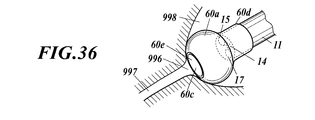
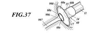
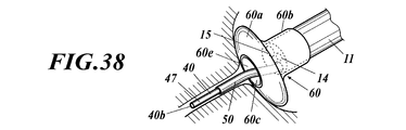
- the invention according to Claim 23 provides the endoscope system according to any one of Claims 6 to 22, wherein a distal end of the insertion portion is formed in a spherical shape or an umbrella shape. .
- the invention according to claim 24 is the method of using the endoscope system according to any one of claims 6 to 23, wherein the hydrophilic portion is wetted with the liquid by supplying the liquid to the channel, A method of use is provided, wherein the insertion portion is inserted into the channel, the distal end of the insertion portion is protruded from the distal end of the channel, and the distal end of the insertion portion is inserted into a tube. .
- the invention according to claim 25 is the method of using the endoscope system according to any one of claims 7 to 9, wherein the liquid is supplied to the catheter through the hemostasis valve by the liquid feeding device. Wetting the hydrophilic portion with the liquid, allowing the insertion portion to enter the catheter, protruding the distal end of the insertion portion from the distal end of the catheter and the channel, and connecting the distal end of the insertion portion to the tube.
- the method of use is characterized by being inserted in
- the invention according to claim 26 is the method of using the endoscope system according to claim 19, wherein the hydrophilic portion is wetted with the liquid by supplying the liquid to the channel, and the insertion portion enters the channel.
- the distal end of the insertion portion protrudes from the distal end of the channel, and the distal end of the insertion portion is inserted into the tube, and an ultrasonic diagnostic apparatus is used for the insertion of the distal end of the tube.
- a method of use characterized by observing the inside is provided.
- the invention according to claim 27 is the method of using the endoscope system according to claim 22, wherein the hydrophilic portion is wetted by the liquid by supplying the liquid to the channel, and the insertion portion enters the channel.
- the distal end of the insertion portion protrudes from the distal end of the channel, and the distal end of the insertion portion is inserted into the tube, and an ultrasonic diagnostic apparatus is used for the insertion of the distal end of the tube.
- a method of use characterized by observing the inside is provided.
- the hydrophilic portion gets wet with the liquid, slime is generated on the surface of the hydrophilic portion, and the distal end of the insertion portion of the fiberscope can be easily inserted into the thin tube.
- FIG. 1 is a perspective view of an endoscope system according to a first embodiment of the present invention. It is drawing which shows the use condition of the endoscope system which concerns on the embodiment. It is a perspective view of the fiberscope which concerns on the same embodiment. It is a front view of the distal end of the fiberscope which concerns on the same embodiment. It is a front view of the distal end of the fiberscope which concerns on the same embodiment. It is a side view of the hemostasis valve concerning the embodiment. It is a schematic sectional drawing of the input port of the hemostasis valve concerning the embodiment. It is a schematic perspective view of the input port of the hemostasis valve concerning the embodiment. It is a schematic sectional drawing of the input port of the hemostasis valve concerning the embodiment.
- FIG. 10 is a perspective view showing a distal portion of a fiberscope according to Modification 7.
- FIG. 10 is a perspective view for explaining a state where an ultrasonic marker is embedded in a fiberscope according to Modification 7.
- FIG. 10 is a schematic side view of a fiberscope according to Modification 7.
- FIG. 10 is a schematic side view of a fiberscope according to Modification 7.
- FIG. 10 is a schematic side view of a fiberscope according to Modification 7.
- FIG. 10 is a schematic side view of a fiberscope according to Modification 7.
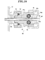
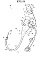
- FIG. 1 is a perspective view of the endoscope system 1.
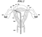
- FIG. 2 is a diagram showing a use state of the endoscope system 1.
- the endoscope system 1 is an oviduct scope guide device.
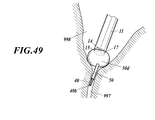
- the endoscope system 1 is a device that guides the second endoscope 30 that is an oviduct scope from outside the body to the oviduct 997 via the vagina 999 and the uterus 998.
- This endoscope system 1 is a fallopian tube observation apparatus for observing the fallopian tube 997, and an operator (a doctor or the like) first observes the vagina 999 and the uterus 998 using this endoscope system 1. -Diagnose and secondarily observe and diagnose the fallopian tube 997 and fallopian tube 995.
- the endoscope system 1 includes a first endoscope 10, a second endoscope 30, a catheter 50, a hemostasis valve 55, a liquid feeding device 70, a vaginal opening device, and the like.
- FIG. 3 is a perspective view of the second endoscope 30 as a fiberscope.
- the second endoscope 30 is an oviduct mirror.
- the second endoscope 30 includes a holding part (gripping part) 31, a disposable insertion part 40, and the like.
- proximal refers to the side close to the holding unit 31 or the holding unit 12 described later
- distal refers to the side far from the holding unit 31 or the holding unit 12 described below.
- the operator operates the second endoscope 30 with the holding unit 31.
- An eyepiece part (finder) 32 is provided on the holding part 31.
- an eyepiece optical system (eyepiece lens) 33 including one or a plurality of lenses is provided.
- the holding part 31 is provided in a case shape. Various members are accommodated in the holding portion 31, and these members are attached to the holding portion 31. Specifically, the illumination light source 34, the condensing lens 34a, the ultrasonic oscillator 35, the positioning mechanism 36, the power source 37, and the like are accommodated in the holding unit 31, and the illumination light source 34, the condensing lens 34a, the ultrasonic oscillator 35, The positioning mechanism 36, the power source 37, and the like are attached to the holding unit 31.
- the power source 37 is a battery (primary battery) or a chargeable / dischargeable battery (secondary battery).
- the power source 37 supplies power to the illumination light source 34 and the ultrasonic oscillator 35.
- the illumination light source 34 emits illumination light (mainly light in the visible light band).
- the ultrasonic oscillator 35 vibrates and emits ultrasonic waves. Note that the ultrasonic oscillator 35 may be omitted.
- the insertion portion 40 is provided in a cable shape (linear shape).
- a proximal end (base end) 40 a of the insertion portion 40 is connected to the holding portion 31 by the positioning mechanism 36, and the insertion portion 40 extends from the holding portion 31.
- the positioning mechanism 36 is a connector having a screw or an engaging portion.
- the positioning mechanism 36 locks the proximal end 40 a of the insertion portion 40 to the holding portion 31.
- the lock by the positioning mechanism 36 can be released, and the proximal end 40 a of the insertion portion 40 can be detached from the holding portion 31. Therefore, the insertion part 40 can be attached to and detached from the holding part 31.
- the insertion part 40 has flexibility.
- the insertion part 40 can be bent according to the shape of the hole into which the insertion part 40 is inserted.
- the insertion unit 40 takes in the illumination light emitted from the illumination light source 34 and collected by the condenser lens 34a into the proximal end 40a.
- the insertion part 40 guides the illumination light taken into the proximal end 40a from the proximal end 40a to the distal end (tip) 40b.
- the insertion portion 40 is guided to the distal end 40b and emits illumination light forward from the distal end 40b. Accordingly, the distal end 40b of the insertion portion 40 illuminates the vicinity of the distal end 40b of the insertion portion 40.
- the insertion unit 40 captures an image in front of the distal end 40b into the distal end 40b.
- the insertion unit 40 transmits the image captured by the distal end 40b from the distal end 40b to the proximal end 40a.
- the insertion unit 40 projects the image transmitted to the proximal end 40a from the proximal end 40a to the eyepiece optical system 33. Accordingly, the image is projected by the eyepiece optical system 33 onto the eyes of an operator looking through the eyepiece optical system 33.
- the insertion part 40 takes in the ultrasonic wave emitted from the ultrasonic oscillator 35 to the proximal end 40a and propagates the ultrasonic wave to the distal end 40b.
- the distal end 40b of the insertion portion 40 vibrates at the ultrasonic frequency. Hydrophilicity is imparted to the surface of the distal portion 40 c of the insertion portion 40. Therefore, the liquid tends to get wet on the surface of the distal portion 40 c of the insertion portion 40.
- the insertion portion 40 is formed by an extrusion method.
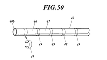
- FIG. 4 is a front view showing the surface of the distal end 40 b of the insertion portion 40.
- the insertion unit 40 includes a first optical fiber bundle 41, a second optical fiber bundle (light guide) 42, an ultrasonic transmission member 43, a first inner protective layer 44, a second It has an inner protective layer 45, a sheath 46 and a hydrophilic portion 47.
- the first optical fiber bundle 41 transmits an image, and the second optical fiber bundle 42 guides illumination light.
- the first optical fiber bundle 41 is composed of a plurality of optical fibers that are bundled (for example, bundled in a circular cross section).
- the second optical fiber bundle 42 includes a plurality of optical fibers bundled (for example, bundled in a crescent cross section).
- the ultrasonic transmission member 43 is a linear member.
- the ultrasonic transmission member 43 can be recognized by the ultrasonic diagnostic apparatus.
- the acoustic impedance of the ultrasonic transmission member 43 is significantly different from the acoustic impedance of a biological tissue (specifically, female genitals), and the ultrasonic transmission member 43 and the biological tissue can be distinguished by an ultrasonic diagnostic apparatus.
- the acoustic impedance of the ultrasonic transmission member 43 is significantly different from the acoustic impedance of the optical fiber bundles 41 and 42, the inner protective layers 44, 45, and 48, the sheath 46, and the hydrophilic portion 47 (see FIGS. 4 and 5).
- the bundles 41 and 42, the inner protective layers 44, 45, and 48, the sheath 46, the hydrophilic portion 47, and the ultrasonic transmission member 43 can be distinguished by the ultrasonic diagnostic apparatus.
- the ultrasonic transmission member 43 is a metal wire made of stainless steel (SUS304), gold, platinum, palladium alloy, or other metal. If the ultrasonic oscillator 35 is omitted, the ultrasonic transmission member 43 may be omitted.
- the first inner protective layer 44 covers the first optical fiber bundle 41.
- the second inner protective layer 45 covers the second optical fiber bundle 42.
- the first optical fiber bundle 41 and the second optical fiber bundle 42 are juxtaposed at a distance from each other.
- the ultrasonic transmission member 43 is arranged in parallel with the first optical fiber bundle 41 and the second optical fiber bundle 42.
- the first optical fiber bundle 41, the second optical fiber bundle 42, and the ultrasonic transmission member 43 extend along the insertion portion 40 from the distal end 40 b of the insertion portion 40 to the proximal end 40 a of the insertion portion 40. .
- the sheath 46 covers the first internal protective layer 44, the second internal protective layer 45, and the ultrasonic transmission member 43, and the first 46 from the outside of the first internal protective layer 44 and the second internal protective layer 45.
- the optical fiber bundle 41 and the second optical fiber bundle 42 are protected.
- the hydrophilic portion 47 is a layer that imparts hydrophilicity to the surface of the distal portion 40 c of the sheath 46. That is, the hydrophilic portion 47 covers the outer peripheral surface of the distal portion 40 c of the sheath 46.
- the hydrophilic portion 47 may cover at least the distal portion 40 c of the sheath 46. For example, the hydrophilic portion 47 may cover the entire outer peripheral surface of the sheath 46.
- the hydrophilic portion 47 is made of a hydrophilic material.
- a material is applied as a material for the hydrophilic portion 47.
- the matters described in these publications are incorporated by reference as matters described in this specification.
- the insertion unit 40 can be observed with an ultrasonic diagnostic apparatus.
- an ultrasonic marker is formed in the insertion portion 40 (particularly, the distal portion 40c of the insertion portion 40).
- the ultrasonic marker may be embedded in the insertion portion 40 or may be formed on the outer peripheral surface of the insertion portion 40 (the outer peripheral surface of the sheath 46).
- the ultrasonic marker refers to a member / material that can be detected by an ultrasonic diagnostic apparatus. The configuration in which the insertion unit 40 can be observed by the ultrasonic diagnostic apparatus will be described in detail later (see Modification 7).
- the ultrasonic marker formed in the insertion unit 40 can be recognized by an ultrasonic diagnostic apparatus.
- the acoustic impedance of the ultrasonic marker is greatly different from the acoustic impedance of a biological tissue (specifically, female genitals), and the ultrasonic marker and the biological tissue can be distinguished by an ultrasonic diagnostic apparatus.
- the material of the ultrasonic marker is stainless steel (SUS304), gold, platinum, palladium alloy or other metal.
- the ultrasonic marker may be formed on the outer peripheral surface of the sheath 46 by applying a material that can be recognized by the ultrasonic diagnostic apparatus (see Japanese Patent No. 4349546).
- Japanese Patent No. 4349546 Japanese Patent No. 4349546
- the first optical fiber bundle 41, the second optical fiber bundle 42, the ultrasonic transmission member 43, the first inner protective layer 44, the second inner protective layer 45, the sheath 46, and the hydrophilic portion 47 have flexibility.
- the form of the insertion portion 40 may be as shown in FIG.
- FIG. 5 is a front view showing a surface of the distal end 40b of the insertion portion 40 having a form different from that of the insertion portion 40 shown in FIG. Parts corresponding to each other between the insertion portion 40 shown in FIG. 4 and the insertion portion 40 shown in FIG. 5 are denoted by the same reference numerals.
- the insertion portion 40 includes a first optical fiber bundle 41, a second optical fiber bundle 42, a sheath 46, a hydrophilic portion 47, and an internal protective layer 48.
- the inner protective layer 48 covers the first optical fiber bundle 41, and the second optical fiber bundle 42 is bundled so as to surround the first optical fiber bundle 41 outside the inner protective layer 48.
- the second optical fiber bundle 42 is composed of a plurality of optical fibers bundled in a circular ring shape in cross section.
- the sheath 46 covers the second optical fiber bundle 42 and protects the second optical fiber bundle 42.
- the hydrophilic portion 47 covers the outer peripheral surface of the distal portion 40 c of the sheath 46.
- the ultrasonic transmission member 43 may or may not be provided inside the insertion portion 40 shown in FIG.
- the configuration of the distal end 40b of the insertion portion 40 shown in FIG. 5 is the same as the configuration of the distal end 40b of the insertion portion 40 shown in FIG. 4 and 5, the distal end (tip) of the first optical fiber bundle 41 is exposed at the distal end 40 b of the insertion portion 40.
- the imaging lens is provided in the sheath 46 before the distal end of the first optical fiber bundle 41, and the imaging lens is exposed at the distal end 40 b of the insertion portion 40. The imaging lens forms an image in front of the distal end of the first optical fiber bundle 41 on the distal end of the first optical fiber bundle 41.
- the distal end (tip) of the second optical fiber bundle 42 is exposed at the distal end 40b of the insertion portion 40.
- the projection lens is provided on the sheath 46 before the distal end of the second optical fiber bundle 42, and the lens is exposed at the distal end 40 b of the insertion portion 40.
- the projection lens projects illumination light emitted from the distal end of the second optical fiber bundle 42 to the front of the distal end of the second optical fiber bundle 42.
- the imaging lens and the projection lens may be shared as one lens.
- the proximal end (base end) of the first optical fiber bundle 41 is exposed at the proximal end 40 a of the insertion portion 40. That is, the proximal end of the first optical fiber bundle 41 is not covered with the first inner protective layer 44 and the sheath 46. The same applies to the proximal end of the second optical fiber bundle 42.
- the configuration of the proximal end 40a of the insertion portion 40 shown in FIG. 5 is the same as the configuration of the proximal end 40a of the insertion portion 40 shown in FIG. 4 and 5, when the proximal end 40 a of the insertion portion 40 is connected to the holding portion 31 by the positioning mechanism 36 as shown in FIG. 1, the positioning mechanism 36 is connected to the first optical fiber bundle 41.
- the position of the proximal end is determined, and the proximal end of the first optical fiber bundle 41 is opposed to the eyepiece optical system 33.
- the positioning mechanism 36 determines the position of the proximal end of the second optical fiber bundle 42 and makes the proximal end of the second optical fiber bundle 42 face the condenser lens 34 a and the illumination light source 34.
- the positioning mechanism 36 determines the position of the proximal end of the ultrasonic transmission member 43 and connects the proximal end of the ultrasonic transmission member 43 to the ultrasonic oscillator 35.
- the first endoscope 10 is a hysteroscope (hysteroscope).
- the first endoscope 10 is described in US Pat. No. 4,911,148, US Pat. No. 4,836,189, US Pat. No. 4,777,612, US Pat. No. 4,461,634, US Pat.
- the first endoscope 10 is a viewing mirror described in International Publication No. 95/24149.
- the matters described in these publications are incorporated by reference as matters described in this specification.
- the first endoscope 10 is a fiber scope or a video scope.
- the first endoscope 10 includes an insertion part 11 and a holding part 12.
- the proximal end (base end) of the insertion portion 11 is connected to the holding portion 12, and the insertion portion 11 extends from the holding portion 12.
- the first endoscope 10 is a soft mirror, and the insertion portion 11 has flexibility.
- the distal portion 11b of the insertion portion 11 has a bending function, and the distal portion 11b of the insertion portion 11 can be remotely bent by an operator. For example, when the operator operates the holding portion 12, the distal portion 11 b of the insertion portion 11 performs a bending operation, and the orientation of the distal end (tip) 11 a of the insertion portion 11 can be changed.
- An eyepiece (finder) 13 is provided on the holding unit 12.
- An image in front of the distal end 11a of the insertion part 11 is projected on the eyepiece part 13, and the operator can observe and diagnose the front of the distal end 11a of the insertion part 11 by looking into the eyepiece part 13. it can.
- the first endoscope 10 is a fiberscope
- an objective lens as an image input unit 14 is provided at the distal end 11 a of the insertion unit 11, and an optical fiber bundle for images travels far inside the insertion unit 11 and the holding unit 12. Wiring is performed from the distal end 11 a to the eyepiece 13, and an eyepiece is provided on the eyepiece 13.
- An image in front of the distal end 11a of the insertion portion 11 is formed on the distal end of the optical fiber bundle by the objective lens, the image is transmitted to the proximal end of the optical fiber bundle by the optical fiber bundle, and the image is emitted by the eyepiece. And projected onto the eyes of the operator.
- a small electronic camera (the electronic camera is composed of an objective lens, an image sensor, etc.) as the image input unit 14 is provided at the distal end 11 a of the insertion unit 11.
- the transmission cable is wired from the distal end 11 a to the eyepiece 13 in the insertion portion 11 and the holding portion 12, and an eyepiece and a display element are provided in the eyepiece 13.
- An image in front of the distal end 11a of the insertion portion 11 is captured by an electronic camera, the image is transmitted as an image signal to a display element by a transmission cable, the image is displayed by the display element, and the displayed image is an eyepiece. Is projected onto the operator's eyes and the like.
- the transmission cable wired from the image input unit 14 to the holding unit 12 is further wired to a display device outside the holding unit 12, and the image signal of the image captured by the image input unit 14 is externally displayed by the transmission cable.
- the image may be transmitted to the device and the image displayed on the display device.
- the display element and the eyepiece unit 13 may be provided in the holding unit 12 or may not be provided.
- the illumination light is emitted from the illumination unit 15 at the distal end 11a of the insertion unit 11.
- An illumination light source 16 is provided in the holding unit 12, an optical fiber or an optical fiber bundle is wired in the holding unit 12 and the insertion unit 11 from the illumination light source 16 to the illumination unit 15, and a distal end of the optical fiber or the optical fiber bundle or an illumination lens is inserted in the insertion unit. 11, the distal end of an optical fiber or optical fiber bundle or an illumination lens is the illumination unit 15.
- the illumination light source 16 When the illumination light source 16 is turned on, the light emitted from the illumination light source 16 propagates to the illumination unit 15 through an optical fiber or an optical fiber, and the light is emitted from the illumination unit 15.
- the illumination light source 16 may be provided at the distal end 11 a of the insertion unit 11, and the illumination light source 16 may be the illumination unit 15.
- the insertion part 11 of the endoscope 10 can be observed with an ultrasonic diagnostic apparatus.
- the first endoscope 10 is a tubular structure having a channel 17 as a hollow. That is, the channel 17 is provided in the insertion portion 11 along the longitudinal direction of the insertion portion 11, one end (proximal end) of the channel 17 opens at the surface of the holding portion 12, and the other end (distal end) of the channel 17. Opens at the distal end 11 a of the insertion portion 11. Since the insertion portion 11 is flexible, the first endoscope 10 is a flexible tubular structure.
- the channel 17 is a forceps channel.
- a channel 18 is formed inside the holding portion 12, one end 18 a of the channel 18 opens at the surface of the holding portion 12, and the other end 18 b of the channel 18 joins the middle portion of the channel 17.
- the opening of one end 18a of the channel 18 is closed by a cap or the like, or the port adapter 19 is attached to the opening.
- the port adapter 19 is provided with a valve mounting portion 19a, and various valves can be mounted on the valve mounting portion 19a. Further, the port adapter 19 is provided with an inlet port 19b, and this inlet port 19b is provided with a syringe (syringe), a pump, a perfusion system (the perfusion system is composed of a pump or the like) or an infusion bag (an infusion bag) via a tube. It is connected.
- the catheter 50 is inserted into the channel 17 from the opening at one end (proximal end) of the channel 17, and the distal portion 50 a of the catheter 50 extends from the opening on the opposite side of the channel 17.
- the catheter 50 is a tubular structure having a hollow, and the catheter 50 is provided in a tubular shape.
- the catheter 50 is a flexible tubular structure, and the catheter 50 is flexible. Since the catheter 50 is inserted into the channel 17 of the first endoscope 10, the first endoscope 10 and the catheter 50 constitute a double tubular structure.
- the catheter 50 (particularly, the distal portion 50a of the catheter 50) can be observed by an ultrasonic diagnostic apparatus.
- an ultrasonic marker is formed on the catheter 50 (particularly, the distal portion 50a of the catheter 50).
- the ultrasonic marker may be embedded in the catheter 50 or may be formed on the outer peripheral surface of the catheter 50. In any case, the hollow of the catheter 50 is not blocked by the ultrasonic marker.
- FIG. 6 is a side view of the hemostasis valve 55.
- the hemostasis valve 55 has a configuration similar to a three-way stopcock.
- the hemostasis valve 55 includes an output port 55a, a first input port 55b, a second input port 55c, a main body portion 55d, a flow path 55e, and the like.
- a first input port 55b, a second input port 55c, and a second output port 55a are provided in the main body 55d.
- the flow path 55e is a hollow provided inside the main body 55d.
- the channel 55e and the main body 55d are provided in a Y shape. That is, a part of the flow path 55e is linearly provided from the first input port 55b to the first output port 55a, the first input port 55b is provided at one end of the linearly provided portion, and the other end is provided.
- the first output port 55a is provided, the flow path 55e is branched in the middle between the first input port 55b and the first output port 55a, and the second input port 55c is provided at the end of the divided portion. Yes.
- the output port 55a of the hemostasis valve 55 is connected to the proximal end of the catheter 50.
- the insertion portion 40 of the second endoscope 30 is inserted into the first input port 55b of the hemostasis valve 55, the insertion portion 40 is passed through the hemostasis valve 55 and the catheter 50, and the distal end 40b of the insertion portion 40 is inserted. Extends from the opening at the distal end of the catheter 50.
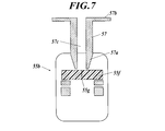
- FIG. 7 to 11 are drawings for explaining the first input port 55b of the hemostasis valve 55.
- FIG. The fluid in the flow path 55e does not leak from the first input port 55b. That is, the first input port 55b is in a closed state, and the fluid in the flow path 55e does not leak to the outside through the first input port 55b. Further, when the insert is inserted into the first input port 55b, the insert is held in the first input port 55b and there is no gap in the first input port 55b, so that the fluid in the flow path 55e is transferred to the first input port 55b. No leakage outside through 55b.
- the first input port 55b is provided with a check valve 55f made of an elastic member such as rubber.
- the check valve 55f has a cut 55g.
- the cut 55g is closed by the elastic force of the check valve 55f, and the fluid in the flow path 55e does not leak through the cut 55g.
- the notch 55g opens against the elastic force of the check valve 55f, and the insert is inserted into the notch 55g of the check valve 55f. There is no gap between 55f. Therefore, the fluid in the flow path 55e does not leak.
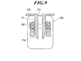
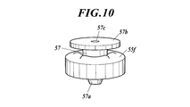
- the cylindrical member 57 When inserting the insertion portion 40 of the second endoscope 30 into the first input port 55b, the cylindrical member 57 is used.
- the cylindrical member 57 is provided in a cylindrical shape having a hollow 57 c, one end portion 57 a of the cylindrical member 57 is tapered, and a flange 57 b is provided at the other end portion of the cylindrical member 57.
- the notch 55g of the check valve 55f opens, and the cylindrical member 57 is held by the notch 55g of the check valve 55f. (See FIGS. 9 and 10). Since there is no gap between the cylindrical member 57 and the check valve 55f, no fluid leaks at this portion.
- the operator With the tubular member 57 inserted into the check valve 55f, the operator inserts the insertion portion 40 of the second endoscope 30 into the hollow 57c of the tubular member 57 and the first input port 55b.
- the notch 55g of the check valve 55f is closed by the elastic force of the check valve 55f, and the insertion portion 40 of the second endoscope 30 is moved to the check valve. It is held in the notch 55g of 55f (see FIG. 11). Since there is no gap between the insertion portion 40 of the second endoscope 30 and the check valve 55f, no fluid leaks at this portion.
- the tubular member 57 is also used when the insertion portion 40 of the second endoscope 30 is pulled out from the first input port 55b. That is, a doctor or the like inserts the cylindrical member 57 into the check valve 55f, and in that state, pulls out the insertion portion 40 of the second endoscope 30 from the hollow 57c of the cylindrical member 57 and the first input port 55b. Then, the tubular member 57 is pulled out from the check valve 55f.
- the number of check valves 55f may be one or more. When there are a plurality of check valves 55f, the plurality of check valves 55f are overlapped so that fluid leakage can be reliably prevented.
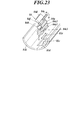
- FIG. 12 is a perspective view of a fixture 59 for fixing the hemostasis valve 55 to the holding portion 12.
- FIG. 13 is a perspective view showing the hemostasis valve 55, the fixture 59, the holding portion 12, and the like.
- the hemostasis valve 55 is held by the holding portion 12 by a fixture 59.
- the fixture 59 is a clip pair. That is, the fixture 59 has a first clip 59a and a second clip 59b.
- the first clip 59a is made of a C-shaped elastic member
- the second clip 59b is made of a C-shaped elastic member.
- the open portion of the first clip 59a is opposite to the open portion of the second clip 59b, and the second clip 59b is connected to the first clip 59a.
- the first clip 59a holds the holding portion 12 so as to sandwich the holding portion 12
- the second clip 59b holds the main body portion 55d of the hemostasis valve 55 so as to sandwich the main body portion 55d of the hemostasis valve 55. Accordingly, the hemostasis valve 55 is fixed to the holding portion 12.
- the second input port 55 c is connected to one end of a flexible catheter 58, and the other end of the catheter 58 is connected to the liquid delivery device 70.
- the liquid feeding device 70 stores liquid (for example, sterilized water and physiological saline) and sends the liquid to the catheter 58, hemostasis valve 55, and catheter 50.
- the liquid feeding device 70 is an electric pump or a manual pump.
- the liquid feeding device 70 is a manual or electric syringe pump.
- the catheter 58 can be attached to and detached from the liquid feeding device 70.
- the insertion part 40, the catheter 50, the hemostasis valve 55, the catheter 58 and the tubular member 57 are disposable.
- the unused insertion part 40, the catheter 50, the hemostasis valve 55, the catheter 58, and the cylindrical member 57 are packed in an assembled state. That is, as shown in FIGS. 9 and 10, the cylindrical member 57 is attached to the check valve 55 f of the first input port 55 b, and the insertion portion 40 is a hollow 57 c of the cylindrical member 57, a hemostasis valve.
- the insertion portion 40, the catheter 50, the hemostasis valve 55, the catheter 58, and the tubular member 57 are packed in a state of being inserted into the flow path 55 e of 55 and the catheter 50. Further, in a state where the insertion portion 40, the catheter 50, the hemostasis valve 55, the catheter 58 and the tubular member 57 are packed, the catheter 50 is wound together with the insertion portion 40 in a ring shape.
- a method for using the endoscope system 1 will be described, and a diagnosis method using the endoscope system 1 will be described.
- An operator such as a doctor removes the insertion portion 40, the catheter 50, the hemostasis valve 55, the catheter 58 and the tubular member 57 packed in the package from the package.
- the insertion part 40, the catheter 50, the hemostasis valve 55, the catheter 58, and the cylindrical member 57 may be packed separately. In this case, after inserting the insertion part 40, the catheter 50, the hemostasis valve 55, the catheter 58 and the cylindrical member 57 from each package, these are assembled.
- the tubular member 57 is inserted into the check valve 55f of the first input port 55b, the catheters 50 and 58 are connected to the hemostasis valve 55, and the insertion portion 40 is connected to the hollow 57c of the tubular member 57 and the hemostasis valve 55. Are inserted into the flow path 55e and the catheter 50.
- the proximal end 40 a of the insertion portion 40 is attached to the holding portion 31, and the proximal end 40 a of the insertion portion 40 is fixed to the holding portion 31 by the positioning mechanism 36.
- the distal end 40 b of the insertion portion 40 is aligned with the distal end of the catheter 50 by moving the insertion portion 40 forward or backward, or the distal end 40 b of the insertion portion 40 is drawn into the catheter 50.
- the tubular member 57 is pulled out from the check valve 55f and the first input port 55b, the check valve 55f and the first input port 55b are closed, and the insertion portion 40 is fixed by the check valve 55f.
- the catheter 58 is connected to the liquid feeding device 70 and a liquid such as a sterilizing solution is supplied to the liquid feeding device 70.
- the opening of one end 18a of the channel 18 is closed with a cap or the like, or the port adapter 19 is attached to the opening.
- a valve is attached to the valve attachment portion 19a, and a syringe, a pump, a perfusion system or an infusion bag is connected to the inlet port 19b.
- a liquid such as a sterilizing solution is supplied to the syringe.
- a liquid such as a sterilizing liquid is supplied to a tank (liquid supply source) of a pump or a perfusion system. Liquid such as sterilization liquid is stored in the drip bag.
- the operator inserts the catheter 50 together with the insertion portion 40 into one end (proximal end) of the channel 17, and the distal end 40 b of the insertion portion 40 and the distal end of the catheter 50 are connected to the other end (distant end) of the channel 17.
- the insertion portion 40 and the catheter 50 are advanced into the channel 17 so as not to come out from the distal end.
- the hemostasis valve 55 is fixed to the holding portion 12 by the fixing tool 59.
- vaginal opening device (Cusco, vagina tube) into the vagina 999, and opens the vaginal opening and vagina 999 with the open vaginal device.
- the vaginal opening may or may not be provided with a holder for holding the first endoscope 10.
- the vaginal opening device provided with the holder will be described in detail later (refer to the sixth to ninth embodiments). It is not necessary to use a vaginal opening device.
- the operator inserts the insertion portion 11 into the vaginal opening and introduces the insertion portion 11 into the vagina 999 and the uterus 998 in this order.
- the insertion unit 11 since the illumination light source 16 is turned on, the illumination light emitted from the illumination light source 16 is guided to the illumination unit 15 by an optical fiber or an optical fiber bundle, and the illumination light is emitted from the illumination unit 15.
- the image in front of the illumination unit 15 is captured by the image input unit 14, the operator can perform observation and diagnosis in front of the image input unit 14 by looking into the eyepiece unit 13. The operator introduces the insertion portion 11 into the vagina 999 and the uterus 998 while performing such observation and diagnosis.
- the fallopian tube 996 refers to the end of the fallopian tube 997 that opens in the inner wall of the uterus 998.
- the insertion portion 11 and / or the holding portion 12 of the first endoscope 10 are attached to the holder, and the first endoscope 10 is fixed to the vaginal opening device.
- the holder preferably biases (pushes out) the insertion portion 11 or the holding portion 12 or both in the direction in which the insertion portion 11 is inserted into the vagina 999.
- the operator enters the catheter 50 into the channel 17, the distal end of the catheter 50 protrudes from the distal end of the channel 17, and the distal end of the catheter 50 is slightly moved to the fallopian tube 996 of the fallopian tube 997. Insert into.
- the distal end of the catheter 50 protrudes from the distal end of the channel 17, liquid is fed by the liquid feeding device 70 as necessary, and the liquid is inside the channel 17 and inside the catheter 50.
- the fluid is allowed to flow and the liquid is ejected from the distal end of the catheter 50. If it does so, the part 50a of the distal side of the catheter 50 will slip easily with respect to the oviduct 997 with the ejected liquid, and it will become easy to insert the distal end of the catheter 50 in the oviduct 997. Even if the liquid is supplied to the flow path 55e of the hemostasis valve 55 by the liquid feeding device 70, the check valve 55f is closed, so that the liquid does not leak from the first input port 55b. Since the catheter 50 is inserted into the channel 17, the liquid flows inside the channel 17 and inside the catheter 50.
- the ultrasonic oscillator 35 when the distal end of the catheter 50 is protruded from the distal end of the channel 17, the ultrasonic wave is propagated to the distal end 40 b of the insertion portion 40 by the ultrasonic transmission member 43.
- the distal end of the catheter 50 is ultrasonically vibrated together with the distal end 40b of the insertion portion 40. It becomes easy to insert the distal end of the catheter 50 into the fallopian tube 997.
- the liquid is fed by the liquid feeding device 70, and the liquid is ejected from the distal end of the catheter 50.
- the ejected liquid is filled in the oviduct 997.
- the oviduct 997 becomes straight, it becomes easy to introduce the insertion part 40.
- surroundings of the distal end 40b of the insertion part 40 are satisfy
- the liquid is supplied to the channels 18 and 17 by a syringe, a pump, a perfusion system or an infusion bag together with the liquid feeding by the liquid feeding device 70. May be.
- the liquid is supplied to the channels 18 and 17, the liquid is ejected from the distal end of the channel 17.
- the distal portion of the catheter 50 and the distal portion 40c of the insertion portion 40 are wetted by the liquid. If the catheter 50 is inserted into the proximal end of the channel 17 via packing or the like, the liquid supplied to the channels 17 and 18 can be prevented from being ejected from the proximal end of the channel 17.
- the operator inserts one end 57a of the cylindrical member 57 into the cut 55g of the check valve 55f. Then, the notch 55g of the check valve 55f is opened, the check valve 55f is separated from the insertion portion 40, and the fixing of the insertion portion 40 by the check valve 55f is released. Therefore, the insertion portion 40 can be taken in and out of the hollow 57 c of the cylindrical member 57.
- the operator causes the insertion portion 40 to enter the catheter 50, the distal end 40 b of the insertion portion 40 protrudes from the distal end of the catheter 50, and the distal end 40 b of the insertion portion 40 is inserted into the oviduct 997. . Then, the operator further inserts the insertion portion 40 into the catheter 50 and introduces the distal end 40b of the insertion portion 40 as far as possible into the deepest of the fallopian tube 997, up to the fallopian tube 995.
- the liquid in the fallopian tube 997 (liquid ejected from the catheter 50) wets well with the hydrophilic portion 47 of the insertion portion 40 and the liquid is not repelled from the hydrophilic portion 47.
- slime occurs on the surface of the hydrophilic portion 47. Accordingly, the distal portion 40c of the insertion portion 40 is easily slipped with respect to the fallopian tube 997 by the liquid, and the distal end 40b of the insertion portion 40 is easily introduced into the fallopian tube 997 and the fallopian tube 995.
- the liquid feeding device 70 When the insertion portion 40 is inserted into the oviduct 997, the liquid is fed by the liquid feeding device 70 (when the port adapter 19 is attached to the opening of the one end 18a of the channel 18, the liquid feeding device 70 feeds the liquid.
- liquid may be supplied to the channels 18, 17 by syringe, pump, perfusion system or infusion bag), and the liquid may be injected or refilled into the oviduct 997.
- Either the step of inserting the insertion portion 40 into the oviduct 997 or the step of blowing the liquid from the distal end of the catheter 50 by the liquid delivery device 70 may be performed first, or these steps may be performed simultaneously.
- a guide wire is inserted into the fallopian tube, then a catheter is inserted into the fallopian tube using the guidewire, then the guidewire is pulled out, and then the catheter is The oviduct mirror was inserted into the fallopian tube.
- the distal portion 40c of the insertion portion 40 can be inserted into the oviduct 997. This is because the hydrophilic portion 47 provided in the distal portion 40c of the insertion portion 40 is easily wetted by the liquid, and the hydrophilic portion 47 is slidable with respect to the oviduct 997.
- the ultrasonic oscillator 35 is activated when the distal end 40b of the insertion portion 40 is inserted into the fallopian tube 997 or the fallopian tube 995 or both, the ultrasonic wave is transmitted to the distal portion of the insertion portion 40 by the ultrasonic transmission member 43. Propagating to the end 40b, the distal end 40b of the insertion portion 40 vibrates ultrasonically. It becomes easy to insert the distal end 40 b of the insertion portion 40 into the oviduct 997.
- the illumination light source 34 Since the illumination light source 34 is turned on when the insertion portion 40 is inserted, the illumination light emitted from the illumination light source 34 is guided to the distal end of the second optical fiber bundle 42 by the second optical fiber bundle 42, Illumination light is emitted from the distal end of the second optical fiber bundle 42.
- an image in front of the distal end 40 b of the insertion portion 40 is taken into the distal end of the first optical fiber bundle 41, and the image is transmitted to the proximal end by the first optical fiber bundle 41. Therefore, the operator can observe and diagnose the fallopian tube 997 or fallopian tube 995 or both by looking into the eyepiece optical system 33 of the eyepiece 32. The operator introduces the insertion portion 40 into the fallopian tube 997 while performing such observation and diagnosis.
- the operator pulls out the insertion portion 40 from the catheter 50 and pulls out the distal end 40b of the insertion portion 40 from the fallopian tube 997.
- the liquid is blown out from the distal end of the catheter 50 by the liquid feeding device 70 (when the port adapter 19 is attached to the opening of the one end 18a of the channel 18)
- liquid may be supplied to channels 18, 17 by syringe, pump, perfusion system or infusion bag), and liquid may be injected or refilled into oviduct 997.
- an operator may observe and diagnose the fallopian tube 997 and / or fallopian tube 995 by looking into the eyepiece optical system 33 of the eyepiece part 32.
- the operator pulls out the catheter 50 from the channel 17, pulls out the distal end of the catheter 50 from the fallopian tube 996, and pulls the distal end of the catheter 50 into the channel 17.
- the operator operates the holding portion 12 to pull out the insertion portion 11 from the uterus 998 and the vagina 999 while straightening the distal portion 11 b of the insertion portion 11.
- the operator removes the fixture 59 from the holding portion 12 and removes the fixture 59 from the hemostasis valve 55. Then, the operator pulls out the catheter 50 together with the insertion portion 40 from the channel 17.
- the operator removes the proximal end 40 a of the insertion portion 40 from the holding portion 31 and removes the catheter 58 from the liquid delivery device 70. Then, the operator discards the insertion portion 40, the catheter 50, the hemostasis valve 55, the catheter 58, and the tubular member 57.
- FIG. 14 is a perspective view of the endoscope system 1A.
- FIG. 15 is a view showing a use state of the endoscope system 1A. Parts corresponding to each other between the endoscope system 1A in the second embodiment and the endoscope system 1 in the first embodiment are denoted by the same reference numerals.
- the difference between the endoscope system 1A in the second embodiment and the endoscope system 1 in the first embodiment resides in the catheter 50, the hemostasis valve 55, the catheter 58, and the liquid feeding device 70. That is, the endoscope system 1A does not include the catheter 50, the hemostasis valve 55, the catheter 58, and the liquid feeding device 70.
- the first endoscope 10 has a port adapter 19 attached to the opening of one end 18a of the channel 18, and a syringe, a pump, a perfusion system, or an infusion bag is connected to the port adapter 19 via a tube. Connected to the inlet port 19b.
- the insertion part 40 is disposable. The unused insertion part 40 is packed in the state wound by the ring shape.
- portions corresponding to each other between the endoscope system 1A in the second embodiment and the endoscope system 1 in the first embodiment are similarly provided.
- the usage method of the endoscope system 1A in the second embodiment is substantially the same as the usage method of the endoscope system 1 in the first embodiment.
- a method of using the endoscope system 1A in the second embodiment will be described.
- the operator When using the endoscope system 1A, the operator first takes out the insertion portion 40 packed in the package from the package. Next, the proximal end 40 a of the insertion portion 40 is attached to the holding portion 31, and the proximal end 40 a of the insertion portion 40 is fixed to the holding portion 31 by the positioning mechanism 36. Next, the operator inserts the insertion portion 40 into one end (proximal end) of the channel 17 so that the distal end 40b of the insertion portion 40 does not protrude from the other end (distal end) of the channel 17. 40 enters channel 17.
- the insertion portion 40 is inserted directly into the channel 17 or inserted through a valve (for example, a check valve), a packing or a plug (for example, a plug described in Japanese Utility Model Publication No. 55-70108).
- the part 40 is inserted into the channel 17.
- the insertion portion 40 When using a valve, packing, or the like, the insertion portion 40 is passed through a valve (for example, a check valve), packing, or the like, and when the insertion portion 40 is inserted into the channel 17, the valve, the packing, or the like is inserted into the channel 17. Fit into the opening at the proximal end of the. In this way, liquid leakage at the opening at the proximal end of the channel 17 can be prevented.
- a valve for example, a check valve
- FIG. 16 is a cross-sectional view showing a plug 90 provided at one end (proximal end) of the channel 17.
- This plug 90 is shown in FIGS. 1, 2 and 3 of Japanese Utility Model Publication No. 55-70108.
- one end (proximal end) of the channel 17 opens at the protruding end of the nipple (forceps mouth portion) 12a, and a plug body (forceps mouth body) 91 is inserted into the channel 17 inside the nipple 12a.
- An elastic ring (rubber ring) 92 is sandwiched between the plug main body 91 and the nipple 12a, the fixing ring 93 is externally mounted on the plug main body 91, and the fixing ring 93 is screwed onto the outer periphery of the nipple 12a.
- the hole 91 a of the plug body 91 is connected to the nipple 12 a and communicates with the channel 17.
- An opening 91b is formed at the tip of the plug body 91, and the opening 91b communicates with the hole 91a.
- a ring-shaped elastic packing (rubber packing) 94 and a ring-shaped operation member 95 are accommodated in the opening 91b.
- the operation ring 96 is screwed onto the outer peripheral surface of the stopper main body 91, and a flange (pressing piece) 96 a is provided on the inner periphery of the operation ring 96.
- a flange (pressing piece) 96 a is provided on the inner periphery of the operation ring 96.
- the operator After inserting the insertion portion 40 into the channel 17, the operator opens the vaginal opening and vagina 999 with the open vaginal device, inserts the insertion portion 11 into the open vaginal device, and inserts the insertion portion 11 into the vagina 999 and the uterus 998 in order. Introduce.
- the insertion unit 11 since the illumination light source 16 is turned on, the illumination light emitted from the illumination light source 16 is guided to the illumination unit 15 by an optical fiber or an optical fiber bundle, and the illumination light is emitted from the illumination unit 15.
- the image in front of the illumination unit 15 is captured by the image input unit 14, the operator can perform observation and diagnosis in front of the image input unit 14 by looking into the eyepiece unit 13. The operator introduces the insertion portion 11 into the vagina 999 and the uterus 998 while performing such observation and diagnosis.
- the operator operates the holding portion 12 to bend the distal portion 11 b of the insertion portion 11 and direct the distal end 11 a of the insertion portion 11 toward the fallopian tube opening 996 of the fallopian tube 997. Then, the operator operates the holding portion 12 so that the distal end 11a of the insertion portion 11 is lightly brought into contact with the oviduct opening 996 or the distal end 11a is inserted into the oviduct opening 996. At this time, a liquid may be fed by a syringe, a pump, a perfusion system, or an infusion bag, and the liquid may be ejected from the distal end of the channel 17.
- the operator inserts the insertion portion 40 into the channel 17, slightly protrudes the distal end 40 b of the insertion portion 40 from the distal end of the channel 17, and moves the distal end 40 b of the insertion portion 40 to the oviduct 997. Insert a little into the fallopian tube 996. Then, the operator temporarily stops the insertion portion 40 (see FIG. 15).
- a liquid is sent to the channel 17 by a syringe, a pump, a perfusion system, or an infusion bag, and the liquid is ejected from the distal end of the channel 17.
- This fills the oviduct 997 with liquid. If a valve or packing or the like is fitted in the opening at the proximal end of the channel 17, the liquid sent to the channel 17 by a syringe, a pump, a perfusion system or an infusion bag will not be ejected from the proximal end of the channel 17. Can be.
- the insertion portion 40 can be easily introduced in the same manner as in the first embodiment, and the periphery of the distal end 40b of the insertion portion 40 is filled with the liquid. The same is true in that the front field of view of the distal end of one optical fiber bundle 41 becomes clear.
- the operator further inserts the insertion portion 40 into the channel 17 and introduces the distal end 40b of the insertion portion 40 up to the fallopian tube 995.
- the liquid in the oviduct 997 (liquid ejected from the channel 17) is well wetted by the hydrophilic portion 47 of the insertion portion 40, and the liquid is not repelled from the hydrophilic portion 47, so that the surface of the hydrophilic portion 47 is not smooth. Arise. Therefore, it becomes easy to introduce the distal end 40b of the insertion portion 40 into the oviduct 997.
- a liquid may be fed by a syringe, a pump, a perfusion system, or an infusion bag, and the liquid may be injected or supplemented into the fallopian tube 997.
- the ultrasonic oscillator 35 may be activated.
- the operator observes and diagnoses the fallopian tube 997 and / or the fallopian tube 995 as the operator peeks into the eyepiece optical system 33 of the eyepiece 32 while further inserting the insertion portion 40 into the channel 17.
- the operator pulls out the insertion portion 40 from the channel 17, pulls out the distal end 40 b of the insertion portion 40 from the oviduct 997, and pulls the distal end 40 b of the insertion portion 40 into the channel 17.
- the liquid may be blown from the distal end of the channel 17 by a syringe, a pump, a perfusion system, or an infusion bag, and the liquid may be injected or refilled into the oviduct 997.
- the operator operates the holding portion 12 to remove the distal end 11a of the insertion portion 11 from the fallopian tube opening 996 of the fallopian tube 997 and insert it while straightening the distal portion 11b of the insertion portion 11.
- Part 11 is withdrawn from uterus 998 and vagina 999.
- the insertion portion 40 is pulled out from the channel 17.
- the proximal end 40a of the insertion portion 40 is removed from the holding portion 31, and the insertion portion 40 is discarded.
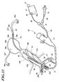
- FIG. 17 is a perspective view of the endoscope system 1B. Parts corresponding to each other between the endoscope system 1B in the third embodiment and the endoscope system 1 in the first embodiment are denoted by the same reference numerals.
- the catheter 50 is different from the endoscope system 1B in the third embodiment and the endoscope system 1 in the first embodiment. That is, the endoscope system 1B does not have the catheter 50.
- the output port 55a of the hemostasis valve 55 is connected to the opening of one end (proximal end) of the channel 17. Specifically, the output port 55a of the hemostasis valve 55 is directly screwed into, engaged with, or fitted to the opening at one end of the channel 17. Alternatively, the output port 55a of the hemostasis valve 55 is connected to the opening at one end of the channel 17 by a joint (for example, a luer lock).
- a joint for example, a luer lock
- the output port 55a of the hemostasis valve 55 is connected to the luer lock, and the luer lock is connected to the opening at one end of the channel 17, or the output port 55a of the hemostasis valve 55 is connected to the adapter.
- the adapter is threadedly engaged with or engaged with the luer lock, and the luer lock is connected to the opening at one end of the channel 17.
- the unused insertion part 40, hemostasis valve 55, catheter 58 and cylindrical member 57 are packed in an assembled state. That is, as shown in FIGS. 9 and 10, the cylindrical member 57 is mounted on the check valve 55 f of the first input port 55 b, and the insertion portion 40 is the hollow 57 c of the cylindrical member 57 and the hemostasis valve.
- the insertion portion 40, hemostasis valve 55, catheter 58, and tubular member 57 are packed in a state of being penetrated by the flow path 55 e of 55. Further, in a state where the insertion portion 40, the hemostasis valve 55, the catheter 58, and the cylindrical member 57 are packed, the insertion portion 40 is wound in a ring shape.
- portions corresponding to each other between the endoscope system 1B in the third embodiment and the endoscope system 1 in the first embodiment are similarly provided.
- the usage method of the endoscope system 1B in the third embodiment is substantially the same as the usage method of the endoscope system 1 in the first embodiment.
- a method of using the endoscope system 1B in the third embodiment will be described.
- an operator When using the endoscope system 1B in the third embodiment, an operator first takes out the insertion portion 40, hemostasis valve 55, catheter 58 and tubular member 57 from the package. Next, the operator connects the catheter 58 to the liquid feeding device 70 and supplies a liquid (for example, a sterilizing solution or physiological saline) to the liquid feeding device 70.
- a liquid for example, a sterilizing solution or physiological saline
- the insertion part 40, hemostasis valve 55, catheter 58, and the cylindrical member 57 are packed separately, the insertion part 40, hemostasis valve 55, catheter 58, and the cylindrical member 57 are taken out from each package.
- the tubular member 57 is inserted into the check valve 55f of the first input port 55b, the catheter 58 is connected to the hemostasis valve 55, and the insertion portion 40 is connected to the hollow 57c of the tubular member 57 and the hemostasis valve 55.
- the catheter 58 is connected to the liquid feeding device 70 through the flow path 55e, and a liquid such as a sterilizing solution is supplied to the liquid feeding device 70.
- the operator inserts the insertion portion 40 into one end (proximal end) of the channel 17 and connects the output port 55a of the hemostasis valve 55 to one end (proximal end) of the channel 17. Then, the insertion portion 40 is caused to enter the channel 17 so that the distal end 40 b of the insertion portion 40 does not come out of the other end (distal end) of the channel 17. Next, the tubular member 57 is removed from the check valve 55f and the first input port 55b, and the insertion portion 40 is fixed to the check valve 55f.
- the operator introduces the insertion part 11 into the vagina 999 and the uterus 998 in order through the open vagina. Then, the operator operates the holding portion 12 so that the distal end 11a of the insertion portion 11 is lightly brought into contact with the fallopian tube opening 996, or the distal end 11a is slightly inserted into the fallopian tube opening 996.
- the operator inserts the cylindrical member 57 into the check valve 55f and the first input port 55b, and releases the insertion portion 40 from the check valve 55f. Then, the operator causes the insertion portion 40 to enter the hemostasis valve 55 and the channel 17, slightly protrudes the distal end 40 b of the insertion portion 40 from the distal end of the channel 17, and moves the distal end 40 b of the insertion portion 40. Insert a little into the fallopian tube 996 of the fallopian tube 997.
- the operator removes the cylindrical member 57 from the check valve 55f and the first input port 55b, and closes the check valve 55f. Then, the liquid is fed to the channel 17 by the liquid feeding device 70, and the liquid is ejected from the distal end of the channel 17. This fills the oviduct 997 with liquid and straightens the oviduct 997. Therefore, it becomes easy to introduce the insertion part 40.
- the operator removes the cylindrical member 57 from the check valve 55f and the first input port 55b, and closes the check valve 55f. Then, the operator further inserts the insertion portion 40 into the channel 17 and introduces the distal end 40b of the insertion portion 40 up to the tubal fold 995 at the maximum. Since the liquid in the oviduct 997 is well wetted by the hydrophilic portion 47 of the insertion portion 40, the distal end 40b of the insertion portion 40 can be easily introduced into the oviduct 997.
- a liquid may be fed by the liquid feeding device 70, and the liquid may be injected or supplemented into the oviduct 997.
- the ultrasonic oscillator 35 may be activated.
- An operator introduces the distal end 40b of the insertion portion 40 into the fallopian tube 997 and fallopian tube cage 995, and looks into the ocular optical system 33 of the eyepiece unit 32, thereby causing the fallopian tube 997 and fallopian tube cage 995 or both. Observe and diagnose.
- the operator pulls the insertion portion 40, pulls out the distal end 40 b of the insertion portion 40 from the oviduct 997, and pulls the distal end 40 b of the insertion portion 40 into the channel 17. Also when pulling the insertion part 40, an operator observes and diagnoses the fallopian tube 997 or the fallopian tube 995 or both. Further, at this time, the liquid may be blown out from the distal end of the channel 17 by the liquid feeding device 70 to inject or replenish the liquid into the oviduct 997.
- the operator operates the holding portion 12 to remove the distal end 11a of the insertion portion 11 from the fallopian tube opening 996 of the fallopian tube 997 and insert it while straightening the distal portion 11b of the insertion portion 11.
- Part 11 is withdrawn from uterus 998 and vagina 999.
- the output port 55 a of the hemostasis valve 55 is removed from the opening of the channel 17, and the insertion portion 40 is pulled out from the channel 17.
- the proximal end 40 a of the insertion portion 40 is removed from the holding portion 31, and the catheter 58 is removed from the liquid feeding device 70. And the insertion part 40, hemostasis valve
- FIG. 18 is a perspective view of the endoscope system 1C. Parts corresponding to each other between the endoscope system 1C in the fourth embodiment and the endoscope system 1 in the first embodiment are denoted by the same reference numerals. The difference between the endoscope system 1C in the fourth embodiment and the endoscope system 1 in the first embodiment resides in the catheter 58 and the liquid delivery device 70. That is, the endoscope system 1C does not include the catheter 58 and the liquid feeding device 70.
- the second input port 55c is blocked by a cap or a rubber plug.
- a port adapter 19 is attached to the opening of one end 18a of the channel 18.
- the port adapter 19 is provided with a valve mounting portion 19a, and various valves can be mounted on the valve mounting portion 19a.
- the port adapter 19 is provided with an inlet port 19b, and the inlet port 19b is connected to a syringe, a pump, a perfusion system, or an infusion bag via a tube.
- portions corresponding to each other between the endoscope system 1C in the fourth embodiment and the endoscope system 1 in the first embodiment are similarly provided.
- the liquid is supplied from the distal end of the catheter 50 by supplying the liquid to the catheter 50 by the liquid feeding device 70.
- the liquid is supplied to the channels 18 and 17 by a syringe, a pump, a perfusion system, or an infusion bag, and then from the distal end of the channel 17. Spout liquid.
- the distal portion of the catheter 50 and the distal portion 40c of the insertion portion 40 are wetted by the liquid.
- the method of using the endoscope system 1C in the fourth embodiment is the same as the method of using the endoscope system 1 in the first embodiment.
- vaginal opening device 80 when the insertion part 40 of the endoscope system 1C in the fourth embodiment is introduced into the vagina 999 and the uterus 998, a vaginal opening device 80 (see FIG. 21) described later may be used (the vaginal opening device 80). And the sixth to ninth embodiments for the usage thereof).
- FIG. 19 is a perspective view of the endoscope system 1D.
- FIG. 20 is a diagram illustrating a usage state of the endoscope system 1D. Parts corresponding to each other between the endoscope system 1D in the fifth embodiment and the endoscope system 1 in the first embodiment are denoted by the same reference numerals.
- the first endoscope 10 is different from the endoscope system 1D in the fifth embodiment and the endoscope system 1 in the first embodiment. That is, in the endoscope system 1, the first endoscope 10 is a flexible endoscope, whereas in the endoscope system 1D, the first endoscope 10 is a rigid endoscope. That is, in the endoscope system 1D, the insertion portion 11 of the first endoscope 10 is rigid, and the insertion portion 11 is not curved. Further, the first endoscope 10 of the endoscope system 1D has a perfusion system.
- the endoscope system 1D does not include the second catheter 50, the hemostasis valve 55, the catheter 58, and the liquid feeding device 70. This is the same as the endoscope system 1A in the second embodiment.
- portions corresponding to each other between the endoscope system 1D in the fifth embodiment and the endoscope system 1 in the first embodiment are similarly provided.
- the usage method of the endoscope system 1D in the fifth embodiment is substantially the same as the usage method of the endoscope system 1 in the first embodiment.
- the point that the method of using the endoscope system 1D in the fifth embodiment differs from the method of using the endoscope system 1 in the first embodiment will be mainly described.
- an operator When using the endoscope system 1D in the fifth embodiment, an operator first performs a laparotomy or a laparoscopic operation, inserts the insertion portion 11 into the uterus 998, and moves the distal end 11a of the insertion portion 11 to the distal end 11a. Lightly abut the fallopian opening 996 or insert the distal end 11a into the fallopian opening 996. Then, the operator causes the insertion portion 40 attached to the holding portion 31 to enter the channel 17, slightly protrudes the distal end 40 b of the insertion portion 40 from the distal end of the channel 17, and Insert the end 40b slightly into the fallopian tube 996 of the fallopian tube 997. Then, the operator temporarily stops the insertion portion 40 (see FIG. 20).
- the liquid is fed by the perfusion system, and the liquid is ejected from the distal end of the channel 17. This fills the oviduct 997 with liquid.
- the operator further inserts the insertion portion 40 into the channel 17 and introduces the distal end 40 b of the insertion portion 40 to the fallopian tube 995.
- the operator observes and diagnoses the fallopian tube 997 and / or the fallopian tube 995 as the operator peeks into the eyepiece optical system 33 of the eyepiece 32 while further inserting the insertion portion 40 into the channel 17.
- the operator pulls out the insertion portion 40 from the channel 17, pulls out the distal end 40 b of the insertion portion 40 from the oviduct 997, and pulls the distal end 40 b of the insertion portion 40 into the channel 17.
- liquid may be blown out of the distal end of the channel 17 by the perfusion system and injected or refilled into the fallopian tube 997.
- the operator removes the distal end 11 a of the insertion portion 11 from the fallopian tube opening 996 of the fallopian tube 997 and pulls out the insertion portion 11 from the uterus 998. Then, the operator performs suturing of the abdomen.
- the insertion portion 40 is pulled out from the channel 17. Then, the proximal end 40a of the insertion part 40 is removed from the holding part 31, and the insertion part 40 is discarded.
- the insertion portion 11 and the insertion portion 40 may be inserted from the fallopian tube 995 into the fallopian tube 997.
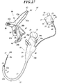
- FIG. 21 is a perspective view of an endoscope system (oviduct scope guide device) 1E.
- FIG. 22 is a view showing a use state of the endoscope system 1E. Parts corresponding to each other between the endoscope system 1E in the sixth embodiment and the endoscope system 1 in the first embodiment are denoted by the same reference numerals.
- This endoscope system 1E includes a first endoscope 10, a second endoscope 30, a catheter 50, a hemostasis valve 55, and a liquid feeding device 70, similarly to the endoscope system 1 in the first embodiment.
- the first endoscope 10, the second endoscope 30, the catheter 50, the hemostasis valve 55, and the liquid feeding device 70 in the sixth embodiment are the same as the first endoscope 10 and the second endoscope in the first embodiment. 30, the catheter 50, the hemostasis valve 55, and the liquid delivery device 70.
- the endoscope system 1E further includes an ultrasonic probe 100 (see FIG. 22).
- the ultrasonic probe 100 is connected to the main body of the ultrasonic diagnostic apparatus.
- the ultrasonic probe 100 outputs ultrasonic waves and inputs ultrasonic echoes from the outside of the ultrasonic probe 100.
- the difference between the endoscope system 1E in the sixth embodiment and the endoscope system 1 in the first embodiment resides in the vaginal opening device 80.
- This vaginal opening device 80 is provided with holders (holding tools 84 and 86).
- holders holding tools 84 and 86.
- the vaginal opening device 80 will be described in detail.
- the opening device 80 includes a first blade 81, a second blade 82, a first holder (holder) 84, a second holder (holder) 86, a first handle 87, a second handle 88, a screw 89, a fixing device 90, and It has a joint pin 91 and the like.
- a first blade (lower blade) 81 and a second blade (upper blade) 82 are connected by a joint pin 91 so as to be opened and closed.
- the first blade 81 has a blade body 81a and a handle 81b.
- a handle portion 81b is provided at the base of the blade body portion 81a, and the blade body portion 81a and the handle portion 81b are integrally formed.
- the handle part 81b is bent from the base part of the blade body part 81a.
- the first handle 87 is connected to the base of the blade body 81a at the inner angle formed by the handle portion 81b and the blade body 81a, and the first handle 87 and the first blade 81 are integrally formed.
- a first handle 87 extends from the base of the blade body 81a.
- the second blade 82 has a blade body 82a and a handle 82b.
- a handle 82b is provided at the base of the blade body 82a, and the handle 82b and the blade body 82a are integrally formed.
- the handle part 82b is bent from the base part of the blade body part 81a.
- the second handle 88 is connected to the base of the blade body 81a at the outer angle formed by the handle 82b and the blade body 82a, and the second handle 88 and the blade body 82a are integrally formed.
- a second handle 88 extends from the base of the blade body 82a.
- An opening 88a is formed in the base of the second handle 88 and the base of the blade body 82a, and the first blade 81 is passed through the opening 88a.
- the base of the blade body 81 a and the base of the blade body 82 a are rotatably connected by a joint pin 91.
- the blade main body 81a and the blade main body 82a are provided to be openable and closable.
- the blade main body portions 81 a and 82 a, the handle portions 81 b and 82 b, the first handle 87, and the second handle 88 are arranged radially around the joint pin 91. More specifically, the handle 81b extends radially outward from the base of the blade body 81a with the joint pin 91 as the center, and the handle 81b is separated from the blade body 82a by the blade body 81a. Thus, it is bent from the base of the blade body 81a in the opposite direction to the opening direction.
- the handle portion 82b extends radially outward from the base portion of the blade main body portion 82a with the joint pin 91 as the center, and the handle portion 82b opens in such a way that the blade main body portion 82a is separated from the blade main body portion 81a. Is bent from the base of the blade body 82a in the opposite direction.
- the first handle 87 extends outward in the radial direction around the joint pin 91 from the inner angle formed by the handle portion 81b and the blade body portion 81a.
- the second handle 88 extends outward in the radial direction around the joint pin 91 from an outer angle formed by the handle portion 82b and the blade body portion 82a.
- a first handle 87, a second handle 88, a handle portion 81b, a handle portion 82b, a blade body portion 82a, and a blade body portion 81a are arranged in this order along the circumferential direction around the joint pin 91. Is between the handle portion 81b and the first handle 87, and the first handle 87 is between the second handle 88 and the blade body 81a.
- the blade body 81a and the blade body 82a are provided in a bowl shape.
- the mutually facing surfaces of the blade body 81a and the blade body 82a are provided in a concave shape, and the surfaces of the blade body 81a and the blade body 82a that are opposite to each other are formed in a convex shape.
- the handle portion 81b and the handle portion 82b are provided in a semi-tubular shape.
- the mutually facing surfaces of the handle portion 81b and the handle portion 82b are provided in a cylindrical concave shape, and the surfaces of the handle portion 81b and the handle portion 82b that are opposite to each other are provided in a cylindrical convex shape.
- An opening 88b is formed at the tip of the second handle 88, and the opening 88b penetrates the second handle 88 in the circumferential direction around the joint pin 91.
- the screw 89 is passed through the opening 88 b, and the proximal end portion of the screw 89 is attached to the distal end portion of the first handle 87.
- a first holder 84 is provided on the handle portion 81b, and a second holder 86 is provided on the handle portion 82b.
- the first holder 84 is provided on the surface of the handle portion 81b on the handle portion 82b side
- the second holder 86 is provided on the handle portion 82b on the surface of the handle portion 81b side.
- the first holding tool 84 and the second holding tool 86 face each other in the circumferential direction around the joint pin 91.
- the first holder 84 may be detachable with respect to the handle portion 81b or may not be detachable. The same applies to the second holder 86 and the handle portion 82b.
- the first holder 84 may be attached to the handle portion 81b and fixed to the handle portion 81b, or may be formed integrally with the handle portion 81b. The same applies to the second holder 86 and the handle portion 82b.
- the first holding tool 84 holds the first endoscope 10 (particularly, the insertion portion 11), grasps, pinches, grips, picks, inserts, engages, engages, engages, hooks, or By locking, the first endoscope 10 is held. The same applies to the second holder 86.
- FIG. 23 is a perspective view showing the first holder 84 that can be attached to and detached from the handle portion 81b together with the handle portion 81b.
- the first holder 84 is a clip (pinch).
- the first holder 84 includes sandwiching pieces 84a and 84b, knobs 84c and 84d, a base 84e, and a hinge coupling portion 84f.
- the clamping pieces 84a and 84b are hinged so that they can be opened and closed, and the clamping pieces 84a and 84b are closed by the elastic force of the hinge coupling portion 84f (see the direction of the arrow b).
- a pinch 84c is provided on the pinching piece 84a, and a pinch 84d is provided on the pinching piece 84b.
- the pinching pieces 84a and 84b are open. If the insertion portion 11 of the first endoscope 10 is inserted between the holding pieces 84a and 84b and the knobs 84c and 84d are released, the holding pieces 84a and 84b are closed (see the direction of the arrow b), The insertion portion 11 of the first endoscope 10 is sandwiched between the sandwiching pieces 84c and 84d.
- the direction in which the blade body portions 81a and 82a and the insertion portion 11 are inserted into the vagina 999 is perpendicular to the direction in which the clamping pieces 84a and 84b open and close.
- Pedestals 84e1 and 84e2 are provided at the lower end of the sandwiching piece 84b.
- the pedestals 84e1 and 84e2 are provided in a rectangular plate shape, and the notch 84e3 is formed in the pedestal 84e1, but the notch is not formed in the pedestal 84e2.
- an attachment hole 81c is formed in the handle portion 81b.
- the mounting hole 81c includes a fitting portion 81d that fits the shape of the pedestal 84e1 and has a smaller area than the pedestal 84e2, and a fastening portion 81e that is integrated with the fitting portion 81d and extends from the fitting portion 81d.
- the pedestal 84e1 is passed through the fitting portion 81d of the mounting hole 81c from the inside of the handle portion 81b to the outside of the handle portion 81b, and is hooked on the handle portion 81b around the portion 81d into which the pedestal 84e2 is fitted. Then, by sliding the first holder 84 from the fitting portion 81d to the fastening portion 81e, the handle portion 81b is sandwiched between the pedestal 84e1 and the pedestal 84e2, and the pedestals 84e1 and 84e2 are arranged around the fastening portion 81e. I get caught in 81b. Thereby, the 1st holder 84 can be attached to the handle
- FIG. 24 is a perspective view showing the first holder 84 that cannot be removed from the handle portion 81b together with the handle portion 81b.
- the first holder 84 is a clip (pinch).
- the first holder 84 has clamping pieces 84g and 84h and a hinge coupling portion 84i.
- the holding piece 84g is formed on the handle portion 81b so as to protrude inward from the inner surface of the handle portion 81b, and the holding piece 84g is formed integrally with the handle portion 81b.
- An attachment hole is formed in the handle portion 81b along the holding piece 84g, and a holding piece 84h is inserted into the attachment hole.
- the sandwiching piece 84h protrudes to both the inside and the outside of the handle portion 81b, and the sandwiching piece 84h is hinged to the handle portion 81b by a hinge coupling portion 84i on the outside of the handle portion 81b.
- the hinge coupling portion 84i is provided with an elastic member, and the elastic member urges the holding piece 84h in the direction of arrow c, and the holding pieces 84g and 84h are closed by the elastic force of the elastic member.
- the holding pieces 84g and 84h can be opened and closed by swinging the holding pieces 84h (particularly, the portion protruding outside the handle portion 81b).
- the sandwiching pieces 84g and 84h are opened. If the insertion portion 11 of the first endoscope 10 is inserted between the holding pieces 84g and 84h and the holding piece 84h (particularly, the portion protruding outside the handle portion 81b) is released, the holding piece 84g , 84h are closed (refer to the direction of arrow c), and the insertion portion 11 of the first endoscope 10 is sandwiched between the sandwiching pieces 84g, 84h.
- FIG. 25 is a perspective view showing the fitting type first holder 84 together with the handle portion 81b.
- the first holder 84 is formed on the handle portion 81b so as to protrude inward from the inner surface of the handle portion 81b.
- the first holding tool 84 is formed in a U-shaped cross section, a V-shaped cross section, a U-shaped cross section, a cross-sectional gate shape, or a cross-sectional bow, and the first holding tool 84 has a fitting groove 84j. Is recessed. By inserting the insertion portion 11 of the first endoscope 10 into the fitting groove 84j, the insertion portion 11 is held by the first holder 84.
- FIG. 26 is a perspective view showing a vise-type first holder 84 together with a handle portion 81b.
- the first holder 84 includes a screw 84k, a knob 84m, and a main body 84n.
- the main body 84n is formed in a U-shaped cross section, a U-shaped cross section, a gate shape in a cross section, or a cross section bow, and the main body 84n is provided inside the handle portion 81b. That is, the main body 84n has a bottom portion 84p fixed to the inner surface of the handle portion 81b, a fixed clamping piece 84q provided at one end in the width direction of the bottom portion 84p, and the other end in the width direction of the bottom portion 84p.
- a support piece 84r provided in the above state.
- a screw hole is formed in the side surface of the handle portion 81b and the support piece 84r, and the screw 84k is screwed into the screw hole.
- a cushion material (for example, rubber) is provided at the distal end of the screw 84k inside the handle portion 81b, and a knob 84m is provided at the proximal end of the screw 84k outside the side surface of the handle portion 81b.
- the insertion portion 11 of the first endoscope 10 is sandwiched between the distal end of the first endoscope 10 and the fixed clamping piece 84q.
- the knob 84m and the screw 84k are rotated in the opposite direction, the insertion portion 11 of the first endoscope 10 can be released.
- the second holder 86 can have the same configuration as the first holder 84 shown in FIGS.
- portions corresponding to each other between the endoscope system 1E in the sixth embodiment and the endoscope system 1 in the first embodiment are similarly provided.
- An operator such as a doctor assembles the insertion portion 40, the catheter 50, the hemostasis valve 55, and the catheter 58. That is, the proximal end of the catheter 50 is connected to the output port 55a of the hemostasis valve 55, one end of the catheter 58 is connected to the second input port 55c of the hemostasis valve 55, and the distal end 40b of the insertion portion 40 is connected to the hemostasis valve 55.
- the insertion portion 40, the catheter 50, the hemostasis valve 55, and the catheter 58 may be assembled in advance.
- the proximal end 40 a of the insertion portion 40 is attached to the holding portion 31, and the proximal end 40 a of the insertion portion 40 is fixed to the holding portion 31 by the positioning mechanism 36.
- the distal end 40 b of the insertion portion 40 is aligned with the distal end of the catheter 50 by moving the insertion portion 40 forward or backward, or the distal end 40 b of the insertion portion 40 is pulled into the catheter 50. Further, the catheter 58 is connected to the liquid feeding device 70, and a liquid such as a sterilizing solution is supplied to the liquid feeding device 70.
- the opening of one end 18a of the channel 18 is closed with a cap or the like, or the port adapter 19 is attached to the opening.
- a valve is attached to the valve attachment portion 19a, and a syringe, a pump, a perfusion system or an infusion bag is connected to the inlet port 19b.
- a liquid such as a sterilizing solution is supplied to the syringe.
- a liquid such as a sterilizing liquid is supplied to a tank (liquid supply source) of a pump or a perfusion system. Liquid such as sterilization liquid is stored in the drip bag.
- the operator inserts the catheter 50 together with the insertion portion 40 into one end (proximal end) of the channel 17, and the distal end 40 b of the insertion portion 40 and the distal end of the catheter 50 are connected to the other end (distant end) of the channel 17.
- the insertion portion 40 and the catheter 50 are advanced into the channel 17 so as not to come out from the distal end.
- the operator rotates the fixing tool 90, moves the fixing tool 90 to the tip end side of the screw 89, and closes the blade main body portions 81a and 82a.
- the operator opens the vaginal opening and the vagina 999 with the opening device 80. Specifically, the tips of the blade main body portions 81a and 82a are inserted into the vaginal opening, the blade main body portions 81a and 82a are inserted into the vagina 999, and then the blade main body portions 81a and 82a are opened. It is opened by the main body portions 81a and 82a.
- the second handle 88 When opening the blade main body portions 81 a and 82 a, the second handle 88 is pushed by the fixture 90 by rotating the fixture 90 and moving the fixture 90 toward the proximal end of the screw 89. As a result, the handles 87 and 88 approach each other, the handle portions 81b and 82b approach each other, and the blade body portions 81a and 82a open. By opening the blade main body portions 81a and 82a, the opening device 80 is naturally fixed to the vaginal opening.
- the operator After opening the vaginal opening and vagina 999, the operator inserts the insertion portion 11 into the blade body 81a, 82a from the opening 88a of the vaginal opening 80, and introduces the insertion portion 11 into the vagina 999 and the uterus 998 in this order. To do. Since the vagina 999 is opened by the vaginal opening device 80, the insertion portion 11 can be easily introduced into the vagina 999 and the uterus 998. Even if the blade body portions 81 a and 82 a are opened and the handle portions 81 b and 82 b are closed, the blades 81 and 82 are bent, so that the holders 84 and 86 do not hinder insertion of the insertion portion 11.
- the illumination light source 16 When the insertion unit 11 is introduced, since the illumination light source 16 is turned on, the illumination light emitted from the illumination light source 16 is guided to the illumination unit 15 by an optical fiber or an optical fiber bundle, and the illumination light is emitted from the illumination unit 15. The On the other hand, since the image in front of the illumination unit 15 is captured by the image input unit 14, the operator can perform observation and diagnosis in front of the image input unit 14 by looking into the eyepiece unit 13. The operator introduces the insertion portion 11 into the vagina 999 and the uterus 998 while performing such observation and diagnosis.
- the operator operates the holding portion 12 to bend the distal portion 11 b of the insertion portion 11 and direct the distal end 11 a of the insertion portion 11 toward the fallopian tube opening 996 of the fallopian tube 997. Then, the operator operates the holding portion 12 to bring the distal end 11a of the insertion portion 11 closer to the fallopian tube opening 996, and presses the distal end 11a against the fallopian tube opening 996 with an appropriate load. 11, so that the distal end 11 a of the eleven is not separated from the fallopian tube 996. At this time, the distal end 11a of the insertion portion 11 may be slightly inserted into the fallopian tube opening 996.
- the fallopian tube 996 refers to the end of the fallopian tube 997 that opens in the inner wall of the uterus 998.
- the ultrasonic probe 100 of the ultrasonic diagnostic apparatus may be applied to the abdomen of the patient and the inside of the uterus 998 may be observed by the ultrasonic diagnostic apparatus. Thereby, the position and orientation of the distal end 11a of the insertion portion 11 can be confirmed by the ultrasonic diagnostic apparatus. Similarly, when the distal end 11a of the insertion portion 11 is applied to the fallopian tube 996, the inside of the uterus 998 may be observed by an ultrasonic diagnostic apparatus.
- the insertion portion 40 of the second endoscope 30 can be easily moved to the fallopian tube 997. I can guide you.
- the proximal portion of the insertion portion 11 is attached to the first holder 84, and the insertion portion 11 is fixed to the vagina device 80.
- the distal end 11a of the insertion portion 11 is biased in the direction to be inserted into the oviduct 997, and the state where the distal end 11a of the insertion portion 11 is applied to the oviduct opening 996 with an appropriate load is maintained.
- the insertion portion 11 is held in a stretched state.
- the insertion part 11 of the 2nd endoscope 30 and the 1st endoscope 10 can be maintained in the stable state.
- the first endoscope 10 when the first endoscope 10 is fixed, it is possible to save the operator from having to work with the first endoscope 10 and to reduce the burden on the operator. Furthermore, a work space can be secured.
- the proximal portion of the insertion portion 11 may be held by the second holder 86.
- the operator enters the catheter 50 into the channel 17, the distal end of the catheter 50 protrudes from the distal end of the channel 17, and the distal end of the catheter 50 is slightly moved to the fallopian tube 996 of the fallopian tube 997. Insert into.
- the liquid is fed by the liquid feeding device 70 as necessary, and the liquid flows inside the channel 17 and inside the catheter 50. And the liquid is ejected from the distal end of the catheter 50. Then, the distal portion 50a of the catheter 50 can be easily slipped with respect to the fallopian tube 997 by the liquid, and the distal end of the catheter 50 can be easily inserted into the fallopian tube 997. Even if the liquid is supplied to the hemostasis valve 55 by the liquid feeding device 70, the check valve is provided in the first input port 55b, so that the liquid does not leak from the first input port 55b.
- the ultrasonic oscillator 35 when the distal end of the catheter 50 is protruded from the distal end of the channel 17, the ultrasonic wave is propagated to the distal end 40 b of the insertion portion 40 by the ultrasonic transmission member 43.
- the distal end of the catheter 50 is ultrasonically vibrated together with the distal end 40b of the insertion portion 40. Therefore, it becomes easy to insert the distal end of the catheter 50 into the oviduct 997.
- the ultrasound probe 100 of the ultrasound diagnostic apparatus is applied to the abdomen of the patient, and the fallopian tube 997 is observed by the ultrasound diagnostic apparatus. Good. Thereby, the position and protrusion length of the distal end of the catheter 50 can be confirmed by the ultrasonic diagnostic apparatus.
- the liquid is fed by the liquid feeding device 70, and the liquid is ejected from the distal end of the catheter 50.
- the ejected liquid is filled in the oviduct 997.
- the fallopian tube becomes straight, and the insertion portion 40 can be easily introduced.
- surroundings of the distal end 40b of the insertion part 40 are satisfy
- the liquid is supplied to the channels 18, 17 by a syringe, a pump, a perfusion system, or an infusion bag together with the liquid feeding by the liquid feeding device 70. May be supplied.
- the liquid is supplied to the channels 18 and 17, the liquid is ejected from the distal end of the channel 17.
- the distal portion of the catheter 50 and the distal portion 40c of the insertion portion 40 are wetted by the liquid.
- the operator causes the insertion portion 40 to enter the catheter 50, the distal end 40 b of the insertion portion 40 protrudes from the distal end of the catheter 50, and the distal end 40 b of the insertion portion 40 is inserted into the oviduct 997. . Then, the operator further inserts the insertion portion 40 into the catheter 50 and introduces the distal end 40b of the insertion portion 40 as far as possible into the deepest of the fallopian tube 997, up to the fallopian tube 995.
- the liquid in the fallopian tube 997 (liquid ejected from the catheter 50) wets well with the hydrophilic portion 47 of the insertion portion 40, and the liquid is not repelled from the hydrophilic portion 47, A slime is generated on the surface of the hydrophilic portion 47. Accordingly, the distal portion 40c of the insertion portion 40 is easily slipped with respect to the fallopian tube 997 by the liquid, and the distal end 40b of the insertion portion 40 is easily introduced into the fallopian tube 997 and the fallopian tube 995.
- a liquid may be fed by the liquid feeding device 70, and the liquid may be injected or supplemented into the fallopian tube 997.
- Either the step of inserting the insertion portion 40 into the oviduct 997 or the step of blowing the liquid from the distal end of the catheter 50 by the liquid delivery device 70 may be performed first, or these steps may be performed simultaneously.
- a guide wire is inserted into the fallopian tube, then a catheter is inserted into the fallopian tube using the guidewire, then the guidewire is pulled out, and then the catheter is used.
- the oviduct scope was inserted into the oviduct.
- the ultrasonic oscillator 35 When inserting the distal end 40b of the insertion portion 40 into the fallopian tube 997 or the fallopian tube 995 or both, if the ultrasonic oscillator 35 is activated, the ultrasonic wave is transmitted to the distal end of the insertion portion 40 by the ultrasonic transmission member 43. Propagating to the end 40b, the distal end 40b of the insertion portion 40 vibrates ultrasonically. It becomes easy to insert the distal end 40 b of the insertion portion 40 into the oviduct 997.
- the illumination light source 34 When the insertion portion 40 is inserted, the illumination light source 34 is turned on, so that the illumination light emitted from the illumination light source 34 is guided to the distal end of the second optical fiber bundle 42 by the second optical fiber bundle 42, Illumination light is emitted from the distal end of the second optical fiber bundle 42.
- an image in front of the distal end 40 b of the insertion portion 40 is taken into the distal end of the first optical fiber bundle 41, and the image is transmitted to the proximal end by the first optical fiber bundle 41. Therefore, the operator can observe and diagnose the fallopian tube 997 or fallopian tube 995 or both by looking into the eyepiece optical system 33 of the eyepiece 32. The operator introduces the insertion portion 40 into the fallopian tube 997 while performing such observation and diagnosis.
- the ultrasonic probe 100 of the ultrasonic diagnostic apparatus may be applied to the abdomen of the patient, and the fallopian tube 997 may be observed by the ultrasonic diagnostic apparatus. Thereby, the insertion amount of the insertion part 40 and the position of the distal end 40b of the insertion part 40 can be confirmed by the ultrasonic diagnostic apparatus.
- the operator pulls out the insertion portion 40 from the catheter 50 and pulls out the distal end 40b of the insertion portion 40 from the fallopian tube 997.
- the liquid may be blown out from the distal end of the catheter 50 by the liquid feeding device 70 to inject or replenish the liquid into the oviduct 997.
- an operator may observe and diagnose the fallopian tube 997 and / or fallopian tube 995 by looking into the eyepiece optical system 33 of the eyepiece part 32.
- the operator pulls out the catheter 50 from the channel 17, pulls out the distal end of the catheter 50 from the fallopian tube 996, and pulls the distal end of the catheter 50 into the channel 17.
- the operator removes the insertion portion 11 from the first holder 84. Then, the operator operates the holding portion 12 to pull out the insertion portion 11 from the uterus 998 and the vagina 999 while straightening the distal portion 11 b of the insertion portion 11.
- the proximal end 40 a of the insertion portion 40 is removed from the holding portion 31, and the catheter 58 is removed from the liquid delivery device 70. And the insertion part 40, the catheter 50, the hemostasis valve
- FIG. 27 is a perspective view of an endoscope system (oviduct scope guide device) 1F.
- FIG. 28 is a diagram showing a use state of the endoscope system 1F. Portions corresponding to each other between the endoscope system 1F in the seventh embodiment and the endoscope system 1E in the sixth embodiment are denoted by the same reference numerals.
- the difference between the endoscope system 1F in the seventh embodiment and the endoscope system 1E in the sixth embodiment resides in the catheter 50, the hemostasis valve 55, the catheter 58, and the liquid feeding device 70. That is, the endoscope system 1F does not include the catheter 50, the hemostasis valve 55, the catheter 58, and the liquid feeding device 70.
- the first endoscope 10 has a port adapter 19 attached to the opening of one end 18a of the channel 18, and a syringe, a pump, a perfusion system, or an infusion bag is connected to the port adapter 19 via a tube. Connected to the inlet port 19b.
- portions corresponding to each other between the endoscope system 1F in the seventh embodiment and the endoscope system 1E in the sixth embodiment are similarly provided.
- the usage method of the endoscope system 1F in the seventh embodiment is almost the same as the usage method of the endoscope system 1E in the sixth embodiment.
- a method of using the endoscope system 1F in the seventh embodiment will be described.
- the proximal end 40a of the insertion portion 40 is first attached to the holding portion 31, and the proximal end 40a of the insertion portion 40 is fixed to the holding portion 31 by the positioning mechanism 36.
- the operator inserts the insertion portion 40 into one end (proximal end) of the channel 17 so that the distal end 40b of the insertion portion 40 does not protrude from the other end (distal end) of the channel 17.
- 40 enters channel 17.
- the insertion portion 40 is inserted into the channel 17 by passing the insertion portion 40 through a valve (for example, a check valve), packing or a plug (for example, a plug described in Japanese Utility Model Publication No. 55-70108).
- a valve for example, a check valve
- packing or a plug for example, a plug described in Japanese Utility Model Publication No. 55-70108.
- the valve, the packing, the plug, or the like may be fitted into the opening at the proximal end of the channel 17.
- the operator opens the vaginal opening and vagina 999 with the vaginal opening device 80, inserts the insertion portion 11 into the opening vaginal device 80, and determines the position and orientation of the distal end 11a of the insertion portion 11 by an ultrasonic diagnostic apparatus.
- the insertion part 11 is introduced into the vagina 999 and the uterus 998 in this order while confirming.
- illumination light is emitted from the illumination unit 15 by turning on the illumination light source 16, and the operator peeks into the eyepiece unit 13, and in front of the image input unit 14 (vagina 999 and uterus 998). Observe and diagnose.
- the operator operates the holding portion 12 while confirming the position and orientation of the distal end 11a of the insertion portion 11 with an ultrasonic diagnostic apparatus, thereby bending the portion 11b on the distal side of the insertion portion 11,
- the distal end 11a of the insertion portion 11 is directed toward the fallopian tube opening 996 of the fallopian tube 997, and the distal end 11a of the insertion portion 11 is pressed against the fallopian tube opening 996.
- a liquid may be fed by a syringe, a pump, a perfusion system, or an infusion bag, and the liquid may be ejected from the distal end of the channel 17. If a valve, packing, plug or the like is fitted in the opening at the proximal end of the channel 17, the liquid supplied to the channel 17 can be prevented from being ejected from the proximal end of the channel 17.
- the proximal portion of the insertion portion 11 is attached to the first holder 84, and the distal end 11a of the insertion portion 11 is kept in a state of being applied to the fallopian tube 996 with an appropriate load.
- the operator enters the insertion portion 40 into the channel 17 while confirming the distal end 40b and the like of the insertion portion 40 with an ultrasonic diagnostic apparatus, and the distal end 40b of the insertion portion 40 is moved from the distal end of the channel 17. It protrudes slightly and the distal end 40b of the insertion part 40 is inserted a little into the fallopian tube 996 of the fallopian tube 997. Then, the worker temporarily stops the insertion portion 40 from entering.
- a liquid is sent to the channel 17 by a syringe, a pump, a perfusion system, or an infusion bag, and the liquid is ejected from the distal end of the channel 17.
- the fallopian tube becomes straight, and the insertion portion 40 can be easily introduced.
- surroundings of the distal end 40b of the insertion part 40 are satisfy
- the operator further moves the insertion portion 40 into the channel 17 while confirming the distal end 40b and the like of the insertion portion 40 using an ultrasonic diagnostic apparatus, and the distal end 40b of the insertion portion 40 is moved up to the fallopian tube 995 at the maximum.
- the liquid in the oviduct 997 (liquid ejected from the channel 17) is well wetted by the hydrophilic portion 47 of the insertion portion 40, and the liquid is not repelled from the hydrophilic portion 47, so that the surface of the hydrophilic portion 47 is not smooth. Arise. Therefore, it becomes easy to introduce the distal end 40b of the insertion portion 40 into the oviduct 997.
- a liquid When inserting the insertion portion 40 into the fallopian tube 997, a liquid may be fed by a syringe, a pump, a perfusion system, or an infusion bag, and the liquid may be injected or replenished into the fallopian tube 997.
- the ultrasonic oscillator 35 When inserting the distal end 40b of the insertion portion 40 into the oviduct 997, the ultrasonic oscillator 35 may be activated.
- the operator observes and diagnoses the fallopian tube 997 and / or the fallopian tube 995 as the operator peeks into the eyepiece optical system 33 of the eyepiece 32 while further inserting the insertion portion 40 into the channel 17.
- the operator pulls out the insertion portion 40 from the channel 17, pulls out the distal end 40 b of the insertion portion 40 from the oviduct 997, and pulls the distal end 40 b of the insertion portion 40 into the channel 17.
- liquid may be blown out of the distal end of the channel 17 by the perfusion system and injected or refilled into the fallopian tube 997.
- the operator removes the insertion portion 11 from the first holder 84. Then, the operator operates the holding portion 12 to remove the distal end 11a of the insertion portion 11 from the fallopian tube opening 996 of the fallopian tube 997 and insert while straightening the distal portion 11b of the insertion portion 11. Part 11 is withdrawn from uterus 998 and vagina 999.
- the insertion portion 40 is pulled out from the channel 17.
- the proximal end 40a of the insertion portion 40 is removed from the holding portion 31, and the insertion portion 40 is discarded.
- FIG. 29 is a perspective view of an endoscope system (oviduct scope guide device) 1G. Parts corresponding to each other between the endoscope system 1G in the eighth embodiment and the endoscope system 1E in the sixth embodiment are denoted by the same reference numerals.
- the difference between the endoscope system 1G in the eighth embodiment and the endoscope system 1E in the sixth embodiment resides in the catheter 50. That is, the endoscope system 1G does not have the catheter 50.
- the output port 55a of the hemostasis valve 55 is connected to the opening of one end (proximal end) of the channel 17. Specifically, the output port 55a of the hemostasis valve 55 is directly screwed into, engaged with, or fitted to the opening at one end of the channel 17. Alternatively, the output port 55a of the hemostasis valve 55 is connected to the opening at one end of the channel 17 by a joint (for example, a luer lock).
- a joint for example, a luer lock
- the output port 55a of the hemostasis valve 55 is connected to the luer lock, and the luer lock is connected to the opening at one end of the channel 17, or the output port 55a of the hemostasis valve 55 is connected to the adapter.
- the adapter is threadedly engaged with, or engaged with, the luer lock, and the luer lock is connected to the opening at one end of the channel 17.
- portions corresponding to each other are similarly provided between the endoscope system 1G in the eighth embodiment and the endoscope system 1E in the sixth embodiment.
- the method of using the endoscope system 1G in the eighth embodiment is almost the same as the method of using the endoscope system 1E in the sixth embodiment.
- a method of using the endoscope system 1G in the eighth embodiment will be described.
- an operator When using the endoscope system 1G, an operator first assembles the insertion portion 40, the catheter 50, and the hemostasis valve 55.
- bulb 55 may be assembled previously.
- the operator connects the catheter 58 to the liquid feeding device 70 and supplies a liquid (for example, a sterilizing solution or physiological saline) to the liquid feeding device 70.
- a liquid for example, a sterilizing solution or physiological saline
- the operator inserts the insertion portion 40 into one end (proximal end) of the channel 17 and connects the output port 55a of the hemostasis valve 55 to one end (proximal end) of the channel 17. Then, the insertion portion 40 is caused to enter the channel 17 so that the distal end 40 b of the insertion portion 40 does not come out of the other end (distal end) of the channel 17.
- the operator opens the vaginal opening and vagina 999 with the vaginal opening device 80, inserts the insertion portion 11 into the opening vaginal device 80, and determines the position and orientation of the distal end 11a of the insertion portion 11 by an ultrasonic diagnostic apparatus.
- the insertion part 11 is introduced into the vagina 999 and the uterus 998 in this order while confirming.
- the operator presses the distal end 11 a of the insertion portion 11 against the oviduct opening 996 by operating the holding portion 12.
- the proximal portion of the insertion portion 11 is attached to the first holder 84, and the distal end 11a of the insertion portion 11 is kept in a state of being applied to the fallopian tube 996 with an appropriate load.
- the operator enters the hemostasis valve 55 and the channel 17 while confirming the distal end 40b and the like of the insertion portion 40 with an ultrasonic diagnostic apparatus, and the distal end 40b of the insertion portion 40 is moved to the channel 17.
- the distal end 40b of the insertion portion 40 is slightly inserted into the fallopian tube opening 996 of the fallopian tube 997.
- the liquid is fed to the channel 17 by the liquid feeding device 70, the liquid is ejected from the distal end of the channel 17, and the oviduct 997 is filled with the liquid.
- the operator further enters the hemostasis valve 55 and the channel 17 while confirming the distal end 40b and the like of the insertion portion 40 with an ultrasonic diagnostic apparatus, and the distal end 40b of the insertion portion 40 is moved to the maximum. Introduce up to 995 of the fallopian tube.
- the distal end 40b of the insertion portion 40 can be easily introduced into the fallopian tube 997 by the hydrophilic portion 47 of the insertion portion 40 and the liquid that gets wet therewith.
- a liquid may be fed by the liquid feeding device 70, and the liquid may be injected or supplemented into the oviduct 997.
- the ultrasonic oscillator 35 may be activated.
- An operator introduces the distal end 40b of the insertion portion 40 into the fallopian tube 997 and the fallopian tube 995, and peeks at the eyepiece optical system 33 of the eyepiece unit 32, thereby observing the fallopian tube 997 or fallopian tube 995 or these tubes. Observe and diagnose both.
- the operator pulls the insertion portion 40, pulls out the distal end 40 b of the insertion portion 40 from the oviduct 997, and pulls the distal end 40 b of the insertion portion 40 into the channel 17. Also when pulling the insertion part 40, an operator observes and diagnoses the fallopian tube 997 or the fallopian tube 995 or both. Further, at this time, the liquid may be blown out from the distal end of the channel 17 by the liquid feeding device 70 to inject or replenish the liquid into the oviduct 997.
- the operator removes the insertion portion 11 from the first holder 84. Then, the operator operates the holding portion 12 to remove the distal end 11a of the insertion portion 11 from the fallopian tube opening 996 of the fallopian tube 997 and insert while straightening the distal portion 11b of the insertion portion 11. Part 11 is withdrawn from uterus 998 and vagina 999. Next, the output port 55 a of the hemostasis valve 55 is removed from the opening of the channel 17, and the insertion portion 40 is pulled out from the channel 17. Further, the proximal end 40 a of the insertion portion 40 is removed from the holding portion 31, and the catheter 58 is removed from the liquid feeding device 70. Then, the insertion portion 40, hemostasis valve 55, and catheter 58 are discarded.
- FIG. 31 is a perspective view of an endoscope system (oviduct scope guide device) 1H.
- FIG. 32 is a diagram showing a state in which the endoscope system 1H is used. Portions corresponding to each other between the endoscope system 1H in the ninth embodiment and the endoscope system 1E in the sixth embodiment are denoted by the same reference numerals.
- the endoscope 10 is different from the endoscope system 1H in the ninth embodiment and the endoscope system 1E in the sixth embodiment. That is, the endoscope system 1H does not have the endoscope 10.
- portions corresponding to each other are similarly provided between the endoscope system 1H in the ninth embodiment and the endoscope system 1E in the sixth embodiment.
- the insertion portion 40, the catheter 50, the hemostasis valve 55, and the catheter 58 are first assembled.
- the proximal end 40 a of the insertion portion 40 is attached to the holding portion 31, and the proximal end 40 a of the insertion portion 40 is fixed to the holding portion 31 by the positioning mechanism 36.
- the distal end 40 b of the insertion portion 40 is aligned with the distal end of the catheter 50 by moving the insertion portion 40 forward or backward, or the distal end 40 b of the insertion portion 40 is pulled into the catheter 50. Further, the catheter 58 is connected to the liquid feeding device 70, and a liquid such as a sterilizing solution is supplied to the liquid feeding device 70.
- the operator opens the vaginal opening and the vagina 999 with the opening device 80.
- the operator inserts the distal portion 50 a of the catheter 50 into the open vaginal device 80 and introduces it further into the vagina 999.
- the operator inserts the distal portion 50a of the catheter 50 into the cervix while observing the inside of the vagina 999 through the open mouth device 80, and further introduces it into the uterus 998.
- the operator moves the distal end of the catheter 50 close to the fallopian opening 996 and presses the distal end against the fallopian opening 996 with an appropriate load. Do not leave. At this time, the distal end of the catheter 50 may be inserted into the fallopian tube 996.
- the ultrasonic probe 100 of the ultrasonic diagnostic apparatus is applied to the abdomen of the patient, and the position and orientation of the distal end of the catheter 50 are ultrasonically detected. Check with a diagnostic device.
- the proximal portion of the catheter 50 is attached to the first holder 84, and the catheter 50 is fixed to the vaginal opening device 80. Thereby, the state where the distal end of the catheter 50 is applied to the fallopian tube opening 996 with an appropriate load is maintained.
- the liquid is fed to the catheter 50 by the liquid feeding device 70, the liquid is ejected from the distal end of the catheter 50, and the oviduct 997 is filled with the liquid.
- the operator enters the hemostasis valve 55 and the catheter 50 while confirming the distal end 40b and the like of the insertion portion 40 with an ultrasonic diagnostic apparatus, and the distal end 40b of the insertion portion 40 is moved to the maximum. Introduce up to tubal fistula 995.
- the distal end 40b of the insertion portion 40 can be easily introduced into the oviduct 997 by the hydrophilic portion 47 of the insertion portion 40 and the liquid that gets wet with the hydrophilic portion 47.
- a liquid may be fed by the liquid feeding device 70, and the liquid may be injected or supplemented into the oviduct 997.
- the ultrasonic oscillator 35 may be activated.
- An operator introduces the distal end 40b of the insertion portion 40 into the fallopian tube 997 and the fallopian tube 995, and peeks at the eyepiece optical system 33 of the eyepiece unit 32, thereby observing the fallopian tube 997 or fallopian tube 995 or these tubes. Observe and diagnose both.
- the operator pulls the insertion portion 40 and draws the distal end 40 b of the insertion portion 40 from the oviduct 997 into the catheter 50. Also when pulling the insertion part 40, an operator observes and diagnoses the fallopian tube 997 or the fallopian tube 995 or both. Further, at this time, the liquid may be blown from the distal end of the catheter 50 by the liquid feeding device 70 to inject or replenish the liquid into the oviduct 997.
- the operator removes the catheter 50 from the first holder 84. Then, the operator pulls the catheter 50 and removes the distal end of the catheter 50 from the fallopian tube 996. Next, the operator pulls the catheter 50 out of the uterus 998 and vagina 999. Next, the operator removes the proximal end 40 a of the insertion portion 40 from the holding portion 31 and removes the catheter 58 from the liquid delivery device 70. And the insertion part 40, the catheter 50, the hemostasis valve
- FIG. 32 shows a modification of the endoscope system 1 according to the sixth embodiment.
- the ultrasonic probe 100 may be replaced as shown in FIG.
- the operator When using the ultrasonic probe 100, the operator inserts the insertion portion 11 into the blade body 81 a and 82 a from the opening 88 a of the vaginal opening device 80 and introduces the ultrasonic probe 100 into the vagina 999. At that time, the ultrasonic probe 100 introduced into the vagina 999 is applied to the intima or Douglas fossa of the vagina 999, and the inside of the uterus 998 and the fallopian tube 997 is observed by an ultrasonic diagnostic apparatus. The position and orientation of the distal end 11a of the insertion section 11, the position and orientation of the distal end of the catheter 50, the position and orientation of the distal end 40b of the insertion section 40, and the like can be confirmed by an ultrasonic diagnostic apparatus.
- the ultrasonic probe 100 can be attached to the second holder 86 and the ultrasonic probe 100 can be held by the second holder 86.
- the ultrasonic probe 100 may be held by the first holder 84 and the proximal portion of the insertion portion 11 or the catheter 50 may be held by the second holder 86.
- Modification 2 is applied to any of the first to ninth embodiments described above.
- a spherical body 40 d or an umbrella body 40 f is provided at the distal end 40 b of the insertion portion 40.
- a right side surface 40 g of the umbrella body 40 f in FIG. 33 is a convex surface, and the surface 40 g is a distal end surface of the insertion portion 40.
- the radius of the spherical body 40d and the umbrella body 40f is larger than the radius of the outer periphery of the insertion portion 40.
- the spherical body 40d or the umbrella body 40f is formed integrally with the sheath 46, and the first optical fiber bundle 41 (or its lens) and the second optical fiber bundle 42 (or its lens) are the spherical body 40d in FIG. 33 or FIG. Alternatively, it is exposed on the right surface 40e, 40g of the umbrella body 40f.
- the surfaces of the spherical body 40d and the shade body 40f are subjected to hydrophilic treatment, and a hydrophilic film is formed on the surfaces.
- the entire spherical body 40d and the shade body 40f are made of a hydrophilic material. Note that the spherical body 40d and the shade body 40f may not have hydrophilicity.
- the fallopian tube 997 When the operator inserts the insertion portion 40 into the fallopian tube 997, the fallopian tube 997 is pushed out by the spherical body 40d or the umbrella body 40f. Further, when the operator inserts the insertion portion 40 into the fallopian tube 997, the liquid is transferred from the catheter 50 or the channel 17 to the fallopian tube 997 using the liquid delivery device 70, the syringe, the pump, the perfusion system, or the drip bag. inject. The spherical body 40d or the umbrella body 40f is pushed by the hydraulic pressure of the liquid injected into the fallopian tube 997, and the insertion portion 40 can easily enter the fallopian tube 997.
- Modification 2 may be combined with Modifications 3 to 9 described later.
- Modification 3 is applied to any of the first to fourth and sixth to eighth embodiments described above. 35 to 38, the distal end 11a of the insertion portion 11 of the first endoscope 10 is inserted into a cap (attachment) 60, and the cap 60 covers and covers the distal end 11a of the insertion portion 11. ing.
- the cap 60 is detachable from the insertion portion 11.
- the cap 60 is made of a transparent elastic member such as rubber or an opaque elastic member, and a hollow 60 e is formed inside the cap 60.
- the cap 60 has a head 60a, a base 60b, a hollow 60e, a first opening 60d and a second opening 60c.
- the head 60a and the base 60b are integrally formed, and a hollow 60e is formed inside the base 60b and the head 60a.
- the base portion 60b is formed in a cylindrical shape, the head portion 60a is formed in a hollow substantially ball shape, and the head portion 60a bulges radially outward from the base portion 60b.
- a second opening 60c is formed on the top surface of the head 60a, and the second opening 60c communicates with the hollow 60e.
- a first opening 60d is formed in the base end surface of the base 60b, and the first opening 60d communicates with the hollow 60e.
- the cap 60 (head 60a and base 60b) is made of a transparent elastic member, its refractive index is preferably 1.4 to 1.6. That is, the refractive index of the cap 60 is equal to the refractive index of water (1.5) or approximates the refractive index of water.
- the distal end 11a of the insertion portion 11 When using the cap 60, the distal end 11a of the insertion portion 11 is fitted into the first opening 60d on the base 60b side of the cap 60 before the insertion portion 11 is introduced into the uterus 998 (see FIG. 36). At this time, the distal end 11a of the insertion portion 11 is not allowed to reach the head 60a of the cap 60 and the second opening 60c.
- the operator introduces the insertion portion 11 into the uterus 998 together with the cap 60, and the distal end 11a of the insertion portion 11 is moved to the egg. It is brought close to the tube opening 996 (see FIG. 36).
- the second opening 60c is directed to the fallopian tube opening 996, and the hollow 60e is communicated with the fallopian tube opening 996 via the second opening 60c. Since the second opening 60 c is formed in the cap 60, the operator can observe and diagnose the outside of the cap 60 through the second opening 60 c by looking into the eyepiece 13.
- the cap 60 is made of a transparent elastic member, the operator can observe and diagnose the outside of the cap 60 through the cap 60 by looking into the eyepiece 13.
- the head 60a of the cap 60 is pressed against the endometrium around the fallopian tube 996, the head 60a of the cap 60 is compressed in the axial direction (pressing direction) and expanded in the radial direction (see FIG. 37). Accordingly, the cap 60 serves as a lid for the fallopian tube 996, and the fallopian tube 996 is sealed by the cap 60.
- the operator injects the liquid into the oviduct 997 using the liquid delivery device 70, the syringe, the pump, the perfusion system, or the drip bag, and fills the oviduct 997 and the hollow 60e with the liquid. Since the fallopian tube opening 996 is sealed by the cap 60, the liquid in the fallopian tube 997 does not leak into the uterus 998.
- the hollow 60e is filled with the liquid, it is possible to suppress that the image outside the cap 60 looks distorted when the outside of the cap 60 is observed and diagnosed through the cap 60. This is because light at the interface between the cap 60 and the liquid is difficult to be refracted because the refractive index of the liquid and the refractive index of the cap 60 are equal or nearly equal.
- the operator inserts the distal end 40b of the insertion portion 40 into the oviduct 997, and the oviduct 997 and the oviduct cage 995 is observed and diagnosed (see FIG. 38).
- the cap 60 shown in FIGS. 39 and 40 is an improved version of the cap 60 shown in FIGS.
- the head 60a is composed of a one-stage bulge that bulges radially outward.
- the head 60a has a bellows shape, and the head 60a bulges outward in the radial direction in a plurality of stages (three stages in FIG. 21). Consists of outlets 60a1, 60a2, 60a3. The diameters of the bulging portions 60a1, 60a2, and 60a3 are smaller as they are closer to the top of the head and larger as they are closer to the base end. Note that the cap 60 shown in FIGS.
- the 39 and 40 also has a base 60b and a first opening 60d, like the cap 60 shown in FIGS.
- the diameter of the bulging portions 60a1, 60a2, 60a3 is larger than the diameter of the base portion 60b.
- its refractive index is preferably 1.4 to 1.6.
- the cap 60 shown in FIGS. 39 and 40 When the cap 60 shown in FIGS. 39 and 40 is used, the degree of adhesion between the endometrium around the fallopian opening 996 and the bulging portions 60a1, 60a2, 60a3 is improved, and the fallopian opening 996 is more easily sealed ( (See FIG. 40).
- Modification 3 may be combined with Modifications 6 to 9 described later.
- Modification 4 is applied to any of the first to fourth or sixth to eighth embodiments described above. As shown in FIGS. 41 and 42, the distal end 11 a of the insertion portion 11 is inserted into a cap (attachment) 61, and the cap 61 covers the distal end 11 a of the insertion portion 11. A hollow 61 h is formed inside the cap 60. The cap 61 is detachable from the insertion portion 11. The cap 61 is made of a transparent member.
- the refractive index of the cap 61 is preferably 1.4 to 1.6. That is, the refractive index of the cap 61 is equal to the refractive index of water (1.5) or close to the refractive index of water.
- the cap 61 has a base 61b, a head 61a, a hollow 61h, a first opening 61d, and a second opening 61c.
- the base 61b is formed in a cylindrical shape
- the outer peripheral surface of the base 61b is formed in a cylindrical surface
- the inner peripheral surface of the base 61b is formed in a cylindrical surface.
- the head 61a extends from the base 61b so as to be substantially coaxial with the base 61b.
- the head 61a is integrally formed with the base 61b.
- the head 61a is formed in a cylindrical shape
- the outer peripheral surface of the head 61a is formed in a cylindrical surface
- the inner peripheral surface of the head 61a is formed in a cylindrical surface.
- the head 61a is thinner than the base 61b, and the inner diameter of the head 61a is shorter than the outer diameter and inner diameter of the base 61b.
- the corners of the step between the head 61a and the base 61b are rounded, and the step is a smooth step.
- a hollow 61h is formed in the head 61a and the base 61b.
- a second opening 61c is formed in the top surface of the head 61a, and the second opening 61c communicates with the hollow 61h.
- a first opening 61d is formed in the base end surface of the base 61b, and the first opening 61c communicates with the hollow 61h.
- the inner diameter of the base 61b and the diameter of the first opening 61c are longer than the inner diameter of the head 61a and the diameter of the second opening 61d.
- the inner diameter of the base portion 61 b and the diameter of the first opening 61 d are equal to the diameter of the insertion portion 40 or slightly shorter than the diameter of the insertion portion 40.
- the inner diameter of the head 61 a and the diameter of the second opening 61 c are shorter than the diameter of the insertion portion 40.
- the distal end 11a of the insertion portion 11 is inserted into the first opening 61d on the base 61b side of the cap 61 before the insertion portion 11 is introduced into the uterus 998 (see FIG. 42). At this time, since the head portion 61a of the cap 61 is thinner than the base portion 61b, the distal end 11a of the insertion portion 11 does not reach the head portion 61a of the cap 61 and the second opening 61c.
- the operator introduces the insertion portion 11 together with the cap 61 into the uterus 998, and the distal end 11a of the insertion portion 11 is moved to the egg. Move closer to tube 996. Since the cap 61 is transparent, the operator can observe and diagnose the outside of the cap 61 by looking into the eyepiece 13.
- the head 61a of the cap 61 is inserted into the fallopian tube opening 996.
- the cap 61 serves as a lid for the fallopian mouth 996, and the fallopian mouth 996 is sealed by the head 61 a of the cap 61.
- the base 61b of the cap 61 may also be inserted into the fallopian tube 996.
- the operator injects the liquid into the oviduct 997 using the liquid feeding device 70, the syringe, the pump, the perfusion system, or the drip bag, and fills the oviduct 997 and the cap 61 with the liquid. Since the fallopian tube opening 996 is sealed by the head 61 a of the cap 61, the liquid in the fallopian tube 997 does not leak into the uterus 998.
- the hollow 61h is filled with the liquid, it is possible to prevent the image outside the cap 61 from appearing distorted when the outside of the cap 61 is observed and diagnosed through the cap 61. This is because the refractive index of the liquid and the refractive index of the cap 61 are the same or nearly equal, so that light at the interface between the cap 61 and the liquid is difficult to be refracted.
- the distal end 40b of the insertion portion 40 is guided by the inner surface of the cap 61.
- the distal end 40b of the insertion portion 40 is inserted into the fallopian tube 997 through the second opening 61c. Further, the operator enters the insertion portion 40 and observes and diagnoses the fallopian tube 997 and fallopian tube 995.
- the cap 61 shown in FIGS. 41 and 42 is an improvement of the cap 61 shown in FIGS. 41 and 42.
- the cap 61 shown in FIG. The cap 61 shown in FIGS. 41 and 42 has a rotationally symmetric shape.
- the stepped portions of the head 61a and the base 61b are not rotationally symmetric, and the stepped portions are smooth concave surfaces.
- a window 61g is formed on the concave surface. Both the back surface and the front surface of the window 61g are flat surfaces, and light passes through the window 61g and is not refracted. Therefore, the image outside the cap 61 is not destroyed by the window 61g, and the operator can easily observe and diagnose by looking into the eyepiece 13.
- the window 61g may function as a lens.
- the outer peripheral surface of the head 61a, the base 61b, and the outer peripheral surface are cylindrical surfaces.
- a bellows-like step portion 61e is formed on the outer peripheral surface of the head portion 61a, and a bellows-like step portion 61f is formed on the outer peripheral surface of the base portion 61b. Either one of the step portions 61e and 61f may be omitted.
- the tops of the step portions 61e, 61 are chamfered and rounded.
- FIGS. 44 and 45 shows a state where the cap 61 shown in FIGS. 44 and 45 is attached to the distal end 11a of the first endoscope 10 of the endoscope system 1B of the third embodiment. 44 and 45 are also attached to the distal ends 11a of the endoscope systems 1, 1A, 1C, and 1E to 1G of the first, second, fourth, and sixth to eighth embodiments. You can also.
- the stepped portions 61e and 61f are soft and conform to the wall of the fallopian tube 997. Further, the step portions 61e and 61f serve as anchors, and the cap 61 is stably fixed to the oviduct 997.
- Modification 4 may be combined with Modifications 6 to 9 described later.
- Modification 5 is applied to any of the first, sixth, and ninth embodiments described above.
- the catheter 50 may be a balloon catheter. That is, the balloon 50d is provided on the distal portion 50a of the catheter 50.
- a cap 60 may be used as in Modifications 3 and 4.
- the operator enters the catheter 50 into the channel 17 and inserts the distal end of the catheter 50 into the fallopian tube 997 (see FIGS. 48 and 49).
- the balloon 50d may be inserted into the fallopian tube 997 (see FIG. 48), or the balloon 50d may be positioned in the vicinity of the fallopian tube 996 (see FIG. 49).
- the operator supplies air to the balloon 50d through the air flow path provided in the catheter 50.
- the balloon 50d is inflated.
- the balloon 50d is inserted into the oviduct 997, the diameter of the oviduct 997 is expanded by the balloon 50d, and the oviduct 997 is closed by the balloon 50d (see FIG. 48).
- the balloon 50d is positioned in the vicinity of the fallopian tube 996, the fallopian tube 996 is blocked by the balloon 50d (see FIG. 49). In this case, it is preferable to hold the balloon 50d by the insertion portion 11.
- the operator uses the liquid feeding device 70 to inject a liquid into the oviduct 997 and fill the oviduct 997 with the liquid. Since the fallopian tube 997 or the fallopian tube opening 996 is blocked by the balloon 50d, the liquid in the fallopian tube 997 does not leak into the uterus 998.
- the operator inserts the distal end 40b of the insertion section 40 into the fallopian tube 997, and observes and diagnoses the fallopian tube 997 and fallopian tube 995.
- Modification 5 may be combined with Modifications 6 to 9 described later.
- Modification 6 applies to any of the first to ninth embodiments described above.
- the ultrasonic transmission member 43 can be recognized by the ultrasonic diagnostic apparatus. Therefore, when the distal end 11a of the insertion portion 11 or the distal end 40b of the insertion portion 40 is brought close to the fallopian opening 996 and when the insertion portion 40 is introduced into the fallopian tube 997, the fallopian tube 997 and the uterus are detected by an ultrasonic diagnostic apparatus. The position of the ultrasonic transmission member 43 and its distal end are confirmed by the ultrasonic diagnostic apparatus while observing the inside of the 998.
- the probe of the ultrasonic diagnostic apparatus is inserted into the vagina 999, the probe is applied to the Douglas fossa adjacent to the uterine ostium, and ultrasonic waves are output from the probe to the uterus 998, the fallopian tube 997, etc.
- an image of the ultrasonic transmission member 43 is displayed on the display screen of the ultrasonic diagnostic apparatus. While viewing the display screen and confirming the position of the distal end of the ultrasonic transmission member 43, the distal end 11a of the insertion portion 11 and the distal end 40b of the insertion portion 40 are brought closer to the oviduct opening 996 or inserted.
- the part 40 is introduced into the oviduct 997. Observing the fallopian tube 997 and the ultrasonic transmission member 43 using the ultrasonic diagnostic apparatus is effective when the field of view is not clear even when looking through the eyepiece 32 and the eyepiece 13.
- the ultrasonic oscillator 35 may be oscillated or the ultrasonic oscillator 35 may be stopped.
- the ultrasonic oscillator 35 is oscillated, the ultrasonic transmission member 43 vibrates ultrasonically, and the ultrasonic wave emitted from the ultrasonic transmission member 43 propagates to the probe. Therefore, the ultrasonic transmission member 43 can be easily recognized by the ultrasonic diagnostic apparatus.
- An ultrasonic marker may be formed on the outer peripheral surface of the cap 60 (see FIGS. 35 to 40) described in Modification 3.
- a cap 60 is attached to the distal end 11a of the insertion portion 11, when the distal end 11a of the insertion portion 11 is brought close to the fallopian tube 996, the position of the ultrasonic marker on the cap 60 is confirmed by an ultrasonic diagnostic apparatus. can do.
- An ultrasonic marker can be recognized by an ultrasonic diagnostic apparatus.
- an ultrasonic marker may be formed on the distal portion of the catheter 50 mentioned in the first, sixth and ninth embodiments.
- Modification 7 is applied to any of the first to ninth embodiments described above.
- the insertion portion 40 of the second endoscope 30 has a plurality of ultrasonic markers 49 provided on the sheath 46.
- a plurality of ultrasonic markers 49 are arranged at equal intervals (for example, 10 mm intervals) along the longitudinal direction of the insertion portion 40 from the distal end 40b to the proximal end 40a of the insertion portion 40.
- the plurality of ultrasonic markers 49 may be arranged over the entire length of the insertion portion 40, or may be arranged over a part of the entire length of the insertion portion 40. That is, the plurality of ultrasonic markers 49 may be arranged along the longitudinal direction of the insertion portion 40 at least in the distal portion 40c.
- the ultrasonic marker 49 can be recognized by an ultrasonic diagnostic apparatus.
- the acoustic impedance of the ultrasonic marker 49 is greatly different from the acoustic impedance of the biological tissue (specifically, female genitals), and the ultrasonic transmission member 43 and the biological tissue can be distinguished by the ultrasonic diagnostic apparatus.
- the acoustic impedance of the ultrasonic marker 49 is significantly different from the acoustic impedance of the optical fiber bundles 41 and 42, the inner protective layers 44, 45, and 48, the sheath 46, and the hydrophilic portion 47 (see FIGS. 4 and 5). 41, 42, the inner protective layers 44, 45, 48, the sheath 46, the hydrophilic portion 47, and the ultrasonic marker 49 can be distinguished by an ultrasonic diagnostic apparatus.
- the ultrasonic marker 49 can be photographed using visible light. That is, if the color of the ultrasonic marker 49 and the color of the sheath 46 are different, the ultrasonic marker 49 and the sheath 46 can be identified by imaging.
- the material of the ultrasonic marker 49 is stainless steel (SUS304), gold, platinum, palladium alloy or other metal, and the ultrasonic marker 49 is a metal C-shaped ring.
- the sheath 46 and the hydrophilic portion 47 are fitted into the ultrasonic marker 49, the ultrasonic marker 49 holds the sheath 46 and the hydrophilic portion 47 from the outside of the sheath 46 and the hydrophilic portion 47, and the ultrasonic marker 49 is the insertion portion. 40 are provided along the circumferential direction.
- the ultrasonic marker 49 applies a material (see Japanese Patent No. 4349546) that can be recognized by the ultrasonic diagnostic apparatus to the outer peripheral surface of the sheath 46 and the hydrophilic portion 47 (see Japanese Patent No. 4349546). ) May be formed on the outer peripheral surface thereof.
- Japanese Patent No. 4349546 are incorporated as matters described in this specification by reference.
- the ultrasonic transmission member 43 may or may not be provided in the insertion portion 40.
- a plurality of marks that can be photographed using visible light may be provided on the outer surface of the sheath 46, and these marks may be arranged in the longitudinal direction of the insertion portion 40. These marks are preferably arranged at equal intervals. Further, the position of the mark along the longitudinal direction of the insertion portion 40 is aligned with or shifted from the position of the ultrasonic marker 49 along the longitudinal direction of the insertion portion 40. When the position of the mark along the longitudinal direction of the insertion portion 40 is aligned with the position of the ultrasonic marker 49 along the longitudinal direction of the insertion portion 40, the mark overlaps the ultrasonic marker 49, and the ultrasonic marker 49 is marked. And the mark is exposed on the outermost surface of the insertion portion 40.
- the ultrasonic marker 49 can be detected by the ultrasonic diagnostic apparatus and its probe, and the mark can be photographed and observed by the first endoscope 10. Moreover, it is preferable that the shape of the mark and the shape of the ultrasonic marker 49 match. A specific example of the ultrasonic marker 49 and the arrangement of the marks will be described with reference to FIGS.
- the ultrasonic marker 49 may be embedded in the sheath 46.
- the ultrasonic marker 49 is formed in a ring shape, and the ultrasonic marker 49 is disposed radially outward of the first optical fiber bundle 41, the optical fiber bundle 42, and the inner protective layers 44 and 45 (or the inner protective layer 48).
- the first optical fiber bundle 41, the optical fiber bundle 42, and the inner protective layers 44 and 45 (or the inner protective layer 48) are surrounded by the ultrasonic marker 49.
- An ultrasonic marker 49 is embedded in the sheath 46, and an opening 46c is formed in a portion of the sheath 46 that overlaps the ultrasonic marker 49, and the ultrasonic marker 49 is exposed through the opening 46c. Since the opening 46c is formed, the ultrasonic marker 49 can be visually confirmed.
- the opening 46 c may not be formed in the sheath 46, and the ultrasonic marker 49 may be covered with the sheath 46.
- a plurality of ultrasonic markers 49 are arranged in the longitudinal direction in the distal portion 40c of the three portions, and the proximal portion Even at 40 m, a plurality of ultrasonic markers 49 are arranged in the longitudinal direction, and no ultrasonic marker is provided in a portion 40 n between the distal portion 40 c and the proximal portion 40 m. Since the ultrasonic marker 49 is provided in the proximal portion 40m of the insertion portion 40, the ultrasonic marker 49 can be visually observed, and the ultrasonic marker 49 can be used as a scale. Therefore, it is possible to confirm the entry length and the movement length of the insertion portion 40.
- the portion 40n is located in the channel 17 of the first endoscope 10, It does not affect the confirmation of the entry length and the movement length of the insertion portion 40.
- a plurality of ultrasonic markers 49 are provided in the distal portion 40c and no ultrasonic marker is provided in the portion 40p proximal to the portion 40c.
- a mark 49a is formed on the outer peripheral surface of the portion 40p other than the distal portion 40c. These marks 49 a are arranged at equal intervals along the longitudinal direction of the insertion portion 40. It is preferable that the interval between the marks 49 a is equal to the interval between the ultrasonic markers 49.
- a plurality of ultrasonic markers 49 are arranged in the longitudinal direction in the distal portion 40c of the three portions, and the proximal portion
- a plurality of marks 49a are arranged in the longitudinal direction in the portion 40m, and neither an ultrasonic marker nor a mark is provided in the portion 40n between the distal portion 40c and the proximal portion 40m. Since the mark 49a is provided in the proximal portion 40m of the insertion portion 40, the mark 49a can be visually observed, and the mark 49a can be used as a scale. Therefore, it is possible to confirm the entry length and the movement length of the insertion portion 40.
- the portion 40n is located in the channel 17 of the first endoscope 10. Therefore, it does not affect the confirmation of the entry length and the movement length of the insertion portion 40.
- the endoscope systems 1, 1A to 1H are used as in the case of the first to ninth embodiments.
- the probe of the ultrasonic diagnostic apparatus probe 100 in the case of the endoscope systems 1E to 1H
- the probe is applied to the Douglas fossa. (Or apply the probe to the patient's abdomen) and observe the inside of the fallopian tube 997 with an ultrasonic diagnostic apparatus.
- an ultrasonic wave is output from the probe to the fallopian tube 997 or uterus 998 and an ultrasonic echo reflected from the fallopian tube 997 or uterus 998 is input to the probe
- an image of the ultrasonic marker 49 is displayed on the display screen of the ultrasonic diagnostic apparatus. Is displayed. Looking at the display screen, the position of the ultrasonic marker 49 is confirmed, and the number of ultrasonic markers 49 inserted into the fallopian tube 997 and the length of the insertion portion 40 inserted into the fallopian tube 997 are confirmed.
- an ultrasonic marker may be provided on the cap 60 shown in FIGS. 35 to 40 and the cap 61 shown in FIGS. 41 to 45. If the cap 60 or the cap 61 provided with the ultrasonic marker is attached to the distal end 11a of the insertion portion 11 of the first endoscope 10, the insertion portion 11 is introduced when the insertion portion 11 is introduced into the vagina 999 and the uterus 998. The position of the distal end 11a of 11 can be confirmed by an ultrasonic diagnostic apparatus. When the cap 60 or the cap 61 is inserted or applied to the fallopian tube opening 996, it is possible to recognize how much the insertion portion 40 has been inserted into the fallopian tube 997 using the position of the cap 60 or the cap 61 as a reference position.
- the caps 60 and 61 are not used, if the ultrasonic marker is provided at the distal end 11a of the insertion portion 11, the position of the distal end 11a of the insertion portion 11 is confirmed by the ultrasonic diagnostic apparatus. be able to.
- Modification 8 is applicable to any of the first, fourth, sixth, and ninth embodiments described above.
- a plurality of ultrasonic markers may be provided on the catheter 50 such that a plurality of ultrasonic markers 49 are provided on the insertion portion 40 of the second endoscope 30.
- the plurality of ultrasonic markers are arranged at equal intervals in the longitudinal direction of the catheter 50.
- a plurality of ultrasonic markers may be arranged over the entire length of the catheter 50, or may be arranged over a part of the entire length of the catheter 50. That is, it is only necessary that a plurality of ultrasonic markers are arranged along the longitudinal direction of the catheter 50 at least in the distal portion of the catheter 50.
- an ultrasonic marker is provided on the catheter 50
- the probe of the ultrasonic diagnostic apparatus is applied to the Douglas or the abdomen of the patient, The inside of the vagina 999, the uterus 998 or the fallopian tube 997 is observed by a diagnostic device. Then, an image of the ultrasonic marker is displayed on the display screen of the ultrasonic diagnostic apparatus. By viewing the display screen, the position of the ultrasonic marker can be confirmed, and the number of ultrasonic markers introduced into the vagina 999, the uterus 998 or the fallopian tube 997, the length of the catheter 50, and the like can be confirmed.
- the shape of the ultrasonic marker 49 and the ultrasonic marker 49 provided in the catheter 50 are different. Is preferred.
- the ultrasonic marker provided on the catheter 50 is formed into a thick line, and the ultrasonic marker 49 provided on the insertion portion 40 is formed into a thin line (the reverse may be true).
- the ultrasonic marker provided on the catheter 50 is formed into a double line, and the ultrasonic marker 49 provided on the insertion portion 40 is formed into a dotted line (or vice versa). By doing in this way, the insertion part 40 and the catheter 50 can be identified by the ultrasonic diagnostic apparatus.
- Modification 9 is applied to any of the first, fourth, sixth, and ninth embodiments described above.
- the distal end 11a of the insertion portion 11 was inserted into the first opening 61d on the base 61b side of the cap 61 (see FIGS. 39 to 45).
- the distal end of the catheter 50 is inserted into the first opening 61 d on the base 61 b side of the cap 61, and the distal end of the catheter 50 is extrapolated by the cap 61.
- the size of the cap 61 is adjusted, and the inner and outer diameters of the base 61b of the cap 61 are adjusted to the diameter of the catheter 50.
- the distal end of the catheter 50 can be brought close to the fallopian opening 996, and the head 61a of the cap 61 can be inserted into the fallopian opening 996. .
- the insertion portion 11 or the catheter 50 When the insertion portion 11 or the catheter 50 is held by the first holder 84 with the head 61a of the cap 61 inserted into the fallopian tube opening 996, the state where the head 61a of the cap 61 is inserted into the fallopian tube 996 is obtained. Can be maintained. Thereafter, the operator injects the liquid into the oviduct 997 using a syringe, a pump, a perfusion system, or an infusion bag, and fills the oviduct 997 and the cap 61 with the liquid. As in the case of the first, fourth, sixth, or ninth embodiment, when the operator enters the insertion portion 40, the distal end 40b of the insertion portion 40 is removed from the second opening 61c of the cap 61. It is inserted into the oviduct 997. Thereby, the fallopian tube 997 and the fallopian tube 995 are diagnosed and observed.
- the endoscope systems 1 and 1A to 1H and the endoscope systems 1 and 1A to 1H and necessary for diagnosing and observing the female genitalia of the human body Accordingly, an ultrasonic diagnostic apparatus was used.
- the endoscope systems 1, 1A to 1H may be used for diagnosing and observing female genitals other than the human body (for example, mammals and primate bodies).
- the endoscope system 1, 1A to 1H and the ultrasonic diagnostic apparatus may be used not for human female genitalia but for a model imitating a human female genitalia (for example, a doll or a model for exercise).
- the workers and users may be persons other than doctors (for example, an endoscope developer).
- an endoscope developer for example, an endoscope developer.
- the target of use is not a human body but a model imitating a female genitalia.
- the endoscope systems 1, 1A to 1H and, if necessary, an ultrasonic diagnostic apparatus may be used.
- the fallopian tube scope (second endoscope 30) can be guided to the fallopian tube 997 via the vagina 999 and the uterus 998, and the fallopian tube scope (second endoscope 30) is inserted into the fallopian tube 997.
- the inventions described in the following items are included in the above-described embodiments and modifications.
- ⁇ Section 1> In the fallopian scope guide device that guides the fallopian scope from outside the body via the vagina and uterus to the fallopian tube, A vaginal opening inserted into the vagina and opening the vagina; A tubular structure introduced into the vagina and the uterus through the vaginal opening and having a distal end pressed against the opening of the fallopian tube in the inner wall of the uterus, The vaginal opening is A pair of blades that can be opened and closed; A holding tool that is provided on one of the pair of blades and holds the tubular structure; An oviduct scope guide device characterized by that.
- ⁇ Section 2> The state where the distal end of the tubular structure is pressed against the opening of the fallopian tube is maintained by the tubular structure being held by the holder.
- the one blade is A blade main body rotatably connected to the other blade of the pair of blades at the base, and inserted into the vagina from the tip;
- a handle portion provided at a base portion of the blade main body portion and bent with respect to a base portion of the blade main body portion as viewed in a rotation axis direction of the blade main body portion;
- the holder is provided on the handle;
- the fallopian tube scope guiding apparatus according to item 1 or 2.
- the tubular structure is an endoscope;
- a channel is formed from a proximal portion of the endoscope to a distal end of the endoscope;
- the fallopian tube scope is inserted into the channel;
- the oviduct scope guide apparatus according to any one of claims 1 to 3, characterized in that:
- the tubular structure is a catheter that can be observed by an ultrasonic diagnostic apparatus,
- the oviduct scope guide apparatus according to any one of claims 1 to 3, characterized in that:
- a rod-shaped ultrasonic probe introduced into the vagina through the vaginal opening device The vaginal opener is provided on the other blade of the pair of blades, and further includes a second holder for holding the ultrasonic probe;
- the fallopian tube scope guiding apparatus according to any one of claims 1 to 6, wherein
- ⁇ Section 8> Comprising the oviduct scope, The oviduct scope guide apparatus according to any one of claims 1 to 7, wherein
- ⁇ Section 9> A pair of blades that can be opened and closed; A holder provided on one of the pair of blades and holding a tubular structure into which the fallopian scope is inserted; and A vaginal opening characterized by that.
- the one blade is A blade main body rotatably connected to the other blade of the pair of blades at the base, and inserted into the vagina from the tip;
- a handle portion provided at a base portion of the blade main body portion and bent with respect to a base portion of the blade main body portion as viewed in a rotation axis direction of the blade main body portion;
- the holder is provided on the handle;
- the tube structure can easily guide the fallopian scope to the fallopian tube and keep the fallopian scope and tubular structure in a stable state because the tubular structure is held in the open vagina by the holder. Can do.
- the tubular structure can be held by the holder while the distal end of the tubular structure is pressed against the opening of the fallopian tube, and the tubular structure and the fallopian scope can be kept more stable.
- work efficiency is improved.
- the present invention can be used for an apparatus for observing pores such as an oviduct with an endoscope.
Abstract
ファイバースコープたる内視鏡30は、像伝送用の第1の光ファイバーバンドル41、照明光導光用の第2の光ファイバーバンドル42、これら光ファイバーバンドル41,42を被覆したシース46及びシース46の遠位側の部分の外周面を被覆した親水性部47を有した挿入部40と、挿入部40の近位端40aに接続され、挿入部40の近位端40aから取り外し可能であり、接眼光学系33及び照明光源34を有し、接続された挿入部40の近位端40aをロックするとともにそのロックの解除が可能な位置決め機構36を有した保持部31と、を備える。
Description
本発明は、ファイバースコープ及びその挿入部並びに内視鏡システム及びその使用方法に関する。
癌疾診断対策として、子宮の内部及び子宮頸部を観察することが広く行われている。例えば、特許文献1~3に記載の技術が知られている。特許文献1,2に記載の子宮頸部観察装置は開膣器(クスコ)及びカメラを有する。その開膣器が開閉可能な二枚のブレードを有し、カメラが下側のブレードに取り付けられ、そのカメラが下側のブレードの長手方向に移動可能に設けられている。特許文献3に記載の膣鏡構造体は二枚のブレード、延長シャフト及びノズルを有する。延長シャフトが一方のブレードの後端部に連結され、その延長シャフトがそのブレードの後端部から後方に延出し、その延長シャフトにノズルが取り付けられ、そのノズルによって液体が二枚のブレードの間を通じて子宮頸部に噴出される。
ところで、子宮頸部のみならず、卵管も観察・診断することが必要である。卵管が何らかの理由で閉塞していると、不妊の原因となるため、卵管が閉塞しているか否か観察する必要があるためである。卵管を観察するべく、造影剤によって卵管をレントゲン撮影することが行われている。しかし、レントゲン撮影は患者に対して苦痛を伴うことが多い。また、レントゲン撮影では、卵管を直接的に観察することができない。卵管を直接観察するためには、卵管に卵管スコープを挿入する必要がある。
ところで、子宮頸部のみならず、卵管も観察・診断することが必要である。卵管が何らかの理由で閉塞していると、不妊の原因となるため、卵管が閉塞しているか否か観察する必要があるためである。卵管を観察するべく、造影剤によって卵管をレントゲン撮影することが行われている。しかし、レントゲン撮影は患者に対して苦痛を伴うことが多い。また、レントゲン撮影では、卵管を直接的に観察することができない。卵管を直接観察するためには、卵管に卵管スコープを挿入する必要がある。
特許文献4に記載されているように、医師等がガイドワイヤーを卵管に挿入し、次にガイドワイヤーを用いてカテーテルを卵管に挿入し、次にガイドワイヤーを引き抜き、次にカテーテルを用いて卵管鏡(撮像要素)を卵管に挿入していた。しかし、患者が卵管閉塞症などの症状を患う場合は、ガイドワイヤーを卵管に挿入すること及びカテーテルを卵管に挿入することは不可能であるか、又は極めて困難である。患者が卵管閉塞症などの症状を患わない場合でも、ガイドワイヤーの挿入自体が困難であることもある。つまり、特許文献4に記載の技術は、卵管内にガイドワイヤーを挿入することを前提としたものである。従って、ガイドワイヤーを卵管内に挿入することができない場合には、特許文献4に記載の技術を利用することができない。また、特許文献4に記載の技術では、卵管鏡の先端の位置をカテーテルの先端の位置に合わせるためには、カテーテルにおいて緊締作業が必要であり、医師等の錬度によって撮影状況が異なってしまう。
そこで、本発明が解決しようとする課題は、卵管鏡等のファイバースコープを卵管等の細管に挿入しやすくすることである。
以上の課題を解決するために、請求項1に係る本発明は、像伝送用の第1の光ファイバーバンドル、照明光導光用の第2の光ファイバーバンドル、これら光ファイバーバンドルを被覆したシース及び前記シースの遠位側の部分の外周面を被覆した親水性部を有した挿入部と、前記挿入部の近位端に接続され、前記挿入部の近位端から取り外し可能であり、接眼光学系及び照明光源を有し、接続された前記挿入部の近位端をロックするとともにそのロックの解除が可能な位置決め機構を有した保持部と、を備えることを特徴とするファイバースコープを提供する。
請求項2に係る発明は、前記挿入部が前記シースの少なくとも遠位側の部分に設けられた複数の超音波マーカーを有し、前記複数の超音波マーカーが前記挿入部の長手方向に配列されていることを特徴とする請求項1に記載のファイバースコープを提供する。
請求項3に係る発明は、像伝送用の第1の光ファイバーバンドルと、照明光導光用の第2の光ファイバーバンドルと、前記第1の光ファイバーバンドル及び前記第2の光ファイバーバンドルを被覆したシースと、前記シースの遠位側の部分の外周面を被覆した親水性部と、を備えることを特徴とするファイバースコープの挿入部を提供する。
請求項4に係る発明は、前記シースの少なくとも遠位側の部分に設けられた複数の超音波マーカーを更に備え、前記複数の超音波マーカーが前記挿入部の長手方向に配列されていることを特徴とする請求項3に記載のファイバースコープの挿入部を提供する。
請求項5に係る発明は、前記挿入部がカテーテルに挿入された状態で梱包されていることを特徴とする請求項3又は4に記載のファイバースコープの挿入部を提供する。
請求項6に係る発明は、チャネルを有する第1内視鏡と、第2内視鏡とを備えた内視鏡システムにおいて、前記第2内視鏡が、像伝送用の第1の光ファイバーバンドル、照明光導光用の第2の光ファイバーバンドル、これら光ファイバーバンドルを被覆したシース及び前記シースの遠位側の部分の外周面を被覆した親水性部を有した挿入部と、前記挿入部の近位端に接続され、前記挿入部の近位端から取り外し可能であり、接眼光学系及び照明光源を有し、接続された前記挿入部の近位端をロックするとともにそのロックの解除が可能な位置決め機構を有した保持部と、を備え、前記挿入部が前記チャネルに挿入されることを特徴とする内視鏡システムを提供する。
請求項7に係る発明は、前記チャネルに挿入されるカテーテルと、前記カテーテルの近位端に接続されたヘモステイシスバルブと、前記ヘモステイシスバルブに接続され、前記ヘモステイシスバルブを通じて前記カテーテルに液体を送液する送液装置と、を備え、前記挿入部が前記ヘモステイシスバルブを通じて前記カテーテルに挿入されることを特徴とする請求項6に記載の内視鏡システムを提供する。
請求項8に係る発明は、前記カテーテルが、その遠位側の部分にバルーンが設けられたバルーンカテーテルであることを特徴とする請求項7に記載の内視鏡システムを提供する。
請求項9に係る発明は、前記ヘモステイシスバルブを前記第1内視鏡の近位側の保持部に固定する固定具を更に備えることを特徴とする請求項7又は8に記載の内視鏡システムを提供する。
請求項10に係る発明は、前記チャネルの近位端側の開口に連結されたヘモステイシスバルブと、前記ヘモステイシスバルブに接続され、前記ヘモステイシスバルブに液体を送液する送液装置と、を備え、前記挿入部が前記ヘモステイシスバルブを通じて前記チャネルに挿入されることを特徴とする請求項6に記載の内視鏡システムを提供する。
請求項11に係る発明は、前記送液装置が電動ポンプであることを特徴とする請求項7から10の何れか一項に記載の内視鏡システムを提供する。
請求項12に係る発明は、前記送液装置が手動ポンプであることを特徴とする請求項7から10の何れか一項に記載の内視鏡システムを提供する。
請求項13に係る発明は、基端面に第1開口を有し、頭頂面に第2開口を有し、前記第1開口から前記第2開口まで通じる中空を有し、弾性部材からなるキャップを更に備え、前記第1内視鏡の遠位端が前記第1開口に挿入されて前記第2開口まで至っていないことを特徴とする請求項6から12の何れか一項に記載の内視鏡システムを提供する。
請求項14に係る発明は、前記キャップの前記第2開口側の頭部の径が前記第1開口側の基部の径よりも大きいことを特徴とする請求項13に記載の内視鏡システムを提供する。
請求項15に係る発明は、前記キャップの前記第2開口側の頭部の外周面が段状に設けられていることを特徴とする請求項14に記載の内視鏡システムを提供する。
請求項16に係る発明は、基端面に第1開口を有し、頭頂面に第2開口を有し、前記第1開口から前記第2開口まで通じる中空を有し、透明部材からなるキャップを更に備え、前記キャップの前記第2開口側の頭部の径が前記第1開口側の基部の径よりも小さいことを特徴とする請求項6又は10に記載の内視鏡システムを提供する。
請求項17に係る発明は、前記キャップの前記第2開口側の頭部の外周面が段状に設けられていることを特徴とする請求項16に記載の内視鏡システムを提供する。
請求項18に係る発明は、前記キャップの前記第1開口側の基部の外周面が段状に設けられていることを特徴とする請求項16又は17に記載の内視鏡システムを提供する。
請求項19に係る発明は、前記第2内視鏡の前記挿入部が前記シースの少なくとも遠位側の部分に設けられた複数の超音波マーカーを更に有し、前記複数の超音波マーカーが前記挿入部の長手方向に配列されていることを特徴とする請求項6から18の何れか一項に記載の内視鏡システムを提供する。
請求項20に係る発明は、前記第1内視鏡が軟性鏡であることを特徴とする請求項6から19の何れか一項に記載の内視鏡システムを提供する。
請求項21に係る発明は、前記第1内視鏡が硬性鏡であることを特徴とする請求項6に記載の内視鏡システムを提供する。
請求項22に係る発明は、前記保持部が超音波発振器を有し、前記挿入部が前記シースによって被覆された線状の超音波伝達部材を有し、前記超音波伝達部材の近位端が前記超音波発振器に接続されることを特徴とする請求項6から21の何れか一項に記載の内視鏡システムを提供する。
請求項23に係る発明は、前記挿入部の遠位端が球状又は傘状に形成されていることを特徴とする請求項6から22の何れか一項に記載の内視鏡システムを提供する。
請求項24に係る発明は、請求項6から23の何れか一項に記載の内視鏡システムの使用方法において、前記チャネルに液体を供給することによって前記親水性部を前記液体で濡らし、前記挿入部を前記チャネルに進入させて、前記挿入部の遠位端を前記チャネルの遠位端から突き出して、前記挿入部の遠位端を管に挿入することを特徴とする使用方法を提供する。
請求項25に係る発明は、請求項7から9の何れか一項に記載の内視鏡システムの使用方法において、液体を前記送液装置によって前記ヘモステイシスバルブを通じて前記カテーテルに供給することによって前記親水性部を前記液体で濡らし、前記挿入部を前記カテーテルに進入させて、前記挿入部の遠位端を前記カテーテル及び前記チャネルの遠位端から突き出して、前記挿入部の遠位端を管に挿入することを特徴とする使用方法を提供する。
請求項26に係る発明は、請求項19に記載の内視鏡システムの使用方法において、前記チャネルに液体を供給することによって前記親水性部を前記液体で濡らし、前記挿入部を前記チャネルに進入させて、前記挿入部の遠位端を前記チャネルの遠位端から突き出して、前記挿入部の遠位端を管に挿入するとともに、その挿入の際に超音波診断装置を用いて前記管の内部を観察することを特徴とする使用方法を提供する。
請求項27に係る発明は、請求項22に記載の内視鏡システムの使用方法において、前記チャネルに液体を供給することによって前記親水性部を前記液体で濡らし、前記挿入部を前記チャネルに進入させて、前記挿入部の遠位端を前記チャネルの遠位端から突き出して、前記挿入部の遠位端を管に挿入するとともに、その挿入の際に超音波診断装置を用いて前記管の内部を観察することを特徴とする使用方法を提供する。
本発明によれば、親水性部が液体に濡れることによって、親水性部の表面にヌメリが発生し、ファイバースコープの挿入部の遠位端を細管に挿入しやすくなる。
以下に、本発明を実施するための形態について図面を用いて説明する。但し、以下に述べる実施形態には、本発明を実施するために技術的に好ましい種々の限定が付されている。そのため、本発明の技術的範囲を以下の実施形態及び図示例に限定するものではない。
〔第1の実施の形態〕
図1は、内視鏡システム1の斜視図である。図2は、内視鏡システム1の使用状態を示した図面である。
図1及び図2に示すように、内視鏡システム1は卵管スコープ案内装置である。この内視鏡システム1を利用すれば、膣999及び子宮998を経由して第2内視鏡30を卵管997まで案内できる。つまり、この内視鏡システム1は、卵管スコープである第2内視鏡30を体外から膣999及び子宮998を経由して卵管997まで案内する装置である。
図1は、内視鏡システム1の斜視図である。図2は、内視鏡システム1の使用状態を示した図面である。
図1及び図2に示すように、内視鏡システム1は卵管スコープ案内装置である。この内視鏡システム1を利用すれば、膣999及び子宮998を経由して第2内視鏡30を卵管997まで案内できる。つまり、この内視鏡システム1は、卵管スコープである第2内視鏡30を体外から膣999及び子宮998を経由して卵管997まで案内する装置である。
この内視鏡システム1は卵管997を観察するための卵管観察装置であり、作業者(医師等)はこの内視鏡システム1を用いて第1次的に膣999及び子宮998を観察・診断するとともに、第2次的に卵管997及び卵管采995を観察・診断する。
この内視鏡システム1は、第1内視鏡10、第2内視鏡30、カテーテル50、ヘモステイシスバルブ55、送液装置70及び開膣器等を備える。
図3は、ファイバースコープとしての第2内視鏡30の斜視図である。この第2内視鏡30は卵管鏡である。第2内視鏡30は、保持部(掴み部)31及び使い捨ての挿入部40等を有する。なお、本明細書において、近位(proximal)とは、保持部31又は後述の保持部12に近い側をいい、遠位(distal)とは、保持部31又は後述の保持部12から遠い側をいう。
作業者は保持部31を持って第2内視鏡30を操作する。保持部31に、接眼部(ファインダー)32が設けられている。接眼部32内には、一枚又は複数枚のレンズ等からなる接眼光学系(接眼レンズ)33が設けられている。
保持部31はケース状に設けられている。各種の部材が保持部31内に収容され、これら部材が保持部31に取り付けられる。具体的には、照明光源34、集光レンズ34a、超音波発振器35、位置決め機構36及び電源37等が保持部31内に収容され、これら照明光源34、集光レンズ34a、超音波発振器35、位置決め機構36及び電源37等が保持部31に取り付けられる。電源37は電池(一次電池)又は充放電可能なバッテリー(二次電池)である。電源37は照明光源34及び超音波発振器35に電力を供給する。照明光源34は照明光(主に、可視光帯域の光)を発する。超音波発振器35は振動して超音波を発する。なお、超音波発振器35を省略してもよい。
挿入部40がケーブル状(線状)に設けられている。この挿入部40の近位端(基端)40aが位置決め機構36によって保持部31に接続され、挿入部40が保持部31から延び出ている。例えば、位置決め機構36は、ネジ又は係合部等を有したコネクタである。位置決め機構36は挿入部40の近位端40aを保持部31にロックする。位置決め機構36によるロックは解除可能であり、挿入部40の近位端40aが保持部31から取り外し可能である。従って、挿入部40は保持部31に対して着脱可能である。
挿入部40は可撓性を有する。挿入部40が挿入される孔の形状に合わせて挿入部40を曲げることができる。
挿入部40は、照明光源34から発して集光レンズ34aによって集光された照明光を近位端40aに取り込む。挿入部40は、近位端40aに取り込まれた照明光を近位端40aから遠位端(先端)40bまで導光する。挿入部40は、遠位端40bまで導光され照明光を遠位端40bから前方に出射する。従って、挿入部40の遠位端40bが挿入部40の遠位端40bの近傍を照明する。
挿入部40は、遠位端40bの前方の像を遠位端40bに取り込む。挿入部40は、遠位端40bに取り込まれた像を遠位端40bから近位端40aまで伝送する。挿入部40は、近位端40aまで伝送された像を近位端40aから接眼光学系33に投射する。従って、その像が接眼光学系33によってその接眼光学系33を覗く作業者の眼等に投影される。
挿入部40は、超音波発振器35から発した超音波を近位端40aに取り込んで、その超音波を遠位端40bまで伝播する。従って、挿入部40の遠位端40bが超音波の周波数で振動する。
挿入部40の遠位側の部分40cの表面には、親水性が付与されている。従って、液体が挿入部40の遠位側の部分40cの表面に濡れやすい。
挿入部40は押出成形法によって成形される。図4は、挿入部40の遠位端40bの面を示した正面図である。図3及び図4に示すように、挿入部40は、第1の光ファイバーバンドル41、第2の光ファイバーバンドル(ライトガイド)42、超音波伝達部材43、第1の内部保護層44、第2の内部保護層45、シース46及び親水性部47を有する。
第1の光ファイバーバンドル41は像を伝送するものであり、第2の光ファイバーバンドル42は照明光を導光するものである。第1の光ファイバーバンドル41は、束ねられた(例えば断面円形状に束ねられた)複数本の光ファイバーからなる。第2の光ファイバーバンドル42は、束ねられた(例えば、断面三日月状に束ねられた)複数本の光ファイバーからなる。
超音波伝達部材43は線状の部材である。超音波伝達部材43は、超音波診断装置によって認識可能なものである。例えば、超音波伝達部材43の音響インピーダンスが生体組織(具体的には、女性器)の音響インピーダンスと大きく相違し、超音波伝達部材43と生体組織を超音波診断装置によって区別可能である。更に、超音波伝達部材43の音響インピーダンスが光ファイバーバンドル41,42、内部保護層44,45,48、シース46及び親水性部47(図4及び図5参照)の音響インピーダンスと大きく相違し、光ファイバーバンドル41,42、内部保護層44,45,48、シース46及び親水性部47と超音波伝達部材43を超音波診断装置によって区別可能である。例えば、超音波伝達部材43は、ステンレス鋼(SUS304)、金、プラチナ、パラジウム合金その他の金属からなる金属線である。なお、超音波発振器35が省略された場合には、超音波伝達部材43を省略してもよい。
第1の内部保護層44は第1の光ファイバーバンドル41を被覆する。第2の内部保護層45は第2の光ファイバーバンドル42を被覆する。第1の光ファイバーバンドル41及び第2の光ファイバーバンドル42は互いに間隔をおいて並列されている。超音波伝達部材43は、第1の光ファイバーバンドル41及び第2の光ファイバーバンドル42と並列されている。第1の光ファイバーバンドル41、第2の光ファイバーバンドル42及び超音波伝達部材43は、挿入部40の遠位端40bから挿入部40の近位端40aまで挿入部40に沿って延在している。
シース46は、第1の内部保護層44、第2の内部保護層45及び超音波伝達部材43を被覆して、第1の内部保護層44及び第2の内部保護層45の外側から第1の光ファイバーバンドル41及び第2の光ファイバーバンドル42を保護する。
親水性部47は、シース46の遠位側の部分40cの表面に親水性を付与する層である。つまり、親水性部47は、シース46の遠位側の部分40cの外周面を被覆する。なお、親水性部47は、シース46の少なくとも遠位側の部分40cを被覆すればよい。例えば、親水性部47は、シース46の外周面全体を被覆してもよい。
親水性部47は親水性の素材からなる。例えば、日本国特許第4847318号公報、日本国特許第4800538号公報、日本国特許第4795686号公報、日本国特許第4782338号公報、日本国特許第4768130号公報、日本国特許第4741499号公報、日本国特許第4727812号公報、日本国特許第4602480号公報、日本国特許第4523405号公報、日本国特許第4472869号公報、日本国特許4464132号公報又は日本国特許第4426092号公報に記載された素材が親水性部47の素材として適用される。ここで、これらの公報に記載の事項は、引用によってこの明細書の記載の事項として組み込まれる。
挿入部40は、超音波診断装置により観察可能なものである。例えば、挿入部40(特に、挿入部40の遠位側の部分40c)には、超音波マーカーが形成されている。超音波マーカーは挿入部40の内部に埋め込まれていてもよいし、挿入部40の外周面(シース46の外周面)に形成されていてもよい。超音波マーカーとは、超音波診断装置によって検知可能な部材・材料をいう。挿入部40が超音波診断装置により観察可能になる構成については後に詳述する(変形例7参照)。
挿入部40に形成された超音波マーカーは、超音波診断装置によって認識可能なものである。具体的には、超音波マーカーの音響インピーダンスが生体組織(具体的には、女性器)の音響インピーダンスと大きく相違し、超音波マーカーと生体組織を超音波診断装置によって区別可能である。例えば、超音波マーカーの素材はステンレス鋼(SUS304)、金、プラチナ、パラジウム合金その他の金属である。超音波マーカーは、超音波診断装置によって認識可能な素材をシース46の外周面に塗布することによってその外周面に形成されたものでもよい(日本国特許第4349546号公報参照)。ここで、日本国特許第4349546号公報に記載の事項は、引用によってこの明細書の記載の事項として組み込まれる。
第1の光ファイバーバンドル41、第2の光ファイバーバンドル42、超音波伝達部材43、第1の内部保護層44、第2の内部保護層45、シース46及び親水性部47は可撓性を有する。
挿入部40の形態を図5に示すようにしてもよい。図5は、図4に示す挿入部40とは異なる形態の挿入部40の遠位端40bの面を示した正面図である。図4に示す挿入部40と図5に示す挿入部40との間で互いに対応する部分に同一の符号を付す。図5に示すように、挿入部40は、第1の光ファイバーバンドル41、第2の光ファイバーバンドル42、シース46、親水性部47及び内部保護層48を有する。
内部保護層48が第1の光ファイバーバンドル41を被覆し、第2の光ファイバーバンドル42が内部保護層48の外側において第1の光ファイバーバンドル41を囲うように束ねられている。第2の光ファイバーバンドル42は、断面円形リング状に束ねられた複数本の光ファイバーからなる。シース46は、第2の光ファイバーバンドル42を被覆して、第2の光ファイバーバンドル42を保護する。親水性部47は、シース46の遠位側の部分40cの外周面を被覆する。図5に示す挿入部40の内部には超音波伝達部材43が設けられていてもよいし、そうでなくてもよい。
図5に示す挿入部40の遠位端40bの構成は図4に示す挿入部40の遠位端40bの構成と同様である。図4及び図5の何れの形態においても、第1の光ファイバーバンドル41の遠位端(先端)が挿入部40の遠位端40bにおいて露出している。又は、結像レンズが第1の光ファイバーバンドル41の遠位端よりも先においてシース46に設けられ、その結像レンズが挿入部40の遠位端40bにおいて露出している。結像レンズは、第1の光ファイバーバンドル41の遠位端の前方の像を第1の光ファイバーバンドル41の遠位端に結像する。
第2の光ファイバーバンドル42の遠位端(先端)は挿入部40の遠位端40bにおいて露出している。又は、投射レンズが第2の光ファイバーバンドル42の遠位端よりも先においてシース46に設けられ、そのレンズが挿入部40の遠位端40bにおいて露出している。投射レンズは、第2の光ファイバーバンドル42の遠位端から発した照明光を第2の光ファイバーバンドル42の遠位端の前方へ投射する。なお、結像レンズと投射レンズを1つのレンズとして共通化してもよい。
第1の光ファイバーバンドル41の近位端(基端)は挿入部40の近位端40aにおいて露出している。つまり、第1の光ファイバーバンドル41の近位端は第1の内部保護層44及びシース46によって覆われていない。第2の光ファイバーバンドル42の近位端についても同様である。
図5に示す挿入部40の近位端40aの構成は図4に示す挿入部40の近位端40aの構成と同様である。図4及び図5の何れの形態においても挿入部40の近位端40aが図1に示すように位置決め機構36によって保持部31に接続されると、位置決め機構36は第1の光ファイバーバンドル41の近位端の位置を決めるとともに、第1の光ファイバーバンドル41の近位端を接眼光学系33に対向させる。更に、位置決め機構36は第2の光ファイバーバンドル42の近位端の位置を決めるとともに、第2の光ファイバーバンドル42の近位端を集光レンズ34a及び照明光源34に対向させる。更に、位置決め機構36は超音波伝達部材43の近位端の位置を決めるとともに、超音波伝達部材43の近位端を超音波発振器35に連結する。
続いて、第1内視鏡10について説明する。第1内視鏡10は子宮鏡(ヒステロ内視鏡)である。例えば、第1内視鏡10は、米国特許第4911148号、米国第4836189号、米国第4779612号、米国第4641634号又は米国第4503843号明細書等に記載されたものである。又は、例えば、第1内視鏡10は、国際公開第95/24149号に記載の視認鏡(viewing scope)である。ここで、これらの公報に記載の事項は、引用によってこの明細書の記載の事項として組み込まれる。
図1を参照して、第1内視鏡10の一例について説明する。
第1内視鏡10は、ファイバースコープ又はビデオスコープである。第1内視鏡10は挿入部11及び保持部12等を有する。挿入部11の近位端(基端)が保持部12に接続され、挿入部11が保持部12から延び出ている。第1内視鏡10が軟性鏡であり、挿入部11が可撓性を有する。挿入部11の遠位側の部分11bが湾曲機能を有し、挿入部11の遠位側の部分11bは作業者による遠隔的な湾曲操作が可能である。例えば、作業者が保持部12を操作することによって、挿入部11の遠位側の部分11bが湾曲動作をし、挿入部11の遠位端(先端)11aの向きを変えることができる。
第1内視鏡10は、ファイバースコープ又はビデオスコープである。第1内視鏡10は挿入部11及び保持部12等を有する。挿入部11の近位端(基端)が保持部12に接続され、挿入部11が保持部12から延び出ている。第1内視鏡10が軟性鏡であり、挿入部11が可撓性を有する。挿入部11の遠位側の部分11bが湾曲機能を有し、挿入部11の遠位側の部分11bは作業者による遠隔的な湾曲操作が可能である。例えば、作業者が保持部12を操作することによって、挿入部11の遠位側の部分11bが湾曲動作をし、挿入部11の遠位端(先端)11aの向きを変えることができる。
保持部12に接眼部(ファインダー)13が設けられている。挿入部11の遠位端11aの前方の像が接眼部13に映し出され、作業者は接眼部13に覗き込むことによって挿入部11の遠位端11aの前方を観察・診断することができる。
第1内視鏡10がファイバースコープである場合、画像入力部14である対物レンズが挿入部11の遠位端11aに設けられ、イメージ用の光ファイバーバンドルが挿入部11及び保持部12内を遠位端11aから接眼部13まで配線され、接眼レンズが接眼部13に設けられている。挿入部11の遠位端11aの前方の像が対物レンズによって光ファイバーバンドルの遠位端に結像され、その像が光ファイバーバンドルによって光ファイバーバンドルの近位端まで伝送され、その像が接眼レンズによって出射されて作業者の眼等に投影される。
第1内視鏡10がビデオスコープである場合、画像入力部14である小型の電子カメラ(その電子カメラが対物レンズ及び撮像素子等からなる。)が挿入部11の遠位端11aに設けられ、伝送ケーブルが挿入部11及び保持部12内を遠位端11aから接眼部13まで配線され、接眼レンズ及び表示素子が接眼部13に設けられている。挿入部11の遠位端11aの前方の像が電子カメラによって撮像され、その像が画像信号として伝送ケーブルによって表示素子に伝送され、その像が表示素子によって表示され、表示された像が接眼レンズによって出射されて作業者の眼等に投影される。なお、画像入力部14から保持部12まで配線された伝送ケーブルが更に保持部12の外部にある表示装置まで配線され、画像入力部14によって撮像された像の画像信号が伝送ケーブルによって外部の表示装置に伝送され、その像が表示装置に表示されてもよい。その場合、表示素子及び接眼部13が保持部12に設けられていてもよいし、設けられていなくてもよい。
挿入部11の遠位端11aの照明部15から照明光が出射する。照明光源16が保持部12に設けられ、光ファイバー又は光ファイバーバンドルが保持部12及び挿入部11内を照明光源16から照明部15まで配線され、光ファイバー若しくは光ファイバーバンドルの遠位端又は照明レンズが挿入部11の遠位端11aに設けられ、光ファイバー若しくは光ファイバーバンドルの遠位端又は照明レンズが照明部15である。照明光源16が点灯すると、照明光源16から発した光が光ファイバー又は光ファイバーによって照明部15まで伝播し、その光が照明部15から出射する。なお、照明光源16が挿入部11の遠位端11aに設けられ、照明光源16が照明部15であってもよい。
内視鏡10の挿入部11は超音波診断装置により観察可能なものである。
第1内視鏡10は、中空としてのチャネル17を有した管状構造体である。つまり、チャネル17が挿入部11の長手方向に沿って挿入部11に設けられ、チャネル17の一端(近位端)が保持部12の表面で開口し、チャネル17の他端(遠位端)が挿入部11の遠位端11aで開口する。挿入部11がフレキシブルであるから、第1内視鏡10が可撓性管状構造体である。例えば、チャネル17は鉗子用チャネルである。
保持部12の内部にはチャネル18が形成され、そのチャネル18の一端18aが保持部12の表面で開口し、そのチャネル18の他端18bがチャネル17の中途部に合流する。チャネル18の一端18aの開口がキャップ等によって閉塞されているか、その開口にポートアダプター19が取り付けられている。ポートアダプター19には弁取付部19aが設けられ、この弁取付部19aに各種の弁が装着可能である。また、ポートアダプター19にインレットポート19bが設けられ、このインレットポート19bがチューブを介してシリンジ(注射器)、ポンプ、灌流システム(灌流システムはポンプ等からなる)又は点滴用袋(点滴用バッグ)が連結されている。
続いて、カテーテル50、ヘモステイシスバルブ55及び送液装置70について説明する。カテーテル50がチャネル17の一端(近位端)の開口からチャネル17に挿入され、カテーテル50の遠位側の部分50aがチャネル17の反対側の開口から延び出ている。カテーテル50が中空を有した管状構造体であり、そのカテーテル50が管状に設けられている。特にカテーテル50が可撓性管状構造体であり、カテーテル50がフレキシブルである。カテーテル50が第1内視鏡10のチャネル17に挿入されているので、第1内視鏡10とカテーテル50によって二重管状構造体が構成される。
挿入部40と同様にカテーテル50(特に、カテーテル50の遠位側の部分50a)は、超音波診断装置により観察可能なものである。例えば、カテーテル50(特に、カテーテル50の遠位側の部分50a)には、超音波マーカーが形成されている。超音波マーカーはカテーテル50に埋め込まれていてもよいし、カテーテル50の外周面に形成されていてもよい。何れの場合でも、カテーテル50の中空が超音波マーカーによって塞がれていない。
図6は、ヘモステイシスバルブ55の側面図である。図6に示すように、ヘモステイシスバルブ55は三方活栓に類似した構成である。ヘモステイシスバルブ55は、出力ポート55a、第1入力ポート55b、第2入力ポート55c、本体部55d及び流路55e等を有する。
第1入力ポート55b、第2入力ポート55c及び第2出力ポート55aが本体部55dに設けられている。流路55eは、本体部55dの内部に設けられた中空である。流路55e及び本体部55dがY字型に設けられている。つまり、流路55eの一部が第1入力ポート55bから第1出力ポート55aまで直線状に設けられ、その直線状に設けられた部位の一端に第1入力ポート55bが設けられ、他端に第1出力ポート55aが設けられ、流路55eが第1入力ポート55bと第1出力ポート55aとの間の中途部において分岐し、その分かれた部分の先に第2入力ポート55cが設けられている。
ヘモステイシスバルブ55の出力ポート55aがカテーテル50の近位端に接続されている。ヘモステイシスバルブ55の第1入力ポート55bには第2内視鏡30の挿入部40が差し込まれ、その挿入部40がヘモステイシスバルブ55及びカテーテル50に通され、挿入部40の遠位端40bがカテーテル50の遠位端の開口から延び出ている。
図7~図11は、ヘモステイシスバルブ55の第1入力ポート55bを説明するための図面である。流路55e内の流体は第1入力ポート55bから漏れない。つまり、第1入力ポート55bが閉じた状態となっており、流路55e内の流体が第1入力ポート55bを通じて外部に漏れない。また、挿入物が第1入力ポート55bに挿入されると、挿入物が第1入力ポート55bに保持され、隙間が第1入力ポート55bに無いので、流路55e内の流体が第1入力ポート55bを通じて外部に漏れない。
具体的には、第1入力ポート55bには、ゴム等の弾性部材からなる逆止弁55fが設けられている。逆止弁55fには、切れ込み55gが形成されている。切れ込み55gが逆止弁55fの弾性力によって閉じ、流路55e内の流体が切れ込み55gを通じて漏れない。また、挿入物が切れ込み55gに挿入されると、切り込み55gが逆止弁55fの弾性力に抗して開き、挿入物が逆止弁55fの切れ込み55gにくわえ込まれ、挿入物と逆止弁55fとの間には隙間が無い。従って、流路55e内の流体が漏れない。
第2内視鏡30の挿入部40を第1入力ポート55bに挿入する際には、筒状部材57を用いる。筒状部材57が中空57cを有した筒状に設けられ、筒状部材57の一端部57aが先細りとなっており、筒状部材57の他端部にフランジ57bが設けられている。作業者が筒状部材57の一端部57aを逆止弁55fの切り込み55gに挿入すると、逆止弁55fの切れ込み55gが開いて、筒状部材57が逆止弁55fの切れ込み55gに保持される(図9、図10参照)。筒状部材57と逆止弁55fとの間には隙間が無いので、この部分で流体の漏れが発生しない。
筒状部材57が逆止弁55fに挿入された状態で、作業者が第2内視鏡30の挿入部40を筒状部材57の中空57c及び第1入力ポート55bに挿入する。そして、作業者が筒状部材57を逆止弁55fから引き抜くと、逆止弁55fの切れ込み55gが逆止弁55fの弾性力によって閉じ、第2内視鏡30の挿入部40が逆止弁55fの切れ込み55gに保持される(図11参照)。第2内視鏡30の挿入部40と逆止弁55fとの間には隙間が無いから、この部分で流体の漏れが発生しない。
第2内視鏡30の挿入部40を第1入力ポート55bから引き抜く場合にも、筒状部材57を用いる。つまり、医師等が筒状部材57を逆止弁55fに挿入し、その状態で第2内視鏡30の挿入部40を筒状部材57の中空57c及び第1入力ポート55bから引き抜く。そして、筒状部材57を逆止弁55fから引き抜く。
逆止弁55fの数は1でもよいし、複数でもよい。逆止弁55fの数が複数である場合、これら複数の逆止弁55fが重ねられることによって、流体の漏れを確実に防止することができる。
図12は、ヘモステイシスバルブ55を保持部12に固定するための固定具59の斜視図である。図13は、ヘモステイシスバルブ55、固定具59及び保持部12等を示す斜視図である。これらの図に示すように、ヘモステイシスバルブ55は固定具59によって保持部12に保持される。固定具59はクリップ対である。つまり、固定具59は第1クリップ59a及び第2クリップ59bを有する。第1クリップ59aがC字型の弾性部材からなり、第2クリップ59bがC字型の弾性部材からなる。第1クリップ59aの開いた部分が第2クリップ59bの開いた部分の反対に向いて、第2クリップ59bが第1クリップ59aに連結している。第1クリップ59aが保持部12を挟み込むように保持部12を保持し、第2クリップ59bがヘモステイシスバルブ55の本体部55dを挟み込むようにしてヘモステイシスバルブ55の本体部55dを保持する。従って、ヘモステイシスバルブ55が保持部12に固定される。
図1に示すように、第2入力ポート55cが可撓性のカテーテル58の一端に接続され、カテーテル58の他端が送液装置70に接続されている。この送液装置70は、液体(例えば、滅菌水、生理食塩水)を貯留するとともに、液体をカテーテル58、ヘモステイシスバルブ55及びカテーテル50へ送り出す。この送液装置70は、電動ポンプ又は手動ポンプである。例えば、送液装置70は手動又は電動のシリンジポンプである。カテーテル58は送液装置70に対して着脱可能である。
挿入部40、カテーテル50、ヘモステイシスバルブ55、カテーテル58及び筒状部材57は使い捨てである。未使用の挿入部40、カテーテル50、ヘモステイシスバルブ55、カテーテル58及び筒状部材57は組まれた状態で梱包されている。つまり、筒状部材57が図9及び図10に示すように第1入力ポート55bの逆止弁55fに装着された状態であって、挿入部40が筒状部材57の中空57c、ヘモステイシスバルブ55の流路55e及びカテーテル50に挿入された状態となって、挿入部40、カテーテル50、ヘモステイシスバルブ55、カテーテル58及び筒状部材57が梱包されている。また、挿入部40、カテーテル50、ヘモステイシスバルブ55、カテーテル58及び筒状部材57が梱包された状態では、カテーテル50が挿入部40とともにリング状に巻かれている。
続いて、内視鏡システム1の使用方法について説明するとともに、内視鏡システム1を用いた診断方法について説明する。
医師等の作業者が包装内に梱包された挿入部40、カテーテル50、ヘモステイシスバルブ55、カテーテル58及び筒状部材57を包装から取り出す。なお、挿入部40、カテーテル50、ヘモステイシスバルブ55、カテーテル58及び筒状部材57が別々に梱包されていてもよい。この場合、挿入部40、カテーテル50、ヘモステイシスバルブ55、カテーテル58及び筒状部材57をそれぞれの包装から取り出した後、これらを組み立てる。つまり、筒状部材57を第1入力ポート55bの逆止弁55fに挿入し、カテーテル50,58をヘモステイシスバルブ55に接続し、挿入部40を筒状部材57の中空57c、ヘモステイシスバルブ55の流路55e及びカテーテル50に挿入する。
医師等の作業者が包装内に梱包された挿入部40、カテーテル50、ヘモステイシスバルブ55、カテーテル58及び筒状部材57を包装から取り出す。なお、挿入部40、カテーテル50、ヘモステイシスバルブ55、カテーテル58及び筒状部材57が別々に梱包されていてもよい。この場合、挿入部40、カテーテル50、ヘモステイシスバルブ55、カテーテル58及び筒状部材57をそれぞれの包装から取り出した後、これらを組み立てる。つまり、筒状部材57を第1入力ポート55bの逆止弁55fに挿入し、カテーテル50,58をヘモステイシスバルブ55に接続し、挿入部40を筒状部材57の中空57c、ヘモステイシスバルブ55の流路55e及びカテーテル50に挿入する。
次に、挿入部40の近位端40aを保持部31に取り付けて、挿入部40の近位端40aを位置決め機構36によって保持部31に固定する。
次に、挿入部40を進退させることによって挿入部40の遠位端40bをカテーテル50の遠位端に揃えるか、挿入部40の遠位端40bをカテーテル50内に引き込む。そして、筒状部材57を逆止弁55f及び第1入力ポート55bから抜くと、逆止弁55f及び第1入力ポート55bが閉じ、挿入部40が逆止弁55fによって固定される。そして、カテーテル58を送液装置70に接続し、滅菌液等の液体を送液装置70に供給する。
次に、チャネル18の一端18aの開口をキャップ等によって閉塞するか、その開口にポートアダプター19を取り付ける。チャネル18の一端18aの開口にポートアダプター19を取り付けた場合には、弁取付部19aに弁を取り付け、シリンジ、ポンプ、灌流システム又は点滴用袋をインレットポート19bに連結する。シリンジには滅菌液等の液体を供給する。ポンプ又は灌流システムのタンク(液体供給源)には滅菌液等の液体を供給する。点滴用袋には滅菌液等の液体が貯留されている。
次に、作業者が挿入部40とともにカテーテル50をチャネル17の一端(近位端)に挿入して、挿入部40の遠位端40b及びカテーテル50の遠位端がチャネル17の他端(遠位端)から出ない程度に挿入部40及びカテーテル50をチャネル17に進入させる。そして、ヘモステイシスバルブ55を固定具59によって保持部12に固定する。
次に、作業者が開膣器(クスコ、嘴管)を膣999に挿入し、膣口及び膣999を開膣器によって開く。開膣器には、第1内視鏡10を保持するためのホルダーが設けられていてもよいし、設けられていなくてもよい。ホルダーが設けられた開膣器等については後に詳述する(第6~第9の実施の形態参照)。なお、開膣器を用いなくてもよい。
次に、作業者が挿入部11を開膣器に挿入して、その挿入部11を膣999、子宮998に順に導入する。挿入部11を導入する際、照明光源16が点灯されているので、照明光源16から発した照明光が光ファイバー又は光ファイバーバンドルによって照明部15まで導光され、その照明光が照明部15から照射される。一方、照明部15の前方の像が画像入力部14によって取り込まれるので、作業者が接眼部13を覗き見ることによって画像入力部14の前方の観察及び診断を行うことができる。作業者はそのような観察及び診断を行いながら挿入部11を膣999及び子宮998に導入する。
その後、作業者は保持部12を操作することによって、挿入部11の遠位側の部分11bを湾曲させ、挿入部11の遠位端11aを卵管997の卵管口996に向ける。そして、作業者は保持部12を操作することによって挿入部11の遠位端11aを卵管口996に近づけるか、その遠位端11aを卵管口996に軽く当接させる(図2参照)。なお、卵管口996とは、子宮998の内壁において開口した卵管997の端部をいう。
開膣器にホルダーが設けられている場合には、第1内視鏡10の挿入部11若しくは保持部12又はこれらの両方をホルダーに取り付け、第1内視鏡10を開膣器に固定する。ホルダーは、挿入部11を膣999に挿入する方向に挿入部11若しくは保持部12又はこれらの両方を付勢する(押し出す)ものが好ましい。第1内視鏡10が開膣器に保持されることによって、挿入部11の遠位端11aの位置が固定され、その遠位端11aが卵管口から離れない。また、第1内視鏡10が固定されると、作業者が第1内視鏡10を持った状態で作業する手間も省け、作業者の負担も減る。更に、作業スペースも確保することができる。
次に、作業者がカテーテル50をチャネル17に進入させ、カテーテル50の遠位端をチャネル17の遠位端から突き出して、そのカテーテル50の遠位端を少しだけ卵管997の卵管口996に挿入する。
カテーテル50の遠位端をチャネル17の遠位端から突き出す際に、必要に応じて、送液装置70によって液体を送液し、その液体をチャネル17の内側であって且つカテーテル50の内側で流動させ、その液体をカテーテル50の遠位端から噴出させる。そうすれば、噴出された液体によってカテーテル50の遠位側の部分50aが卵管997に対して滑りやすくなり、カテーテル50の遠位端を卵管997に挿入しやすくなる。送液装置70によって液体がヘモステイシスバルブ55の流路55eに供給されても、逆止弁55fが閉じているので、液体が第1入力ポート55bから漏れない。なお、カテーテル50がチャネル17に挿入されているから、液体がチャネル17の内側であって且つカテーテル50の内側を流動することになる。
また、カテーテル50の遠位端をチャネル17の遠位端から突き出す際に、超音波発振器35を起動すれば、超音波が超音波伝達部材43によって挿入部40の遠位端40bまで伝播し、挿入部40の遠位端40bとともにカテーテル50の遠位端が超音波振動する。カテーテル50の遠位端を卵管997に挿入しやすくなる。
カテーテル50の遠位端をチャネル17の遠位端から突き出して停止させた後、送液装置70によって液体を送液し、その液体をカテーテル50の遠位端から噴出させる。噴出した液体が卵管997に充填される。これにより卵管997が真直になるので、挿入部40を導入させやすくなる。また、挿入部40の遠位端40bの周囲が液体によって満たされるから、第1の光ファイバーバンドル41の遠位端の前方の視界が鮮明になる。
チャネル18の一端18aの開口にポートアダプター19を取り付けた場合には、送液装置70による液体の送液と一緒に、シリンジ、ポンプ、灌流システム又は点滴用袋によって液体をチャネル18,17に供給してもよい。チャネル18,17に液体が供給されると、チャネル17の遠位端から液体が噴出する。これにより、カテーテル50の遠位側の部分及び挿入部40の遠位側の部分40cが液体に濡れる。なお、カテーテル50がパッキン等を介してチャネル17の近位端に挿入されていれば、チャネル17,18に供給された液体がチャネル17の近位端から噴出することを抑制することができる。
次に、作業者が筒状部材57の一端部57aを逆止弁55fの切り込み55gに挿入する。そうすると、逆止弁55fの切れ込み55gが開いて、逆止弁55fが挿入部40から離れて、逆止弁55fによる挿入部40の固定が解除される。従って、挿入部40を筒状部材57の中空57cに出し入れすることができる。
次に、作業者が挿入部40をカテーテル50に進入させ、挿入部40の遠位端40bをカテーテル50の遠位端から突き出して、挿入部40の遠位端40bを卵管997に挿入する。そして、作業者が挿入部40をカテーテル50に更に進入させ、挿入部40の遠位端40bを可能な限り卵管997の奥まで、最大で卵管采995まで導入する。
挿入部40を卵管997に挿入する際に、卵管997内の液体(カテーテル50から噴出された液体)が挿入部40の親水性部47によく濡れ、液体が親水性部47から弾かれず、親水性部47の表面にヌメリが生じる。よって、挿入部40の遠位側の部分40cが液体によって卵管997に対して滑りやすくなり、挿入部40の遠位端40bを卵管997及び卵管采995に導入しやすくなる。挿入部40を卵管997に挿入する際に、送液装置70によって液体を送液し(チャネル18の一端18aの開口にポートアダプター19を取り付けた場合には、送液装置70による液体の送液と一緒に、シリンジ、ポンプ、灌流システム又は点滴用袋によって液体をチャネル18,17に供給してもよい)、その液体を卵管997内に注入又は補充してもよい。挿入部40を卵管997に挿入する工程と、液体を送液装置70によってカテーテル50の遠位端から吹き出す工程のどちらを先に行ってもよいし、これらの工程を同時に行ってもよい。
従来(日本国特表平10-500034号公報参照)、ガイドワイヤーを卵管に挿入し、次にガイドワイヤーを用いてカテーテルを卵管に挿入し、次にガイドワイヤーを引き抜き、次にカテーテルを用いて卵管鏡を卵管に挿入していた。それに対して、本発明の実施形態では、ガイドワイヤーを用いずに済み、挿入部40の遠位側の部分40cを卵管997に挿入することができる。挿入部40の遠位側の部分40cに設けられた親水性部47が液体に濡れやすく、親水性部47が卵管997に対して滑りやすいためである。
挿入部40の遠位端40bを卵管997若しくは卵管采995又はこれらの両方に挿入する際に超音波発振器35を起動すれば、超音波が超音波伝達部材43によって挿入部40の遠位端40bまで伝播し、挿入部40の遠位端40bが超音波振動する。挿入部40の遠位端40bを卵管997に挿入しやすくなる。
挿入部40を挿入する際に照明光源34が点灯されているので、照明光源34から発した照明光が第2の光ファイバーバンドル42によって第2の光ファイバーバンドル42の遠位端まで導光され、その照明光が第2の光ファイバーバンドル42の遠位端から照射される。一方、挿入部40の遠位端40bの前方の像が第1の光ファイバーバンドル41の遠位端に取り込まれ、その像が第1の光ファイバーバンドル41によって近位端まで伝送される。そのため、作業者が接眼部32の接眼光学系33を覗き見ることによって卵管997若しくは卵管采995又はこれらの両方の観察及び診断を行うことができる。作業者はそのような観察及び診断を行いながら挿入部40を卵管997に導入する。
その後、作業者が挿入部40をカテーテル50から引き抜き、挿入部40の遠位端40bを卵管997から引き抜く。挿入部40を引き抜く際にも、液体を送液装置70によってカテーテル50の遠位端から吹き出し(チャネル18の一端18aの開口にポートアダプター19を取り付けた場合には、送液装置70による液体の送液と一緒に、シリンジ、ポンプ、灌流システム又は点滴用袋によって液体をチャネル18,17に供給してもよい)、卵管997内に液体を注入又は補充してもよい。また、挿入部40を引き抜く際に、作業者が接眼部32の接眼光学系33を覗き見ることによって卵管997若しくは卵管采995又はこれらの両方の観察及び診断を行ってもよい。
その後、作業者がカテーテル50をチャネル17から引き抜き、カテーテル50の遠位端を卵管口996から引き抜いて、カテーテル50の遠位端をチャネル17に引き入れる。
その後、作業者は保持部12を操作することによって挿入部11の遠位側の部分11bをまっすぐにしながら、挿入部11を子宮998及び膣999から引き抜く。
次に、作業者が保持部12から固定具59を外し、ヘモステイシスバルブ55から固定具59を外す。そして、作業者が挿入部40とともにカテーテル50をチャネル17から引き抜く。
その後、作業者が挿入部40の近位端40aを保持部31から外し、カテーテル58を送液装置70から外す。そして、作業者が挿入部40、カテーテル50、ヘモステイシスバルブ55、カテーテル58及び筒状部材57を廃棄する。
〔第2の実施の形態〕
図14は、内視鏡システム1Aの斜視図である。図15は、内視鏡システム1Aの使用状態を示した図面である。第2実施形態における内視鏡システム1Aと第1実施形態における内視鏡システム1との間で互いに対応する部分には、同一の符号を付す。
図14は、内視鏡システム1Aの斜視図である。図15は、内視鏡システム1Aの使用状態を示した図面である。第2実施形態における内視鏡システム1Aと第1実施形態における内視鏡システム1との間で互いに対応する部分には、同一の符号を付す。
第2実施形態における内視鏡システム1Aと第1実施形態における内視鏡システム1が相違する点は、カテーテル50、ヘモステイシスバルブ55、カテーテル58及び送液装置70にある。つまり、この内視鏡システム1Aは、カテーテル50、ヘモステイシスバルブ55、カテーテル58及び送液装置70を有さない。
また、この内視鏡システム1Aでは、第1内視鏡10がチャネル18の一端18aの開口にポートアダプター19が取り付けられ、シリンジ、ポンプ、灌流システム又は点滴用袋がチューブを介してポートアダプター19のインレットポート19bに連結されている。
挿入部40が使い捨てである。未使用の挿入部40がリング状に巻かれた状態で梱包されている。
挿入部40が使い捨てである。未使用の挿入部40がリング状に巻かれた状態で梱包されている。
以上に説明したことを除いて、第2実施形態における内視鏡システム1Aと第1実施形態における内視鏡システム1との間で互いに対応する部分は同様に設けられている。
第2実施形態における内視鏡システム1Aの使用方法は第1実施形態における内視鏡システム1の使用方法とほぼ同じである。以下、第2実施形態における内視鏡システム1Aの使用方法について説明する。
この内視鏡システム1Aの使用の際には、まず作業者が包装内に梱包された挿入部40を包装から取り出す。
次に、挿入部40の近位端40aを保持部31に取り付けて、挿入部40の近位端40aを位置決め機構36によって保持部31に固定する。
次に、作業者が挿入部40をチャネル17の一端(近位端)に挿入して、挿入部40の遠位端40bがチャネル17の他端(遠位端)から出ない程度に挿入部40をチャネル17に進入させる。この際、挿入部40をチャネル17に直接挿入するか、弁(例えば、逆止弁)、パッキン又は栓(例えば、日本国実開昭55-70108号公報に記載の栓)等を介して挿入部40をチャネル17に挿入する。
次に、挿入部40の近位端40aを保持部31に取り付けて、挿入部40の近位端40aを位置決め機構36によって保持部31に固定する。
次に、作業者が挿入部40をチャネル17の一端(近位端)に挿入して、挿入部40の遠位端40bがチャネル17の他端(遠位端)から出ない程度に挿入部40をチャネル17に進入させる。この際、挿入部40をチャネル17に直接挿入するか、弁(例えば、逆止弁)、パッキン又は栓(例えば、日本国実開昭55-70108号公報に記載の栓)等を介して挿入部40をチャネル17に挿入する。
弁又はパッキン等を利用する場合には、挿入部40を弁(例えば、逆止弁)又はパッキン等に通して、挿入部40をチャネル17に挿入する際にその弁又はそのパッキン等をチャネル17の近位端の開口に嵌め込む。こうすれば、チャネル17の近位端の開口における液体の漏れを防止することができる。
栓を利用する場合には、挿入部40をチャネル17に挿入した状態でチャネル17の一端を栓によって閉じることができ、チャネル17の近位端の開口における液体の漏れを防止することができる。図16はチャネル17の一端(近位端)に設けられた栓90を示した断面図である。この栓90は、日本国実開昭55-70108号公報の第1図、第2図及び第3図に示されたものである。図16に示すように、チャネル17の一端(近位端)がニップル(鉗子口部)12aの突端で開口し、栓本体(鉗子口本体)91がニップル12aの内側のチャネル17に挿入され、弾性リング(ゴムリング)92が栓本体91とニップル12aとの間に挟持され、固定リング93が栓本体91に外装され、固定リング93がニップル12aの外周に螺合することによって栓本体91がニップル12aに連結され、栓本体91の孔部91aがチャネル17に通じている。栓本体91の先端部に開口91bが形成され、その開口91bが孔部91aに通じている。開口91bにはリング状の弾性パッキン(ゴムパッキン)94及びリング状の操作部材95が収容されている。操作環96が栓本体91の外周面に螺合し、操作環96の内周にはフランジ(押圧片)96aが設けられている。挿入部40を弾性パッキン94の内側に通して、操作環96を締め付けると、フランジ96aによって操作部材95が押され、操作部材95のテーパー状端面95aによって弾性パッキン94が圧縮される。これにより、弾性パッキン94が縮径するように弾性変形して、挿入部40が弾性パッキン94によって締め付けられる。これにより、挿入部40が栓90に固定される。一方、操作環96の締め付けを緩めると、弾性パッキン94が拡径して、弾性パッキン94による挿入部40の締め付けが解除される。そのため、挿入部40をチャネル17に挿入したり、挿入部40をチャネル17から引き出したりすることができる。ここで、日本国実開昭55-70108号公報に記載の事項は引用によってこの明細書の記載事項として組み込まれる。そのため、日本国実開昭55-70108号公報の第4図及び第5図に示された栓を利用してもよい。
挿入部40をチャネル17に挿入した後、作業者が開膣器によって膣口及び膣999を開き、挿入部11を開膣器に挿入して、その挿入部11を膣999、子宮998に順に導入する。挿入部11を導入する際、照明光源16が点灯されているので、照明光源16から発した照明光が光ファイバー又は光ファイバーバンドルによって照明部15まで導光され、その照明光が照明部15から照射される。一方、照明部15の前方の像が画像入力部14によって取り込まれるので、作業者が接眼部13を覗き見ることによって画像入力部14の前方の観察及び診断を行うことができる。作業者はそのような観察及び診断を行いながら挿入部11を膣999及び子宮998に導入する。
その後、作業者は保持部12を操作することによって、挿入部11の遠位側の部分11bを湾曲させ、挿入部11の遠位端11aを卵管997の卵管口996に向ける。そして、作業者は保持部12を操作することによって挿入部11の遠位端11aを卵管口996に軽く当接させるか、遠位端11aを卵管口996に挿入する。この際、シリンジ、ポンプ、灌流システム又は点滴用袋によって液体を送液し、その液体をチャネル17の遠位端から噴出させてもよい。
次に、作業者が挿入部40をチャネル17に進入させ、挿入部40の遠位端40bをチャネル17の遠位端から少しだけ突き出して、挿入部40の遠位端40bを卵管997の卵管口996に少しだけ挿入する。そして、作業者が挿入部40の進入を一旦停止する(図15参照)。
次に、シリンジ、ポンプ、灌流システム又は点滴用袋によって液体をチャネル17に送液し、その液体をチャネル17の遠位端から噴出させる。これにより、卵管997内に液体を充填する。弁又はパッキン等がチャネル17の近位端の開口に嵌め込まれていれば、シリンジ、ポンプ、灌流システム又は点滴用袋によってチャネル17に送液された液体がチャネル17の近位端から噴出しないようにすることができる。
これにより卵管が真直になるので、挿入部40を導入させやすくなるのは、第1の実施の形態と同じであり、挿入部40の遠位端40bの周囲が液体によって満たされるから、第1の光ファイバーバンドル41の遠位端の前方の視界が鮮明になる点も同じである。
これにより卵管が真直になるので、挿入部40を導入させやすくなるのは、第1の実施の形態と同じであり、挿入部40の遠位端40bの周囲が液体によって満たされるから、第1の光ファイバーバンドル41の遠位端の前方の視界が鮮明になる点も同じである。
次に、作業者が挿入部40をチャネル17に更に進入させ、挿入部40の遠位端40bを最大で卵管采995まで導入する。この際、卵管997内の液体(チャネル17から噴出された液体)が挿入部40の親水性部47によく濡れ、液体が親水性部47から弾かれず、親水性部47の表面にヌメリが生じる。よって、挿入部40の遠位端40bを卵管997に導入しやすくなる。挿入部40を卵管997に挿入している際に、シリンジ、ポンプ、灌流システム又は点滴用袋によって液体を送液し、その液体を卵管997内に注入又は補充してもよい。挿入部40の遠位端40bを卵管997に挿入する際、超音波発振器35を起動してもよい。
作業者は挿入部40をチャネル17に更に進入させながら、作業者が接眼部32の接眼光学系33を覗き見ることによって卵管997若しくは卵管采995又はこれら両方の観察及び診断を行う。
その後、作業者が挿入部40をチャネル17から引き抜き、挿入部40の遠位端40bを卵管997から引き抜いて、挿入部40の遠位端40bをチャネル17へ引き込む。この際にも、液体をシリンジ、ポンプ、灌流システム又は点滴用袋によってチャネル17の遠位端から吹き出し、卵管997内に液体を注入又は補充してもよい。
その後、作業者は保持部12を操作することによって、挿入部11の遠位端11aを卵管997の卵管口996から外して、挿入部11の遠位側の部分11bをまっすぐにしながら挿入部11を子宮998及び膣999から引き抜く。
次に、挿入部40をチャネル17から引き抜く。
その後、挿入部40の近位端40aを保持部31から外し、挿入部40を廃棄する。
〔第3の実施の形態〕
図17は、内視鏡システム1Bの斜視図である。第3実施形態における内視鏡システム1Bと第1実施形態における内視鏡システム1との間で互いに対応する部分には、同一の符号を付す。
図17は、内視鏡システム1Bの斜視図である。第3実施形態における内視鏡システム1Bと第1実施形態における内視鏡システム1との間で互いに対応する部分には、同一の符号を付す。
第3実施形態における内視鏡システム1Bと第1実施形態における内視鏡システム1が相違する点は、カテーテル50にある。つまり、この内視鏡システム1Bは、カテーテル50を有さない。
また、ヘモステイシスバルブ55の出力ポート55aがチャネル17の一端(近位端)の開口に連結されている。具体的には、ヘモステイシスバルブ55の出力ポート55aがチャネル17の一端の開口に直接螺合し、係合し、又は嵌合している。或いは、ヘモステイシスバルブ55の出力ポート55aが継手(例えば、ルアーロック等)によってチャネル17の一端の開口に連結されている。継手としてルアーロックを用いた場合、ヘモステイシスバルブ55の出力ポート55aがルアーロックに連結され、そのルアーロックがチャネル17の一端の開口に連結されているか、ヘモステイシスバルブ55の出力ポート55aがアダプタに装着され、そのアダプタがルアーロックに螺合し、係合し又は嵌合し、そのルアーロックがチャネル17の一端の開口に連結されている。
未使用の挿入部40、ヘモステイシスバルブ55、カテーテル58及び筒状部材57は組まれた状態で梱包されている。つまり、筒状部材57が図9及び図10に示すように第1入力ポート55bの逆止弁55fに装着された状態であって、挿入部40が筒状部材57の中空57c及びヘモステイシスバルブ55の流路55eに貫通された状態となって、挿入部40、ヘモステイシスバルブ55、カテーテル58及び筒状部材57が梱包されている。また、挿入部40、ヘモステイシスバルブ55、カテーテル58及び筒状部材57が梱包された状態では、挿入部40がリング状に巻かれている。
以上に説明したことを除いて、第3実施形態における内視鏡システム1Bと第1実施形態における内視鏡システム1との間で互いに対応する部分は同様に設けられている。
第3実施形態における内視鏡システム1Bの使用方法は第1実施形態における内視鏡システム1の使用方法とほぼ同じである。以下、第3実施形態における内視鏡システム1Bの使用方法について説明する。
第3実施形態における内視鏡システム1Bの使用の際には、まず作業者が挿入部40、ヘモステイシスバルブ55、カテーテル58及び筒状部材57を包装から取り出す。次に、作業者がカテーテル58を送液装置70に接続し、液体(例えば滅菌液、生理食塩水)を送液装置70に供給する。なお、挿入部40、ヘモステイシスバルブ55、カテーテル58及び筒状部材57が別々に梱包されていている場合、挿入部40、ヘモステイシスバルブ55、カテーテル58及び筒状部材57をそれぞれの包装から取り出した後、筒状部材57を第1入力ポート55bの逆止弁55fに挿入し、カテーテル58をヘモステイシスバルブ55に接続し、挿入部40を筒状部材57の中空57c及びヘモステイシスバルブ55の流路55eに貫通させ、カテーテル58を送液装置70に接続し、滅菌液等の液体を送液装置70に供給する。
次に、作業者が挿入部40をチャネル17の一端(近位端)に挿入するとともに、ヘモステイシスバルブ55の出力ポート55aをチャネル17の一端(近位端)に連結する。そして、挿入部40の遠位端40bがチャネル17の他端(遠位端)から出ない程度に挿入部40をチャネル17に進入させる。次に、筒状部材57を逆止弁55f及び第1入力ポート55bから抜き、挿入部40を逆止弁55fに固定する。
次に、作業者が開膣器を介して挿入部11を膣999、子宮998に順に導入する。そして、作業者は保持部12を操作することによって挿入部11の遠位端11aを卵管口996に軽く当接させるか、遠位端11aを少しだけ卵管口996に挿入する。
次に、作業者が筒状部材57を逆止弁55f及び第1入力ポート55bに挿入し、挿入部40を逆止弁55fから解放する。そして、作業者が挿入部40をヘモステイシスバルブ55及びチャネル17に進入させ、挿入部40の遠位端40bをチャネル17の遠位端から少しだけ突き出して、挿入部40の遠位端40bを卵管997の卵管口996に少しだけ挿入する。
次に、作業者が筒状部材57を逆止弁55f及び第1入力ポート55bから抜き、逆止弁55fを閉じる。そして、送液装置70によって液体をチャネル17に送液し、その液体をチャネル17の遠位端から噴出させる。これにより、卵管997内に液体を充填し、卵管997を真直にする。そのため、挿入部40を導入させやすくなる。
次に、作業者が筒状部材57を逆止弁55f及び第1入力ポート55bから抜き、逆止弁55fを閉じる。そして、作業者が挿入部40をチャネル17に更に進入させ、挿入部40の遠位端40bを最大で卵管采995まで導入する。卵管997内の液体が挿入部40の親水性部47によく濡れるので、挿入部40の遠位端40bを卵管997に導入しやすい。挿入部40を卵管997に挿入している際に、送液装置70によって液体を送液し、その液体を卵管997内に注入又は補充してもよい。挿入部40の遠位端40bを卵管997に挿入する際、超音波発振器35を起動してもよい。
作業者は挿入部40の遠位端40bを卵管997及び卵管采995に導入しながら、接眼部32の接眼光学系33を覗き見ることによって卵管997若しくは卵管采995又はこれら両方の観察及び診断を行う。
その後、作業者が挿入部40を引いて、挿入部40の遠位端40bを卵管997から引き抜き、挿入部40の遠位端40bをチャネル17へ引き込む。挿入部40を引く際にも、作業者が卵管997若しくは卵管采995又はこれら両方の観察及び診断を行う。更にこの際にも、液体を送液装置70によってチャネル17の遠位端から吹き出し、卵管997内に液体を注入又は補充してもよい。
その後、作業者は保持部12を操作することによって、挿入部11の遠位端11aを卵管997の卵管口996から外して、挿入部11の遠位側の部分11bをまっすぐにしながら挿入部11を子宮998及び膣999から引き抜く。次に、ヘモステイシスバルブ55の出力ポート55aをチャネル17の開口から外し、挿入部40をチャネル17から引き抜く。また、挿入部40の近位端40aを保持部31から外し、カテーテル58を送液装置70から外す。そして、挿入部40、ヘモステイシスバルブ55、カテーテル58及び筒状部材57を廃棄する。
〔第4の実施の形態〕
図18は、内視鏡システム1Cの斜視図である。第4実施形態における内視鏡システム1Cと第1実施形態における内視鏡システム1との間で互いに対応する部分には、同一の符号を付す。
第4実施形態における内視鏡システム1Cと第1実施形態における内視鏡システム1が相違する点は、カテーテル58及び送液装置70にある。つまり、この内視鏡システム1Cは、カテーテル58及び送液装置70を有さない。
図18は、内視鏡システム1Cの斜視図である。第4実施形態における内視鏡システム1Cと第1実施形態における内視鏡システム1との間で互いに対応する部分には、同一の符号を付す。
第4実施形態における内視鏡システム1Cと第1実施形態における内視鏡システム1が相違する点は、カテーテル58及び送液装置70にある。つまり、この内視鏡システム1Cは、カテーテル58及び送液装置70を有さない。
第2入力ポート55cがキャップ又はゴム栓等によって閉塞されている。
チャネル18の一端18aの開口にポートアダプター19が取り付けられている。ポートアダプター19には弁取付部19aが設けられ、この弁取付部19aに各種の弁が装着可能である。また、ポートアダプター19にインレットポート19bが設けられ、このインレットポート19bがチューブを介してシリンジ、ポンプ、灌流システム又は点滴用袋が連結されている。
以上に説明したことを除いて、第4実施形態における内視鏡システム1Cと第1実施形態における内視鏡システム1との間で互いに対応する部分は同様に設けられている。
第1実施形態における内視鏡システム1の使用の際には、送液装置70によってカテーテル50に液体を供給することによって液体をカテーテル50の遠位端から噴出させる。それに対して、第3実施形態における内視鏡システム1Cの使用の際には、シリンジ、ポンプ、灌流システム又は点滴用袋により液体をチャネル18,17に供給することによってチャネル17の遠位端から液体を噴出させる。これにより、カテーテル50の遠位側の部分及び挿入部40の遠位側の部分40cが液体に濡れる。以上に説明したことを除いて、第4実施形態における内視鏡システム1Cの使用方法は第1実施形態における内視鏡システム1の使用方法と同じである。
なお、第4実施形態における内視鏡システム1Cの挿入部40を膣999及び子宮998に導入する際に、後述の開膣器80(図21参照)を利用してもよい(開膣器80及びその利用法については第6~第9の実施の形態を参照)。
〔第5の実施の形態〕
図19は、内視鏡システム1Dの斜視図である。図20は、内視鏡システム1Dの使用状態を示した図面である。第5実施形態における内視鏡システム1Dと第1実施形態における内視鏡システム1との間で互いに対応する部分には、同一の符号を付す。
図19は、内視鏡システム1Dの斜視図である。図20は、内視鏡システム1Dの使用状態を示した図面である。第5実施形態における内視鏡システム1Dと第1実施形態における内視鏡システム1との間で互いに対応する部分には、同一の符号を付す。
第5実施形態における内視鏡システム1Dと第1実施形態における内視鏡システム1が相違する点は、第1内視鏡10にある。つまり、内視鏡システム1では、第1内視鏡10が軟性鏡であるのに対し、内視鏡システム1Dでは、第1内視鏡10が硬性鏡である。つまり、内視鏡システム1Dでは、第1内視鏡10の挿入部11が硬性であり、その挿入部11が湾曲しない。また、この内視鏡システム1Dの第1内視鏡10は、灌流システムを有する。
また、この内視鏡システム1Dは、第2カテーテル50、ヘモステイシスバルブ55、カテーテル58及び送液装置70を有さない。これについては、第2実施形態における内視鏡システム1Aと同様である。
以上に説明したことを除いて、第5実施形態における内視鏡システム1Dと第1実施形態における内視鏡システム1との間で互いに対応する部分は同様に設けられている。
第5実施形態における内視鏡システム1Dの使用方法は第1実施形態における内視鏡システム1の使用方法とほぼ同じである。以下、第5実施形態における内視鏡システム1Dの使用方法が第1実施形態における内視鏡システム1の使用方法から相違する点について主に説明する。
第5実施形態における内視鏡システム1Dの使用の際には、まず作業者が開腹手術又は腹腔鏡手術を行って、挿入部11を子宮998に挿入し、挿入部11の遠位端11aを卵管口996に軽く当接させるか、遠位端11aを卵管口996に挿入する。そして、作業者が、保持部31に装着された挿入部40をチャネル17に進入させ、挿入部40の遠位端40bをチャネル17の遠位端から少しだけ突き出して、挿入部40の遠位端40bを卵管997の卵管口996に少しだけ挿入する。そして、作業者が挿入部40の進入を一旦停止する(図20参照)。
次に、灌流システムによって液体を送液し、その液体をチャネル17の遠位端から噴出させる。これにより、卵管997内に液体を充填する。次に、作業者が挿入部40をチャネル17に更に進入させ、挿入部40の遠位端40bを卵管采995まで導入する。作業者は挿入部40をチャネル17に更に進入させながら、作業者が接眼部32の接眼光学系33を覗き見ることによって卵管997若しくは卵管采995又はこれら両方の観察及び診断を行う。その後、作業者が挿入部40をチャネル17から引き抜き、挿入部40の遠位端40bを卵管997から引き抜いて、挿入部40の遠位端40bをチャネル17へ引き込む。この際にも、液体を灌流システムによってチャネル17の遠位端から吹き出し、卵管997内に液体を注入又は補充してもよい。その後、作業者は挿入部11の遠位端11aを卵管997の卵管口996から外して、挿入部11を子宮998から引き抜く。そして、作業者は腹部の縫合を行う。
次に、挿入部40をチャネル17から引き抜く。その後、挿入部40の近位端40aを保持部31から外し、挿入部40を廃棄する。
なお、挿入部11及び挿入部40を子宮998から卵管997に挿入するのではなく、挿入部11及び挿入部40を卵管采995から卵管997に挿入してもよい。
〔第6の実施の形態〕
図21は、内視鏡システム(卵管スコープ案内装置)1Eの斜視図である。図22は、内視鏡システム1Eの使用状態を示した図面である。第6実施形態における内視鏡システム1Eと第1実施形態における内視鏡システム1との間で互いに対応する部分には、同一の符号を付す。
図21は、内視鏡システム(卵管スコープ案内装置)1Eの斜視図である。図22は、内視鏡システム1Eの使用状態を示した図面である。第6実施形態における内視鏡システム1Eと第1実施形態における内視鏡システム1との間で互いに対応する部分には、同一の符号を付す。
この内視鏡システム1Eは、第1実施形態における内視鏡システム1と同様に、第1内視鏡10、第2内視鏡30、カテーテル50、ヘモステイシスバルブ55及び送液装置70を備える。第6実施形態における第1内視鏡10、第2内視鏡30、カテーテル50、ヘモステイシスバルブ55及び送液装置70は、第1実施形態における第1内視鏡10、第2内視鏡30、カテーテル50、ヘモステイシスバルブ55及び送液装置70とそれぞれ同じである。
また、この内視鏡システム1Eは超音波プローブ100を更に備える(図22参照)。超音波プローブ100は超音波診断装置の本体に接続される。超音波プローブ100は、超音波を出力するとともに、超音波プローブ100の外部からの超音波エコーを入力する。
また、第6実施形態における内視鏡システム1Eと第1実施形態における内視鏡システム1が相違する点は、開膣器80にある。この開膣器80にはホルダー(保持具84,86)が設けられたものである。以下に開膣器80について詳細に説明する。
開膣器80は第1ブレード81、第2ブレード82、第1保持具(ホルダー)84、第2保持具(ホルダー)86、第1ハンドル87、第2ハンドル88、スクリュー89、固定具90及びジョイントピン91等を有する。
第1ブレード(下ブレード)81と第2ブレード(上ブレード)82がジョイントピン91によって開閉可能に連結されている。
第1ブレード81はブレード本体部81a及び柄部81bを有する。柄部81bがブレード本体部81aの基部に設けられ、これらブレード本体部81aと柄部81bが一体成形されている。柄部81bがブレード本体部81aの基部から折れ曲がっている。柄部81bとブレード本体部81aの成す内角において第1ハンドル87がブレード本体部81aの基部に連結され、第1ハンドル87と第1ブレード81が一体成形されている。第1ハンドル87がブレード本体部81aの基部から延出している。
第2ブレード82はブレード本体部82a及び柄部82bを有する。柄部82bがブレード本体部82aの基部に設けられ、柄部82bとブレード本体部82aが一体成形されている。柄部82bがブレード本体部81aの基部から折れ曲がっている。柄部82bとブレード本体部82aの成す外角において第2ハンドル88がブレード本体部81aの基部に連結され、第2ハンドル88とブレード本体部82aが一体成形されている。第2ハンドル88がブレード本体部82aの基部から延出している。
第2ハンドル88の基部及びブレード本体部82aの基部には開口88aが形成されており、第1ブレード81がその開口88aに通されている。その箇所においてブレード本体部81aの基部とブレード本体部82aの基部がジョイントピン91によって回転可能に連結されている。これにより、ブレード本体部81aとブレード本体部82aが開閉可能に設けられている。
開膣器80をその側面に向かって見ると、ブレード本体部81a,82a、柄部81b,82b、第1ハンドル87及び第2ハンドル88がジョイントピン91を中心にして放射状に配置されている。より具体的には、柄部81bがブレード本体部81aの基部からジョイントピン91を中心とした径方向外方へ延出しており、その柄部81bはブレード本体部81aがブレード本体部82aから離れるように開く向きの反対向きへブレード本体部81aの基部から折れ曲がっている。また、柄部82bがブレード本体部82aの基部からジョイントピン91を中心とした径方向外方へ延出しており、その柄部82bはブレード本体部82aがブレード本体部81aから離れるように開く向きの反対向きへブレード本体部82aの基部から折れ曲がっている。また、第1ハンドル87は、柄部81bとブレード本体部81aの成す内角からジョイントピン91を中心とした径方向外方へ延出している。第2ハンドル88は、柄部82bとブレード本体部82aの成す外角からジョイントピン91を中心とした径方向外方へ延出している。ジョイントピン91を中心とした周方向に沿って第1ハンドル87、第2ハンドル88、柄部81b、柄部82b、ブレード本体部82a及びブレード本体部81aがこれらの順に配列され、第2ハンドル88が柄部81bと第1ハンドル87の間にあり、第1ハンドル87が第2ハンドル88とブレード本体部81aの間にある。
ブレード本体部81a及びブレード本体部82aが嘴型に設けられている。ブレード本体部81a及びブレード本体部82aの互いに向き合う面が凹面状に設けられ、ブレード本体部81a及びブレード本体部82aの互いに反対を向く面が凸面状に形成されている。柄部81b及び柄部82bが半管状に設けられている。柄部81b及び柄部82bの互いに向き合う面がシリンドリカル凹面状に設けられ、柄部81b及び柄部82bの互いに反対を向く面がシリンドリカル凸面状に設けられている。
第2ハンドル88の先端部には開口88bが形成されており、その開口88bがジョイントピン91を中心とした周方向に第2ハンドル88を貫通する。スクリュー89が開口88bに通され、スクリュー89の基端部が第1ハンドル87の先端部に取り付けられている。固定具90が第2ハンドル88に関して第1ハンドル87の反対側においてスクリュー89に螺合し、固定具90が回転されると、固定具90がスクリュー89の軸方向に沿って移動する。
柄部81bには第1保持具84が設けられ、柄部82bには第2保持具86が設けられている。具体的には、第1保持具84が柄部81bのうち柄部82b側の面に設けられ、第2保持具86が柄部82bのうち柄部81b側の面に設けられている。第1保持具84と第2保持具86は、ジョイントピン91を中心とした周方向で互いに対向する。第1保持具84は、管状構造体である第1内視鏡10(特に、挿入部11)を保持するものである。
第1保持具84は柄部81bに対して着脱可能であってもよい、着脱不能であってもよい。第2保持具86と柄部82bについても同様である。
また、第1保持具84は、柄部81bに取り付けられて柄部81bに固定されていてもよいし、柄部81bと一体に形成されていてもよい。第2保持具86と柄部82bについても同様である。
第1保持具84は、第1内視鏡10(特に、挿入部11)を抱持し、把持し、挟み込み、咥え込み、摘み、内挿し、嵌合させ、係合し、引っ掛け、又は係止することによって、第1内視鏡10を保持する。第2保持具86についても同様である。
また、第1保持具84は、柄部81bに取り付けられて柄部81bに固定されていてもよいし、柄部81bと一体に形成されていてもよい。第2保持具86と柄部82bについても同様である。
第1保持具84は、第1内視鏡10(特に、挿入部11)を抱持し、把持し、挟み込み、咥え込み、摘み、内挿し、嵌合させ、係合し、引っ掛け、又は係止することによって、第1内視鏡10を保持する。第2保持具86についても同様である。
以下、第1保持具84の幾つかの例について説明する。
図23は、柄部81bに対して着脱可能な第1保持具84を柄部81bとともに示した斜視図である。この第1保持具84はクリップ(ピンチ)である。第1保持具84は挟持片84a,84b、摘み84c,84d、台座84e及びヒンジ結合部84fを有する。挟持片84a,84bが開閉可能となるようにヒンジ結合され、そのヒンジ結合部84fの弾性力によって挟持片84a,84bが閉じている(矢印bの向き参照)。挟持片84aに摘み84cが設けられ、挟持片84bに摘み84dが設けられ、指で摘み84cと摘み84dを閉じるようにしてこれらを挟むと(矢印aの向き参照)、挟持片84a,84bが開く。挟持片84a,84bを開けた状態でこれらの間に第1内視鏡10の挿入部11を差し込み、摘み84c,84dを放せば、挟持片84a,84bが閉じ(矢印bの向き参照)、第1内視鏡10の挿入部11が挟持片84c,84dに挟み込まれる。ブレード本体部81a,82a及び挿入部11を膣999に挿入する方向と挟持片84a,84bが開閉する方向は垂直である。
図23は、柄部81bに対して着脱可能な第1保持具84を柄部81bとともに示した斜視図である。この第1保持具84はクリップ(ピンチ)である。第1保持具84は挟持片84a,84b、摘み84c,84d、台座84e及びヒンジ結合部84fを有する。挟持片84a,84bが開閉可能となるようにヒンジ結合され、そのヒンジ結合部84fの弾性力によって挟持片84a,84bが閉じている(矢印bの向き参照)。挟持片84aに摘み84cが設けられ、挟持片84bに摘み84dが設けられ、指で摘み84cと摘み84dを閉じるようにしてこれらを挟むと(矢印aの向き参照)、挟持片84a,84bが開く。挟持片84a,84bを開けた状態でこれらの間に第1内視鏡10の挿入部11を差し込み、摘み84c,84dを放せば、挟持片84a,84bが閉じ(矢印bの向き参照)、第1内視鏡10の挿入部11が挟持片84c,84dに挟み込まれる。ブレード本体部81a,82a及び挿入部11を膣999に挿入する方向と挟持片84a,84bが開閉する方向は垂直である。
挟持片84bの下端に台座84e1,84e2が設けられている。台座84e1,84e2が矩形板状に設けられ、台座84e1には切欠き84e3が形成されているが、台座84e2には切欠きが形成されていない。一方、柄部81bに取り付け穴81cが形成されている。取付穴81cは、台座84e1の形状に合うとともに台座84e2よりも狭い面積の嵌め込み部81dと、その嵌め込み部81dと一体となっているとともにその嵌め込み部81dから延びた留め部81eとからなる。台座84e1を柄部81bの内側から柄部81bの外側まで取付穴81cの嵌め込み部81dに通して、台座84e2を嵌め込む部81dの周囲において柄部81bに引っ掛ける。そして、第1保持具84を嵌め込み部81dから留め部81eにスライドすることによって、柄部81bが台座84e1と台座84e2との間に挟まれ、台座84e1,84e2が留め部81eの周囲において柄部81bに引っ掛かる。これにより、第1保持具84を柄部81bに取り付けることができる。第1保持具84を柄部81bから取り外す際には、第1保持具84を留め部81eから嵌め込み部81dにスライドして、台座84e1を嵌め込み部81dから引き抜く。
図24は、柄部81bから取り外すことが出来ない第1保持具84を柄部81bとともに示した斜視図である。この第1保持具84はクリップ(ピンチ)である。第1保持具84は挟持片84g,84h及びヒンジ結合部84iを有する。挟持片84gが柄部81bの内側の面から内側に突出するように柄部81bに形成され、その挟持片84gが柄部81bと一体に形成されている。柄部81bには取付孔が挟持片84gに沿うように形成され、挟持片84hが取付孔に挿入されている。その挟持片84hが柄部81bの内側と外側の両方に突き出ており、柄部81bの外側において挟持片84hがヒンジ結合部84iによって柄部81bにヒンジ結合されている。そのヒンジ結合部84iには弾性部材が設けられ、その弾性部材は挟持片84hを矢印cの方向に付勢するものであり、その弾性部材の弾性力によって挟持片84g,84hが閉じている。挟持片84h(特に、柄部81bの外側に突出した部分)を揺動させることによって、挟持片84g,84hを開閉することができる。挟持片84h(特に、柄部81bの外側に突出した部分)を矢印dの方向に押すと、挟持片84g,84hが開く。挟持片84g,84hを開けた状態でこれらの間に第1内視鏡10の挿入部11を差し込み、挟持片84h(特に、柄部81bの外側に突出した部分)を放せば、挟持片84g,84hが閉じ(矢印cの方向参照)、第1内視鏡10の挿入部11が挟持片84g,84hに挟み込まれる。
図25は、嵌合式の第1保持具84を柄部81bとともに示した斜視図である。第1保持具84が柄部81bの内側の面から内側に突出するように柄部81bに形成されている。第1保持具84は横断面U字型、横断面V字型、横断面コ字型、横断面門型又は横断面弓なりに形成されており、その第1保持具84には嵌合溝84jが凹設されている。第1内視鏡10の挿入部11を嵌合溝84jに嵌め込むことによって、その挿入部11が第1保持具84に保持される。
図26は、バイス(万力)式の第1保持具84を柄部81bとともに示した斜視図である。第1保持具84はスクリュー84k、摘み84m及び本体84nを有する。本体84nは横断面U字型、横断面コ字型、横断面門型又は横断面弓なりに形成されており、その本体84nが柄部81bの内側に設けられている。つまり、本体84nは、柄部81bの内側の面に固定された底部84pと、底部84pの幅方向一端に立てた状態に設けられた固定挟持片84qと、底部84pの幅方向他端に立てた状態に設けられた支持片84rと、を有する。柄部81bの側面及び支持片84rには、ネジ孔が形成され、スクリュー84kがそのネジ孔に螺合する。柄部81bの内側におけるスクリュー84kの先端にはクッション材(例えば、ゴム)が設けられ、柄部81bの側面の外側におけるスクリュー84kの基端には摘み84mが設けられている。第1内視鏡10の挿入部11を固定挟持片84qと支持片84rとの間に置き、摘み84m及びスクリュー84kを回転させることによって、スクリュー84kを柄部81bの内側に突き出すと、スクリュー84kの先端と固定挟持片84qとの間に第1内視鏡10の挿入部11が挟まれる。摘み84m及びスクリュー84kを反対に回転させると、第1内視鏡10の挿入部11を解放することができる。
第2保持具86は、図23~図26に示した第1保持具84と同様の構成とすることができる。
以上に説明したことを除いて、第6実施形態における内視鏡システム1Eと第1実施形態における内視鏡システム1との間で互いに対応する部分は同様に設けられている。
続いて、内視鏡システム1Eの使用方法について説明するとともに、内視鏡システム1Eを用いた診断方法について説明する。
医師等の作業者が挿入部40、カテーテル50、ヘモステイシスバルブ55及びカテーテル58を組み立てる。つまり、カテーテル50の近位端をヘモステイシスバルブ55の出力ポート55aに接続し、カテーテル58の一端をヘモステイシスバルブ55の第2入力ポート55cに接続し、挿入部40の遠位端40bをヘモステイシスバルブ55の第1入力ポート55bに差し込み、その挿入部40をヘモステイシスバルブ55及びカテーテル50に通す。なお、挿入部40、カテーテル50、ヘモステイシスバルブ55及びカテーテル58が予め組み立てられていてもよい。
医師等の作業者が挿入部40、カテーテル50、ヘモステイシスバルブ55及びカテーテル58を組み立てる。つまり、カテーテル50の近位端をヘモステイシスバルブ55の出力ポート55aに接続し、カテーテル58の一端をヘモステイシスバルブ55の第2入力ポート55cに接続し、挿入部40の遠位端40bをヘモステイシスバルブ55の第1入力ポート55bに差し込み、その挿入部40をヘモステイシスバルブ55及びカテーテル50に通す。なお、挿入部40、カテーテル50、ヘモステイシスバルブ55及びカテーテル58が予め組み立てられていてもよい。
次に、挿入部40の近位端40aを保持部31に取り付けて、挿入部40の近位端40aを位置決め機構36によって保持部31に固定する。
次に、挿入部40を進退させることによって挿入部40の遠位端40bをカテーテル50の遠位端に揃えるか、挿入部40の遠位端40bをカテーテル50に引き込ませる。また、カテーテル58を送液装置70に接続し、滅菌液等の液体を送液装置70に供給する。
次に、チャネル18の一端18aの開口をキャップ等によって閉塞するか、その開口にポートアダプター19を取り付ける。チャネル18の一端18aの開口にポートアダプター19を取り付けた場合には、弁取付部19aに弁を取り付け、シリンジ、ポンプ、灌流システム又は点滴用袋をインレットポート19bに連結する。シリンジには滅菌液等の液体を供給する。ポンプ又は灌流システムのタンク(液体供給源)には滅菌液等の液体を供給する。点滴用袋には滅菌液等の液体が貯留されている。
次に、作業者が挿入部40とともにカテーテル50をチャネル17の一端(近位端)に挿入して、挿入部40の遠位端40b及びカテーテル50の遠位端がチャネル17の他端(遠位端)から出ない程度に挿入部40及びカテーテル50をチャネル17に進入させる。
次に、作業者が固定具90を回転して、固定具90をスクリュー89の先端部側に移動させて、ブレード本体部81a,82aを閉じる。
次に、作業者が開膣器80によって膣口及び膣999を開く。具体的には、ブレード本体部81a,82aの先端を膣口に差し込み、ブレード本体部81a,82aを膣999に挿入し、その後、ブレード本体部81a,82aを開き、膣口及び膣999をブレード本体部81a,82aによって開く。ブレード本体部81a,82aを開く際には、固定具90を回転して、固定具90をスクリュー89の基端部側に移動させることによって固定具90で第2ハンドル88を押す。これによってハンドル87,88が互いに近づき、柄部81b,82bが互いに近づき、ブレード本体部81a,82aが開く。ブレード本体部81a,82aが開くことによって開膣器80が自然に膣口に固定される。
次に、作業者が開膣器80によって膣口及び膣999を開く。具体的には、ブレード本体部81a,82aの先端を膣口に差し込み、ブレード本体部81a,82aを膣999に挿入し、その後、ブレード本体部81a,82aを開き、膣口及び膣999をブレード本体部81a,82aによって開く。ブレード本体部81a,82aを開く際には、固定具90を回転して、固定具90をスクリュー89の基端部側に移動させることによって固定具90で第2ハンドル88を押す。これによってハンドル87,88が互いに近づき、柄部81b,82bが互いに近づき、ブレード本体部81a,82aが開く。ブレード本体部81a,82aが開くことによって開膣器80が自然に膣口に固定される。
膣口及び膣999を開いた後、作業者が挿入部11を開膣器80の開口88aからブレード本体部81a,82a間に挿入して、その挿入部11を膣999、子宮998に順に導入する。膣999が開膣器80によって開かれているから、挿入部11を膣999及び子宮998に導入しやすい。ブレード本体部81a,82aが開いて柄部81b,82bが閉じても、ブレード81,82が曲がっているので、保持具84,86が挿入部11の挿入の妨げとならない。
挿入部11を導入する際、照明光源16が点灯されているので、照明光源16から発した照明光が光ファイバー又は光ファイバーバンドルによって照明部15まで導光され、その照明光が照明部15から照射される。一方、照明部15の前方の像が画像入力部14によって取り込まれるので、作業者が接眼部13を覗き見ることによって画像入力部14の前方の観察及び診断を行うことができる。作業者はそのような観察及び診断を行いながら挿入部11を膣999及び子宮998に導入する。
その後、作業者は保持部12を操作することによって、挿入部11の遠位側の部分11bを湾曲させ、挿入部11の遠位端11aを卵管997の卵管口996に向ける。そして、作業者は保持部12を操作することによって挿入部11の遠位端11aを卵管口996に近づけて、その遠位端11aを適切な荷重で卵管口996に押し当て、挿入部11の遠位端11aが卵管口996から離れないようにする。この際、挿入部11の遠位端11aが卵管口996に僅かに挿入されてもよい。また、保持部12を操作することによって挿入部11をロックし、挿入部11がアングル動作・屈曲動作をしないようにする。卵管口996とは、子宮998の内壁において開口した卵管997の端部をいう。
なお、挿入部11を膣999及び子宮998に導入する時に、超音波診断装置の超音波プローブ100を患者の腹部に当てて、超音波診断装置によって子宮998内を観察してもよい。これにより、挿入部11の遠位端11aの位置及び向きを超音波診断装置によって確認することができる。挿入部11の遠位端11aを卵管口996にあてがう時にも同様に、超音波診断装置によって子宮998内を観察してもよい。
以上のように、挿入部11を子宮998に導入して、挿入部11の遠位端を卵管口996にあてがうことによって、第2内視鏡30の挿入部40を卵管997まで容易に案内することができる。
次に、挿入部11の近位側部分を第1保持具84に取り付け、挿入部11を開膣器80に固定する。これにより、挿入部11の遠位端11aが卵管997に挿入される方向へ付勢され、挿入部11の遠位端11aを適切な荷重で卵管口996にあてがった状態が保たれ、挿入部11が突っ張った状態で保持されることになる。また、第2内視鏡30及び第1内視鏡10の挿入部11を安定した状態に保つことができる。また、第1内視鏡10が固定されると、作業者が第1内視鏡10を持った状態で作業する手間も省け、作業者の負担も減る。更に、作業スペースも確保することができる。なお、挿入部11の近位側部分を第2保持具86に保持してもよい。
次に、作業者がカテーテル50をチャネル17に進入させ、カテーテル50の遠位端をチャネル17の遠位端から突き出して、そのカテーテル50の遠位端を少しだけ卵管997の卵管口996に挿入する。
カテーテル50の遠位端をチャネル17の遠位端から突き出す際に、必要に応じて、送液装置70によって液体を送液し、液体をチャネル17の内側であって且つカテーテル50の内側で流動させ、その液体をカテーテル50の遠位端から噴出させる。そうすれば、液体によってカテーテル50の遠位側の部分50aが卵管997に対して滑りやすくなり、カテーテル50の遠位端を卵管997に挿入しやすくなる。送液装置70によって液体がヘモステイシスバルブ55に供給されても、第1入力ポート55bに逆止弁が設けられているので、液体が第1入力ポート55bから漏れない。
また、カテーテル50の遠位端をチャネル17の遠位端から突き出す際に、超音波発振器35を起動すれば、超音波が超音波伝達部材43によって挿入部40の遠位端40bまで伝播し、挿入部40の遠位端40bとともにカテーテル50の遠位端が超音波振動する。そのため、カテーテル50の遠位端を卵管997に挿入しやすくなる。
また、カテーテル50の遠位端をチャネル17の遠位端から突き出す際に、超音波診断装置の超音波プローブ100を患者の腹部に当てて、超音波診断装置によって卵管997を観察してもよい。これにより、カテーテル50の遠位端の位置及び突き出し長さを超音波診断装置によって確認することができる。
カテーテル50の遠位端をチャネル17の遠位端から突き出してから停止させた後、送液装置70によって液体を送液し、その液体をカテーテル50の遠位端から噴出させる。噴出した液体が卵管997に充填される。これにより卵管が真直になるので、挿入部40を導入させやすくなる。また、挿入部40の遠位端40bの周囲が液体によって満たされるから、第1の光ファイバーバンドル41の遠位端の前方の視界が鮮明になる。なお、チャネル18の一端18aの開口にポートアダプター19を取り付けた場合には、送液装置70による液体の送液と一緒に、シリンジ、ポンプ、灌流システム又は点滴用袋によって液体をチャネル18,17に供給してもよい。チャネル18,17に液体が供給されると、チャネル17の遠位端から液体が噴出する。これにより、カテーテル50の遠位側の部分及び挿入部40の遠位側の部分40cが液体に濡れる。
次に、作業者が挿入部40をカテーテル50に進入させ、挿入部40の遠位端40bをカテーテル50の遠位端から突き出して、挿入部40の遠位端40bを卵管997に挿入する。そして、作業者が挿入部40をカテーテル50に更に進入させ、挿入部40の遠位端40bを可能な限り卵管997の奥まで、最大で卵管采995まで導入する。
挿入部40を卵管997に挿入する際、卵管997内の液体(カテーテル50から噴出された液体)が挿入部40の親水性部47によく濡れ、液体が親水性部47から弾かれず、親水性部47の表面にヌメリが生じる。よって、挿入部40の遠位側の部分40cが液体によって卵管997に対して滑りやすくなり、挿入部40の遠位端40bを卵管997及び卵管采995に導入しやすくなる。挿入部40を卵管997に挿入する際に、送液装置70によって液体を送液し、その液体を卵管997内に注入又は補充してもよい。挿入部40を卵管997に挿入する工程と、液体を送液装置70によってカテーテル50の遠位端から吹き出す工程のどちらを先に行ってもよいし、これらの工程を同時に行ってもよい。
従来(日本国特表平10-500034号公報)、ガイドワイヤーを卵管に挿入し、次にガイドワイヤーを用いてカテーテルを卵管に挿入し、次にガイドワイヤーを引き抜き、次にカテーテルを用いて卵管スコープを卵管に挿入していた。それに対して、本発明の実施形態では、ガイドワイヤーを用いずに済み、挿入部40の遠位側の部分40cを卵管997に挿入することができる。挿入部40の遠位側の部分40cに設けられた親水性部47が液体に濡れやすく、親水性部47が卵管997に対して滑りやすいためである。
挿入部40の遠位端40bを卵管997若しくは卵管采995又はこれらの両方に挿入する際、超音波発振器35を起動すれば、超音波が超音波伝達部材43によって挿入部40の遠位端40bまで伝播し、挿入部40の遠位端40bが超音波振動する。挿入部40の遠位端40bを卵管997に挿入しやすくなる。
挿入部40を挿入する際、照明光源34が点灯されているので、照明光源34から発した照明光が第2の光ファイバーバンドル42によって第2の光ファイバーバンドル42の遠位端まで導光され、その照明光が第2の光ファイバーバンドル42の遠位端から照射される。一方、挿入部40の遠位端40bの前方の像が第1の光ファイバーバンドル41の遠位端に取り込まれ、その像が第1の光ファイバーバンドル41によって近位端まで伝送される。そのため、作業者が接眼部32の接眼光学系33を覗き見ることによって卵管997若しくは卵管采995又はこれらの両方の観察及び診断を行うことができる。作業者はそのような観察及び診断を行いながら挿入部40を卵管997に導入する。
また、挿入部40を挿入する際に、超音波診断装置の超音波プローブ100を患者の腹部に当てて、超音波診断装置によって卵管997を観察してもよい。これにより、挿入部40の挿入量及び挿入部40の遠位端40bの位置を超音波診断装置によって確認することができる。
その後、作業者が挿入部40をカテーテル50から引き抜き、挿入部40の遠位端40bを卵管997から引き抜く。挿入部40を引き抜く際にも、液体を送液装置70によってカテーテル50の遠位端から吹き出し、卵管997内に液体を注入又は補充してもよい。また、挿入部40を引き抜く際に、作業者が接眼部32の接眼光学系33を覗き見ることによって卵管997若しくは卵管采995又はこれらの両方の観察及び診断を行ってもよい。
その後、作業者がカテーテル50をチャネル17から引き抜き、カテーテル50の遠位端を卵管口996から引き抜いて、カテーテル50の遠位端をチャネル17に引き入れる。
その後、作業者が第1保持具84から挿入部11を外す。そして、作業者は保持部12を操作することによって、挿入部11の遠位側の部分11bをまっすぐにしながら、挿入部11を子宮998及び膣999から引き抜く。
その後、挿入部40の近位端40aを保持部31から外し、カテーテル58を送液装置70から外す。そして、挿入部40、カテーテル50、ヘモステイシスバルブ55及びカテーテル58を廃棄する。
〔第7の実施の形態〕
図27は、内視鏡システム(卵管スコープ案内装置)1Fの斜視図である。図28は、内視鏡システム1Fの使用状態を示した図面である。第7実施形態における内視鏡システム1Fと第6実施形態における内視鏡システム1Eとの間で互いに対応する部分には、同一の符号を付す。
図27は、内視鏡システム(卵管スコープ案内装置)1Fの斜視図である。図28は、内視鏡システム1Fの使用状態を示した図面である。第7実施形態における内視鏡システム1Fと第6実施形態における内視鏡システム1Eとの間で互いに対応する部分には、同一の符号を付す。
第7実施形態における内視鏡システム1Fと第6実施形態における内視鏡システム1Eが相違する点はカテーテル50、ヘモステイシスバルブ55、カテーテル58及び送液装置70にある。つまり、この内視鏡システム1Fは、カテーテル50、ヘモステイシスバルブ55、カテーテル58及び送液装置70を有さない。
また、この内視鏡システム1Fでは、第1内視鏡10がチャネル18の一端18aの開口にポートアダプター19が取り付けられ、シリンジ、ポンプ、灌流システム又は点滴用袋がチューブを介してポートアダプター19のインレットポート19bに連結されている。
以上に説明したことを除いて、第7実施形態における内視鏡システム1Fと第6実施形態における内視鏡システム1Eとの間で互いに対応する部分は同様に設けられている。
第7実施形態における内視鏡システム1Fの使用方法は第6実施形態における内視鏡システム1Eの使用方法とほぼ同じである。以下、第7実施形態における内視鏡システム1Fの使用方法について説明する。
この内視鏡システム1Fの使用時には、まず挿入部40の近位端40aを保持部31に取り付けて、挿入部40の近位端40aを位置決め機構36によって保持部31に固定する。
次に、作業者が挿入部40をチャネル17の一端(近位端)に挿入して、挿入部40の遠位端40bがチャネル17の他端(遠位端)から出ない程度に挿入部40をチャネル17に進入させる。なお、挿入部40を弁(例えば、逆止弁)、パッキン又は栓(例えば、日本国実開昭55-70108号公報に記載の栓)等に通して、挿入部40をチャネル17に挿入する際にその弁、そのパッキン又はその栓等をチャネル17の近位端の開口に嵌め込んでもよい。
次に、作業者が開膣器80によって膣口及び膣999を開き、挿入部11を開膣器80に挿入して、その挿入部11の遠位端11aの位置及び向きを超音波診断装置によって確認しながら挿入部11を膣999、子宮998に順に導入する。挿入部11を導入する際、照明光源16の点灯によって照明光が照明部15から出射し、作業者が接眼部13を覗き見ることによって画像入力部14の前方(膣999及び子宮998)の観察及び診断を行う。
その後、作業者はその挿入部11の遠位端11aの位置及び向きを超音波診断装置によって確認しながら保持部12を操作することによって、挿入部11の遠位側の部分11bを湾曲させ、挿入部11の遠位端11aを卵管997の卵管口996に向けて、挿入部11の遠位端11aを卵管口996に押し当てる。この際、シリンジ、ポンプ、灌流システム又は点滴用袋によって液体を送液し、その液体をチャネル17の遠位端から噴出させてもよい。弁、パッキン又は栓等がチャネル17の近位端の開口に嵌め込まれていれば、チャネル17に供給された液体がチャネル17の近位端から噴出しないようにすることができる。
次に、挿入部11の近位側部分を第1保持具84に取り付け、挿入部11の遠位端11aを適切な荷重で卵管口996にあてがった状態を保つ。
次に、作業者が挿入部40の遠位端40b等を超音波診断装置によって確認しながら挿入部40をチャネル17に進入させ、挿入部40の遠位端40bをチャネル17の遠位端から少しだけ突き出して、挿入部40の遠位端40bを卵管997の卵管口996に少しだけ挿入する。そして、作業者が挿入部40の進入を一旦停止する。
次に、シリンジ、ポンプ、灌流システム又は点滴用袋によって液体をチャネル17に送液し、その液体をチャネル17の遠位端から噴出させる。これにより、卵管997内に液体を充填する。これにより卵管が真直になるので、挿入部40を導入させやすくなる。また、挿入部40の遠位端40bの周囲が液体によって満たされるから、第1の光ファイバーバンドル41の遠位端の前方の視界が鮮明になる点も同じである。
次に、作業者が挿入部40の遠位端40b等を超音波診断装置によって確認しながら挿入部40をチャネル17に更に進入させ、挿入部40の遠位端40bを最大で卵管采995まで導入する。この際、卵管997内の液体(チャネル17から噴出された液体)が挿入部40の親水性部47によく濡れ、液体が親水性部47から弾かれず、親水性部47の表面にヌメリが生じる。よって、挿入部40の遠位端40bを卵管997に導入しやすくなる。挿入部40を卵管997に挿入する際に、シリンジ、ポンプ、灌流システム又は点滴用袋によって液体を送液し、その液体を卵管997内に注入又は補充してもよい。挿入部40の遠位端40bを卵管997に挿入する際、超音波発振器35を起動してもよい。
作業者は挿入部40をチャネル17に更に進入させながら、作業者が接眼部32の接眼光学系33を覗き見ることによって卵管997若しくは卵管采995又はこれら両方の観察及び診断を行う。
その後、作業者が挿入部40をチャネル17から引き抜き、挿入部40の遠位端40bを卵管997から引き抜いて、挿入部40の遠位端40bをチャネル17へ引き込む。この際にも、液体を灌流システムによってチャネル17の遠位端から吹き出し、卵管997内に液体を注入又は補充してもよい。
その後、作業者が第1保持具84から挿入部11を外す。そして、作業者は保持部12を操作することによって、挿入部11の遠位端11aを卵管997の卵管口996から外して、挿入部11の遠位側の部分11bをまっすぐにしながら挿入部11を子宮998及び膣999から引き抜く。
次に、挿入部40をチャネル17から引き抜く。
その後、挿入部40の近位端40aを保持部31から外し、挿入部40を廃棄する。
〔第8の実施の形態〕
図29は、内視鏡システム(卵管スコープ案内装置)1Gの斜視図である。第8実施形態における内視鏡システム1Gと第6実施形態における内視鏡システム1Eとの間で互いに対応する部分には、同一の符号を付す。
図29は、内視鏡システム(卵管スコープ案内装置)1Gの斜視図である。第8実施形態における内視鏡システム1Gと第6実施形態における内視鏡システム1Eとの間で互いに対応する部分には、同一の符号を付す。
第8実施形態における内視鏡システム1Gと第6実施形態における内視鏡システム1Eが相違する点はカテーテル50にある。つまり、この内視鏡システム1Gは、カテーテル50を有さない。
また、ヘモステイシスバルブ55の出力ポート55aがチャネル17の一端(近位端)の開口に連結されている。具体的には、ヘモステイシスバルブ55の出力ポート55aがチャネル17の一端の開口に直接螺合し、係合し、又は嵌合している。或いは、ヘモステイシスバルブ55の出力ポート55aが継手(例えば、ルアーロック等)によってチャネル17の一端の開口に連結されている。継手としてルアーロックを用いた場合、ヘモステイシスバルブ55の出力ポート55aがルアーロックに連結され、そのルアーロックがチャネル17の一端の開口に連結されているか、ヘモステイシスバルブ55の出力ポート55aがアダプタに装着され、そのアダプタがルアーロックに螺合し、係合し、又は嵌合し、そのルアーロックがチャネル17の一端の開口に連結されている。
以上に説明したことを除いて、第8実施形態における内視鏡システム1Gと第6実施形態における内視鏡システム1Eとの間で互いに対応する部分は同様に設けられている。
第8実施形態における内視鏡システム1Gの使用方法は第6実施形態における内視鏡システム1Eの使用方法とほぼ同じである。以下、第8実施形態における内視鏡システム1Gの使用方法について説明する。
内視鏡システム1Gの使用に際しては、まず作業者が挿入部40、カテーテル50及びヘモステイシスバルブ55を組み立てる。なお、挿入部40、カテーテル50及びヘモステイシスバルブ55が予め組み立てられていてもよい。
次に、作業者がカテーテル58を送液装置70に接続し、液体(例えば滅菌液、生理食塩水)を送液装置70に供給する。
次に、作業者が挿入部40をチャネル17の一端(近位端)に挿入するとともに、ヘモステイシスバルブ55の出力ポート55aをチャネル17の一端(近位端)に連結する。そして、挿入部40の遠位端40bがチャネル17の他端(遠位端)から出ない程度に挿入部40をチャネル17に進入させる。
次に、作業者が開膣器80によって膣口及び膣999を開き、挿入部11を開膣器80に挿入して、その挿入部11の遠位端11aの位置及び向きを超音波診断装置によって確認しながら挿入部11を膣999、子宮998に順に導入する。そして、作業者は保持部12を操作することによって挿入部11の遠位端11aを卵管口996に押し当てる。
次に、挿入部11の近位側部位を第1保持具84に取り付け、挿入部11の遠位端11aを適切な荷重で卵管口996にあてがった状態を保つ。
次に、作業者が挿入部40の遠位端40b等を超音波診断装置によって確認しながら挿入部40をヘモステイシスバルブ55及びチャネル17に進入させ、挿入部40の遠位端40bをチャネル17の遠位端から少しだけ突き出して、挿入部40の遠位端40bを卵管997の卵管口996に少しだけ挿入する。
次に、送液装置70によって液体をチャネル17に送液し、その液体をチャネル17の遠位端から噴出させ、卵管997内に液体を充填する。
次に、作業者が挿入部40の遠位端40b等を超音波診断装置によって確認しながら挿入部40をヘモステイシスバルブ55及びチャネル17に更に進入させ、挿入部40の遠位端40bを最大で卵管采995まで導入する。挿入部40の親水性部47とそれに濡れる液体によって、挿入部40の遠位端40bを卵管997に導入しやすい。挿入部40を卵管997に挿入している際に、送液装置70によって液体を送液し、その液体を卵管997内に注入又は補充してもよい。挿入部40の遠位端40bを卵管997に挿入する際、超音波発振器35を起動してもよい。
作業者は挿入部40の遠位端40bを卵管997及び卵管采995に導入しながら、接眼部32の接眼光学系33を覗き見ることによって卵管997若しくは卵管采995又はこれらの両方の観察及び診断を行う。
その後、作業者が挿入部40を引いて、挿入部40の遠位端40bを卵管997から引き抜き、挿入部40の遠位端40bをチャネル17へ引き込む。挿入部40を引く際にも、作業者が卵管997若しくは卵管采995又はこれらの両方の観察及び診断を行う。更にこの際にも、液体を送液装置70によってチャネル17の遠位端から吹き出し、卵管997内に液体を注入又は補充してもよい。
その後、作業者が第1保持具84から挿入部11を外す。そして、作業者は保持部12を操作することによって、挿入部11の遠位端11aを卵管997の卵管口996から外して、挿入部11の遠位側の部位11bをまっすぐにしながら挿入部11を子宮998及び膣999から引き抜く。次に、ヘモステイシスバルブ55の出力ポート55aをチャネル17の開口から外し、挿入部40をチャネル17から引き抜く。また、挿入部40の近位端40aを保持部31から外し、カテーテル58を送液装置70から外す。そして、挿入部40、ヘモステイシスバルブ55及びカテーテル58を廃棄する。
〔第9の実施の形態〕
図31は、内視鏡システム(卵管スコープ案内装置)1Hの斜視図である。図32は、内視鏡システム1H使用状態を示した図面である。第9実施形態における内視鏡システム1Hと第6実施形態における内視鏡システム1Eとの間で互いに対応する部分には、同一の符号を付す。
図31は、内視鏡システム(卵管スコープ案内装置)1Hの斜視図である。図32は、内視鏡システム1H使用状態を示した図面である。第9実施形態における内視鏡システム1Hと第6実施形態における内視鏡システム1Eとの間で互いに対応する部分には、同一の符号を付す。
第9実施形態における内視鏡システム1Hと第6実施形態における内視鏡システム1Eが相違する点は内視鏡10にある。つまり、この内視鏡システム1Hは内視鏡10を有さない。
以上に説明したことを除いて、第9実施形態における内視鏡システム1Hと第6実施形態における内視鏡システム1Eとの間で互いに対応する部分は同様に設けられている。
以下、第9実施形態における内視鏡システム1Hの使用方法について説明する。
この内視鏡システム1Hの使用時には、まず挿入部40、カテーテル50、ヘモステイシスバルブ55及びカテーテル58を組み立てる。
次に、挿入部40の近位端40aを保持部31に取り付けて、挿入部40の近位端40aを位置決め機構36によって保持部31に固定する。
この内視鏡システム1Hの使用時には、まず挿入部40、カテーテル50、ヘモステイシスバルブ55及びカテーテル58を組み立てる。
次に、挿入部40の近位端40aを保持部31に取り付けて、挿入部40の近位端40aを位置決め機構36によって保持部31に固定する。
次に、挿入部40を進退させることによって挿入部40の遠位端40bをカテーテル50の遠位端に揃えるか、挿入部40の遠位端40bをカテーテル50に引き込ませる。また、カテーテル58を送液装置70に接続し、滅菌液等の液体を送液装置70に供給する。
次に、作業者が開膣器80によって膣口及び膣999を開く。
次に、作業者がカテーテル50の遠位側の部分50aを開膣器80に挿入し、更にそれを膣999に導入する。そして、作業者が開膣器80を通じて膣999内を観察しながらカテーテル50の遠位側の部分50aを子宮頸部に挿入して、更にそれを子宮998に導入する。
次に、作業者がカテーテル50の遠位側の部分50aを開膣器80に挿入し、更にそれを膣999に導入する。そして、作業者が開膣器80を通じて膣999内を観察しながらカテーテル50の遠位側の部分50aを子宮頸部に挿入して、更にそれを子宮998に導入する。
次に、作業者がカテーテル50の遠位端を卵管口996に近づけて、その遠位端を適切な荷重で卵管口996に押し当て、カテーテル50の遠位端が卵管口996から離れないようにする。この際、カテーテル50の遠位端を卵管口996に挿入してもよい。
カテーテル50の遠位側の部分50aを子宮998内で操作する際には、超音波診断装置の超音波プローブ100を患者の腹部に当てて、カテーテル50の遠位端の位置及び向きを超音波診断装置によって確認する。
次に、カテーテル50の近位側部分を第1保持具84に取り付け、カテーテル50を開膣器80に固定する。これにより、カテーテル50の遠位端を適切な荷重で卵管口996にあてがった状態が保たれる。
次に、送液装置70によって液体をカテーテル50に送液し、その液体をカテーテル50の遠位端から噴出させ、卵管997内に液体を充填する。
次に、作業者が挿入部40の遠位端40b等を超音波診断装置によって確認しながら挿入部40をヘモステイシスバルブ55及びカテーテル50に進入させ、挿入部40の遠位端40bを最大で卵管采995まで導入する。挿入部40の親水性部47とそれに濡れる液体によって、挿入部40の遠位端40bを卵管997に導入しやすい。挿入部40を卵管997に挿入している際に、送液装置70によって液体を送液し、その液体を卵管997内に注入又は補充してもよい。挿入部40の遠位端40bを卵管997に挿入する際、超音波発振器35を起動してもよい。
作業者は挿入部40の遠位端40bを卵管997及び卵管采995に導入しながら、接眼部32の接眼光学系33を覗き見ることによって卵管997若しくは卵管采995又はこれらの両方の観察及び診断を行う。
その後、作業者が挿入部40を引いて、挿入部40の遠位端40bを卵管997からカテーテル50へ引き込む。挿入部40を引く際にも、作業者が卵管997若しくは卵管采995又はこれらの両方の観察及び診断を行う。更にこの際にも、液体を送液装置70によってカテーテル50の遠位端から吹き出し、卵管997内に液体を注入又は補充してもよい。
その後、作業者が第1保持具84からカテーテル50を外す。そして、作業者はカテーテル50を引き、カテーテル50の遠位端を卵管口996から外す。
次に、作業者がカテーテル50を子宮998及び膣999から引き抜く。
次に、作業者が挿入部40の近位端40aを保持部31から外し、カテーテル58を送液装置70から外す。そして、挿入部40、カテーテル50、ヘモステイシスバルブ55及びカテーテル58を廃棄する。
次に、作業者がカテーテル50を子宮998及び膣999から引き抜く。
次に、作業者が挿入部40の近位端40aを保持部31から外し、カテーテル58を送液装置70から外す。そして、挿入部40、カテーテル50、ヘモステイシスバルブ55及びカテーテル58を廃棄する。
〔変形例〕
上記実施形態の変形例について以下に説明する。以下では、上記実施形態からの変更箇所について主に説明する。また、以下に挙げる変形例は可能な限り組み合わせてもよい。
上記実施形態の変形例について以下に説明する。以下では、上記実施形態からの変更箇所について主に説明する。また、以下に挙げる変形例は可能な限り組み合わせてもよい。
〔変形例1〕
図32に示すように、超音波プローブ100が変更されている。図32は、第6実施形態に係る内視鏡システム1の変形例を示したものである。第7~第9の何れの実施の形態においても、超音波プローブ100を図32に示すように代えてもよい。
図32に示すように、超音波プローブ100が変更されている。図32は、第6実施形態に係る内視鏡システム1の変形例を示したものである。第7~第9の何れの実施の形態においても、超音波プローブ100を図32に示すように代えてもよい。
挿入部11を子宮998に導入する時(第6~第8の実施の形態)、挿入部11の遠位端11aを卵管口996にあてがう時(第6~第8の実施の形態)、カテーテル50の遠位端をチャネル17の遠位端から突き出す時(第6の実施の形態)、挿入部40の遠位端40bを卵管997や卵管采995に挿入する時(第6~第9の実施の形態)、カテーテル50の遠位端を卵管口996にあてがったり卵管口996に差し込んだりする時(第6、第9の実施の形態)、超音波プローブ100を使用する。超音波プローブ100を使用する際には、作業者が挿入部11を開膣器80の開口88aからブレード本体部81a,82a間に挿入して、その超音波プローブ100を膣999に導入する。その際、膣999内に導入した超音波プローブ100を膣999の内膜又はダグラス窩に当てて、超音波診断装置によって子宮998及び卵管997の内部を観察する。挿入部11の遠位端11aの位置及び向き、カテーテル50の遠位端の位置及び向き、挿入部40の遠位端40bの位置及び向き等を超音波診断装置によって確認することができる。
超音波プローブ100を膣999の内膜又はダグラス窩に当てた状態を保つべく、超音波プローブ100を第2保持具86に取り付け、超音波プローブ100を第2保持具86によって保持することができる。なお、超音波プローブ100を第1保持具84に保持し、挿入部11又はカテーテル50の近位側の部分を第2保持具86に保持してもよい。
〔変形例2〕
変形例2は、上述の第1~第9の何れの実施の形態にも適用される。
図33又は図34に示すように、球体40d又は傘体40fが挿入部40の遠位端40bに設けられている。傘体40fの図33の右側の面40gが凸面となっており、その面40gが挿入部40の先端面となる。球体40d及び傘体40fの半径は挿入部40の外周の半径よりも大きい。例えば、球体40d又は傘体40fはシース46と一体成形されており、第1の光ファイバーバンドル41(又はそのレンズ)及び第2の光ファイバーバンドル42(又はそのレンズ)が図33又は図34において球体40d又は傘体40fの右側の表面40e,40gにおいて露出している。球体40d及び笠体40fの表面が親水性処理され、その表面に親水成膜が成膜されている。或いは、球体40d及び笠体40fの全体が親水の素材からなる。なお、球体40d及び笠体40fが親水性を有さなくてもよい。
作業者が挿入部40を卵管997に挿入する際には、卵管997が球体40d又は傘体40fによって押し広げられる。また、作業者は挿入部40を卵管997に挿入している際に、送液装置70、シリンジ、ポンプ、灌流システム又は点滴用袋を用いて液体をカテーテル50又はチャネル17から卵管997に注入する。卵管997に注入された液体の水圧によって球体40d又は傘体40fが押され、挿入部40を卵管997へ進入させることが容易である。
なお、変形例2を後述の変形例3~変形例9に組み合わせてもよい。
〔変形例3〕
変形例3は、上述の第1~第4、第6~第8の何れの実施の形態にも適用される。
図35~図38に示すように、第1内視鏡10の挿入部11の遠位端11aがキャップ(アタッチメント)60に挿入され、そのキャップ60が挿入部11の遠位端11aに覆い被さっている。キャップ60は、挿入部11に対して着脱可能である。このキャップ60はゴム等の透明弾性部材又は不透明弾性部材からなり、キャップ60の内部に中空60eが形成されている。
変形例3は、上述の第1~第4、第6~第8の何れの実施の形態にも適用される。
図35~図38に示すように、第1内視鏡10の挿入部11の遠位端11aがキャップ(アタッチメント)60に挿入され、そのキャップ60が挿入部11の遠位端11aに覆い被さっている。キャップ60は、挿入部11に対して着脱可能である。このキャップ60はゴム等の透明弾性部材又は不透明弾性部材からなり、キャップ60の内部に中空60eが形成されている。
キャップ60は頭部60a、基部60b、中空60e、第1開口60d及び第2開口60cを有する。頭部60aと基部60bが一体形成され、基部60b及び頭部60aの内部に中空60eが形成されている。基部60bが円筒状に形成され、頭部60aが中空略ボール状に形成され、頭部60aが基部60bよりも径方向外側に膨出している。頭部60aの頭頂面には第2開口60cが形成され、その第2開口60cが中空60eに通じている。基部60bの基端面には第1開口60dが形成され、その第1開口60dが中空60eに通じている。
キャップ60(頭部60a及び基部60b)が透明弾性部材からなる場合、その屈折率が1.4~1.6であることが好ましい。つまり、キャップ60の屈折率が水の屈折率(1.5)に等しいか、水の屈折率に近似する。
キャップ60を使用する際には、挿入部11を子宮998に導入する前に、挿入部11の遠位端11aをキャップ60の基部60b側の第1開口60dに嵌め込む(図36参照)。この際、挿入部11の遠位端11aをキャップ60の頭部60a及び第2開口60cまで至らせない。
次に、第1~第4又は第6~第8の実施の形態における方法と同様に、作業者がキャップ60とともに挿入部11を子宮998に導入し、挿入部11の遠位端11aを卵管口996に近づける(図36参照)。この際、第2開口60cを卵管口996に向けて、第2開口60cを介して卵管口996に中空60eを連通させる。キャップ60に第2開口60cが形成されているから、作業者は接眼部13を覗き見ることによって、第2開口60cを通じてキャップ60の外を観察・診断することができる。また、キャップ60が透明弾性部材からなる場合には、作業者は接眼部13を覗き見ることによって、キャップ60を通じてキャップ60の外を観察・診断することができる。
次に、キャップ60の頭部60aを卵管口996の周囲の子宮内膜に押し付けると、キャップ60の頭部60aが軸方向(押し付ける方向)に圧縮するとともに径方向に膨張する(図37参照)。これにより、キャップ60が卵管口996の蓋の役割を果たして、卵管口996がキャップ60によって密閉される。
次に、作業者が送液装置70、シリンジ、ポンプ、灌流システム又は点滴用袋を用いて液体を卵管997に注入して、卵管997及び中空60e内に液体を充填する。卵管口996がキャップ60によって密閉されているから、卵管997内の液体が子宮998に漏れない。中空60eに液体が充填されると、キャップ60を通じてキャップ60の外を観察・診断するとキャップ60の外の像が歪んで見えることを抑制することができる。これは、液体の屈折率とキャップ60の屈折率が等しいか、ほぼ等しいためにキャップ60と液体との間の界面における光が屈折し難いためである。
その後、第1~第4又は第6~第8の実施の形態における方法と同様に、作業者が挿入部40の遠位端40bを卵管997に挿入して、卵管997及び卵管采995を観察・診断する(図38参照)。
図39及び図40に示すキャップ60は、図35~図38に示すキャップ60を改良したものである。図35~図38に示すキャップ60では、頭部60aが、径方向外方に膨出した一段の膨出部からなる。それに対して、図39及び図40に示すキャップ60では、頭部60aが蛇腹状となっており、頭部60aが径方向外方に膨出した複数段(図21では、三段)の膨出部60a1,60a2,60a3からなる。これら膨出部60a1,60a2,60a3の径は、頭頂に近いもの程小さく、基端に近いもの程大きい。なお、図39及び図40に示すキャップ60も図35~図38に示すキャップ60と同様に基部60b及び第1開口60dを有する。膨出部60a1,60a2,60a3の径は、基部60bの径よりも大きい。図39及び図40に示すキャップ60が透明弾性部材からなる場合、その屈折率が1.4~1.6であることが好ましい。
図39及び図40に示すキャップ60を用いれば、卵管口996の周囲の子宮内膜と膨出部60a1,60a2,60a3との密着度が向上し、卵管口996がより密閉されやすい(図40参照)。
なお、変形例3を後述の変形例6~変形例9に組み合わせてもよい。
〔変形例4〕
変形例4は、上述の第1~第4又は第6~第8の何れの実施の形態にも適用される。
図41及び図42に示すように、挿入部11の遠位端11aがキャップ(アタッチメント)61に挿入され、そのキャップ61が挿入部11の遠位端11aに覆い被さっている。キャップ60の内部には中空61hが形成されている。キャップ61は、挿入部11に対して着脱可能である。このキャップ61は、透明部材からなる。キャップ61の屈折率が1.4~1.6であることが好ましい。つまり、キャップ61の屈折率が水の屈折率(1.5)に等しいか、水の屈折率に近似する。
変形例4は、上述の第1~第4又は第6~第8の何れの実施の形態にも適用される。
図41及び図42に示すように、挿入部11の遠位端11aがキャップ(アタッチメント)61に挿入され、そのキャップ61が挿入部11の遠位端11aに覆い被さっている。キャップ60の内部には中空61hが形成されている。キャップ61は、挿入部11に対して着脱可能である。このキャップ61は、透明部材からなる。キャップ61の屈折率が1.4~1.6であることが好ましい。つまり、キャップ61の屈折率が水の屈折率(1.5)に等しいか、水の屈折率に近似する。
キャップ61は基部61b、頭部61a、中空61h、第1開口61d及び第2開口61cを有する。基部61bが円筒状に形成され、基部61bの外周面が円柱面状に形成され、基部61bの内周面が円柱面状に形成されている。頭部61aは、基部61bと略同軸となるように基部61bから延び出ている。頭部61aは、基部61bと一体形成されている。頭部61aが円筒状に形成され、頭部61aの外周面が円柱面状に形成され、頭部61aの内周面が円柱面状に形成されている。頭部61aが基部61bよりも細く、頭部61aの内直径が基部61bの外直径及び内直径よりも短い。頭部61aと基部61bの段差における角が丸められており、その段差は滑らかな段差となっている。頭部61a及び基部61b内には、中空61hが形成されている。頭部61aの頭頂面に第2開口61cが形成され、その第2開口61cが中空61hに通じている。基部61bの基端面に第1開口61dが形成され、その第1開口61cが中空61hに通じている。基部61bの内直径及び第1開口61cの直径は頭部61aの内直径及び第2開口61dの直径よりも長い。基部61bの内直径及び第1開口61dの直径は挿入部40の直径に等しいか、挿入部40の直径よりも僅かに短い。頭部61aの内直径及び第2開口61cの直径は挿入部40の直径よりも短い。
キャップ61を使用する際には、挿入部11を子宮998に導入する前に、挿入部11の遠位端11aをキャップ61の基部61b側の第1開口61dに挿入する(図42参照)。この際、キャップ61の頭部61aが基部61bよりも細いので、挿入部11の遠位端11aがキャップ61の頭部61a及び第2開口61cまで至らない。
次に、第1~第4又は第6~第8の実施の形態における方法と同様に、作業者がキャップ61とともに挿入部11を子宮998に導入し、挿入部11の遠位端11aを卵管口996に近づける。キャップ61が透明であるから、作業者は接眼部13を覗き見ることによって、キャップ61の外を観察・診断することができる。
次に、キャップ61の頭部61aを卵管口996に挿入する。これにより、キャップ61が卵管口996の蓋の役割を果たして、卵管口996がキャップ61の頭部61aによって密閉される。なお、キャップ61の基部61bも卵管口996に挿入してもよい。
次に、作業者が送液装置70、シリンジ、ポンプ、灌流システム又は点滴用袋を用いて液体を卵管997に注入して、卵管997内及びキャップ61内に液体を充填する。卵管口996がキャップ61の頭部61aによって密閉されているから、卵管997内の液体が子宮998に漏れない。中空61hに液体が充填されると、キャップ61を通じてキャップ61の外を観察・診断した場合にキャップ61の外の像が歪んで見えることを抑制することができる。これは、液体の屈折率とキャップ61の屈折率が等しいか、ほぼ等しいためにキャップ61と液体との間の界面における光が屈折し難いためである。
その後、第1~第4又は第6~第8の実施の形態における方法と同様に、作業者が挿入部40を進入させると、挿入部40の遠位端40bがキャップ61の内面によって案内されて、挿入部40の遠位端40bが第2開口61cから卵管997に挿入される。更に、作業者が挿入部40を進入させ、卵管997及び卵管采995を観察・診断する。
図43に示すキャップ61は、図41及び図42に示すキャップ61を改良したものである。図41及び図42に示すキャップ61は回転対称形状となっている。それに対して、図43に示すキャップ61では、頭部61aと基部61bの段差部が回転対称形状となっておらず、その段差部が滑らかな凹面となっている。その凹面には、窓61gが形成されている。窓61gの裏側の面も表側の面も平坦な面となっており、光が窓61gを素通しして屈折しない。そのため、キャップ61の外の像が窓61gによって崩れず、作業者は接眼部13を覗き見ることによって簡単に観察・診断することができる。なお、窓61gがレンズとして機能してもよい。
図44及び図45に示すキャップ61は、図41及び図42に示すキャップ61を改良したものである。図41及び図42に示すキャップ61では、頭部61aの外周面及び基部61b及び外周面が円柱面となっている。それに対して、図44及び図45に示すキャップ61では、頭部61aの外周面に蛇腹状の段部61eが形成され、基部61bの外周面に蛇腹状の段部61fが形成されている。段部61e,61fのどちらか一方を省略してもよい。段部61e,61の頂部は面取りされて丸められている。図46は、図44及び図45に示すキャップ61を第3実施形態の内視鏡システム1Bの第1内視鏡10の遠位端11aに装着した状態を示す。図44及び図45に示すキャップ61を第1,第2、第4、第6~第8実施形態の内視鏡システム1,1A,1C,1E~1Gの遠位端11aにも装着することもできる。
図45に示すようにキャップ61を卵管口996に挿入する場合、段部61e,61fが柔らかく卵管997の壁になじむ。また、段部61e,61fがアンカーのような役割を果たし、キャップ61が安定して卵管997に固定される。
なお、変形例4を後述の変形例6~変形例9に組み合わせてもよい。
〔変形例5〕
変形例5は、上述の第1、第6又は第9の何れの実施の形態に適用される。
図47~図49に示すように、カテーテル50がバルーンカテーテルであってもよい。つまり、バルーン50dがカテーテル50の遠位側の部分50aに設けられている。
変形例5は、上述の第1、第6又は第9の何れの実施の形態に適用される。
図47~図49に示すように、カテーテル50がバルーンカテーテルであってもよい。つまり、バルーン50dがカテーテル50の遠位側の部分50aに設けられている。
このようなカテーテル50を使用する際には、第1の実施の形態における方法と同様に、作業者が挿入部11を子宮998に導入し、挿入部11の遠位端11aを卵管口996に向ける(図47参照)。変形例3,4のようにキャップ60を用いてもよい。
そして、作業者がカテーテル50をチャネル17に進入させて、カテーテル50の遠位端を卵管997に挿入する(図48、図49参照)。この際、バルーン50dを卵管997に挿入してもよいし(図48参照)、バルーン50dを卵管口996近傍に位置させてもよい(図49参照)。
そして、作業者が、カテーテル50に設けられたエア流路を通じてバルーン50dにエアを供給する。そうすると、バルーン50dが膨張する。バルーン50dが卵管997に挿入されている場合には、卵管997がバルーン50dによって拡径し、卵管997がバルーン50dによって塞がれる(図48参照)。一方、バルーン50dが卵管口996の近傍に位置している場合には、卵管口996がバルーン50dによって塞がれる(図49参照)。この場合は挿入部11によってバルーン50dを押さえつけるようにすることが好ましい。
次に、作業者が送液装置70を用いて液体を卵管997に注入して、卵管997内に液体を充填する。卵管997又は卵管口996がバルーン50dによって塞がれているから、卵管997内の液体が子宮998に漏れない。
その後、第1の実施の形態における方法と同様に、作業者は挿入部40の遠位端40bを卵管997に挿入して、卵管997及び卵管采995を観察・診断する。
なお、変形例5を後述の変形例6~変形例9に組み合わせてもよい。
〔変形例6〕
変形例6は上述の第1~第9の何れの実施の形態にも適用される。
変形例6は上述の第1~第9の何れの実施の形態にも適用される。
上述のように超音波伝達部材43は、超音波診断装置によって認識可能なものである。そこで、挿入部11の遠位端11a又は挿入部40の遠位端40bを卵管口996に近づける時及び挿入部40を卵管997に導入する時、超音波診断装置によって卵管997や子宮998の内部を観察しつつ、その超音波診断装置によって超音波伝達部材43及びその遠位端の位置を確認する。具体的には、超音波診断装置のプローブを膣999に挿入し、子宮口に隣接したダグラス窩にプローブを当てて、プローブから超音波を子宮998や卵管997等へ出力し、子宮998や卵管997等で反射した超音波エコーをプローブに入力すると、超音波診断装置の表示画面に超音波伝達部材43の像が表示される。その表示画面を見て、超音波伝達部材43の遠位端の位置を確認しながら、挿入部11の遠位端11a及び挿入部40の遠位端40bを卵管口996に近づけたり、挿入部40を卵管997に導入したりする。超音波診断装置を用いて卵管997及び超音波伝達部材43を観察することは、接眼部32や接眼部13を覗いても視界が鮮明でない場合に有効である。
超音波診断装置によって超音波伝達部材43の遠位端の位置を確認する際に、超音波発振器35を発振させてもよいし、超音波発振器35を停止してもよい。超音波発振器35を発振させると、超音波伝達部材43が超音波振動し、超音波伝達部材43から発した超音波がプローブまで伝播する。そのため、超音波伝達部材43を超音波診断装置によって容易に認識することができる。
変形例3で挙げたキャップ60(図35~図40参照)の外周面に超音波マーカーが形成されていてもよい。そのようなキャップ60を挿入部11の遠位端11aに装着すると、挿入部11の遠位端11aを卵管口996に近づける時、キャップ60の超音波マーカーの位置を超音波診断装置によって確認することができる。変形例4で挙げたキャップ61(図41~図45)についても同様である。超音波マーカーとは、超音波診断装置によって認識可能なものである。
また、第1、第6及び第9の実施の形態で挙げたカテーテル50の遠位側の部分に超音波マーカーが形成されていてもよい。挿入部11の遠位端11aを卵管口996に近づけて挿入する時等、カテーテル50の位置を超音波診断装置によって確認することができる。
〔変形例7〕
変形例7は上述の第1~第9の何れの実施の形態にも適用される。
図50に示すように、第2内視鏡30の挿入部40がシース46に設けられた複数の超音波マーカー49を有する。具体的には、複数の超音波マーカー49が、挿入部40の遠位端40bから近位端40aにかけて挿入部40の長手方向に沿って等間隔(例えば、10mm間隔)で配列されている。複数の超音波マーカー49が、挿入部40の全長にわたって配列されていてもよいし、挿入部40の全長の一部にわたって配列されていてもよい。つまり、複数の超音波マーカー49が、少なくとも遠位側の部分40cにおいて挿入部40の長手方向に沿って配列されていればよい。
変形例7は上述の第1~第9の何れの実施の形態にも適用される。
図50に示すように、第2内視鏡30の挿入部40がシース46に設けられた複数の超音波マーカー49を有する。具体的には、複数の超音波マーカー49が、挿入部40の遠位端40bから近位端40aにかけて挿入部40の長手方向に沿って等間隔(例えば、10mm間隔)で配列されている。複数の超音波マーカー49が、挿入部40の全長にわたって配列されていてもよいし、挿入部40の全長の一部にわたって配列されていてもよい。つまり、複数の超音波マーカー49が、少なくとも遠位側の部分40cにおいて挿入部40の長手方向に沿って配列されていればよい。
超音波マーカー49は、超音波診断装置によって認識可能なものである。例えば、超音波マーカー49の音響インピーダンスが生体組織(具体的には、女性器)の音響インピーダンスと大きく相違し、超音波伝達部材43と生体組織を超音波診断装置によって区別可能である。更に、超音波マーカー49の音響インピーダンスが光ファイバーバンドル41,42、内部保護層44,45,48、シース46及び親水性部47(図4及び図5参照)の音響インピーダンスと大きく相違し、光ファイバーバンドル41,42、内部保護層44,45,48、シース46及び親水性部47と超音波マーカー49を超音波診断装置によって区別可能である。
超音波マーカー49は可視光を利用して撮影可能であることが好ましい。つまり、超音波マーカー49の色とシース46の色が異なれば、超音波マーカー49とシース46が撮影により識別可能である。
超音波マーカー49の素材はステンレス鋼(SUS304)、金、プラチナ、パラジウム合金その他の金属であり、超音波マーカー49が金属製のC字型リングである。シース46及び親水性部47が超音波マーカー49に嵌め込まれ、超音波マーカー49がシース46及び親水性部47の外からシース46及び親水性部47を抱持し、超音波マーカー49が挿入部40の周方向に沿って設けられている。なお、超音波マーカー49が、超音波診断装置によって認識可能な素材(日本国特許第4349546号公報参照)をシース46及び親水性部47の外周面に塗布する(日本国特許第4349546号公報参照)ことによってその外周面に形成されたものでもよい。ここで、日本国特許第4349546号公報に記載の事項は、引用によってこの明細書の記載の事項として組み込まれる。
超音波マーカー49が挿入部40に設けられている場合、超音波伝達部材43が挿入部40に設けられてもよいし、設けられていなくてもよい。
超音波マーカー49に加えて、可視光を利用して撮影可能な複数のマークがシース46の外表面に設けられ、これらマークが挿入部40の長手方向に配列されていてもよい。これらマークが等間隔で配列することが好ましい。また、挿入部40の長手方向に沿うマークの位置が挿入部40の長手方向に沿う超音波マーカー49の位置に揃っていているか、ずれている。挿入部40の長手方向に沿うマークの位置が挿入部40の長手方向に沿う超音波マーカー49の位置に揃っている場合には、マークが超音波マーカー49に重なって、超音波マーカー49がマークによって隠れ、そのマークが挿入部40の最表面において露出する。超音波マーカー49がマークによって隠れても、超音波マーカー49が超音波診断装置及びそのプローブによって検出可能であり、マークが第1内視鏡10によって撮影・観察可能である。また、マークの形状と超音波マーカー49の形状が一致していることが好ましい。図51~図54を参照して超音波マーカー49及びマークの配列の具体例について説明する。
図51に示すように、超音波マーカー49がシース46に埋設されていてもよい。具体的には、超音波マーカー49がリング状に形作られ、第1の光ファイバーバンドル41、光ファイバーバンドル42及び内部保護層44,45(又は内部保護層48)の径方向外側に超音波マーカー49が設けられ、第1の光ファイバーバンドル41、光ファイバーバンドル42及び内部保護層44,45(又は内部保護層48)が超音波マーカー49によって包囲されている。超音波マーカー49がシース46に埋め込まれており、シース46のうち超音波マーカー49に重なる部分に開口46cが形成され、超音波マーカー49が開口46cによって露出している。開口46cが形成されているので、超音波マーカー49を目視により確認することができる。なお、開口46cがシース46に形成されておらず、超音波マーカー49がシース46によって覆われていてもよい。
図52に示すように挿入部40を長手方向に3つに分けた場合、3つの部分のうち遠位側の部分40cにおいて複数の超音波マーカー49が長手方向に配列され、近位側の部分40mにおいても複数の超音波マーカー49が長手方向に配列され、その遠位側の部分40cと近位側の部分40mの間の部分40nには超音波マーカーが設けられていない。挿入部40の近位側の部分40mに超音波マーカー49が設けられているから、超音波マーカー49を目視することができ、超音波マーカー49を目盛りとして用いることができる。そのため、挿入部40の進入長さ及び移動長さ等を確認することができる。遠位側の部分40cと近位側の部分40mの間の部分40nには超音波マーカーが設けられていなくても、その部分40nが第1内視鏡10のチャネル17内に位置するので、挿入部40の進入長さ及び移動長さ等の確認に対して影響を及ぼさない。
図53に示すように、複数の超音波マーカー49が遠位側の部分40cに設けられ、その部分40cよりも近位側の部分40pに超音波マーカーが設けられていない場合には、複数のマーク49aが遠位側の部分40c以外の部分40pの外周面に形成されている。これらマーク49aは挿入部40の長手方向に沿って等間隔で配列されている。マーク49aの間隔が超音波マーカー49の間隔に等しいことが好ましい。
図54に示すように、挿入部40を長手方向に3つに分けた場合、3つの部分のうち遠位側の部分40cにおいて複数の超音波マーカー49が長手方向に配列され、近位側の部分40mにおいて複数のマーク49aが長手方向に配列され、その遠位側の部分40cと近位側の部分40mの間の部分40nには超音波マーカー及びマークのどちらも設けられていない。挿入部40の近位側の部分40mにマーク49aが設けられているから、マーク49aを目視することができ、マーク49aを目盛りとして用いることができる。そのため、挿入部40の進入長さ及び移動長さ等を確認することができる。遠位側の部分40cと近位側の部分40mの間の部分40nには超音波マーカー及びマークが設けられていなくても、その部分40nが第1内視鏡10のチャネル17内に位置するので、挿入部40の進入長さ及び移動長さ等の確認に対して影響を及ぼさない。
超音波マーカー49を有する挿入部40を用いる場合も、上述の第1~第9実施形態の場合と同様に内視鏡システム1,1A~1Hを使用する。ここで、挿入部40を卵管997に挿入する時に、超音波診断装置のプローブ(内視鏡システム1E~1Hの場合にはプローブ100)を膣999に挿入してそのプローブをダグラス窩に当てて(又はプローブを患者の腹部に当てて)、超音波診断装置によって卵管997の内部を観察する。つまり、プローブから超音波を卵管997や子宮998へ出力し、卵管997や子宮998で反射した超音波エコーをプローブに入力すると、超音波診断装置の表示画面に超音波マーカー49の像が表示される。その表示画面を見て、超音波マーカー49の位置を確認するとともに、卵管997に挿入された超音波マーカー49の数や卵管997に挿入された挿入部40の長さ等を確認する。
なお、超音波マーカーが図35~図40に示すキャップ60及び図41~図45にキャップ61に設けられてもよい。超音波マーカーが設けられたキャップ60又はキャップ61を第1内視鏡10の挿入部11の遠位端11aに装着すれば、挿入部11を膣999及び子宮998に導入する際に、挿入部11の遠位端11aの位置を超音波診断装置によって確認することができる。キャップ60又はキャップ61を卵管口996に挿入したり、あてがったりした場合、キャップ60又はキャップ61の位置を基準位置として、挿入部40をどの程度卵管997に挿入したかを認識することができる。なお、キャップ60,61を使用しない場合には、超音波マーカーが挿入部11の遠位端11aに設けられていれば、挿入部11の遠位端11aの位置を超音波診断装置によって確認することができる。
〔変形例8〕
変形例8は、上述の第1、第4、第6、第9の何れの実施の形態にも適用される。
複数の超音波マーカー49が第2内視鏡30の挿入部40に設けられたように、複数の超音波マーカーがカテーテル50に設けられていてもよい。これら複数の超音波マーカーはカテーテル50の長手方向に等間隔で配列されている。複数の超音波マーカーがカテーテル50の全長にわたって配列されていてもよいし、カテーテル50の全長の一部にわたって配列されていてもよい。つまり、複数の超音波マーカーが、カテーテル50のうち少なくとも遠位側の部分においてカテーテル50の長手方向に沿って配列されていればよい。
変形例8は、上述の第1、第4、第6、第9の何れの実施の形態にも適用される。
複数の超音波マーカー49が第2内視鏡30の挿入部40に設けられたように、複数の超音波マーカーがカテーテル50に設けられていてもよい。これら複数の超音波マーカーはカテーテル50の長手方向に等間隔で配列されている。複数の超音波マーカーがカテーテル50の全長にわたって配列されていてもよいし、カテーテル50の全長の一部にわたって配列されていてもよい。つまり、複数の超音波マーカーが、カテーテル50のうち少なくとも遠位側の部分においてカテーテル50の長手方向に沿って配列されていればよい。
超音波マーカーがカテーテル50に設けられていれば、カテーテル50を膣999、子宮998又は卵管997に導入する際に、超音波診断装置のプローブを患者のダグラス窩又は腹部に当てて、超音波診断装置によって膣999、子宮998又は卵管997の内部を観察する。そうすると、超音波診断装置の表示画面に超音波マーカーの像が表示される。その表示画面を見て、超音波マーカーの位置を確認するとともに、膣999、子宮998又は卵管997に導入された超音波マーカーの数及びカテーテル50の長さ等を確認することができる。
変形例8と変形例7を組み合わせて、第1、第4、第6又は第9の実施の形態に適用した場合、カテーテル50に設けられた超音波マーカーと超音波マーカー49の形状が異なることが好ましい。例えば、カテーテル50に設けられた超音波マーカーを太線に形作り、挿入部40に設けられた超音波マーカー49を細線に形作る(この逆であってもよい)。或いは、カテーテル50に設けられた超音波マーカーを二重線に形作り、挿入部40に設けられた超音波マーカー49を点線に形作る(この逆であってもよい)。このようにすることで、超音波診断装置によって挿入部40とカテーテル50を識別することができる。
〔変形例9〕
変形例9は、上述の第1、第4、第6、第9の何れの実施の形態にも適用される。
変形例9は、上述の第1、第4、第6、第9の何れの実施の形態にも適用される。
変形例3では、挿入部11の遠位端11aをキャップ61(図39~図45参照)の基部61b側の第1開口61dに挿入した。それに対して、変形例9では、カテーテル50の遠位端をキャップ61の基部61b側の第1開口61dに挿入し、カテーテル50の遠位端をキャップ61によって外挿する。勿論、キャップ61のサイズを調整し、キャップ61の基部61bの内径及び外径をカテーテル50の径に合わせる。
このようなキャップ61をカテーテル50の遠位端に取り付けておけば、カテーテル50の遠位端を卵管口996に近づけて、キャップ61の頭部61aを卵管口996に挿入することができる。
キャップ61の頭部61aを卵管口996に挿入した状態で、挿入部11又はカテーテル50を第1保持具84に保持すると、キャップ61の頭部61aが卵管口996に挿入された状態を維持することができる。その後は、作業者がシリンジ、ポンプ、灌流システム又は点滴用袋を用いて液体を卵管997に注入して、卵管997内及びキャップ61内に液体を充填する。そして、第1、第4、第6又は第9の実施形態の場合と同様に、作業者が挿入部40を進入させると、挿入部40の遠位端40bがキャップ61の第2開口61cから卵管997に挿入される。これにより、卵管997や卵管采995を診断・観察する。
〔変形例10〕
第1~第9の実施の形態及び変形例1~9では、内視鏡システム1,1A~1Hを人体の女性器を診断・観察するために内視鏡システム1,1A~1H及び必要に応じて超音波診断装置を使用した。それに対して、人体以外(例えば、ほ乳類や霊長類の体)の女性器を診断・観察するために内視鏡システム1,1A~1Hを使用してもよい。更に、内視鏡システム1,1A~1H及び超音波診断装置の使用対象が人体の女性器ではなく、人体の女性器を模したモデル(例えば人形、演習用モデル)等であってもよい。また、作業者・使用者の例として医師等を挙げたが、作業者・使用者が医師等以外の者(例えば、内視鏡の開発者)であってもよい。医師等以外の者が内視鏡システム1,1A~1H及び必要に応じて超音波診断装置を使用する場合には、使用対象は人体ではなく、人体の女性器を模したモデル等である。また、獣医師が飼育動物の女性器の観察・診断を行うために内視鏡システム1,1A~1H及び必要に応じて超音波診断装置を使用してもよい。
第1~第9の実施の形態及び変形例1~9では、内視鏡システム1,1A~1Hを人体の女性器を診断・観察するために内視鏡システム1,1A~1H及び必要に応じて超音波診断装置を使用した。それに対して、人体以外(例えば、ほ乳類や霊長類の体)の女性器を診断・観察するために内視鏡システム1,1A~1Hを使用してもよい。更に、内視鏡システム1,1A~1H及び超音波診断装置の使用対象が人体の女性器ではなく、人体の女性器を模したモデル(例えば人形、演習用モデル)等であってもよい。また、作業者・使用者の例として医師等を挙げたが、作業者・使用者が医師等以外の者(例えば、内視鏡の開発者)であってもよい。医師等以外の者が内視鏡システム1,1A~1H及び必要に応じて超音波診断装置を使用する場合には、使用対象は人体ではなく、人体の女性器を模したモデル等である。また、獣医師が飼育動物の女性器の観察・診断を行うために内視鏡システム1,1A~1H及び必要に応じて超音波診断装置を使用してもよい。
〔付記〕
膣999及び子宮998を経由して卵管スコープ(第2内視鏡30)を卵管997まで案内できるようにするとともに、卵管スコープ(第2内視鏡30)を卵管997に挿入している時に卵管スコープ(第2内視鏡30)等の機材を安定した状態に保つべく、下記の各項に記載の発明が上記実施形態及び変形例に含まれる。
膣999及び子宮998を経由して卵管スコープ(第2内視鏡30)を卵管997まで案内できるようにするとともに、卵管スコープ(第2内視鏡30)を卵管997に挿入している時に卵管スコープ(第2内視鏡30)等の機材を安定した状態に保つべく、下記の各項に記載の発明が上記実施形態及び変形例に含まれる。
<第1項>
卵管スコープを体外から膣及び子宮を経由して卵管まで案内する卵管スコープ案内装置において、
前記膣に挿入され、前記膣を開く開膣器と、
前記開膣器を通じて前記膣及び前記子宮に導入され、遠位端が前記子宮の内壁における前記卵管の開口に押し付けられる管状構造体と、を備え、
前記開膣器が、
開閉可能に設けられた一対のブレードと、
前記一対のブレードのうち一方のブレードに設けられ、前記管状構造体を保持する保持具と、を有する、
ことを特徴とする卵管スコープ案内装置。
卵管スコープを体外から膣及び子宮を経由して卵管まで案内する卵管スコープ案内装置において、
前記膣に挿入され、前記膣を開く開膣器と、
前記開膣器を通じて前記膣及び前記子宮に導入され、遠位端が前記子宮の内壁における前記卵管の開口に押し付けられる管状構造体と、を備え、
前記開膣器が、
開閉可能に設けられた一対のブレードと、
前記一対のブレードのうち一方のブレードに設けられ、前記管状構造体を保持する保持具と、を有する、
ことを特徴とする卵管スコープ案内装置。
<第2項>
前記管状構造体が前記保持具に保持されることによって前記管状構造体の遠位端が前記卵管の開口に押し付けられた状態が維持される、
第1項に記載の卵管スコープ案内装置。
前記管状構造体が前記保持具に保持されることによって前記管状構造体の遠位端が前記卵管の開口に押し付けられた状態が維持される、
第1項に記載の卵管スコープ案内装置。
<第3項>
前記一方のブレードが、
基部において前記一対のブレードのうち他方のブレードに回転可能に連結され、先端から膣に挿入されるブレード本体部と、
前記ブレード本体部の基部に設けられ、前記ブレード本体部の回転軸方向に見て前記ブレード本体部の基部に対して曲がった柄部と、を有し、
前記保持具が前記柄部に設けられている、
ことを特徴とする第1項又は第2項に記載の卵管スコープ案内装置。
前記一方のブレードが、
基部において前記一対のブレードのうち他方のブレードに回転可能に連結され、先端から膣に挿入されるブレード本体部と、
前記ブレード本体部の基部に設けられ、前記ブレード本体部の回転軸方向に見て前記ブレード本体部の基部に対して曲がった柄部と、を有し、
前記保持具が前記柄部に設けられている、
ことを特徴とする第1項又は第2項に記載の卵管スコープ案内装置。
<第4項>
前記管状構造体が内視鏡であり、
前記内視鏡の近位側の部位から前記内視鏡の遠位端までチャネルが形成され、
前記卵管スコープが前記チャネルに挿入される、
ことを特徴とする第1項から第3項の何れか一項に記載の卵管スコープ案内装置。
前記管状構造体が内視鏡であり、
前記内視鏡の近位側の部位から前記内視鏡の遠位端までチャネルが形成され、
前記卵管スコープが前記チャネルに挿入される、
ことを特徴とする第1項から第3項の何れか一項に記載の卵管スコープ案内装置。
<第5項>
前記管状構造体が超音波診断装置により観察可能なカテーテルである、
ことを特徴とする第1項から第3項の何れか一項に記載の卵管スコープ案内装置。
前記管状構造体が超音波診断装置により観察可能なカテーテルである、
ことを特徴とする第1項から第3項の何れか一項に記載の卵管スコープ案内装置。
<第6項>
前記管状構造体の遠位端に外挿され、前記卵管の開口に挿入されるキャップを更に備える、
ことを特徴とする第1項から第5項の何れか一項に記載の卵管スコープ案内装置。
前記管状構造体の遠位端に外挿され、前記卵管の開口に挿入されるキャップを更に備える、
ことを特徴とする第1項から第5項の何れか一項に記載の卵管スコープ案内装置。
<第7項>
前記開膣器を通じて前記膣に導入される棒状の超音波プローブを更に備え、
前記開膣器が、前記一対のブレードのうち他方のブレードに設けられ、前記超音波プローブを保持する第2保持具を更に有する、
ことを特徴とする第1項から第6項の何れか一項に記載の卵管スコープ案内装置。
前記開膣器を通じて前記膣に導入される棒状の超音波プローブを更に備え、
前記開膣器が、前記一対のブレードのうち他方のブレードに設けられ、前記超音波プローブを保持する第2保持具を更に有する、
ことを特徴とする第1項から第6項の何れか一項に記載の卵管スコープ案内装置。
<第8項>
前記卵管スコープを備える、
ことを特徴とする第1項から第7項の何れか一項に記載の卵管スコープ案内装置。
前記卵管スコープを備える、
ことを特徴とする第1項から第7項の何れか一項に記載の卵管スコープ案内装置。
<第9項>
開閉可能に設けられた一対のブレードと、
前記一対のブレードのうち一方のブレードに設けられ、卵管スコープが挿入される管状構造体を保持する保持具と、を備える、
ことを特徴とする開膣器。
開閉可能に設けられた一対のブレードと、
前記一対のブレードのうち一方のブレードに設けられ、卵管スコープが挿入される管状構造体を保持する保持具と、を備える、
ことを特徴とする開膣器。
<第10項>
前記一方のブレードが、
基部において前記一対のブレードのうち他方のブレードに回転可能に連結され、先端から膣に挿入されるブレード本体部と、
前記ブレード本体部の基部に設けられ、前記ブレード本体部の回転軸方向に見て前記ブレード本体部の基部に対して曲がった柄部と、を有し、
前記保持具が前記柄部に設けられている、
ことを特徴とする第9項に記載の開膣器。
前記一方のブレードが、
基部において前記一対のブレードのうち他方のブレードに回転可能に連結され、先端から膣に挿入されるブレード本体部と、
前記ブレード本体部の基部に設けられ、前記ブレード本体部の回転軸方向に見て前記ブレード本体部の基部に対して曲がった柄部と、を有し、
前記保持具が前記柄部に設けられている、
ことを特徴とする第9項に記載の開膣器。
<第11項>
前記一対のブレードのうち他方のブレードに設けられ、棒状の超音波プローブを保持する第2保持具を更に備える、
ことを特徴とする第9項又は第10項に記載の開膣器。
前記一対のブレードのうち他方のブレードに設けられ、棒状の超音波プローブを保持する第2保持具を更に備える、
ことを特徴とする第9項又は第10項に記載の開膣器。
上記発明によれば、次のような効果を奏する。
管状構造体によって卵管スコープを卵管まで容易に案内することができるとともに、その管状構造体が保持具によって開膣器に保持されるから卵管スコープや管状構造体を安定した状態に保つことができる。管状構造体の遠位端を卵管の開口に押し付けた状態にして、管状構造体を保持具に保持することもでき、管状構造体及び卵管スコープをより安定した状態に保つことができる。また、医者等の作業者が管状構造体を手で支えなくても済むので、作業効率が向上する。
管状構造体によって卵管スコープを卵管まで容易に案内することができるとともに、その管状構造体が保持具によって開膣器に保持されるから卵管スコープや管状構造体を安定した状態に保つことができる。管状構造体の遠位端を卵管の開口に押し付けた状態にして、管状構造体を保持具に保持することもでき、管状構造体及び卵管スコープをより安定した状態に保つことができる。また、医者等の作業者が管状構造体を手で支えなくても済むので、作業効率が向上する。
本発明は、内視鏡によって卵管等の細孔を観察するための装置に利用することができる。
1、1A、1B、1C、1D、1E、1F、1G、1H 内視鏡システム
10 第1内視鏡
12 保持部
17 チャネル
30 第2内視鏡(ファイバースコープ)
31 保持部
33 接眼光学系
34 照明光源
35 超音波発振器
36 位置決め機構
40 挿入部
41 第1の光ファイバーバンドル
42 第2の光ファイバーバンドル
46 シース
47 親水性部
49 超音波マーカー
55 ヘモステイシスバルブ
10 第1内視鏡
12 保持部
17 チャネル
30 第2内視鏡(ファイバースコープ)
31 保持部
33 接眼光学系
34 照明光源
35 超音波発振器
36 位置決め機構
40 挿入部
41 第1の光ファイバーバンドル
42 第2の光ファイバーバンドル
46 シース
47 親水性部
49 超音波マーカー
55 ヘモステイシスバルブ
Claims (27)
- 像伝送用の第1の光ファイバーバンドル、照明光導光用の第2の光ファイバーバンドル、これら光ファイバーバンドルを被覆したシース及び前記シースの遠位側の部分の外周面を被覆した親水性部を有した挿入部と、
前記挿入部の近位端に接続され、前記挿入部の近位端から取り外し可能であり、接眼光学系及び照明光源を有し、接続された前記挿入部の近位端をロックするとともにそのロックの解除が可能な位置決め機構を有した保持部と、を備えることを特徴とするファイバースコープ。 - 前記挿入部が前記シースの少なくとも遠位側の部分に設けられた複数の超音波マーカーを有し、
前記複数の超音波マーカーが前記挿入部の長手方向に配列されていることを特徴とする請求項1に記載のファイバースコープ。 - 像伝送用の第1の光ファイバーバンドルと、
照明光導光用の第2の光ファイバーバンドルと、
前記第1の光ファイバーバンドル及び前記第2の光ファイバーバンドルを被覆したシースと、
前記シースの遠位側の部分の外周面を被覆した親水性部と、を備えることを特徴とするファイバースコープの挿入部。 - 前記シースの少なくとも遠位側の部分に設けられた複数の超音波マーカーを更に備え、
前記複数の超音波マーカーが前記挿入部の長手方向に配列されていることを特徴とする請求項3に記載のファイバースコープの挿入部。 - 前記挿入部がカテーテルに挿入された状態で梱包されていることを特徴とする請求項3又は4に記載のファイバースコープの挿入部。
- チャネルを有する第1内視鏡と、第2内視鏡とを備えた内視鏡システムにおいて、
前記第2内視鏡が、
像伝送用の第1の光ファイバーバンドル、照明光導光用の第2の光ファイバーバンドル、これら光ファイバーバンドルを被覆したシース及び前記シースの遠位側の部分の外周面を被覆した親水性部を有した挿入部と、
前記挿入部の近位端に接続され、前記挿入部の近位端から取り外し可能であり、接眼光学系及び照明光源を有し、接続された前記挿入部の近位端をロックするとともにそのロックの解除が可能な位置決め機構を有した保持部と、を備え、
前記挿入部が前記チャネルに挿入されることを特徴とする内視鏡システム。 - 前記チャネルに挿入されるカテーテルと、
前記カテーテルの近位端に接続されたヘモステイシスバルブと、
前記ヘモステイシスバルブに接続され、前記ヘモステイシスバルブを通じて前記カテーテルに液体を送液する送液装置と、を備え、
前記挿入部が前記ヘモステイシスバルブを通じて前記カテーテルに挿入されることを特徴とする請求項6に記載の内視鏡システム。 - 前記カテーテルが、その遠位側の部分にバルーンが設けられたバルーンカテーテルであることを特徴とする請求項7に記載の内視鏡システム。
- 前記ヘモステイシスバルブを前記第1内視鏡の近位側の保持部に固定する固定具を更に備えることを特徴とする請求項7又は8に記載の内視鏡システム。
- 前記チャネルの近位端側の開口に連結されたヘモステイシスバルブと、
前記ヘモステイシスバルブに接続され、前記ヘモステイシスバルブに液体を送液する送液装置と、を備え、
前記挿入部が前記ヘモステイシスバルブを通じて前記チャネルに挿入されることを特徴とする請求項6に記載の内視鏡システム。 - 前記送液装置が電動ポンプであることを特徴とする請求項7から10の何れか一項に記載の内視鏡システム。
- 前記送液装置が手動ポンプであることを特徴とする請求項7から10の何れか一項に記載の内視鏡システム。
- 基端面に第1開口を有し、頭頂面に第2開口を有し、前記第1開口から前記第2開口まで通じる中空を有し、弾性部材からなるキャップを更に備え、
前記第1内視鏡の遠位端が前記第1開口に挿入されて前記第2開口まで至っていないことを特徴とする請求項6から12の何れか一項に記載の内視鏡システム。 - 前記キャップの前記第2開口側の頭部の径が前記第1開口側の基部の径よりも大きいことを特徴とする請求項13に記載の内視鏡システム。
- 前記キャップの前記第2開口側の頭部の外周面が段状に設けられていることを特徴とする請求項14に記載の内視鏡システム。
- 基端面に第1開口を有し、頭頂面に第2開口を有し、前記第1開口から前記第2開口まで通じる中空を有し、透明部材からなるキャップを更に備え、
前記キャップの前記第2開口側の頭部の径が前記第1開口側の基部の径よりも小さいことを特徴とする請求項6又は10に記載の内視鏡システム。 - 前記キャップの前記第2開口側の頭部の外周面が段状に設けられていることを特徴とする請求項16に記載の内視鏡システム。
- 前記キャップの前記第1開口側の基部の外周面が段状に設けられていることを特徴とする請求項16又は17に記載の内視鏡システム。
- 前記第2内視鏡の前記挿入部が前記シースの少なくとも遠位側の部分に設けられた複数の超音波マーカーを更に有し、
前記複数の超音波マーカーが前記挿入部の長手方向に配列されていることを特徴とする請求項6から18の何れか一項に記載の内視鏡システム。 - 前記第1内視鏡が軟性鏡であることを特徴とする請求項6から19の何れか一項に記載の内視鏡システム。
- 前記第1内視鏡が硬性鏡であることを特徴とする請求項6に記載の内視鏡システム。
- 前記保持部が超音波発振器を有し、
前記挿入部が前記シースによって被覆された線状の超音波伝達部材を有し、
前記超音波伝達部材の近位端が前記超音波発振器に接続されることを特徴とする請求項6から21の何れか一項に記載の内視鏡システム。 - 前記挿入部の遠位端が球状又は傘状に形成されていることを特徴とする請求項6から22の何れか一項に記載の内視鏡システム。
- 請求項6から23の何れか一項に記載の内視鏡システムの使用方法において、
前記チャネルに液体を供給することによって前記親水性部を前記液体で濡らし、
前記挿入部を前記チャネルに進入させて、前記挿入部の遠位端を前記チャネルの遠位端から突き出して、前記挿入部の遠位端を管に挿入することを特徴とする使用方法。 - 請求項7から9の何れか一項に記載の内視鏡システムの使用方法において、
液体を前記送液装置によって前記ヘモステイシスバルブを通じて前記カテーテルに供給することによって前記親水性部を前記液体で濡らし、
前記挿入部を前記カテーテルに進入させて、前記挿入部の遠位端を前記カテーテル及び前記チャネルの遠位端から突き出して、前記挿入部の遠位端を管に挿入することを特徴とする使用方法。 - 請求項19に記載の内視鏡システムの使用方法において、
前記チャネルに液体を供給することによって前記親水性部を前記液体で濡らし、
前記挿入部を前記チャネルに進入させて、前記挿入部の遠位端を前記チャネルの遠位端から突き出して、前記挿入部の遠位端を管に挿入するとともに、その挿入の際に超音波診断装置を用いて前記管の内部を観察することを特徴とする使用方法。 - 請求項22に記載の内視鏡システムの使用方法において、
前記チャネルに液体を供給することによって前記親水性部を前記液体で濡らし、
前記挿入部を前記チャネルに進入させて、前記挿入部の遠位端を前記チャネルの遠位端から突き出して、前記挿入部の遠位端を管に挿入するとともに、その挿入の際に超音波診断装置を用いて前記管の内部を観察することを特徴とする使用方法。
Priority Applications (1)
| Application Number | Priority Date | Filing Date | Title |
|---|---|---|---|
| JP2014504988A JP6164207B2 (ja) | 2012-03-16 | 2013-03-14 | ファイバースコープ及びその挿入部並びに内視鏡システム |
Applications Claiming Priority (6)
| Application Number | Priority Date | Filing Date | Title |
|---|---|---|---|
| JP2012-060603 | 2012-03-16 | ||
| JP2012060603 | 2012-03-16 | ||
| JP2012-166464 | 2012-07-27 | ||
| JP2012166464 | 2012-07-27 | ||
| JP2012255812 | 2012-11-22 | ||
| JP2012-255812 | 2012-11-22 |
Publications (1)
| Publication Number | Publication Date |
|---|---|
| WO2013137372A1 true WO2013137372A1 (ja) | 2013-09-19 |
Family
ID=49161275
Family Applications (1)
| Application Number | Title | Priority Date | Filing Date |
|---|---|---|---|
| PCT/JP2013/057122 WO2013137372A1 (ja) | 2012-03-16 | 2013-03-14 | ファイバースコープ及びその挿入部並びに内視鏡システム及びその使用方法 |
Country Status (2)
| Country | Link |
|---|---|
| JP (1) | JP6164207B2 (ja) |
| WO (1) | WO2013137372A1 (ja) |
Cited By (5)
| Publication number | Priority date | Publication date | Assignee | Title |
|---|---|---|---|---|
| CN106137107A (zh) * | 2015-03-31 | 2016-11-23 | 许云飞 | 尿道镜 |
| JP6392965B1 (ja) * | 2017-11-02 | 2018-09-19 | コデン株式会社 | 留置装置及び留置システム |
| JP2019505242A (ja) * | 2015-11-20 | 2019-02-28 | ボストン サイエンティフィック サイムド,インコーポレイテッドBoston Scientific Scimed,Inc. | 低侵襲導入ツールに補助ツールを固定するためのデバイス及び方法 |
| JP2022500173A (ja) * | 2018-09-17 | 2022-01-04 | ザ リージェンツ オブ ザ ユニバーシティ オブ コロラド, ア ボディー コーポレイトTHE REGENTS OF THE UNIVERSITY OF COLORADO, a body corporate | デバイス−患者モニタリング並びに患者−担当者位置調整及び分離システムを組み込んだ多目的内視鏡 |
| US11730540B2 (en) * | 2017-05-15 | 2023-08-22 | Hamamatsu Photonics K.K. | Catheter kit |
Citations (6)
| Publication number | Priority date | Publication date | Assignee | Title |
|---|---|---|---|---|
| JPS63272320A (ja) * | 1987-02-25 | 1988-11-09 | エドウィン エル アデア | カテーテル及びその使用方法 |
| JPH02224633A (ja) * | 1989-02-27 | 1990-09-06 | Olympus Optical Co Ltd | 内視鏡 |
| JPH10500034A (ja) * | 1994-03-07 | 1998-01-06 | コンセプタス インコーポレイテッド | 子宮鏡及び卵管鏡処置を行なう方法及び装置 |
| JP2004283289A (ja) * | 2003-03-20 | 2004-10-14 | Kawasumi Lab Inc | 超音波マーカー付きバルーンカテーテル及び薬液注入・血管挿入カテーテル |
| JP2009247791A (ja) * | 2008-04-10 | 2009-10-29 | Olympus Medical Systems Corp | 内視鏡 |
| JP2011183115A (ja) * | 2010-03-11 | 2011-09-22 | Fujifilm Corp | 内視鏡可撓管、内視鏡可撓管の製造方法及び内視鏡 |
-
2013
- 2013-03-14 WO PCT/JP2013/057122 patent/WO2013137372A1/ja active Application Filing
- 2013-03-14 JP JP2014504988A patent/JP6164207B2/ja active Active
Patent Citations (6)
| Publication number | Priority date | Publication date | Assignee | Title |
|---|---|---|---|---|
| JPS63272320A (ja) * | 1987-02-25 | 1988-11-09 | エドウィン エル アデア | カテーテル及びその使用方法 |
| JPH02224633A (ja) * | 1989-02-27 | 1990-09-06 | Olympus Optical Co Ltd | 内視鏡 |
| JPH10500034A (ja) * | 1994-03-07 | 1998-01-06 | コンセプタス インコーポレイテッド | 子宮鏡及び卵管鏡処置を行なう方法及び装置 |
| JP2004283289A (ja) * | 2003-03-20 | 2004-10-14 | Kawasumi Lab Inc | 超音波マーカー付きバルーンカテーテル及び薬液注入・血管挿入カテーテル |
| JP2009247791A (ja) * | 2008-04-10 | 2009-10-29 | Olympus Medical Systems Corp | 内視鏡 |
| JP2011183115A (ja) * | 2010-03-11 | 2011-09-22 | Fujifilm Corp | 内視鏡可撓管、内視鏡可撓管の製造方法及び内視鏡 |
Cited By (9)
| Publication number | Priority date | Publication date | Assignee | Title |
|---|---|---|---|---|
| CN106137107A (zh) * | 2015-03-31 | 2016-11-23 | 许云飞 | 尿道镜 |
| JP2019505242A (ja) * | 2015-11-20 | 2019-02-28 | ボストン サイエンティフィック サイムド,インコーポレイテッドBoston Scientific Scimed,Inc. | 低侵襲導入ツールに補助ツールを固定するためのデバイス及び方法 |
| US10932654B2 (en) | 2015-11-20 | 2021-03-02 | Boston Scientific Scimed, Inc. | Devices and methods for securing auxiliary tools to minimally invasive introduction tools |
| US11730540B2 (en) * | 2017-05-15 | 2023-08-22 | Hamamatsu Photonics K.K. | Catheter kit |
| JP6392965B1 (ja) * | 2017-11-02 | 2018-09-19 | コデン株式会社 | 留置装置及び留置システム |
| JP2019083915A (ja) * | 2017-11-02 | 2019-06-06 | コデン株式会社 | 留置装置及び留置システム |
| US11337585B2 (en) | 2017-11-02 | 2022-05-24 | Coden Co., Ltd. | Catheter placement device and placement system |
| JP2022500173A (ja) * | 2018-09-17 | 2022-01-04 | ザ リージェンツ オブ ザ ユニバーシティ オブ コロラド, ア ボディー コーポレイトTHE REGENTS OF THE UNIVERSITY OF COLORADO, a body corporate | デバイス−患者モニタリング並びに患者−担当者位置調整及び分離システムを組み込んだ多目的内視鏡 |
| JP7289559B2 (ja) | 2018-09-17 | 2023-06-12 | ザ リージェンツ オブ ザ ユニバーシティ オブ コロラド,ア ボディー コーポレイト | デバイス-患者モニタリング並びに患者-担当者位置調整及び分離システムを組み込んだ多目的内視鏡 |
Also Published As
| Publication number | Publication date |
|---|---|
| JPWO2013137372A1 (ja) | 2015-08-03 |
| JP6164207B2 (ja) | 2017-07-19 |
Similar Documents
| Publication | Publication Date | Title |
|---|---|---|
| JP6164207B2 (ja) | ファイバースコープ及びその挿入部並びに内視鏡システム | |
| JP5407036B2 (ja) | 処置用内視鏡 | |
| US6447444B1 (en) | Video rectoscope | |
| JP2002065589A (ja) | 内視鏡装置 | |
| JP2007289673A (ja) | 内視鏡用処置具 | |
| JPH04325138A (ja) | 内視鏡の外套装置 | |
| WO2011088669A1 (zh) | 软硬子母宫腔镜、输卵管镜系统 | |
| US11497383B2 (en) | Protective sheath, hysteroscope equipped therewith, and nephroscope equipped with same | |
| US20140323859A1 (en) | Device and process to confirm occlusion of the fallopian tube | |
| TWI375549B (en) | Bending instrument for an endoscope and endoscope set | |
| CN110251217A (zh) | 一种胚胎移植系统 | |
| JP5390150B2 (ja) | 補助具及び内視鏡システム | |
| NO343400B1 (en) | Disposable endoscope system | |
| EP2640253A1 (en) | Medical device for using an endoscopic instrument for diagnostic or operating purposes, particularly in urology and gynecology | |
| CN208096788U (zh) | 一种导引鞘 | |
| JP2020530325A (ja) | 泌尿器外科用内視鏡検査鞘 | |
| JP3017574B2 (ja) | 内視鏡の流体通路開閉装置 | |
| JP3713286B2 (ja) | 内視鏡カバー | |
| EP4066725A1 (en) | Protection device for an endoscopic apparatus | |
| JP3454893B2 (ja) | カバー式内視鏡 | |
| CN215128407U (zh) | 一种尿道内窥装置及尿道扩张装置 | |
| CN113288013B (zh) | 摄像头可调节硬管电子内窥镜 | |
| CN217118384U (zh) | 一种用于结石治疗的一次性硬质电子内窥镜结构 | |
| JP6899316B2 (ja) | 涙道内視鏡 | |
| JPH0661202U (ja) | 内視鏡カバー方式の内視鏡装置 |
Legal Events
| Date | Code | Title | Description |
|---|---|---|---|
| 121 | Ep: the epo has been informed by wipo that ep was designated in this application |
Ref document number: 13761941 Country of ref document: EP Kind code of ref document: A1 |
|
| ENP | Entry into the national phase |
Ref document number: 2014504988 Country of ref document: JP Kind code of ref document: A |
|
| NENP | Non-entry into the national phase |
Ref country code: DE |
|
| 122 | Ep: pct application non-entry in european phase |
Ref document number: 13761941 Country of ref document: EP Kind code of ref document: A1 |