WO2013137208A1 - 眼内レンズの挿入器具 - Google Patents
眼内レンズの挿入器具 Download PDFInfo
- Publication number
- WO2013137208A1 WO2013137208A1 PCT/JP2013/056689 JP2013056689W WO2013137208A1 WO 2013137208 A1 WO2013137208 A1 WO 2013137208A1 JP 2013056689 W JP2013056689 W JP 2013056689W WO 2013137208 A1 WO2013137208 A1 WO 2013137208A1
- Authority
- WO
- WIPO (PCT)
- Prior art keywords
- intraocular lens
- plunger
- eyeball
- resistance
- instrument
- Prior art date
- Legal status (The legal status is an assumption and is not a legal conclusion. Google has not performed a legal analysis and makes no representation as to the accuracy of the status listed.)
- Ceased
Links
Images





Classifications
-
- A—HUMAN NECESSITIES
- A61—MEDICAL OR VETERINARY SCIENCE; HYGIENE
- A61F—FILTERS IMPLANTABLE INTO BLOOD VESSELS; PROSTHESES; DEVICES PROVIDING PATENCY TO, OR PREVENTING COLLAPSING OF, TUBULAR STRUCTURES OF THE BODY, e.g. STENTS; ORTHOPAEDIC, NURSING OR CONTRACEPTIVE DEVICES; FOMENTATION; TREATMENT OR PROTECTION OF EYES OR EARS; BANDAGES, DRESSINGS OR ABSORBENT PADS; FIRST-AID KITS
- A61F2/00—Filters implantable into blood vessels; Prostheses, i.e. artificial substitutes or replacements for parts of the body; Appliances for connecting them with the body; Devices providing patency to, or preventing collapsing of, tubular structures of the body, e.g. stents
- A61F2/02—Prostheses implantable into the body
- A61F2/14—Eye parts, e.g. lenses or corneal implants; Artificial eyes
- A61F2/16—Intraocular lenses
- A61F2/1662—Instruments for inserting intraocular lenses into the eye
- A61F2/167—Instruments for inserting intraocular lenses into the eye with pushable plungers
Definitions
- the present invention relates to an intraocular lens insertion device for inserting an intraocular lens into a patient's eyeball.
- an incision is made in the eye tissue such as the cornea (capsular membrane) and anterior lens capsule in the eyeball, and the lens in the capsule is removed and removed through this incision, An intraocular lens that replaces the crystalline lens is inserted into the eye through the incision and placed in the sac.
- an insertion instrument as shown below is often used. That is, the distal end opening of the insertion tube portion provided at the distal end portion of the instrument body is inserted into the eyeball through the incision, and the intraocular lens is slightly deformed in the instrument body from the distal end opening of the insertion tube portion to a rod shape.
- the intraocular lens is inserted into the eyeball by pushing it out with the plunger (see, for example, Patent Documents 1 to 5).
- the intraocular lens can be easily inserted into the eyeball using the incision formed for the removal of the crystalline lens. Astigmatism and infection can be suppressed.
- the resistance is rapidly reduced, and the tip of the plunger may be protruded vigorously from the insertion tube portion.
- the present invention has been devised in view of the above-described problems of the prior art, and its purpose is to suppress the plunger from protruding vigorously from the insertion tube after the intraocular lens is pushed out of the insertion device. Then, it is providing the technique which can make insertion operation
- the present invention relates to an intraocular lens that can be deformed from the distal end of the inserted insertion tube portion by inserting the insertion tube portion of the device body into the eyeball from an incision wound formed in the eyeball tissue and pushing the plunger into the device body.
- the greatest feature is that it includes resistance increasing means for increasing the pushing resistance of the plunger into the instrument body at or after the time when the intraocular lens is released into the eyeball from the distal end of the insertion tube portion.
- an instrument body having an insertion cylinder portion inserted into an incision wound formed in the eyeball tissue and formed in a substantially cylindrical shape, A storage unit that can be arranged in the instrument body by accommodating the intraocular lens that is provided integrally or separately with the instrument body; and A plunger that is pushed into the instrument body and presses the intraocular lens housed in the housing part with a tip to release the intraocular lens from the insertion tube part into the eyeball;
- An intraocular lens insertion device for inserting an intraocular lens into an eyeball by releasing a deformable intraocular lens from the distal end of the insertion tube portion inserted into the eyeball from the incision wound, It further comprises resistance increasing means for increasing the pushing resistance of the plunger into the instrument body at or after the time when the intraocular lens is released into the eyeball from the distal end of the insertion tube portion.
- the pushing resistance of the plunger to the instrument body can be increased at or after the time when the intraocular lens is released into the eyeball from the distal end of the insertion tube portion, the intraocular lens is attached to the insertion tube portion. After the release from the tip, the resistance to push out while deforming the intraocular lens is all at once, so that it is possible to suppress the plunger from projecting out from the instrument body (tip of the insertion tube). As a result, it is possible to make the intraocular lens insertion operation smoother or safer.
- the resistance increasing means may be set so that the peak of the push-in resistance comes at or after the intraocular lens is released into the eyeball from the distal end of the insertion tube portion.
- the push-in resistance can be increased sharply, and the plunger is vigorously moved after the intraocular lens is released from the distal end of the insertion tube portion more reliably. Protruding from the main body (the tip of the insertion cylinder) can be suppressed.
- the resistance increasing means has a blade-like member provided on one of the plunger and the instrument body, and before and after the intraocular lens is released into the eyeball from the distal end of the insertion tube portion.
- the blade-shaped member abuts against the other of the plunger or the instrument body, and the blade-shaped member is deformed to release the pushing resistance, and the intraocular lens is released into the eyeball from the distal end of the insertion tube portion. It may be increased at or after that time.
- the timing at which the blade-shaped member provided on either the plunger or the instrument body starts to contact the other of the plunger or the instrument body is set before and after the intraocular lens is released from the distal end of the insertion tube portion.
- the blade-shaped member provided on one of the plunger or the instrument main body is deformed in contact with the other of the plunger or the instrument main body, the blade-shaped member is pushed by the plunger. Accordingly, the plunger or the other instrument body may be slid in a deformed state.
- a part of one of the plunger or the inner wall of the instrument body is raised, and the raised part abuts on the other of the plunger or the inner wall of the instrument body, whereby the plunger to the instrument body You may make it further provide the 2nd resistance increase means to increase pushing resistance.
- the pushing resistance can be increased when the plunger is pushed into the instrument body further than the predetermined position.
- the pushing resistance of the plunger may be increased to some extent by the second resistance increasing means before the intraocular lens is released from the distal end of the insertion tube portion.
- the movement of the plunger when the intraocular lens is released from the insertion tube part can be controlled more precisely, and the jumping out of the intraocular lens can be suppressed.
- the pushing resistance of the plunger may be increased at the time when the intraocular lens is released from the distal end of the insertion tube portion or after that by the second resistance increasing means.
- the plunger push-in resistance at the time when the intraocular lens is released from the insertion tube portion or thereafter can be increased by the cooperation of the resistance increasing means and the second resistance increasing means.
- the intraocular lens insertion instrument may be a preset type insertion instrument in which an intraocular lens is stored in the storage unit in advance in a manufacturing process and distributed in a state in which the intraocular lens is stored. Good. According to this, it becomes possible to insert an intraocular lens into a patient's eyeball more rapidly and more smoothly or safely.
- the intraocular lens after the intraocular lens is pushed out from the insertion device, it is possible to suppress the plunger from protruding vigorously from the insertion tube portion, and the insertion operation of the intraocular lens can be further smoothed.
- Example 2 of the present invention It is a fragmentary sectional view of the nozzle body in Example 2 of the present invention. It is a figure for demonstrating the effect
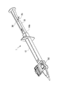
- FIG. 1 shows a schematic configuration of a conventional intraocular lens insertion device 1 (hereinafter also simply referred to as an insertion device 1).
- 1A is a plan view
- FIG. 1B is a side view.
- the insertion instrument 1 is formed in a cylindrical shape having a substantially rectangular cross section, and one side has a large opening (hereinafter, the side having the large opening is referred to as a rear end part 10b), and the insertion cylinder is narrowed to another one side end.
- the nozzle main body 10 as an instrument main body provided with the nozzle part 15 as a part and the front-end
- the direction from the front end portion 10a to the rear end portion 10b of the nozzle body 10 or the opposite direction is the front-rear direction
- the vertical direction to the paper surface in FIG. 1A is the vertical direction
- the paper surface in FIG. The vertical direction is the left-right direction.
- a stage portion 12 is provided as a storage portion for setting the intraocular lens 2.
- the stage portion 12 is configured such that the upper side of the nozzle body 10 (the front side perpendicular to the paper surface in FIG. 1A) is opened by opening the stage lid portion 13.
- a positioning member 50 is attached to the stage portion 12 from the lower side of the nozzle body 10 (the back side perpendicular to the paper surface in FIG. 1A). By this positioning member 50, the intraocular lens 2 is stably held in the stage portion 12 before use (during transportation).
- the intraocular lens 2 is set on the stage unit 12 in a state where the stage lid unit 13 is opened and the positioning member 50 is attached to the stage unit 12 at the time of manufacture. Then, after the stage lid 13 is closed, it is shipped and sold. Further, during use, the user removes the positioning member 50 while keeping the stage lid 13 closed, and then pushes the plunger 30 into the distal end side of the nozzle body 10. Thus, the intraocular lens 2 is pressed by the plunger 30, and the intraocular lens 2 is pushed out from the distal end portion 10a.
- the nozzle body 10, the plunger 30, and the positioning member 50 in the insertion instrument 1 are formed of a resin material such as polypropylene. Polypropylene is a material with a proven track record in medical equipment and high reliability such as chemical resistance.
- FIG. 2 is a diagram showing a schematic configuration of the intraocular lens 2.
- 2A is a plan view and FIG. 2B is a side view.
- the intraocular lens 2 is formed of a lens body 2a having a predetermined refractive power, and two beard-shaped support portions 2b, 2b that are provided on the lens body 2a and hold the lens body 2a in the eyeball. ing.
- the support portions 2b and 2b correspond to lens holding portions in this embodiment.
- the lens body 2a is made of a flexible resin material.
- FIG. 3 shows a plan view of the nozzle body 10.
- the intraocular lens 2 is set on the stage unit 12. In this state, the intraocular lens 2 is pushed out from the distal end portion 10a by being pressed by the plunger 30.
- a through hole 10 c whose cross-sectional shape changes according to a change in the outer shape of the nozzle body 10 is provided in the nozzle body 10.
- the intraocular lens 2 is pushed out, the intraocular lens 2 is deformed in accordance with a change in the cross-sectional shape of the through hole 10c in the nozzle body 10 and easily enters an incision formed in the patient's eyeball. It will be extruded after being transformed into.
- a stage groove 12 a having a width slightly larger than the diameter of the lens body 2 a of the intraocular lens 2 is formed in the stage portion 12.
- the dimension in the front-rear direction of the stage groove 12 a is set to be larger than the maximum width dimension including the support portions 2 b and 2 b extending on both sides of the intraocular lens 2.
- a set surface 12b is formed by the bottom surface of the stage groove 12a.
- the vertical position of the set surface 12b (the position perpendicular to the paper surface of FIG. 3) is set higher than the height position of the bottom surface of the through hole 10c of the nozzle body 10 (the front side perpendicular to the paper surface of FIG. 3).
- the set surface 12b and the bottom surface of the through hole 10c are connected by a bottom slope 10d.
- the stage portion 12 and the stage lid portion 13 are integrally formed.
- the stage lid portion 13 has the same size in the front-rear direction as the stage portion 12.
- the stage lid portion 13 is connected by a thin plate-like connecting portion 14 formed by extending the side surface of the stage portion 12 to the stage lid portion 13 side.
- the connecting portion 14 is formed to be bendable at the center portion, and the stage lid portion 13 can be closed by overlapping the stage portion 12 from above by bending the connecting portion 14.
- ribs 13 a and 13 b are provided on the surface facing the set surface 12 b when the lid is closed in order to reinforce the stage lid 13 and stabilize the position of the intraocular lens 2.
- a guide protrusion 13 c is provided as a guide on the upper side of the plunger 30.
- FIG. 4 shows a schematic configuration of the positioning member 50.
- 4A shows a plan view
- FIG. 4B shows a side view.
- the positioning member 50 is configured as a separate body from the nozzle main body 10, and has a structure in which a pair of side wall portions 51, 51 are connected by a connecting portion 52. At the lower ends of the respective side wall portions 51, holding portions 53, 53 extending outward and extending are formed.
- first mounting portions 54 and 54 are formed on the upper end portions of the respective side wall portions 51 and 51 so that the shape seen from above is an arc shape and protrudes upward.
- first positioning portions 55, 55 are formed to protrude from the outer peripheral side of the upper end surface of the first placement portion 54. The distance between the inner diameters of the first positioning portion 55 is set to be slightly larger than the diameter dimension of the lens body 2 a of the intraocular lens 1.
- a pair of second placement portions 56 and 56 are formed at both ends of the connecting portion 52 in the front-rear direction, and the shape seen from above is a rectangular shape and protrudes upward.
- the height of the upper surface of the second placement unit 56 is equal to the height of the upper surface of the first placement unit 54.
- second positioning portions 57 and 57 are formed on the outer surface of the second placement portions 56 and 56 so as to further protrude upward over the entire left and right direction of the second placement portion 56. .
- the separation between the insides of the second positioning portions 57 is set to be slightly larger than the diameter of the lens body 2a of the intraocular lens 2.
- locking claws 58 and 58 that slightly protrude in the front-rear direction are formed on the upper end portion of the second placement portion 56 over the entire left-right direction.
- the positioning member 50 is assembled from below the set surface 12b of the nozzle body 10.
- the set surface 12b of the nozzle body 10 is formed with a set surface through hole 12c that penetrates the set surface 12b in the thickness direction.
- the outer shape of the set surface through-hole 12c is a substantially similar shape that is slightly larger than the shape of the first placement portion 54 and the second placement portion 56 of the positioning member 50 as viewed from above.
- the positioning member 50 is assembled from the lower side of the nozzle body 10, and the first placement portions 54 and 54 and the second placement portions 56 and 56 are fixed in a state of protruding from the set surface 12b.
- the bottom surface of the outer peripheral portion of the lens body 2a is placed on the upper surfaces of the first placement portions 54 and 54 and the second placement portions 56 and 56.
- the position of the lens body 2 a is restricted with respect to the horizontal direction by the first positioning portions 55 and 55 and the second positioning portions 57 and 57.
- FIG. 5 shows a schematic configuration of the plunger 30.
- the plunger 30 has a length in the front-rear direction that is slightly larger than the nozzle body 10. And it forms from the action part 31 of the front end side based on a column shape, and the insertion part 32 of the rear end side based on a rectangular rod shape. And the action part 31 is comprised including the cylindrical part 31a made into the column shape, and the thin plate-shaped flat part 31b extended in the left-right direction of the cylindrical part 31a.
- a notch 31 c is formed at the tip of the action part 31.
- the notch 31 c is formed in a groove shape that opens upward in the action portion 31 and penetrates in the left-right direction.
- the groove wall on the distal end side of the cutout portion 31 c is formed with an inclined surface that goes upward as it goes to the distal end side of the action portion 31.
- the insertion part 32 has a substantially H-shaped cross section as a whole, and the horizontal and vertical dimensions thereof are set slightly smaller than the through hole 10c of the nozzle body 10.
- a disc-shaped pressing plate portion 33 is formed at the rear end of the insertion portion 32 so as to spread in the vertical and horizontal directions.
- a claw portion 32 a that protrudes toward the upper side of the insertion portion 32 and can be moved up and down by the elasticity of the material of the plunger 30 is formed at the tip side of the insertion portion 32 in the front-rear direction center.
- the locking hole 10 e shown in FIG. 3 provided in the thickness direction on the upper surface of the nozzle body 10 and the claw portion 32 a engage with each other.
- the relative position between the nozzle body 10 and the plunger 30 in the state is determined.
- the claw portion 32a and the locking hole 10e are formed at the positions where the tip of the action portion 31 is located behind the lens body 2a of the intraocular lens 2 set on the stage portion 12 in the engaged state. It is set so that the notch 31c can support the support part 2b on the rear side of 2a from below.
- the plunger 30 is inserted into the nozzle body 10 and disposed at the initial position. Further, as described above, the positioning member 50 is attached to the nozzle body 10 from below the set surface 12b. Thereby, the 1st mounting part 54 and the 2nd mounting part 56 of the positioning member 50 are hold
- the lens body 2a of the intraocular lens 2 is placed and positioned on the upper surfaces of the first placement part 54 and the second placement part 56 in a state where the support parts 2b and 2b are oriented in the front-rear direction of the nozzle body 10.
- the central portion of the intraocular lens 2 is supported in an unloaded state.
- the support portion 2 b of the intraocular lens 2 is supported by the groove portion 55 a provided in the first positioning portion 55 and the bottom surface of the notch portion 31 c of the plunger 30.
- the positioning member 50 When inserting the intraocular lens 2 into the eyeball using the insertion instrument 1, first, the positioning member 50 is removed from the nozzle body 10. Thereby, the 1st mounting part 54 and the 2nd mounting part 56 which were supporting the lens main body 2a of the intraocular lens 2 retreat from the set surface 12b, and the intraocular lens 2 can move on the set surface 12b. Placed.
- the distal end portion 10a of the nozzle portion 15 of the nozzle body 10 is inserted into the incision provided in the eye tissue.
- the distal end portion 10a has an oblique opening shape, it can be easily inserted into the incision.
- the press board part 33 of the plunger 30 is pushed in the front end side of the nozzle main body 10 in the state. Thereby, the front-end
- the tip of the nozzle body 10 There is a need to further reduce the size in the vicinity of 10a and reduce the diameter of the incision.
- the intraocular lens 2 is pressed by the plunger 30 and moved forward in the nozzle body 10
- the collapse rate of the intraocular lens 2 becomes higher, so that the intraocular lens 2 is removed from the distal end portion 10 a of the nozzle body 10.
- the plunger 30 protrudes excessively from the distal end portion 10a of the nozzle body 10. .
- the plunger 30 is provided with resistance increasing means for increasing the pushing resistance of the plunger 30 after the intraocular lens 2 jumps out of the distal end portion 10a.
- FIG. 6 shows a perspective view of the insertion instrument 1 in the present embodiment.
- a blade portion 35 formed by integral molding with the plunger 30 is provided on the side surface of the insertion portion 32 of the plunger 30.
- the blade portion 35 can be elastically deformed by utilizing the elasticity of the material of the plunger 30.
- the blade portion 35 is formed by extending the side surface of the insertion portion 32 on the rear side of the blade portion 35 in the insertion portion 32 in the lateral direction, and the angle of the coupling portion with the side surface of the insertion portion 32 is 90. It has an acute angle of less than 1 degree.
- the blade portion 35 is positioned behind the rear end portion 10b of the nozzle body 10 and is in contact with the nozzle body 10 in a state (initial state) before the insertion operation of the intraocular lens 2 is performed. Absent. In the operation of inserting the intraocular lens 2 into the eyeball, the blade part 35 is inserted into the nozzle body before and after the intraocular lens 2 is released from the tip 10a of the nozzle body 10 (immediately before, at the time of release, or after the release). 10 abuts against the rear end 10b. In this state, the tip of the plunger 30 does not protrude from the tip 10a. When the plunger 30 is further pushed in from this state, the push-in resistance of the plunger 30 increases sharply due to the deformation of the blade portion 35. *
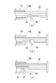
- FIG. 7 shows details of the action of the blade part 35 before and after the intraocular lens 2 is released from the tip part 10a of the nozzle body 10 in the operation of inserting the intraocular lens 2 into the eyeball.
- FIG. 7A shows a state in which the plunger 30 is pushed in by the user, but the blade portion 35 has not reached the rear end portion 10b.
- FIG. 7B shows a state in which the blade portion 35 is in contact with the side surface of the rear end portion 10b, and the plunger 30 is pushed in, whereby the blade portion 35 is deformed and its tilt angle is increased.
- FIG. 7C shows a state in which the plunger 30 is further pushed in after the deformation of the blade portion 35 is finished, and the blade portion 35 is sliding while contacting the inner wall of the through hole 10c.
- the state of FIG. 7A is a state before the intraocular lens 2 is released from the distal end portion 10a, and the pushing resistance of the plunger 30 increases due to the deformation of the intraocular lens 2.
- the part 35 does not contribute to the indentation resistance.
- the state of FIG. 7B is just before and after the time when the intraocular lens 2 is released from the distal end portion 10a. At this point, the pushing resistance caused by the intraocular lens 2 itself has weakened or disappeared. In this state, when the user pushes the plunger 30 into the nozzle body 10, the plunger 30 enters the nozzle body 10 while deforming the blade portion 35, so that the pushing resistance increases sharply. .
- the pushing resistance of the plunger 30 once increases sharply before and after the intraocular lens 2 is released into the eyeball from the tip portion 10a, and the intraocular lens 2 is moved into the eyeball from the tip portion 10a.
- the push-in resistance of the plunger 30 can be sufficiently increased at the time when it is released or after. And although it decreases a little after that, the state where pushing resistance is still high can be continued.
- the distal end of the plunger 30 protrudes vigorously from the distal end portion 10a, and inconveniences such as damaging the eyeball can be suppressed.
- the blade portion 35 as the resistance increasing means extends from the plunger 30 on the rear side of the blade portion 35, and the angle between the blade portion 35 and the insertion portion 32 of the plunger 30 is 90 degrees.
- FIG. 8 shows a variation of the structure of the blade portion.
- FIG. 8A shows the structure described in the first embodiment
- FIG. 8B shows a structure in which the blade portion 35 extends from the front side of the blade portion 35 in the insertion portion 32 of the plunger 30.
- the angle between the insertion portion 32 and the insertion portion 32 is an obtuse angle of 90 degrees or more.
- the blade portion 16 is provided on the nozzle body 10 side, and the pushing resistance of the plunger 30 is increased by contacting the amplifying portion 33 whose width increases in the insertion portion 32 of the plunger 30. It doesn't matter if you do.
- the example in which the blade portion 35 is formed integrally with the plunger 30 or the nozzle body 10 has been described. However, this is formed as a separate part, and bonding, screwing, and elasticity of the resin are used. You may fix to the plunger 30 or the nozzle body 10 by the fixed method etc. which were carried out. Further, the material of the blade portion 35 is not necessarily the same as that of the plunger 30 and the nozzle body 10 (for example, polypropylene), and may be a metal such as phosphor bronze, copper, or SUS.
- a raised portion 31e is provided on the rear side from a predetermined position of the action portion 31 of the plunger 30 so as to rise, and the through hole 10c has a structure.
- a contact portion 10g is provided on the front side of the raised portion 31e of the plunger 30 so as not to contact the action portion 31 of the plunger 30 but to contact the raised portion 31e.
- the contact portion 10g and the raised portion 31e of the plunger 30 constitute second resistance increasing means.
- FIG. 9 illustrates the plunger 30 in the present embodiment.
- the action part 31 of the plunger 30 is provided with a raised part 31e whose height in the upward direction is increased midway.
- a tapered slope 31f is provided on the leading end side of the raised portion 31e, and the raised height gradually increases as going backward.
- FIG. 10 shows a partial cross-sectional view of the nozzle body 10 in the present embodiment.
- a contact portion 10g having a wedge-shaped cross section is formed from the ceiling surface of the through hole 10c toward the lower side in the rear portion of the stage portion 12 of the ceiling surface of the through hole 10c. Yes.
- the tip height of the contact portion 10g is set so as not to contact the front side of the inclined surface 31f in the action portion 31 of the plunger 30, but to contact the raised portion 31e behind the inclined surface 31f.
- FIG. 11 explains the operation of the second resistance increasing means in the present embodiment.
- FIG. 11A shows a state before the raised portion 31e and the contact portion 10g come into contact with each other in a state where the user pushes the plunger 30.
- FIG. 11B shows a state in which the plunger 30 has moved further forward and the contact portion 10g has come into contact with the slope 31f of the raised portion 31e.
- FIG. 11C shows a state in which the plunger 30 further moves forward, and the contact portion 10g completely slides on the raised portion 31f while sliding.
- the slope 31f of the raised portion 31e and the contact portion 10g are positioned at positions such that the intraocular lens 2 starts to contact before the intraocular lens 2 is discharged from the tip portion 10a of the nozzle body 10. Is set. Thereby, the pushing resistance of the plunger 30 gradually increases from before the intraocular lens 2 is discharged into the eyeball, and then the state where the pushing resistance is high can be continued. As a result, when the user releases the intraocular lens 2 into the eyeball, the distal end of the plunger 30 can be gradually advanced, and the intraocular lens 2 can be prevented from jumping out from the distal end portion 10a.
- a raised portion 31e and a contact portion 10g are provided. Therefore, by these combinations, the pushing resistance of the plunger 30 before and after the intraocular lens 2 is ejected from the distal end portion 10a can be set with a higher degree of freedom.
- FIG. 12 shows the pushing resistance of the plunger 30 when the blade portion 35 which is the resistance increasing means in the present embodiment, the rising portion 31e and the contact portion 10g which are the second resistance increasing means are acted.
- the broken line indicates the pushing resistance in the conventional example without the blade portion 35, the raised portion 31e, and the contact portion 10g.
- D1 indicates the plunger push-in amount at which the intraocular lens 2 starts to come out from the tip portion 10a
- D2 indicates the plunger push-in amount when the intraocular lens 2 is released from the tip portion 10a.
- the amount of deformation of the intraocular lens 2 increases immediately before the intraocular lens 2 starts to come out from the distal end portion 10a.
- the resistance decreases.
- the intraocular lens 2 protrudes from the distal end portion 10a, and the plunger 30 protrudes vigorously from the distal end portion 10a.
- the plunger push-in resistance in this embodiment starts to increase sharply when the plunger push-in amount exceeds D1, and reaches a peak when the plunger push-in amount becomes D2. After that, the plunger pushing resistance slightly decreases, but changes so as to further increase.
- the plunger pushing resistance starts to increase sharply when the plunger pushing amount exceeds D1, which is an effect due to the contact between the rising portion 31e and the contact portion 10g.
- the plunger pushing resistance reaches a peak when the plunger pushing amount becomes D2, and is slightly reduced because of the effect that the blade portion 35 is deformed at that timing and then the sliding operation is started.
- the intraocular lens 2 is separated from the distal end portion 10a by combining the blade portion 35, the raised portion 31e, and the contact portion 10g, in other words, by combining the resistance increasing means and the second resistance increasing means.
- the plunger push-in resistance was sharply increased from before the release, and the plunger push-in resistance peaked at the timing when the intraocular lens 2 was released from the distal end portion 10a.
- the peak of the plunger push-in resistance is given at the timing when the intraocular lens 2 is released from the distal end portion 10a, but the present invention is not limited to this. The peak may be set slightly after the timing when the intraocular lens 2 is released from the distal end portion 10a.
- the raised portion 31e has a certain height behind the slope 31f.
- the plunger push-in resistance caused by the raised portion may be controlled by appropriately changing the height of the raised portion.
- FIG. 13 shows a variation example of the shape of the raised portion.
- FIG. 13A shows the rising portion 31e in the above embodiment.
- the height of the rising portion once reaches the peak behind the slope 31f, and then reaches a constant height after decreasing.
- the second resistance increasing means like the resistance increasing means, the pushing resistance of the plunger 30 is once increased sharply before and after the intraocular lens 2 is ejected from the distal end portion 10a, and then the pushing resistance is slightly increased. Control such as decreasing and continuing is possible.
- the user can move the plunger 30 when the intraocular lens 2 is released from the distal end portion 10a or after it is released. It is also possible to give a resistance accompanied by a click feeling when pushing further.
- a blade portion was used as the resistance increasing means, and a combination of the raised portion and the contact portion was used as the second resistance increasing means.
- the present invention is not limited to this combination.
- a resistance increasing means a raised portion is formed in a protruding shape as shown in FIG. 13 (b) at the insertion portion of the plunger, and a contact portion is also formed in a protruding shape on the inner wall of the nozzle body. May be used. According to this mechanism, the peak of the plunger push-in resistance can be generated at the timing when the protruding raised portion and the protruding contact portion come into contact with each other. Moreover, it is also possible to increase the indentation resistance after the peak by raising the back of the protruding raised portion of the plunger at a certain height.
- the resistance increasing means in the present invention is not limited to the one using elastic force or frictional resistance as described above.
- an oil damper is operated, an adhesive protrusion is brought into contact with the nozzle body, etc., thereby increasing resistance by using the viscosity or adhesive force of the substance. May be configured.
- a so-called preset system including a preset type insertion instrument in which an intraocular lens is loaded in advance on an intraocular lens insertion instrument
- the present invention is not limited to this, so that the intraocular lens insertion device and the intraocular lens are stored separately, and the so-called intraocular lens is loaded immediately before insertion into the eyeball. It can also be applied to a separate inserter.
- the intraocular lens to be inserted has been described as an example using a so-called three-piece type in which the lens body (optical part) and the support part are made of different materials, but the lens body (optical part)
- the present invention can also be applied to an insertion instrument for inserting a so-called one-piece intraocular lens in which the support part is integrally molded.
- the example of the material of the insertion device 1 is polypropylene, but the material of the insertion device 1 is not limited to this.
- the present invention can also be applied to an insertion device made of other materials.
Landscapes
- Health & Medical Sciences (AREA)
- Ophthalmology & Optometry (AREA)
- Cardiology (AREA)
- Oral & Maxillofacial Surgery (AREA)
- Transplantation (AREA)
- Engineering & Computer Science (AREA)
- Biomedical Technology (AREA)
- Heart & Thoracic Surgery (AREA)
- Vascular Medicine (AREA)
- Life Sciences & Earth Sciences (AREA)
- Animal Behavior & Ethology (AREA)
- General Health & Medical Sciences (AREA)
- Public Health (AREA)
- Veterinary Medicine (AREA)
- Prostheses (AREA)
Abstract
眼内レンズを挿入器具から押し出した後に、プランジャが挿入筒部から勢いよく突出することを抑制し、眼内レンズの挿入動作をより円滑化できる技術を提供する。眼球組織に形成された切開創口より器具本体の挿入筒部を眼球内に挿入し、器具本体へプランジャを押し込むことで、挿入された挿入筒部の先端から変形可能な眼内レンズを眼球内に放出させる、眼内レンズの挿入器具についてのものである。そして、挿入筒部の先端から眼内レンズが眼球内に放出される時点またはその後に、器具本体へのプランジャの押し込み抵抗を増加させる抵抗増加手段を備える。
Description
本発明は、眼内レンズを患者の眼球内に挿入するための眼内レンズの挿入器具に関する。
従来から、白内障等の手術においては、眼球における角膜(鞏膜)や水晶体前嚢部分などの眼組織に切開創を設け、この切開創を介して、嚢内の水晶体を摘出、除去し、その後に、水晶体に代替する眼内レンズを、前記切開創より眼内に挿入して嚢内に配置させる処置が行われている。
特に近年においては、眼内レンズを切開創より眼球内に挿入する際に、以下に示すような挿入器具が用いられる場合が多い。すなわち、器具本体の先端部に設けられた挿入筒部の先端開口を切開創を通じて眼球内に挿し入れると共に、眼内レンズを器具本体内で小さく変形せしめた状態で挿入筒部の先端開口から棒状のプランジャによって押し出すことにより、眼内レンズを眼球内に挿入する(例えば、特許文献1~5を参照。)。このような挿入器具を用いることにより、水晶体の摘出除去のために形成した切開創を利用して眼内レンズを簡単に眼球内に挿入できるので、手術を簡略化することができ、手術後の乱視の発生や感染症の発生を抑制することができる。
ところで、上記の眼内レンズの挿入作業においては、手術時の患者の負担を低減するために、切開創の大きさをより小径化することが求められており、挿入器具における挿入筒部の先端については、より小さくすることが求められている。しかしながら、挿入筒部の先端が小型化すると、眼内レンズが通過時により圧縮されるため、押し出し時にプランジャに作用する抵抗がより強くなる傾向がある。その結果、操作者が眼内レンズを挿入器具から押し出す際により強い力によってプランジャを押圧する必要があった。
さらに、眼内レンズが挿入筒部から放出された際には急激に抵抗が減少するため、挿入筒部からプランジャの先端を勢いよく突出させてしまう場合があった。
本発明は、上記の従来技術の問題点に鑑みて案出されたものであり、その目的は、眼内レンズを挿入器具から押し出した後に、プランジャが挿入筒部から勢いよく突出することを抑制し、眼内レンズの挿入動作をより円滑化できる技術を提供することである。
本発明は、眼球組織に形成された切開創口より器具本体の挿入筒部を眼球内に挿入し、器具本体へプランジャを押し込むことで、挿入された挿入筒部の先端から変形可能な眼内レンズを眼球内に放出させる、眼内レンズの挿入器具についてのものである。そして、挿入筒部の先端から眼内レンズが眼球内に放出される時点またはその後に、器具本体へのプランジャの押し込み抵抗を増加させる抵抗増加手段を備えることを最大の特徴とする。
より詳しくは、眼球組織に形成された切開創口に挿入される挿入筒部を有し略筒状に形成された器具本体と、
前記器具本体に一体または別体に設けられ眼内レンズを収納することで前記眼内レンズを前記器具本体の内に配置可能な収納部と、
前記器具本体に押し込まれて前記収納部に収納された前記眼内レンズを先端で押圧することで前記眼内レンズを前記挿入筒部から眼球内に放出するプランジャと、
を備え、
前記切開創口より眼球内に挿入された前記挿入筒部の先端から変形可能な眼内レンズを眼球内に放出することで眼内レンズを眼球内に挿入する眼内レンズの挿入器具であって、
前記挿入筒部の先端から眼内レンズが眼球内に放出される時点またはその後に、前記器具本体への前記プランジャの押し込み抵抗を増加させる抵抗増加手段をさらに備えることを特徴とする。
前記器具本体に一体または別体に設けられ眼内レンズを収納することで前記眼内レンズを前記器具本体の内に配置可能な収納部と、
前記器具本体に押し込まれて前記収納部に収納された前記眼内レンズを先端で押圧することで前記眼内レンズを前記挿入筒部から眼球内に放出するプランジャと、
を備え、
前記切開創口より眼球内に挿入された前記挿入筒部の先端から変形可能な眼内レンズを眼球内に放出することで眼内レンズを眼球内に挿入する眼内レンズの挿入器具であって、
前記挿入筒部の先端から眼内レンズが眼球内に放出される時点またはその後に、前記器具本体への前記プランジャの押し込み抵抗を増加させる抵抗増加手段をさらに備えることを特徴とする。
これによれば、挿入筒部の先端から眼内レンズが眼球内に放出される時点またはその後に、器具本体へのプランジャの押し込み抵抗を増加させることができるので、眼内レンズが挿入筒部の先端から放出された後に、眼内レンズを変形させつつ押し出す抵抗が一気になくなることによって、プランジャが勢いよく器具本体(挿入筒部の先端)から突出することを抑制できる。その結果、眼内レンズの挿入作業をより円滑または安全なものにすることが可能である。なお、この場合、抵抗増加手段は、挿入筒部の先端から眼内レンズが眼球内に放出される時点またはその後に、押し込み抵抗のピークがくるように設定されるとよい。そうすれば、プランジャが勢いよく動いては困るタイミングで、押し込み抵抗を急峻に増加させることができ、より確実に、眼内レンズが挿入筒部の先端から放出された後に、プランジャが勢いよく器具本体(挿入筒部の先端)から突出することを抑制できる。
また、本発明においては、前記抵抗増加手段は、前記プランジャまたは器具本体の一方に設けられた羽根状の部材を有し、前記挿入筒部の先端から眼内レンズが眼球内に放出される前後に、前記羽根状の部材が、前記プランジャまたは器具本体の他方に当接し、該羽根状の部材が変形することにより前記押し込み抵抗を、前記挿入筒部の先端から眼内レンズが眼球内に放出される時点またはその後に増加させることとしてもよい。
そうすれば、プランジャまたは器具本体のいずれか一方に設けられた羽根状の部材がプランジャまたは器具本体の他方に当接開始するタイミングを、眼内レンズが挿入筒部の先端から放出される前後の適切なタイミングに合わせることで、より容易に、眼内レンズが挿入筒部の先端から放出される時点またはその後に、プランジャの押し込み抵抗を増加させることが可能となる。
また、本発明においては、前記プランジャまたは器具本体の一方に設けられた羽根状の部材が、前記プランジャまたは器具本体の他方に当接して変形した後、該羽根状の部材は、プランジャの押し込み動作に伴い、前記プランジャまたは器具本体の他方に対して変形した状態で摺動するようにしてもよい。
ここで、通常、プランジャまたは器具本体の一方に設けられた羽根状の部材が、プランジャまたは器具本体の他方に当接して変形する際にはプランジャの押し込み抵抗は急峻に増加する。そして、その後さらに、その変形した状態を維持しつつ、前記プランジャまたは器具本体の他方に対して変形した状態で摺動することで、仮に羽根状の部材を変形させる力と比較すると弱いとしても、より強い押し込み抵抗を摩擦力により得ることが可能となる。
そうすれば、眼内レンズが挿入筒部の先端から放出される時点またはその後に、プランジャの押し込み抵抗を一旦増加させ、さらにプランジャを押し込んだ際にも強い押し込み抵抗を維持することが可能となる。その結果、より確実に、眼内レンズが挿入筒部の先端から放出された後に、プランジャが納入筒部の先端から勢いよく突出してしまうことを抑制できる。
また、本発明においては、前記プランジャまたは前記器具本体の内壁の一方の一部を盛り上げ、該盛り上げた部分が前記プランジャまたは前記器具本体の内壁の他方に当接することによって前記器具本体への前記プランジャの押し込み抵抗を増加させる第二抵抗増加手段をさらに備えるようにしてもよい。
これによれば、所定の位置よりさらにプランジャを器具本体に押し込んだ際に押し込み抵抗を増加させることができる。そして、これを、前記抵抗増加手段と組み合わせることで、より高い自由度で、眼内レンズが挿入筒部の先端から放出される前後におけるプランジャの押し込み抵抗を制御することができる。
例えば、第二抵抗増加手段によって、眼内レンズが挿入筒部の先端から放出される前からプランジャの押し込み抵抗をある程度増加させておいてもよい。これにより、眼内レンズが挿入筒部から放出される際のプランジャの動きをより精密に制御することができ、眼内レンズの飛出しを抑制することができる。
あるいは、第二抵抗増加手段によって、眼内レンズが挿入筒部の先端から放出される時点またはその後における、プランジャの押し込み抵抗を増加させてもよい。そうすれば、抵抗増加手段と第二抵抗増加手段の協働によって、眼内レンズが挿入筒部から放出される時点またはその後のプランジャ押し込み抵抗をより大きなものにすることができる。
また、本発明においては、前記眼内レンズの挿入器具は、製造工程で予め眼内レンズが前記収納部に収納され、該眼内レンズが収納された状態で流通する、プリセット型挿入器具としてもよい。これによれば、より迅速に、そしてより円滑または安全に、眼内レンズを患者の眼球内に挿入することが可能となる。
なお、上記した本発明の課題を解決する手段については、可能なかぎり組み合わせて用いることができる。
本発明によれば、眼内レンズを挿入器具から押し出した後に、プランジャが挿入筒部から勢いよく突出することを抑制することができ、眼内レンズの挿入動作をより円滑化できる。
以下に、図面を参照して本発明の実施の形態について説明する。
〔実施例1〕
図1には、従来の眼内レンズの挿入器具1(以下、単に、挿入器具1ともいう。)の概略構成を示す。図1(a)は平面図、図1(b)は側面図を示している。挿入器具1は、断面略矩形の筒状に形成されており片側は大きく開口し(以下、大きく開口した側を後端部10bという。)、別の片側端部には細く絞られた挿入筒部としてのノズル部15及び斜めに開口した先端部10aを備える器具本体としてのノズル本体10と、ノズル本体10に挿入され往復運動可能なプランジャ30とを備えている。なお、以下において、ノズル本体10の先端部10aから後端部10bへ向かう方向またはその逆方向を前後方向、図1(a)において紙面に垂直方向を上下方向、図1(b)において紙面に垂直方向を左右方向とする。
図1には、従来の眼内レンズの挿入器具1(以下、単に、挿入器具1ともいう。)の概略構成を示す。図1(a)は平面図、図1(b)は側面図を示している。挿入器具1は、断面略矩形の筒状に形成されており片側は大きく開口し(以下、大きく開口した側を後端部10bという。)、別の片側端部には細く絞られた挿入筒部としてのノズル部15及び斜めに開口した先端部10aを備える器具本体としてのノズル本体10と、ノズル本体10に挿入され往復運動可能なプランジャ30とを備えている。なお、以下において、ノズル本体10の先端部10aから後端部10bへ向かう方向またはその逆方向を前後方向、図1(a)において紙面に垂直方向を上下方向、図1(b)において紙面に垂直方向を左右方向とする。
ノズル本体10の後端部10b付近には、板状に迫り出し、使用者がプランジャ30をノズル本体10の先端側に押し込む際に指を掛けるホールド部11が一体的に設けられている。また、ノズル本体10におけるノズル部15の後端側には、眼内レンズ2をセットする収納部としてのステージ部12が設けられている。このステージ部12は、ステージ蓋部13を開蓋することでノズル本体10の上側(図1(a)における紙面垂直手前側)が開放されるようになっている。また、ステージ部12には、ノズル本体10の下側(図1(a)における紙面垂直奥側)から位置決め部材50が取り付けられている。この位置決め部材50によって、使用前(輸送中)において、ステージ部12内で眼内レンズ2が安定して保持されている。
すなわち、挿入器具1においては、製造時に、ステージ蓋部13が開蓋し位置決め部材50がステージ部12に取り付けられた状態で、眼内レンズ2がステージ部12にセットされる。そして、ステージ蓋部13を閉蓋させた後出荷、販売される。さらに、使用時には使用者がステージ蓋部13を閉蓋したままで位置決め部材50を取り外し、その後プランジャ30をノズル本体10の先端側に押し込む。このことで、プランジャ30によって眼内レンズ2を押圧し、先端部10aより眼内レンズ2を押し出す。なお、挿入器具1におけるノズル本体10、プランジャ30、位置決め部材50はポリプロピレンなどの樹脂の素材で形成される。ポリプロピレンは医療用機器において実績があり、耐薬品性などの信頼性も高い素材である。
図2は、眼内レンズ2の概略構成を示した図である。図2(a)は平面図、図2(b)は側面図を示す。眼内レンズ2は、所定の屈折力を有するレンズ本体2aと、レンズ本体2aに設けられ、レンズ本体2aを眼球内で保持するためのヒゲ状の2本の支持部2b、2bとから形成されている。支持部2b、2bは本実施例においてレンズ保持部に相当する。レンズ本体2aは可撓性の樹脂材料から形成されている。
図3にはノズル本体10の平面図を示す。前述のようにノズル本体10においては、眼内レンズ2はステージ部12にセットされる。そして、その状態でプランジャ30によって押圧されて先端部10aから眼内レンズ2が押し出される。なお、ノズル本体10の内部にはノズル本体10の外形の変化に応じて断面形状が変化する貫通孔10cが設けられている。そして、眼内レンズ2が押し出される際は、眼内レンズ2は、ノズル本体10内の貫通孔10cの断面形状の変化に応じて変形し、患者の眼球に形成された切開創に入り易い形に変形した上で押し出されることになる。
ステージ部12には、眼内レンズ2のレンズ本体2aの径より僅かに大きな幅を有するステージ溝12aが形成されている。ステージ溝12aの前後方向の寸法は、眼内レンズ2の両側に延びる支持部2b、2bを含む最大幅寸法よりも大きく設定されている。また、ステージ溝12aの底面によってセット面12bが形成されている。セット面12bの上下方向位置(図3の紙面に垂直方向の位置)は、ノズル本体10の貫通孔10cの底面の高さ位置よりも上方(図3の紙面に垂直方向手前側)に設定されており、セット面12bと貫通孔10cの底面とは底部斜面10dによって連結されている。
ステージ部12とステージ蓋部13とは一体に形成されている。ステージ蓋部13はステージ部12と同等の前後方向の寸法を有している。ステージ蓋部13は、ステージ部12の側面がステージ蓋部13側に延出して形成された薄板状の連結部14によって連結されている。連結部14は中央部で屈曲可能に形成されており、ステージ蓋部13は、連結部14を屈曲させることでステージ部12に上側から重なり閉蓋することができるようになっている。
ステージ蓋部13において、閉蓋時にセット面12bと対向する面には、ステージ蓋部13を補強し、眼内レンズ2の位置を安定させるためにリブ13a及び13bが設けられている。また、プランジャ30の上側のガイドとして案内突起13cが設けられている。
ステージ部12のセット面12bの下側には、位置決め部材50が取外し可能に設けられている。図4に、位置決め部材50の概略構成を示す。図4(a)は平面図を示し、図4(b)は側面図を示している。位置決め部材50はノズル本体10と別体として構成されており、一対の側壁部51、51が連結部52で連結された構造とされている。それぞれの側壁部51の下端には、外側に向けて延出して広がる保持部53、53が形成されている。
そして、それぞれの側壁部51、51の上端部には、上方から見た形状が円弧形状であり上側に突出した一対の第一載置部54、54が形成されている。さらに、第一載置部54の上端面における外周側には、第一位置決め部55、55が突出して形成されている。第一位置決め部55の内径どうしの距離は、眼内レンズ1のレンズ本体2aの径寸法よりも僅かに大きく設定されている。
また、連結部52の前後方向の両端には、上方から見た形状が矩形状であり上側に突出した一対の第二載置部56、56が形成されている。第二載置部56の上面の高さは、第一載置部54の上面の高さと同等になっている。更に、第二載置部56、56の上面において外側の部分には、第二載置部56の左右方向の全体に亘って上側にさらに突出する第二位置決め部57、57が形成されている。第二位置決め部57内側どうしの離隔は、眼内レンズ2のレンズ本体2aの径寸法よりも僅かに大きく設定されている。加えて、第二載置部56の上端部には左右方向の全体に亘り、前後方向に僅かに突出した係止爪58、58が形成されている。
本実施例では、上記の位置決め部材50が、ノズル本体10のセット面12bの下側から組み付けられる。ノズル本体10のセット面12bには、厚さ方向にセット面12bを貫通するセット面貫通孔12cが形成されている。セット面貫通孔12cの外形は、位置決め部材50の第一載置部54および第二載置部56を上側から見た形状に対し僅かに大きな略相似形状とされている。そして、位置決め部材50がノズル本体10に取り付けられる際には、第一載置部54、54および第二載置部56、56が、セット面12bの下側からセット面貫通孔12cに挿入され、セット面12bの上側に突出する。
その際、第二位置決め部57、57に設けられた係止爪58、58がセット面貫通孔12cを介してセット面12bに突出し、セット面12bの上面に係止される。このことによって、位置決め部材50がノズル本体10の下側から組み付けられ、第一載置部54、54および第二載置部56、56がセット面12bから突出した状態で固定される。そして、眼内レンズ2がセット面12bにセットされる際には、レンズ本体2aの外周部底面が、第一載置部54、54および第二載置部56、56の上面に載置される。また、レンズ本体2aは第一位置決め部55、55及び第二位置決め部57、57によって水平方向に対して位置規制される。
図5にはプランジャ30の概略構成を示す。プランジャ30は、ノズル本体10よりもやや大きな前後方向長さを有している。そして、円柱形状を基本とした先端側の作用部31と、矩形ロッド形状を基本とした後端側の挿通部32とから形成されている。そして、作用部31は、円柱形状とされた円柱部31aと、円柱部31aの左右方向に広がる薄板状の扁平部31bとを含んで構成されている。
作用部31の先端部分には、切欠部31cが形成されている。この切欠部31cは、図5から分かるように、作用部31の上方向に開口し左右方向に貫通する溝状に形成されている。また、図5(b)から分かるように、切欠部31cの先端側の溝壁は作用部31の先端側に行くに連れて上方に向かう傾斜面で形成されている。
一方、挿通部32は、は全体的に概略H字状の断面を有しており、その左右方向および上下方向の寸法は、ノズル本体10の貫通孔10cよりも僅かに小さく設定されている。また、挿通部32の後端には、上下左右方向に広がる円板状の押圧板部33が形成されている。
挿通部32の前後方向の中央より先端側の部分には、挿通部32の上側に向けて突出し、プランジャ30の素材の弾性により上下に移動可能な爪部32aが形成されている。そして、プランジャ30がノズル本体10に挿入された際には、ノズル本体10の上面において厚さ方向に設けられた図3に示す係止孔10eと爪部32aが係合し、このことにより初期状態におけるノズル本体10とプランジャ30との相対位置が決定される。なお、爪部32aと係止孔10eの形成位置は、係合状態において、作用部31の先端が、ステージ部12にセットされた眼内レンズ2のレンズ本体2aの後方に位置し、レンズ本体2aの後方の支持部2bを切欠部31cが下方から支持可能な場所に位置するよう設定されている。
上記のように構成された挿入器具1の使用前においては、プランジャ30がノズル本体10に挿入されて初期位置に配置される。また、位置決め部材50が、前述のように、セット面12bの下方からノズル本体10に取り付けられる。これにより、位置決め部材50の第一載置部54および第二載置部56がセット面12bに突出した状態に保持される。
次に、眼内レンズ2のレンズ本体2aが支持部2b、2bをノズル本体10の前後方向に向けた状態で第一載置部54および第二載置部56の上面に載置され位置決めされる。この状態において、眼内レンズ2は、レンズ本体2aの外周部分が第一載置部54および第二載置部56に接触しているので、中央部分は非負荷状態で支持されている。また、この状態において、眼内レンズ2の支持部2bは、第一位置決め部55に設けられた溝部55a及びプランジャ30の切欠部31cの底面によって支持されている。
挿入器具1を用いて眼内レンズ2を眼球内に挿入する場合には、先ず、位置決め部材50をノズル本体10から取り外す。これにより、眼内レンズ2のレンズ本体2aを支持していた第一載置部54および第二載置部56がセット面12bから後退し、眼内レンズ2がセット面12b上に移動可能に載置される。
続いて、眼組織に設けた切開創に、ノズル本体10のノズル部15における先端部10aを挿入する。ここにおいて、先端部10aは斜めの開口形状を有しているので、切開創への挿入を容易に行なうことができる。そして、切開創にノズル部15を挿入した後に、その状態で、プランジャ30の押圧板部33をノズル本体10の先端側に押し込む。これにより、セット面12aにセットされた眼内レンズ2のレンズ本体2a外周にプランジャ30の作用部31の先端が当接し、プランジャ30によって眼内レンズ2が先端部10aに向けて案内される。
上記で説明したような眼内レンズの挿入器具1を用いて、患者の眼球内に眼内レンズ2を挿入させる手術に関して、近年は、患者の負担を軽減するために、ノズル本体10の先端部10a付近の寸法をより小型化し、切開創の径をより小径で済むようにする要求がある。そうした場合、プランジャ30によって眼内レンズ2が押圧されてノズル本体10内を前方に移動すると、眼内レンズ2のつぶれ率がより高くなるので、眼内レンズ2がノズル本体10の先端部10aから押し出される際には、より大きな押し込み力でプランジャを押し込む必要がある。
そして、眼内レンズ2が先端部10aから放出された後、プランジャ30の押出し抵抗が急激に減少するため、プランジャ30がノズル本体10の先端部10aから勢い余って突出してしまう危険性があった。なお、眼内レンズ2が先端部10aから放出された後に、プランジャ30を先端部10aからゆっくりと突出させ、プランジャ30の先端で眼球内の眼内レンズ2の位置を微調整する必要があるので、機構的にプランジャ30が先端部10aから突出不可能としてしまうことは避ける必要がある。
これに対し、本実施例では、プランジャ30に、眼内レンズ2が先端部10aから飛び出した後、プランジャ30の押出し抵抗を増加させる抵抗増加手段を備えることとした。
図6には、本実施例における挿入器具1についての斜視図を示す。図6において、上記した従来例との相違点についてのみ説明し、従来例と同等の構成については従来例を同じ符号を付して説明を省略する。本実施例においてはプランジャ30の挿通部32の側面にプランジャ30との一体成型により形成された羽根部35が設けられている。この羽根部35は、プランジャ30の素材の弾性を利用して弾性変形が可能である。また、羽根部35は挿通部32における羽根部35より後側における挿通部32の側面が横方向に延設されることで形成されており、挿通部32の側面との結合部の角度は90度以下の鋭角となっている。
また、羽根部35は、眼内レンズ2の挿入動作を行なう前の状態(初期状態)では、ノズル本体10の後端部10bよりも後方に位置しており、ノズル本体10とは接触していない。そして、眼内レンズ2の眼球への挿入動作において、眼内レンズ2がノズル本体10の先端部10aから放出される前後(放出直前、放出時点または放出後)に、この羽根部35がノズル本体10の後端部10bに当接する。この状態ではプランジャ30の先端は先端部10aから突出していない。この状態からさらにプランジャ30が押し込まれた場合には羽根部35が変形することでプランジャ30の押し込み抵抗が急峻に増加する。
図7には、眼内レンズ2の眼球への挿入動作において、眼内レンズ2がノズル本体10の先端部10aから放出される前後の羽根部35の作用の詳細について示す。図7(a)は、プランジャ30が使用者によって押し込まれているが、羽根部35が後端部10bに達していない状態を示す。図7(b)は、羽根部35が後端部10bの側面に当接し、さらにプランジャ30が押し込まれることにより、羽根部35が変形しその倒れ角が増加している状態を示す。さらに図7(c)は、羽根部35の変形が終了した状態でさらにプランジャ30が押し込まれ、羽根部35が貫通穴10cの内壁に接しつつ摺動している状態を示す。
図7(a)の状態は、眼内レンズ2が先端部10aから放出される前の状態であり、眼内レンズ2の変形に起因してプランジャ30の押し込み抵抗が増加しているが、羽根部35は押し込み抵抗には寄与していない。次に、図7(b)の状態は、まさに眼内レンズ2が先端部10aから放出される時点の前後である。この時点で、眼内レンズ2自体に起因する押し込み抵抗は弱まりまたは消滅している。この状態においては、使用者がプランジャ30をノズル本体10内に押し込むに当たり、羽根部35を変形させながらプランジャ30がノズル本体10内に進入していくこととなるので、押し込み抵抗が急峻に増大する。そして、図7(c)の状態では、眼内レンズ2は先端部10aから完全に放出されている。この時点で、眼内レンズ2自体に起因する押し込み抵抗は消滅している。羽根部35が基の状態に戻ろうとする復元力によって貫通穴10cの内壁に強く当接した状態でプランジャ30がノズル本体10内に進入していくので、羽根部35に起因するプランジャ30の押し込み抵抗は、図7(b)の状態と比較すると小さくなるものの、図7(a)の状態よりは大きくなる。
このような羽根部35の作用により、眼内レンズ2が先端部10aより眼球内に放出された前後にプランジャ30の押し込み抵抗が一旦急峻に増加し、眼内レンズ2が先端部10aより眼球内に放出された時点またはその後にプランジャ30の押し込み抵抗を充分に増加させることができる。そして、その後、若干減少するものの押し込み抵抗がなお高い状態を継続させることができる。その結果、使用者が眼内レンズ2を眼球内に放出させた後に、プランジャ30の先端が先端部10aから勢い良く突出し、眼球を傷付けるなどの不都合を抑制することができる。
なお、上記の実施例1においては抵抗増加手段としての羽根部35は、羽根部35の後側におけるプランジャ30から延設され羽根部35とプランジャ30の挿通部32との間の角度は90度未満の鋭角となっている例について示した。しかしながら、羽根部35の構造はこれに限定されない。図8には羽根部の構造のバリエーションを示す。図8(a)は上記の実施例1で説明した構造、図8(b)は、羽根部35がプランジャ30の挿通部32における羽根部35の前側から延設され羽根部35とプランジャ30の挿通部32との間の角度は90度以上の鈍角となっている例である。また、図8(c)に示すように、羽根部16はノズル本体10側に設け、プランジャ30の挿通部32において幅が増加する増幅部33に当接することでプランジャ30の押し込み抵抗が増加するようにしても構わない。
さらに、上記の実施例1においては羽根部35がプランジャ30またはノズル本体10と一体成型で形成された例について説明したが、これを別部品で形成して接着、ねじ止め、樹脂の弾性を利用した固定法などでプランジャ30またはノズル本体10に固定しても構わない。さらに、羽根部35の材質はプランジャ30、ノズル本体10と同じ(例えば、ポリプロピレン)である必要はなく、例えばりん青銅、銅、SUSなどの金属であってもよい。
〔実施例2〕
次に、本発明の実施例2について説明する。本実施例においては、抵抗増加手段としての羽根部35に加えて、プランジャ30の作用部31の所定位置より後側に盛上がり部31eを設けて盛り上がるような構造とし、また、貫通穴10cにはプランジャ30の盛上がり部31eより前側においてはプランジャ30の作用部31に接触せず、盛上がり部31eには接触するような接触部10gを設けた例について説明する。なお、本実施例において接触部10g及び、プランジャ30の盛上がり部31eは第二抵抗増加手段を構成する。
次に、本発明の実施例2について説明する。本実施例においては、抵抗増加手段としての羽根部35に加えて、プランジャ30の作用部31の所定位置より後側に盛上がり部31eを設けて盛り上がるような構造とし、また、貫通穴10cにはプランジャ30の盛上がり部31eより前側においてはプランジャ30の作用部31に接触せず、盛上がり部31eには接触するような接触部10gを設けた例について説明する。なお、本実施例において接触部10g及び、プランジャ30の盛上がり部31eは第二抵抗増加手段を構成する。
図9には、本実施例におけるプランジャ30について説明する。図9においては、上述した実施例1に係るプランジャ30と同等の構成については従来例と同じ符号を用いて説明を省略する。図9において、プランジャ30の作用部31には、途中より上方向の高さが増加した盛上がり部31eが設けられている。この例では、盛上がり部31eの先端側はテーパ状の斜面31fが設けられており、盛上がり高さは後方へいくにつれて徐々に高くなるようになっている。
図10には、本実施例におけるノズル本体10についての部分断面図を示す。本実施例のノズル本体10においては、貫通孔10cの天井面の、ステージ部12の後側の部分に断面楔状の接触部10gが、貫通穴10cの天井面から下側に向けて形成されている。そして接触部10gの先端高さは、プランジャ30の作用部31における斜面31fの前側には接触しないが、斜面31fより後方の盛上がり部31eには接触するように設定されている。
図11には、本実施例における第二抵抗増加手段の作用について説明する。図11(a)は、使用者がプランジャ30を押し込んでいる状態において、盛り上がり部31eと接触部10gが接触する前の状態を示す。図11(b)は、プランジャ30がより前方に移動し、接触部10gが盛り上がり部31eの斜面31fとの接触が生じた状態を示す。図11(c)は、さらにプランジャ30が前方に移動し、接触部10gが完全に盛り上がり部31fに乗り上げつつ両者が摺動している状態を示す。
なお、本実施例において、盛り上がり部31eの斜面31fと、接触部10gとは、眼内レンズ2が、ノズル本体10の先端部10aから排出される手前で接触を開始するように、各々の位置が設定されている。これにより、眼内レンズ2が眼球内に排出された手前から徐々にプランジャ30の押し込み抵抗が増加し、その後、押し込み抵抗が高い状態を継続させることができる。その結果、使用者が眼内レンズ2を眼球内に放出させる際に、プランジャ30の先端を徐々に前進させることができ、眼内レンズ2が先端部10aより勢い良く飛び出すことを抑制できる。
また、本実施例では、実施例1で説明した羽根部35に加えて、盛り上がり部31eと接触部10gとを設けている。従って、これらの組合せにより、眼内レンズ2が先端部10aから排出される前後のプランジャ30の押し込み抵抗をより高い自由度で設定することができる。
図12には、本実施例における抵抗増加手段である羽根部35と、第二抵抗増加手段である盛上がり部31e及び接触部10gとを作用させた場合の、プランジャ30の押し込み抵抗について示す。一方、破線で示すのは羽根部35、盛上がり部31e、接触部10gがない従来例における押し込み抵抗である。また、D1は、眼内レンズ2が先端部10aより出始めるプランジャ押し込み量、D2は、眼内レンズ2が先端部10aより放出された際のプランジャ押し込み量を示す。
図12を見て分かるように、従来例によれば、眼内レンズ2が先端部10aから出始める直前あたりで、眼内レンズ2の変形量が増加するので、プランジャ押し込み抵抗は最大となり、眼内レンズ2が先端部10aから出始めると抵抗が低くなる。これにより、眼内レンズ2が先端部10aより飛び出し、さらにプランジャ30が先端部10aより勢いよく突出してしまうという不都合が生じるおそれがあった。
それに対して、本実施例におけるプランジャ押し込み抵抗は、プランジャ押し込み量がD1を超えたあたりから急峻に増加し始め、プランジャ押し込み量がD2となるあたりでピークを迎えている。そして、その後プランジャ押し込み抵抗は若干低下するが、さらに増加するように推移している。ここで、プランジャ押し込み抵抗は、プランジャ押し込み量がD1を超えたあたりから急峻に増加し始めるのは、盛上がり部31eと接触部10gが接触を始めたことによる効果である。また、プランジャ押し込み抵抗が、プランジャ押し込み量がD2となるあたりでピークを迎え、若干低下することは、羽根部35がそのタイミングで変形し、その後摺動動作に移ったことによる効果である。
このように、本実施例においては、羽根部35、盛上がり部31e、接触部10gを組合せ、換言すると抵抗増加手段と第二抵抗増加手段とを組み合わせることにより、眼内レンズ2が先端部10aから放出される手前からプランジャ押し込み抵抗を急峻に増加させ、眼内レンズ2が先端部10aから放出されるタイミングにプランジャ押し込み抵抗のピークを持ってくることができた。
これにより、より確実に、眼内レンズ2が先端部10aから放出された後にプランジャ30が先端部10aから勢いよく突出することを抑制できる。また、同時に、眼内レンズ2の放出時に、眼内レンズ2が先端部10aから飛び出してしまうことを抑制できる。なお、図12のグラフでは、眼内レンズ2が先端部10aから放出されるタイミングにプランジャ押し込み抵抗のピークを持ってきたが、本発明はこれに限定されるものではない。ピークを、眼内レンズ2が先端部10aから放出されるタイミングの若干後に設定しても構わない。そうすることで、眼内レンズ2が先端部10aから放出された後に、プランジャ30が先端部10aから勢いよく突出しかけた際に、押し込み抵抗のピークを合わせ、より確実に、プランジャ30の突出を抑制することが可能となる。
なお、上記の実施例においては、盛り上がり部31eは斜面31fの後方は一定の高さを有するものとした。これに対し、盛り上がり部の高さを適宜変化させて、盛上がり部に起因するプランジャ押し込み抵抗を制御するようにしてもよい。図13には盛り上がり部の形状のバリエーション例を示す。図13(a)は上記の実施例における盛上がり部31eである。図13(b)に示した盛上がり部31gにおいては、斜面31fの後方で一旦盛り上がり部の高さがピークを迎え、その後低下した後に一定高さになるようになっている。こうすれば、第二抵抗増加手段においても、抵抗増加手段と同様、眼内レンズ2が先端部10aから排出される前後にプランジャ30の押し込み抵抗を一旦急峻に増加させ、その後、若干押し込み抵抗を減少させて継続させるなどの制御が可能となる。
また、図12(c)に示すように、等間隔で突起状の盛り上がり部31hを設けることで、眼内レンズ2が先端部10aから放出される時点または放出された後に、使用者がプランジャ30をさらに押し込む際にクリック感を伴う抵抗を与えることも可能である。
なお、本実施例においては、抵抗増加手段として羽根部、第二抵抗増加手段として盛上がり部と接触部の組合せを用いた。しかしながら、本発明はこの組合せに限定されるものではない。例えば、抵抗増加手段として、プランジャの挿通部に盛上がり部を図13(b)に示したような突起状に盛上がらせて形成し、ノズル本体の内壁にやはり突起状に接触部を形成したものを用いてもよい。この機構によれば、突起状の盛上がり部と突起状の接触部とが接触するタイミングで、プランジャ押し込み抵抗のピークを生じさせることができる。また、プランジャの突起状の盛上がり部の後方をある程度の高さで盛り上げておくことで、ピークの後の押し込み抵抗を増加させることも可能である。
また、本発明における抵抗増加手段は、上記のように弾性力や摩擦抵抗を用いたものに限られない。例えば、眼内レンズ2が先端部10aから放出される時点またはその後に、オイルダンパを働かせる、粘着性の突起部をノズル本体に接触させるなど、物質の粘性や粘着力を用いることで抵抗増加手段を構成しても構わない。
なお、上記の各実施例においては眼内レンズの挿入器具に予め眼内レンズが装填されたいわゆるプリセットシステム(プリセット型挿入器具を含む)について説明した。しかしながら、本発明はこれに限定されるものではなく、眼内レンズの挿入器具と眼内レンズを別々に保管しておき、眼球内への挿入作業の直前に眼内レンズを装填するためのいわゆるセパレートインサータについても適用され得る。また同様に、各実施例では、挿入する眼内レンズを、レンズ本体(光学部)と支持部が別の材料で作られるいわゆるスリーピース型を使用する例で説明したが、レンズ本体(光学部)と支持部が一体成型される、いわゆるワンピース型眼内レンズを挿入するための挿入器具にも、本発明を適用することができる。また、上記の実施例では挿入器具1の材質としてポリプロピレンを例にとって説明したが、挿入器具1の材質はこれに限られない。他の材質によって形成された挿入器具にも適用可能である。
1・・・挿入器具
2・・・眼内レンズ
10・・・ノズル本体
10a・・・先端部
10b・・・後端部
10f・・・ガイド部
10g・・・接触部
12・・・ステージ部
12b・・・セット面
13・・・ステージ蓋部
13a・・・リブ
13b・・・リブ
13c・・・案内突起
15・・・挿入筒部
30・・・プランジャ
31・・・作用部
31a・・・円柱部
31b・・・扁平部
31e、31g、31h・・・盛上がり部
31f・・・斜面
35・・・羽根部
50・・・位置決め部材
2・・・眼内レンズ
10・・・ノズル本体
10a・・・先端部
10b・・・後端部
10f・・・ガイド部
10g・・・接触部
12・・・ステージ部
12b・・・セット面
13・・・ステージ蓋部
13a・・・リブ
13b・・・リブ
13c・・・案内突起
15・・・挿入筒部
30・・・プランジャ
31・・・作用部
31a・・・円柱部
31b・・・扁平部
31e、31g、31h・・・盛上がり部
31f・・・斜面
35・・・羽根部
50・・・位置決め部材
Claims (5)
- 眼球組織に形成された切開創口に挿入される挿入筒部を有し略筒状に形成された器具本体と、
前記器具本体に一体または別体に設けられ眼内レンズを収納することで前記眼内レンズを前記器具本体の内に配置可能な収納部と、
前記器具本体に押し込まれて前記収納部に収納された前記眼内レンズを先端で押圧することで前記眼内レンズを前記挿入筒部から眼球内に放出するプランジャと、
を備え、
前記切開創口より眼球内に挿入された前記挿入筒部の先端から変形可能な眼内レンズを眼球内に放出することで眼内レンズを眼球内に挿入する眼内レンズの挿入器具であって、
前記挿入筒部の先端から眼内レンズが眼球内に放出される時点またはその後に、前記器具本体への前記プランジャの押し込み抵抗を増加させる抵抗増加手段をさらに備えることを特徴とする眼内レンズの挿入器具。 - 前記抵抗増加手段は、前記プランジャまたは器具本体の一方に設けられた羽根状の部材を有し、前記挿入筒部の先端から眼内レンズが眼球内に放出される前後に、前記羽根状の部材が、前記プランジャまたは器具本体の他方に当接し、該羽根状の部材が変形することにより前記押し込み抵抗を、前記挿入筒部の先端から眼内レンズが眼球内に放出される時点またはその後に増加させることを特徴とする請求項1に記載の眼内レンズの挿入器具。
- 前記プランジャまたは器具本体の一方に設けられた羽根状の部材が、前記プランジャまたは器具本体の他方に当接して変形した後、該羽根状の部材は、プランジャの押し込み動作に伴い、前記プランジャまたは器具本体の他方に対して変形した状態で摺動することを特徴とする請求項2に記載の眼内レンズの挿入器具。
- 前記プランジャまたは前記器具本体の内壁の一方の一部を盛り上げ、該盛り上げた部分が前記プランジャまたは前記器具本体の内壁の他方に当接することによって前記器具本体への前記プランジャの押し込み抵抗を増加させる第二抵抗増加手段をさらに備えることを特徴とする請求項1から3のいずれか一項に記載の眼内レンズの挿入器具。
- 前記眼内レンズの挿入器具は、製造工程で予め眼内レンズが前記収納部に収納され、該眼内レンズが収納された状態で流通する、プリセット型挿入器具であることを特徴とする請求項1から4のいずれか一項に記載の眼内レンズの挿入器具。
Priority Applications (1)
| Application Number | Priority Date | Filing Date | Title |
|---|---|---|---|
| JP2014504908A JP6099628B2 (ja) | 2012-03-14 | 2013-03-11 | 眼内レンズの挿入器具 |
Applications Claiming Priority (2)
| Application Number | Priority Date | Filing Date | Title |
|---|---|---|---|
| JP2012-057539 | 2012-03-14 | ||
| JP2012057539 | 2012-03-14 |
Publications (1)
| Publication Number | Publication Date |
|---|---|
| WO2013137208A1 true WO2013137208A1 (ja) | 2013-09-19 |
Family
ID=49161115
Family Applications (1)
| Application Number | Title | Priority Date | Filing Date |
|---|---|---|---|
| PCT/JP2013/056689 Ceased WO2013137208A1 (ja) | 2012-03-14 | 2013-03-11 | 眼内レンズの挿入器具 |
Country Status (2)
| Country | Link |
|---|---|
| JP (1) | JP6099628B2 (ja) |
| WO (1) | WO2013137208A1 (ja) |
Cited By (10)
| Publication number | Priority date | Publication date | Assignee | Title |
|---|---|---|---|---|
| WO2015076308A1 (ja) * | 2013-11-19 | 2015-05-28 | 興和株式会社 | 眼内レンズの挿入器具 |
| JP2016083364A (ja) * | 2014-10-22 | 2016-05-19 | 参天製薬株式会社 | 眼内レンズ用インジェクタ |
| US9463089B2 (en) | 2012-05-21 | 2016-10-11 | Novartis Ag | Plunger system for intraocular lens surgery |
| JP2017000445A (ja) * | 2015-06-10 | 2017-01-05 | 興和株式会社 | 眼内レンズ挿入器具 |
| WO2017104690A1 (ja) | 2015-12-15 | 2017-06-22 | 参天製薬株式会社 | レンズホルダ及び眼内レンズ用インジェクタ |
| US9757536B2 (en) | 2012-07-17 | 2017-09-12 | Novartis Ag | Soft tip cannula |
| US10568735B2 (en) | 2017-01-13 | 2020-02-25 | Alcon Inc. | Intraocular lens injector |
| US10588780B2 (en) | 2015-03-04 | 2020-03-17 | Alcon Inc. | Intraocular lens injector |
| US11000367B2 (en) | 2017-01-13 | 2021-05-11 | Alcon Inc. | Intraocular lens injector |
| JP2023128728A (ja) * | 2022-03-04 | 2023-09-14 | 株式会社ニデック | 眼内レンズ挿入器具 |
Families Citing this family (2)
| Publication number | Priority date | Publication date | Assignee | Title |
|---|---|---|---|---|
| RU2648229C1 (ru) | 2013-11-14 | 2018-03-22 | Эквисис, Инк. | Устройство для введения интраокулярного шунта |
| BR112020018242A2 (pt) * | 2018-03-09 | 2020-12-29 | Aquesys, Inc. | Insersor de shunt intraocular |
Citations (3)
| Publication number | Priority date | Publication date | Assignee | Title |
|---|---|---|---|---|
| WO2007097221A1 (ja) * | 2006-02-22 | 2007-08-30 | Hoya Corporation | 眼内レンズ挿入器具 |
| WO2007098622A1 (en) * | 2006-02-28 | 2007-09-07 | Sdi Surgical Device International Gmbh | Spring-biased injector for an intraocular lens |
| JP2009160151A (ja) * | 2007-12-28 | 2009-07-23 | Menicon Co Ltd | 眼内レンズの挿入器具 |
Family Cites Families (1)
| Publication number | Priority date | Publication date | Assignee | Title |
|---|---|---|---|---|
| JP5209332B2 (ja) * | 2008-02-04 | 2013-06-12 | 株式会社ニデック | 眼内レンズ挿入器具 |
-
2013
- 2013-03-11 WO PCT/JP2013/056689 patent/WO2013137208A1/ja not_active Ceased
- 2013-03-11 JP JP2014504908A patent/JP6099628B2/ja not_active Expired - Fee Related
Patent Citations (3)
| Publication number | Priority date | Publication date | Assignee | Title |
|---|---|---|---|---|
| WO2007097221A1 (ja) * | 2006-02-22 | 2007-08-30 | Hoya Corporation | 眼内レンズ挿入器具 |
| WO2007098622A1 (en) * | 2006-02-28 | 2007-09-07 | Sdi Surgical Device International Gmbh | Spring-biased injector for an intraocular lens |
| JP2009160151A (ja) * | 2007-12-28 | 2009-07-23 | Menicon Co Ltd | 眼内レンズの挿入器具 |
Cited By (13)
| Publication number | Priority date | Publication date | Assignee | Title |
|---|---|---|---|---|
| US9463089B2 (en) | 2012-05-21 | 2016-10-11 | Novartis Ag | Plunger system for intraocular lens surgery |
| US9757536B2 (en) | 2012-07-17 | 2017-09-12 | Novartis Ag | Soft tip cannula |
| WO2015076308A1 (ja) * | 2013-11-19 | 2015-05-28 | 興和株式会社 | 眼内レンズの挿入器具 |
| JPWO2015076308A1 (ja) * | 2013-11-19 | 2017-03-16 | 興和株式会社 | 眼内レンズの挿入器具 |
| US10195019B2 (en) | 2013-11-19 | 2019-02-05 | Kowa Company, Ltd. | Intraocular lens insertion apparatus |
| JP2016083364A (ja) * | 2014-10-22 | 2016-05-19 | 参天製薬株式会社 | 眼内レンズ用インジェクタ |
| US10588780B2 (en) | 2015-03-04 | 2020-03-17 | Alcon Inc. | Intraocular lens injector |
| JP2017000445A (ja) * | 2015-06-10 | 2017-01-05 | 興和株式会社 | 眼内レンズ挿入器具 |
| WO2017104690A1 (ja) | 2015-12-15 | 2017-06-22 | 参天製薬株式会社 | レンズホルダ及び眼内レンズ用インジェクタ |
| US10568735B2 (en) | 2017-01-13 | 2020-02-25 | Alcon Inc. | Intraocular lens injector |
| US11000367B2 (en) | 2017-01-13 | 2021-05-11 | Alcon Inc. | Intraocular lens injector |
| JP2023128728A (ja) * | 2022-03-04 | 2023-09-14 | 株式会社ニデック | 眼内レンズ挿入器具 |
| JP7753927B2 (ja) | 2022-03-04 | 2025-10-15 | 株式会社ニデック | 眼内レンズ挿入器具 |
Also Published As
| Publication number | Publication date |
|---|---|
| JP6099628B2 (ja) | 2017-03-22 |
| JPWO2013137208A1 (ja) | 2015-08-03 |
Similar Documents
| Publication | Publication Date | Title |
|---|---|---|
| JP6099628B2 (ja) | 眼内レンズの挿入器具 | |
| JP6258865B2 (ja) | 眼内レンズの挿入器具 | |
| US11938019B2 (en) | Intraocular lens insertion device | |
| JP5255832B2 (ja) | 眼内レンズの挿入器具 | |
| CN105636552B (zh) | 人工晶状体的插入仪器 | |
| JP5697962B2 (ja) | 眼内レンズの挿入器具 | |
| JP5836282B2 (ja) | 眼内レンズの挿入器具 | |
| JP4877643B2 (ja) | 眼内レンズ挿入用器具 | |
| WO2016195095A1 (ja) | 眼内レンズ挿入器具 | |
| JP2008012016A (ja) | 眼内レンズ挿入用器具 | |
| JP2013244186A (ja) | 眼内レンズの挿入器具 | |
| JP6627267B2 (ja) | 眼内レンズ挿入器具 | |
| JP4557938B2 (ja) | 眼内レンズの挿入器具 | |
| CN111050698A (zh) | 眼内透镜插入器具 | |
| JP6575761B2 (ja) | 眼内レンズの挿入器具 | |
| JP2018198747A (ja) | 眼内レンズおよび眼内レンズ挿入器具 | |
| JP5096132B2 (ja) | 眼内レンズの挿入器具 | |
| WO2017030139A1 (ja) | 眼内レンズ挿入器具 | |
| HK40027078A (en) | Intraocular lens insertion instrument | |
| HK1224543B (en) | Intraocular lens-inserting instrument | |
| HK1224543A1 (en) | Intraocular lens-inserting instrument |
Legal Events
| Date | Code | Title | Description |
|---|---|---|---|
| 121 | Ep: the epo has been informed by wipo that ep was designated in this application |
Ref document number: 13761592 Country of ref document: EP Kind code of ref document: A1 |
|
| DPE1 | Request for preliminary examination filed after expiration of 19th month from priority date (pct application filed from 20040101) | ||
| ENP | Entry into the national phase |
Ref document number: 2014504908 Country of ref document: JP Kind code of ref document: A |
|
| NENP | Non-entry into the national phase |
Ref country code: DE |
|
| 122 | Ep: pct application non-entry in european phase |
Ref document number: 13761592 Country of ref document: EP Kind code of ref document: A1 |