WO2013137166A1 - 通信システム、通信方法、基地局装置及び端末装置 - Google Patents
通信システム、通信方法、基地局装置及び端末装置 Download PDFInfo
- Publication number
- WO2013137166A1 WO2013137166A1 PCT/JP2013/056583 JP2013056583W WO2013137166A1 WO 2013137166 A1 WO2013137166 A1 WO 2013137166A1 JP 2013056583 W JP2013056583 W JP 2013056583W WO 2013137166 A1 WO2013137166 A1 WO 2013137166A1
- Authority
- WO
- WIPO (PCT)
- Prior art keywords
- weight
- unit
- base station
- reception
- transmission
- Prior art date
- Legal status (The legal status is an assumption and is not a legal conclusion. Google has not performed a legal analysis and makes no representation as to the accuracy of the status listed.)
- Ceased
Links
Images









Classifications
-
- H—ELECTRICITY
- H04—ELECTRIC COMMUNICATION TECHNIQUE
- H04J—MULTIPLEX COMMUNICATION
- H04J11/00—Orthogonal multiplex systems, e.g. using WALSH codes
- H04J11/0023—Interference mitigation or co-ordination
- H04J11/005—Interference mitigation or co-ordination of intercell interference
- H04J11/0056—Inter-base station aspects
-
- H—ELECTRICITY
- H04—ELECTRIC COMMUNICATION TECHNIQUE
- H04B—TRANSMISSION
- H04B7/00—Radio transmission systems, i.e. using radiation field
- H04B7/02—Diversity systems; Multi-antenna system, i.e. transmission or reception using multiple antennas
- H04B7/022—Site diversity; Macro-diversity
- H04B7/024—Co-operative use of antennas of several sites, e.g. in co-ordinated multipoint or co-operative multiple-input multiple-output [MIMO] systems
-
- H—ELECTRICITY
- H04—ELECTRIC COMMUNICATION TECHNIQUE
- H04B—TRANSMISSION
- H04B7/00—Radio transmission systems, i.e. using radiation field
- H04B7/02—Diversity systems; Multi-antenna system, i.e. transmission or reception using multiple antennas
- H04B7/04—Diversity systems; Multi-antenna system, i.e. transmission or reception using multiple antennas using two or more spaced independent antennas
- H04B7/06—Diversity systems; Multi-antenna system, i.e. transmission or reception using multiple antennas using two or more spaced independent antennas at the transmitting station
- H04B7/0613—Diversity systems; Multi-antenna system, i.e. transmission or reception using multiple antennas using two or more spaced independent antennas at the transmitting station using simultaneous transmission
- H04B7/0615—Diversity systems; Multi-antenna system, i.e. transmission or reception using multiple antennas using two or more spaced independent antennas at the transmitting station using simultaneous transmission of weighted versions of same signal
- H04B7/0617—Diversity systems; Multi-antenna system, i.e. transmission or reception using multiple antennas using two or more spaced independent antennas at the transmitting station using simultaneous transmission of weighted versions of same signal for beam forming
-
- H—ELECTRICITY
- H04—ELECTRIC COMMUNICATION TECHNIQUE
- H04L—TRANSMISSION OF DIGITAL INFORMATION, e.g. TELEGRAPHIC COMMUNICATION
- H04L1/00—Arrangements for detecting or preventing errors in the information received
- H04L1/20—Arrangements for detecting or preventing errors in the information received using signal quality detector
-
- H—ELECTRICITY
- H04—ELECTRIC COMMUNICATION TECHNIQUE
- H04L—TRANSMISSION OF DIGITAL INFORMATION, e.g. TELEGRAPHIC COMMUNICATION
- H04L5/00—Arrangements affording multiple use of the transmission path
- H04L5/0001—Arrangements for dividing the transmission path
- H04L5/0003—Two-dimensional division
- H04L5/0005—Time-frequency
- H04L5/0007—Time-frequency the frequencies being orthogonal, e.g. OFDM(A) or DMT
-
- H—ELECTRICITY
- H04—ELECTRIC COMMUNICATION TECHNIQUE
- H04W—WIRELESS COMMUNICATION NETWORKS
- H04W24/00—Supervisory, monitoring or testing arrangements
- H04W24/02—Arrangements for optimising operational condition
-
- H—ELECTRICITY
- H04—ELECTRIC COMMUNICATION TECHNIQUE
- H04W—WIRELESS COMMUNICATION NETWORKS
- H04W72/00—Local resource management
- H04W72/12—Wireless traffic scheduling
-
- H—ELECTRICITY
- H04—ELECTRIC COMMUNICATION TECHNIQUE
- H04W—WIRELESS COMMUNICATION NETWORKS
- H04W72/00—Local resource management
- H04W72/20—Control channels or signalling for resource management
- H04W72/27—Control channels or signalling for resource management between access points
-
- H—ELECTRICITY
- H04—ELECTRIC COMMUNICATION TECHNIQUE
- H04L—TRANSMISSION OF DIGITAL INFORMATION, e.g. TELEGRAPHIC COMMUNICATION
- H04L5/00—Arrangements affording multiple use of the transmission path
- H04L5/003—Arrangements for allocating sub-channels of the transmission path
- H04L5/0058—Allocation criteria
- H04L5/0073—Allocation arrangements that take into account other cell interferences
-
- H—ELECTRICITY
- H04—ELECTRIC COMMUNICATION TECHNIQUE
- H04W—WIRELESS COMMUNICATION NETWORKS
- H04W72/00—Local resource management
- H04W72/04—Wireless resource allocation
- H04W72/044—Wireless resource allocation based on the type of the allocated resource
- H04W72/0453—Resources in frequency domain, e.g. a carrier in FDMA
-
- H—ELECTRICITY
- H04—ELECTRIC COMMUNICATION TECHNIQUE
- H04W—WIRELESS COMMUNICATION NETWORKS
- H04W84/00—Network topologies
- H04W84/02—Hierarchically pre-organised networks, e.g. paging networks, cellular networks, WLAN [Wireless Local Area Network] or WLL [Wireless Local Loop]
- H04W84/04—Large scale networks; Deep hierarchical networks
- H04W84/042—Public Land Mobile systems, e.g. cellular systems
- H04W84/045—Public Land Mobile systems, e.g. cellular systems using private Base Stations, e.g. femto Base Stations, home Node B
-
- H—ELECTRICITY
- H04—ELECTRIC COMMUNICATION TECHNIQUE
- H04W—WIRELESS COMMUNICATION NETWORKS
- H04W88/00—Devices specially adapted for wireless communication networks, e.g. terminals, base stations or access point devices
- H04W88/02—Terminal devices
-
- H—ELECTRICITY
- H04—ELECTRIC COMMUNICATION TECHNIQUE
- H04W—WIRELESS COMMUNICATION NETWORKS
- H04W88/00—Devices specially adapted for wireless communication networks, e.g. terminals, base stations or access point devices
- H04W88/08—Access point devices
Definitions
- the present invention relates to a communication system, a communication method, a base station apparatus, and a terminal apparatus.
- next-generation mobile communication systems small base stations such as pico cell base stations and femto cell base stations are arranged in the macro cell, and terminals connected to the macro cell base station are offloaded to the small base station, It has been studied to distribute the traffic load of a macrocell base station to small base stations. However, since a small base station (for example, a picocell base station) has lower transmission power than a macrocell base station, terminals that can be offloaded from the macrocell base station to the picocell base station are limited. The effect of is not sufficiently obtained.
- 3GPP 3rd Generation Partnership Project proposes CRE (Cell Range Expansion) that gives an equivalent offset to the transmission power of the picocell base station and increases the apparent cell radius of the picocell base station.
- CRE Cell Range Expansion
- a terminal located at the cell boundary between the macro cell and the pico cell can change the connection destination from the macro cell base station to the pico cell base station, and the traffic load of the macro cell base station is distributed to the pico cell base stations. be able to.
- a terminal whose connection destination is changed from a macro cell base station to a pico cell base station due to the application of CRE receives inter-cell interference from the macro cell base station.
- the interference received from the macro cell base station is a large interference.
- a method of suppressing the influence of such inter-cell interference for example, as in Non-Patent Document 1, a method of assigning and transmitting different time resources for each cell has been studied. Therefore, as in Non-Patent Document 1, the influence of inter-cell interference can be avoided by assigning different time resources for each cell.
- next-generation mobile communication systems employ OFDMA (Orthogonal Frequency Division Multiple Access) as a multiple access method, and a plurality of terminals can be assigned to an area composed of a predetermined frequency band or time interval as an allocation unit. Data is allocated.
- OFDMA Orthogonal Frequency Division Multiple Access
- FIG. 1 is merely an example for explanation showing the configuration of a communication frame.
- the vertical axis represents frequency and the horizontal axis represents time.
- the communication frame is composed of six resource blocks (RB) on the frequency axis. These six resource blocks are in a range surrounded by thick lines.
- RB is a minimum unit of radio resource allocation.
- FIG. 11 of RB1 enlarged in FIG. 1 one RB is composed of 12 subcarriers and 7 symbols.
- the base station can realize transmission with high throughput by performing a process called scheduling so that each terminal can be assigned to a resource block with good reception quality.
- a base station of each cell performs scheduling independently in a multi-cell environment in which a plurality of cells exist, resource allocation is overlapped between different cells, and inter-cell interference occurs.
- a macro cell terminal terminal connected to the macro cell base station
- a pico cell terminal terminal connected to the pico cell base station
- the macro cell base station and the pico cell base station perform transmission using the same frequency, causing inter-cell interference.
- Non-Patent Document 1 it is possible to suppress inter-cell interference by allocating terminals with overlapping resource allocations to different resources, but as the number of cells increases, There is a problem that a lot of resources are required and the frequency utilization efficiency is deteriorated.
- the resource allocation of the macro cell terminal and the pico cell terminal is RB1, RB2, and RB3 in FIG. 1 respectively
- adjustment is made between the cells so that the resource allocation of the macro cell terminal and the pico cell terminal is different. Therefore, six resource blocks (RB1 to RB6 in FIG. 1) are required.
- the present invention has been made in view of the above problems, and provides a communication system, a communication method, a base station apparatus, and a terminal apparatus that can improve frequency use efficiency while suppressing interference between cells. This is the issue.
- the present invention has been made in view of the above circumstances, and one aspect of the present invention includes a plurality of communication areas in which a base station device and at least one terminal device perform communication using a plurality of resources, A communication system in which a plurality of communication areas are adjacent or overlapping each other, and a first base station device that is a base station in one communication area of the plurality of communication areas is allocated to the same resource among the plurality of resources A transmission weight in the plurality of base station apparatuses for the terminal apparatus being operated, and each base station apparatus transmits a signal multiplied by the notified transmission weight to the terminal apparatus. It is.
- the first base station device further calculates a reception weight in each of the terminal devices, and each of the terminal devices uses the reception weight. It is characterized by demodulating.
- one aspect of the present invention is characterized in that the first base station apparatus calculates the transmission weight in a weight unit that is a unit of weight calculation.
- one aspect of the present invention is characterized in that the first base station apparatus calculates the transmission weight and the reception weight in a weight unit that is a unit of weight calculation. To do.
- one aspect of the present invention is characterized in that the weight unit is notified from the terminal apparatus to each base station apparatus.
- one aspect of the present invention is characterized in that the weight unit is notified from each base station apparatus to the terminal apparatus.
- the terminal device uses a reference signal to obtain a representative value of the propagation path information in units of weights, and represents the representative propagation path information. Information indicating the value is notified to the base station apparatus.
- one aspect of the present invention is a communication system characterized in that a representative value of the propagation path information is an average value of the weight unit.
- the representative value of the propagation path information is propagation path information of a subcarrier to which the reference signal is allocated among the weight units. It is characterized by.
- the first base station apparatus calculates the transmission weight for each weight unit using a representative value of the propagation path information.
- the first base station apparatus uses the representative value of the propagation path information to set the transmission weight or the reception weight for each weight unit. It is characterized by calculating.
- the first base station apparatus uses the representative value of the propagation path information to set the transmission weight for each unit different from the weight unit. It is characterized by calculating.
- the first base station apparatus uses the representative value of the propagation path information for each transmission weight or each unit different from the weight unit.
- the reception weight is calculated.
- one aspect of the present invention is characterized in that the transmission weight calculation unit and the reception weight calculation unit are different.
- one aspect of the present invention is characterized in that the weight unit is a subcarrier unit.
- the weight unit is a unit that is a natural number multiple of a resource block.
- one aspect of the present invention is characterized in that the weight unit is a plurality of types of resource block units.
- the weight unit of at least one terminal device among the plurality of terminal devices is different from the weight unit of another terminal device.
- one aspect of the present invention is characterized in that the terminal device generates a reception weight in units of the weight.
- one aspect of the present invention is characterized in that the terminal device generates a reception weight in a unit different from the weight unit.
- one aspect of the present invention is characterized in that the terminal device generates reception weights in units of subcarriers.
- the base station devices in each of the plurality of communication areas are connected to each other via a wired network or a wireless network, and are other than the first base station device.
- the base station apparatus notifies the first base station apparatus of the information indicating the representative value of the propagation path information notified from the terminal apparatus via the wired network or the wireless network.
- the base station devices in each of the plurality of communication areas are connected to each other via a wired network or a wireless network, and the first base station device is The obtained transmission weight is notified to another base station apparatus via the wired or wireless network.
- the first base station apparatus further notifies the obtained reception weight to another base station apparatus via the wired or wireless network. It is characterized by that.
- One aspect of the present invention is a communication method in a communication system in which there are a plurality of communication areas in which a base station apparatus and at least one terminal apparatus communicate, and the plurality of communication areas are adjacent or overlap.
- the first base station device that is a base station in one communication area among the plurality of communication areas calculates a transmission weight in the cooperating base station device, and transmits information indicating the transmission weight to each base station device. And a procedure for each base station apparatus to transmit a signal multiplied by the notified transmission weight to the terminal apparatus.
- an allocation unit that allocates the same resource used for communication based on reception quality of each cell, and inter-cell interference suppression for terminals allocated to the same resource by the allocation unit.
- a weight calculation unit that calculates a transmission weight to be performed, a transmission weight multiplication unit that multiplies the transmission signal by the transmission weight calculated by the weight calculation unit, and a signal obtained by multiplying the transmission weight multiplication unit within the communication area
- a base station apparatus comprising: a transmission unit that transmits to the terminal apparatus.
- the weight calculation unit further calculates a reception weight for the terminal device to suppress inter-cell interference, and the transmission unit Information indicating the calculated reception weight is notified to a terminal device in the communication area.
- a signal separation unit that separates a transmission signal transmitted from a base station apparatus into a reception data signal and a reception weight, and the signal separation into a reception data signal separated by the signal separation unit
- a reception weight multiplication unit that multiplies the separated reception weights
- a signal separation unit that separates a reference signal and control information from a transmission signal transmitted from a base station device, and the signal separation unit separate A propagation path estimation unit that estimates an equivalent propagation path for each subcarrier based on a reference signal, and a reception weight calculation unit that calculates a reception weight based on the equivalent propagation path for each subcarrier estimated by the propagation path estimation unit And a reception weight multiplication unit that multiplies the control information separated by the signal separation unit by the reception weight calculated by the reception weight calculation unit.
- the cooperative control targeted in this embodiment will be briefly described.
- the cooperative control technology include cooperative transmission beamforming technology and IA (Interference Alignment) technology.
- the cooperative transmission beamforming technique is a technique in which a base station multiplies a signal by a transmission weight that does not cause interference to other cells based on propagation path fluctuations with other cells, and transmits the signal. At this time, it is possible to suppress interference given to terminals in other cells by multiplying the appropriate transmission weight for transmission.
- each base station and each terminal cooperate with each other so that an equivalent propagation path of an interference signal arriving from a plurality of base stations serving as interference sources is orthogonal to a reception weight multiplied by the reception signal at the terminal.
- This is a technique for calculating a transmission weight and a reception weight and performing transmission / reception using them. By performing such control, even when interference signals exceeding the number (degrees of freedom) that can be removed at the terminal arrive from the adjacent cell, the interference signals are removed and the desired signal is accurately obtained from the received signal. It becomes possible to extract.
- the IA technology is used as an example of the cooperative control, but is not limited to the IA technology, and the cooperative transmission beamforming technology may be used.
- the communication frame targeted in the present embodiment is assumed to be composed of the six resource blocks shown in FIG. 1 as an example.
- the resource block is defined by a certain frequency (for example, the number of subcarriers) and time (for example, the number of symbols).
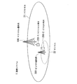
- FIG. 2 is a diagram illustrating a configuration example of the communication system 1 in the first embodiment.
- a pico cell 22 that covers a narrow area exists in a macro cell 21 that covers a wide area.
- one terminal is connected to each cell base station, and a macro cell terminal 200-1 is connected to the macro cell base station (first base station apparatus) 100.
- Macro cell terminal 200-1 and pico cell terminal 200-2 may be collectively referred to as terminal 200.
- the communication system 1 in FIG. 2 is assumed as an example, but the present embodiment can be applied in a multi-cell environment that causes inter-cell interference.
- cells and zones composed of a light projecting base station (RRE: Remote Radio Equipments), a femtocell base station, a relay station, and the like can be targeted, and the number of cells and the number of terminals are the same as those in this embodiment. The number is not limited.
- a communication system in which some areas of the same type of cells overlap as shown in FIG. 3 may be used. This is the same not only in the first embodiment but also in other embodiments.
- FIG. 3 is a configuration example of a communication system in which some areas of the same type of cell overlap. In the figure, it is shown that a part of communication area of the first cell 31 and a part of communication area of the second cell 32 overlap. Also, one terminal device is connected to each cell base station, a terminal device 34 is connected to the first base station 33, and a terminal device 36 is connected to the second base station 35. It is connected.
- the base stations of the plurality of base stations in the present embodiment are connected to each other via a wired network and share information between the base stations.
- the base stations of the plurality of base stations may be connected to each other via a wireless network instead of a wired network.
- the relay station and other base stations can be connected to each other via a wireless network.
- the femtocell base station exchanges information with the macrocell base station 100 via the Internet.
- a light projecting base station or a picocell base station exchanges information with the macrocell base station 100 via an optical fiber or a dedicated network.
- LTE Long Term Evolution
- LTE-A LTE-Advanced
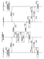
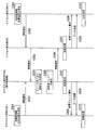
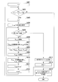
- FIG. 4 is a flowchart illustrating an example of a processing flow of the communication system according to the first embodiment.
- the central control station first base station apparatus
- the macrocell base station 100 is a central control station.
- each terminal (macro cell terminal 200-1 and pico cell terminal 200-2) estimates a propagation path with a base station to which the terminal is connected and a propagation path with an interference station, and estimates The propagated channel is used as channel information.
- each terminal estimates the propagation path of both by using, for example, a reference signal (CRS: Cell Specific Reference Signal or CSI-RS: CSI-Reference Signal) that is being studied by 3GPP. .
- CRS Cell Specific Reference Signal
- CSI-RS CSI-Reference Signal
- each terminal measures the reception quality from the synchronization signal, etc.
- the reception quality is a numerical value including elements related to interference (inter-cell interference) such as reception SINR (signal-to-interference and noise power ratio: Signal to Interference plus Noise power Ratio). It can be measured from the reception level of a reference signal (CRS, CSI-RS, etc.).
- each terminal can obtain information on a cell serving as an interference source from the above synchronization signal and the like.
- step S102 the macro cell terminal 200-1 and the pico cell terminal 200-2 notify the base station to which the terminal is connected of the propagation path information estimated in step S101 and the measured reception quality.
- step S103 the picocell base station 300 notifies the macrocell base station 100 of the information (propagation path information and reception quality) acquired in Step S102 using a wired network.
- each base station other than the central control station performs the process of step S103.
- the macro cell base station 100 performs resource allocation based on the reception quality of each cell.
- the macro cell base station 100 is a coordinated cell (target for performing coordinated control).
- the cell is a macro cell and a pico cell, and the same resource (frequency band) is allocated to the macro cell terminal 200-1 and the pico cell terminal 200-2.
- three resource blocks (RB1 to RB3) are allocated to the cooperative cell.
- the cells that cause interference are the cooperative cells
- the cells included in the cooperative cells are the targets of the cooperative control, and are allocated to the same resource.
- inter-cell interference can be suppressed by cooperative control between cooperative cells.
- the terminals connected to the base stations of these cells can use the same resource, the frequency utilization efficiency is improved.
- a resource allocated to a cooperation cell you may use a resource block with good reception quality of a cooperation cell.
- the cooperative cell and the resource allocation are determined based on the reception quality notified from the terminal.
- the resource allocation is determined according to the information. May be.
- step S105 the macro cell base station 100 calculates transmission / reception weights for performing cooperative control based on the propagation path information.
- IA technology is used as an example of cooperative control.
- Several methods have been proposed as transmission / reception weight calculation methods for realizing the IA technology.
- the macro cell base station 100 according to the present embodiment uses a calculation method based on an iterative algorithm shown in FIG. 9 to be described later.
- the macrocell base station 100 notifies the picocell base station 300 of the transmission / reception weight and resource allocation calculated in step S105 via the wired network.
- the information notified to each cell is only information related to the cell.
- the information notified from the macrocell base station 100 to the picocell base station 300 includes the transmission weight v2, the reception weight u2, and the resource allocation ( Information indicating RB1 to RB3).
- the transmission weight v2, reception weight u2, and resource allocation will be described in detail later.
- the central control station since there is one terminal connected to the picocell base station 300, there is one reception weight to be notified to the picocell base station 300, but there are a plurality of terminals connected to the picocell base station 300. If so, the reception weights of the plurality of terminals are notified.
- the central control station When there are a plurality of base stations other than the central control station, the central control station notifies each base station other than the central control station of the transmission / reception weight and resource allocation calculated for each base station.
- each base station performs transmission processing based on the information notified in S106.
- each base station notifies the reception weight to a terminal connected to the base station.
- each base station transmits data to a terminal connected to the base station.
- each terminal receives a signal transmitted from the base station to which it is connected, and performs a reception process. Further, each terminal estimates propagation path information and reception quality from the received signal. Above, the process of this flowchart is complete
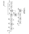
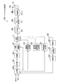
- FIG. 5 is a schematic block diagram illustrating a configuration of the macro cell base station 100 according to the first embodiment.
- the macrocell base station 100 includes a reception antenna 101, a radio unit 102, an A / D (Analog to Digital) conversion unit 103, a reception unit 104, a coding unit 105, a modulation unit 106, a transmission weight multiplication unit 107, and a demodulation reference signal generation unit.
- a / D Analog to Digital
- Transmitting antenna 15 (I is an integer from 1 to N) comprises and upper layer 160.
- the receiving antenna 101 receives a signal transmitted from a terminal to which the receiving antenna 101 is connected, and outputs the received signal to the wireless unit 102 as a received signal.
- Radio section 102 down-converts the received signal input from receiving antenna 101 to generate a baseband signal, and outputs the generated baseband signal to A / D conversion section 103.
- the A / D conversion unit 103 converts the input analog signal into a digital signal, and outputs the digital signal obtained by the conversion to the reception unit 104.
- the receiving unit 104 outputs the channel information estimated by the terminal and the reception quality measured by the terminal to the upper layer from the digital signal input from the A / D conversion unit 103 (see step S102 in FIG. 4).
- the upper layer 160 receives the propagation path information and the reception quality transmitted from the picocell base station 300 via the wired network. Then, upper layer 160 determines the coordinated cell, resource allocation, and transmission / reception weight for each subcarrier based on the received propagation path information and reception quality (see steps S104 and S105 in FIG. 4). Furthermore, upper layer 160 notifies the determined resource allocation and transmission / reception weight for each subcarrier to the base station of each cell (see step S106 in FIG. 4).
- the upper layer 160 outputs the determined resource allocation to the control signal generation unit 110. Further, upper layer 160 outputs the determined transmission weight for each subcarrier to transmission weight multiplication section 107 and demodulation reference signal generation section 108. In addition, upper layer 160 outputs the determined reception weight for each subcarrier to each radio unit 14i.
- Encoding section 105 encodes a transmission bit string input from an upper layer, and outputs the encoded transmission bit string to modulation section 106.
- the modulation unit 106 modulates the encoded transmission bit sequence input from the encoding unit 105 using a modulation scheme such as QPSK (Quadrature Phase Shift Keying) or 16QAM (Quadrature Amplitude Modulation), and obtains a modulation bit sequence obtained by the modulation. Is output to the transmission weight multiplier 107.
- QPSK Quadrature Phase Shift Keying
- 16QAM Quadrature Amplitude Modulation
- Transmission weight multiplication section 107 multiplies the transmission bit string input from modulation section 106 by the transmission weight for each subcarrier input from higher layer 160 and outputs the transmission data signal obtained by the multiplication to signal multiplexing section 111. To do. When performing spatial multiplexing, transmission weight multiplication section 107 multiplies transmission weights for each subcarrier after parallelizing by the number of spatial multiplexing called known layer mapping.
- the demodulation reference signal generation unit 108 generates a demodulation reference signal by multiplying a known reference signal for each subcarrier by a transmission weight for each subcarrier as a demodulation reference signal, and the generated demodulation reference signal is a signal.
- the data is output to the multiplexing unit 111.
- the propagation path estimation reference signal generation unit 109 generates a known reference signal as a propagation path estimation reference signal, and outputs the generated reference signal to the signal multiplexing unit 111.
- Control signal generation section 110 generates control information (information such as resource allocation, modulation scheme, and coding rate) to be notified to the terminal, and outputs the generated control information to signal multiplexing section 111.
- the signal multiplexing unit 111 adds the demodulation reference signal input from the demodulation reference signal generation unit 108 and the propagation input received from the propagation path estimation reference signal generation unit 109 to the transmission data signal input from the transmission weight multiplication unit 107.
- the control information input from the reference signal for path estimation and the control signal generator 110 is multiplexed. Then, the signal multiplexing unit 111 outputs the transmission signal obtained by multiplexing to the IFFT units 121, ..., 12N.
- Each IFFT unit 12i converts the input transmission signal on the frequency axis into a signal on the time axis by IFFT (Inverse Fast Fourier Transform), and after adding a guard interval GI, Are output to the D / A converter 13i having the same index i.
- Each D / A conversion unit 13i converts the signal input from the IFFT unit 12i from a digital signal to an analog signal, and outputs the converted analog signal to the radio unit 14i having the same index i.
- Each wireless unit 14i performs quantization or the like on the reception weight input from the upper layer 160 and converts the received weight into a signal suitable for data communication.
- Each radio unit 14i up-converts the signal obtained by the conversion to a radio frequency, and transmits the up-converted signal to the macro cell terminal 200-1 via the corresponding transmission antenna 15i (see step S108 in FIG. 4). ).
- wireless part 14i in this embodiment is a structure which transmits a receiving weight separately from a control signal, you may multiplex and transmit in a control signal.
- each radio unit 14i up-converts the analog signal input from the corresponding D / A conversion unit 13i to a radio frequency and transmits the radio signal to the macro cell terminal 200-1 via the corresponding transmission antenna 15i (FIG. 4). Step S109).
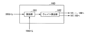
- FIG. 6 is a schematic block diagram showing the configuration of the upper layer 160 in the first embodiment.
- the upper layer 160 includes an allocation unit 161 and a weight calculation unit 162.
- Allocation section 161 receives the reception quality of pico cell 22 transmitted from pico cell base station 300.
- the assigning unit 161 receives the reception quality of the macro cell 21 transferred from the receiving unit 104.
- the assigning unit 161 assigns a frequency band to be used for communication based on the reception quality of each cell (for example, the macro cell 21 and the pico cell 22). Specifically, it is determined whether or not the macro cell and the pico cell interfere with each other based on the reception quality of each cell (information on the cell serving as an interference source). As shown in FIG. 2, when the macro cell and the pico cell interfere with each other, the allocating unit 161 sets the coordinated cells (cells to be subjected to coordinated control) as the macro cell 21 and the pico cell 22, and the macro cell terminal 200-1 and the pico cell. The same resource (frequency band) is allocated to the terminal 200-2.
- the allocating unit 161 allocates, for example, the macro cell terminal 200-1 and the pico cell terminal 200-2 to the frequency band having the best propagation path characteristics. Then, the assigning unit 161 outputs the assignment result to the weight calculating unit 162.
- the weight calculating unit 162 transmits a transmission weight and a reception weight for the terminals assigned by the assigning unit 161 to the same frequency band to perform cooperative control. Is calculated. Details of the calculation of the transmission weight and the reception weight will be described later. Then, weight calculation section 162 outputs the calculated transmission weight multiplication section 107 and demodulation reference signal generation section 108. Also, the weight calculation unit 162 outputs the calculated reception weights to the radio units 141,.
- FIG. 7 is a schematic block diagram illustrating a configuration of the picocell base station 300 according to the first embodiment.
- symbol is attached
- the configuration of the picocell base station 300 in FIG. 7 is obtained by changing the upper layer 160 to the upper layer 160-2 with respect to the configuration of the macrocell base station 100 in FIG.
- the upper layer 160-2 notifies the macro cell base station 100 of the propagation path information and reception quality of each cell via the wired network (see step S103 in FIG. 4).
- the upper layer 160-2 receives resource allocation and transmission / reception weights from the macrocell base station 100. Then, upper layer 160-2 outputs the received resource assignment to control signal generation section 110. Further, upper layer 160-2 outputs the received transmission weight for each subcarrier to transmission weight multiplier 107 and demodulation reference signal generator 108.
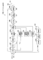
- FIG. 8 is a schematic block diagram illustrating a configuration of the terminal device 200 according to the first embodiment.
- the terminal device 200 includes a receiving antenna 201,..., 20N, a radio unit 211,..., 21N, an A / D conversion unit 221, ..., 22N, an FFT unit 231, ..., 23N, a signal separator 241 and a propagation path estimation unit 242.
- the reception antenna 20i receives a reception signal including a reception weight transmitted from the base station to which the terminal is connected (see step S108 in FIG. 4).
- the reception antenna 20i receives a reception signal including a reference signal (demodulation reference signal and propagation path estimation reference signal), control information, and a reception data signal from the base station to which the terminal is connected.
- a reference signal demodulation reference signal and propagation path estimation reference signal
- Each receiving antenna 20i outputs the received signal received from the base station to which the terminal is connected to the radio unit 21i having the same index i.
- Each radio unit 21i generates a baseband signal by down-converting the reception signal input from the reception antenna 20i, and outputs the generated baseband signal to the corresponding A / D conversion units 221, ..., 22N.
- Each A / D converter 22i converts the input analog signal into a digital signal, and outputs the converted digital signal to the FFT unit 23i having the same index i.
- Each FFT unit 23 i performs FFT (Fast Fourier Transform) on the digital signal input from the A / D conversion unit 22 i, converts the signal into a signal on the frequency axis, and the converted signal to the signal separation unit 241. Output.
- FFT Fast Fourier Transform
- the signal separation unit 241 separates the reference signal (demodulation reference signal and propagation path estimation reference signal) and control information from the signal input from each FFT unit 23i, and transmits the reference signal to the propagation path estimation unit 242 to receive data.
- the signal and the reception weight are output to the reception weight multiplier 243.
- the signal separation unit 241 outputs the separated control information to the reception weight multiplication unit 243, the demodulation unit 245, and the decoding unit 246.
- reception weight multiplication unit 243 multiplies the reception data signal input from the signal separation unit 241 by the reception weight input from the signal separation unit 241, and outputs a signal obtained by the multiplication to the demodulation unit 245.
- reception weight multiplication section 243 refers to the control information (resource allocation) and multiplies the reception data signal in the subcarriers RB1 to RB3 used by each terminal by the reception weight for each subcarrier. .
- Demodulation section 245 demodulates the input received data signal based on the control information (modulation method) input from signal separation section 241, and outputs the obtained received bit string to decoding section 246. Based on the control information (coding rate) input from the signal separator 241, the decoder 246 demodulates the received bit string input from the demodulator 245 to obtain a decoded bit string.
- the propagation path estimation unit 242 estimates propagation path information for each subcarrier from the propagation path estimation reference signal included in the reference signal input from the signal separation unit 241, and outputs the estimated propagation path information to the transmission unit 252. . Further, propagation path estimation section 242 estimates equivalent propagation path information for each subcarrier from the demodulation reference signal included in the reference signal, and outputs the estimated equivalent propagation path information to reception weight multiplication section 243. Equivalent propagation path information represents an equivalent propagation path considering transmission weights multiplied by the base station, and the demodulation reference signal generation unit generates a demodulation reference signal considering transmission weights. An equivalent propagation path can be obtained by receiving this signal.
- each terminal since the macro cell base station 100 calculates the reception weight and notifies each terminal, it is not necessary to calculate the reception weight in each terminal. However, when each terminal calculates the reception weight, each terminal can estimate the equivalent propagation path information by transmitting a known signal (demodulation reference signal) multiplied by the transmission weight. Is not essential, and each terminal can be configured to estimate equivalent channel information. Even when the reception weight is notified, the reception weight may be calculated at each terminal.
- the reception quality estimation unit 251 receives the synchronization signals from the base stations in the neighboring cells, and estimates the reception quality from the reception level obtained from the synchronization signals. If the reception level is higher than a predetermined threshold, reception quality estimation section 251 determines that the base station that transmitted the synchronization signal from which the reception level was obtained is an interference station. The reception quality estimation unit 251 outputs the estimated reception quality (numerical values including elements related to interference and information on cells serving as interference sources) to the transmission unit 252.
- the transmission unit 252 converts the propagation path information input from the propagation path estimation unit 242 and the reception quality input from the reception quality estimation unit 251 into a transmission signal in a transmittable format, and converts the converted transmission signal to D / The data is output to the A conversion unit 253.
- the D / A conversion unit 253 converts the transmission signal input from the transmission unit 252 from a digital signal to an analog signal, and outputs the converted analog signal to the radio unit 254.
- the radio unit 254 transmits the analog signal input from the D / A conversion unit 253 from the transmission antenna 255 to the base station to which the terminal is connected.
- the reception quality estimation unit 251 generates reception quality based on the result of each cell receiving a synchronization signal coming from a neighboring cell.
- the reception quality may be generated based on the above.
- the reception quality estimation unit 251 can control information such as RNTP (relative narrowband Tx Power) that can determine whether the transmission power of each base station is high or low for each resource block between base stations. May be used to generate reception quality.
- RNTP relative narrowband Tx Power
- the reception quality estimation unit 251 can determine that a cell with a low transmission power value is a cell that does not interfere with an adjacent cell, and a cell with a large value is a cell that causes interference with an adjacent cell.
- the reception quality estimation unit 251 may generate reception quality for each resource block by considering the positional relationship and RNTP.
- Hkj (m) represents propagation path information between the j-th (1 ⁇ j ⁇ NBS) -th base station and the k-th (1 ⁇ k ⁇ NUE) -th terminal in the m-th subcarrier
- Hjk ( m) ′ represents propagation path information between the k-th (1 ⁇ k ⁇ NUE) -th terminal and the j-th (1 ⁇ j ⁇ NBS) -th base station in the m-th subcarrier.
- v represents a transmission weight
- u represents a reception weight
- Q is a covariance matrix of received interference signals.
- P is the transmission power
- d is the number of streams to be transmitted.
- X is a resource block number (1 ⁇ x ⁇ number of resource blocks (6 in this embodiment)), and m is a subcarrier number (1 ⁇ m ⁇ last subcarrier number in a communication frame (in this embodiment).
- an arbitrary value can be set as the number of repetitions, and by giving a sufficient number of repetitions, a transmission / reception weight capable of suppressing the influence of more inter-cell interference is calculated. Can do.
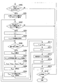
- FIG. 9 is a flowchart showing the flow of transmission / reception weight calculation processing in step S105 of FIG.
- step S201 weight calculation section 162 (FIG. 6) sets the first subcarrier number in RBx as subcarrier number m.
- the weight calculation unit 162 for example, when the resource block number x is 1, the subcarrier number m is 1, and when the resource block number x is 2, the subcarrier number m is 13. Designate the first subcarrier number of each resource block.
- step S202 the weight calculation unit 162 performs a determination to repeat the processing in steps S203 to S214 while the subcarrier number m is equal to or less than the last subcarrier number in RBx. Specifically, weight calculation section 162 determines whether subcarrier number m is equal to or smaller than the last subcarrier number in RBx. If the subcarrier number m is equal to or less than the last subcarrier number in RBx (YES in step S202), the weight calculation unit 162 transitions to step S203. When the subcarrier number m exceeds the last subcarrier number in RBx (NO in step S202), the weight calculation unit 162 transitions to step S215.
- step S203 the weight calculation unit 162 initializes the index n to 1.
- step S204 the weight calculation unit 162 sets an arbitrary initial value for the transmission weight vj (m).
- step S205 the weight calculation unit 162 determines to repeat the processing in steps S205 to S212 while the index n is equal to or less than a predetermined number of repetitions. Specifically, the weight calculation unit 162 determines whether the index n is equal to or less than the number of repetitions. When the index n is less than or equal to the number of repetitions (YES in step S205), the weight calculation unit 162 transitions to step S206. If the index n exceeds the number of repetitions (NO in step S205), the weight calculation unit 162 transitions to step S213.
- step S206 the weight calculation unit 162 calculates an interference covariance matrix Qk (m) based on the propagation path information and the transmission weight. Specifically, for example, the weight calculation unit 162 calculates the covariance matrix Qk (m) according to the following equation (1).
- the weight calculation unit 162 calculates a reception weight based on the calculated interference covariance matrix Qk (m). Specifically, in step S207, for example, the weight calculation unit 162 performs singular value decomposition on the interference covariance matrix Qk (m), and calculates a reception weight uk (m).
- the weight calculation unit 162 extracts columns for the number of streams from the right in the left singular vector (number of reception antennas, number of reception antennas) and sets it as a reception weight uk (m).
- step S208 the weight calculation unit 162 substitutes the value of the reception weight uk (m) calculated for the transmission weight vk (m) ′, and sets Hkj (m) H to the propagation path information Hjk (m) ′. Assign a value.
- the weight calculation unit 162 calculates an interference covariance matrix Qj (m) ′ based on the propagation path information and the reception weight. Specifically, for example, the weight calculation unit 162 calculates an interference covariance matrix Qj (m) ′ according to the following equation (2).
- the weight calculation unit 162 calculates a transmission weight based on the calculated interference covariance matrix Qj (m) ′. Specifically, for example, in step S210, the weight calculation unit 162 calculates a reception weight uj (m) ′ by performing singular value decomposition on the interference covariance matrix Qj (m) ′. Then, as in step S207, the weight calculation unit 162 selects the left singular vectors obtained by performing singular value decomposition on Qj (m) ′, corresponding to the smaller singular values, for the number of streams, and receives the weights uj. (M) ′. Specifically, the weight calculation unit 162 extracts a sequence corresponding to the number of streams from the right in the left singular vector (transmission antenna number row, transmission antenna number sequence) and sets it as a reception weight uj (m) ′.
- step S211 the weight calculation unit 162 substitutes the calculated reception weight uj (m) ′ for the transmission weight vj (m).
- step S212 the weight calculation unit 162 adds 1 to the index n, and the process proceeds to step S204. Accordingly, in step S204, the weight calculation unit 162 compares the value of index n with the number of repetitions, performs the processing of steps S205 to S212 for a predetermined number of repetitions, and index n exceeds the predetermined number of repetitions. If so (NO at step S205), the process proceeds to step S213.
- step S213 the weight calculation unit 162 uses the obtained transmission weight vj (m) as the transmission weight in the m-th subcarrier and the complex conjugate transposed vector uk (m) H of the reception weight uk (m) as m. It is assumed that the reception weight in the th subcarrier.
- step S214 the weight calculation unit 162 adds 1 to the subcarrier number m, and proceeds to step S202.
- the weight calculation unit 162 repeats the processing of steps S203 to S213 for the number of subcarriers in RBx, and if the subcarrier number m exceeds the last subcarrier number in RBx (NO in step S202), the process proceeds to step S215.
- step S215 the weight calculation unit 162 adds 1 to the resource block number x, and the process proceeds to step S216.
- step S216 the weight calculation unit 162 determines whether the resource block number x is equal to or less than the number of resource blocks (the number of RBs, 6 in the present embodiment). If the resource block number x is equal to or less than the number of RBs (YES in step S216), the weight calculation unit 162 transitions to step S200 and performs processing for the next resource block.
- the weight calculation unit 162 repeats the above process for the number of resource blocks, and when the resource block number x exceeds the number of RBs (NO in step S216), the process ends. Above, the process of this flowchart is complete
- the weight calculation unit 162 repeatedly updates the weight so as to use a weight corresponding to a small singular value (a weight that reduces the interference power). Therefore, the weight calculation unit 162 can obtain a weight capable of suppressing the influence of interference as a transmission / reception weight after a predetermined number of repetitions. By using the transmission / reception weight obtained in this way, the communication system 1 in the present embodiment can suppress the influence of interference in cooperation with a plurality of cells.
- This algorithm is an example, and other algorithms may be used.
- FIG. 10 is a diagram illustrating a process of calculating a transmission weight and a reception weight by the processing in FIG.
- the process is divided into a transmission weight calculation process and a reception weight calculation process.
- the weight calculation unit 162 assigns an initial value to the transmission weight vj (m) (step S204).
- the weight calculation unit 162 calculates a covariance matrix Qk (m) (step S205).
- the weight calculation unit 162 performs singular value decomposition on the covariance matrix Qk (m) and calculates a reception weight uk (m) (step S207).
- the weight calculation unit 162 substitutes the calculated value of the reception weight uk (m) for the transmission weight vk (m) ′, and substitutes the value of Hkj (m) H for the propagation path information Hjk (m) ′. (Step S208).
- the weight calculation unit 162 calculates the covariance matrix Qj (m) ′ of interference (step S209).
- the weight calculation unit 162 performs singular value decomposition on the interference covariance matrix Qj (m) ′ to calculate a reception weight uj (m) ′ (step S210).
- the weight calculation unit 162 substitutes the calculated reception weight uj (m) ′ for the transmission weight vj (m) (step S211).
- the weight calculation unit 162 performs the processing of steps S206 to S208 to update the reception weight uk (m).
- the weight calculation unit 162 performs the processing of steps S209 to S211 to update the transmission weight vj (m).
- the weight calculation unit 162 updates the reception weight uk (m) and the transmission weight vj (m) until the index n is 3 to n ⁇ 1.
- the weight calculation unit 162 performs the processing of steps S206 to S208 and updates the reception weight uk (m).
- the weight calculation unit 162 performs the processing of steps S209 to S211 to update the transmission weight vj (m).
- the weight calculation unit 162 sets the obtained transmission weight vj (m) as the transmission weight in the mth subcarrier and the reception weight uk (m) as the reception weight in the mth subcarrier. As described above, the weight calculation unit 162 calculates the transmission weight vj (m) and the reception weight uk (m).
- the weight calculation unit 162 may use a coordinated transmission beamforming technique, and the weight calculation unit 162 uses the propagation path information as shown in the following equation (3), for example, for the cell j (1 ⁇ j ⁇
- the transmission weight vk (m) at the base station of NBS may be calculated.
- Equation (3) is a ZF (Zero Forcing) type transmission weight, but other transmission weights may be used.
- ⁇ Effect of the first embodiment> As described above, for example, when three resource blocks are allocated to each cell, in the conventional technique, in consideration of the influence of inter-cell interference, adjustment is performed so that resource allocation does not overlap for each cell. A block is required. However, in this embodiment, since inter-cell interference can be suppressed by cooperative control, the same resource can be allocated in the macro cell and the pico cell, and the necessary resources are three resource blocks. Thereby, in the communication system of the first embodiment, when the same resource is allocated to a plurality of cells in a multi-cell environment, it is not necessary to change to another resource in order to avoid inter-cell interference. Frequency utilization efficiency can be improved.
- a macro cell base station allocates a plurality of cells to the same resource and suppresses inter-cell interference by cooperative control, so that a terminal device can obtain good throughput. That is, the communication system according to the first embodiment can obtain a good throughput while improving the frequency utilization efficiency in a multi-cell environment.
- the number of subcarriers for calculating one transmission / reception weight is defined as a weight unit, and in this embodiment, as an example, the weight unit is one resource block (12 subcarriers in the example of FIG. 1).
- the terminal determines the weight unit.
- the base station may determine and control the weight unit.
- the weight unit may be set in advance by the system.
- FIG. 11 is a diagram illustrating a configuration example of a communication system 1b according to the second embodiment. Elements common to those in FIG. 2 are denoted by the same reference numerals, and detailed description thereof is omitted.
- 11 is different from the configuration of the communication system 1 in FIG. 2 in that the macro cell base station 100 is the macro cell base station (first base station apparatus) 100b and the macro cell terminal 200-1 is the macro cell terminal 200b. ⁇ 1, the pico cell terminal 200b-2 is changed to the pico cell terminal 200b-2. Further, the macro cell 11 is changed to the macro cell 21, and the pico cell 12 is changed to the pico cell 22.
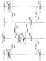
- FIG. 12 is a flowchart illustrating an example of a processing flow of the communication system according to the second embodiment. Steps S301, S307, S309, and S310 are the same as steps S101, S107, S109, and S110 in FIG. Hereinafter, differences from the first embodiment will be described with reference to FIG.
- each terminal notifies the base station to which the terminal is connected of the propagation path information and the reception quality for each designated weight unit.
- the weight unit is one resource block as an example
- the propagation path information and the reception quality are one value (hereinafter also referred to as a representative value) for each resource block.
- the number of feedbacks for each piece of information is six.
- each terminal can calculate, for example, the average value of the propagation path information for each weight unit as a representative value of the propagation path information, or in one of the subcarriers to which the reference signal is assigned.
- the propagation path information can also be calculated as a representative value.
- Each terminal can also calculate, for example, an average value of the reception quality for each weight unit as a representative value of the reception quality, and can determine the reception quality in one subcarrier among the subcarriers to which the reference signal is assigned. It can also be calculated as a representative value.
- the feedback of the representative value of the propagation path information or the reception quality may be a feedback of the representative value obtained by the terminal, or may be feedback of other information, for example, a code book, a value obtained by compressing information.
- the weight unit may be the same or different at each terminal. More specifically, among the plurality of terminal devices, the weight unit of at least one terminal device may be different from the weight units of other terminal devices.
- the weight unit When the weight unit is the same in each terminal, the amount of information for notifying the weight unit can be reduced, so that transmission efficiency is improved. On the other hand, when the weight unit is different for each terminal, the weight can be calculated in a unit suitable for each terminal, so that transmission performance can be improved.
- each terminal in the first embodiment notifies the base station to which the terminal is connected of the propagation path information and reception quality in all subcarriers.
- each terminal in the second embodiment, notifies the base station to which the terminal is connected of one piece of propagation path information and one reception quality for each designated weight unit. The amount of communication (feedback amount) can be reduced. Furthermore, in step S302, each terminal notifies the weight unit to the base station to which the terminal is connected.
- step S303 the pico cell base station 300 notifies the macro cell base station 100b of the information acquired in step S302 using a wired network.
- these base stations perform the process of step S303.
- the pico cell base station 300 is notified of information indicating the representative value of the propagation path information from the pico cell terminal apparatus 200b-2, the following processing is performed.
- the picocell base station 300 which is a base station device other than the macrocell base station 100b, transmits information indicating the representative value of the propagation path information notified from the picocell terminal device 200b-2 to the macrocell base station 100b via a wired network or a wireless network. You may be notified.
- the macro cell base station 100b determines resource allocation based on the reception quality for each weight unit notified from each terminal.
- the resource allocation in this embodiment is RB1 to RB3, as in the first embodiment.
- step S305 the macro cell base station 100b calculates a transmission / reception weight for each weight unit.
- transmission / reception weights are calculated for each subcarrier with respect to allocated resources (RB1 to RB3) based on propagation path information for each subcarrier.
- transmission / reception weights are calculated for each weight unit for allocated resources based on the six propagation path information fed back from each terminal.
- the macro cell base station 100b calculates three transmission / reception weights.
- step S302 when the terminal apparatus uses the reference signal to obtain the representative value of the propagation path information in the weight unit, the macro cell base station 100b uses the representative value of the propagation path information for each weight unit.
- the transmission weight or the reception weight may be calculated. Further, the macro cell base station 100b may calculate a transmission weight or a reception weight for each unit different from the weight unit using the representative value of the propagation path information.
- the transmission / reception weight notified in step S306 and the reception weight notified in step S308 are each three.
- FIG. 13 is a schematic block diagram of the terminal device 200b according to the second embodiment.
- symbol is attached
- the configuration of the terminal device 200b in FIG. 13 is different from the configuration of the terminal device 200 in FIG. 8 in that the reception weight multiplication unit 243 is in the reception weight multiplication unit 243b and the propagation path estimation unit 242 is in the propagation path estimation unit 242b.
- the estimation unit 251 is changed to a reception quality estimation unit 251b.
- the reception weight multiplication unit 243b has the same function as the reception weight multiplication unit 243 in the first embodiment, but differs in the following points.
- the propagation path estimation unit 242b has the same function as the propagation path estimation unit 242 in the first embodiment, but differs in the following points.
- the propagation path estimation unit 242b calculates a representative value of propagation path information for each weight unit. Specifically, for example, the propagation path estimation unit 242b estimates propagation path information for each subcarrier. And the propagation path estimation part 242b averages the propagation path information calculated for every subcarrier in a weight unit, and calculates the average value as a representative value of propagation path information.
- the reception quality estimation unit 251b has the same function as the reception quality estimation unit 251 in the first embodiment, but differs in the following points.
- the reception quality estimation unit 251b calculates a representative value of reception quality for each weight unit. Specifically, for example, the reception quality estimation unit 251b estimates reception quality for each subcarrier. Then, reception quality estimation section 251b averages the reception quality calculated for each subcarrier in units of weights, and calculates the average value as a representative value of reception quality.
- FIG. 14 is a schematic block diagram of the macro cell base station 100b according to the second embodiment.
- symbol is attached
- the macro cell base station 100b in FIG. 14 is different from the macro cell base station 100 in FIG. 5 in that the reception unit 104 is in the reception unit 104b, the transmission weight multiplication unit 107 is in the transmission weight multiplication unit 107b, and the upper layer 160 is The upper layer 160b has been changed.
- the receiving unit 104b has a function similar to that of the receiving unit 104 of the first embodiment, but differs in the following points.
- the receiving unit 104b outputs the weight unit included in the transmission signal transmitted from the macro cell terminal 200-1 to the upper layer 160b.
- the transmission weight multiplication unit 107b has the same function as the transmission weight multiplication unit 107 of the first embodiment, but differs in the following points.
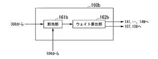
- FIG. 15 is a schematic block diagram of the upper layer 160b in the second embodiment.
- the upper layer 160b includes an allocation unit 161b and a weight calculation unit 162b.
- the allocation unit 161b determines resource allocation based on the reception quality for each weight unit notified from each terminal.
- the allocation unit 161b outputs an allocation result indicating the determined resource allocation result to the weight calculation unit 162b.
- the weight calculation unit 162b acquires the allocated resource from the allocation result input from the allocation unit 161b.
- the weight calculation unit 162b calculates transmission / reception weights for each weight unit for the resources allocated by the allocation unit 161b based on the six propagation path information fed back from each terminal.
- the feedback number w (1 ⁇ w ⁇ number of feedback) is set in the present embodiment, and the first embodiment is used.
- the index m such as Hkj (m) is replaced with the feedback number w.
- FIG. 16 is a flowchart showing a flow of processing of transmission / reception weight calculation in the second embodiment.
- the weight calculation unit 162b initializes the feedback number w to 1.
- step S402 the weight calculation unit 162b repeats the processing in steps S403 to S414 while the feedback number w is equal to or less than the feedback number, and calculates transmission / reception weights for each weight unit. Specifically, the weight calculation unit 162b determines whether or not the feedback number w is equal to or less than the number of feedbacks. When the feedback number w is less than or equal to the number of feedback (step S402 YES), the weight calculation unit 162b transitions to step S403. On the other hand, when the feedback number w exceeds the feedback number (NO in step S402), the weight calculation unit 162b transitions to step S415.
- Steps S403 to S414 in FIG. 16 are the same processes as steps S203 to S214 in FIG. 9, respectively, and the indexes to be processed are different as described above. That is, in FIG. 9, the weight calculation unit 162 calculates transmission / reception weights for each subcarrier based on the subcarrier number m. In FIG. 16, the weight calculation unit 162b calculates a transmission / reception weight for each feedback unit (weight unit) based on the feedback number w.
- step S415 of FIG. 16 the transmission / reception weights of RB1 to RB3 designated for resource allocation are extracted from the transmission / reception weights (six in this embodiment) calculated in step S413. Thus, the process of this flowchart is completed.
- the macro cell base station 100b can calculate the transmission / reception weight for each weight unit for the resource block designated for resource allocation.
- the communication system 1b of the second embodiment allows the terminal device 200b to transmit the propagation path information and the reception quality that are fed back from the terminal device 200b to the base station. Are calculated for each weight unit, so that the amount of feedback to the base station can be reduced.
- the weight unit is one resource block (12 subcarriers), but it can be specified as a natural number multiple of the resource block. For example, when the weight unit is specified as 3 resource blocks, the number of feedbacks from the terminal to the base station is 2 (the channel information to be fed back and the reception quality are the average values of RB1 to RB3 and RB4 to RB6, respectively)
- the central control station may allocate resources to any one of RB1 to RB3 or RB4 to RB6, and the weight calculation unit 162b may calculate one transmission / reception weight.
- the weight unit in the present embodiment may be specified by the number of subcarriers instead of the resource block unit. That is, even if a method in which the resource allocation unit and the feedback control unit are different, such as designation in a resource unit different from the resource block such as every 16 subcarriers, is used without departing from the scope of the present invention.
- the weight unit may be changed depending on the frequency band. For example, one resource block unit may be specified for RB1 to RB2, and two resource block units may be specified for RB3 to RB6. That is, the macro cell base station 100b may calculate the transmission weight and the reception weight in units of natural number times the resource block.
- the macro cell base station 100b may calculate the transmission weight and the reception weight in units of a plurality of types of resource blocks.
- the weight calculation unit may change for each weight.
- the weight calculation unit considers the frequency selectivity (for example, frequency correlation) of the propagation path. When the frequency selectivity is low, that is, when the frequency correlation is high, the weight calculation unit is increased and the frequency selectivity is high, that is, the frequency. If the weight calculation unit is changed, such as reducing the weight calculation unit when the correlation is low, the weight calculation unit can be made suitable from the viewpoint of reducing the amount of calculation and improving the transmission characteristics.
- the macro cell base station 100b may calculate the transmission weight and the reception weight for each predetermined calculation unit.
- the weight calculation unit may be larger than the feedback unit such that the terminal device 200b feeds back the propagation path information for each resource block and the macro cell base station 100b obtains the transmission / reception weight for every two resource blocks.
- the calculation amount of the macro cell base station 100b can be reduced by reducing the number of weights to be calculated, and the amount of control information for the macro cell base station 100b to notify the terminal device 200b of the weight can be reduced.
- the weight calculation unit is smaller than the feedback unit, such that the terminal device 200b feeds back the propagation path information every two resource blocks, and the macro cell base station 100b interpolates the feedback information and obtains the weight for each resource block. Also good.
- the terminal device 200b designates the weight unit.
- the macro cell base station 100b may designate the weight unit. In that case, the macro cell base station 100b transmits a weight unit to each base station apparatus. Thereby, the weight unit is notified from each base station apparatus to each terminal apparatus 200b with which each communicates.
- the unit for calculating the transmission / reception weight is the same for the transmission weight and the reception weight.
- the transmission weight is for each designated weight unit, and the reception weight. Is calculated for each subcarrier regardless of the weight unit.
- a terminal device may produce
- FIG. 17 is a diagram illustrating a configuration example of a communication system 1c according to the third embodiment. Elements common to those in FIG. 2 are denoted by the same reference numerals, and detailed description thereof is omitted. 17 is different from the configuration of the communication system 1 in FIG. 2 in that the macro cell base station 100 is changed to a macro cell base station (first base station apparatus) 100c, and the macro cell terminal 200-1 is changed to a macro cell. The terminal is changed to the terminal 200c-1, and the pico cell terminal 200b-2 is changed to the pico cell terminal 200c-2.
- the macro cell base station 100 is changed to a macro cell base station (first base station apparatus) 100c
- the macro cell terminal 200-1 is changed to a macro cell.
- the terminal is changed to the terminal 200c-1
- the pico cell terminal 200b-2 is changed to the pico cell terminal 200c-2.
- FIG. 18 is a flowchart illustrating an example of a processing flow of the communication system according to the third embodiment.
- the processing flow of the communication system 1c in the third embodiment requires only a transmission weight in the macro cell base station 100c of the third embodiment. It is different in point to do.
- Steps S501 to S504, S507, and S509 are the same as steps S101 to S104, S107, and S109 in FIG.
- differences from the first embodiment will be described with reference to FIG.
- step S505 the macro cell base station 100c calculates a transmission weight and resource allocation.
- step S506 the macrocell base station 100c notifies the picocell base station 300 of the transmission weight and resource allocation calculated in step S505 via a wired network. That is, the macro cell base station 100c does not notify each terminal of the reception weight calculated in step S505.
- step S510 each terminal receives a signal transmitted from a base station to which it is connected, and performs reception processing. At that time, each terminal calculates a reception weight based on the received signal. Each terminal then restores the transmission signal by multiplying the received data signal by the calculated reception weight.
- FIG. 19 is a schematic block diagram of a macro cell base station 100c according to the third embodiment.
- symbol is attached
- the configuration of the macro cell base station 100c in FIG. 19 is different from the configuration of the macro cell base station 100 in FIG. 5 in that the upper layer 160 is changed to the upper layer 160c, and the radio units 141,. ..., changed to 14Nc.
- the upper layer 160c has the same function as the upper layer 160 in the first embodiment, but differs in the following points.
- the upper layer 160c calculates a transmission weight and resource allocation.
- the upper layer 160c does not calculate the reception weight and does not output the reception weight to the radio units 141-c,..., 14N-c. Thereby, radio sections 141-c,..., 14N-c do not transmit reception weights to macro cell terminal 200-1.
- FIG. 20 is a schematic block diagram of a terminal device 200c according to the third embodiment.
- symbol is attached
- the configuration of the terminal device 200c in FIG. 20 is the same as the configuration of the terminal device 200 in FIG. 8 except that a reception weight calculation unit 247c is added, the signal separation unit 241 is changed to the signal separation unit 241c, and the propagation path estimation unit 242 It is changed to the propagation path estimation unit 242c, and the reception weight multiplication unit 243 is changed to the reception weight multiplication unit 243c. That is, the difference from the first and second embodiments is that the third embodiment includes a reception weight calculation unit 247c.
- the signal separation unit 241c separates the reference signal (demodulation reference signal and propagation path estimation reference signal) and control information from the input signal. Then, the signal separation unit 241c outputs the reference signal to the propagation path estimation unit 242c. Further, the signal separation unit 241c outputs the received data signal remaining after the reference signal and control information are separated from the input signal to the reception weight multiplication unit 243c. Further, the signal separation unit 241 outputs the control information to the reception weight multiplication unit 243c, the demodulation unit 245c, and the decoding unit 246c.
- the propagation path estimation unit 242c calculates equivalent propagation path information H ′′ k (m) for each subcarrier, and outputs the calculated equivalent propagation path information H ′′ k (m) for each subcarrier to the reception weight calculation section 247c. . Based on the equivalent propagation path information H ′′ k (m) for each subcarrier input from the propagation path estimation section 242c, the reception weight calculation section 247c calculates a reception weight, for example, as in the following equation (4).
- Equation (4) is a reception weight based on the MMSE (Minimum Mean Square Error) standard, but other reception weights may be used.
- the reception weight calculation unit 247c outputs the calculated reception weight to the reception weight multiplication unit 243c.
- the reception weight multiplication unit 243c multiplies the reception data signal input from the signal separation unit 241 by the reception weight input from the reception weight calculation unit 247c, and outputs a signal obtained by the multiplication to the demodulation unit 245.
- the macrocell base station 100c may notify the terminals by thinning them out. Thereby, the macrocell base station 100c can reduce the notification amount of the reception weight. Even if the reception weight is notified, the terminal device 200c can calculate the weight in units of subcarriers. As a result, when an error occurs between the propagation path for which the macrocell base station 100c calculates the weight and the propagation path when the terminal apparatus 200c receives, such as when the terminal apparatus 200c is moving, the influence of this error is reduced. be able to. In the third embodiment, the terminal device 200c calculates the weight in units of subcarriers.
- the present invention is not limited to this, and the reception weight may be calculated in a unit different from the transmission weight calculation unit. It is included in the present invention.
- the terminal device 200c may calculate a reception weight for each resource block or may calculate a reception weight for every three resource blocks. Good. If the reception weight calculation unit of the terminal device 200c is increased, the amount of calculation can be reduced, and if the reception weight calculation unit is decreased, the transmission characteristics can be improved.
- a program for executing each process of the base station and the terminal device of the present embodiment is recorded on a computer-readable recording medium, and the program recorded on the recording medium is read into a computer system and executed.
- the various processes described above in the base station and the terminal device may be performed.
- the “computer system” referred to here may include an OS and hardware such as peripheral devices. Further, the “computer system” includes a homepage providing environment (or display environment) if a WWW system is used.
- the “computer-readable recording medium” means a flexible disk, a magneto-optical disk, a ROM, a writable nonvolatile memory such as a flash memory, a portable medium such as a CD-ROM, a hard disk built in a computer system, etc. This is a storage device.
- the “computer-readable recording medium” refers to a volatile memory (for example, DRAM (Dynamic) in a computer system serving as a server or a client when a program is transmitted via a network such as the Internet or a communication line such as a telephone line. Random Access Memory)), etc. that hold a program for a certain period of time.
- the program may be transmitted from a computer system storing the program in a storage device or the like to another computer system via a transmission medium or by a transmission wave in the transmission medium.
- the “transmission medium” for transmitting the program refers to a medium having a function of transmitting information, such as a network (communication network) such as the Internet or a communication line (communication line) such as a telephone line.
- the program may be for realizing a part of the functions described above. Furthermore, what can implement
- Communication system 100, 100b, 100c Macrocell base station (first base station apparatus) DESCRIPTION OF SYMBOLS 101 Reception antenna 102 Radio
Landscapes
- Engineering & Computer Science (AREA)
- Signal Processing (AREA)
- Computer Networks & Wireless Communication (AREA)
- Quality & Reliability (AREA)
- Mobile Radio Communication Systems (AREA)
Abstract
セル間の干渉を抑えつつ、周波数利用効率を向上させる。 基地局装置と少なくとも一つの端末装置とが通信を行う通信エリアが複数存在し、複数の通信エリアが隣接または重複し合う通信システム1であって、 複数の通信 エリアのうち一つの通信エリア内のマクロセル基地局装置100が、複数の通信エリアの端末装置を同じ周波数帯に割り当て、マクロセル基地局装置100は、同じ周波数帯に割り当てた端末同士が協調制御を行うための送信ウェイトと受信ウェイトを算出する。
Description
本発明は、通信システム、通信方法、基地局装置及び端末装置に関する。
次世代移動通信システムでは、マクロセル内にピコセル基地局やフェムトセル基地局のような小規模な基地局を配置し、マクロセル基地局に接続する端末を小規模な基地局にオフロードすることにより、マクロセル基地局のトラフィック負荷を小規模な基地局に分散させることが検討されている。しかし、小規模な基地局(例えば、ピコセル基地局)はマクロセル基地局よりも送信電力が低いため、マクロセル基地局からピコセル基地局へオフロードできる端末は限定され、ピコセル基地局の配置によるトラフィック分散の効果が十分に得られない。
そこで、3GPP(3rd Generation Partnership Project)では、ピコセル基地局の送信電力に等価的なオフセットを与え、ピコセル基地局の見かけ上のセル半径を増大させるCRE(Cell Range Expansion)が提案されている。これにより、特にマクロセルとピコセルのセル境界に位置していた端末は、マクロセル基地局からピコセル基地局へ接続先を変更することが可能になり、マクロセル基地局のトラフィック負荷をピコセル基地局に分散させることができる。
しかし、CREの適用により、特にマクロセル基地局からピコセル基地局へ接続先を変更した端末は、マクロセル基地局からのセル間干渉を受ける。このとき、マクロセル基地局はピコセル基地局よりも送信電力が高いため、マクロセル基地局から受ける干渉は大きな干渉となる。このようなセル間干渉の影響を抑圧する方法として、例えば、非特許文献1のように、セル毎に異なる時間リソースを割り当てて伝送する方法が検討されている。したがって、非特許文献1のように、セル毎に異なる時間リソースを割り当てることによって、セル間干渉の影響を回避することができる。
3GPP TS 36.300 V10.5.0(Release10)
一方、次世代移動通信システムの多くでは、多元接続方式としてOFDMA(Orthognal Frequency Division Multiple Access)が採用されており、所定の周波数帯域や時間区間から構成される領域を割り当て単位として、複数の端末のデータが割り当てられる。
図1は、通信フレームの構成を示す説明のための単なる例示である。同図において、縦軸は周波数、横軸は時間である。通信フレームは周波数軸上では六つのリソースブロック(Resource Block:RB)で構成される。この六つのリソースブロックは、太線で囲まれた範囲である。ここで、RBとは、無線リソース割り当ての最小単位である。同図では、簡単のため、通信フレームに含まれる時間軸上のRBのうち、一つのRBだけを示している。図1のRB1の拡大図11の例では、一つのRBは12サブキャリア、7シンボルで構成される。
このとき、各端末は周波数毎に受信品質が異なるため、割り当てられるリソースブロック毎に受信品質が異なる。そこで、基地局は、各端末を受信品質の良いリソースブロックに割り当てられるよう、スケジューリングと呼ばれる処理を行うことで、スループットの高い伝送を実現可能である。
しかし、複数のセルが存在するマルチセル環境において、各セルの基地局がそれぞれ独立にスケジューリングを行う場合、異なるセル間でリソース割り当てが重複し、セル間干渉が生じる。例えば、一つのマクロセルと一つのピコセルで構成されるシステムにおいて、一つのセルに三つのリソースブロックを割り当てる場合、マクロセル端末(マクロセル基地局に接続する端末)とピコセル端末(ピコセル基地局に接続する端末)が同じリソースブロック(例えば、図1のRB1、RB2、RB3)に割り当てられると、マクロセル基地局とピコセル基地局が同じ周波数を用いて伝送を行うことになり、セル間干渉が生じる。
そこで、例えば、非特許文献1の技術を用いて、リソース割り当てが重複した端末同士を異なるリソースに割り当てることによって、セル間干渉を抑圧することが可能であるが、セル数の増加に伴い、より多くのリソースが必要となり、周波数利用効率が悪くなるという問題があった。
例えば、先に述べた例(マクロセル端末及びピコセル端末のリソース割り当てがそれぞれ図1のRB1、RB2、RB3の場合)において、マクロセル端末とピコセル端末のリソース割り当てが異なるリソースとなるようセル間で調整するため、六つのリソースブロック(図1のRB1~RB6)が必要となる。
例えば、先に述べた例(マクロセル端末及びピコセル端末のリソース割り当てがそれぞれ図1のRB1、RB2、RB3の場合)において、マクロセル端末とピコセル端末のリソース割り当てが異なるリソースとなるようセル間で調整するため、六つのリソースブロック(図1のRB1~RB6)が必要となる。
そこで本発明は、上記問題に鑑みてなされたものであり、セル間の干渉を抑えつつ、周波数利用効率を向上させることを可能とする通信システム、通信方法、基地局装置及び端末装置を提供することを課題とする。
(1)本発明は前記事情に鑑みなされたもので、本発明の一態様は、基地局装置と少なくとも一つの端末装置とが複数のリソースを用いて通信を行う通信エリアが複数存在し、前記複数の通信エリアが隣接または重複し合う通信システムであって、前記複数の通信エリアのうち一つの通信エリアにおける基地局である第一の基地局装置は、前記複数のリソースのうち同じリソースに割り当てられている前記端末装置に対する前記複数の基地局装置における送信ウェイトを算出し、各基地局装置は通知された前記送信ウェイトが乗算された信号を前記端末装置へ送信することを特徴とする通信システムである。
(2)上記に記載の通信システムにおいて、本発明の一態様は、前記第一の基地局装置は、前記端末装置それぞれにおける受信ウェイトを更に算出し、前記端末装置はそれぞれ前記受信ウェイトを用いて復調することを特徴とする。
(3)上記に記載の通信システムにおいて、本発明の一態様は、前記第一の基地局装置は、ウェイト算出の単位であるウェイト単位で前記送信ウェイトを算出することを特徴とする。
(4)上記に記載の通信システムにおいて、本発明の一態様は、前記第一の基地局装置は、ウェイト算出の単位であるウェイト単位で前記送信ウェイト及び前記受信ウェイトを算出することを特徴とする。
(5)上記に記載の通信システムにおいて、本発明の一態様は、前記ウェイト単位は、前記端末装置から前記各基地局装置に通知されることを特徴とする。
(6)上記に記載の通信システムにおいて、本発明の一態様は、前記ウェイト単位は、前記各基地局装置から前記端末装置に通知されることを特徴とする。
(7)上記に記載の通信システムにおいて、本発明の一態様は、前記端末装置は、参照信号を用いて、前記ウェイト単位の伝搬路情報の代表値を求め、該求めた伝搬路情報の代表値を示す情報を前記基地局装置に通知することを特徴とする。
(8)上記に記載の通信システムにおいて、本発明の一態様は、前記伝搬路情報の代表値は、前記ウェイト単位の平均値であることを特徴とする通信システムである。
(9)上記に記載の通信システムにおいて、本発明の一態様は、前記伝搬路情報の代表値は、前記ウェイト単位のうち、前記参照信号が割り当てられているサブキャリアの伝搬路情報であることを特徴とする。
(10)上記に記載の通信システムにおいて、本発明の一態様は、前記第一の基地局装置は、前記伝搬路情報の代表値を用いて前記ウェイト単位毎に前記送信ウェイトを算出することを特徴とする。
(11)上記に記載の通信システムにおいて、本発明の一態様は、前記第一の基地局装置は、前記伝搬路情報の代表値を用いて前記ウェイト単位毎に前記送信ウェイト又は前記受信ウェイトを算出することを特徴とする。
(12)上記に記載の通信システムにおいて、本発明の一態様は、前記第一の基地局装置は、前記伝搬路情報の代表値を用いて前記ウェイト単位とは異なる単位毎に前記送信ウェイトを算出することを特徴とする。
(13)上記に記載の通信システムにおいて、本発明の一態様は、前記第一の基地局装置は、前記伝搬路情報の代表値を用いて前記ウェイト単位とは異なる単位毎に前記送信ウェイト又は前記受信ウェイトを算出することを特徴とする。
(14)上記に記載の通信システムにおいて、本発明の一態様は、前記送信ウェイトの算出単位と前記受信ウェイトの算出単位は異なることを特徴とする。
(15)上記に記載の通信システムにおいて、本発明の一態様は、前記ウェイト単位は、サブキャリア単位であることを特徴とする。
(16)上記に記載の通信システムにおいて、本発明の一態様は、前記ウェイト単位は、リソースブロックの自然数倍の単位であることを特徴とする。
(17)上記に記載の通信システムにおいて、本発明の一態様は、前記ウェイト単位は、複数の種類のリソースブロック単位であることを特徴とする。
(18)上記に記載の通信システムにおいて、本発明の一態様は、前記複数の端末装置のうち、少なくとも一つの端末装置の前記ウェイト単位が他の端末装置のウェイト単位と異なることを特徴とする。
(19)上記に記載の通信システムにおいて、本発明の一態様は、前記端末装置は、前記ウェイト単位で受信ウェイトを生成することを特徴とする。
(20)上記に記載の通信システムにおいて、本発明の一態様は、前記端末装置は、前記ウェイト単位とは異なる単位で受信ウェイトを生成することを特徴とする。
(21)上記に記載の通信システムにおいて、本発明の一態様は、前記端末装置は、サブキャリア単位で受信ウェイトを生成することを特徴とする。
(22)上記に記載の通信システムにおいて、本発明の一態様は、前記複数の通信エリアそれぞれにおける基地局装置は有線ネットワークまたは無線ネットワークで相互に接続されており、前記第一の基地局装置以外の基地局装置は、前記端末装置から通知された前記伝搬路情報の代表値を示す情報を、前記有線ネットワークまたは無線ネットワーク経由で前記第一の基地局装置へ通知することを特徴とする。
(23)上記に記載の通信システムにおいて、本発明の一態様は、前記複数の通信エリアそれぞれにおける基地局装置は有線ネットワークまたは無線ネットワークで相互に接続されており、前記第一の基地局装置は、前記求めた送信ウェイトを、前記有線または無線ネットワーク経由で他の基地局装置へ通知することを特徴とする。
(24)上記に記載の通信システムにおいて、本発明の一態様は、前記第一の基地局装置は、更に前記求めた受信ウェイトを、前記有線または無線ネットワーク経由で他の基地局装置へ通知することを特徴とする。
(25)本発明の一態様は、基地局装置と少なくとも一つの端末装置とが通信を行う通信エリアが複数存在し、前記複数の通信エリアが隣接または重複し合う通信システムにおける通信方法であって、 前記複数の通信エリアのうち1つの通信エリアにおける基地局である第一の基地局装置は、前記協調する基地局装置における送信ウェイトを算出して、該送信ウェイトを示す情報を各基地局装置に通知する手順と、各基地局装置は通知された前記送信ウェイトが乗算された信号を前記端末装置へ送信する手順と、を有することを特徴とする通信方法である。
(26)本発明の一態様は、各セルの受信品質に基づいて、通信に使用する同じリソースを割り当てる割当部と、前記割当部が同じリソースに割り当てた端末に対してセル間干渉の抑圧を行う送信ウェイトを算出するウェイト算出部と、送信信号に前記ウェイト算出部が算出した送信ウェイトを乗算する送信ウェイト乗算部と、前記送信ウェイト乗算部が乗算することにより得られた信号を通信エリア内の端末装置へ送信する送信部と、を備えることを特徴とする基地局装置である。
(27)上記に記載の基地局装置において、本発明の一態様は、前記ウェイト算出部は、前記端末装置がセル間干渉を抑圧するための受信ウェイトを更に算出し、前記送信部は、該算出した受信ウェイトを示す情報を通信エリア内の端末装置へ通知することを特徴とする。
(28)本発明の一態様は、基地局装置から送信された送信信号から、受信データ信号と受信ウェイトとに分離する信号分離部と、前記信号分離部が分離した受信データ信号に前記信号分離部が分離した受信ウェイトを乗算する受信ウェイト乗算部と、を備えることを特徴とする端末装置である。
(29)上記に記載の端末装置において、本発明の一態様は、基地局装置から送信された送信信号から、参照信号と制御情報とに分離する信号分離部と、前記信号分離部が分離した参照信号に基づいて、サブキャリア毎の等価伝搬路を推定する伝搬路推定部と、前記伝搬路推定部が推定したサブキャリア毎の等価伝搬路に基づいて、受信ウェイトを算出する受信ウェイト算出部と、前記信号分離部が分離した制御情報に前記受信ウェイト算出部が算出した受信ウェイトを乗算する受信ウェイト乗算部と、を備えることを特徴とする。
本発明によれば、セル間の干渉を抑えつつ、周波数利用効率を向上させることができる。
以下、本発明の実施形態について、図面を参照して詳細に説明する。各実施形態では、基地局装置と少なくとも一つの端末装置とが通信を行う通信エリアが複数存在し、前記複数の通信エリアが隣接または重複し合う通信システムについて説明する。
[第1の実施形態]
従来の通信システムは、セル間でリソース割り当てを調整することによってセル間干渉の影響を抑圧していたが、本実施形態における通信システムは、協調制御によってセル間干渉を抑圧し、さらに、協調制御に用いる送受信ウェイトをサブキャリア毎に算出する。ここで、リソースとは周波数または時間を表す。
[第1の実施形態]
従来の通信システムは、セル間でリソース割り当てを調整することによってセル間干渉の影響を抑圧していたが、本実施形態における通信システムは、協調制御によってセル間干渉を抑圧し、さらに、協調制御に用いる送受信ウェイトをサブキャリア毎に算出する。ここで、リソースとは周波数または時間を表す。
ここで、本実施形態で対象とする協調制御について簡単に説明する。本実施形態では、自セルの伝搬路変動だけでなく、他セルの伝搬路変動も考慮して、セル間で互いに干渉を与え合わないような協調制御を対象とする。このような協調制御技術の例としては、協調送信ビームフォーミング技術やIA(Interference Alignment)技術等がある。
このうち、協調送信ビームフォーミング技術は、他セルとの間の伝搬路変動を基に、それらのセルに干渉を与えないような送信ウェイトを基地局で信号に乗算して伝送する技術である。このとき、適切な送信ウェイトを乗算して伝送することにより、他セルの端末へ与える干渉を抑圧することができる。
また、IA技術は、干渉源となる複数の基地局から到来する干渉信号の等価伝搬路が、端末において受信信号に乗算する受信ウェイトに直交するように、各基地局と各端末が協調して送信ウェイトと受信ウェイトを算出し、それらを用いた送受信を行う技術である。このような制御を行うことにより、端末において除去可能な数(自由度)以上の干渉信号が隣接セルから到来する場合にも、それらの干渉信号を除去し、受信信号から所望信号を高精度に抽出することが可能となる。
本実施形態では、協調制御の一例としてIA技術を用いるが、IA技術に限ったものではなく、協調送信ビームフォーミング技術を用いてもよい。また、本実施形態で対象とする通信フレームは、一例として図1で示された6つのリソースブロックで構成されるものとする。ここで、リソースブロックとは、ある周波数(例えばサブキャリア数)及び時間(例えばシンボル数)で定義されるものである。
図2は、第1の実施形態における通信システム1の構成例を示す図である。同図に示すように、広い領域をカバーするマクロセル21内に、狭い領域をカバーするピコセル22が存在する。また、各セルの基地局にはそれぞれ1台の端末が接続されており、マクロセル基地局(第一の基地局装置)100にはマクロセル端末200-1が接続されており、ピコセル基地局300にはピコセル端末200-2が接続されている。
なお、マクロセル端末200-1及びピコセル端末200-2を総称して端末200と呼ぶことがある。
なお、マクロセル端末200-1及びピコセル端末200-2を総称して端末200と呼ぶことがある。
本実施形態では、一例として図2の通信システム1を想定するが、セル間干渉を及ぼすマルチセル環境であれば本実施形態を適用することができる。また、光張り出し基地局(RRE:Remote Radio Equipments)、フェムトセル基地局、リレー局などで構成されるセルやゾーンを対象とすることができるし、また、セル数、端末数は本実施形態の数に限定されない。また、図3のように同じ種類のセルの一部のエリアが重複する通信システムであってもよい。この点は、第1の実施形態のみならず他の実施形態にも同様である。
図3は、同じ種類のセルの一部のエリアが重複する通信システムの構成例である。同図において、第1のセル31の一部の通信エリアと第2のセル32の一部の通信エリアとが重複していることが示されている。また、各セルの基地局にはそれぞれ1台の端末装置が接続されており、第1の基地局33には端末装置34が接続されており、第2の基地局35には端末装置36が接続されている。
本実施形態における複数の基地局の各基地局は、有線ネットワークで相互に接続されており、基地局間で情報を共有する。なお、複数の基地局の各基地局は、有線ネットワークでなく無線ネットワークで相互に接続されていてもよい。また、リレー局の場合は、リレー局と他の基地局は、無線ネットワークで相互に接続されることができる。
例えば、フェムトセル基地局は、インターネット経由でマクロセル基地局100との情報のやり取りを行う。一方、例えば、光張り出し基地局やピコセル基地局は、光ファイバや専用ネットワーク経由でマクロセル基地局100との情報のやり取りを行う。ここで、例えば、3GPPにおいて規格化されているLTE(Long Term Evolution)やLTE-A(LTE-Advanced)では、基地局間のインターフェースとしてX2と呼ばれるインターフェースが定義されており、このインターフェースを用いることができる。
例えば、フェムトセル基地局は、インターネット経由でマクロセル基地局100との情報のやり取りを行う。一方、例えば、光張り出し基地局やピコセル基地局は、光ファイバや専用ネットワーク経由でマクロセル基地局100との情報のやり取りを行う。ここで、例えば、3GPPにおいて規格化されているLTE(Long Term Evolution)やLTE-A(LTE-Advanced)では、基地局間のインターフェースとしてX2と呼ばれるインターフェースが定義されており、このインターフェースを用いることができる。
続いて、図4を用いて、本実施形態における基地局及び端末の処理の流れを説明する。
図4は、第1の実施形態における通信システムの処理の流れの一例を示すフローチャートである。本実施形態では、協調制御に必要な処理を集中制御局(第一の基地局装置)で行う構成とし、一例として、マクロセル基地局100を集中制御局とする。
図4は、第1の実施形態における通信システムの処理の流れの一例を示すフローチャートである。本実施形態では、協調制御に必要な処理を集中制御局(第一の基地局装置)で行う構成とし、一例として、マクロセル基地局100を集中制御局とする。
まず、ステップS101において、各端末(マクロセル端末200-1及びピコセル端末200-2)は、自端末が接続する基地局との間の伝搬路及び干渉局との間の伝搬路を推定し、推定した伝搬路を伝搬路情報とする。その際、各端末は例えば3GPPで検討されている伝搬路推定用の参照信号(CRS:Cell Specific Reference Signal、あるいはCSI-RS:CSI-Reference Signal)を用いることによって、両者の伝搬路を推定する。
また、各端末は同期信号、等から受信品質を測定する。ここで、受信品質とは、受信SINR(信号対干渉及び雑音電力比:Signal to Interference plus Noise power Ratio)などの干渉(セル間干渉)に関する要素が含まれた数値のことであり、同期信号や参照信号(CRSやCSI-RS等)の受信レベルから測定することができる。また、各端末は上記の同期信号等から、干渉源となるセルの情報を得ることができる。
次に、ステップS102において、マクロセル端末200-1及びピコセル端末200-2は、ステップS101で推定した伝搬路情報と測定した受信品質とを、自端末が接続する基地局へ通知する。
次に、S103において、ピコセル基地局300は、有線ネットワークを用いて、ステップS102で取得した情報(伝搬路情報及び受信品質)をマクロセル基地局100へ通知する。なお、集中制御局以外の基地局が複数ある場合には、集中制御局以外の各基地局がステップS103の処理を行う。
次に、S103において、ピコセル基地局300は、有線ネットワークを用いて、ステップS102で取得した情報(伝搬路情報及び受信品質)をマクロセル基地局100へ通知する。なお、集中制御局以外の基地局が複数ある場合には、集中制御局以外の各基地局がステップS103の処理を行う。
次に、S104において、マクロセル基地局100は、各セルの受信品質に基づいてリソース割り当てを行う。ここで、各セルの受信品質(干渉源となるセルの情報)から、マクロセルとピコセルが干渉を及ぼし合っていることがわかるため、マクロセル基地局100は、協調セル(協調制御を行う対象となるセル)をマクロセルとピコセルとし、マクロセル端末200-1とピコセル端末200-2に同じリソース(周波数帯)を割り当てる。ここでは、一例として、図1の6つのリソースブロックのうち、3つのリソースブロック(RB1~RB3)を協調セルに割り当てる。
このように、本実施形態では、干渉を及ぼし合うセルを協調セルとし、協調セルに含まれるセルを協調制御の対象とし、同じリソースに割り当てる。これにより、協調セル間では協調制御によってセル間干渉を抑圧することができる。また、これらのセルの基地局に接続する端末は同じリソースを用いることができるので、周波数利用効率が向上する。なお、協調セルに割り当てるリソースは、協調セルの受信品質が良いリソースブロックを用いてもよい。
また、本実施形態では、端末から通知された受信品質に基づいて、協調セルやリソース割り当てを決定する例としたが、予めこれらの情報が決まっている場合は、その情報に従ってリソース割り当てを決定してもよい。
次に、ステップS105において、マクロセル基地局100は、伝搬路情報に基づいて、協調制御を行うための送受信ウェイトを算出する。ここでは協調制御の一例としてIA技術を用いる場合について説明する。IA技術を実現する送受信ウェイトの算出方式としては、幾つかの方式が提案されている。本実施形態におけるマクロセル基地局100は、一例として、後述する図9に示す繰り返しアルゴリズムによる算出方式を用いる。
次に、ステップS106において、マクロセル基地局100は、有線ネットワーク経由で、ステップS105で算出した送受信ウェイトとリソース割り当てをピコセル基地局300へ通知する。このとき、各セルへ通知する情報は、そのセルに関する情報のみであり、本実施形態では、マクロセル基地局100がピコセル基地局300へ通知する情報は、送信ウェイトv2、受信ウェイトu2、リソース割り当て(RB1~RB3を示す情報)である。送信ウェイトv2、受信ウェイトu2、リソース割り当てについては、後に詳述する。また、本実施形態の場合、ピコセル基地局300に接続する端末は1台であるため、ピコセル基地局300に通知する受信ウェイトは1つであるが、ピコセル基地局300に接続する端末数が複数であれば、それら複数の端末の受信ウェイトを通知する。
なお、集中制御局以外の基地局が複数ある場合には、集中制御局は、各基地局向けに算出された送受信ウェイトとリソース割り当てを集中制御局以外の各基地局へ通知する。
なお、集中制御局以外の基地局が複数ある場合には、集中制御局は、各基地局向けに算出された送受信ウェイトとリソース割り当てを集中制御局以外の各基地局へ通知する。
次に、ステップS107において、各基地局はS106で通知された情報に基づいて、送信処理を行う。
次に、ステップS108において、各基地局は、自基地局に接続されている端末へ受信ウェイトを通知する。
次に、ステップS109において、各基地局は、自基地局に接続されている端末へデータを送信する。
次に、ステップS110において、各端末は、接続する基地局から送信された信号を受信し、受信処理を行う。さらに、各端末は受信信号から伝搬路情報と受信品質を推定する。以上で、本フローチャートの処理を終了する。
次に、ステップS108において、各基地局は、自基地局に接続されている端末へ受信ウェイトを通知する。
次に、ステップS109において、各基地局は、自基地局に接続されている端末へデータを送信する。
次に、ステップS110において、各端末は、接続する基地局から送信された信号を受信し、受信処理を行う。さらに、各端末は受信信号から伝搬路情報と受信品質を推定する。以上で、本フローチャートの処理を終了する。
<基地局について>
図5は、第1の実施形態におけるマクロセル基地局100の構成を示す概略ブロックである。
マクロセル基地局100は、受信アンテナ101、無線部102、A/D(Analog to Digital)変換部103、受信部104、符号部105、変調部106、送信ウェイト乗算部107、復調用参照信号生成部108、伝搬路推定用参照信号生成部109、制御信号生成部110、信号多重部111、IFFT部121、…、12N(Nは正の整数)までのN個のIFFT部12i(iは1からNまでの整数)、D/A変換部131、…、13N(Nは正の整数)までのN個のD/A変換部13i(iは1からNまでの整数)、無線部(送信部)141、…、14N(Nは正の整数)までのN個の無線部14i(iは1からNまでの整数)、送信アンテナ151、…、15N(Nは正の整数)までのN個の送信アンテナ15i(iは1からNまでの整数)及び上位層160を備える。
図5は、第1の実施形態におけるマクロセル基地局100の構成を示す概略ブロックである。
マクロセル基地局100は、受信アンテナ101、無線部102、A/D(Analog to Digital)変換部103、受信部104、符号部105、変調部106、送信ウェイト乗算部107、復調用参照信号生成部108、伝搬路推定用参照信号生成部109、制御信号生成部110、信号多重部111、IFFT部121、…、12N(Nは正の整数)までのN個のIFFT部12i(iは1からNまでの整数)、D/A変換部131、…、13N(Nは正の整数)までのN個のD/A変換部13i(iは1からNまでの整数)、無線部(送信部)141、…、14N(Nは正の整数)までのN個の無線部14i(iは1からNまでの整数)、送信アンテナ151、…、15N(Nは正の整数)までのN個の送信アンテナ15i(iは1からNまでの整数)及び上位層160を備える。
受信アンテナ101は、自身が接続する端末から送信された信号を受信し、受信した信号を受信信号として無線部102へ出力する。
無線部102は、受信アンテナ101から入力された受信信号をダウンコンバートしてベースバンド信号を生成し、生成したベースバンド信号をA/D変換部103へ出力する。
無線部102は、受信アンテナ101から入力された受信信号をダウンコンバートしてベースバンド信号を生成し、生成したベースバンド信号をA/D変換部103へ出力する。
A/D変換部103は、入力されたアナログ信号をディジタル信号に変換し、変換により得られたディジタル信号を受信部104へ出力する。
受信部104は、A/D変換部103から入力されたディジタル信号から、端末が推定した伝搬路情報と端末が測定した受信品質とを上位層へ出力する(図4のステップS102参照)。
受信部104は、A/D変換部103から入力されたディジタル信号から、端末が推定した伝搬路情報と端末が測定した受信品質とを上位層へ出力する(図4のステップS102参照)。
上位層160は、有線ネットワーク経由で、ピコセル基地局300から送信された伝搬路情報と受信品質とを受信する。そして、上位層160は、受信した伝搬路情報と受信品質とに基づいて、協調セル、リソース割り当て及びサブキャリア毎の送受信ウェイトを決定する(図4のステップS104、ステップS105参照)。さらに、上位層160は、決定したリソース割り当てとサブキャリア毎の送受信ウェイトとを各セルの基地局へ通知する(図4のステップS106参照)。
また、上位層160は、決定したリソース割り当てを制御信号生成部110へ出力する。また、上位層160は、決定したサブキャリア毎の送信ウェイトを送信ウェイト乗算部107及び復調用参照信号生成部108へ出力する。また、上位層160は、決定したサブキャリア毎の受信ウェイトを各無線部14iへ出力する。
符号部105は、上位層から入力された送信ビット列を符号化し、符号化された送信ビット列を変調部106へ出力する。
変調部106は、符号部105から入力された符号化された送信ビット列をQPSK(Quadrature Phase Shift Keying)又は16QAM(Quadrature Amplitude Modulation)等の変調方式を用いて変調し、変調により得られた変調ビット列を送信ウェイト乗算部107へ出力する。
変調部106は、符号部105から入力された符号化された送信ビット列をQPSK(Quadrature Phase Shift Keying)又は16QAM(Quadrature Amplitude Modulation)等の変調方式を用いて変調し、変調により得られた変調ビット列を送信ウェイト乗算部107へ出力する。
送信ウェイト乗算部107は、変調部106から入力された送信ビット列に、上位層160から入力されたサブキャリア毎の送信ウェイトを乗算し、乗算により得られた送信データ信号を信号多重部111へ出力する。なお、空間多重を行う場合には、送信ウェイト乗算部107は、公知のレイヤマッピングと呼ばれる空間多重数だけ並列化したのち、サブキャリア毎に送信ウェイトを乗算する。
復調用参照信号生成部108は、復調用参照信号として、サブキャリア毎に既知の参照信号にサブキャリア毎の送信ウェイトを乗算して復調用参照信号を生成し、生成した復調用参照信号を信号多重部111へ出力する。
伝搬路推定用参照信号生成部109は、伝搬路推定用参照信号として既知の参照信号を生成し、生成した参照信号を信号多重部111へ出力する。
伝搬路推定用参照信号生成部109は、伝搬路推定用参照信号として既知の参照信号を生成し、生成した参照信号を信号多重部111へ出力する。
制御信号生成部110は、端末に通知する制御情報(リソース割り当てや変調方式、符号化率などの情報)を生成し、生成した制御情報を信号多重部111へ出力する。
信号多重部111は、送信ウェイト乗算部107から入力された送信データ信号に、復調用参照信号生成部108から入力された復調用参照信号、伝搬路推定用参照信号生成部109から入力された伝搬路推定用参照信号及び制御信号生成部110から入力された制御情報を多重する。そして、信号多重部111は、多重により得られた送信信号をIFFT部121、…、12Nへ出力する。
信号多重部111は、送信ウェイト乗算部107から入力された送信データ信号に、復調用参照信号生成部108から入力された復調用参照信号、伝搬路推定用参照信号生成部109から入力された伝搬路推定用参照信号及び制御信号生成部110から入力された制御情報を多重する。そして、信号多重部111は、多重により得られた送信信号をIFFT部121、…、12Nへ出力する。
各IFFT部12iは、入力された周波数軸上の送信信号をIFFT(Inverse Fast Fourier Transform;逆高速フーリエ変換)によって時間軸上の信号に変換し、ガードインターバルGIを付加した後に、この時間軸上の信号を同じインデックスiのD/A変換部13iへ出力する。
各D/A変換部13iは、IFFT部12iから入力された信号をディジタル信号からアナログ信号へ変換し、変換後のアナログ信号を同じインデックスiの無線部14iへ出力する。
各D/A変換部13iは、IFFT部12iから入力された信号をディジタル信号からアナログ信号へ変換し、変換後のアナログ信号を同じインデックスiの無線部14iへ出力する。
各無線部14iは、上位層160から入力された受信ウェイトに対して量子化などを施して、データ通信に適した信号に変換する。
各無線部14iは、変換により得られた信号を無線周波数にアップコンバートし、アップコンバート後の信号を対応する送信アンテナ15iを介して、マクロセル端末200-1へ送信する(図4のステップS108参照)。なお、本実施形態における各無線部14iは、受信ウェイトを制御信号とは別に送信する構成であるが、制御信号の中に多重して送信してもよい。
各無線部14iは、変換により得られた信号を無線周波数にアップコンバートし、アップコンバート後の信号を対応する送信アンテナ15iを介して、マクロセル端末200-1へ送信する(図4のステップS108参照)。なお、本実施形態における各無線部14iは、受信ウェイトを制御信号とは別に送信する構成であるが、制御信号の中に多重して送信してもよい。
さらに、各無線部14iは、対応するD/A変換部13iから入力されたアナログ信号を無線周波数にアップコンバートし、対応する送信アンテナ15iを介して、マクロセル端末200-1へ送信する(図4のステップS109参照)。
図6は、第1の実施形態における上位層160の構成を示す概略ブロック図である。上位層160は、割当部161と、ウェイト算出部162とを備える。
割当部161は、ピコセル基地局300から送信されたピコセル22の受信品質を受信する。また、割当部161は、受信部104から転送されたマクロセル21の受信品質を受信する。
割当部161は、ピコセル基地局300から送信されたピコセル22の受信品質を受信する。また、割当部161は、受信部104から転送されたマクロセル21の受信品質を受信する。
割当部161は、各セル(例えば、マクロセル21とピコセル22)の受信品質に基づいて、通信に使用する周波数帯を割り当てる。具体的には、各セルの受信品質(干渉源となるセルの情報)から、マクロセルとピコセルが干渉を及ぼし合っているか否か判定する。図2のように、マクロセルとピコセルが干渉を及ぼし合っている場合、割当部161は、協調セル(協調制御を行う対象となるセル)をマクロセル21とピコセル22とし、マクロセル端末200-1とピコセル端末200-2に同じリソース(周波数帯)を割り当てる。
一方、マクロセルとピコセルが干渉を及ぼし合っていない場合、割当部161は、一例として、マクロセル端末200-1とピコセル端末200-2を伝搬路特性が最もよい周波数帯域に割り当てる。そして、割当部161は、割当結果をウェイト算出部162へ出力する。
ウェイト算出部162は、割当部161から入力された割当結果が同じ周波数帯に割り当てることを示す場合、割当部161が同じ周波数帯に割り当てた端末同士が協調制御を行うための送信ウェイトと受信ウェイトを算出する。送信ウェイトと受信ウェイトの算出の詳細は後述する。
そして、ウェイト算出部162は、算出した送信ウェイト乗算部107及び復調用参照信号生成部108へ出力する。また、ウェイト算出部162は、算出した受信ウェイトを無線部141、…、14Nへ出力する。
ウェイト算出部162は、割当部161から入力された割当結果が同じ周波数帯に割り当てることを示す場合、割当部161が同じ周波数帯に割り当てた端末同士が協調制御を行うための送信ウェイトと受信ウェイトを算出する。送信ウェイトと受信ウェイトの算出の詳細は後述する。
そして、ウェイト算出部162は、算出した送信ウェイト乗算部107及び復調用参照信号生成部108へ出力する。また、ウェイト算出部162は、算出した受信ウェイトを無線部141、…、14Nへ出力する。
図7は、第1の実施形態におけるピコセル基地局300の構成を示す概略ブロックである。
なお、図5と共通する要素には同一の符号を付し、その具体的な説明を省略する。図7のピコセル基地局300の構成は、図5のマクロセル基地局100の構成に対して、上位層160が上位層160-2に変更されたものとなっている。
なお、図5と共通する要素には同一の符号を付し、その具体的な説明を省略する。図7のピコセル基地局300の構成は、図5のマクロセル基地局100の構成に対して、上位層160が上位層160-2に変更されたものとなっている。
上位層160-2は、有線ネットワーク経由で各セルの伝搬路情報と受信品質とをマクロセル基地局100へ通知する(図4のステップS103参照)。
また、上位層160-2は、マクロセル基地局100からリソース割り当てと送受信ウェイトとを受信する。そして、上位層160-2は、受信したリソース割り当てを制御信号生成部110へ出力する。また、上位層160-2は、受信したサブキャリア毎の送信ウェイトを送信ウェイト乗算部107及び復調用参照信号生成部108へ出力する。
また、上位層160-2は、マクロセル基地局100からリソース割り当てと送受信ウェイトとを受信する。そして、上位層160-2は、受信したリソース割り当てを制御信号生成部110へ出力する。また、上位層160-2は、受信したサブキャリア毎の送信ウェイトを送信ウェイト乗算部107及び復調用参照信号生成部108へ出力する。
<端末について>
続いて、マクロセル端末200-1及びピコセル端末200-2について説明する。ここで、マクロセル端末200-1及びピコセル端末200-2を総称して端末装置200と呼ぶこととする。
図8は、第1の実施形態における端末装置200の構成を示す概略ブロック図である。
端末装置200は、受信アンテナ201、…、20N、無線部211、…、21N、A/D変換部221、…、22N、FFT部231、…、23N、信号分離部241、伝搬路推定部242、受信ウェイト乗算部243、復調部245、復号部246、受信品質推定部251、送信部252、D/A変換部253、無線部254、送信アンテナ255を備える。
続いて、マクロセル端末200-1及びピコセル端末200-2について説明する。ここで、マクロセル端末200-1及びピコセル端末200-2を総称して端末装置200と呼ぶこととする。
図8は、第1の実施形態における端末装置200の構成を示す概略ブロック図である。
端末装置200は、受信アンテナ201、…、20N、無線部211、…、21N、A/D変換部221、…、22N、FFT部231、…、23N、信号分離部241、伝搬路推定部242、受信ウェイト乗算部243、復調部245、復号部246、受信品質推定部251、送信部252、D/A変換部253、無線部254、送信アンテナ255を備える。
受信アンテナ20iは、自端末が接続している基地局から送信された受信ウェイトを含む受信信号を受信する(図4のステップS108参照)。また、受信アンテナ20iは、参照信号(復調用参照信号及び伝搬路推定用参照信号)、制御情報、受信データ信号を含む受信信号を自端末が接続している基地局から受信する。
各受信アンテナ20iは、自端末が接続する基地局から受信した上記受信信号を、インデックスiが同じ無線部21iへ出力する。
各無線部21iは、受信アンテナ20iから入力された受信信号をダウンコンバートしてベースバンド信号を生成し、生成したベースバンド信号を対応するA/D変換部221、…、22Nへ出力する。
各無線部21iは、受信アンテナ20iから入力された受信信号をダウンコンバートしてベースバンド信号を生成し、生成したベースバンド信号を対応するA/D変換部221、…、22Nへ出力する。
各A/D変換部22iは、入力されたアナログ信号をディジタル信号に変換し、変換後のディジタル信号をインデックスiが同じFFT部23iへ出力する。
各FFT部23iは、A/D変換部22iから入力されたディジタル信号をFFT(Fast Fourier Transform;高速フーリエ変換)し、周波数軸上の信号に変換し、変換後の信号を信号分離部241へ出力する。
各FFT部23iは、A/D変換部22iから入力されたディジタル信号をFFT(Fast Fourier Transform;高速フーリエ変換)し、周波数軸上の信号に変換し、変換後の信号を信号分離部241へ出力する。
信号分離部241は、各FFT部23iから入力された信号から参照信号(復調用参照信号及び伝搬路推定用参照信号)と制御情報を分離し、参照信号を伝搬路推定部242へ、受信データ信号及び受信ウェイトを受信ウェイト乗算部243へ出力する。また、信号分離部241は、分離した制御情報を受信ウェイト乗算部243、復調部245及び復号部246へ出力する。
受信ウェイト乗算部243は、信号分離部241から入力された受信データ信号に、信号分離部241から入力された受信ウェイトを乗算し、乗算により得られた信号を復調部245へ出力する。このとき、受信ウェイト乗算部243は、制御情報(リソース割り当て)を参照し、各端末が使用しているRB1~RB3のサブキャリアにおける受信データ信号に対して、サブキャリア毎の受信ウェイトを乗算する。
復調部245は、信号分離部241から入力された制御情報(変調方式)に基づいて、入力された受信データ信号を復調し、得られた受信ビット列を復号部246へ出力する。
復号部246では、信号分離部241から入力された制御情報(符号化率)に基づいて、復調部245から入力された受信ビット列を復調し復号ビット列を得る。
復号部246では、信号分離部241から入力された制御情報(符号化率)に基づいて、復調部245から入力された受信ビット列を復調し復号ビット列を得る。
伝搬路推定部242は、信号分離部241から入力された参照信号に含まれる伝搬路推定用参照信号からサブキャリア毎の伝搬路情報を推定し、推定した伝搬路情報を送信部252へ出力する。また、伝搬路推定部242は、参照信号に含まれる復調用参照信号からサブキャリア毎の等価伝搬路情報を推定し、推定した等価伝搬路情報を受信ウェイト乗算部243へ出力する。等価伝搬路情報とは、基地局で乗算する送信ウェイトを考慮した等価的な伝搬路を表しており、復調用参照信号生成部では送信ウェイトを考慮した復調用参照信号を生成しているため、この信号を受信することで等価伝搬路を得ることができる。
なお、本実施形態では、マクロセル基地局100が受信ウェイトを算出し、各端末へ通知する構成であるため、各端末において受信ウェイトの算出は不要である。
しかし、各端末が受信ウェイトを算出する場合、送信ウェイトを乗算した既知信号(復調用参照信号)を送信することによって、各端末で等価伝搬路情報を推定することができるため、受信ウェイトの通知は必須ではなく、各端末で等価伝搬路情報を推定する構成にすることも可能である。また、受信ウェイトが通知された場合でも、各端末で受信ウェイトの算出を行なってもよい。
しかし、各端末が受信ウェイトを算出する場合、送信ウェイトを乗算した既知信号(復調用参照信号)を送信することによって、各端末で等価伝搬路情報を推定することができるため、受信ウェイトの通知は必須ではなく、各端末で等価伝搬路情報を推定する構成にすることも可能である。また、受信ウェイトが通知された場合でも、各端末で受信ウェイトの算出を行なってもよい。
受信品質推定部251は、周辺セルの基地局からの同期信号をそれぞれ受信し、同期信号から得られた受信レベルから受信品質を推定する。受信品質推定部251は、受信レベルが予め決められた閾値よりも高ければ、その受信レベルが得られた同期信号を送信した基地局を干渉局と判定する。受信品質推定部251は、推定した受信品質(干渉に関する要素が含まれた数値と、干渉源となるセルの情報)を送信部252へ出力する。
送信部252は、伝搬路推定部242から入力された伝搬路情報と受信品質推定部251から入力された受信品質とを送信可能な形式の送信信号に変換し、変換後の送信信号をD/A変換部253へ出力する。
送信部252は、伝搬路推定部242から入力された伝搬路情報と受信品質推定部251から入力された受信品質とを送信可能な形式の送信信号に変換し、変換後の送信信号をD/A変換部253へ出力する。
D/A変換部253は、送信部252から入力された送信信号をディジタル信号からアナログ信号に変換し、変換後のアナログ信号を無線部254へ出力する。
無線部254は、D/A変換部253から入力されたアナログ信号を送信アンテナ255から自端末が接続している基地局へ送信する。
無線部254は、D/A変換部253から入力されたアナログ信号を送信アンテナ255から自端末が接続している基地局へ送信する。
なお、本実施形態において、受信品質推定部251は、周辺セルから到来する同期信号を各セルが受信した結果に基づき、受信品質を生成したが、これに限らず、基地局間でやり取りする情報を基に受信品質を生成してもよい。
例えば、LTEシステムでは、受信品質推定部251は、基地局間で基地局各々の送信電力がリソースブロック毎に高いか低いかを把握することが可能なRNTP(Relative Narrowband Tx Power)等の制御情報を用いて、受信品質を生成してもよい。ここで、RNTPは、各セルのリソースブロック毎の送信電力を示す情報であるため、各基地局でこの情報を参照することにより、各セルの送信電力を把握することができる。受信品質推定部251は、送信電力が小さい値のセルは、隣接セルに干渉を与えないセル、大きい値のセルは隣接セルに干渉を与えるセルと決定することができる。
例えば、LTEシステムでは、受信品質推定部251は、基地局間で基地局各々の送信電力がリソースブロック毎に高いか低いかを把握することが可能なRNTP(Relative Narrowband Tx Power)等の制御情報を用いて、受信品質を生成してもよい。ここで、RNTPは、各セルのリソースブロック毎の送信電力を示す情報であるため、各基地局でこの情報を参照することにより、各セルの送信電力を把握することができる。受信品質推定部251は、送信電力が小さい値のセルは、隣接セルに干渉を与えないセル、大きい値のセルは隣接セルに干渉を与えるセルと決定することができる。
また、各セルの位置関係が事前に把握されている場合には、受信品質推定部251は、その位置関係とRNTPを考慮することにより、リソースブロック毎の受信品質を生成してもよい。
<送受信ウェイト算出の詳細について>
続いて、ウェイト算出部162が行う送受信ウェイト算出の詳細について説明する。
まず、以下の説明で扱う変数について説明する。協調制御の対象となる基地局数をNBS、協調制御の対象となる端末数をNUEとする。また、j(1≦j≦NBS)は基地局の識別番号、k(1≦k≦NUE)は端末の識別番号を表し、本実施形態において、j=1はマクロセル基地局100、j=2はピコセル基地局300、k=1はマクロセル端末200-1、k=2はピコセル端末200-2とする。Hkj(m)は、m番目のサブキャリアにおける第j(1≦j≦NBS)番目の基地局と第k(1≦k≦NUE)番目の端末との間の伝搬路情報を表し、Hjk(m)’は、m番目のサブキャリアにおける第k(1≦k≦NUE)番目の端末と第j(1≦j≦NBS)番目の基地局との間の伝搬路情報を表している。また、vは、送信ウェイトを表し、uは、受信ウェイトを表しており、Qは受信する干渉信号の共分散行列である。また、Pは、送信電力であり、dは、送信するストリーム数である。
続いて、ウェイト算出部162が行う送受信ウェイト算出の詳細について説明する。
まず、以下の説明で扱う変数について説明する。協調制御の対象となる基地局数をNBS、協調制御の対象となる端末数をNUEとする。また、j(1≦j≦NBS)は基地局の識別番号、k(1≦k≦NUE)は端末の識別番号を表し、本実施形態において、j=1はマクロセル基地局100、j=2はピコセル基地局300、k=1はマクロセル端末200-1、k=2はピコセル端末200-2とする。Hkj(m)は、m番目のサブキャリアにおける第j(1≦j≦NBS)番目の基地局と第k(1≦k≦NUE)番目の端末との間の伝搬路情報を表し、Hjk(m)’は、m番目のサブキャリアにおける第k(1≦k≦NUE)番目の端末と第j(1≦j≦NBS)番目の基地局との間の伝搬路情報を表している。また、vは、送信ウェイトを表し、uは、受信ウェイトを表しており、Qは受信する干渉信号の共分散行列である。また、Pは、送信電力であり、dは、送信するストリーム数である。
また、xは、リソースブロック番号(1≦x≦リソースブロック数(本実施形態では6)とし、mは、サブキャリア番号(1≦m≦通信フレーム内の最後のサブキャリア番号(本実施形態では72)とする。また、繰り返し回数は、任意の値を設定することが可能であり、十分な繰り返し回数を与えることで、より多くのセル間干渉の影響を抑圧可能な送受信ウェイトを算出することができる。
図9は、図4のステップS105における送受信ウェイト算出の処理の流れを示すフローチャートである。
まず、ステップS200において、ウェイト算出部162は、RBxがリソース割り当てに含まれるかを判定する。つまり、本実施形態では、ウェイト算出部162は、x=1、2、3の場合リソース割り当てに含まれると判定し、x=4、5、6の場合リソース割り当てに含まれないと判定する。
まず、ステップS200において、ウェイト算出部162は、RBxがリソース割り当てに含まれるかを判定する。つまり、本実施形態では、ウェイト算出部162は、x=1、2、3の場合リソース割り当てに含まれると判定し、x=4、5、6の場合リソース割り当てに含まれないと判定する。
次に、ステップS201において、ウェイト算出部162(図6)は、サブキャリア番号mにRBxにおける最初のサブキャリア番号を設定する。具体的には、本実施形態では、ウェイト算出部162は、例えばリソースブロック番号xが1のときサブキャリア番号mが1、リソースブロック番号xが2のときサブキャリア番号mが13のように、各リソースブロックの最初のサブキャリア番号を指定する。
次に、ステップS202において、ウェイト算出部162は、サブキャリア番号mがRBxにおける最後のサブキャリア番号以下の間、ステップS203~S214の処理を繰り返すための判定を行う。具体的には、ウェイト算出部162は、サブキャリア番号mがRBxにおける最後のサブキャリア番号以下であるか否か判定する。サブキャリア番号mがRBxにおける最後のサブキャリア番号以下の場合(ステップS202 YES)、ウェイト算出部162は、ステップS203へ遷移する。サブキャリア番号mがRBxにおける最後のサブキャリア番号を超える場合(ステップS202 NO)、ウェイト算出部162は、ステップS215へ遷移する。
次に、ステップS203において、ウェイト算出部162は、インデックスnを1に初期化する。
次に、ステップS204において、ウェイト算出部162は、送信ウェイトvj(m)に任意の初期値を設定する。
次に、ステップS204において、ウェイト算出部162は、送信ウェイトvj(m)に任意の初期値を設定する。
次に、ステップS205において、ウェイト算出部162は、インデックスnが予め決められた繰り返し回数以下の間、ステップS205~S212の処理を繰り返すための判定を行う。具体的には、ウェイト算出部162は、インデックスnが繰り返し回数以下であるか否か判定する。インデックスnが繰り返し回数以下である場合(ステップS205 YES)、ウェイト算出部162は、ステップS206へ遷移する。インデックスnが繰り返し回数を超える場合(ステップS205 NO)、ウェイト算出部162は、ステップS213へ遷移する。
次に、ステップS206において、ウェイト算出部162は、伝搬路情報と送信ウェイトとに基づいて、干渉の共分散行列Qk(m)を算出する。具体的には、例えば、ウェイト算出部162は、次式(1)に従って、共分散行列Qk(m)を算出する。

ここで式(1)において、上付きのHは複素共役転置行列を表す。次に、ウェイト算出部162は、算出した干渉の共分散行列Qk(m)に基づいて、受信ウェイトを算出する。具体的には、ステップS207において、例えば、ウェイト算出部162は、干渉の共分散行列Qk(m)を特異値分解し、受信ウェイトuk(m)を算出する。ここで、共分散行列Qk(m)を特異値分解して得られる左特異ベクトルのうち、小さい特異値に対応するものをストリーム数分選択して受信ウェイトuk(m)とする。具体的には、ウェイト算出部162は、左特異ベクトル(受信アンテナ数行、受信アンテナ数列)のうち、右からストリーム数分の列を抽出し、受信ウェイトuk(m)とする。
次に、ステップS208において、ウェイト算出部162は、送信ウェイトvk(m)’に算出した受信ウェイトuk(m)の値を代入し、伝搬路情報Hjk(m)’にHkj(m)Hの値を代入する。
次に、ステップS209において、ウェイト算出部162は、伝搬路情報と受信ウェイトとに基づいて、干渉の共分散行列Qj(m)’を算出する。具体的には、例えば、ウェイト算出部162は、次式(2)に従って、干渉の共分散行列Qj(m)’を算出する。

次に、ウェイト算出部162は、算出した干渉の共分散行列Qj(m)’に基づいて、送信ウェイトを算出する。具体的には、例えば、ステップS210において、ウェイト算出部162は、干渉の共分散行列Qj(m)’を特異値分解し、受信ウェイトuj(m)’を算出する。そして、ウェイト算出部162は、ステップS207と同様に、Qj(m)’を特異値分解して得られる左特異ベクトルのうち、小さい特異値に対応するものをストリーム数分選択して受信ウェイトuj(m)’とする。具体的には、ウェイト算出部162は、左特異ベクトル(送信アンテナ数行、送信アンテナ数列)のうち、右からストリーム数分の列を抽出し、受信ウェイトuj(m)’とする。
次に、ステップS211において、ウェイト算出部162は、送信ウェイトvj(m)に算出した受信ウェイトuj(m)’を代入する。
次に、ステップS212において、ウェイト算出部162は、インデックスnに1を加算し、ステップS204へ遷移する。これにより、ステップS204において、ウェイト算出部162は、インデックスnの値と繰り返し回数を比較し、ステップS205~S212の処理を予め決められた繰り返し回数行い、インデックスnが予め決められた繰り返し回数を越える場合(ステップS205 NO)、ステップS213へ遷移する。
次に、ステップS212において、ウェイト算出部162は、インデックスnに1を加算し、ステップS204へ遷移する。これにより、ステップS204において、ウェイト算出部162は、インデックスnの値と繰り返し回数を比較し、ステップS205~S212の処理を予め決められた繰り返し回数行い、インデックスnが予め決められた繰り返し回数を越える場合(ステップS205 NO)、ステップS213へ遷移する。
次に、ステップS213において、ウェイト算出部162は、得られた送信ウェイトvj(m)をm番目のサブキャリアにおける送信ウェイト、受信ウェイトuk(m)の複素共役転置ベクトルuk(m)Hをm番目のサブキャリアにおける受信ウェイトとする。
次に、ステップS214において、ウェイト算出部162は、サブキャリア番号mに1を加算し、ステップS202へ遷移する。ウェイト算出部162は、ステップS203~S213の処理をRBxにおけるサブキャリア数回繰り返して、サブキャリア番号mがRBxにおける最後のサブキャリア番号を越える場合(ステップS202 NO)、ステップS215へ遷移する。
次に、ステップS214において、ウェイト算出部162は、サブキャリア番号mに1を加算し、ステップS202へ遷移する。ウェイト算出部162は、ステップS203~S213の処理をRBxにおけるサブキャリア数回繰り返して、サブキャリア番号mがRBxにおける最後のサブキャリア番号を越える場合(ステップS202 NO)、ステップS215へ遷移する。
次に、ステップS215において、ウェイト算出部162は、リソースブロック番号xに1を加算し、ステップS216へ遷移する。
次に、ステップS216において、ウェイト算出部162は、リソースブロック番号xがリソースブロック数(RB数、本実施形態では6)以下であるか否か判定する。リソースブロック番号xがRB数以下であれば(ステップS216 YES)、ウェイト算出部162は、ステップS200へ遷移し、次のリソースブロックについての処理を行う。
次に、ステップS216において、ウェイト算出部162は、リソースブロック番号xがリソースブロック数(RB数、本実施形態では6)以下であるか否か判定する。リソースブロック番号xがRB数以下であれば(ステップS216 YES)、ウェイト算出部162は、ステップS200へ遷移し、次のリソースブロックについての処理を行う。
以上の処理を、ウェイト算出部162は、リソースブロック数だけ繰り返して、リソースブロック番号xがRB数を超える場合(ステップS216 NO)、その処理を終了する。以上で、本フローチャートの処理を終了する。
以上により、ウェイト算出部162は、リソース割り当てに含まれる全てのサブキャリア(本実施形態では、RB1~RB3における全てのサブキャリア)に対してサブキャリア毎の送受信ウェイトを算出することができる。
以上により、ウェイト算出部162は、リソース割り当てに含まれる全てのサブキャリア(本実施形態では、RB1~RB3における全てのサブキャリア)に対してサブキャリア毎の送受信ウェイトを算出することができる。
このように、図9に示されたアルゴリズムでは、ウェイト算出部162は、小さい特異値に対応するウェイト(干渉電力が小さくなるようなウェイト)を用いるようにウェイトを繰り返し更新していく。そのため、ウェイト算出部162は、予め決められた繰り返し回数後には、干渉の影響を抑圧することができるウェイトを送受信ウェイトとして得ることができる。本実施形態における通信システム1は、このように得られた送受信ウェイトを用いることにより、複数のセルが協調して干渉の影響を抑圧することができる。なお、このアルゴリズムは一例であり、この他のアルゴリズムを用いてもよい。
図10は、図9における処理により送信ウェイトと受信ウェイトとが算出される工程を示した図である。同図において、送信ウェイトの算出処理と受信ウェイトの算出処理とに分けられている。
まず、インデックスnが1の場合、ウェイト算出部162は、送信ウェイトvj(m)に初期値が代入する(ステップS204)。次に、ウェイト算出部162は、共分散行列Qk(m)を算出する(ステップS205)。次に、ウェイト算出部162は、共分散行列Qk(m)を特異値分解し、受信ウェイトuk(m)を算出する(ステップS207)。
まず、インデックスnが1の場合、ウェイト算出部162は、送信ウェイトvj(m)に初期値が代入する(ステップS204)。次に、ウェイト算出部162は、共分散行列Qk(m)を算出する(ステップS205)。次に、ウェイト算出部162は、共分散行列Qk(m)を特異値分解し、受信ウェイトuk(m)を算出する(ステップS207)。
次に、ウェイト算出部162は、送信ウェイトvk(m)’に算出した受信ウェイトuk(m)の値を代入し、伝搬路情報Hjk(m)’にHkj(m)Hの値を代入する(ステップS208)。
次に、ウェイト算出部162は、干渉の共分散行列Qj(m)’を算出する(ステップS209)。次に、ウェイト算出部162は、干渉の共分散行列Qj(m)’を特異値分解し、受信ウェイトuj(m)’を算出する(ステップS210)。次に、ウェイト算出部162は、送信ウェイトvj(m)に算出した受信ウェイトuj(m)’を代入する(ステップS211)。
次に、ウェイト算出部162は、干渉の共分散行列Qj(m)’を算出する(ステップS209)。次に、ウェイト算出部162は、干渉の共分散行列Qj(m)’を特異値分解し、受信ウェイトuj(m)’を算出する(ステップS210)。次に、ウェイト算出部162は、送信ウェイトvj(m)に算出した受信ウェイトuj(m)’を代入する(ステップS211)。
次に、インデックスnが2の場合、ウェイト算出部162は、ステップS206~S208の処理を行い、受信ウェイトuk(m)を更新する。次に、ウェイト算出部162は、ステップS209~S211の処理を行い、送信ウェイトトvj(m)を更新する。以下、同様にして、インデックスnが3~n-1まで、ウェイト算出部162は、受信ウェイトuk(m)と送信ウェイトトvj(m)を更新する。
次に、インデックスnが繰り返し回数の場合、ウェイト算出部162は、ステップS206~S208の処理を行い、受信ウェイトuk(m)を更新する。次に、ウェイト算出部162は、ステップS209~S211の処理を行い、送信ウェイトトvj(m)を更新する。
次に、ウェイト算出部162は、得られた送信ウェイトvj(m)をm番目のサブキャリアにおける送信ウェイト、受信ウェイトuk(m)をm番目のサブキャリアにおける受信ウェイトとする。以上により、ウェイト算出部162は、送信ウェイトvj(m)と受信ウェイトuk(m)を算出する。
なお、ウェイト算出部162は、協調送信ビームフォーミング技術を用いてもよく、ウェイト算出部162は、例えば、次式(3)のように、伝搬路情報を用いて、セルj(1≦j≦NBS)の基地局における送信ウェイトvk(m)を算出してもよい。
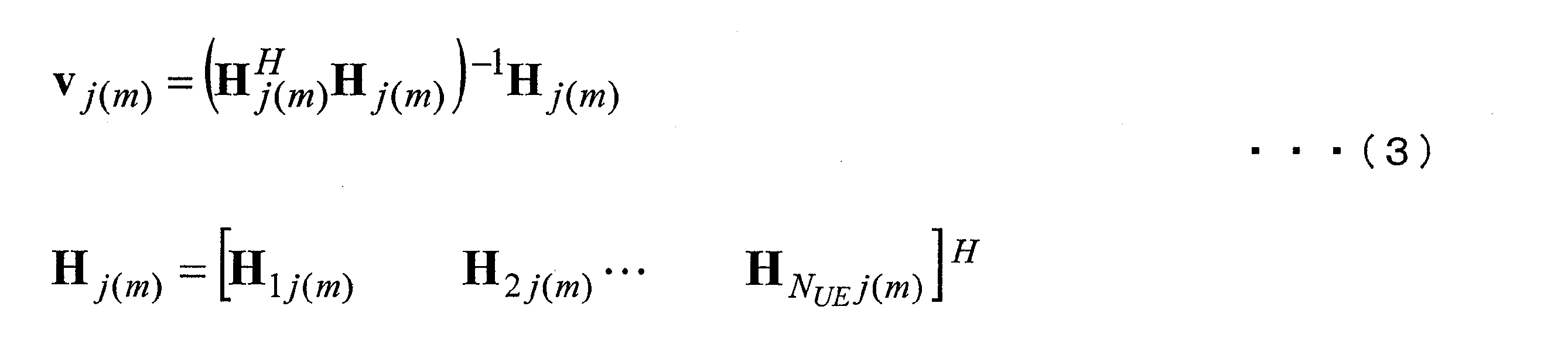
式(3)はZF(ゼロフォーシング;Zero Forcing)型の送信ウェイトであるが、他の送信ウェイトを用いてもよい。
<第1の実施形態の効果>
以上、例えば、各セルに3つのリソースブロックを割り当てる場合、従来技術では、セル間干渉の影響を考慮し、セル毎にリソース割り当てが重複しないように調整するため、マクロセルとピコセルで合計6つのリソースブロックが必要となる。しかし、本実施形態では、協調制御によってセル間干渉を抑圧することができるため、マクロセルとピコセルで同じリソースを割り当てることが可能となり、必要なリソースは3つのリソースブロックとなる。これにより、第1の実施形態の通信システムは、マルチセル環境において、複数のセルに同一のリソースが割り当てた場合において、セル間干渉を回避するために他のリソースに変更することが必要ないので、周波数利用効率を向上させることができる。
以上、例えば、各セルに3つのリソースブロックを割り当てる場合、従来技術では、セル間干渉の影響を考慮し、セル毎にリソース割り当てが重複しないように調整するため、マクロセルとピコセルで合計6つのリソースブロックが必要となる。しかし、本実施形態では、協調制御によってセル間干渉を抑圧することができるため、マクロセルとピコセルで同じリソースを割り当てることが可能となり、必要なリソースは3つのリソースブロックとなる。これにより、第1の実施形態の通信システムは、マルチセル環境において、複数のセルに同一のリソースが割り当てた場合において、セル間干渉を回避するために他のリソースに変更することが必要ないので、周波数利用効率を向上させることができる。
また、従来、基地局は、リソース割り当てが重複した端末を、セル間干渉を回避するために他のリソースに変更するため、全ての端末にとって最適なスケジューリングを行うことが困難となり、一部の端末装置では、スループットが劣化するという問題点があった。
本実施形態によれば、マルチセル環境において、マクロセル基地局は、複数のセルを同じリソースに割り当て、協調制御によってセル間干渉を抑えるので、端末装置は良好なスループットを得ることができる。
すなわち、第1の実施形態の通信システムは、マルチセル環境において、周波数利用効率を向上させつつ、良好なスループットを得ることができる。
本実施形態によれば、マルチセル環境において、マクロセル基地局は、複数のセルを同じリソースに割り当て、協調制御によってセル間干渉を抑えるので、端末装置は良好なスループットを得ることができる。
すなわち、第1の実施形態の通信システムは、マルチセル環境において、周波数利用効率を向上させつつ、良好なスループットを得ることができる。
[第2の実施形態]
第1の実施形態では、サブキャリア毎に算出した送受信ウェイトを用いて協調制御を行っていたが、本実施形態では複数のサブキャリア毎に一つの送受信ウェイトとする。以下では、第2の実施形態における構成について、第1の実施形態との相違点のみを説明する。ここで、一つの送受信ウェイトを算出するサブキャリア数をウェイト単位と定義し、本実施形態では、一例として、ウェイト単位を1リソースブロック(図1の例では12サブキャリア)とする。また、本実施形態では、一例として、端末がウェイト単位を決定する例とするが、基地局がウェイト単位を決定し制御してもよい。また、ウェイト単位は、システムで予め設定されていてもよい。
第1の実施形態では、サブキャリア毎に算出した送受信ウェイトを用いて協調制御を行っていたが、本実施形態では複数のサブキャリア毎に一つの送受信ウェイトとする。以下では、第2の実施形態における構成について、第1の実施形態との相違点のみを説明する。ここで、一つの送受信ウェイトを算出するサブキャリア数をウェイト単位と定義し、本実施形態では、一例として、ウェイト単位を1リソースブロック(図1の例では12サブキャリア)とする。また、本実施形態では、一例として、端末がウェイト単位を決定する例とするが、基地局がウェイト単位を決定し制御してもよい。また、ウェイト単位は、システムで予め設定されていてもよい。
図11は、第2の実施形態における通信システム1bの構成例を示す図である。
なお、図2と共通する要素には同一の符号を付し、その具体的な説明を省略する。
図11の通信システム1bの構成は、図2の通信システム1の構成に対して、マクロセル基地局100がマクロセル基地局(第一の基地局装置)100bに、マクロセル端末200-1がマクロセル端末200b-1に、ピコセル端末200b-2がピコセル端末200b-2に変更されたものとなっている。また、マクロセル11がマクロセル21へ変更され、ピコセル12がピコセル22に変更されたものとなっている。
なお、図2と共通する要素には同一の符号を付し、その具体的な説明を省略する。
図11の通信システム1bの構成は、図2の通信システム1の構成に対して、マクロセル基地局100がマクロセル基地局(第一の基地局装置)100bに、マクロセル端末200-1がマクロセル端末200b-1に、ピコセル端末200b-2がピコセル端末200b-2に変更されたものとなっている。また、マクロセル11がマクロセル21へ変更され、ピコセル12がピコセル22に変更されたものとなっている。
図12は、第2の実施形態における通信システムの処理の流れの一例を示すフローチャートである。ステップS301、S307、S309及びステップS310は、それぞれ図4のステップS101、S107、S109及びステップS110と同一であるので、その説明を省略する。以下、図12を用いて、第1の実施形態と異なる点について説明する。
ステップS302において、各端末(マクロセル端末200b-1及びピコセル端末200b-2)は自端末が接続している基地局へ、指定するウェイト単位毎の伝搬路情報及び受信品質を通知する。第2の実施形態では、一例としてウェイト単位が1リソースブロックであるため、伝搬路情報及び受信品質は、1リソースブロック毎に一つの値(以下、代表値ともいう)となる。第2の実施形態では、それぞれの情報のフィードバック数は6である。このとき、各端末は、例えばウェイト単位毎の伝搬路情報の平均値を伝搬路情報の代表値として算出することもできるし、参照信号が割り当てられているサブキャリアのうちの1つのサブキャリアにおける伝搬路情報を代表値として算出することもできる。また、各端末は、例えばウェイト単位毎の受信品質の平均値を受信品質の代表値として算出することもできるし、参照信号が割り当てられているサブキャリアのうちの1つのサブキャリアにおける受信品質を代表値として算出することもできる。また、伝搬路情報または受信品質の代表値のフィードバックは、端末が求めた代表値をフィードバックしてもよいし、別の情報、例えばコードブック、情報圧縮した値などをフィードバックしてもよい。またウェイト単位は、各端末で同じであってもよいし、異なっていてもよい。より詳細には、複数の端末装置のうち、少なくとも一つの端末装置のウェイト単位が他の端末装置のウェイト単位と異なっていてもよい。各端末でウェイト単位が同じである場合は、ウェイト単位を通知する情報量を減らすことができるため、伝送効率が向上する。一方、各端末でウェイト単位が異なる場合は、各端末で適した単位でウェイトを算出できるため、伝送性能を向上させることができる。
このように、第1の実施形態における各端末は、全てのサブキャリアにおける伝搬路情報と受信品質を自端末が接続している基地局へ通知していた。それに対し、第2の実施形態では、各端末は、指定するウェイト単位毎に一つの伝搬路情報及び一つの受信品質を自端末が接続している基地局へ通知するので、各端末から基地局への通信量(フィードバック量)を減らすことができる。さらにステップS302では、各端末は自端末が接続している基地局へウェイト単位を通知する。
ステップS303では、ピコセル基地局300は、有線ネットワークを用いて、ステップS302で取得した情報をマクロセル基地局100bへ通知する。なお、集中制御局以外の基地局が複数存在する場合には、それらの基地局が上記ステップS303の処理を行う。なお、ピコセル基地局300が、ピコセル端末装置200b-2から伝搬路情報の代表値を示す情報を通知された場合、以下の処理を行う。マクロセル基地局100b以外の基地局装置であるピコセル基地局300は、ピコセル端末装置200b-2から通知された伝搬路情報の代表値を示す情報を、有線ネットワークまたは無線ネットワーク経由でマクロセル基地局100bへ通知してもよい。
ステップS304において、マクロセル基地局100bは、各端末から通知されたウェイト単位毎の受信品質に基づいて、リソース割り当てを決定する。ここで、本実施形態におけるリソース割り当ては、第1の実施形態と同様に、RB1~RB3とする。
ステップS304において、マクロセル基地局100bは、各端末から通知されたウェイト単位毎の受信品質に基づいて、リソース割り当てを決定する。ここで、本実施形態におけるリソース割り当ては、第1の実施形態と同様に、RB1~RB3とする。
ステップS305において、マクロセル基地局100bは、ウェイト単位毎に送受信ウェイトを算出する。第1の実施形態では、サブキャリア毎の伝搬路情報に基づいて、割り当てられたリソース(RB1~RB3)に対してサブキャリア毎に送受信ウェイトを算出していた。それに対し、本実施形態では、各端末からフィードバックされた6つの伝搬路情報に基づいて、割り当てられたリソースに対してウェイト単位毎に送受信ウェイトを算出する。本実施形態では、一例としてマクロセル基地局100bは、3つの送受信ウェイトを算出する。なお、ステップS302で、端末装置は、参照信号を用いて、前記ウェイト単位の伝搬路情報の代表値を求めた場合、マクロセル基地局100bは、その伝搬路情報の代表値を用いてウェイト単位毎に送信ウェイト又は受信ウェイトを算出してもよい。また、マクロセル基地局100bは、伝搬路情報の代表値を用いてウェイト単位とは異なる単位毎に送信ウェイト又は受信ウェイトを算出してもよい。
また、ステップS306で通知する送受信ウェイト及びステップS308で通知する受信ウェイトは、それぞれ三つずつとなる。
また、ステップS306で通知する送受信ウェイト及びステップS308で通知する受信ウェイトは、それぞれ三つずつとなる。
図13は、第2の実施形態における端末装置200bの概略ブロック図である。
なお、図8と共通する要素には同一の符号を付し、その具体的な説明を省略する。図13の端末装置200bの構成は、図8の端末装置200の構成に対して、受信ウェイト乗算部243が受信ウェイト乗算部243bに、伝搬路推定部242が伝搬路推定部242bに、受信品質推定部251が受信品質推定部251bに変更されたものになっている。
なお、図8と共通する要素には同一の符号を付し、その具体的な説明を省略する。図13の端末装置200bの構成は、図8の端末装置200の構成に対して、受信ウェイト乗算部243が受信ウェイト乗算部243bに、伝搬路推定部242が伝搬路推定部242bに、受信品質推定部251が受信品質推定部251bに変更されたものになっている。
受信ウェイト乗算部243bは、第1の実施形態における受信ウェイト乗算部243と同様の機能を有するが、以下の点で異なる。
受信ウェイト乗算部243bは、信号分離部241から入力された受信データ信号に、ウェイト単位毎に同じ受信ウェイトを乗算する。具体的には、本実施形態の例の場合、リソースブロック1のサブキャリアではw=1の受信ウェイトを乗算し、リソースブロック2のサブキャリアではw=2の受信ウェイト、リソースブロック3のサブキャリアではw=3の受信ウェイトを乗算する。
受信ウェイト乗算部243bは、信号分離部241から入力された受信データ信号に、ウェイト単位毎に同じ受信ウェイトを乗算する。具体的には、本実施形態の例の場合、リソースブロック1のサブキャリアではw=1の受信ウェイトを乗算し、リソースブロック2のサブキャリアではw=2の受信ウェイト、リソースブロック3のサブキャリアではw=3の受信ウェイトを乗算する。
伝搬路推定部242bは、第1の実施形態における伝搬路推定部242と同様の機能を有するが、以下の点で異なる。
伝搬路推定部242bは、ウェイト単位毎に、伝搬路情報の代表値を算出する。具体的には、例えば、伝搬路推定部242bは、サブキャリア毎に伝搬路情報を推定する。そして、伝搬路推定部242bは、サブキャリア毎に算出された伝搬路情報をウェイト単位で平均し、その平均値を伝搬路情報の代表値として算出する。
伝搬路推定部242bは、ウェイト単位毎に、伝搬路情報の代表値を算出する。具体的には、例えば、伝搬路推定部242bは、サブキャリア毎に伝搬路情報を推定する。そして、伝搬路推定部242bは、サブキャリア毎に算出された伝搬路情報をウェイト単位で平均し、その平均値を伝搬路情報の代表値として算出する。
受信品質推定部251bは、第1の実施形態における受信品質推定部251と同様の機能を有するが、以下の点で異なる。
受信品質推定部251bは、ウェイト単位毎に、受信品質の代表値を算出する。具体的には、例えば、受信品質推定部251bは、サブキャリア毎に受信品質を推定する。そして、受信品質推定部251bは、サブキャリア毎に算出された受信品質をウェイト単位で平均し、その平均値を受信品質の代表値として算出する。
受信品質推定部251bは、ウェイト単位毎に、受信品質の代表値を算出する。具体的には、例えば、受信品質推定部251bは、サブキャリア毎に受信品質を推定する。そして、受信品質推定部251bは、サブキャリア毎に算出された受信品質をウェイト単位で平均し、その平均値を受信品質の代表値として算出する。
図14は、第2の実施形態におけるマクロセル基地局100bの概略ブロック図である。なお、図5と共通する要素には同一の符号を付し、その具体的な説明を省略する。図14のマクロセル基地局100bの構成は、図5のマクロセル基地局100の構成に対して、受信部104が受信部104bに、送信ウェイト乗算部107が送信ウェイト乗算部107bに、上位層160が上位層160bに、変更されたものになっている。
受信部104bは、第1の実施形態の受信部104と同様の機能を有するが、以下の点で異なる。
受信部104bは、マクロセル端末200-1から送信された送信信号に含まれるウェイト単位を上位層160bへ出力する。
受信部104bは、マクロセル端末200-1から送信された送信信号に含まれるウェイト単位を上位層160bへ出力する。
送信ウェイト乗算部107bは、第1の実施形態の送信ウェイト乗算部107と同様の機能を有するが、以下の点で異なる。
送信ウェイト乗算部107bは、変調部106から入力された入力された送信ビット列に、ウェイト単位毎に同じ送信ウェイトを乗算する。
具体的には、本実施形態の例の場合、リソースブロック1のサブキャリアではw=1の送信ウェイトを乗算し、リソースブロック2のサブキャリアではw=2の送信ウェイト、リソースブロック3のサブキャリアではw=3の送信ウェイトを乗算する。
送信ウェイト乗算部107bは、変調部106から入力された入力された送信ビット列に、ウェイト単位毎に同じ送信ウェイトを乗算する。
具体的には、本実施形態の例の場合、リソースブロック1のサブキャリアではw=1の送信ウェイトを乗算し、リソースブロック2のサブキャリアではw=2の送信ウェイト、リソースブロック3のサブキャリアではw=3の送信ウェイトを乗算する。
図15は、第2の実施形態における上位層160bの概略ブロック図である。上位層160bは、割当部161bと、ウェイト算出部162bとを備える。
割当部161bは、各端末から通知されたウェイト単位毎の受信品質に基づいて、リソース割り当てを決定する。割当部161bは、決定したリソース割り当ての結果を示す割当結果をウェイト算出部162bへ出力する。
割当部161bは、各端末から通知されたウェイト単位毎の受信品質に基づいて、リソース割り当てを決定する。割当部161bは、決定したリソース割り当ての結果を示す割当結果をウェイト算出部162bへ出力する。
ウェイト算出部162bは、割当部161bから入力された割当結果から割り当てられたリソースを取得する。ウェイト算出部162bは、各端末からフィードバックされた6つの伝搬路情報に基づいて、割当部161bにより割り当てられたリソースに対してウェイト単位毎に送受信ウェイトを算出する。
ここで、第1の実施形態(図9)におけるサブキャリア番号m(1≦m≦サブキャリア数)について、本実施形態ではフィードバック番号w(1≦w≦フィードバック数)とし、第1の実施形態におけるHkj(m)等のインデックスmをフィードバック番号wに置き換える。
本実施形態における送受信ウェイトの算出処理の流れを、図16を用いて説明する。図16は、第2の実施形態における送受信ウェイト算出の処理の流れを示すフローチャートである。
まず、ステップS401において、ウェイト算出部162bは、フィードバック番号wを1に初期化する。
まず、ステップS401において、ウェイト算出部162bは、フィードバック番号wを1に初期化する。
次に、ステップS402において、ウェイト算出部162bは、フィードバック番号wがフィードバック数以下の間、ステップS403~S414の処理を繰り返し、ウェイト単位毎に送受信ウェイトを算出する。具体的には、ウェイト算出部162bは、フィードバック番号wがフィードバック数以下であるか否か判定する。フィードバック番号wがフィードバック数以下である場合(ステップS402 YES)、ウェイト算出部162bは、ステップS403へ遷移する。一方、フィードバック番号wがフィードバック数を超える場合(ステップS402 NO)、ウェイト算出部162bは、ステップS415へ遷移する。
図16のステップS403~S414は、それぞれ図9のステップS203~S214と同様な処理であり、先に述べたように、処理の対象となるインデックスが異なる。つまり、図9では、ウェイト算出部162はサブキャリア番号mに基づいて、サブキャリア毎に送受信ウェイトを算出した。図16では、ウェイト算出部162bはフィードバック番号wに基づいて、フィードバック単位(ウェイト単位)毎に送受信ウェイトを算出する。
図16のステップS415では、ステップS413で算出した送受信ウェイト(本実施形態では6つ)のうち、リソース割り当てに指定されたRB1~RB3の送受信ウェイトを抽出する。以上により、本フローチャートの処理を終了する。
<第2の実施形態の効果>
以上のようにして、本実施形態における、マクロセル基地局100bは、リソース割り当てに指定されたリソースブロックについて、ウェイト単位毎の送受信ウェイトを算出することができる。
これにより、第2の実施形態の通信システム1bは、第1の実施形態の効果に加えて、本実施形態では、端末装置200bは、端末装置200bから基地局にフィードバックする伝搬路情報と受信品質とをウェイト単位毎に算出するので、基地局へのフィードバック量を削減できる。
以上のようにして、本実施形態における、マクロセル基地局100bは、リソース割り当てに指定されたリソースブロックについて、ウェイト単位毎の送受信ウェイトを算出することができる。
これにより、第2の実施形態の通信システム1bは、第1の実施形態の効果に加えて、本実施形態では、端末装置200bは、端末装置200bから基地局にフィードバックする伝搬路情報と受信品質とをウェイト単位毎に算出するので、基地局へのフィードバック量を削減できる。
なお、本実施形態におけるウェイト単位は、1リソースブロック(12サブキャリア)としたが、リソースブロックの自然数倍と指定することも可能である。例えば、ウェイト単位を3リソースブロックと指定した場合、端末から基地局へのフィードバック数は2(フィードバックする伝搬路情報及び受信品質はそれぞれRB1~RB3の平均値、RB4~RB6の平均値)となり、集中制御局はRB1~RB3もしくはRB4~RB6のどちらかにリソース割り当てを行い、ウェイト算出部162bは、一つの送受信ウェイトを算出してもよい。
また、本実施形態におけるウェイト単位は、リソースブロック単位ではなく、サブキャリア数で指定してもよい。つまり、16サブキャリア毎のようなリソースブロックと異なるリソース単位で指定するといった、リソースの割当単位とフィードバックの制御単位を異なるような方法を用いても本発明の範囲を逸脱しない。さらに、周波数帯によってウェイト単位を変えてもよく、例えば、RB1~RB2では1リソースブロック単位、RB3~6では2リソースブロック単位と指定してもよい。すなわち、マクロセル基地局100bは、送信ウェイトと前記受信ウェイトを、リソースブロックの自然数倍の単位で算出してもよい。また、マクロセル基地局100bは、送信ウェイトと受信ウェイトを、複数の種類のリソースブロック単位で算出してもよく、w=1のウェイトは1リソースブロックに対するウェイト、w=2のウェイトは2リソースブロックに対するウェイトといったように、ウェイト毎にウェイト算出単位が変わってもよい。例えば、ウェイト算出単位は伝搬路の周波数選択性(例えば周波数相関)を考慮し、周波数選択性が少ない場合、つまり周波数相関が高い場合はウェイト算出単位を大きくし、周波数選択性が大きい、つまり周波数相関が低い場合はウェイト算出単位を小さくするといったように、ウェイト算出単位を変えれば、演算量削減及び伝送特性向上の観点から適したウェイト算出単位とすることができる。すなわち、マクロセル基地局100bは、予め決められた算出単位毎に送信ウェイトと受信ウェイトを算出すればよい。
また、端末装置200bが1リソースブロック毎に伝搬路情報をフィードバックし、マクロセル基地局100bが2リソースブロック毎に送受信ウェイトを求めるといった、フィードバック単位よりもウェイト算出単位が大きくなってもよい。この場合、算出するウェイト数が減ることによって、マクロセル基地局100bの演算量を削減でき、またマクロセル基地局100bが端末装置200bへウェイトを通知するための制御情報量を削減できる。一方、端末装置200bが2リソースブロック毎に伝搬路情報をフィードバックし、マクロセル基地局100bがフィードバック情報を補間し、1リソースブロック毎にウェイトを求めるといった、フィードバック単位よりもウェイト算出単位が小さくなっても良い。この場合、マクロセル基地局100bが算出するウェイト間隔が狭くなるため、実際の伝搬路とウェイトの誤差が小さくなり、伝送特性を向上させることができる。
また、本実施形態では、端末装置200bがウェイト単位を指定する例としたが、マクロセル基地局100bが指定してもよい。その場合、マクロセル基地局100bは、ウェイト単位を各基地局装置へ送信する。これにより、ウェイト単位は、各基地局装置からそれぞれが通信する各端末装置200bに通知される。
また、端末装置200bが1リソースブロック毎に伝搬路情報をフィードバックし、マクロセル基地局100bが2リソースブロック毎に送受信ウェイトを求めるといった、フィードバック単位よりもウェイト算出単位が大きくなってもよい。この場合、算出するウェイト数が減ることによって、マクロセル基地局100bの演算量を削減でき、またマクロセル基地局100bが端末装置200bへウェイトを通知するための制御情報量を削減できる。一方、端末装置200bが2リソースブロック毎に伝搬路情報をフィードバックし、マクロセル基地局100bがフィードバック情報を補間し、1リソースブロック毎にウェイトを求めるといった、フィードバック単位よりもウェイト算出単位が小さくなっても良い。この場合、マクロセル基地局100bが算出するウェイト間隔が狭くなるため、実際の伝搬路とウェイトの誤差が小さくなり、伝送特性を向上させることができる。
また、本実施形態では、端末装置200bがウェイト単位を指定する例としたが、マクロセル基地局100bが指定してもよい。その場合、マクロセル基地局100bは、ウェイト単位を各基地局装置へ送信する。これにより、ウェイト単位は、各基地局装置からそれぞれが通信する各端末装置200bに通知される。
[第3の実施形態]
第1及び第2の実施形態では、送受信ウェイトを算出する単位が送信ウェイトと受信ウェイトで同じであったが、第3の実施形態では、送信ウェイトは、指定したウェイト単位毎であり、受信ウェイトはウェイト単位に関係なくサブキャリア毎に算出する。なお、サブキャリア毎に算出することに限らず、端末装置は、ウェイト単位とは異なる単位で受信ウェイトを生成してもよい。
第1及び第2の実施形態では、送受信ウェイトを算出する単位が送信ウェイトと受信ウェイトで同じであったが、第3の実施形態では、送信ウェイトは、指定したウェイト単位毎であり、受信ウェイトはウェイト単位に関係なくサブキャリア毎に算出する。なお、サブキャリア毎に算出することに限らず、端末装置は、ウェイト単位とは異なる単位で受信ウェイトを生成してもよい。
図17は、第3の実施形態における通信システム1cの構成例を示す図である。なお、図2と共通する要素には同一の符号を付し、その具体的な説明を省略する。
図17の通信システム1cの構成は、図2の通信システム1の構成に対して、マクロセル基地局100がマクロセル基地局(第一の基地局装置)100cに変更され、マクロセル端末200-1がマクロセル端末200c-1に変更され、ピコセル端末200b-2がピコセル端末200c-2に変更されたものとなっている。
図17の通信システム1cの構成は、図2の通信システム1の構成に対して、マクロセル基地局100がマクロセル基地局(第一の基地局装置)100cに変更され、マクロセル端末200-1がマクロセル端末200c-1に変更され、ピコセル端末200b-2がピコセル端末200c-2に変更されたものとなっている。
以下では、本実施形態における構成について、第1及び第2の実施形態との相違点のみを説明する。図18は、第3の実施形態における通信システムの処理の流れの一例を示すフローチャートである。第3の実施形態における通信システム1cの処理の流れは、第1の実施形態における通信システム1の処理の流れと比べて、第3の実施形態のマクロセル基地局100cは、送信ウェイトのみを必要とする点で異なる。ステップS501~S504、S507及びS509は、それぞれ図4のステップS101~S104、S107、S109と同一であるので、その説明を省略する。以下、図18を用いて、第1の実施形態と異なる点について説明する。
ステップS505において、マクロセル基地局100cは、送信ウェイトとリソース割り当てを算出する。次に、ステップS506において、マクロセル基地局100cは、有線ネットワーク経由で、ステップS505で算出した送信ウェイトとリソース割り当てをピコセル基地局300へ通知する。つまり、マクロセル基地局100cは、各端末へステップS505で算出した受信ウェイトを通知しない。
また、ステップS510において、各端末は、接続する基地局から送信された信号を受信し、受信処理を行う。その際、各端末は、受信した信号に基づいて、受信ウェイトを算出する。そして、各端末は、受信データ信号に対して算出した受信ウェイトを乗算することで、送信信号を復元する。
また、ステップS510において、各端末は、接続する基地局から送信された信号を受信し、受信処理を行う。その際、各端末は、受信した信号に基づいて、受信ウェイトを算出する。そして、各端末は、受信データ信号に対して算出した受信ウェイトを乗算することで、送信信号を復元する。
なお、集中制御局以外の基地局が複数存在する場合には、マクロセル基地局100cは、有線ネットワーク経由で、ステップS105で算出した送信ウェイトとリソース割り当てをそれらの、集中制御局以外の基地局全てに通知する。
また、第1及び第2の実施形態において、図4のステップS108では、各基地局は接続する端末へ受信ウェイトを通知していたが、第3の実施形態では通知しない。
また、第1及び第2の実施形態において、図4のステップS108では、各基地局は接続する端末へ受信ウェイトを通知していたが、第3の実施形態では通知しない。
図19は、第3の実施形態におけるマクロセル基地局100cの概略ブロック図である。なお、図5と共通する要素には同一の符号を付し、その具体的な説明を省略する。
図19のマクロセル基地局100cの構成は、図5のマクロセル基地局100の構成に対して、上位層160が上位層160cに変更され、無線部141、…、14Nがそれぞれ無線部141-c、…、14N-cに変更されたものとなっている。
図19のマクロセル基地局100cの構成は、図5のマクロセル基地局100の構成に対して、上位層160が上位層160cに変更され、無線部141、…、14Nがそれぞれ無線部141-c、…、14N-cに変更されたものとなっている。
上位層160cは、第1の実施形態における上位層160と同様に機能を有するが、以下の点で異なる。上位層160cは、送信ウェイトとリソース割り当てを算出する。上位層160cは、受信ウェイトを算出せず、受信ウェイトを無線部141-c、…、14N-cへ出力しない。これにより、無線部141-c、…、14N-cは、受信ウェイトをマクロセル端末200-1に送信しない。
図20は、第3の実施形態における端末装置200cの概略ブロック図である。なお、図8と共通する要素には同一の符号を付し、その具体的な説明を省略する。
図20の端末装置200cの構成は、図8の端末装置200の構成に対して、受信ウェイト算出部247cが追加され、信号分離部241が信号分離部241cに変更され、伝搬路推定部242が伝搬路推定部242cへ変更され、受信ウェイト乗算部243が受信ウェイト乗算部243cに変更されたものとなっている。すなわち、第1及び第2の実施形態との相違点は、第3の実施形態では、受信ウェイト算出部247cが含まれることである。
図20の端末装置200cの構成は、図8の端末装置200の構成に対して、受信ウェイト算出部247cが追加され、信号分離部241が信号分離部241cに変更され、伝搬路推定部242が伝搬路推定部242cへ変更され、受信ウェイト乗算部243が受信ウェイト乗算部243cに変更されたものとなっている。すなわち、第1及び第2の実施形態との相違点は、第3の実施形態では、受信ウェイト算出部247cが含まれることである。
信号分離部241cは、入力された信号から参照信号(復調用参照信号及び伝搬路推定用参照信号)と制御情報を分離する。そして、信号分離部241cは、参照信号を伝搬路推定部242cへ出力する。また、信号分離部241cは、入力された信号から参照信号と制御情報とが分離された後に残った受信データ信号を受信ウェイト乗算部243cへ出力する。また、信号分離部241は、制御情報を受信ウェイト乗算部243c、復調部245c及び復号部246cへ出力する。
伝搬路推定部242cは、サブキャリア毎の等価伝搬路情報H”k(m)を算出し、算出したサブキャリア毎の等価伝搬路情報H”k(m)を受信ウェイト算出部247cへ出力する。
受信ウェイト算出部247cは、伝搬路推定部242cから入力されたサブキャリア毎の等価伝搬路情報H”k(m)に基づいて、例えば、次式(4)のように受信ウェイトを算出する。
受信ウェイト算出部247cは、伝搬路推定部242cから入力されたサブキャリア毎の等価伝搬路情報H”k(m)に基づいて、例えば、次式(4)のように受信ウェイトを算出する。

ここで、σk2は端末装置kにおける雑音の平均電力であり、Iは単位行列である。式(4)はMMSE(最小平均二乗誤差;Minimum Mean Square Error)規範に基づいた受信ウェイトであるが、他の受信ウェイトを用いてもよい。受信ウェイト算出部247cは、算出した受信ウェイトを受信ウェイト乗算部243cに出力する。
受信ウェイト乗算部243cは、信号分離部241から入力された受信データ信号に、受信ウェイト算出部247cから入力された受信ウェイトを乗算し、乗算により得られた信号を復調部245へ出力する。
受信ウェイト乗算部243cは、信号分離部241から入力された受信データ信号に、受信ウェイト算出部247cから入力された受信ウェイトを乗算し、乗算により得られた信号を復調部245へ出力する。
<第3の実施形態の効果>
以上により、本実施形態では、第1の実施形態における効果に加えて、各基地局から接続する端末への受信ウェイトの通知が不要となり、各基地局から端末への通信量を削減することができる。また、各端末は、自端末で推定した等価伝搬路に基づいて受信ウェイトを算出するため、伝搬路のフィードバック誤差等の影響を軽減することができる。
以上により、本実施形態では、第1の実施形態における効果に加えて、各基地局から接続する端末への受信ウェイトの通知が不要となり、各基地局から端末への通信量を削減することができる。また、各端末は、自端末で推定した等価伝搬路に基づいて受信ウェイトを算出するため、伝搬路のフィードバック誤差等の影響を軽減することができる。
なお、マクロセル基地局100cが送受信ウェイトをサブキャリア単位で算出し、受信ウェイトを端末に通知する際に、ウェイト単位に間引いて通知してもよい。これにより、マクロセル基地局100cは、受信ウェイトの通知量を削減することができる。
なお、受信ウェイトが通知された場合であっても、端末装置200cはサブキャリア単位でウェイトを算出することも可能である。これにより、端末装置200cが移動している等、マクロセル基地局100cがウェイトを算出した伝搬路と端末装置200cが受信したときの伝搬路で誤差が生じた場合に、この誤差の影響を軽減することができる。
また、第3の実施形態では、端末装置200cはサブキャリア単位でウェイトを算出していたが、本発明はこれに限らず、送信ウェイトの算出単位とは異なる単位で受信ウェイトを算出する場合も本発明に含まれる。例えば、マクロセル基地局100cが2リソースブロック毎に送信ウェイトを算出した場合、端末装置200cは1リソースブロック毎に受信ウェイトを算出してもよいし、3リソースブロック毎に受信ウェイトを算出してもよい。端末装置200cの受信ウェイト算出単位を大きくすれば演算量を削減することができるし、受信ウェイト算出単位を小さくすれば伝送特性を向上させることができる。
なお、受信ウェイトが通知された場合であっても、端末装置200cはサブキャリア単位でウェイトを算出することも可能である。これにより、端末装置200cが移動している等、マクロセル基地局100cがウェイトを算出した伝搬路と端末装置200cが受信したときの伝搬路で誤差が生じた場合に、この誤差の影響を軽減することができる。
また、第3の実施形態では、端末装置200cはサブキャリア単位でウェイトを算出していたが、本発明はこれに限らず、送信ウェイトの算出単位とは異なる単位で受信ウェイトを算出する場合も本発明に含まれる。例えば、マクロセル基地局100cが2リソースブロック毎に送信ウェイトを算出した場合、端末装置200cは1リソースブロック毎に受信ウェイトを算出してもよいし、3リソースブロック毎に受信ウェイトを算出してもよい。端末装置200cの受信ウェイト算出単位を大きくすれば演算量を削減することができるし、受信ウェイト算出単位を小さくすれば伝送特性を向上させることができる。
また、本実施形態の基地局及び端末装置の各処理を実行するためのプログラムをコンピュータ読み取り可能な記録媒体に記録して、当該記録媒体に記録されたプログラムをコンピュータシステムに読み込ませ、実行することにより、基地局及び端末装置における上述した種々の処理を行ってもよい。
なお、ここでいう「コンピュータシステム」とは、OSや周辺機器等のハードウェアを含むものであってもよい。また、「コンピュータシステム」は、WWWシステムを利用している場合であれば、ホームページ提供環境(あるいは表示環境)も含むものとする。また、「コンピュータ読み取り可能な記録媒体」とは、フレキシブルディスク、光磁気ディスク、ROM、フラッシュメモリ等の書き込み可能な不揮発性メモリ、CD-ROM等の可搬媒体、コンピュータシステムに内蔵されるハードディスク等の記憶装置のことをいう。
さらに「コンピュータ読み取り可能な記録媒体」とは、インターネット等のネットワークや電話回線等の通信回線を介してプログラムが送信された場合のサーバやクライアントとなるコンピュータシステム内部の揮発性メモリ(例えばDRAM(Dynamic Random Access Memory))のように、一定時間プログラムを保持しているものも含むものとする。また、上記プログラムは、このプログラムを記憶装置等に格納したコンピュータシステムから、伝送媒体を介して、あるいは、伝送媒体中の伝送波により他のコンピュータシステムに伝送されてもよい。ここで、プログラムを伝送する「伝送媒体」は、インターネット等のネットワーク(通信網)や電話回線等の通信回線(通信線)のように情報を伝送する機能を有する媒体のことをいう。また、上記プログラムは、前述した機能の一部を実現するためのものであっても良い。さらに、前述した機能をコンピュータシステムにすでに記録されているプログラムとの組み合わせで実現できるもの、いわゆる差分ファイル(差分プログラム)であっても良い。
以上、本発明の実施形態について図面を参照して詳述したが、具体的な構成はこの実施形態に限られるものではなく、図面に図示されている構成等については、これらに限定されるものではなく、本発明の効果を発揮する範囲内で適宜変更することが可能である。その他、本発明の要旨を逸脱しない限りにおいて適宜変更して実施することが可能である。
1、 1b、1c 通信システム
100、100b、100c マクロセル基地局(第一の基地局装置)
101 受信アンテナ
102 無線部
103 A/D変換部
104 受信部
105 符号部
106 変調部
107 送信ウェイト乗算部
108 復調用参照信号生成部
109 伝搬路推定用参照信号生成部
110 制御信号生成部
111 信号多重部
121、…、12N IFFT部
131、…、13N D/A変換部
141、…、14N、141-c、…、14N-c 無線部(送信部)
151、…、15N 送信アンテナ
160、160-2、160b、160c 上位層
161、161b 割当部
162、162b ウェイト算出部
200、200b、200c 端末装置
200-1、200b-1、200c-1 マクロセル端末
200-2、200b-2、200c-2 ピコセル端末
201、…、20N 受信アンテナ
211、…、21n 無線部
221、…、22N A/D変換部
231、…、23N FFT部
241、241c 信号分離部
242、242c 伝搬路推定部
243、243c 受信ウェイト乗算部
245 復調部
246 復号部
247c 受信ウェイト算出部
251 受信品質推定部
252 送信部
253 D/A変換部
254 無線部
255 送信アンテナ
300 ピコセル基地局
100、100b、100c マクロセル基地局(第一の基地局装置)
101 受信アンテナ
102 無線部
103 A/D変換部
104 受信部
105 符号部
106 変調部
107 送信ウェイト乗算部
108 復調用参照信号生成部
109 伝搬路推定用参照信号生成部
110 制御信号生成部
111 信号多重部
121、…、12N IFFT部
131、…、13N D/A変換部
141、…、14N、141-c、…、14N-c 無線部(送信部)
151、…、15N 送信アンテナ
160、160-2、160b、160c 上位層
161、161b 割当部
162、162b ウェイト算出部
200、200b、200c 端末装置
200-1、200b-1、200c-1 マクロセル端末
200-2、200b-2、200c-2 ピコセル端末
201、…、20N 受信アンテナ
211、…、21n 無線部
221、…、22N A/D変換部
231、…、23N FFT部
241、241c 信号分離部
242、242c 伝搬路推定部
243、243c 受信ウェイト乗算部
245 復調部
246 復号部
247c 受信ウェイト算出部
251 受信品質推定部
252 送信部
253 D/A変換部
254 無線部
255 送信アンテナ
300 ピコセル基地局
Claims (29)
- 基地局装置と少なくとも一つの端末装置とが複数のリソースを用いて通信を行う通信エリアが複数存在し、前記複数の通信エリアが隣接または重複し合う通信システムであって、
前記複数の通信エリアのうち一つの通信エリアにおける基地局である第一の基地局装置は、前記複数のリソースのうち同じリソースに割り当てられている前記端末装置に対する前記複数の基地局装置における送信ウェイトを算出し、各基地局装置は通知された前記送信ウェイトが乗算された信号を前記端末装置へ送信することを特徴とする通信システム。 - 前記第一の基地局装置は、前記端末装置それぞれにおける受信ウェイトを更に算出し、前記端末装置はそれぞれ前記受信ウェイトを用いて復調することを特徴とする請求項1に記載の通信システム。
- 前記第一の基地局装置は、ウェイト算出の単位であるウェイト単位で前記送信ウェイトを算出することを特徴とする請求項1または2に記載の通信システム。
- 前記第一の基地局装置は、ウェイト算出の単位であるウェイト単位で前記送信ウェイト及び前記受信ウェイトを算出することを特徴とする請求項2に記載の通信システム。
- 前記ウェイト単位は、前記端末装置から前記各基地局装置に通知されることを特徴とする請求項3または4に記載の通信システム。
- 前記ウェイト単位は、前記各基地局装置から前記端末装置に通知されることを特徴とする請求項3または4に記載の通信システム。
- 前記端末装置は、参照信号を用いて、前記ウェイト単位の伝搬路情報の代表値を求め、該求めた伝搬路情報の代表値を示す情報を前記基地局装置に通知することを特徴とする請求項3から6のいずれか一項に記載の通信システム。
- 前記伝搬路情報の代表値は、前記ウェイト単位の平均値であることを特徴とする請求項
7に記載の通信システム。 - 前記伝搬路情報の代表値は、前記ウェイト単位のうち、前記参照信号が割り当てられて
いるサブキャリアの伝搬路情報であることを特徴とする請求項7に記載の通信システム。 - 前記第一の基地局装置は、前記伝搬路情報の代表値を用いて前記ウェイト単位毎に前記送信ウェイトを算出することを特徴とする請求項7に記載の通信システム。
- 前記第一の基地局装置は、前記伝搬路情報の代表値を用いて前記ウェイト単位毎に前記
送信ウェイト又は前記受信ウェイトを算出することを特徴とする請求項7に記載の通信システム。 - 前記第一の基地局装置は、前記伝搬路情報の代表値を用いて前記ウェイト単位とは異な
る単位毎に前記送信ウェイトを算出することを特徴とする請求項7に記載の通信システム。 - 前記第一の基地局装置は、前記伝搬路情報の代表値を用いて前記ウェイト単位とは異な
る単位毎に前記送信ウェイト又は前記受信ウェイトを算出することを特徴とする請求項7に記載の通信システム。 - 前記送信ウェイトの算出単位と前記受信ウェイトの算出単位は異なることを特徴とする
請求項13に記載の通信システム。 - 前記ウェイト単位は、サブキャリア単位であることを特徴とする請求項3から11のいずれか一項に記載の通信システム。
- 前記ウェイト単位は、リソースブロックの自然数倍の単位であることを特徴とする請求項3から11のいずれか一項に記載の通信システム。
- 前記ウェイト単位は、複数の種類のリソースブロック単位であることを特徴とする請求項3から11のいずれか一項に記載の通信システム。
- 前記複数の端末装置のうち、少なくとも一つの端末装置の前記ウェイト単位が他の端末装置のウェイト単位と異なることを特徴とする請求項3から17のいずれか一項に記載の通信システム。
- 前記端末装置は、前記ウェイト単位で受信ウェイトを生成することを特徴とする請求項
3から18のいずれか一項に記載の通信システム。 - 前記端末装置は、前記ウェイト単位とは異なる単位で受信ウェイトを生成することを特
徴とする請求項3から18のいずれか一項に記載の通信システム。 - 前記端末装置は、サブキャリア単位で受信ウェイトを生成することを特徴とする請求項
1から18のいずれか一項に記載の通信システム。 - 前記複数の通信エリアそれぞれにおける基地局装置は有線ネットワークまたは無線ネットワークで相互に接続されており、
前記第一の基地局装置以外の基地局装置は、前記端末装置から通知された前記伝搬路情
報の代表値を示す情報を、前記有線ネットワークまたは無線ネットワーク経由で前記第一の基地局装置へ通知することを特徴とする請求項1から21のいずれか一項に記載の通信システム。 - 前記複数の通信エリアそれぞれにおける基地局装置は有線ネットワークまたは無線ネットワークで相互に接続されており、
前記第一の基地局装置は、前記求めた送信ウェイトを、前記有線または無線ネットワー
ク経由で他の基地局装置へ通知することを特徴とする請求項1から22のいずれか一項に記載の通信システム。 - 前記第一の基地局装置は、更に前記求めた受信ウェイトを、前記有線または無線ネットワーク経由で他の基地局装置へ通知することを特徴とする請求項23に記載の通信システム。
- 基地局装置と少なくとも一つの端末装置とが通信を行う通信エリアが複数存在し、前記複数の通信エリアが隣接または重複し合う通信システムにおける通信方法であって、
前記複数の通信エリアのうち1つの通信エリアにおける基地局である第一の基地局装置は、前記協調する基地局装置における送信ウェイトを算出して、該送信ウェイトを示す情報を各基地局装置に通知する手順と、
各基地局装置は通知された前記送信ウェイトが乗算された信号を前記端末装置へ送信する手順と、
を有することを特徴とする通信方法。 - 各セルの受信品質に基づいて、通信に使用する同じリソースを割り当てる割当部と、
前記割当部が同じリソースに割り当てた端末に対してセル間干渉の抑圧を行う送信ウェイトを算出するウェイト算出部と、
送信信号に前記ウェイト算出部が算出した送信ウェイトを乗算する送信ウェイト乗算部と、
前記送信ウェイト乗算部が乗算することにより得られた信号を通信エリア内の端末装置へ送信する送信部と、
を備えることを特徴とする基地局装置。 - 前記ウェイト算出部は、前記端末装置がセル間干渉を抑圧するための受信ウェイトを更に算出し、
前記送信部は、該算出した受信ウェイトを示す情報を通信エリア内の端末装置へ通知することを特徴とする請求項26に記載の基地局装置。 - 基地局装置から送信された送信信号から、受信データ信号と受信ウェイトとに分離する信号分離部と、
前記信号分離部が分離した受信データ信号に前記信号分離部が分離した受信ウェイトを乗算する受信ウェイト乗算部と、
を備えることを特徴とする端末装置。 - 基地局装置から送信された送信信号から、参照信号と制御情報とに分離する信号分離部と、
前記信号分離部が分離した参照信号に基づいて、サブキャリア毎の等価伝搬路を推定する伝搬路推定部と、
前記伝搬路推定部が推定したサブキャリア毎の等価伝搬路に基づいて、受信ウェイトを算出する受信ウェイト算出部と、
前記信号分離部が分離した制御情報に前記受信ウェイト算出部が算出した受信ウェイトを乗算する受信ウェイト乗算部と、
を備えることを特徴とする端末装置。
Priority Applications (1)
| Application Number | Priority Date | Filing Date | Title |
|---|---|---|---|
| US14/385,248 US20150023317A1 (en) | 2012-03-16 | 2013-03-11 | Communication system, communication method, base station apparatus, and terminal apparatus |
Applications Claiming Priority (2)
| Application Number | Priority Date | Filing Date | Title |
|---|---|---|---|
| JP2012-060736 | 2012-03-16 | ||
| JP2012060736A JP5923786B2 (ja) | 2012-03-16 | 2012-03-16 | 基地局装置及び通信方法 |
Publications (1)
| Publication Number | Publication Date |
|---|---|
| WO2013137166A1 true WO2013137166A1 (ja) | 2013-09-19 |
Family
ID=49161075
Family Applications (1)
| Application Number | Title | Priority Date | Filing Date |
|---|---|---|---|
| PCT/JP2013/056583 Ceased WO2013137166A1 (ja) | 2012-03-16 | 2013-03-11 | 通信システム、通信方法、基地局装置及び端末装置 |
Country Status (3)
| Country | Link |
|---|---|
| US (1) | US20150023317A1 (ja) |
| JP (1) | JP5923786B2 (ja) |
| WO (1) | WO2013137166A1 (ja) |
Families Citing this family (7)
| Publication number | Priority date | Publication date | Assignee | Title |
|---|---|---|---|---|
| US9668245B2 (en) | 2011-04-29 | 2017-05-30 | Nokia Solutions And Networks Oy | Method and device for processing uplink control data in a wireless network |
| KR102244366B1 (ko) | 2014-05-09 | 2021-04-26 | 삼성전자주식회사 | 무선통신 시스템에서 간섭 신호 제거 및 억제를 위한 무선 자원 활용 방법 및 장치 |
| WO2016056462A1 (ja) * | 2014-10-07 | 2016-04-14 | 三菱電機株式会社 | 無線通信装置および無線通信方法 |
| JPWO2016185968A1 (ja) * | 2015-05-15 | 2018-04-05 | 京セラ株式会社 | 通信装置 |
| CN106953676A (zh) | 2016-01-07 | 2017-07-14 | 索尼公司 | 无线通信方法和无线通信设备 |
| KR102901025B1 (ko) * | 2016-09-19 | 2025-12-18 | 삼성전자 주식회사 | 이동 통신 시스템에서의 기준 신호, 제어 신호 및 데이터 송신 방법 및 장치 |
| EP3606262B1 (en) * | 2017-04-12 | 2021-07-28 | Huawei Technologies Co., Ltd. | Method, device and system for determining scheduling user |
Citations (3)
| Publication number | Priority date | Publication date | Assignee | Title |
|---|---|---|---|---|
| JP2005065242A (ja) * | 2003-07-28 | 2005-03-10 | Matsushita Electric Ind Co Ltd | 無線通信装置および無線通信方法 |
| JP2007019880A (ja) * | 2005-07-07 | 2007-01-25 | Matsushita Electric Ind Co Ltd | 通信装置、基地局装置及び通信方法 |
| JP2011082709A (ja) * | 2009-10-05 | 2011-04-21 | Ntt Docomo Inc | 無線基地局装置、移動端末装置及び無線通信方法 |
Family Cites Families (28)
| Publication number | Priority date | Publication date | Assignee | Title |
|---|---|---|---|---|
| WO2007063438A2 (en) * | 2005-11-02 | 2007-06-07 | Pallasium Ltd. | Interference cancellation in sector antenna |
| KR100705501B1 (ko) * | 2005-11-16 | 2007-04-09 | 한국전자통신연구원 | 이동통신 시스템 기지국의 공간분할 다중화에 의한하향링크/상향링크 스케쥴링 및 자원 할당 방법 |
| KR101154992B1 (ko) * | 2006-04-24 | 2012-06-14 | 엘지전자 주식회사 | 다중 사용자 시스템에 적용되는 신호 수신 방법 |
| CN101127747B (zh) * | 2006-08-14 | 2010-09-08 | 大唐移动通信设备有限公司 | 一种时分双工复用系统中实现频域调度的方法及系统 |
| KR100753369B1 (ko) * | 2006-08-30 | 2007-08-30 | 주식회사 팬택 | 이동통신 시스템의 셀간 간섭을 저감하는 방법 |
| WO2008032358A1 (en) * | 2006-09-11 | 2008-03-20 | Fujitsu Limited | Radio communication apparatus and radio communication method |
| US8279960B2 (en) * | 2007-05-23 | 2012-10-02 | Samsung Electronics Co., Ltd. | Multiple-input multiple-output communication method and multiple-input multiple-output communication system of enabling the method |
| US8798183B2 (en) * | 2007-08-13 | 2014-08-05 | Qualcomm Incorporated | Feedback and rate adaptation for MIMO transmission in a time division duplexed (TDD) communication system |
| KR101399029B1 (ko) * | 2007-09-12 | 2014-06-27 | 삼성전자주식회사 | 무선통신시스템에서 파일럿을 전송하기 위한 장치 및 방법 |
| US7933350B2 (en) * | 2007-10-30 | 2011-04-26 | Telefonaktiebolaget Lm Ericsson (Publ) | Channel-dependent frequency-domain scheduling in an orthogonal frequency division multiplexing communications system |
| KR101443630B1 (ko) * | 2007-11-09 | 2014-09-23 | 엘지전자 주식회사 | 기본 신호 할당 단위 설정 방법 및 이를 이용한 신호 전송방법 |
| JP5233331B2 (ja) * | 2008-03-12 | 2013-07-10 | 富士通株式会社 | 無線基地局、無線端末及び無線通信方法 |
| ATE546891T1 (de) * | 2008-06-18 | 2012-03-15 | Ericsson Telefon Ab L M | Verringerung von störungen zwischen zellen |
| US8254318B2 (en) * | 2008-07-11 | 2012-08-28 | Alcatel Lucent | Wireless communication system and method of joint beamforming wireless communication |
| US8830926B2 (en) * | 2008-10-27 | 2014-09-09 | Nokia Siemens Networks Oy | Method for network co-ordination in a mobile communications system and apparatus thereof |
| KR101591848B1 (ko) * | 2009-03-26 | 2016-02-04 | 삼성전자주식회사 | 이동통신 시스템에서 자원 할당을 위한 장치 및 방법 |
| KR101607988B1 (ko) * | 2009-04-23 | 2016-04-12 | 삼성전자주식회사 | 무선통신시스템에서 간섭 완화를 위한 장치 및 방법 |
| CN101877609B (zh) * | 2009-04-30 | 2013-06-12 | 富士通株式会社 | 通信装置、基站和多点合作通信方法 |
| US8738065B2 (en) * | 2009-10-02 | 2014-05-27 | Kyocera Corporation | Radio communication system, large cell base station, and communication control method |
| US9014149B2 (en) * | 2010-01-22 | 2015-04-21 | Sumitomo Electric Industries, Ltd. | Communication apparatus and base station apparatus |
| US8305987B2 (en) * | 2010-02-12 | 2012-11-06 | Research In Motion Limited | Reference signal for a coordinated multi-point network implementation |
| JP2012015963A (ja) * | 2010-07-05 | 2012-01-19 | Sharp Corp | 端末装置、基地局装置及びそれらを用いた無線通信システム |
| WO2012026601A1 (ja) * | 2010-08-27 | 2012-03-01 | 京セラ株式会社 | 無線基地局及び通信制御方法 |
| US8797959B2 (en) * | 2011-01-05 | 2014-08-05 | Futurewei Technologies, Inc. | System and method for transceiver design |
| KR101585422B1 (ko) * | 2011-01-31 | 2016-01-25 | 삼성전자주식회사 | 무선통신 시스템에서 셀 간 제한적 협력을 통한 프리코딩 장치 및 방법 |
| KR101197867B1 (ko) * | 2011-02-08 | 2012-11-05 | 고려대학교 산학협력단 | 빔 포밍 방법 및 이를 이용한 다중 안테나 시스템 |
| JP5897810B2 (ja) * | 2011-03-29 | 2016-03-30 | シャープ株式会社 | 基地局装置、端末装置、通信システム、通信方法 |
| JP5905240B2 (ja) * | 2011-11-02 | 2016-04-20 | シャープ株式会社 | アクセスポイント |
-
2012
- 2012-03-16 JP JP2012060736A patent/JP5923786B2/ja not_active Expired - Fee Related
-
2013
- 2013-03-11 US US14/385,248 patent/US20150023317A1/en not_active Abandoned
- 2013-03-11 WO PCT/JP2013/056583 patent/WO2013137166A1/ja not_active Ceased
Patent Citations (3)
| Publication number | Priority date | Publication date | Assignee | Title |
|---|---|---|---|---|
| JP2005065242A (ja) * | 2003-07-28 | 2005-03-10 | Matsushita Electric Ind Co Ltd | 無線通信装置および無線通信方法 |
| JP2007019880A (ja) * | 2005-07-07 | 2007-01-25 | Matsushita Electric Ind Co Ltd | 通信装置、基地局装置及び通信方法 |
| JP2011082709A (ja) * | 2009-10-05 | 2011-04-21 | Ntt Docomo Inc | 無線基地局装置、移動端末装置及び無線通信方法 |
Non-Patent Citations (1)
| Title |
|---|
| HUAWEI ET AL.: "TP for 3GPP TR36.814 on CoMP", 3GPP TSG-RAN WG1 #60 R1-101695, 26 February 2010 (2010-02-26), pages 1 - 6, Retrieved from the Internet <URL:http://www.3gpp.org/ftp/tsg_ran/WG1RL1/TSGR160/Docs/R1-101695.zip> * |
Also Published As
| Publication number | Publication date |
|---|---|
| US20150023317A1 (en) | 2015-01-22 |
| JP2013197710A (ja) | 2013-09-30 |
| JP5923786B2 (ja) | 2016-05-25 |
Similar Documents
| Publication | Publication Date | Title |
|---|---|---|
| AU2025230741B2 (en) | Systems and methods for radio frequency calibration exploiting channel reciprocity in distributed input distributed output wireless communications | |
| JP5923786B2 (ja) | 基地局装置及び通信方法 | |
| CN103404060B (zh) | 终端装置、反馈控制方法、基站、配对控制方法和无线通信系统 | |
| CN105723688B (zh) | 用于无线连网的方法和装置 | |
| CN104079332B (zh) | 实现协作多点传输与多用户多输入多输出的通讯方法 | |
| KR20110063584A (ko) | 다중 셀 협력적 무선통신 시스템에서 데이터를 전송하는 방법 | |
| WO2012077791A1 (ja) | 無線中継局装置、無線基地局装置及び無線通信方法 | |
| KR20160062731A (ko) | 분산 어레이 매시브 mimo 시스템의 신호 송수신 방법 및 장치 | |
| JP5897810B2 (ja) | 基地局装置、端末装置、通信システム、通信方法 | |
| WO2013042496A1 (ja) | 無線通信システムおよび無線通信方法ならびに基地局装置 | |
| EP3058767B1 (en) | Interference alignment for transmitter/receiver pairs in wireless communication systems | |
| US10425701B2 (en) | Filter reuse method for transmitting and receiving filter bank-based multicarrier signals | |
| WO2013099746A1 (ja) | 基地局装置、許容重複数決定方法、許容重複数決定プログラム、移動局装置、許容重複数通知方法及び許容重複数通知プログラム | |
| CN106160822B (zh) | 一种协作波束赋形方法和基站 | |
| KR20130102326A (ko) | 분산 소형 기지국을 포함하는 이동 통신시스템에서의 데이터 송수신 장치 및 방법 | |
| CN108322271B (zh) | 基于负载的以用户为中心的动态分簇方法 | |
| CN103348616A (zh) | 终端设备、反馈控制方法、基站、配对控制方法、程序和无线通信系统 | |
| JP2013243454A (ja) | 通信システム及び通信方法 | |
| JP5468577B2 (ja) | 無線通信システムおよび無線通信方法 | |
| JPWO2016021012A1 (ja) | 無線通信システム、基地局、移動局、送信方法および復調方法 | |
| JP2016154304A (ja) | 制御装置、協調パターン選択方法、及び無線通信システム | |
| KR102263034B1 (ko) | 무선 통신 시스템의 하향링크 신호 전송 방법 | |
| Do et al. | Joint of full-duplex relay, non-linear energy harvesting and multiple access in performance improvement of cell-edge user in heterogeneous networks | |
| Chen et al. | A novel interference suppression method in wireless relay networks | |
| CN103096330A (zh) | 一种基于mu-mimo优化用户设备调度的方法和设备 |
Legal Events
| Date | Code | Title | Description |
|---|---|---|---|
| 121 | Ep: the epo has been informed by wipo that ep was designated in this application |
Ref document number: 13761639 Country of ref document: EP Kind code of ref document: A1 |
|
| WWE | Wipo information: entry into national phase |
Ref document number: 14385248 Country of ref document: US |
|
| NENP | Non-entry into the national phase |
Ref country code: DE |
|
| 122 | Ep: pct application non-entry in european phase |
Ref document number: 13761639 Country of ref document: EP Kind code of ref document: A1 |