WO2013136868A1 - Four de gazéification à circulation - Google Patents
Four de gazéification à circulation Download PDFInfo
- Publication number
- WO2013136868A1 WO2013136868A1 PCT/JP2013/052274 JP2013052274W WO2013136868A1 WO 2013136868 A1 WO2013136868 A1 WO 2013136868A1 JP 2013052274 W JP2013052274 W JP 2013052274W WO 2013136868 A1 WO2013136868 A1 WO 2013136868A1
- Authority
- WO
- WIPO (PCT)
- Prior art keywords
- gasification
- furnace
- residue
- raw material
- gasification furnace
- Prior art date
Links
Images


Classifications
-
- C—CHEMISTRY; METALLURGY
- C10—PETROLEUM, GAS OR COKE INDUSTRIES; TECHNICAL GASES CONTAINING CARBON MONOXIDE; FUELS; LUBRICANTS; PEAT
- C10B—DESTRUCTIVE DISTILLATION OF CARBONACEOUS MATERIALS FOR PRODUCTION OF GAS, COKE, TAR, OR SIMILAR MATERIALS
- C10B49/00—Destructive distillation of solid carbonaceous materials by direct heating with heat-carrying agents including the partial combustion of the solid material to be treated
- C10B49/02—Destructive distillation of solid carbonaceous materials by direct heating with heat-carrying agents including the partial combustion of the solid material to be treated with hot gases or vapours, e.g. hot gases obtained by partial combustion of the charge
- C10B49/04—Destructive distillation of solid carbonaceous materials by direct heating with heat-carrying agents including the partial combustion of the solid material to be treated with hot gases or vapours, e.g. hot gases obtained by partial combustion of the charge while moving the solid material to be treated
- C10B49/08—Destructive distillation of solid carbonaceous materials by direct heating with heat-carrying agents including the partial combustion of the solid material to be treated with hot gases or vapours, e.g. hot gases obtained by partial combustion of the charge while moving the solid material to be treated in dispersed form
- C10B49/10—Destructive distillation of solid carbonaceous materials by direct heating with heat-carrying agents including the partial combustion of the solid material to be treated with hot gases or vapours, e.g. hot gases obtained by partial combustion of the charge while moving the solid material to be treated in dispersed form according to the "fluidised bed" technique
-
- C—CHEMISTRY; METALLURGY
- C10—PETROLEUM, GAS OR COKE INDUSTRIES; TECHNICAL GASES CONTAINING CARBON MONOXIDE; FUELS; LUBRICANTS; PEAT
- C10J—PRODUCTION OF PRODUCER GAS, WATER-GAS, SYNTHESIS GAS FROM SOLID CARBONACEOUS MATERIAL, OR MIXTURES CONTAINING THESE GASES; CARBURETTING AIR OR OTHER GASES
- C10J3/00—Production of combustible gases containing carbon monoxide from solid carbonaceous fuels
- C10J3/46—Gasification of granular or pulverulent flues in suspension
- C10J3/48—Apparatus; Plants
- C10J3/482—Gasifiers with stationary fluidised bed
-
- C—CHEMISTRY; METALLURGY
- C10—PETROLEUM, GAS OR COKE INDUSTRIES; TECHNICAL GASES CONTAINING CARBON MONOXIDE; FUELS; LUBRICANTS; PEAT
- C10J—PRODUCTION OF PRODUCER GAS, WATER-GAS, SYNTHESIS GAS FROM SOLID CARBONACEOUS MATERIAL, OR MIXTURES CONTAINING THESE GASES; CARBURETTING AIR OR OTHER GASES
- C10J2300/00—Details of gasification processes
- C10J2300/09—Details of the feed, e.g. feeding of spent catalyst, inert gas or halogens
- C10J2300/0913—Carbonaceous raw material
- C10J2300/0916—Biomass
-
- C—CHEMISTRY; METALLURGY
- C10—PETROLEUM, GAS OR COKE INDUSTRIES; TECHNICAL GASES CONTAINING CARBON MONOXIDE; FUELS; LUBRICANTS; PEAT
- C10J—PRODUCTION OF PRODUCER GAS, WATER-GAS, SYNTHESIS GAS FROM SOLID CARBONACEOUS MATERIAL, OR MIXTURES CONTAINING THESE GASES; CARBURETTING AIR OR OTHER GASES
- C10J2300/00—Details of gasification processes
- C10J2300/09—Details of the feed, e.g. feeding of spent catalyst, inert gas or halogens
- C10J2300/0913—Carbonaceous raw material
- C10J2300/093—Coal
-
- C—CHEMISTRY; METALLURGY
- C10—PETROLEUM, GAS OR COKE INDUSTRIES; TECHNICAL GASES CONTAINING CARBON MONOXIDE; FUELS; LUBRICANTS; PEAT
- C10J—PRODUCTION OF PRODUCER GAS, WATER-GAS, SYNTHESIS GAS FROM SOLID CARBONACEOUS MATERIAL, OR MIXTURES CONTAINING THESE GASES; CARBURETTING AIR OR OTHER GASES
- C10J2300/00—Details of gasification processes
- C10J2300/09—Details of the feed, e.g. feeding of spent catalyst, inert gas or halogens
- C10J2300/0913—Carbonaceous raw material
- C10J2300/0946—Waste, e.g. MSW, tires, glass, tar sand, peat, paper, lignite, oil shale
-
- C—CHEMISTRY; METALLURGY
- C10—PETROLEUM, GAS OR COKE INDUSTRIES; TECHNICAL GASES CONTAINING CARBON MONOXIDE; FUELS; LUBRICANTS; PEAT
- C10J—PRODUCTION OF PRODUCER GAS, WATER-GAS, SYNTHESIS GAS FROM SOLID CARBONACEOUS MATERIAL, OR MIXTURES CONTAINING THESE GASES; CARBURETTING AIR OR OTHER GASES
- C10J2300/00—Details of gasification processes
- C10J2300/09—Details of the feed, e.g. feeding of spent catalyst, inert gas or halogens
- C10J2300/0953—Gasifying agents
- C10J2300/0973—Water
- C10J2300/0976—Water as steam
-
- C—CHEMISTRY; METALLURGY
- C10—PETROLEUM, GAS OR COKE INDUSTRIES; TECHNICAL GASES CONTAINING CARBON MONOXIDE; FUELS; LUBRICANTS; PEAT
- C10J—PRODUCTION OF PRODUCER GAS, WATER-GAS, SYNTHESIS GAS FROM SOLID CARBONACEOUS MATERIAL, OR MIXTURES CONTAINING THESE GASES; CARBURETTING AIR OR OTHER GASES
- C10J2300/00—Details of gasification processes
- C10J2300/09—Details of the feed, e.g. feeding of spent catalyst, inert gas or halogens
- C10J2300/0983—Additives
- C10J2300/0993—Inert particles, e.g. as heat exchange medium in a fluidized or moving bed, heat carriers, sand
-
- C—CHEMISTRY; METALLURGY
- C10—PETROLEUM, GAS OR COKE INDUSTRIES; TECHNICAL GASES CONTAINING CARBON MONOXIDE; FUELS; LUBRICANTS; PEAT
- C10J—PRODUCTION OF PRODUCER GAS, WATER-GAS, SYNTHESIS GAS FROM SOLID CARBONACEOUS MATERIAL, OR MIXTURES CONTAINING THESE GASES; CARBURETTING AIR OR OTHER GASES
- C10J2300/00—Details of gasification processes
- C10J2300/16—Integration of gasification processes with another plant or parts within the plant
- C10J2300/1625—Integration of gasification processes with another plant or parts within the plant with solids treatment
- C10J2300/1637—Char combustion
-
- C—CHEMISTRY; METALLURGY
- C10—PETROLEUM, GAS OR COKE INDUSTRIES; TECHNICAL GASES CONTAINING CARBON MONOXIDE; FUELS; LUBRICANTS; PEAT
- C10J—PRODUCTION OF PRODUCER GAS, WATER-GAS, SYNTHESIS GAS FROM SOLID CARBONACEOUS MATERIAL, OR MIXTURES CONTAINING THESE GASES; CARBURETTING AIR OR OTHER GASES
- C10J2300/00—Details of gasification processes
- C10J2300/18—Details of the gasification process, e.g. loops, autothermal operation
- C10J2300/1807—Recycle loops, e.g. gas, solids, heating medium, water
-
- Y—GENERAL TAGGING OF NEW TECHNOLOGICAL DEVELOPMENTS; GENERAL TAGGING OF CROSS-SECTIONAL TECHNOLOGIES SPANNING OVER SEVERAL SECTIONS OF THE IPC; TECHNICAL SUBJECTS COVERED BY FORMER USPC CROSS-REFERENCE ART COLLECTIONS [XRACs] AND DIGESTS
- Y02—TECHNOLOGIES OR APPLICATIONS FOR MITIGATION OR ADAPTATION AGAINST CLIMATE CHANGE
- Y02E—REDUCTION OF GREENHOUSE GAS [GHG] EMISSIONS, RELATED TO ENERGY GENERATION, TRANSMISSION OR DISTRIBUTION
- Y02E20/00—Combustion technologies with mitigation potential
- Y02E20/16—Combined cycle power plant [CCPP], or combined cycle gas turbine [CCGT]
- Y02E20/18—Integrated gasification combined cycle [IGCC], e.g. combined with carbon capture and storage [CCS]
Definitions
- the present invention relates to a circulation type gasification furnace that gasifies a gasification raw material by circulating a fluid medium.
- coal in particular, has a recoverable period of about 150 years, more than three times the recoverable period of oil, and reserves are unevenly distributed compared to oil. Therefore, it is expected as a natural resource that can be stably supplied over a long period of time.
- the gasification process of coal has been performed by partial oxidation using oxygen or air, but in this gasification process, a high temperature of about 1800 ° C. and a high pressure of about 3 MPa, A pressure-resistant material is required, and the cost of the gasifier increases.
- a technology for gasifying coal using steam at a relatively low temperature of about 700 ° C. to 900 ° C. and normal pressure has been developed. This technology has advantages that a pressure-resistant structure is not required and that existing commercial products can be used by setting the temperature and pressure low.
- the above-described steam gasification reaction of the organic solid material requires a relatively long reaction time. Accordingly, in the gasification furnace, for example, a fluid medium such as sand having a high temperature of 800 ° C. or higher is supplied to the gasification furnace so that the residence time for sufficiently reacting the organic solid raw material is satisfied.
- the fluidized bed is formed by supplying water vapor from the bottom of the fluid.
- gasification raw material is produced
- the solid particles having a small particle size are scattered away from the fluidized bed together with the gasified gas.
- a gasification gas separator (cyclone) that separates the gasification gas and solid particles is installed at the outlet of the gasification furnace, and the solid particles collected by the gasification gas separator are collected. Can be returned to the gasification furnace (for example, Patent Document 1).
- the solid particles are once collected in the gasification gas separator and returned to the gasification furnace, the newly generated solid particles are scattered again in the gasification furnace, and the gasification gas The flow of separation by a separator is repeated. And anyway, it becomes a particle of small particle size and cannot be collected by the gasification gas separator, and it may reach the gas purification equipment at the subsequent stage together with the gasification gas, which may cause problems of the gas purification equipment etc. is there.
- the present invention suppresses repeated scattering of solid particles in the gasification furnace while maintaining the utilization efficiency of the gasification raw material, and appropriately gasifies the gasification gas in the gasification gas separator. It aims at providing the circulation type gasification furnace which can derive
- a circulating gasification furnace gasifies a fluidized medium into a fluidized bed or a moving bed, and gasifies the gasification raw material put into the fluidized medium with the heat of the fluidized medium.
- the medium separator for separating the fluidized medium derived from the combustion furnace and the combustion exhaust gas, the gasification gas generated in the gasification furnace and the residue of the gasification raw material are separated, and the gasification gas is derived.
- a gasification gas separator; and a residue derivation unit that guides the residue separated by the gasification gas separator to the combustion furnace while sealing the gasification gas separator and the combustion furnace.
- the residue deriving unit may be configured by a loop seal that seals gases with a liquid or a solid interposed therebetween.
- the residue deriving unit may be constituted by a screw feeder that rotates a helical screw and feeds the residue of the gasification raw material in the direction of the rotation axis.
- the present invention while maintaining the utilization efficiency of the gasification raw material, it is possible to suppress the solid particles from being repeatedly scattered in the gasification furnace and appropriately derive the gasification gas in the gasification gas separator. It becomes.
- FIG. 1 is a diagram for explaining a schematic configuration of a circulating fluidized bed gasification furnace 100.
- a circulating fluidized bed gasifier 100 will be described as a circulating gasifier.
- a circulating fluidized bed gasification furnace 100 includes a combustion furnace 102, a medium separator 104, a first seal part 106, a gasification furnace 108, a second seal part 110, and a gasification.
- a gas separator 112 and a residue deriving unit 114 are included.
- a fluid medium composed of sand such as dredged sand (silica sand) having a particle size of about 300 ⁇ m is circulated as a heat medium.
- the fluid medium is heated to about 1000 ° C. in the combustion furnace 102 and introduced into the medium separator 104 together with the combustion exhaust gas.
- the medium separator 104 the high-temperature fluid medium and the combustion exhaust gas are separated, and the separated high-temperature fluid medium is led out (returned) to the gasification furnace 108 through the first seal portion 106.
- the combustion exhaust gas separated by the medium separator 104 is heat recovered by a boiler (not shown) or the like.
- a water vapor storage part 108a is provided below the gasification furnace 108.
- Water vapor supplied from a water vapor supply source (not shown) is temporarily stored in the water vapor storage part 108a.
- the stored water vapor is introduced into the gasification furnace 108 from the bottom of the gasification furnace 108.
- the high-temperature fluid medium introduced through the first seal part 106 forms a fluidized bed in the gasification furnace 108 by further introducing water vapor.
- the fluidized medium is returned to the combustion furnace 102 through the second seal portion 110 together with the residue of the gasification raw material.
- the gasification furnace 108 is provided with a gasification raw material input hole 108b, and a gasification raw material containing an organic solid raw material such as coal such as brown coal, petroleum coke (petro coke), biomass, tire chips, etc. is formed into the gasification raw material input hole 108b.
- a gasification raw material containing an organic solid raw material such as coal such as brown coal, petroleum coke (petro coke), biomass, tire chips, etc.
- the input gasification raw material is gasified by water vapor and heat of about 700 ° C. to 900 ° C. possessed by the fluidized layered fluid medium to generate gasified gas.
- the gasification raw material is coal, gasification gas mainly containing hydrogen, carbon monoxide, carbon dioxide, and methane is generated.
- the gasification gas thus generated is introduced into the gasification gas separator 112 through the gasification gas outlet hole 108c together with the residue (solid particles) of the gasification raw material.
- the gasification gas and the residue of the gasification raw material are separated, and the separated gasification gas is led to a gas purification device (not shown).
- the gasification gas generated in the gasification furnace 108 is appropriately sent to the gas purification equipment.
- the residue of the gasification raw material separated in the gasification gas separator 112 is directly led to the combustion furnace 102 through the residue deriving unit 114 without being returned to the gasification furnace 108.
- the gasified gas separator 112 and the residue deriving unit 114 that are characteristic of the present embodiment will be described in detail.
- Gasification gas separator 112 As described above, in the gasification gas separator 112, after separating the gasification gas and the residue of the gasification raw material, the gasification raw material residue is not directly returned to the gasification furnace 108 but directly led to the combustion furnace 102. Yes. This is due to the following reason.
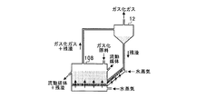
- FIG. 2 is a diagram showing a comparative example of the present embodiment.
- the separated residue of the gasification raw material having a small particle diameter is directly returned to the fluidized bed of the gasification furnace 108. Therefore, although the residue of the gasification raw material once becomes a target of the gasification reaction in the fluidized bed, the solid particles that have not been gasified are scattered in the gasification furnace 108 and are also gasified as a residue of the gasification raw material. The flow of returning to the conversion gas separator 12 is repeated.
- the residue of the gasification raw material with such a small particle size increases with the input of the gasification raw material. Then, any of the particles becomes a particle having a small particle size that cannot be collected by the gasification gas separator 12, and reaches the gas purification device in the subsequent stage together with the gasification gas, which may cause a problem of the gas purification device or the like.
- the residue of the gasification raw material collected by the conventional gasification gas separator 12 is returned to the gasification furnace 108, the residue is fluidized in the gasification furnace 108 in order to cause the gasification raw material to undergo a gasification reaction. Derived in (fluid medium).
- an inert gas such as water vapor is separately used to lead the residue of the gasification raw material to the fluidized bed of the gasification furnace 108. To form a fluidized bed.
- the gasification gas separator 112 separates the gasification gas and the residue of the gasification raw material, and then does not return the gasification raw material residue to the gasification furnace 108. Since the gas is derived directly to 102, the residue of the gasification raw material once derived is sufficiently burned through the combustion furnace 102. Therefore, the residue of the gasification raw material separated by the gasification gas separator 112 hardly returns to the gasification gas separator 112. In addition, when the residue of the gasification raw material is led out to the combustion furnace 102, there is no need to increase the lead-out speed, so there is no worry of backflow even if a fluidized bed is formed.
- the residue of the gasification raw material is not returned to the gasification furnace 108, the residue of the gasification raw material that should originally be the target of the gasification reaction in the gasification furnace 108 is extracted from the gasification furnace 108.
- the utilization efficiency of the gasification raw material in the gasification furnace 108 is lowered.
- the gasification raw material is used as a heat source for heating the fluidized medium in the combustion furnace 102 and indirectly as an energy source for the gasification reaction, it has not been scattered and used so far.
- the residue can be used as a heat source in the combustion furnace 102. Therefore, overall utilization efficiency can be increased.
- FIG. 3A and 3B are diagrams for explaining the residue deriving unit 114.
- FIG. 3A When the gasification raw material residue is derived from the gasification gas separator 112 to the combustion furnace 102, if the gasification raw material residue is derived through simple piping, the pressure in the combustion furnace 102 is higher than that of the gasification gas separator 112. There is a possibility that the fluid medium in the combustion furnace 102 flows back to the gasification gas separator 112 together. In addition, it is dangerous to ventilate the combustible gasified gas in the gasified gas separator 112 and the air in the combustion furnace 102 as they are. Therefore, in the present embodiment, as shown in FIG. 3A, a residue deriving unit 114 that seals the gasified gas separator 112 and the combustion furnace 102 is provided in a pipe between the gasified gas separator 112 and the combustion furnace 102. Provided.
- the residue deriving unit 114 is configured by a loop seal of a J-valve type tube in which the tube is formed in a J-shape, like the first seal unit 106 and the second seal unit 110, for example.
- the loop seal seals gases with a liquid or solid interposed.
- the vertical uppermost portion 114a of the recessed portion of the channel having the concave shape is lower than the vertical lowermost portion 114b of the other portion of the channel.
- the residue always stays in the concave flow path. Therefore, the space in the flow path can be divided by this residue, and communication between the combustion furnace 102 and the gasified gas separator 112 can be avoided. As a result, the residue can be appropriately led to the combustion furnace 102.
- the residue deriving unit 114 can use not only the loop seal but also a screw feeder as shown in FIG. 3B.
- the screw feeder rotates a helical screw and feeds the residue of the gasification raw material in the direction of the rotation axis.
- the residue filled in the screw feeder functions as a material seal.
- the residue of the gasification raw material separated from the gasification gas by the gasification gas separator 112 is temporarily accommodated in the container 116 by gravity, and the residue is led to the combustion furnace 102 as needed by a screw feeder.
- the gasified gas separator 112 and the combustion furnace 102 can be sealed, and communication between the combustion furnace 102 and the gasified gas separator 112 can be avoided. As a result, the residue can be appropriately led to the combustion furnace 102.
- the utilization efficiency is maintained by using the gasification raw material as a heat source in the combustion furnace 102 instead of extracting from the gasification furnace 108.
- the circulating fluidized bed gasification furnace 100 in which sand that is a fluidized medium flows in the horizontal direction has been described as an example of the circulating gasification furnace. You may use the circulating moving bed type gasifier which forms a moving bed by flowing down in the direction.
- the present invention relates to a circulation type gasification furnace that gasifies a gasification raw material by circulating a fluid medium.
Landscapes
- Chemical & Material Sciences (AREA)
- Engineering & Computer Science (AREA)
- Oil, Petroleum & Natural Gas (AREA)
- Combustion & Propulsion (AREA)
- Organic Chemistry (AREA)
- Dispersion Chemistry (AREA)
- Chemical Kinetics & Catalysis (AREA)
- General Chemical & Material Sciences (AREA)
- Materials Engineering (AREA)
- Fluidized-Bed Combustion And Resonant Combustion (AREA)
- Gasification And Melting Of Waste (AREA)
- Processing Of Solid Wastes (AREA)
Abstract
Priority Applications (3)
| Application Number | Priority Date | Filing Date | Title |
|---|---|---|---|
| AU2013233638A AU2013233638B2 (en) | 2012-03-13 | 2013-01-31 | Circulation type gasification furnace |
| CN201380012826.3A CN104159998A (zh) | 2012-03-13 | 2013-01-31 | 循环式气化炉 |
| US14/335,237 US9399738B2 (en) | 2012-03-13 | 2014-07-18 | Circulation type gasification furnace |
Applications Claiming Priority (2)
| Application Number | Priority Date | Filing Date | Title |
|---|---|---|---|
| JP2012-055323 | 2012-03-13 | ||
| JP2012055323A JP2013189510A (ja) | 2012-03-13 | 2012-03-13 | 循環式ガス化炉 |
Related Child Applications (1)
| Application Number | Title | Priority Date | Filing Date |
|---|---|---|---|
| US14/335,237 Continuation US9399738B2 (en) | 2012-03-13 | 2014-07-18 | Circulation type gasification furnace |
Publications (1)
| Publication Number | Publication Date |
|---|---|
| WO2013136868A1 true WO2013136868A1 (fr) | 2013-09-19 |
Family
ID=49160788
Family Applications (1)
| Application Number | Title | Priority Date | Filing Date |
|---|---|---|---|
| PCT/JP2013/052274 WO2013136868A1 (fr) | 2012-03-13 | 2013-01-31 | Four de gazéification à circulation |
Country Status (5)
| Country | Link |
|---|---|
| US (1) | US9399738B2 (fr) |
| JP (1) | JP2013189510A (fr) |
| CN (1) | CN104159998A (fr) |
| AU (1) | AU2013233638B2 (fr) |
| WO (1) | WO2013136868A1 (fr) |
Families Citing this family (4)
| Publication number | Priority date | Publication date | Assignee | Title |
|---|---|---|---|---|
| WO2017205943A1 (fr) * | 2016-06-03 | 2017-12-07 | Wildfire Energy Pty Ltd | Production d'un gaz et procédés associés |
| CA3060626A1 (fr) * | 2017-04-27 | 2018-11-01 | Sundrop Ip Holdings, Llc | Configurations de procede de premier etage dans un systeme de reacteur de bioreformage a 2 etages |
| CN110791326B (zh) * | 2019-11-21 | 2021-10-12 | 中国科学院工程热物理研究所 | 带气化辅床的循环流化床气化装置以及气化方法 |
| CN115109619A (zh) * | 2022-05-25 | 2022-09-27 | 华中科技大学 | 一种生物质气化炉、双炉气化装置及生物质气化系统 |
Citations (4)
| Publication number | Priority date | Publication date | Assignee | Title |
|---|---|---|---|---|
| JPS52117302A (en) * | 1976-03-26 | 1977-10-01 | Chevron Res | Method of gasifying solid carbonaceous substances |
| JPS5861181A (ja) * | 1981-10-08 | 1983-04-12 | Agency Of Ind Science & Technol | 廃棄物の熱的処理における有害成分処理方法及びその装置 |
| WO1999031202A1 (fr) * | 1997-12-18 | 1999-06-24 | Ebara Corporation | Systeme de gazeification de combustible |
| WO2010004760A1 (fr) * | 2008-07-11 | 2010-01-14 | 株式会社Ihi | Four de gazéification à lit fluidisé circulant |
Family Cites Families (16)
| Publication number | Priority date | Publication date | Assignee | Title |
|---|---|---|---|---|
| US3993583A (en) * | 1976-03-17 | 1976-11-23 | Cogas Development Company | Gasification of ash containing carbonaceous solids |
| US6408190B1 (en) * | 1999-09-01 | 2002-06-18 | Telefonaktiebolaget Lm Ericsson (Publ) | Semi built-in multi-band printed antenna |
| FI112952B (fi) * | 2001-12-21 | 2004-02-13 | Foster Wheeler Energia Oy | Menetelmä ja laitteisto hiilipitoisen materiaalin kaasuttamiseksi |
| KR100460217B1 (ko) * | 2002-06-27 | 2004-12-08 | 한국과학기술원 | 순환유동층 하강관을 이용한 석탄 가스화기 |
| FI20055237L (fi) * | 2005-05-18 | 2006-11-19 | Foster Wheeler Energia Oy | Menetelmä ja laitteisto hiilipitoisen materiaalin kaasuttamiseksi |
| WO2008102414A1 (fr) * | 2007-02-22 | 2008-08-28 | Ihi Corporation | Équipement de gazéification de combustible |
| AU2007347601B2 (en) * | 2007-02-22 | 2010-09-23 | Ihi Corporation | Method of gasifying gasification fuel and apparatus therefor |
| WO2008111127A1 (fr) * | 2007-03-14 | 2008-09-18 | Ihi Corporation | Appareillage pour la gazéification en lit fluidisé |
| JP5200691B2 (ja) * | 2008-06-20 | 2013-06-05 | 株式会社Ihi | 流動層ガス化方法及びその設備 |
| JP5282465B2 (ja) * | 2008-07-11 | 2013-09-04 | 株式会社Ihi | ガス化設備における流動層ガス化炉の流動媒体滞留時間制御方法及び装置 |
| JP5309745B2 (ja) * | 2008-07-15 | 2013-10-09 | 株式会社Ihi | ガス化設備における流動層ガス化炉の層高制御方法及び装置 |
| AU2008360805A1 (en) * | 2008-08-20 | 2010-02-25 | Ihi Corporation | Fuel gasification equipment |
| US20110142721A1 (en) * | 2008-08-20 | 2011-06-16 | Ihi Corporation | Fuel gasification equipment |
| WO2011052170A1 (fr) * | 2009-10-28 | 2011-05-05 | 株式会社Ihi | Procédé et dispositif destinés à contrôler la température d'un moteur à combustion dans un équipement de gazéification |
| JP2011105890A (ja) | 2009-11-20 | 2011-06-02 | National Institute Of Advanced Industrial Science & Technology | 循環流動層ガス化反応炉 |
| CN101880552B (zh) * | 2010-06-29 | 2013-03-27 | 中国科学院广州能源研究所 | 一种由生物质制备富氢合成气的气化装置及方法 |
-
2012
- 2012-03-13 JP JP2012055323A patent/JP2013189510A/ja active Pending
-
2013
- 2013-01-31 CN CN201380012826.3A patent/CN104159998A/zh active Pending
- 2013-01-31 AU AU2013233638A patent/AU2013233638B2/en active Active
- 2013-01-31 WO PCT/JP2013/052274 patent/WO2013136868A1/fr active Application Filing
-
2014
- 2014-07-18 US US14/335,237 patent/US9399738B2/en active Active
Patent Citations (4)
| Publication number | Priority date | Publication date | Assignee | Title |
|---|---|---|---|---|
| JPS52117302A (en) * | 1976-03-26 | 1977-10-01 | Chevron Res | Method of gasifying solid carbonaceous substances |
| JPS5861181A (ja) * | 1981-10-08 | 1983-04-12 | Agency Of Ind Science & Technol | 廃棄物の熱的処理における有害成分処理方法及びその装置 |
| WO1999031202A1 (fr) * | 1997-12-18 | 1999-06-24 | Ebara Corporation | Systeme de gazeification de combustible |
| WO2010004760A1 (fr) * | 2008-07-11 | 2010-01-14 | 株式会社Ihi | Four de gazéification à lit fluidisé circulant |
Also Published As
| Publication number | Publication date |
|---|---|
| AU2013233638B2 (en) | 2015-11-05 |
| CN104159998A (zh) | 2014-11-19 |
| JP2013189510A (ja) | 2013-09-26 |
| US20140328730A1 (en) | 2014-11-06 |
| AU2013233638A1 (en) | 2014-08-14 |
| US9399738B2 (en) | 2016-07-26 |
Similar Documents
| Publication | Publication Date | Title |
|---|---|---|
| KR101711181B1 (ko) | 고체 연료 분급 가스화-연소 이중층 병산 시스템과 방법 | |
| CN101235321B (zh) | 固体燃料的间接气化装置及方法 | |
| CN102530859B (zh) | 一种外热型微波等离子气化炉及合成气生产方法 | |
| CN105829507B (zh) | 生产代用天然气的设备和方法以及包括其的网络 | |
| ES2804520T3 (es) | Gasificación en dos etapas con enfriamiento rápido dual | |
| KR101923842B1 (ko) | 화학적 순환식 개념과 통합된 중질 액체 연료 코킹 | |
| JP6098129B2 (ja) | 循環流動層ガス化炉 | |
| WO2013136868A1 (fr) | Four de gazéification à circulation | |
| KR101813225B1 (ko) | 유동층 매체의 유속 저감을 위한 분산판이 구비된 이중 바이오매스 가스화 반응기 및 이를 포함하는 가스화 장치 | |
| CN104342212A (zh) | 粉煤流化床加氢热解与气化耦合方法 | |
| CN104640959A (zh) | 利用生物能的气化反应装置 | |
| CN103740411B (zh) | 一种新型褐煤气化反应器和气化系统 | |
| JP4622828B2 (ja) | ガス化装置 | |
| JP6412261B2 (ja) | バイオマスのガス化装置 | |
| CN106544057A (zh) | 一种木屑炭高温水蒸气气化制取富氢燃气的方法及装置 | |
| JP5605508B2 (ja) | 循環流動層式ガス化炉 | |
| KR101586425B1 (ko) | 이중 유동층 가스화기 | |
| CN205740917U (zh) | 一种固体废弃物三床联用热解气化和焦油裂解一体化系统 | |
| US20190284490A1 (en) | Industrial high-temperature reformer and reforming method | |
| JP5990978B2 (ja) | 流動層システムおよびバイオマス導入方法 | |
| CN104927922B (zh) | 移动床加压煤气化生产富甲烷煤气的工艺和装置 | |
| JP2012255114A (ja) | ガス化ガス生成システムおよびガス化ガス生成方法 | |
| JP6259991B2 (ja) | 循環流動層ガス化炉 | |
| JP6259990B2 (ja) | 循環流動層ガス化炉 | |
| JP2018172481A (ja) | ガス改質炉 |
Legal Events
| Date | Code | Title | Description |
|---|---|---|---|
| 121 | Ep: the epo has been informed by wipo that ep was designated in this application |
Ref document number: 13760739 Country of ref document: EP Kind code of ref document: A1 |
|
| ENP | Entry into the national phase |
Ref document number: 2013233638 Country of ref document: AU Date of ref document: 20130131 Kind code of ref document: A |
|
| NENP | Non-entry into the national phase |
Ref country code: DE |
|
| WWE | Wipo information: entry into national phase |
Ref document number: IDP00201405352 Country of ref document: ID |
|
| 122 | Ep: pct application non-entry in european phase |
Ref document number: 13760739 Country of ref document: EP Kind code of ref document: A1 |