WO2013136551A1 - 建設機械の操作レバー - Google Patents
建設機械の操作レバー Download PDFInfo
- Publication number
- WO2013136551A1 WO2013136551A1 PCT/JP2012/070200 JP2012070200W WO2013136551A1 WO 2013136551 A1 WO2013136551 A1 WO 2013136551A1 JP 2012070200 W JP2012070200 W JP 2012070200W WO 2013136551 A1 WO2013136551 A1 WO 2013136551A1
- Authority
- WO
- WIPO (PCT)
- Prior art keywords
- switch
- construction machine
- operation lever
- thumb
- horn
- Prior art date
- Legal status (The legal status is an assumption and is not a legal conclusion. Google has not performed a legal analysis and makes no representation as to the accuracy of the status listed.)
- Ceased
Links
Images



Classifications
-
- G—PHYSICS
- G05—CONTROLLING; REGULATING
- G05G—CONTROL DEVICES OR SYSTEMS INSOFAR AS CHARACTERISED BY MECHANICAL FEATURES ONLY
- G05G9/00—Manually-actuated control mechanisms provided with one single controlling member co-operating with two or more controlled members, e.g. selectively, simultaneously
- G05G9/02—Manually-actuated control mechanisms provided with one single controlling member co-operating with two or more controlled members, e.g. selectively, simultaneously the controlling member being movable in different independent ways, movement in each individual way actuating one controlled member only
- G05G9/04—Manually-actuated control mechanisms provided with one single controlling member co-operating with two or more controlled members, e.g. selectively, simultaneously the controlling member being movable in different independent ways, movement in each individual way actuating one controlled member only in which movement in two or more ways can occur simultaneously
- G05G9/047—Manually-actuated control mechanisms provided with one single controlling member co-operating with two or more controlled members, e.g. selectively, simultaneously the controlling member being movable in different independent ways, movement in each individual way actuating one controlled member only in which movement in two or more ways can occur simultaneously the controlling member being movable by hand about orthogonal axes, e.g. joysticks
- G05G9/04785—Manually-actuated control mechanisms provided with one single controlling member co-operating with two or more controlled members, e.g. selectively, simultaneously the controlling member being movable in different independent ways, movement in each individual way actuating one controlled member only in which movement in two or more ways can occur simultaneously the controlling member being movable by hand about orthogonal axes, e.g. joysticks the controlling member being the operating part of a switch arrangement
- G05G9/04788—Manually-actuated control mechanisms provided with one single controlling member co-operating with two or more controlled members, e.g. selectively, simultaneously the controlling member being movable in different independent ways, movement in each individual way actuating one controlled member only in which movement in two or more ways can occur simultaneously the controlling member being movable by hand about orthogonal axes, e.g. joysticks the controlling member being the operating part of a switch arrangement comprising additional control elements
-
- G—PHYSICS
- G05—CONTROLLING; REGULATING
- G05G—CONTROL DEVICES OR SYSTEMS INSOFAR AS CHARACTERISED BY MECHANICAL FEATURES ONLY
- G05G9/00—Manually-actuated control mechanisms provided with one single controlling member co-operating with two or more controlled members, e.g. selectively, simultaneously
- G05G9/02—Manually-actuated control mechanisms provided with one single controlling member co-operating with two or more controlled members, e.g. selectively, simultaneously the controlling member being movable in different independent ways, movement in each individual way actuating one controlled member only
- G05G9/04—Manually-actuated control mechanisms provided with one single controlling member co-operating with two or more controlled members, e.g. selectively, simultaneously the controlling member being movable in different independent ways, movement in each individual way actuating one controlled member only in which movement in two or more ways can occur simultaneously
- G05G9/047—Manually-actuated control mechanisms provided with one single controlling member co-operating with two or more controlled members, e.g. selectively, simultaneously the controlling member being movable in different independent ways, movement in each individual way actuating one controlled member only in which movement in two or more ways can occur simultaneously the controlling member being movable by hand about orthogonal axes, e.g. joysticks
- G05G2009/04774—Manually-actuated control mechanisms provided with one single controlling member co-operating with two or more controlled members, e.g. selectively, simultaneously the controlling member being movable in different independent ways, movement in each individual way actuating one controlled member only in which movement in two or more ways can occur simultaneously the controlling member being movable by hand about orthogonal axes, e.g. joysticks with additional switches or sensors on the handle
Definitions
- the present invention relates to an operation lever of a construction machine, for example, an operation lever used for operating a vehicle of a construction machine such as a large wheel loader.
- a construction machine such as a wheel loader is used for excavation work of natural ground and loading work of excavated earth and sand to a dump truck.
- a seesaw type forward / backward changeover switch As an operation lever for operating the vehicle of the wheel loader, a seesaw type forward / backward changeover switch, a push button type horn switch, and a pair of push button type shift switches for changing the speed stage are provided on an upper surface of a grip that can be gripped by an operator.
- a seesaw type forward / backward changeover switch As an operation lever for operating the vehicle of the wheel loader, a seesaw type forward / backward changeover switch, a push button type horn switch, and a pair of push button type shift switches for changing the speed stage are provided on an upper surface of a grip that can be gripped by an operator.
- a V-shape operation is performed in which the wheel loader is moved back and forth in a V shape using an operation lever.
- a horn is sounded to urge the dump truck to start. That is, in a series of operations, the horn switch is operated after the forward / reverse selector switch is operated for the V-shape operation.
- Patent Document 2 describes a forward / reverse lever in which a sub-shift switch is embedded in a vertical plane that faces the palm when gripped.
- An object of the present invention is to provide an operation lever for a construction machine that can easily operate a horn switch and prevent erroneous operation of the switch.
- An operation lever for a construction machine is an operation lever used for vehicle operation of a construction machine, and includes a grip portion that is gripped by an operator, and the thumb of the operator is placed on the upper surface of the grip portion.
- a vehicle operation switch having a first operation surface protruding upward from the upper surface, and a horn switch having a third operation surface substantially flush with the upper surface or sinking from the upper surface.
- the vehicle operation switch and the horn switch are arranged next to each other side by side in a swing range along the upper surface of the thumb of the operator.
- the term “substantially flush” includes the case where it protrudes slightly from the upper face due to manufacturing variations and the like with respect to the exact flush. At this time, it is important that the horn is not formed even if the protruding portion is inadvertently brought into contact with the protruding portion.
- “sunk more than the top surface” means that the horn switch is depressed to the extent that the operation of the horn switch is not hindered. Excluded when sinking beyond range.
- the horn switch is embedded in a hole provided in the upper surface, and a chamfered portion is formed in a peripheral portion of the hole.
- a speed stage changeover switch in which the second operation surface protrudes above the upper surface is provided at a position outside the thumb swing range of the upper surface. It is characterized by.
- the vehicle operation switch is a forward / reverse switching switch.
- the horn switch that is relatively frequently used is arranged side by side with the vehicle operation switch within the swing range of the thumb, and its operation surface does not protrude above the upper surface of the grip portion. Therefore, when operating the horn switch by moving the thumb from the vehicle operation switch, it is only necessary to swing the thumb so that it slides along the upper surface of the grip portion, and there is no need to lift the thumb. Easy to operate. In addition, since the horn switch does not protrude from the upper surface of the grip portion, the horn switch is not inadvertently operated, so that it is possible to prevent erroneous operation with other switches even if a conventional guard is not provided. .
- the switch operation is less likely to be hindered by the upper surface of the surrounding grip portion, and the operation surface of the horn switch can be Easy and reliable operation.
- the upper surface of the grip portion is provided with a speed stage changeover switch whose operating surface protrudes above the upper surface of the grip portion at a position outside the swing range of the thumb.
- the horn switch can be easily and clearly distinguished from the speed stage changeover switch, and it is possible to prevent erroneous operation of the switches.
- the horn switch and the speed stage changeover switch can have specifications having the same shape and dimensions, for example, and the common use of parts can be promoted, and the type of parts can be reduced.
- the vehicle operation switch is a forward / reverse changeover switch, and is the switch that is most frequently used. Therefore, the present invention is applied to two switches that are frequently used, and the usefulness of the present invention can be fully exhibited.
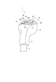
- the perspective view which shows the operation lever which concerns on one Embodiment of this invention The side view which shows the said operation lever.
- control lever 1 of this embodiment is demonstrated based on drawing.
- An operation lever 1 shown in FIG. 1 is provided in a large wheel loader as a construction machine, and is used for switching the running direction of the wheel loader and switching the speed stage. Note that the steering operation of the wheel loader can be performed by tilting the operation lever 1 to the left and right.
- the operating lever 1 is supported by a swinging portion such as a link mechanism (not shown), and is inserted through the lever member 2 attached to the swinging portion and the lever member 2, and is screwed. Etc., and a grip portion 3 fixed by, for example.
- the grip part 3 is a part to be gripped when the operator operates the operation lever 1 and is gripped by the operator's palm and fingers other than the thumb.
- the upper part of the grip part 3 is an operation part 31 extending forward as viewed from the operator seated on the control seat.
- the operation unit 31 is provided with an upper surface 310 on which various switches described later are installed.
- the upper surface 310 is formed by a first flat surface 311 on the near side as viewed from the operator and a second flat surface 312 that is continuous with the front side of the first flat surface and is inclined so as to be raised toward the front.
- a first flat surface 311 on the front side of the upper surface 310 has a seesaw-type forward / reverse selector switch 40 as a vehicle operation switch, a push-up type shift-up switch 41, a shift-down switch 42, and a horn switch. 43 is provided.
- the forward / reverse selector switch 40 is arranged so that the forward / reverse switching direction matches the front / rear direction of the wheel loader (the left / right direction in FIGS. 1 and 2).
- An operation surface (first operation surface of the present invention) 401 of the forward / reverse selector switch 40 protrudes above the upper surface 310.
- a side surface of the forward / reverse selector switch 40 that protrudes upward from the upper surface 310 is surrounded by an elastic rubber 50. The rubber 50 prevents dust and the like from entering the gap between the forward / reverse selector switch 40 and the upper surface 310.
- the forward / reverse selector switch 40 is arranged in a range where the thumb can reach when the operator holds the grip portion 3.
- a thumb is placed on the forward / reverse selector switch 40 and the front part of the forward / reverse selector switch 40 is pushed, the running direction of the wheel loader is switched to the forward side, and when the rear part is pressed, the direction is switched to the backward side. Since the forward / reverse selector switch 40 has such a function, the frequency with which the operator operates the forward / reverse selector switch 40 is the highest compared with the frequency with which the other switches 41 to 43 are operated, particularly during V-shape operation. .
- the shift-up switch 41 and the shift-down switch 42 are travel speed stage changeover switches, and are arranged in front of the forward / reverse changeover switch 40 and the horn switch 43. These shift-up switch 41 and shift-down switch 42 are pushed by slightly extending the thumb forward while holding the grip portion 3 with the operator's hand. That is, the switches 41 and 42 are arranged at positions outside the swing range of the thumb.
- the operation surfaces (second operation surface of the present invention) 411 and 421 of the shift up switch 41 and the shift down switch 42 protrude upward from the upper surface 310, and from the upper surface 310 of the shift up switch 41 and the shift down switch 42. Further, the side surfaces protruding upward are surrounded by rubbers 51 and 52, respectively. The rubbers 51 and 52 prevent dust and the like from entering the gaps between the upshift switch 41 and the downshift switch 42 and the upper surface 310.
- the traveling speed stage is sequentially increased by one stage.
- the traveling speed stage is sequentially decreased by one stage.
- the frequency with which the operator operates the upshift switch 41 and the downshift switch 42 is less than the frequency with which the forward / reverse selector switch 40 and the horn switch 43 are operated.
- the horn switch 43 is a switch that sounds a horn, and is frequently used to prompt the departure of a dump truck or the like that has been loaded when loading work such as earth and sand with the dump truck.
- a horn switch 43 is arranged adjacent to the forward / reverse selector switch 40 on the first flat surface 311. That is, the horn switch 43 is also disposed within the swing range of the thumb while the grip portion 3 is gripped by the operator's hand, like the forward / reverse selector switch 40.
- the horn switch 43 is embedded in a hole 313 provided in the operation unit 31.
- the position (the vertical position in FIG. 4) of the operation surface 431 (the third operation surface of the present invention) of the horn switch 43 is substantially flush with the first flat surface 311, and the operation surface 431 is the first flat surface 311. It is exposed in a state where it does not protrude upward.
- a peripheral portion of the hole 313 in the first flat surface 311 is a chamfered portion 314 that is chamfered.
- the chamfered portion 314 is formed of a tapered inclined surface that becomes deeper toward the center in a sectional view.
- the position of the operation surface 431 is not substantially flush with the first flat surface 311, and may be submerged than the first flat surface 311.
- Such a horn switch 43 is operated by a thumb placed in a state where the grip portion 3 is held by an operator's hand.
- the frequency at which the operator operates the horn switch 43 is roughly higher than the frequency at which the upshift switch 41 and the downshift switch 42 are operated, but less than the frequency at which the forward / reverse selector switch 40 is operated.
- an operation method of the operation lever 1 will be described by taking as an example a case of performing a loading operation of loading earth and sand on a dump truck using a wheel loader.
- the operator grips the grip portion 3, operates the forward / reverse switching switch 40 with the thumb of the gripped hand, excavates the natural ground by V-shaping the wheel loader, and dumps the excavated earth and sand.
- the wheel loader moves forward and backward, the operator extends the thumb and presses the shift-up switch 41 or the shift-down switch 42 while holding the grip portion 3 to switch the traveling speed stage of the wheel loader as necessary.
- the operator swings the thumb along the upper surface 310 so as to slide leftward from the forward / reverse selector switch 40 while holding the grip portion 3, and the horn switch 43 with the thumb. Press and sound the horn to encourage the dump truck to start.
- the present invention is not limited to the above-described embodiment, and modifications, improvements, and the like within the scope that can achieve the object of the present invention are included in the present invention.
- a construction machine other than a wheel loader such as a dump truck or a rough terrain crane may be used.
- the forward / reverse selector switch 40 has been described as the vehicle operation switch.
- a switch for raising / lowering a body provided on a dump truck may be used. It may be a change-over switch for telescopic boom telescopic operation provided on a len crane, a change-over switch for raising / lowering the outrigger device, etc., and any switch for vehicle operation may be used.
- the forward / reverse selector switch 40 is a seesaw type, but it may be a slide type or a push button type.
- the push button type it may be composed of one switch that switches between forward and backward by repeating the push operation, and separate switches for forward and reverse, and when one switch is pressed, the other switch The switch may automatically return.
- the present invention can be used as an operation lever for a construction machine used for vehicle operation of the construction machine.
Landscapes
- Physics & Mathematics (AREA)
- General Physics & Mathematics (AREA)
- Engineering & Computer Science (AREA)
- Automation & Control Theory (AREA)
- Operation Control Of Excavators (AREA)
- Mechanical Control Devices (AREA)
Description
本発明は、建設機械の操作レバーに係り、例えば大型ホイールローダなどの建設機械の車両操作に用いられる操作レバーに関する。
従来、地山の掘削作業や、掘削された土砂のダンプトラックへの積込作業には、ホイールローダなどの建設機械が用いられる。ホイールローダの車両操作を行う操作レバーとしては、オペレータによって把持可能なグリップの上面にシーソー式の前後進切換スイッチ、押ボタン式のホーンスイッチ、および速度段変更用の一対の押しボタン式のシフトスイッチを有したものが知られている(例えば、特許文献1)。
地山の掘削からダンプトラックへの積込までの一連の作業では一般的に、操作レバーを使用して、ホイールローダをV字状に前後進させるVシェープ運転が行われる。そして、土砂のダンプトラックへの積込作業が終了すると、ダンプトラックの発車を促すためにホーンが鳴らされる。すなわち、一連の作業では、Vシェープ運転のために前後進切換スイッチが操作された後、ホーンスイッチが操作される。
このように、操作レバー上の前後進切換スイッチおよびホーンスイッチを多用することから、これらのスイッチは、グリップの上面において、親指の揺動範囲内に並んで突設されている。
また、この操作レバーでは、前後進切換スイッチを操作しようとするときに、誤ってホーンスイッチを操作してしまうことを防止するために、ホーンスイッチの外周は、ホーンスイッチと同程度の高さに突設されたガードによって囲まれている。
なお、特許文献2には、把持した際の手のひらと向き合う鉛直面に副変速スイッチを埋没させた前後進レバーが記載されている。
また、この操作レバーでは、前後進切換スイッチを操作しようとするときに、誤ってホーンスイッチを操作してしまうことを防止するために、ホーンスイッチの外周は、ホーンスイッチと同程度の高さに突設されたガードによって囲まれている。
なお、特許文献2には、把持した際の手のひらと向き合う鉛直面に副変速スイッチを埋没させた前後進レバーが記載されている。
しかし、特許文献1に記載のような従来の操作レバーでは、比較的使用頻度の高いホーンスイッチを操作する度に、親指をガードの高さ以上に持ち上げて前後進切換スイッチから移動させる必要があり、長時間の作業によっては、親指が疲労してしまう可能性がある。
また、ホーンスイッチと前後進切換スイッチとが近接していることから、ホーンスイッチ側のガードが邪魔してしまい、前後進切換スイッチを押し込みにくい場合がある。
また、ホーンスイッチと前後進切換スイッチとが近接していることから、ホーンスイッチ側のガードが邪魔してしまい、前後進切換スイッチを押し込みにくい場合がある。
本発明の目的は、ホーンスイッチを容易に操作でき、かつスイッチの誤操作を防止できる建設機械の操作レバーを提供することである。
第1発明に係る建設機械の操作レバーは、建設機械の車両操作に用いられる操作レバーであって、オペレータによって把持されるグリップ部を備え、前記グリップ部の上面には、前記オペレータの親指が載置されるとともに、第1の操作面が前記上面よりも上方に突出した車両操作用スイッチと、第3の操作面が前記上面と略面一かまたは前記上面よりも沈んだホーンスイッチとが設けられ、前記車両操作用スイッチおよび前記ホーンスイッチは、前記オペレータの親指の前記上面に沿った揺動範囲内に並んで隣設されていることを特徴とする。
ここで、「略面一」には、正確な面一に対し、製造上のばらつき等に起因して、上面からわずかに突出している場合も含まれる。この際、突出部分に不用意に接触しても、不干渉域とされることで、ホーンがならないことが肝要である。
また、「前記上面よりも沈んだ」とは、ホーンスイッチの操作が阻害されない程度を限度として沈んでいることをいい、周囲の上面によって操作が阻害されるなど、親指の腹で確実に操作できる範囲を越えて沈んでいる場合は除かれる。
また、「前記上面よりも沈んだ」とは、ホーンスイッチの操作が阻害されない程度を限度として沈んでいることをいい、周囲の上面によって操作が阻害されるなど、親指の腹で確実に操作できる範囲を越えて沈んでいる場合は除かれる。
第2発明に係る建設機械の操作レバーでは、前記ホーンスイッチは、前記上面に設けられた孔部に埋設され、前記孔部の周縁部分には面取り部が形成されていることを特徴とする。
第3発明に係る建設機械の操作レバーでは、前記上面の前記親指の揺動範囲とは外れた位置には、第2の操作面が前記上面よりも上方に突出した速度段切換スイッチが設けられていることを特徴とする。
第4発明に係る建設機械の操作レバーでは、前記車両操作用スイッチは前後進切換スイッチであることを特徴とする。
第1発明によれば、比較的使用頻度が多いホーンスイッチは、親指の揺動範囲内で車両操作用スイッチと並んで配置され、その操作面がグリップ部の上面よりも上方には突出していないため、親指を車両操作用スイッチから移動させてホーンスイッチを操作するときには、グリップ部の上面に沿って親指を滑らすように揺動させるだけでよく、親指を持ち上げたりする必要がなくてホーンスイッチを容易に操作できる。また、ホーンスイッチがグリップ部の上面から突出していないことにより、ホーンスイッチを不用意に操作することがなくなるから、従来のようなガードが設けられていなくとも、他のスイッチとの誤操作を防止できる。
第2発明によれば、ホーンスイッチが埋設される孔部の周縁部分に面取り部を設けるので、周囲のグリップ部の上面によってスイッチ操作がより阻害されにくくなり、ホーンスイッチの操作面を親指の腹で容易にかつ確実に操作できる。
第3発明によれば、グリップ部の上面には、親指の揺動範囲とは外れた位置に、操作面がグリップ部の上面よりも上方に突出した速度段切換スイッチが設けられているため、ホーンスイッチが速度段切換スイッチとも容易にかつ明確に区別でき、互いのスイッチを誤って操作してしまうことをも防止できる。また、誤操作を確実に防止できることから、ホーンスイッチと速度段切換スイッチとを例えば同じ形状や寸法を有する仕様にでき、部品の共通化を促進できて部品種を低減できる。
第4発明によれば、車両操作用スイッチは前後進切換スイッチであり、使用頻度が最も多いスイッチである。このため、使用頻度の多い2つのスイッチを対象として本発明を適用することになり、本発明の有用性を十分に発揮できる。
以下、本実施形態の操作レバー1を図面に基づいて説明する。
図1に示す操作レバー1は、建設機械としての大型のホイールローダに設けられ、ホイールローダの走向方向を切り換えたり、速度段を切り換えたりするためのものである。なお、操作レバー1を左右に傾倒することにより、ホイールローダのステアリング操作が行えるようになっている。
図1に示す操作レバー1は、建設機械としての大型のホイールローダに設けられ、ホイールローダの走向方向を切り換えたり、速度段を切り換えたりするためのものである。なお、操作レバー1を左右に傾倒することにより、ホイールローダのステアリング操作が行えるようになっている。
図1~図3において、操作レバー1は、図示しないリンク機構等の揺動部に支持されており、当該揺動部に取り付けられたレバー部材2と、レバー部材2の上方に挿通され、スクリュー等で固定されたグリップ部3とを備える。
このうちのグリップ部3は、オペレータが操作レバー1を操作するときに把持する部分であり、オペレータの手のひらと親指以外の指とによって把持される。グリップ部3の上部側は、操縦シートに着座したオペレータから見てより前方に延設された操作部31になっている。
このうちのグリップ部3は、オペレータが操作レバー1を操作するときに把持する部分であり、オペレータの手のひらと親指以外の指とによって把持される。グリップ部3の上部側は、操縦シートに着座したオペレータから見てより前方に延設された操作部31になっている。
操作部31には、後述する各種スイッチが設置される上面310が設けられている。この上面310は、オペレータから見て手前側の第1平坦面311と、第1平坦面の前方側に連続し、かつ前方に向かうに従って起きがあるように傾斜した第2平坦面312とで形成されている。
上面310の手前側の第1平坦面311には、車両操作用スイッチとしてのシーソー式の前後進切換スイッチ40と、それぞれ押しボタン式とされたシフトアップスイッチ41、シフトダウンスイッチ42、およびホーンスイッチ43が設けられている。
上面310の手前側の第1平坦面311には、車両操作用スイッチとしてのシーソー式の前後進切換スイッチ40と、それぞれ押しボタン式とされたシフトアップスイッチ41、シフトダウンスイッチ42、およびホーンスイッチ43が設けられている。
前後進切換スイッチ40は、前後進の切換方向がホイールローダの前後方向(図1および図2中左右方向)に合致するように配設されている。前後進切換スイッチ40の操作面(本発明の第1の操作面)401は、上面310よりも上方に突出している。前後進切換スイッチ40の上面310よりも上方に突出した側面は、弾性を有するラバー50で囲まれている。このラバー50によって、前後進切換スイッチ40と上面310との間の隙間に塵埃などが入り込まないようになっている。
前後進切換スイッチ40は、オペレータがグリップ部3を把持した状態で親指が届く範囲に配置されている。前後進切換スイッチ40に親指を載置して前後進切換スイッチ40の前部分を押すと、ホイールローダの走向方向が前進側に切り換わり、後部分を押すと、後進側に切り換わる。前後進切換スイッチ40はこのような機能を有するため、オペレータが前後進切換スイッチ40を操作する頻度は、特にVシェープ運転の際に、他のスイッチ41~43を操作する頻度と比べて最も多い。
シフトアップスイッチ41およびシフトダウンスイッチ42は、走行速度段切換スイッチであり、前後進切換スイッチ40およびホーンスイッチ43よりも前側に配設されている。これらのシフトアップスイッチ41およびシフトダウンスイッチ42は、オペレータの手でグリップ部3を把持した状態で、親指を前側にわずかに伸ばすことで押操作される。つまり、各スイッチ41,42は、親指の揺動範囲から外れた位置に配置されている。
シフトアップスイッチ41およびシフトダウンスイッチ42の操作面(本発明の第2の操作面)411,421は、上面310よりも上方に突出しており、シフトアップスイッチ41およびシフトダウンスイッチ42の上面310よりも上方に突出した側面は、それぞれラバー51,52で囲まれている。このラバー51,52によって、シフトアップスイッチ41およびシフトダウンスイッチ42と上面310との間の隙間に塵埃などが入り込まないようになっている。
シフトアップスイッチ41を1回押すごとに、走行速度段が1段ずつ順次アップし、逆に、シフトダウンスイッチ42を1回押すごとに、走行速度段が1段ずつ順次ダウンする。オペレータがシフトアップスイッチ41およびシフトダウンスイッチ42を操作する頻度は、前後進切換スイッチ40やホーンスイッチ43を操作する頻度よりも少ない。
ホーンスイッチ43は、ホーンを鳴らすスイッチであり、ダンプトラックとともに土砂などの積込作業をしている場合では、積込を終えたダンプトラックなどに対して、発車を促すために多用される。このようなホーンスイッチ43は、第1平坦面311にて、前後進切換スイッチ40に並んで隣設されている。すなわち、ホーンスイッチ43も、前後進切換スイッチ40と同様、オペレータの手でグリップ部3を把持した状態で、親指の揺動範囲内に配設されている。
図4に示すように、ホーンスイッチ43は、操作部31に設けられた孔部313内に埋設配置されている。ホーンスイッチ43の操作面431(本発明の第3の操作面)の位置(図4における上下方向の位置)は第1平坦面311と略面一であり、操作面431は第1平坦面311よりも上方に突出していない状態で露出している。第1平坦面311のうち孔部313の周縁部分は、面取りが施された面取り部314になっている。面取り部314は、断面視において、中央に向かうに従って深くなるテーパ状の傾斜面で形成されている。ただし、操作面431の位置は、第1平坦面311と略面一ではなく、第1平坦面311よりも沈んでいてもよい。
このようなホーンスイッチ43は、オペレータの手でグリップ部3を把持した状態で載置される親指で操作される。オペレータがホーンスイッチ43を操作する頻度は、大凡ではあるが、シフトアップスイッチ41およびシフトダウンスイッチ42を操作する頻度よりも多く、前後進切換スイッチ40を操作する頻度よりも少ない。
次に、ホイールローダを用いてダンプトラックなどに土砂などを積込む積込作業を行うときを例に取って、操作レバー1の操作方法を説明する。
まず、オペレータはグリップ部3を把持し、この把持した手の親指で前後進切換スイッチ40を操作し、ホイールローダをVシェープ運転して地山を掘削するとともに、掘削された土砂などをダンプトラックに積込む。また、ホイールローダの前後進にあたっては、必要に応じてオペレータは、グリップ部3を把持したまま、親指を伸ばしてシフトアップスイッチ41又はシフトダウンスイッチ42を押し、ホイールローダの走行速度段を切り換える。
まず、オペレータはグリップ部3を把持し、この把持した手の親指で前後進切換スイッチ40を操作し、ホイールローダをVシェープ運転して地山を掘削するとともに、掘削された土砂などをダンプトラックに積込む。また、ホイールローダの前後進にあたっては、必要に応じてオペレータは、グリップ部3を把持したまま、親指を伸ばしてシフトアップスイッチ41又はシフトダウンスイッチ42を押し、ホイールローダの走行速度段を切り換える。
ダンプトラックへの積込が終了すると、オペレータはグリップ部3を把持したまま、親指を上面310に沿って前後進切換スイッチ40から左方向に滑らせるように揺動させて、親指でホーンスイッチ43を押し、ホーンを鳴らしてダンプトラックの発車を促す。
なお、本発明は前述の実施形態に限定されるものではなく、本発明の目的を達成できる範囲での変形、改良等は本発明に含まれるものである。
前記実施形態では、建設機械としてホイールローダについて説明したが、ダンプトラックやラフテレンクレーンといったホイールローダ以外の建設機械であってもよい。
前記実施形態では、建設機械としてホイールローダについて説明したが、ダンプトラックやラフテレンクレーンといったホイールローダ以外の建設機械であってもよい。
前記実施形態では、車両操作用スイッチとして前後進切換スイッチ40について説明したが、前後進切換スイッチ40ではなく、例えばダンプトラックに設けられたボディの起伏操作用の切換スイッチであってもよく、ラフテレンクレーンに設けられたテレスコピックブームの伸縮操作用の切換スイッチや、アウトリガー装置の昇降用の切換スイッチなどであってもよく、車両操作用のスイッチであればよい。
前記実施形態では、前後進切換スイッチ40はシーソー式であったが、スライド式や、押しボタン式であってもよい。そして、押しボタン式の場合では、押し操作を繰り返すことで前後進が切り換わる1つのスイッチで構成されてもよく、前進と後進とで別々のスイッチとされ、一方のスイッチが押されると他方のスイッチが自動的に戻る構成であってもよい。
本発明は、建設機械の車両操作に用いられる建設機械の操作レバーとして利用できる。
1…操作レバー、3…グリップ部、40…車両操作用スイッチである前後進切換スイッチ、41…速度段切換スイッチであるシフトアップスイッチ、42…速度段切換スイッチであるシフトダウンスイッチ、43…ホーンスイッチ、310…上面、313…孔部、314…面取り部、401,411,421,431…操作面。
Claims (4)
- 建設機械の車両操作に用いられる操作レバーであって、
オペレータによって把持されるグリップ部を備え、
前記グリップ部の上面には、前記オペレータの親指が載置されるとともに、第1の操作面が前記上面よりも上方に突出した車両操作用スイッチと、第3の操作面が前記上面と略面一かまたは前記上面よりも沈んだホーンスイッチとが設けられ、
前記車両操作用スイッチおよび前記ホーンスイッチは、前記オペレータの親指の前記上面に沿った揺動範囲内に並んで隣設されている
ことを特徴とする建設機械の操作レバー。 - 請求項1に記載の建設機械の操作レバーにおいて、
前記ホーンスイッチは、前記上面に設けられた孔部に埋設され、
前記孔部の周縁部分には面取り部が形成されている
ことを特徴とする建設機械の操作レバー。 - 請求項1または請求項2に記載の建設機械の操作レバーにおいて、
前記上面の前記親指の揺動範囲とは外れた位置には、第2の操作面が前記上面よりも上方に突出した速度段切換スイッチが設けられている
ことを特徴とする建設機械の操作レバー。 - 請求項1ないし請求項3のいずれかに記載の建設機械の操作レバーにおいて、
前記車両操作用スイッチは前後進切換スイッチである
ことを特徴とする建設機械の操作レバー。
Applications Claiming Priority (2)
| Application Number | Priority Date | Filing Date | Title |
|---|---|---|---|
| JP2012-058658 | 2012-03-15 | ||
| JP2012058658 | 2012-03-15 |
Publications (1)
| Publication Number | Publication Date |
|---|---|
| WO2013136551A1 true WO2013136551A1 (ja) | 2013-09-19 |
Family
ID=49160508
Family Applications (1)
| Application Number | Title | Priority Date | Filing Date |
|---|---|---|---|
| PCT/JP2012/070200 Ceased WO2013136551A1 (ja) | 2012-03-15 | 2012-08-08 | 建設機械の操作レバー |
Country Status (1)
| Country | Link |
|---|---|
| WO (1) | WO2013136551A1 (ja) |
Cited By (3)
| Publication number | Priority date | Publication date | Assignee | Title |
|---|---|---|---|---|
| JP2016110361A (ja) * | 2014-12-05 | 2016-06-20 | 株式会社東海理化電機製作所 | 操作検出装置 |
| JP2017033282A (ja) * | 2015-07-31 | 2017-02-09 | 株式会社クボタ | 操作装置 |
| WO2022190833A1 (ja) * | 2021-03-12 | 2022-09-15 | ヤンマーホールディングス株式会社 | 作業機械用の操作装置、及び作業機械 |
Citations (4)
| Publication number | Priority date | Publication date | Assignee | Title |
|---|---|---|---|---|
| JPH07503783A (ja) * | 1992-02-13 | 1995-04-20 | ツェットエフ、フリードリッヒスハーフェン、アクチエンゲゼルシャフト | 産業用自動車の構成要素を切換ないし操作するための操縦棒 |
| JP2000071801A (ja) * | 1998-06-19 | 2000-03-07 | Komatsu Ltd | 作業車両の操向操作レバ― |
| JP2000177436A (ja) * | 1998-12-18 | 2000-06-27 | Nissan Motor Co Ltd | 車両用運転操作装置 |
| JP2008247235A (ja) * | 2007-03-30 | 2008-10-16 | Iseki & Co Ltd | 作業車両の操作装置 |
-
2012
- 2012-08-08 WO PCT/JP2012/070200 patent/WO2013136551A1/ja not_active Ceased
Patent Citations (4)
| Publication number | Priority date | Publication date | Assignee | Title |
|---|---|---|---|---|
| JPH07503783A (ja) * | 1992-02-13 | 1995-04-20 | ツェットエフ、フリードリッヒスハーフェン、アクチエンゲゼルシャフト | 産業用自動車の構成要素を切換ないし操作するための操縦棒 |
| JP2000071801A (ja) * | 1998-06-19 | 2000-03-07 | Komatsu Ltd | 作業車両の操向操作レバ― |
| JP2000177436A (ja) * | 1998-12-18 | 2000-06-27 | Nissan Motor Co Ltd | 車両用運転操作装置 |
| JP2008247235A (ja) * | 2007-03-30 | 2008-10-16 | Iseki & Co Ltd | 作業車両の操作装置 |
Cited By (4)
| Publication number | Priority date | Publication date | Assignee | Title |
|---|---|---|---|---|
| JP2016110361A (ja) * | 2014-12-05 | 2016-06-20 | 株式会社東海理化電機製作所 | 操作検出装置 |
| JP2017033282A (ja) * | 2015-07-31 | 2017-02-09 | 株式会社クボタ | 操作装置 |
| WO2022190833A1 (ja) * | 2021-03-12 | 2022-09-15 | ヤンマーホールディングス株式会社 | 作業機械用の操作装置、及び作業機械 |
| JP2022140116A (ja) * | 2021-03-12 | 2022-09-26 | ヤンマーホールディングス株式会社 | 作業機械用の操作装置、及び作業機械 |
Similar Documents
| Publication | Publication Date | Title |
|---|---|---|
| JP6574515B1 (ja) | 操作レバー及び作業車両 | |
| US20140191559A1 (en) | Transmission and hoist control arrangement | |
| US20180067513A1 (en) | Operation device of work vehicle | |
| JP6823500B2 (ja) | 作業車両および制御方法 | |
| JP2010211695A (ja) | 作業車両の操作レバー | |
| JP4466909B2 (ja) | サヤフォーク | |
| US9395743B2 (en) | Transmission and hoist control arrangement | |
| US11787291B2 (en) | Operation device and work vehicle | |
| JP4216767B2 (ja) | 建設機械の運転操作装置 | |
| WO2023127735A1 (ja) | 操作装置および作業車両 | |
| CN112392943B (zh) | 一种按键式电子换挡器 | |
| JP2005187140A (ja) | サヤフォーク | |
| JP4466910B2 (ja) | サヤフォーク | |
| JP5378855B2 (ja) | 建設機械のシフトレバー装置 | |
| JP6008246B2 (ja) | 車両の変速操作装置 | |
| JP5945959B2 (ja) | 変速機のレンジ切替装置 | |
| KR20150073463A (ko) | 휠 굴삭기의 핸들 장치 | |
| JP4356979B2 (ja) | サヤフォーク | |
| JP2006283772A (ja) | 作業用車両における自動変速装置 | |
| JP2008273238A (ja) | シフト操作装置、及び車両の変速制御装置 | |
| JPH0526582U (ja) | ホイールローダの変速操作装置 | |
| JP6483563B2 (ja) | 操作装置 | |
| JP2002322678A (ja) | 緊急スイッチ | |
| JP2010036709A (ja) | Atシフトレバー装置 | |
| JP2008210297A (ja) | 作業車両の運転操作部 |
Legal Events
| Date | Code | Title | Description |
|---|---|---|---|
| 121 | Ep: the epo has been informed by wipo that ep was designated in this application |
Ref document number: 12871442 Country of ref document: EP Kind code of ref document: A1 |
|
| NENP | Non-entry into the national phase |
Ref country code: DE |
|
| 122 | Ep: pct application non-entry in european phase |
Ref document number: 12871442 Country of ref document: EP Kind code of ref document: A1 |