WO2013133033A1 - 輝度測定装置 - Google Patents
輝度測定装置 Download PDFInfo
- Publication number
- WO2013133033A1 WO2013133033A1 PCT/JP2013/054302 JP2013054302W WO2013133033A1 WO 2013133033 A1 WO2013133033 A1 WO 2013133033A1 JP 2013054302 W JP2013054302 W JP 2013054302W WO 2013133033 A1 WO2013133033 A1 WO 2013133033A1
- Authority
- WO
- WIPO (PCT)
- Prior art keywords
- brightness
- luminance
- measurement
- image
- unit
- Prior art date
Links
- 238000005259 measurement Methods 0.000 claims abstract description 191
- 238000005286 illumination Methods 0.000 claims description 19
- 238000009434 installation Methods 0.000 claims description 13
- 235000019557 luminance Nutrition 0.000 description 147
- 238000010586 diagram Methods 0.000 description 5
- 239000004065 semiconductor Substances 0.000 description 3
- 239000000284 extract Substances 0.000 description 1
- 238000003384 imaging method Methods 0.000 description 1
Images


Classifications
-
- G—PHYSICS
- G01—MEASURING; TESTING
- G01J—MEASUREMENT OF INTENSITY, VELOCITY, SPECTRAL CONTENT, POLARISATION, PHASE OR PULSE CHARACTERISTICS OF INFRARED, VISIBLE OR ULTRAVIOLET LIGHT; COLORIMETRY; RADIATION PYROMETRY
- G01J1/00—Photometry, e.g. photographic exposure meter
- G01J1/42—Photometry, e.g. photographic exposure meter using electric radiation detectors
- G01J1/4204—Photometry, e.g. photographic exposure meter using electric radiation detectors with determination of ambient light
-
- G—PHYSICS
- G01—MEASURING; TESTING
- G01J—MEASUREMENT OF INTENSITY, VELOCITY, SPECTRAL CONTENT, POLARISATION, PHASE OR PULSE CHARACTERISTICS OF INFRARED, VISIBLE OR ULTRAVIOLET LIGHT; COLORIMETRY; RADIATION PYROMETRY
- G01J1/00—Photometry, e.g. photographic exposure meter
- G01J1/02—Details
- G01J1/0228—Control of working procedures; Failure detection; Spectral bandwidth calculation
-
- G—PHYSICS
- G01—MEASURING; TESTING
- G01J—MEASUREMENT OF INTENSITY, VELOCITY, SPECTRAL CONTENT, POLARISATION, PHASE OR PULSE CHARACTERISTICS OF INFRARED, VISIBLE OR ULTRAVIOLET LIGHT; COLORIMETRY; RADIATION PYROMETRY
- G01J1/00—Photometry, e.g. photographic exposure meter
- G01J1/02—Details
- G01J1/0266—Field-of-view determination; Aiming or pointing of a photometer; Adjusting alignment; Encoding angular position; Size of the measurement area; Position tracking; Photodetection involving different fields of view for a single detector
-
- G—PHYSICS
- G01—MEASURING; TESTING
- G01J—MEASUREMENT OF INTENSITY, VELOCITY, SPECTRAL CONTENT, POLARISATION, PHASE OR PULSE CHARACTERISTICS OF INFRARED, VISIBLE OR ULTRAVIOLET LIGHT; COLORIMETRY; RADIATION PYROMETRY
- G01J1/00—Photometry, e.g. photographic exposure meter
- G01J1/42—Photometry, e.g. photographic exposure meter using electric radiation detectors
- G01J1/44—Electric circuits
- G01J2001/4446—Type of detector
- G01J2001/448—Array [CCD]
-
- G—PHYSICS
- G06—COMPUTING; CALCULATING OR COUNTING
- G06T—IMAGE DATA PROCESSING OR GENERATION, IN GENERAL
- G06T2207/00—Indexing scheme for image analysis or image enhancement
- G06T2207/10—Image acquisition modality
- G06T2207/10028—Range image; Depth image; 3D point clouds
-
- G—PHYSICS
- G06—COMPUTING; CALCULATING OR COUNTING
- G06T—IMAGE DATA PROCESSING OR GENERATION, IN GENERAL
- G06T2207/00—Indexing scheme for image analysis or image enhancement
- G06T2207/20—Special algorithmic details
- G06T2207/20112—Image segmentation details
Definitions
- the present invention relates to a brightness measuring device that measures the brightness of a road by image processing.
- a spot brightness meter that measures the brightness of a fixed point is used to measure the illumination surface brightness at a large number of (for example, 100) measurement points within the road illumination interval, and the brightness at each measurement point The average luminance within this interval and the uniformity of the luminance distribution were measured based on the above to confirm that these values were appropriate values.
- a spot luminance meter it is necessary to measure the luminance for each measurement point, which takes a long time.
- the surrounding environment since it takes a lot of time to measure the brightness at a number of measurement points, the surrounding environment (brightness etc.
- the image of the brightness measurement target area is photographed by an image photographing means such as a camera using a solid-state image sensor (semiconductor image sensor) such as a CCD camera, and the road is processed by image processing.
- an image photographing means such as a camera using a solid-state image sensor (semiconductor image sensor) such as a CCD camera
- the road is processed by image processing.
- a luminance measuring device that measures the luminance of the light source (see, for example, Patent Document 1).
- An object of the present invention is to solve the problems of the above-described prior art and to provide a luminance measuring device capable of measuring the luminance of a road with high accuracy by image processing.
- the present invention is a luminance measuring device for measuring the luminance of a road, and for inputting an image photographing unit for photographing an image of the road, and information concerning the road to be photographed And a luminance measurement unit for defining a luminance measurement target area based on the information input from the input unit and the information input unit, and measuring the luminance in the luminance measurement target area based on the image captured by the image capturing unit. And the luminance measurement unit divides the luminance measurement target area of the captured image into a grid having a predetermined number of grid intersections in a plan view equivalent, and assigns a luminance measurement point to each grid intersection. It features.
- the luminance measuring unit corresponds to the shape and the size of the luminance measurement target region according to the road surface to be photographed based on the information inputted from the input unit.
- a measurement range mask is generated, and the measurement range mask defines the brightness measurement target area A in an image to be processed which is captured by the image capturing unit.
- the luminance measuring unit includes an installation interval of the road illumination, a width of a lane, a number of lanes on the road, an installation height of the image capturing unit, and the image capturing unit. Forming the measurement range mask into an arbitrary shape and size based on information including an installation lane.
- the present invention is characterized in that, in the above-mentioned luminance measuring device, the luminance measuring unit outputs the luminance of each of the grid intersections in association with the coordinates of the grid intersections.
- the grid divides an image of the luminance measurement area in a predetermined number at equal intervals in a plan view equivalent to a traveling direction of a road to be photographed and a transverse direction.
- the brightness measurement unit may calculate an average brightness and a brightness uniformity of the brightness measurement target area based on the brightness of each grid intersection of the grid.
- the display unit displays an image captured by the image capturing unit, and the display unit displays the measurement range mask superimposed on the image captured by the image capturing unit. It is characterized by displaying.
- a brightness measuring device for measuring the brightness of a road, comprising: an image shooting unit for shooting an image of the road; an input unit for inputting information related to a road to be shot; And a luminance measuring unit that defines a luminance measurement target area based on information input from the input unit, and measures the luminance in the luminance measurement target area based on an image captured by the image capturing unit.
- the luminance measurement unit divides the luminance measurement target area of the captured image into a grid having a predetermined number of grid intersections in a plan view equivalent, and assigns a luminance measurement point to each grid intersection.
- image processing of (1) it is possible to measure the brightness of the road in the brightness measurement area with high accuracy.
- FIG. 1 is a block diagram showing a schematic configuration of a luminance measuring apparatus according to an embodiment of the present invention.
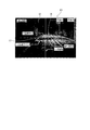
- FIG. 2 is a schematic view showing an installation state of a CCD camera at the time of luminance measurement.
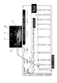
- FIG. 3 is a diagram showing an example of the measurement condition setting file.
- FIG. 4 is a diagram showing an example of display on the display unit.
- FIG. 5 is a diagram showing a luminance measurement target area and luminance measurement points in the luminance measurement target area.
- FIG. 6 is a diagram showing an example of a brightness measurement target area and an output file of the brightness measurement result.
- the brightness measuring device 1 measures the illumination surface brightness of a road illumination facility. In order to evaluate the performance of lighting facilities installed on roads, it is necessary to determine whether the average brightness of the illuminated surface (road surface or wall surface) of the lighting facility is appropriate, or whether the brightness distribution of the illuminated surface is the optimum uniformity. It is necessary to judge.
- the luminance measuring device 1 measures the average luminance of the illumination surface of the road illumination facility and the uniformity of the luminance distribution in order to evaluate the performance of the illumination facility. As shown in FIG.
- the luminance measuring device 1 includes a CCD camera 10 as an example of an image capturing unit, an input unit 11, a luminance measuring unit 12, and a display unit 13, and outputs a luminance measurement result 14. Do.
- the luminance measuring device 1 may have a configuration in which the display unit 13 is omitted.
- the CCD camera 10 inputs the formed image to the luminance measurement unit 12.
- a CCD camera using a CCD as a solid-state image sensor semiconductor image sensor
- semiconductor image sensor semiconductor image sensor
- the camera used as an image sensor may be used as an image capturing unit.
- the input unit 11 is configured such that the user can input information regarding the CCD camera 10 and the road to be photographed by the CCD camera 10. These pieces of information input by the user via the input unit 11 are output to the luminance measurement unit 12.
- the luminance measurement unit 12 includes a setting file 15 in which information input by the user is written. When new information is input through the input unit 11, the luminance measurement unit 12 edits and saves the setting file 15 based on the input information.
- the luminance measuring unit 12 measures the luminance based on information regarding the CCD camera 10 input via the input unit 11 and the road to be photographed by the CCD camera 10.
- the measurement range mask 16 that defines the luminance measurement target area A, which is the area of
- the illumination facility is designed so that the road surface brightness satisfies a predetermined condition based on the standards such as JIS and CIE.
- the road surface brightness is calculated for each installation interval (lamp interval) S of the lighting facility.
- a predetermined number of calculation points are set at predetermined positions based on a standard such as JIS or CIE within the lamp interval S, that is, within the brightness calculation area.
- the lighting facility is designed such that the average luminance of the road surface in the calculation area based on the luminance at each calculation point in the calculation area and the uniformity of the luminance distribution satisfy predetermined conditions.
- the brightness measurement target area A is set at every installation interval S of the lighting facility in order to confirm whether the road surface brightness actually meets the predetermined condition based on the standard such as JIS or CIE. Road surface brightness is measured.
- the luminance measurement target area A is the same as the calculation area at the time of lighting facility design.
- the luminance measurement device 1 measures the luminance by extracting the luminance of the same measurement point (measurement point) as the calculation point at the time of design of the illumination facility from the image I2 captured by the CCD camera 10. The road surface brightness of the target area A can be accurately determined.
- FIG. 2 is a view showing an example of the installation state of the CCD camera 10 when measuring the road surface brightness using the brightness measuring device 1.
- the CCD camera 10 is installed on the lane axis ⁇ of the brightness measurement target area A.
- the CCD camera 10 has the image center C of the CCD camera 10
- the camera is installed at a predetermined camera height H and a measurement distance D so that the position is S / 2 on the lane axis ⁇ and the depression angle is 1 degree.
- the luminance measurement target area A is set from the lamp interval S, the width W, and the number N of lanes.
- the luminance measuring device 1 is configured to be settable in accordance with the road surface to be photographed of the luminance measurement target area A photographed by the CCD camera 10, and information which is rewritten for each photographing object road surface to the setting file 15 via the input unit 11.
- the luminance measurement target area A is defined based on FIG. 3 is a view showing an example of the setting file 15. In the setting file 15, the lamp interval S, the width W, the number of lanes N, and the measurement for defining the luminance measurement target area A photographed by the CCD camera 10.
- the measurement distance D and the camera height H may be written in the setting file 15 by calculating the distance from the CCD camera 10 at which the depression angle with respect to the image center is 1 degree and the height by calculation in advance. it can.
- the measurement position P is to set which lane among the plurality of lanes in the luminance measurement target area A the CCD camera 10 is installed. For example, the measurement position P may be assigned a serial number from 1 sequentially from the left lane toward the object to be photographed, and the corresponding number may be input to the input unit 11.
- the luminance measurement device 1 generates a measurement range mask 16 corresponding to the luminance measurement target area A based on the information written in the setting file 15.
- the generated measurement range mask 16 is displayed on the display unit 13 of the luminance measurement device 1 so as to overlap the image I captured by the CCD camera 10, as shown in FIG.
- the user adjusts the CCD camera 10 so that the measurement range mask 16 displayed in the image I conforms to the road alignment, and the camera height such that the measurement range mask 16 overlaps the luminance measurement target area A exactly.
- the processing target image I2 which is an image in which the measurement range mask 16 and the luminance measurement target area A overlap each other, is captured by combining H, the measurement distance D, and the image center C.
- the measurement range mask 16 of the size and shape corresponding to the road surface to be captured is displayed on the display unit 13 when the image is captured.
- the CCD camera 10 can be adjusted to overlap properly.
- the luminance measurement target area A can be accurately set in the image I captured by the CCD camera 10 according to the conditions such as the width W of the road surface to be targeted and the number N of lanes, etc. It is possible to improve the measurement accuracy when measuring the luminance of the predetermined luminance measurement target area A.
- the luminance measurement device 1 is not limited to the road surface, It may be configured to be able to measure the luminance of the wall surface.
- the setting file 15 is configured to be able to select whether the measurement object is a road surface or a wall surface, and when the measurement object is a wall surface, for defining the luminance measurement target area A. For example, information such as the height of the lamp may be writable.
- the processing target image I2 captured by the CCD camera 10 is subjected to image processing by the luminance measuring unit 12 of the luminance measuring device 1, and the luminance of the luminance measurement target area A is measured.
- the luminance measurement unit 12 divides the luminance measurement target area A in the processing target image I2 into grids 17 having a predetermined number of grid intersections MP in a plan view equivalent.
- the grid 17 is configured by dividing the brightness measurement target area A into a predetermined number in the traveling direction of the road to be photographed and in the cross direction, and each grid intersection MP of the grid 17 is a calculation point of the brightness at the time of lighting facility design. It is comprised so that it may be arrange
- the luminance measurement unit 12 extracts road surface luminance at each grid intersection MP from the processing target image I2. That is, the luminance measurement unit 12 assigns measurement points for calculating the average luminance of the luminance measurement target area A to each grid intersection MP. Assuming that the average luminance of the luminance measurement target area A is the arithmetic average of the luminances of the respective pixels of the luminance measurement target area A, the number of pixels in the front and back sides in the luminance measurement target area A in the processing target image I2 This is because, since the apparent area is different, the consistency with the average luminance obtained from the predetermined calculation point based on the standard such as JIS or CIE can not be obtained.
- the luminance measuring unit 12 detects the position of each measurement point MP of the measurement range mask 16 disposed in the luminance measurement target area A of the photographed image I2. The luminance value of each measurement point is calculated (measured) based on the gray value of the cell. According to this configuration, the luminance measurement unit 12 arranges the grid intersection point MP at the same position as a predetermined calculation point based on a standard such as JIS or CIE in the luminance measurement target area A in the processing target image I2. Do.
- the luminance measurement unit 12 can measure the luminance of the same point as a predetermined calculation point based on the standard such as JIS or CIE in the processing object image I2 of the road surface luminance of the luminance measurement object area A.
- the average road surface brightness can be determined accurately.
- the road surface luminance at each grid intersection MP extracted from the processing target image I2 by the luminance measurement unit 12 is output in association with the coordinates of the grid intersection MP, as shown in FIG. More specifically, the luminance measuring unit 12 represents the coordinates of the grid intersection MP and the luminance at each grid intersection MP in a spreadsheet.
- the luminance measurement unit 12 determines from the spreadsheet the maximum value of the luminance in the luminance measurement target area A, the minimum value of the luminance, the average value of the luminance, the overall uniformity Uo, the maximum value of the luminance on the lane axis ⁇ , the lane
- the minimum value of the brightness on the axis ⁇ , the lane axis ⁇ uniformity (lane axis uniformity) Ul, and the like are calculated, and an output file in which these results are summarized is output as the brightness measurement result 14.
- the luminance measurement result 14 the road surface luminance at each grid intersection MP of the luminance measurement target area A, the maximum value of the luminance, the minimum value of the luminance, the average value of the luminance, the overall uniformity Uo, and the luminance on the lane axis ⁇
- the maximum value, the minimum value of the brightness on the lane axis ⁇ , the lane axis ⁇ uniformity Ul, and the like are collectively displayed in the output file.
- the user determines from the luminance measurement result 14 whether the road surface luminance actually satisfies the predetermined condition based on the standard such as JIS or CIE, and whether the lighting facility corresponds to the design value. It can be easily determined.
- the luminance measurement part 12 is this
- the luminance measurement unit 12 may be configured to obtain luminance values at predetermined points corresponding to other standards such as CIE 140, and to be able to output the luminance measurement result 14 according to the standards. good.
- the luminance measuring device 1 for measuring the illumination surface luminance of the road illumination is an input for inputting the information related to the CCD camera 10 and the road to be photographed.
- a brightness measurement unit that defines a brightness measurement target area A based on information input from the unit 11 and the input unit 11 and measures the brightness in the brightness measurement target area A based on the image I2 captured by the CCD camera 10
- the luminance measurement unit 12 divides the luminance measurement target area A of the captured image I2 into a grid 17 having a predetermined number of grid intersections MP in a plan view equivalent, and measures the luminance at each grid intersection MP Assign points.
- the image I2 to be processed by the luminance measuring apparatus 1 that measures the luminance of the luminance measurement target area A by image processing is not an apparent area in the image but an actual area equivalent to the plan view.
- the brightness can be calculated on the basis of this.
- the road surface brightness in the brightness measurement target area A can be measured with high accuracy by image processing using the CCD camera 10.
- the brightness measuring unit 12 corresponds to the shape and the size of the brightness measurement target area A according to the road surface to be photographed based on the information input from the input unit 11
- the measurement range mask 16 is generated, and the measurement range mask 16 defines the luminance measurement target area A in the image I2 to be processed which is captured by the CCD camera 10.
- the image I2 captured by the CCD camera 10 it is possible to define the luminance measurement target area A having a shape and size according to the road surface to be captured by the measurement range mask 16.
- the brightness measurement target area A in the image I2 can be changed to any shape and size according to the target road surface, and the brightness measurement device 1 can perform the brightness measurement by the image processing with high accuracy. .
- the brightness measuring unit 12 includes the lamp interval S of the road illumination, the width W of the lane, the number N of lanes on the road, the installation height H of the CCD camera 10, the CCD camera 10
- the measurement range mask 16 is formed in an arbitrary shape and size based on the information including the installation lane (measurement position) P of.
- the measurement range mask 16 optimized for each of the brightness measurement target areas A can be formed based on the road surface condition of the shooting target and the installation condition of the CCD camera 10 that can be used for shooting. Can perform luminance measurement by image processing with high accuracy.
- the luminance measuring unit 12 outputs the luminance of each grid intersection point MP in association with the coordinates of the grid intersection point MP. It can be easily determined whether there is a point that is too low or too low, and whether the brightness in the brightness measurement target area A corresponds to the design value of the illumination facility.
- the grid 17 divides the image of the brightness measurement target area A in the traveling direction of the road to be photographed and in the transverse direction into a predetermined number at equal intervals equivalent to the plan view.
- the brightness measurement unit 12 calculates the average brightness and the brightness uniformity of the brightness measurement target area A based on the brightness of each grid intersection MP of the grid 17.
- the luminance measurement target area A in the image I2 is a see-through figure of the road surface, and the apparent area is different between the front and the rear of the image I2. According to this configuration, it is the same as the calculation point at the time of design of the lighting facility.
- a grid intersection point MP which is a measurement point of brightness at a position, can be assigned to the image of the brightness measurement target area A.
- the road surface brightness can be measured not according to the apparent area in the processing target image I2 but according to the area of the actual brightness measurement target area A. Therefore, the average brightness of the brightness measurement target area A and the brightness can be accurately determined. Uniformity can be calculated.
- the display unit 13 for displaying an image captured by the CCD camera 10 is provided, and the display range 13 overlaps the image captured by the CCD camera 10 with the measurement range mask 16.
- the user adjusts the CCD camera 10 so that the measurement range mask 16 displayed in the image I displayed on the display unit 13 matches the road alignment of the measurement target, and the measurement range mask 16 measures the brightness A processing target image I2 that is an image in which the measurement range mask 16 and the luminance measurement target area A overlap with each other by matching the camera height H, the measurement distance D, and the image center C so that the target area A overlaps properly.
- the brightness measurement target area A can be accurately set in the image I captured by the CCD camera 10 according to the road surface condition to be a target, and the brightness of the brightness measurement target area A is measured using image processing. Accuracy in measurement can be improved.
Landscapes
- Physics & Mathematics (AREA)
- Spectroscopy & Molecular Physics (AREA)
- General Physics & Mathematics (AREA)
- Life Sciences & Earth Sciences (AREA)
- Sustainable Development (AREA)
- Photometry And Measurement Of Optical Pulse Characteristics (AREA)
- Traffic Control Systems (AREA)
- Studio Devices (AREA)
- Image Analysis (AREA)
- Length Measuring Devices By Optical Means (AREA)
- Image Processing (AREA)
Abstract
Description
本発明は、上述した従来の技術が有する課題を解消し、画像処理により高精度に道路の輝度を測定することができる輝度測定装置を提供することを目的とする。
本構成に係る輝度測定装置1は、道路照明施設の照射面輝度を測定するものである。道路に設置される照明施設は、その性能を評価するために、照明施設の照射面(路面あるいは壁面)の平均輝度が適切であるか、照射面の輝度分布が最適な均斉度であるかを判定する必要がある。輝度測定装置1は、照明施設の性能を評価すべく、道路照明施設の照射面の平均輝度、及び、輝度分布の均斉度を測定するものである。
輝度測定装置1は、図1に示すように、画像撮影部の一例としてのCCDカメラ10と、入力部11と、輝度測定部12と、表示部13と、を備え、輝度測定結果14を出力する。なお、輝度測定装置1は、表示部13を省略した構成であっても良い。
ところで、道路に照明施設を設置する際には、JISやCIE等の規格に基づいて、路面輝度が所定の条件を満たすように照明施設を設計する。一般的には、照明施設の設計時には、照明施設の設置間隔(灯具間隔)S毎に路面輝度が計算される。灯具間隔S内、つまり、輝度の計算領域内には、JISやCIE等の規格に基づいて所定数の計算ポイントが所定の位置に設定される。そして、照明施設は、計算領域内の各計算ポイントでの輝度に基づく当該計算領域内の路面の平均輝度、及び、輝度分布の均斉度が所定の条件を満たすように設計される。
図3は、設定ファイル15の一例を示す図であり、設定ファイル15には、CCDカメラ10で撮影する輝度測定対象領域Aを規定するための、灯具間隔S、幅員W、車線数N、測定距離D、カメラ高さ(測定高さ)H、測定位置P、レンズ焦点距離等の情報が書き換え可能に書き込まれている。なお、測定距離D、及び、カメラ高さHは、CCDカメラ10から画像中心に対しての俯角が1度となる距離、及び、高さを予め計算により求めて、設定ファイル15に書き込むことができる。また、測定位置Pは、輝度測定対象領域A内の複数ある車線のうち、どの車線にCCDカメラ10が設置されているかを設定するものである。測定位置Pは、例えば、撮影対象に向かって左側の車線から順に1から連番の番号を割り当てて、対応する番号を入力部11に入力する構成であっても良い。
この構成によれば、輝度測定部12は、処理対象画像I2中の輝度測定対象領域Aに平面図相当でJISやCIE等の規格に基づいた所定の計算ポイントと同じ位置に格子交点MPを配置する。これにより、輝度測定部12は、輝度測定対象領域Aの路面輝度を処理対象画像I2中のJISやCIE等の規格に基づいた所定の計算ポイントと同じ点の輝度を測定することができるため、正確に平均路面輝度を求めることができる。
この構成によれば、画像処理により輝度測定対象領域Aの輝度を測定する輝度測定装置1の処理対象となる画像I2から、画像内の見かけ上の面積ではなく、平面図相当の実際の面積に基づいて輝度を計算することができる。これにより、CCDカメラ10を用いて画像処理により高精度に輝度測定対象領域A内の路面輝度を測定することができる。
I2 処理対象画像(画像)
10 CCDカメラ(画像撮影部)
11 入力部
12 輝度測定部
13 表示部
16 測定範囲マスク
17 グリッド
A 輝度測定対象領域
MP 格子交点(測定点)
Claims (6)
- 道路の輝度を測定する輝度測定装置であって、
前記道路の画像を撮影するための画像撮影部と、
撮影対象の道路に係る情報を入力するための入力部と、
前記入力部から入力された情報に基づいて輝度測定対象領域を規定し、前記輝度測定対象領域内の輝度を前記画像撮影部で撮影された画像に基づいて測定する輝度測定部と、を備え、
前記輝度測定部は、撮影された画像の前記輝度測定対象領域を平面図相当で、所定数の格子交点を有するグリッドに切り分け、各格子交点に輝度の測定点を割り当てる
ことを特徴とする輝度測定装置。 - 前記輝度測定部は、前記入力部から入力される情報に基づいて撮影対象の路面に応じた前記輝度測定対象領域の形及び大きさに対応する測定範囲マスクを生成し、前記測定範囲マスクは、前記画像撮影部で撮影された処理対象となる画像中に前記輝度測定対象領域Aを規定することを特徴とする請求項1に記載の輝度測定装置。
- 前記輝度測定部は、前記道路照明の設置間隔、車線の幅員、道路上の車線数、前記画像撮影部の設置高さ、前記画像撮影部の設置車線、を含む情報に基づいて前記測定範囲マスクを任意の形及び大きさに形成することを特徴とする請求項1又は2に記載の輝度測定装置。
- 前記輝度測定部は、前記各格子交点の輝度を当該格子交点の座標に対応づけて出力することを特徴とする請求項1乃至3のいずれかに記載の輝度測定装置。
- 前記グリッドは、撮影対象の道路の進行方向、及び、横断方向に前記輝度測定対象領域の画像を平面図相当で等間隔に所定数に分割して構成され、
前記輝度測定部は、前記グリッドの各格子交点の輝度に基づいて、前記輝度測定対象領域の平均輝度、及び、輝度均斉度を算出することを特徴とする請求項4に記載の輝度測定装置。 - 前記画像撮影部で撮影する画像を表示する表示部を備え、当該表示部に、前記測定範囲マスクを、前記画像撮影部で撮影する画像に重ねて表示することを特徴とする請求項2乃至6のいずれか一項に記載の輝度測定装置。
Priority Applications (2)
| Application Number | Priority Date | Filing Date | Title |
|---|---|---|---|
| US14/382,646 US20150022659A1 (en) | 2012-03-06 | 2013-02-21 | Luminance measuring apparatus |
| CN201380012918.1A CN104185777B (zh) | 2012-03-06 | 2013-02-21 | 亮度测量装置 |
Applications Claiming Priority (2)
| Application Number | Priority Date | Filing Date | Title |
|---|---|---|---|
| JP2012-049088 | 2012-03-06 | ||
| JP2012049088A JP5742753B2 (ja) | 2012-03-06 | 2012-03-06 | 輝度測定装置 |
Publications (1)
| Publication Number | Publication Date |
|---|---|
| WO2013133033A1 true WO2013133033A1 (ja) | 2013-09-12 |
Family
ID=49116516
Family Applications (1)
| Application Number | Title | Priority Date | Filing Date |
|---|---|---|---|
| PCT/JP2013/054302 WO2013133033A1 (ja) | 2012-03-06 | 2013-02-21 | 輝度測定装置 |
Country Status (4)
| Country | Link |
|---|---|
| US (1) | US20150022659A1 (ja) |
| JP (1) | JP5742753B2 (ja) |
| CN (1) | CN104185777B (ja) |
| WO (1) | WO2013133033A1 (ja) |
Cited By (1)
| Publication number | Priority date | Publication date | Assignee | Title |
|---|---|---|---|---|
| EP3839482A1 (en) | 2019-12-19 | 2021-06-23 | Tallinn University of Technology | Method and device for measuring charcteristics of refelection of light on surfaces |
Families Citing this family (11)
| Publication number | Priority date | Publication date | Assignee | Title |
|---|---|---|---|---|
| CN105157828B (zh) * | 2015-08-17 | 2017-10-10 | 上海熙视光电科技有限公司 | 一种汽车内饰件led灯带辉度值检测系统 |
| KR101859627B1 (ko) | 2016-08-05 | 2018-05-18 | 주식회사 로드텍 | 차선 재귀 반사 휘도 측정 시스템 및 방법 |
| CN106679804B (zh) * | 2016-12-09 | 2022-03-29 | 上海航空电器有限公司 | 一种便携式模块化亮度色度的检测方法 |
| WO2018153791A1 (en) * | 2017-02-22 | 2018-08-30 | Philips Lighting Holding B.V. | Street light uniformity measurement using data collected by a camera-equipped vehicle |
| CN108010071B (zh) * | 2017-12-01 | 2022-03-25 | 中国人民解放军后勤工程学院 | 一种利用3d深度测量的亮度分布测量系统及方法 |
| CN108259775B (zh) * | 2018-04-09 | 2021-01-22 | 京东方科技集团股份有限公司 | 一种成像方法、成像装置及后视镜 |
| US10380440B1 (en) | 2018-10-23 | 2019-08-13 | Capital One Services, Llc | Method for determining correct scanning distance using augmented reality and machine learning models |
| JP7147690B2 (ja) | 2019-06-04 | 2022-10-05 | 横浜ゴム株式会社 | シーラント材組成物 |
| JP7446830B2 (ja) | 2020-01-30 | 2024-03-11 | フォルシアクラリオン・エレクトロニクス株式会社 | 画像処理装置及び画像処理方法 |
| JP7389358B2 (ja) | 2020-06-19 | 2023-11-30 | 横浜ゴム株式会社 | シーラント材組成物 |
| CN113091889A (zh) * | 2021-02-20 | 2021-07-09 | 周春伟 | 一种测量道路亮度的方法及装置 |
Citations (4)
| Publication number | Priority date | Publication date | Assignee | Title |
|---|---|---|---|---|
| JPH0240514A (ja) * | 1988-08-01 | 1990-02-09 | Matsushita Electric Ind Co Ltd | 路面輝度計 |
| JPH08237642A (ja) * | 1995-02-22 | 1996-09-13 | Toyota Motor Corp | 移動体検出装置及び移動体検出方法 |
| JP2002140696A (ja) * | 2000-11-06 | 2002-05-17 | Toyota Central Res & Dev Lab Inc | 撮像及び画像変換装置 |
| JP2008276642A (ja) * | 2007-05-02 | 2008-11-13 | Xanavi Informatics Corp | 走行車線認識装置および走行車線認識方法 |
Family Cites Families (5)
| Publication number | Priority date | Publication date | Assignee | Title |
|---|---|---|---|---|
| JPH0217420A (ja) * | 1988-07-05 | 1990-01-22 | Matsushita Electric Ind Co Ltd | 路面輝度測定装置 |
| US6674434B1 (en) * | 1999-10-25 | 2004-01-06 | Navigation Technologies Corp. | Method and system for automatic generation of shape and curvature data for a geographic database |
| DE102008002026A1 (de) * | 2008-05-28 | 2009-12-03 | Robert Bosch Gmbh | Vorrichtung, Kamera und Verfahren zur Erzeugung von Bildern der Umgebung eines Kraftfahrzeuges |
| CN102103015B (zh) * | 2009-12-21 | 2012-08-29 | 厦门市光电子行业协会 | 一种led道路照明现场动态测量方法 |
| CN101858781B (zh) * | 2010-06-09 | 2011-12-14 | 天津大学 | 基于遥控车载平台的居住区夜间光环境检测系统 |
-
2012
- 2012-03-06 JP JP2012049088A patent/JP5742753B2/ja active Active
-
2013
- 2013-02-21 US US14/382,646 patent/US20150022659A1/en not_active Abandoned
- 2013-02-21 WO PCT/JP2013/054302 patent/WO2013133033A1/ja active Application Filing
- 2013-02-21 CN CN201380012918.1A patent/CN104185777B/zh active Active
Patent Citations (4)
| Publication number | Priority date | Publication date | Assignee | Title |
|---|---|---|---|---|
| JPH0240514A (ja) * | 1988-08-01 | 1990-02-09 | Matsushita Electric Ind Co Ltd | 路面輝度計 |
| JPH08237642A (ja) * | 1995-02-22 | 1996-09-13 | Toyota Motor Corp | 移動体検出装置及び移動体検出方法 |
| JP2002140696A (ja) * | 2000-11-06 | 2002-05-17 | Toyota Central Res & Dev Lab Inc | 撮像及び画像変換装置 |
| JP2008276642A (ja) * | 2007-05-02 | 2008-11-13 | Xanavi Informatics Corp | 走行車線認識装置および走行車線認識方法 |
Non-Patent Citations (1)
| Title |
|---|
| HIROYUKI KOBAYASHI ET AL.: "A Study on The Front Vehicles Pursuit Using A Taillight and Texture Information", IEICE TECHNICAL REPORT, vol. 104, no. 420, 8 November 2004 (2004-11-08), pages 7 - 10 * |
Cited By (1)
| Publication number | Priority date | Publication date | Assignee | Title |
|---|---|---|---|---|
| EP3839482A1 (en) | 2019-12-19 | 2021-06-23 | Tallinn University of Technology | Method and device for measuring charcteristics of refelection of light on surfaces |
Also Published As
| Publication number | Publication date |
|---|---|
| JP5742753B2 (ja) | 2015-07-01 |
| CN104185777A (zh) | 2014-12-03 |
| CN104185777B (zh) | 2016-04-27 |
| US20150022659A1 (en) | 2015-01-22 |
| JP2013185857A (ja) | 2013-09-19 |
Similar Documents
| Publication | Publication Date | Title |
|---|---|---|
| WO2013133033A1 (ja) | 輝度測定装置 | |
| JP2013185857A5 (ja) | ||
| CN107507558B (zh) | 一种led显示屏的校正方法 | |
| US10560686B2 (en) | Photographing device and method for obtaining depth information | |
| CN103778887A (zh) | Led显示装置的亮度校正方法及装置 | |
| JP6937642B2 (ja) | 表面評価方法及び表面評価装置 | |
| CN105051506B (zh) | 亮度测量方法、亮度测量装置和使用它们的画质调整技术 | |
| RU2013141224A (ru) | Способ и система калибровки камеры | |
| CN109862345B (zh) | 视场角测试方法和系统 | |
| JP2012047673A (ja) | 検査装置及び検査方法 | |
| JP2010025855A (ja) | 軌道変位測定装置 | |
| CN102628678B (zh) | 三维测量装置、三维测量方法 | |
| CN104658461A (zh) | 显示器发光均匀性的测试方法 | |
| KR20200081541A (ko) | 촬상 장치 및 이의 구동 방법 | |
| JP5566516B2 (ja) | 軌道変位測定装置 | |
| KR101668039B1 (ko) | 디스플레이 패널 점등 검사방법 | |
| EP3660452B1 (en) | Positioning system and positioning method | |
| CN102479005B (zh) | 二维光学检测的平场校正方法 | |
| JP2018205062A (ja) | 評価方法及び評価システム | |
| CN103528801A (zh) | Led灯具统一眩光值光学测量装置 | |
| JP2017514185A (ja) | 着用型投影装置及び投影方法 | |
| JPWO2012169131A1 (ja) | キャリブレーション装置及びキャリブレーション方法 | |
| JP2011002401A (ja) | 輝度測定装置における補正係数算出方法および輝度測定装置 | |
| CN106097297B (zh) | 一种摄像头遮挡范围计算方法 | |
| JP6159665B2 (ja) | 自動車の番号標等の照度測定装置及び測定方法 |
Legal Events
| Date | Code | Title | Description |
|---|---|---|---|
| WWE | Wipo information: entry into national phase |
Ref document number: 201380012918.1 Country of ref document: CN |
|
| 121 | Ep: the epo has been informed by wipo that ep was designated in this application |
Ref document number: 13757082 Country of ref document: EP Kind code of ref document: A1 |
|
| WWE | Wipo information: entry into national phase |
Ref document number: 14382646 Country of ref document: US |
|
| NENP | Non-entry into the national phase |
Ref country code: DE |
|
| 122 | Ep: pct application non-entry in european phase |
Ref document number: 13757082 Country of ref document: EP Kind code of ref document: A1 |