WO2013132694A1 - イオン発生装置 - Google Patents
イオン発生装置 Download PDFInfo
- Publication number
- WO2013132694A1 WO2013132694A1 PCT/JP2012/079013 JP2012079013W WO2013132694A1 WO 2013132694 A1 WO2013132694 A1 WO 2013132694A1 JP 2012079013 W JP2012079013 W JP 2012079013W WO 2013132694 A1 WO2013132694 A1 WO 2013132694A1
- Authority
- WO
- WIPO (PCT)
- Prior art keywords
- discharge electrode
- ion generator
- air
- discharge
- electrode
- Prior art date
- Legal status (The legal status is an assumption and is not a legal conclusion. Google has not performed a legal analysis and makes no representation as to the accuracy of the status listed.)
- Ceased
Links
Images









Classifications
-
- H—ELECTRICITY
- H01—ELECTRIC ELEMENTS
- H01T—SPARK GAPS; OVERVOLTAGE ARRESTERS USING SPARK GAPS; SPARKING PLUGS; CORONA DEVICES; GENERATING IONS TO BE INTRODUCED INTO NON-ENCLOSED GASES
- H01T23/00—Apparatus for generating ions to be introduced into non-enclosed gases, e.g. into the atmosphere
-
- G—PHYSICS
- G03—PHOTOGRAPHY; CINEMATOGRAPHY; ANALOGOUS TECHNIQUES USING WAVES OTHER THAN OPTICAL WAVES; ELECTROGRAPHY; HOLOGRAPHY
- G03G—ELECTROGRAPHY; ELECTROPHOTOGRAPHY; MAGNETOGRAPHY
- G03G15/00—Apparatus for electrographic processes using a charge pattern
- G03G15/02—Apparatus for electrographic processes using a charge pattern for laying down a uniform charge, e.g. for sensitising; Corona discharge devices
- G03G15/0291—Apparatus for electrographic processes using a charge pattern for laying down a uniform charge, e.g. for sensitising; Corona discharge devices corona discharge devices, e.g. wires, pointed electrodes, means for cleaning the corona discharge device
-
- H—ELECTRICITY
- H01—ELECTRIC ELEMENTS
- H01J—ELECTRIC DISCHARGE TUBES OR DISCHARGE LAMPS
- H01J27/00—Ion beam tubes
- H01J27/02—Ion sources; Ion guns
- H01J27/022—Details
-
- H—ELECTRICITY
- H01—ELECTRIC ELEMENTS
- H01J—ELECTRIC DISCHARGE TUBES OR DISCHARGE LAMPS
- H01J27/00—Ion beam tubes
- H01J27/02—Ion sources; Ion guns
- H01J27/26—Ion sources; Ion guns using surface ionisation, e.g. field effect ion sources, thermionic ion sources
-
- H—ELECTRICITY
- H01—ELECTRIC ELEMENTS
- H01T—SPARK GAPS; OVERVOLTAGE ARRESTERS USING SPARK GAPS; SPARKING PLUGS; CORONA DEVICES; GENERATING IONS TO BE INTRODUCED INTO NON-ENCLOSED GASES
- H01T19/00—Devices providing for corona discharge
- H01T19/04—Devices providing for corona discharge having pointed electrodes
Definitions
- the present invention relates to an ion generator for generating air ions for removing static electricity charged on a jig for assembling an electronic component, a packaging film made of a plastic material, or the like.
- an ion generator called an ionizer or ion generator is used.
- an ion generator for example, a blow type in which air ions are supplied to a predetermined static elimination part by a tube or a pipe, and air ions are blown to the static elimination part by a fan from the outlet of the ion generation apparatus.
- a fan type for example, a blow type in which air ions are supplied to a predetermined static elimination part by a tube or a pipe, and air ions are blown to the static elimination part by a fan from the outlet of the ion generation apparatus.
- the ion generator is a device that generates air ions having positive polarity or negative polarity, and neutralizes and eliminates charged static electricity by supplying the generated air ions to a charged portion.
- the ion generator includes an electrode such as a discharge needle to which a high voltage is applied, and an AC voltage or a pulsed DC voltage of several kV (for example, 7 kV) or more is applied to the electrode. By applying a high voltage, a corona discharge is generated from the electrode, and the surrounding air is ionized by the corona discharge.
- Patent Document 1 a technique described in Patent Document 1 is known.
- a bundle electrode in which a plurality of thin wires are bundled in a brush shape is used as an electrode.
- a high voltage is applied to the bundle electrode from a high-voltage power source, and the thin wires of the bundle electrode are charged by the application of the high voltage.
- the fine wires are repelled from each other due to the charging of the fine wires, and the tips of the bundle-shaped electrodes are radially enlarged, and corona discharge is generated under this state.
- air ions are generated in a wide range and the ionization efficiency is increased while the apparatus is made compact by using bundled electrodes.
- the amount of bending deformation differs greatly between the thin wire in the central portion and the thin wire in the outer peripheral portion. That is, when the tip of the bundle electrode is radially expanded during corona discharge, the fine wire at the center is almost straight and hardly bent, but the fine wire at the outer periphery is greatly bent and deformed (for example, bent at a right angle). Will do. Therefore, the thin wire in the outer peripheral portion is easy to break (wear), and it is necessary to frequently observe the state of the bundle electrode, which may lead to complicated maintenance.
- An object of the present invention is to provide an ion generator capable of simplifying maintenance while improving ionization efficiency.
- the ion generator of the present invention is an ion generator having a fixed end and a free end, and having a flexible discharge electrode, and is generated by supplying a high voltage to the fixed end.
- the free end side swivels or swings around the fixed end by a repulsive force of discharge.
- the ion generator of the present invention is characterized in that a swivel motion control member for controlling the swivel motion state of the discharge electrode is provided.
- the ion generator of the present invention is characterized in that the discharge electrode is disposed in an air supply path that guides air toward an air outlet, and the free end swings.
- the ion generator of the present invention is characterized in that the free end of the discharge electrode swings in a direction crossing the air flow toward the air outlet.
- the ion generator of the present invention is characterized in that the discharge electrode is arranged in a direction toward the air outlet.
- the ion generator of the present invention is characterized in that a cross-sectional dimension of the discharge electrode is set to 100 ⁇ m or less.
- the ion generator of the present invention is characterized in that the discharge electrode is formed of a titanium alloy.
- the ion generator of the present invention includes a discharge electrode having flexibility, and the free end of the discharge electrode is centered on the fixed end due to the repulsive force of corona discharge generated by supplying a high voltage to the fixed end of the discharge electrode. Therefore, the amount of dust generated from the free end side of the discharge electrode can be greatly reduced as compared with a bundle electrode composed of a plurality of thin wires. Therefore, the maintenance cycle of the apparatus can be extended. If the number of discharge electrodes is one, the apparatus can be made compact, the state of the discharge electrodes can be easily observed, and the maintenance can be simplified. Since the discharge electrode swings or swings, the generated air ions can be transported over a wide range of the static elimination object, and ionization efficiency can be increased.
- the size of the transport range of the generated air ions can be arbitrarily controlled according to the shape of the object to be neutralized. can do.
- the ionized air ions when the discharge electrode is swung in a direction crossing the air flow flowing through the air supply path, the ionized air ions can be dispersed in the air flow over a wide range. Thereby, the distribution density of the air ions discharged from the air outlet is made uniform as a whole, and the entire surface of the object to be neutralized can be uniformly neutralized.
- the discharge electrode since the cross sectional dimension of the discharge electrode is set to 100 ⁇ m or less, the discharge electrode can have sufficient flexibility, and the generated air ions can be conveyed over a wider range. it can.
- the discharge electrode is formed of a titanium alloy, for example, the amount of dust generation can be reduced while ensuring high strength as compared with a tungsten alloy, and the maintenance cycle of the device is further extended. be able to.
- (A), (b) is explanatory drawing explaining the 1st adjustment state (conveyance width
- FIG. 13 is a plan view of FIG. 12. It is sectional drawing of the EE line direction in FIG. It is a top view which shows the ion generator which is 8th Embodiment.
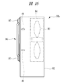
- FIG. 16 is a right side view of FIG. 15.
- FIG. 16 is a cross-sectional view in the direction of line FF in FIG. 15.
- It is sectional drawing of FIG. It is a front view which shows the ion generator which is 10th Embodiment.
- (A) is the schematic which shows the air ion production
- (b) is the schematic which shows the air ion production
- FIG. 1 is an explanatory diagram for explaining an application example of the ion generator according to the present invention
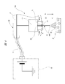
- FIG. 2 is an explanatory diagram for explaining the structure of the ion generator according to the first embodiment
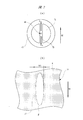
- FIG. 3 is an ion generator of FIG.
- size of the conveyance range of the air ion in an apparatus is each represented.
- FIG. 1 shows an example in which an ion generator 30a is applied to a film supply device 20 that supplies a packaging film (work) 10, and the ion generator 30a charges a packaging film 10 as a charge removal object. Used to remove static electricity.
- the ion generator 30 a includes an apparatus main body 40 that generates air ions EI, a power supply unit 50 that supplies a high voltage of about 5 kV to the apparatus main body 40, and one end side to the power supply unit 50.
- a power cable 51 that is electrically connected and whose other end is electrically connected to the apparatus main body 40 is provided.
- the power supply unit 50 shown in FIG. 2 is described so as to supply a positive high voltage. However, in some cases, a negative high voltage may be supplied. Further, a positive high voltage power supply unit and a negative high voltage may be supplied.
- a voltage power supply unit may be prepared, and the respective high voltages may be supplied to the two apparatus main bodies 40.
- the apparatus main body 40 is a so-called bar-type ionizer, and is attached to a predetermined portion of a support frame (not shown) forming the film supply apparatus 20 and is disposed to face the moving packaging film 10.
- the apparatus main body 40 generates a corona discharge by applying a high voltage from the power supply unit 50, and the surrounding air is ionized by the corona discharge to generate positive or negative air ions EI.
- the generated air ions EI are sprayed toward the packaging film 10.
- the packaging film 10 is formed into a thin sheet shape with a plastic material, and the tip end side thereof is sent out in the direction of arrow M by the rotational drive of the pair of roller members 21 and 22 in the direction of the arrow in the figure.
- the packaging film 10 is charged with static electricity when the roller members 21 and 22 come into contact with each other and are then separated from each other.
- the packaging film 10 passes through the portion of the apparatus main body 40 immediately after passing through the roller members 21 and 22. It has become.
- the apparatus main body 40 includes a plurality of discharge nozzles 41, and the discharge nozzles 41 are provided at equal intervals along the longitudinal direction of the apparatus main body 40. From each discharge nozzle 41, air ions EI are blown out toward the packaging film 10, respectively. The air ions EI blown out from the discharge nozzles 41 reach the packaging film 10 respectively, and neutralize and remove the charged portions E (shaded portions in the figure) where static electricity is charged on the packaging film 10. It has become. In this way, static electricity can be removed from the packaging film 10 that has passed through the portion of the apparatus main body 40.
- symbol F indicates a static elimination site from which static electricity has been removed.
- the apparatus main body 40 is arranged so that its longitudinal direction is parallel to the width direction of the packaging film 10 (direction perpendicular to the arrow M direction).
- the apparatus main body 40 may be arranged so that the longitudinal direction thereof is parallel to the delivery direction of the packaging film 10 (arrow M direction).
- the air ions EI can be conveyed to the charged portion E of the packaging film 10 for a long time, it is possible to eliminate the charge more effectively by extending the charge removal time accordingly.
- the packaging film 10 is charged with negative (negative polarity) static electricity, and positive (positive polarity) air ions EI that neutralize the discharge nozzle 41 are blown out.
- the apparatus main body 40 forming the ion generator 30a includes a casing 42 formed in a substantially rectangular parallelepiped shape. Inside the casing 42, a plurality of bases 43 are provided at substantially equal intervals along the longitudinal direction thereof. Each base 43 is formed in a substantially cylindrical shape by a resin material such as plastic, and a terminal (not shown) on the other end side where the power cable 51 is branched is inserted from the upper end portion of each base 43 in the figure. It is.
- a fixed end (base end) 44a of each discharge electrode 44 forming each discharge nozzle 41 is inserted at the lower end portion of each base 43 in the drawing and at the center of each base 43.
- Each discharge electrode 44 is provided in correspondence with each of the bases 43, so that the fixed end 44 a of each discharge electrode 44 is connected to each of the other ends of the power cable 51 inside each base 43.
- Each terminal is electrically connected.
- Each discharge electrode 44 is electrically connected to each terminal on the other end side of the power cable 51 inside each base 43 by mounting each discharge nozzle 41 on the casing 42.
- Each discharge electrode 44 is formed in a thread shape having a circular cross section made of a titanium alloy material, and its diameter dimension, that is, the cross-sectional dimension is set to 100 ⁇ m (0.1 mm) or less, for example, 70 ⁇ m (0.07 mm). Yes. Thereby, each discharge electrode 44 made of a relatively hard titanium alloy is flexible and elastically deformable, and the distal end side of each discharge electrode 44 becomes a free end 44b that can freely move in the front-rear and left-right directions. .
- each discharge electrode 44 has a fixed end so as to form a substantially conical shape within a predetermined angle range, as shown by a two-dot chain line arrow in the figure, due to the repulsive force of corona discharge generated when a high voltage is applied. Rotate around 44a.
- the magnitude of the turning motion on the free end 44b side is determined by the rigidity of each discharge electrode 44 and the magnitude of the voltage applied to each discharge electrode 44.
- each discharge electrode 44 can be easily elastically deformed, and consequently the magnitude of the turning motion can be increased.
- the repulsive force of the corona discharge can be increased by increasing the voltage applied to each discharge electrode 44, and consequently the magnitude of the turning motion can be increased.
- the minimum diameter dimension of the discharge electrode 44 and the magnitude of the voltage applied to the discharge electrode 44 are determined in consideration of the rigidity of the material (titanium, tungsten, stainless steel, etc.) forming the discharge electrode 44.
- a titanium alloy having sufficient flexibility and rigidity and capable of suppressing the amount of dust generation is used as the optimum material.
- each discharge electrode 44 is provided on each base 43 and there is nothing that obstructs the swivel movement by contacting each discharge electrode 44, each discharge electrode 44 is provided in the front-rear and left-right directions. In the same angle range, they are elastically deformed and turn. Thereby, as shown in FIG. 3, the air ion EI can be made to reach the conveyance range a1 of the diameter dimension d1 in the packaging film 10 in a circular shape.
- Corona discharge is generated in an irregular direction (front-rear and left-right directions) from the free end 44b side of each discharge electrode 44, and a repulsive force is generated in a direction opposite to the direction in which the corona discharge is generated.
- the repulsive force due to the corona discharge causes the free end 44b side of each discharge electrode 44 to bend in a direction opposite to the direction in which the corona discharge occurs. Since the generation direction of the corona discharge changes irregularly, the free end 44b side of each discharge electrode 44 thereby swivels so as to form a substantially conical shape as shown by a two-dot chain line in the figure. Therefore, positive air ions EI are blown out from the free end 44 b side of each discharge electrode 44 over a wide range of the packaging film 10.
- each conveyance range a1 of each discharge electrode 44 is partially overlapped with each other in the width direction (left-right direction in the drawing) of the packaging film 10. Thereby, the whole area (shaded part in a figure) of the electrification site
- the rotational speed (work feed speed) of the roller members 21 and 22 of the film supply apparatus 20 is about 2 when the part passes through the transport range a1 when a part of the packaging film 10 is viewed.
- the rotation speed is set to take seconds. That is, the workpiece feeding speed is set such that static electricity charged on the packaging film 10 can be sufficiently removed.
- FIG. 4 is an explanatory diagram corresponding to FIG. 2 showing a comparative example (discharge electrode fixing specification) of the ion generator
- FIG. 5 is a diagram illustrating the size of the air ion transport range in the ion generator (comparative example) of FIG.
- the B arrow view figures to represent are each represented.
- each discharge needle 61 that does not vibrate is fixed to each base 43.
- the diameter dimension of each discharge needle 61 is set to 2 mm, for example, and has a thickness (rigidity) that does not elastically deform (oscillate or vibrate) depending on the occurrence of corona discharge.
- a fixed end (base end) 61a side of each discharge needle 61 is inserted into each base 43, and a tip portion 61b thereof is tapered to easily generate corona discharge.
- each transport range a2 having a diameter dimension d2 (d2 ⁇ d1) as shown in FIG. 5, and each transport range a2 of each discharge needle 61 is There are no overlapping portions in the width direction of the packaging film 10 (left-right direction in the figure). That is, in the packaging film 10 that has passed through the ion generator 60 (device main body 40), the charged portion E remains partially along the width direction.
- the ion generator 30a of the present invention shown in FIGS. 2 and 3 is an ion generator 60 shown in FIGS. 4 and 5 (comparative example).
- the conveyance range can be enlarged (a1> a2).
- the conveyance range can be enlarged, even when there is not enough room in the mounting space of the ion generator, it is possible to cope (space saving type).
- the base 43 is provided with one flexible discharge electrode 44, and a high voltage is applied to the fixed end 44a of the discharge electrode 44.
- the free end 44b side of the discharge electrode 44 revolves around the fixed end 44a due to the repulsive force of the corona discharge generated by the supply, so that the discharge electrode 44 can be compared with a bundle electrode composed of a plurality of thin wires.
- the amount of dust generated from the free end 44b side can be greatly reduced. Therefore, the maintenance cycle of the ion generator 30a can be extended. Since only one discharge electrode 44 is provided, the ion generator 30a can be made compact, and the state of the discharge electrode 44 can be easily observed, and the maintenance can be simplified. Since the discharge electrode 44 rotates, the generated air ions EI can be conveyed over a wide range of the packaging film 10 and ionization efficiency can be increased.
- each discharge electrode 44 was formed with the titanium alloy and the diameter dimension was set to 70 micrometers, high intensity
- the maintenance cycle of the ion generator 30a can be further extended, and the generated air ions EI can be conveyed over a wider range.
- FIG. 6 is an explanatory view for explaining the structure of the ion generator 30b according to the second embodiment
- FIGS. 7A and 7B are first adjustment states (small transport width) of the ion generator 30b of FIG. 8 (a) and 8 (b) are explanatory diagrams for explaining the second adjustment state (during the conveyance width) of the ion generator 30b of FIG. 6, and FIGS. 9 (a) and 9 (b).
- FIG. 6 is an explanatory diagram for explaining a third adjustment state (large conveyance width) of the ion generator 30b of FIG.
- the ion generator 30b according to the second embodiment has a discharge nozzle attached to the casing 42 of the apparatus main body 40 as compared with the ion generator 30a according to the first embodiment described above.
- 41 (see FIG. 1) is provided with a swivel motion control member 71 for controlling the swivel motion state of the discharge electrode 44 so that the width of the transport range of the air ions EI with respect to the packaging film 10 can be adjusted. .
- the turning motion control member 71 is formed in a substantially cylindrical shape by a resin material (non-conductive material) such as plastic, and its base end side is attached to the base 43 so as to be rotatable in the direction of the broken arrow R.
- the turning motion control member 71 is formed with a slit 72 facing the central portion of the turning motion control member 71 from the distal end side toward the proximal end side along the axial direction.
- the width dimension of the slit 72 is set to a dimension larger than the diameter dimension of the discharge electrode 44, for example, 150 to 300 ⁇ m, so that the discharge electrode 44 swivels in the slit 72 along the direction in which the slit 72 is formed. It is like that.
- FIG. 7 (a), 8 (a) and 9 (a) are views as seen from the direction of arrow C in FIG. 6.
- FIG. 6 By providing a difference between the diameter dimension of the discharge electrode 44 and the width dimension of the slit 72, FIG.
- the discharge electrode 44 moves inside the slit 72 so as to turn in the arrow S direction.
- the swivel motion state of the discharge electrode 44 that is, the swivel of the discharge electrode 44, with respect to the moving direction of the packaging film 10 (arrow M direction).
- the direction of movement can be controlled.
- FIG. 7B, FIG. 8B, and FIG. 9B are views taken along arrow D in FIG. 6, and as shown in FIG. 7, the relative rotation angle of the turning motion control member 71 with respect to the base 43 (
- the adjustment angle is set to 0 ° and the first adjustment state is set, the discharge electrode 44 is restricted by the turning motion control member 71 so as to make a turning motion along the moving direction M of the packaging film 10.
- the conveyance range a3 of the substantially elliptical air ion EI of width W1 can be obtained (conveyance width
- the same operational effects as those of the above-described first embodiment can be obtained.
- the size of the transport range a3 of the generated air ions EI that is, the transport width, It can be arbitrarily controlled according to the shape of the packaging film 10 and other static elimination objects.
- FIG. 10 is an explanatory diagram for explaining a main part of the ion generator 30c according to the third embodiment.
- the ion generator 30 c according to the third embodiment has a discharge nozzle attached to the casing 42 of the apparatus main body 40 as compared with the ion generator 30 a according to the first embodiment described above.
- 41 (see FIG. 1) is provided with a discharge electrode replacement unit 73, and the discharge electrode replacement unit 73 can be attached to the base 43 by screw connection so that it can be replaced with a discharge electrode replacement unit 74 of another specification.
- the point I did is different.
- the discharge electrode exchange unit 73 is formed in a cylindrical shape with a resin material (non-conductive material) such as plastic, and includes a turning motion control cylinder portion 73a having an inner diameter dimension set to d3.
- the turning motion control cylinder portion 73a regulates the diameter dimension of the transport range a4 of the air ions EI by the discharge electrode 44 to D1.
- the discharge electrode exchange unit 74 is formed in a cylindrical shape from a resin material (non-conductive material) such as plastic, and includes a turning motion control cylinder 74a whose inner diameter is set to d4 (d4> d3).
- the turning motion control cylinder 74a regulates the diameter dimension of the air ion EI transport range a5 by the discharge electrode 44 to D2 (D2> D1).
- each turning motion control cylinder portion 73a, 74a constitutes a turning motion control member in the present invention.
- the discharge nozzle 41 is provided with a replaceable discharge electrode replacement unit 73, so that the existing discharge electrodes can be arranged in accordance with the shape of the packaging film 10 and other static elimination objects.
- the replacement unit 73 can be easily replaced with a discharge electrode replacement unit 74 of another specification.
- 11 (a), 11 (b), and 11 (c) are explanatory diagrams for explaining the structures of the ion generators according to the fourth to sixth embodiments.
- the ion generators 30d to 30f according to the fourth to sixth embodiments are arranged around the discharge electrode 44 or the discharge as compared with the ion generator 30a according to the first embodiment described above.
- the difference is that grounded metal counter electrodes 75a to 75c are provided at locations opposite to the free end 44b of the electrode 44.
- the ion generator 30d includes an annular counter electrode 75a so as to cover the fixed end 44a side of the discharge electrode 44 from its periphery.
- the generation direction of the corona discharge from the discharge electrode 44 can be directed to the counter electrode 75a, and thus the angular range of the turning motion of the discharge electrode 44 can be increased. Therefore, in addition to the same effects as those of the first embodiment, the transport range of air ions EI with respect to the packaging film 10 can be further increased.
- the ion generator 30e includes an annular counter electrode 75b so as to cover the free end 44b side of the discharge electrode 44 from its periphery.
- the generation direction of the corona discharge from the discharge electrode 44 can be directed to the counter electrode 75b.
- the free electrode 44b side of the discharge electrode 44 is stably swung along the inner periphery of the counter electrode 75b.
- air ions EI can be more stably transported to the transport range of the packaging film 10.
- the ion generator 30f As shown in FIG. 11 (c), the ion generator 30f according to the sixth embodiment has a mesh shape (mesh shape) or a tip on the free electrode 44b side of the discharge electrode 44 beyond the packaging film 10. A plate-like counter electrode 75c is provided. Thereby, the generation direction of corona discharge from the discharge electrode 44 can be reliably directed to the packaging film 10.
- the ion generators 30d to 30f include the counter electrodes 75a to 75c in addition to the same effects as the first embodiment.
- the generation direction of the corona discharge can be induced, and the corona discharge can be generated from the discharge electrode 44 even at a low voltage. Therefore, the amount of dust generated from the discharge electrode 44 can be further reduced, and further the power saving of the ion generator can be achieved.
- the air ion EI can be efficiently conveyed toward the packaging film 10 by inducing the generation direction of the corona discharge, the static elimination time of the packaging film 10 can be further shortened (the static elimination efficiency can be further improved). Therefore, the feeding speed of the packaging film 10 can be increased, and the efficiency of the film supply device 20 can be increased.
- the discharge electrode 44 has a circular cross section, but the free end can be swung or swung even when the discharge electrode 44 has a square cross section.
- An air supply source may be connected to the ion generator, and air ions EI may be sprayed together with the supply air from each discharge nozzle 41 toward the packaging film 10.
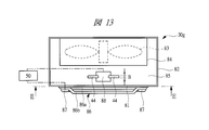
- the ion generator 30g according to the seventh embodiment shown in FIGS. 12 to 14 has an air supply casing 82 in which an air outlet 81 is formed.
- a fan case 84 in which an axial flow type fan 83 is incorporated is disposed inside the housing 82, and the fan 83 is an electric motor (not shown) disposed on the back side of the housing 82. It is rotationally driven by a motor.
- the fan 83 is driven to rotate, air flows from the outside into an air inlet formed on the back side of the casing 82, and the air that has flowed in is discharged from the air outlet 81, and enters the casing 82 from the outside.
- An air supply path 85 for guiding the air to the air outlet 81 is formed.
- a conductive member 86 having a hole through which air passes so as to cover the air outlet 81 is attached to the housing 82, and the conductive member 86 constitutes a counter electrode.
- the conductive member 86 has a plurality of concentric annular portions 86 a and a plurality of support legs 86 b fixed to the annular portions 86 a, and the base ends of the support legs 86 b are fixed to the housing 82 by screw members 87. Has been. Air discharged from the air outlet 81 is discharged to the outside through a gap between the conductive members 86.
- an electrode holder 88 is disposed in the housing 82 so as to face the center of the air outlet 81, and is fixed to the housing 82 by a support member (not shown). Yes.
- Four discharge electrodes 44 made of a flexible member are radially attached to the electrode holder 88 so as to protrude radially outward, and each discharge electrode 44 has a base end portion, that is, a fixed end 44a.
- the electrode holder 88 is fixed.
- the discharge electrode 44 extends parallel to the inside of the conductive member 86 with respect to the conductive member 86 serving as a counter electrode, and extends in a direction across the air guided into the housing 82.
- the conductive member 86 and the discharge electrode 44 are connected to the power supply unit 50 shown in FIG. 13, and a high voltage is supplied from the power supply unit 50 to the conductive member 86 and the discharge electrode 44.
- a high voltage is supplied from the power supply unit 50 to the conductive member 86 and the discharge electrode 44.
- the tip of the discharge electrode 44 is electrically connected to the discharge electrode 44. Corona discharge occurs between the conductive member 86 and the air flowing around the discharge electrode 44 is ionized by the corona discharge to generate air ions.
- each discharge electrode 44 has a proximal end portion fixed to an electrode holder 88 and a distal end portion that is a free end portion 44b.
- the width dimension B of the discharge electrode 44 in the air flow direction is larger than the thickness dimension C, and the cross section is rectangular.
- the free end portion of the discharge electrode 44 receives a repulsive force of corona discharge.
- the free end receives a repulsive force under the state of air flowing, the free end is in the direction along the conductive member 86, that is, the air flow toward the air outlet 81, as indicated by reference numeral T in FIG. Oscillates in a direction across.
- the discharge electrode 44 has a width dimension B of about 1 mm and a thickness dimension of about 50 ⁇ m.
- the tip of the discharge electrode 44 made of a flexible material swings or vibrates in a direction crossing the air flow as shown in FIG. 14, the air ions ionized by the corona discharge are absorbed by the electrode holder 88. Dispersed over a wide range along the circumferential direction. As shown in FIG. 14, when four discharge electrodes 44 are provided on the electrode holder 88 at intervals in the circumferential direction, the electrode holder 88 is widened over the entire circumferential direction outward in the radial direction. Air ions will be generated.
- the number of discharge electrodes 44 arranged in the housing 82 is not limited to four, but by arranging a plurality of about four discharge electrodes 44 as shown in the figure, air is discharged from the entire air outlet 81. Ions can be blown out. Thereby, the distribution density of the air ions discharged from the air outlet 81 is made uniform as a whole, and the surface of the object to be neutralized can be neutralized as a whole.
- the free end of the discharge electrode 44 swings or vibrates as described above, it is possible to prevent the dust from adhering to the discharge electrode 44 even if dust is contained in the air supplied from the outside. Since the swinging direction of the free end is a direction crossing the air flow, the distance between the object to be discharged disposed in front of the air outlet 81 and the discharge electrode 44 may change when air ions are generated. Absent. Thereby, the air ion of a fixed ionization density can always be sprayed with respect to a to-be-eliminated object.
- the discharge electrode 44 described above has a cross-sectional shape in which the width dimension B in the airflow direction is larger than the thickness dimension C, and is easily oscillated and deformed in the circumferential direction of the electrode holder 88, that is, in the direction crossing the airflow. Therefore, when a repulsive force is applied to the discharge electrode 44 during corona discharge, the free end of the discharge electrode 44 swings in a direction across the air flow. However, even if the cross-sectional shape of the discharge electrode 44 is circular or square, the free end can be swung in the above-described direction by the repulsive force during corona discharge and the pulsation of the air flow.
- the conductive member 86 covering the air outlet 81 is attached to the casing 82 so as to cover the air outlet 81, and can prevent an operator from inadvertently inserting a finger or the like into the casing 82. Moreover, since the conductive member 86 is in a direction crossing the air flow, the distance between the discharge electrode 44 and the conductive member 86 does not change when the free end swings in the direction crossing the air flow. Corona discharge can be stably generated in a constant state at all times. Furthermore, since the swinging direction of the discharge electrode 44 is a direction crossing the air flow, the distance between the fan case 84 and the conductive member 86 can be reduced, and the ion generator can be miniaturized.
- the four discharge electrodes 44 made of a flexible member are flown from the outer peripheral side of the air outlet 81 inward as in the case described above. It is arranged in a direction that crosses. Even when the discharge electrode 44 is arranged as shown in FIG. 17, the free end of the discharge electrode 44 is swung or vibrated in the same manner as the case where the discharge electrode 44 is arranged at the center of the air outlet 81 as described above. Can be made.
- two discharge electrodes 44 are arranged in parallel to each other on both the left and right sides of the air outlet 81, but discharge electrodes radially toward the center of the circular air outlet 81. 44 may be arranged. 15 to 17, the power supply unit 50 is not shown.
- the discharge electrode 44 is arranged at the center of the air outlet 81, and the discharge electrode 44 is arranged around the air outlet 81 as shown in FIGS. If it arrange
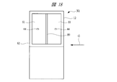
- two air outlets 81 partitioned by a partition wall 89 are formed.
- Two discharge electrodes 44 are arranged in the housing 82 so as to correspond to the respective air outlets 81.
- the discharge electrode 44 is disposed in the casing 82 in the direction along the air flow, that is, in the direction toward the air outlet 81, and the discharge electrode is discharged during corona discharge.
- the free end portion 44 swings in the vertical direction in FIG. 18, that is, in the direction crossing the air flow. As shown in FIG.
- the fan 83 is a multi-blade type, and the external air is introduced into the housing 82 from the side as shown by an arrow G in FIG.
- positioning form of a counter electrode you may make it attach a conductive member so that the air blower outlet 81 may be covered as mentioned above, and arrange
- FIG. 20 shows an ion generator 30j having a configuration in which a large number of air outlets 81 are provided in the casing 82.
- the discharge electrode 44 is arranged in a direction along the air flow, and the free end of the discharge electrode 44 swings in a direction crossing the air flow.
- Other structures are the same as those shown in FIGS.
- FIG. 21 is a cross-sectional view showing an ion generator 30k according to the eleventh embodiment, in which the discharge electrode 44 is swung in a direction along the air flow. Even if the free end is swung in this direction, the air ionized by corona discharge can be dispersed over a wide range. Considering the swing stroke, as is clear from comparison with FIG. 19, the dimension of the housing 82 in the left-right direction in FIG. 21 becomes longer, and the ion generator 30 k becomes larger. On the other hand, if the free end of the discharge electrode 44 is swung in a direction crossing the air flow, the dimensions of the air outlet 81 and the fan case 84 can be shortened, and the ion generator can be downsized. it can.
- FIG. 22A is a schematic diagram showing an air ion generation state by the oscillating discharge electrode 44
- FIG. 22B shows an air ion generation state by the fixed discharge electrode, that is, the discharge needle 61 shown as a comparative example.
- FIG. The distance d between the counter electrode 75 and the discharge electrode 44 is the same as the distance d between the counter electrode 75 and the discharge needle 61 of the comparative example.
- an arrow indicates a generation range of air ions
- a symbol EI indicates a distribution state of air ions generated by corona discharge between the counter electrode and the discharge electrode.
- FIG. 22A when the free end of the discharge electrode 44 swings across the air flow, air ions EI can be generated in a wide range.
- FIG. 22B when a fixed discharge electrode, that is, the discharge needle 61 is used, the range in which air ions are generated is narrow.
- the fan 83 is incorporated in the housing 82, but air is not supplied from the outside of the housing 82 without providing a blower or fan in the housing 82. May be supplied.
- the casing 82 has a configuration in which only the discharge electrode 44 is provided in the air supply path 85 that guides the air supplied from the outside to the air outlet 81.
- the discharge electrode 44 is made of a titanium alloy.
- the present invention is not limited to this, and depending on the charge removal capability (specification) of the ion generator, Discharge electrodes made of other conductive materials such as stainless steel can also be used.
- each discharge electrode 44 has been described as generating positive air ions EI.
- the present invention is not limited to this, and the state of charge of the object to be neutralized (positive / negative) ), Negative air ions EI can be generated by the discharge electrodes 44, or positive or negative air ions EI can be alternately generated by the discharge electrodes 44.
- the ion generator of the present invention can be applied to remove static electricity charged on a packaging film.
Landscapes
- Engineering & Computer Science (AREA)
- Physics & Mathematics (AREA)
- Plasma & Fusion (AREA)
- Chemical & Material Sciences (AREA)
- Combustion & Propulsion (AREA)
- General Physics & Mathematics (AREA)
- Elimination Of Static Electricity (AREA)
Priority Applications (2)
| Application Number | Priority Date | Filing Date | Title |
|---|---|---|---|
| US14/381,460 US20150123008A1 (en) | 2012-03-08 | 2012-11-08 | Ion generator |
| KR20147024173A KR20140117656A (ko) | 2012-03-08 | 2012-11-08 | 이온 발생 장치 |
Applications Claiming Priority (2)
| Application Number | Priority Date | Filing Date | Title |
|---|---|---|---|
| JP2012-051793 | 2012-03-08 | ||
| JP2012051793A JP5830414B2 (ja) | 2012-03-08 | 2012-03-08 | イオン発生装置 |
Publications (1)
| Publication Number | Publication Date |
|---|---|
| WO2013132694A1 true WO2013132694A1 (ja) | 2013-09-12 |
Family
ID=49116196
Family Applications (1)
| Application Number | Title | Priority Date | Filing Date |
|---|---|---|---|
| PCT/JP2012/079013 Ceased WO2013132694A1 (ja) | 2012-03-08 | 2012-11-08 | イオン発生装置 |
Country Status (4)
| Country | Link |
|---|---|
| US (1) | US20150123008A1 (https=) |
| JP (1) | JP5830414B2 (https=) |
| KR (1) | KR20140117656A (https=) |
| WO (1) | WO2013132694A1 (https=) |
Families Citing this family (3)
| Publication number | Priority date | Publication date | Assignee | Title |
|---|---|---|---|---|
| US11453204B2 (en) * | 2019-09-10 | 2022-09-27 | Advanced Copper Foil Inc. | Poly-supported copper foil |
| US12261416B2 (en) * | 2021-06-04 | 2025-03-25 | Illinois Tool Works Inc. | Ionizer emitter nozzles |
| WO2022256616A1 (en) * | 2021-06-04 | 2022-12-08 | Illinois Tool Works Inc. | Ionizer emitter nozzles |
Citations (6)
| Publication number | Priority date | Publication date | Assignee | Title |
|---|---|---|---|---|
| JPS5662268A (en) * | 1979-10-10 | 1981-05-28 | Oce Nederland Bv | Corona unit |
| JPH04135937U (ja) * | 1991-06-07 | 1992-12-17 | 春日電機株式会社 | コロナ放電処理装置 |
| JPH0922770A (ja) * | 1995-07-06 | 1997-01-21 | Shin Etsu Polymer Co Ltd | コロナ放電用電極およびその製造方法 |
| JP2006049227A (ja) * | 2004-08-09 | 2006-02-16 | Kyoritsu Denki Sangyo Kk | 放電用電極 |
| JP2011060537A (ja) * | 2009-09-09 | 2011-03-24 | Three M Innovative Properties Co | 除電装置 |
| WO2012090550A1 (ja) * | 2010-12-28 | 2012-07-05 | 株式会社コガネイ | イオン発生装置 |
Family Cites Families (1)
| Publication number | Priority date | Publication date | Assignee | Title |
|---|---|---|---|---|
| US3729649A (en) * | 1972-05-25 | 1973-04-24 | Eastman Kodak Co | Corona charging apparatus |
-
2012
- 2012-03-08 JP JP2012051793A patent/JP5830414B2/ja not_active Expired - Fee Related
- 2012-11-08 KR KR20147024173A patent/KR20140117656A/ko not_active Ceased
- 2012-11-08 WO PCT/JP2012/079013 patent/WO2013132694A1/ja not_active Ceased
- 2012-11-08 US US14/381,460 patent/US20150123008A1/en not_active Abandoned
Patent Citations (6)
| Publication number | Priority date | Publication date | Assignee | Title |
|---|---|---|---|---|
| JPS5662268A (en) * | 1979-10-10 | 1981-05-28 | Oce Nederland Bv | Corona unit |
| JPH04135937U (ja) * | 1991-06-07 | 1992-12-17 | 春日電機株式会社 | コロナ放電処理装置 |
| JPH0922770A (ja) * | 1995-07-06 | 1997-01-21 | Shin Etsu Polymer Co Ltd | コロナ放電用電極およびその製造方法 |
| JP2006049227A (ja) * | 2004-08-09 | 2006-02-16 | Kyoritsu Denki Sangyo Kk | 放電用電極 |
| JP2011060537A (ja) * | 2009-09-09 | 2011-03-24 | Three M Innovative Properties Co | 除電装置 |
| WO2012090550A1 (ja) * | 2010-12-28 | 2012-07-05 | 株式会社コガネイ | イオン発生装置 |
Also Published As
| Publication number | Publication date |
|---|---|
| KR20140117656A (ko) | 2014-10-07 |
| US20150123008A1 (en) | 2015-05-07 |
| JP2013187063A (ja) | 2013-09-19 |
| JP5830414B2 (ja) | 2015-12-09 |
Similar Documents
| Publication | Publication Date | Title |
|---|---|---|
| JP4308610B2 (ja) | イオン発生装置 | |
| CN103736610B (zh) | 静电涂装装置 | |
| WO2012090550A1 (ja) | イオン発生装置 | |
| JP4594111B2 (ja) | 除電装置および放電モジュール | |
| JP4540043B2 (ja) | コロナ放電型イオナイザ | |
| CN101132862A (zh) | 静电涂敷装置 | |
| JP5830414B2 (ja) | イオン発生装置 | |
| WO2007119751A1 (ja) | 除電装置および放電モジュール | |
| JP2010516459A (ja) | コロナ電極における粉塵の凝集を防止する方法及び装置 | |
| CN104364016B (zh) | 静电涂装装置 | |
| JP6434675B2 (ja) | 静電塗装機 | |
| CN104349843A (zh) | 静电涂装装置 | |
| TWI592061B (zh) | Electrostatic elimination device | |
| JP5539848B2 (ja) | イオン生成装置 | |
| JP5775890B2 (ja) | 回転霧化頭型塗装装置 | |
| JP2008178235A (ja) | プラズマモータ | |
| US20060153980A1 (en) | Method for coating objects, electrode arrangement, and coating system | |
| JP2018104730A (ja) | 溶射システム | |
| JP2004114042A (ja) | 超音波定常波アトマイザ装置 | |
| JP2024037628A (ja) | 除電装置 | |
| JP2005000785A (ja) | 静電粉体塗装装置 | |
| JP2020102417A (ja) | 除電装置 |
Legal Events
| Date | Code | Title | Description |
|---|---|---|---|
| 121 | Ep: the epo has been informed by wipo that ep was designated in this application |
Ref document number: 12870719 Country of ref document: EP Kind code of ref document: A1 |
|
| NENP | Non-entry into the national phase |
Ref country code: DE |
|
| WWE | Wipo information: entry into national phase |
Ref document number: 14381460 Country of ref document: US |
|
| ENP | Entry into the national phase |
Ref document number: 20147024173 Country of ref document: KR Kind code of ref document: A |
|
| 122 | Ep: pct application non-entry in european phase |
Ref document number: 12870719 Country of ref document: EP Kind code of ref document: A1 |