WO2013129422A1 - Dispositif d'émission radio, dispositif de réception radio et procédé de transmission de données - Google Patents
Dispositif d'émission radio, dispositif de réception radio et procédé de transmission de données Download PDFInfo
- Publication number
- WO2013129422A1 WO2013129422A1 PCT/JP2013/055012 JP2013055012W WO2013129422A1 WO 2013129422 A1 WO2013129422 A1 WO 2013129422A1 JP 2013055012 W JP2013055012 W JP 2013055012W WO 2013129422 A1 WO2013129422 A1 WO 2013129422A1
- Authority
- WO
- WIPO (PCT)
- Prior art keywords
- symbol
- transmission
- time
- propagation path
- unit
- Prior art date
Links
Images


Classifications
-
- H—ELECTRICITY
- H04—ELECTRIC COMMUNICATION TECHNIQUE
- H04B—TRANSMISSION
- H04B7/00—Radio transmission systems, i.e. using radiation field
- H04B7/02—Diversity systems; Multi-antenna system, i.e. transmission or reception using multiple antennas
- H04B7/04—Diversity systems; Multi-antenna system, i.e. transmission or reception using multiple antennas using two or more spaced independent antennas
- H04B7/06—Diversity systems; Multi-antenna system, i.e. transmission or reception using multiple antennas using two or more spaced independent antennas at the transmitting station
- H04B7/0697—Diversity systems; Multi-antenna system, i.e. transmission or reception using multiple antennas using two or more spaced independent antennas at the transmitting station using spatial multiplexing
-
- H—ELECTRICITY
- H04—ELECTRIC COMMUNICATION TECHNIQUE
- H04B—TRANSMISSION
- H04B7/00—Radio transmission systems, i.e. using radiation field
- H04B7/02—Diversity systems; Multi-antenna system, i.e. transmission or reception using multiple antennas
- H04B7/04—Diversity systems; Multi-antenna system, i.e. transmission or reception using multiple antennas using two or more spaced independent antennas
- H04B7/06—Diversity systems; Multi-antenna system, i.e. transmission or reception using multiple antennas using two or more spaced independent antennas at the transmitting station
- H04B7/0613—Diversity systems; Multi-antenna system, i.e. transmission or reception using multiple antennas using two or more spaced independent antennas at the transmitting station using simultaneous transmission
- H04B7/0667—Diversity systems; Multi-antenna system, i.e. transmission or reception using multiple antennas using two or more spaced independent antennas at the transmitting station using simultaneous transmission of delayed versions of same signal
- H04B7/0669—Diversity systems; Multi-antenna system, i.e. transmission or reception using multiple antennas using two or more spaced independent antennas at the transmitting station using simultaneous transmission of delayed versions of same signal using different channel coding between antennas
-
- H—ELECTRICITY
- H04—ELECTRIC COMMUNICATION TECHNIQUE
- H04L—TRANSMISSION OF DIGITAL INFORMATION, e.g. TELEGRAPHIC COMMUNICATION
- H04L1/00—Arrangements for detecting or preventing errors in the information received
- H04L1/02—Arrangements for detecting or preventing errors in the information received by diversity reception
- H04L1/06—Arrangements for detecting or preventing errors in the information received by diversity reception using space diversity
- H04L1/0618—Space-time coding
- H04L1/0625—Transmitter arrangements
-
- H—ELECTRICITY
- H04—ELECTRIC COMMUNICATION TECHNIQUE
- H04L—TRANSMISSION OF DIGITAL INFORMATION, e.g. TELEGRAPHIC COMMUNICATION
- H04L1/00—Arrangements for detecting or preventing errors in the information received
- H04L1/02—Arrangements for detecting or preventing errors in the information received by diversity reception
- H04L1/06—Arrangements for detecting or preventing errors in the information received by diversity reception using space diversity
- H04L1/0618—Space-time coding
- H04L1/0631—Receiver arrangements
-
- H—ELECTRICITY
- H04—ELECTRIC COMMUNICATION TECHNIQUE
- H04L—TRANSMISSION OF DIGITAL INFORMATION, e.g. TELEGRAPHIC COMMUNICATION
- H04L27/00—Modulated-carrier systems
- H04L27/32—Carrier systems characterised by combinations of two or more of the types covered by groups H04L27/02, H04L27/10, H04L27/18 or H04L27/26
- H04L27/34—Amplitude- and phase-modulated carrier systems, e.g. quadrature-amplitude modulated carrier systems
- H04L27/3405—Modifications of the signal space to increase the efficiency of transmission, e.g. reduction of the bit error rate, bandwidth, or average power
- H04L27/3416—Modifications of the signal space to increase the efficiency of transmission, e.g. reduction of the bit error rate, bandwidth, or average power in which the information is carried by both the individual signal points and the subset to which the individual points belong, e.g. using coset coding, lattice coding, or related schemes
-
- H—ELECTRICITY
- H04—ELECTRIC COMMUNICATION TECHNIQUE
- H04L—TRANSMISSION OF DIGITAL INFORMATION, e.g. TELEGRAPHIC COMMUNICATION
- H04L1/00—Arrangements for detecting or preventing errors in the information received
- H04L1/02—Arrangements for detecting or preventing errors in the information received by diversity reception
- H04L1/06—Arrangements for detecting or preventing errors in the information received by diversity reception using space diversity
- H04L1/0618—Space-time coding
- H04L1/0637—Properties of the code
- H04L1/0668—Orthogonal systems, e.g. using Alamouti codes
Definitions
- the present invention relates to a wireless transmission device, a wireless reception device, and a data transmission method that transmit and receive signals using a plurality of antennas.
- fading mainly due to movement deteriorates wireless communication quality.
- multiple antennas are placed in a terminal or base station so that the correlation of propagation path fluctuations of each antenna is low, and the fact that propagation path fluctuations between antennas differ makes fading
- a space-time coded transmission diversity scheme that suppresses power reduction due to CDMA is known.
- a code based on differential coding that can follow high-speed channel fluctuations compared to the synchronous detection method by generating symbols using the transmission information corresponding to the transmission bits between consecutive symbols as the amount of change in the phase space.
- Japanese Patent Application Laid-Open No. 2004-228688 discloses differential space-time coding transmission diversity in which conversion is made to correspond to space-time coding.
- the present invention has been made in view of the above, and provides a wireless transmission device, a wireless reception device, and a data transmission method that are free from restrictions on mapping to a start symbol and that can reduce the amount of calculation on the reception side.
- the purpose is to obtain.
- the present invention includes a plurality of transmitting antennas, start symbol generating means for generating a start symbol as a reference signal at the time of starting differential encoding, and information bits.
- Differential encoding means for differentially encoding the transmitted symbol to generate a differential symbol, and space-time encoding of the start symbol or the differential symbol to generate a signal to be transmitted from each transmission antenna
- a space-time encoding unit wherein the differential encoding unit generates the differential generated by the current differential encoding process based on the power of the start symbol or the power of the post-differentiation symbol generated previously. The power of the converted symbol is determined.
- the present invention it is possible to obtain a transmission diversity effect by space-time coding and to cope with differential coding for symbols having different amplitudes.
- demodulation can be performed with simple processing regardless of whether the multi-level number of symbols and the amplitude of transmission symbols are constant, and the amount of calculation can be suppressed low.
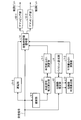
- FIG. 1 is a diagram illustrating a configuration example of a modulation unit according to the first embodiment.
- FIG. 2 is a diagram illustrating a configuration example of the demodulation unit according to the first embodiment.
- FIG. 3 is a diagram showing 64QAM signal points.
- FIG. 4 is a diagram illustrating a configuration example of a demodulation unit according to the second embodiment.
- FIG. 5 is a diagram illustrating a configuration example of a demodulation unit according to the third embodiment.
- FIG. 1 is a diagram illustrating a configuration example of a modulation unit included in a wireless transmission device of a wireless communication system according to Embodiment 1.
- FIG. FIG. 2 is a diagram illustrating a configuration example of a demodulation unit included in the wireless reception device of the wireless communication system according to the first embodiment.
- description of filters, amplifiers, frequency converters, analog / digital converters, digital / analog converters, and the like that are necessary as a wireless transmission / reception device is omitted.
- the wireless transmission device constitutes a transmission-side communication device, and the wireless reception device constitutes a reception-side communication device.
- the wireless transmission device includes two transmission antennas (transmission antennas # 1 and # 2), and the wireless reception device includes one reception antenna.
- the modulation unit maps mapping bits 1-1 and 1-2 that map a transmission bit string to an arbitrary point on a phase space to generate and output a transmission symbol, and performs differential encoding. Differential using a start symbol generation unit 2 that generates a start symbol of the transmission symbol, a transmission symbol that has been differentially encoded in the past, or a transmission symbol that is input from the start symbol and the mapping units 1-1 and 1-2.
- a differential encoding unit 3 that performs encoding, a start symbol output from the start symbol generation unit 2, and a transmission symbol (differentiated symbol) after differential output from the differential encoding unit 3
- the signal selection unit 4 that selects and outputs one of them, the delay unit 5 that delays the transmission signal that is the signal output from the signal selection unit 4, and the power of the transmission signal delayed by the delay unit 5 are calculated.
- a space-time coding unit 8 that performs space-time coding, a pilot generation unit 9 that generates a pilot signal, a pilot antenna and a transmission signal after space-time coding are switched, and a transmission antenna # 1 that is not shown
- a transmission signal switching unit 10 that outputs a signal to be transmitted from each of # 2.
- the differential encoding unit 3, the transmission signal power calculation unit 6, and the 1 / square root calculation unit 7 operate as differential encoding means.
- the demodulation unit delays reception signals received by a reception antenna (not shown), delay units 5-1 and 5-2, and a reception signal output from the delay unit 5-1 ( A received signal power calculation unit 11 that calculates the power of the received signal after delay), and a one-square-root calculation unit 7 that calculates 1-square root of the received signal power output from the received signal power calculation unit 11- 1 and the same pilot generation unit 9 as that included in the transmission unit of FIG.
- a propagation path estimation unit 12 that estimates (amplitude fluctuation amount or phase and amplitude fluctuation amount), a propagation path gain calculation unit 13 that calculates a propagation path gain from the propagation path response estimated by the propagation path estimation unit 12, and Calculated by the propagation path gain calculation unit 13
- the differential space-time decoding operation is performed by using the calculation result in the square root 1 calculation unit 7-2 for calculating 1 / square root of the propagation path gain and the received signal and the square root 1 calculation unit 7-1.
- the differential space-time decoding unit 14 to be performed, and two differential space-time decoding signals that are output signals from the differential space-time decoding unit 14 are converted into transmission bit estimation values based on signal point positions in the phase space.
- Demapping units 15-1 and 15-2 that convert and output as demodulated bits. Note that the delay units 5-1 and 5-2, the square root 1 computation units 7-1 and 7-2, the received signal power calculation unit 11, the propagation path estimation unit 12, the propagation path gain calculation unit 13, and the differential space-time The decoding unit 14 operates as transmission symbol estimation means.
- mapping units 1-1 and 1-2 divide the input transmission bit string into combinations of 1 bit or more, and the combination of the divided bit strings and the arrangement points in the I / Q quadrature phase space correspond one-to-one.
- the I / Q amplitude value of the mapping point (a point on the I / Q quadrature phase space having the I / Q amplitude is called a symbol) is output as a transmission symbol.
- mapping the transmission bit string is divided into combinations of every 6 bits, and 64 QAM (Quadrature Amplitude) in which the transmission bit string of every 6 bits is arranged at 64 mapping points when the minimum distance between the mapping points is A.
- QAM Quadrature Amplitude
- the case of (Modulation) is shown in FIG. In this way, the power value need not be constant for the mapping point, and a plurality of power values may be taken.
- other mapping arrangements such as 32QAM, 16QAM, and QPSK (Quadrature Phase Shift Keying) other than 64QAM may be used.
- the generated pilot signal is a signal for measuring the propagation path fluctuation between the transmission antenna # 1 and the reception antenna and the propagation path fluctuation between the transmission antenna # 2 and the reception antenna on the reception side.
- the pilot signals transmitted from both transmit antennas are preferably orthogonal by frequency, time or code, or any combination thereof.
- the transmission signal switching unit 10 selects and outputs the pilot signal for each transmission antenna generated by the pilot generation unit 9 as the transmission signal for the transmission antennas # 1 and # 2.
- a transmission signal (pilot signal) output from the transmission signal switching unit 10 is transmitted from the transmission antenna.
- the start symbol may be a mapping point on the I / Q quadrature phase space used in mapping by the mapping unit 1 or may be an arbitrary I / Q amplitude value not used in mapping by the mapping unit 1. However, it is assumed that the two start symbols are not 0 (one power may be 0).
- the signal selector 4 selects and outputs the two start symbols x 0 and x 1 output from the start symbol generator 2.
- the start symbol selected by the signal selection unit 4 is input to the space-time encoding unit 8 and the delay unit 5.
- space-time coding using two time slots is performed on two symbol inputs, but space-time coding using two or more time slots may be performed.
- the delay unit 5 delays the signal output from the signal selection unit 4 by the number of time slots used in the space-time coding by the space-time coding unit 8. That is, in this embodiment, the delay is performed by two time slots.
- the transmission signal power calculation unit 6 calculates a power sum
- the 1 / square root computing unit 7 calculates 1 / sqrt (
- the differential encoding unit 3 applies the following equations (1-1) and (1) to the transmission symbols s 2 and s 3 generated by the mapping units 1-1 and 1-2. -2), and the post-differentiation symbols x 2 and x 3 obtained as a result are output.
- 1 / sqrt (
- the outputs x i + 1 at time t i + 1, as a transmission antenna # 2 signal
- start symbols may be inserted periodically in units of.
- the signal output from the modulation unit described above is transmitted from the transmission antennas # 1 and # 2, passes through the propagation path, and is input as a reception signal to the demodulation unit at the same time.
- the pilot generation unit 9 generates a pilot signal common to the modulation unit (the same pilot signal as that generated by the pilot generation unit 9 of the modulation unit).
- the propagation path response C 1 between the transmission antenna # 1 and the reception antenna and the propagation path response C 2 between the transmission antenna # 2 and the reception antenna are calculated independently.
- the amplitude and phase of the output channel response may be an I / Q amplitude value in an I / Q orthogonal space or may be expressed by a phase rotation angle and an amplitude.
- the channel responses C 1 and C 2 calculated by the channel estimating unit 12 are input to the channel gain calculating unit 13, and the channel gain calculating unit 13 sums the channel gains
- 2 is calculated.
- the sum of the propagation path gains calculated by the propagation path gain calculation unit 13 is input to the 1 / square root calculation unit 7-2, and the 1 / square root calculation unit 7-2 calculates the sum of the input propagation path gains.
- 2 ) is calculated.
- the calculation result is input to the differential space-time decoding unit 14.
- the received signals r 0 and r 1 are input to the delay units 5-1 and 5-2, and the delay units 5-1 and 5-2 are used for space-time coding in the space-time coding unit 8 of the modulation unit. Is delayed by the number of time slots (in this embodiment, there are two time slots).
- reception signals r 0 and r 1 delayed by the delay unit 5-1 are input to the reception signal power calculation unit 11, and the reception signal power calculation unit 11 receives the reception signal power sum
- 2 is calculated.
- the square root one computing unit 7-1 is one square root of the received signal power sum
- the receiving antennas receive the signals r 2 and r 3 .
- the received signal at each time can be expressed as the following equation (2) using the transmission line responses C 1 and C 2 . Note that noise is omitted in Equation (2).
- the estimated transmission symbol s is calculated based on the output 1 / sqrt (
- the outputs (decoding results) of the differential space-time decoding unit 14 obtained by the equations (3-1) and (3-2) are input to the demapping units 15-1 and 15-2, and the demapping unit 15- 1 and 15-2 confirm the decoding result, and convert it into a bit string on the assumption that the closest mapping point in the transmission mapping point arrangement is transmitted (restore the transmitted bit string).
- Received signals r 2 and r 3 delayed at delay unit 5-2, received signals r 4 and r 5 received at times t 4 and 5, and output 1 / one of square root 1 arithmetic unit 7-1 sqrt (
- both non-zero powers one power may be 0
- non-zero predetermined start symbols and transmission symbols are differentially encoded
- a normalization coefficient is calculated based on the post-differentiation symbol obtained in the past differential coding processing, and differential
- the encoded symbol and the transmission symbol are differentially encoded, their power is normalized, and space-time encoding is performed to generate a transmission signal.
- demodulation can be performed with simple processing regardless of whether the multi-value number of symbols and the amplitude of transmission symbols are constant, and the amount of computation can be kept low.
- the differential encoding is performed by the above equations (1-1) and (1-2), there is no restriction on the start symbols x 0 and x 1 .
- the power of the start symbol is preferably equal to the average power of the transmission symbol.
- the case where the pilot signal is arranged at the head of the frame has been described. However, it is also possible to arrange the pilot signal once at the end of the frame, in the middle of the frame, or in two or more frames. is there.
- the modulation unit and demodulation unit do not use error correction coding and decoding (turbo code and decoding, LDPC code and decoding, convolutional coding and Viterbi decoding, Reed-Solomon coding and decoding, etc.), but the transmission bits of the modulation unit In addition, error correction encoding and decoding may be performed on the demodulated bits of the demodulation unit.
- FIG. FIG. 4 is a diagram illustrating a configuration example of a demodulation unit according to the second embodiment.
- a modification of the demodulation unit described in Embodiment 1 will be described.
- the same components as those of the demodulator (see FIG. 2) of the first embodiment are denoted by the same reference numerals.
- the modulation unit provided on the signal transmission side is the same as in the first embodiment.
- the demodulating unit of the present embodiment is obtained by replacing the square root 1 arithmetic units 7-1 and 7-2 included in the demodulator of the first embodiment with a multiplying unit 16 and a square root 1 arithmetic unit 17. is there.
- the multiplication unit 16 multiplies the reception signal power calculated by the reception signal power calculation unit 11 and the propagation channel gain calculated by the propagation channel gain calculation unit 13, and calculates 1 / square root of the multiplication result.
- the unit 17 calculates.
- the calculation result is input to the differential space-time decoding unit 14.
- the square root of each of the received signal power calculated by the received signal power calculating unit 11 and the channel gain calculated by the channel gain calculating unit 13 is square root.
- the one-minute arithmetic units 7-1 and 7-2 calculate and multiply the calculation result in the differential space-time decoding unit 14.
- the demodulator of the present embodiment as shown in FIG. 4, after multiplying the output of the received signal power calculator 11 and the output of the propagation path gain calculator 13 by the multiplier 16, the square root
- the 1 / square calculation unit 17 calculates 1 / square root.
- FIG. 5 is a diagram illustrating a configuration example of a demodulation unit according to the third embodiment. Similar to the second embodiment, a modification of the demodulation unit described in the first embodiment will be described. In FIG. 5, the same reference numerals are given to the same constituent elements as those of the demodulator (see FIG. 2) of the first embodiment. In the present embodiment, only portions different from those in the first embodiment will be described.
- the modulation unit provided on the signal transmission side is the same as in the first embodiment.
- the demodulation unit of the present embodiment is obtained by adding interpolation delay units 18-1 and 18-2 and an interpolation unit 19 to the demodulation unit of the first embodiment.
- Interpolation delay units 18-1 and 18-2 delay the input signal for a predetermined time before outputting.
- the interpolation unit 19 performs an interpolation process on the output from the square root 1 computation unit 7-2 (1/1 of the square root of the propagation path gain).
- the square root of each of the received signal power calculated by the received signal power calculator 11 and the square root of each of the channel gains calculated by the channel gain calculator 13 is obtained.
- the one-minute arithmetic units 7-1 and 7-2 calculate and multiply the calculation result in the differential space-time decoding unit 14.
- 2 ) is input to the interpolation unit 19 and the interpolation delay unit 18.
- the operation of the demodulation unit of this embodiment will be described in detail, assuming that the pilot signal is arranged at the head of the frame. To do.
- C 1 1 a channel response between the transmission antenna # 1 and receiving antenna in the first frame (to ze shown), when the channel response C 2 1 between the transmission antennas # 2 and the receiving antenna, the square root One of the square roots of the propagation path gain, ie, 1 / sqrt (
- the square root component is obtained.
- the interpolator 19 calculates 1 / sqrt (
- 2 ) is used to calculate the gain variation in the first frame by interpolation.
- an interpolation method used at this time for example, linear interpolation or polynomial interpolation can be considered.
- the channel gains during the transmission of the two pilot signals are interpolated using the channel gains obtained based on the two pilot signals, respectively. May be used for interpolation or averaging.
- the interpolating delay unit 18-2 delays the output of the one-square-root computing unit 7-1, the output of the delay unit 5-2, and the received signal by a time slot of one frame.
- the demodulation performance can be improved under the condition that the transmission path gain fluctuates greatly in the frame. .
- the demodulating unit of the first embodiment is modified to obtain a transmission line gain using two or more pilot signals (a transmission line gain in a section where no pilot signal is transmitted is obtained by interpolation processing).
- the demodulation unit of the second embodiment can be similarly modified.
- each receiving antenna there is one receiving antenna on the receiving side.
- a plurality of receiving antennas may be used, and diversity reception of signals received by each receiving antenna may be performed.
- the wireless transmission device is useful for a wireless communication system to which differential encoding is applied.
Abstract
Priority Applications (5)
| Application Number | Priority Date | Filing Date | Title |
|---|---|---|---|
| CN201380011919.4A CN104145462B (zh) | 2012-03-02 | 2013-02-26 | 无线发送装置、无线接收装置以及数据传送方法 |
| EP13755427.5A EP2822245B1 (fr) | 2012-03-02 | 2013-02-26 | Dispositif d'émission radio, dispositif de réception radio et procédé de transmission de données |
| BR112014019008-9A BR112014019008B1 (pt) | 2012-03-02 | 2013-02-26 | Aparelhos de radiotransmissão e de radiorrecepção, e, método para transmissão de dados |
| US14/372,786 US9154212B2 (en) | 2012-03-02 | 2013-02-26 | Radio transmission apparatus, radio reception apparatus, and data transmission method |
| JP2014502262A JP5697795B2 (ja) | 2012-03-02 | 2013-02-26 | 無線送信装置、無線受信装置およびデータ伝送方法 |
Applications Claiming Priority (2)
| Application Number | Priority Date | Filing Date | Title |
|---|---|---|---|
| JP2012046744 | 2012-03-02 | ||
| JP2012-046744 | 2012-03-02 |
Publications (1)
| Publication Number | Publication Date |
|---|---|
| WO2013129422A1 true WO2013129422A1 (fr) | 2013-09-06 |
Family
ID=49082619
Family Applications (1)
| Application Number | Title | Priority Date | Filing Date |
|---|---|---|---|
| PCT/JP2013/055012 WO2013129422A1 (fr) | 2012-03-02 | 2013-02-26 | Dispositif d'émission radio, dispositif de réception radio et procédé de transmission de données |
Country Status (6)
| Country | Link |
|---|---|
| US (1) | US9154212B2 (fr) |
| EP (1) | EP2822245B1 (fr) |
| JP (1) | JP5697795B2 (fr) |
| CN (1) | CN104145462B (fr) |
| BR (1) | BR112014019008B1 (fr) |
| WO (1) | WO2013129422A1 (fr) |
Cited By (2)
| Publication number | Priority date | Publication date | Assignee | Title |
|---|---|---|---|---|
| WO2019163001A1 (fr) * | 2018-02-20 | 2019-08-29 | 三菱電機株式会社 | Dispositif de transmission, et procédé de mappage de sous-porteuse |
| US11218252B2 (en) * | 2017-06-15 | 2022-01-04 | Mitsubishi Electric Corporation | Transmission device, receiving device, and wireless communication system |
Families Citing this family (5)
| Publication number | Priority date | Publication date | Assignee | Title |
|---|---|---|---|---|
| JP2013156159A (ja) | 2012-01-30 | 2013-08-15 | Seiko Instruments Inc | 電子時計 |
| US9716568B2 (en) * | 2013-09-26 | 2017-07-25 | Hitachi Kokusai Electric Inc. | Wireless communication system and transmitter |
| US9166628B2 (en) * | 2013-12-13 | 2015-10-20 | Alcatel Lucent | Use of parity-check coding for carrier-phase estimation in an optical transport system |
| EP3605907A4 (fr) * | 2017-05-10 | 2020-04-22 | Mitsubishi Electric Corporation | Dispositif de transmission, dispositif de station de base et système de communication sans fil |
| JP7218580B2 (ja) * | 2019-01-09 | 2023-02-07 | 横浜ゴム株式会社 | 空気入りタイヤの検査方法及び空気入りタイヤの検査装置 |
Citations (2)
| Publication number | Priority date | Publication date | Assignee | Title |
|---|---|---|---|---|
| WO2001084739A2 (fr) | 2000-05-02 | 2001-11-08 | At & T Corp. | Detection de differentiel d'antenne d'emission multiple a partir de conceptions orthogonales generalisees |
| WO2011105103A1 (fr) * | 2010-02-26 | 2011-09-01 | 株式会社日立国際電気 | Émetteur |
Family Cites Families (14)
| Publication number | Priority date | Publication date | Assignee | Title |
|---|---|---|---|---|
| US6891903B2 (en) | 1999-04-22 | 2005-05-10 | At&T Corp. | Multiple transmit antenna differential detection from generalized orthogonal designs |
| US7773699B2 (en) * | 2001-10-17 | 2010-08-10 | Nortel Networks Limited | Method and apparatus for channel quality measurements |
| US7649953B2 (en) * | 2003-02-13 | 2010-01-19 | Ntt Docomo, Inc. | Differential multiple-length transmit and reception diversity |
| KR100957344B1 (ko) * | 2003-04-25 | 2010-05-12 | 삼성전자주식회사 | 채널의 전력을 이용한 차등 공간-시간 블럭 부호의 송수신방법 및 장치 |
| US7302238B2 (en) * | 2003-04-25 | 2007-11-27 | Samsung Electronics Co., Ltd. | Transmit diversity system, method and computer program product |
| EP1768271B1 (fr) * | 2004-08-11 | 2018-12-12 | Panasonic Intellectual Property Management Co., Ltd. | Systeme de communication, dispositif de controle de la station de base et dispositif de la station de base |
| KR20080036493A (ko) * | 2006-10-23 | 2008-04-28 | 엘지전자 주식회사 | 이동통신 시스템에서의 망 접속 방법 및 이를 지원하는단말기 |
| CN101141199B (zh) * | 2007-02-28 | 2010-09-29 | 中兴通讯股份有限公司 | 一种光发送系统及其方法 |
| FR2928509B1 (fr) * | 2008-03-04 | 2011-01-14 | Commissariat Energie Atomique | Procede de codage spatio-temporel differentiel. |
| CN101841339B (zh) * | 2009-03-17 | 2015-05-06 | 电信科学技术研究院 | 一种编码器、译码器及编码、译码方法 |
| US8089916B2 (en) * | 2009-04-07 | 2012-01-03 | Indian Institute Of Science | Leveraging coherent distributed space-time codes for noncoherent communication in relay networks via training |
| US8731087B2 (en) * | 2009-06-30 | 2014-05-20 | Microsoft Corporation | Uplink MIMO transmission from mobile communications devices |
| WO2011105803A2 (fr) * | 2010-02-23 | 2011-09-01 | 엘지전자 주식회사 | Émetteur de signal de radiodiffusion, récepteur de signal de radiodiffusion, et procédé d'émission-réception de signal de radiodiffusion utilisant ceux-ci |
| JP5671328B2 (ja) * | 2010-12-21 | 2015-02-18 | 株式会社日立国際電気 | 受信装置、通信システム及び通信方法 |
-
2013
- 2013-02-26 WO PCT/JP2013/055012 patent/WO2013129422A1/fr active Application Filing
- 2013-02-26 EP EP13755427.5A patent/EP2822245B1/fr active Active
- 2013-02-26 BR BR112014019008-9A patent/BR112014019008B1/pt active IP Right Grant
- 2013-02-26 JP JP2014502262A patent/JP5697795B2/ja active Active
- 2013-02-26 US US14/372,786 patent/US9154212B2/en not_active Expired - Fee Related
- 2013-02-26 CN CN201380011919.4A patent/CN104145462B/zh active Active
Patent Citations (2)
| Publication number | Priority date | Publication date | Assignee | Title |
|---|---|---|---|---|
| WO2001084739A2 (fr) | 2000-05-02 | 2001-11-08 | At & T Corp. | Detection de differentiel d'antenne d'emission multiple a partir de conceptions orthogonales generalisees |
| WO2011105103A1 (fr) * | 2010-02-26 | 2011-09-01 | 株式会社日立国際電気 | Émetteur |
Non-Patent Citations (3)
| Title |
|---|
| See also references of EP2822245A4 |
| T. HIMSOON ET AL.: "Single-block differential transmit scheme for broadband wireless MIMO- OFDM systems", IEEE TRANSACTIONS ON SIGNAL PROCESSING, vol. 54, no. 9, September 2006 (2006-09-01), pages 3305 - 3314, XP055158046 * |
| YASUNORI KATO ET AL.: "B-8-3 Improvement of Robustness against Phase Noise with Differential Space-Time Block Code", THE INSTITUTE OF ELECTRONICS, INFORMATION AND COMMUNICATION ENGINEERS SOGO TAIKAI KOEN RONBUNSHU 2012 NEN TSUSHIN (2), 6 March 2012 (2012-03-06), pages 257, XP008173942 * |
Cited By (2)
| Publication number | Priority date | Publication date | Assignee | Title |
|---|---|---|---|---|
| US11218252B2 (en) * | 2017-06-15 | 2022-01-04 | Mitsubishi Electric Corporation | Transmission device, receiving device, and wireless communication system |
| WO2019163001A1 (fr) * | 2018-02-20 | 2019-08-29 | 三菱電機株式会社 | Dispositif de transmission, et procédé de mappage de sous-porteuse |
Also Published As
| Publication number | Publication date |
|---|---|
| US20150003554A1 (en) | 2015-01-01 |
| CN104145462B (zh) | 2017-03-01 |
| CN104145462A (zh) | 2014-11-12 |
| EP2822245B1 (fr) | 2018-10-24 |
| BR112014019008A8 (pt) | 2017-07-11 |
| US9154212B2 (en) | 2015-10-06 |
| JPWO2013129422A1 (ja) | 2015-07-30 |
| BR112014019008A2 (fr) | 2017-06-20 |
| EP2822245A1 (fr) | 2015-01-07 |
| JP5697795B2 (ja) | 2015-04-08 |
| BR112014019008B1 (pt) | 2022-07-26 |
| EP2822245A4 (fr) | 2015-11-04 |
Similar Documents
| Publication | Publication Date | Title |
|---|---|---|
| JP5697795B2 (ja) | 無線送信装置、無線受信装置およびデータ伝送方法 | |
| JP4975799B2 (ja) | 送信装置、送信方法、信号生成装置及び信号生成方法 | |
| US20040037262A1 (en) | Mobile communication system mult-icarrier cdma transmitting apparatus and multi-carrier cdma reception apparatus | |
| JP4470377B2 (ja) | 移動通信システムにおける伝搬路推定方法 | |
| JP2005184779A (ja) | 受信装置及び送信装置 | |
| RU2650179C2 (ru) | Устройство связи, устройство демодуляции, устройство восстановления несущей, устройство компенсации фазовой ошибки, способ компенсации фазовой ошибки и запоминающий носитель, на котором сохранена программа компенсации фазовой ошибки | |
| JP2008017144A (ja) | 無線受信装置および方法 | |
| JP6246426B2 (ja) | 送信装置および受信装置 | |
| JP2009049491A (ja) | 受信装置、受信方法及びプログラム | |
| US8837642B2 (en) | Methods and devices for estimating channel quality | |
| WO2016143863A1 (fr) | Dispositif de communication, procédé de démodulation, et programme | |
| JP4000067B2 (ja) | 受信方法および装置 | |
| JP6271931B2 (ja) | 無線受信装置 | |
| JP2012124954A (ja) | 受信装置及び受信方法 | |
| KR101232132B1 (ko) | 직교주파수분할다중접속 시스템을 위한 안테나 다이버시티 획득 장치 및 방법 | |
| JP5478327B2 (ja) | モジュロ演算で生成された信号を送受信する無線通信システム、受信機、及び、復調方法 | |
| JP5893773B1 (ja) | 受信方法および受信装置 | |
| KR100854635B1 (ko) | 연판정 입력 메트릭 산출 장치 및 방법과, 이를 이용한수신 심볼 복조 장치 및 방법 | |
| JP5419146B2 (ja) | 復調装置及び復調処理方法 | |
| JP6498632B2 (ja) | 通信システムおよび通信方法 | |
| JP4672047B2 (ja) | 通信端末の通信方法及び通信端末 | |
| JP2013207524A (ja) | ダイバーシチ受信機 | |
| JP2015186246A (ja) | 通信システム、送信機、受信機 | |
| JP2014039088A (ja) | 無線通信装置 | |
| JP2014050040A (ja) | 時空間トレリス符号化mimo送信装置及び受信装置 |
Legal Events
| Date | Code | Title | Description |
|---|---|---|---|
| 121 | Ep: the epo has been informed by wipo that ep was designated in this application |
Ref document number: 13755427 Country of ref document: EP Kind code of ref document: A1 |
|
| ENP | Entry into the national phase |
Ref document number: 2014502262 Country of ref document: JP Kind code of ref document: A |
|
| WWE | Wipo information: entry into national phase |
Ref document number: 14372786 Country of ref document: US |
|
| WWE | Wipo information: entry into national phase |
Ref document number: 2013755427 Country of ref document: EP |
|
| REG | Reference to national code |
Ref country code: BR Ref legal event code: B01A Ref document number: 112014019008 Country of ref document: BR |
|
| NENP | Non-entry into the national phase |
Ref country code: DE |
|
| ENP | Entry into the national phase |
Ref document number: 112014019008 Country of ref document: BR Kind code of ref document: A2 Effective date: 20140731 |