WO2013129402A1 - 電子機器用ガラス及び携帯機器保護用ガラス - Google Patents
電子機器用ガラス及び携帯機器保護用ガラス Download PDFInfo
- Publication number
- WO2013129402A1 WO2013129402A1 PCT/JP2013/054969 JP2013054969W WO2013129402A1 WO 2013129402 A1 WO2013129402 A1 WO 2013129402A1 JP 2013054969 W JP2013054969 W JP 2013054969W WO 2013129402 A1 WO2013129402 A1 WO 2013129402A1
- Authority
- WO
- WIPO (PCT)
- Prior art keywords
- glass
- thick
- protecting
- chemical strengthening
- central region
- Prior art date
- Legal status (The legal status is an assumption and is not a legal conclusion. Google has not performed a legal analysis and makes no representation as to the accuracy of the status listed.)
- Ceased
Links
Images



Classifications
-
- C—CHEMISTRY; METALLURGY
- C03—GLASS; MINERAL OR SLAG WOOL
- C03C—CHEMICAL COMPOSITION OF GLASSES, GLAZES OR VITREOUS ENAMELS; SURFACE TREATMENT OF GLASS; SURFACE TREATMENT OF FIBRES OR FILAMENTS MADE FROM GLASS, MINERALS OR SLAGS; JOINING GLASS TO GLASS OR OTHER MATERIALS
- C03C21/00—Treatment of glass, not in the form of fibres or filaments, by diffusing ions or metals in the surface
- C03C21/001—Treatment of glass, not in the form of fibres or filaments, by diffusing ions or metals in the surface in liquid phase, e.g. molten salts, solutions
- C03C21/002—Treatment of glass, not in the form of fibres or filaments, by diffusing ions or metals in the surface in liquid phase, e.g. molten salts, solutions to perform ion-exchange between alkali ions
-
- C—CHEMISTRY; METALLURGY
- C03—GLASS; MINERAL OR SLAG WOOL
- C03C—CHEMICAL COMPOSITION OF GLASSES, GLAZES OR VITREOUS ENAMELS; SURFACE TREATMENT OF GLASS; SURFACE TREATMENT OF FIBRES OR FILAMENTS MADE FROM GLASS, MINERALS OR SLAGS; JOINING GLASS TO GLASS OR OTHER MATERIALS
- C03C3/00—Glass compositions
- C03C3/04—Glass compositions containing silica
- C03C3/076—Glass compositions containing silica with 40% to 90% silica, by weight
- C03C3/083—Glass compositions containing silica with 40% to 90% silica, by weight containing aluminium oxide or an iron compound
- C03C3/085—Glass compositions containing silica with 40% to 90% silica, by weight containing aluminium oxide or an iron compound containing an oxide of a divalent metal
- C03C3/087—Glass compositions containing silica with 40% to 90% silica, by weight containing aluminium oxide or an iron compound containing an oxide of a divalent metal containing calcium oxide, e.g. common sheet or container glass
Definitions
- the present invention relates to glass for electronic devices and glass for portable devices.
- the edge of glass tends to be subjected to a strong impact due to its sharp shape, and tends to be a crack starting point.
- a portable device since a portable device is portable, it is easy to receive impacts from various directions, and there is a high demand for enhancing edge strength.
- the present invention has been made in view of the above points, and an object thereof is to provide glass for electronic devices and glass for portable devices in which weight reduction and edge strength enhancement are realized.
- the present invention provides the following (1) to (8).
- Glass for electronic equipment comprising: a thin-walled portion constituting a central region of the glass; and a thick-walled portion constituting a peripheral region surrounding the central region and thicker than the thin-walled portion. Glass.
- a portable device protecting glass used for a cover glass mounted on a portable device A glass for protecting a portable device, comprising: a thin portion constituting a central region of the glass; and a thick portion constituting a peripheral region surrounding the central region and being thicker than the thin portion.
- the glass for protecting a portable device according to (5), wherein the thick part is configured by laminating a plurality of glass plates.
- the glass for protecting portable devices according to (5) or (6), wherein the plurality of glass plates have different glass compositions.
- the present invention it is possible to provide a glass plate for portable devices in which weight reduction and edge strength enhancement are realized, and other various glass for electronic devices.
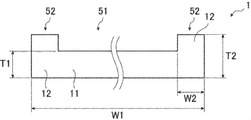
- FIG. 1 It is a top view which shows an example of the glass 1 typically. It is a sectional side view which shows an example of the glass 1 typically. 4 is a side sectional view schematically showing another example of the glass 1.
- FIG. It is side sectional drawing which shows typically an example of the glass 1 comprised by the laminated
- a mobile electronic device represented by a mobile device such as a smartphone or a tablet PC; a display device such as a liquid crystal display (LCD) or a plasma display (PDP) is representative.
- a display device such as a liquid crystal display (LCD) or a plasma display (PDP)
- LCD liquid crystal display
- PDP plasma display
- Stationary electronic equipment and the like.
- the glass such as a glass substrate and a cover glass plate used in the electronic device described above (hereinafter, plate-like glass such as the glass substrate and the cover glass plate is simply referred to as glass in this specification), the mobile type. Regardless of the stationary type, there is a high demand for weight reduction and space saving, and there is a tendency to reduce the plate thickness.
- the edge of glass is susceptible to impacts and is likely to become a starting point of cracking, so there is a high demand for enhancing the edge strength. That is, there is a demand for weight reduction and edge strength enhancement for glass for electronic devices used in electronic devices.
- the glass for electronic devices of the present invention has a relative thickness in the central region of the glass. Because it is light and thin, and the peripheral area is a thick part with a relatively thick plate, weight reduction and enhanced edge strength are achieved. It can be suitably used for the electronic device described above.
- the glass plate for portable devices of the present invention and various other types of glass for electronic devices (hereinafter also referred to simply as “glass”) will be described in more detail with reference to FIGS.
- the present invention is not limited to this.
- FIG. 1 is a plan view schematically showing an example of the glass 1
- FIG. 2 is a side sectional view thereof.
- the region of the glass 1 is roughly divided into a central region 51 and a peripheral region 52 that is an outermost peripheral region surrounding the central region 51.
- the central region 51 mainly constitutes a region through which video / image is transmitted, but other regions may be constructed, and the peripheral region 52 is composed of video / image. You may comprise the area
- the central region 51 is configured by the thin portion 11, and the peripheral region 52 is configured by the thick portion 12 that is thicker than the thin portion 11.
- region 51 is comprised only by the thin part 11
- region 52 may be partially comprised by the thin part 11, and may be comprised by the thick part 12 entirely.
- the thick portion 12 may be provided intermittently in a part of the peripheral region 52 or may be provided in the entire circumference of the glass 1 (that is, the entire peripheral region 52).
- the thick portion 12 that is relatively thicker than the thin portion 11 is disposed at the edge, and therefore, for example, the entire region including the peripheral region 52 is configured by the thin portion 11. Compared to the case, higher energy is required when breaking the edge. That is, the edge strength is excellent. Moreover, in the glass 1, since the thin part 11 relatively thin rather than the thick part 12 comprises the center area
- W1 is used from the viewpoint of being used in a portable device that can be carried. It is preferably 300 mm or less, and more preferably 250 mm or less. On the other hand, for the reason that a thick part having a sufficient thickness can be formed, the width W1 of the thick part is preferably 15 mm or more, and more preferably 20 mm or more.
- W1 is preferably 2500 mm or less, and more preferably 2000 mm or less.
- T1 when the thickness of the thin portion 11 (distance in the vertical direction in FIG. 2) is “T1”, when the glass 1 is used in a portable device, T1 is 1.1 mm from the viewpoint of weight reduction. The following is preferable, and 0.9 mm or less is more preferable. On the other hand, T1 is preferably 0.2 mm or more and more preferably 0.4 mm or more because it has the minimum necessary strength.
- T1 is preferably 1.1 mm or less, and more preferably 0.9 mm or less.
- the lower limit of the width (W2) of the thick portion 12 is represented by (T1) ⁇ (X), and X is preferably 1.5 or more because the edge strength is improved to a significant difference. Two or more are more preferable.
- the upper limit of W2 is represented by (W1 / 2) ⁇ (Y), and Y is preferably 0.2 or less, and more preferably 0.1 or less.
- the thickness (T2) of the thick portion 12 is represented by (T1) ⁇ (Z), and Z is preferably 1.5 or more because the edge strength is improved to a significant degree. Two or more are more preferable.
- X, Y, and Z described above are ratio indicators that are adopted as preferable ranges for designing the dimensions of the glass plate 1 (that is, the dimensions of W2 and T2).
- Z is preferably 65 or less, more preferably 30 or less, because the strength against bending stress is increased.
- the thick part 12 showed the aspect protruded only to the upper surface side (upper side in FIG. 2) of the glass 1 with respect to the thin part 11, it is not limited to this, Next, as will be described with reference to FIG. 3, the thick portion 12 may also protrude to the lower surface side of the glass 1.
- FIG. 3 is a side sectional view schematically showing another example of the glass 1.
- the thick portion 12 protrudes not only on the upper surface side (upper side in FIG. 3) of the glass 1 but also on the lower surface side (lower side in FIG. 3). ing.
- the thickness (T2) of the thick portion 12 is a thickness including portions protruding to the upper surface side and the lower surface side of the glass 1.
- the method for producing glass 1 is not particularly limited, and examples thereof include a method for obtaining glass 1 by polishing a glass plate having a thickness equal to or greater than the thickness (T2) of thick portion 12.
- a conventionally known method can be used, and examples thereof include a method of mechanically polishing the surface of the glass plate, a method of chemically polishing the surface of the glass plate, and the like.
- the manufacturing method of the glass 1 is not limited to polishing.
- FIG. 4 is a side sectional view schematically showing an example of the glass 1 constituted by a plurality of laminated glass plates.
- a second glass plate 32 different from the first glass plate 31 is laminated on the peripheral region 52 of the first glass plate 31.
- the first glass plate 31 constitutes the thin part 11 and a part of the thick part 12, and the second glass plate 32 constitutes the remaining part of the thick part 12.
- the 1st glass plate 31 and / or the 2nd glass plate 32 may be further comprised by the laminated
- the method for laminating is not particularly limited, and a conventionally known method can be used.
- a method of bonding the first glass plate 31 and the second glass plate 32 to each other by bonding A method of heating the plate 31 and the second glass plate 32 to a temperature equal to or higher than the softening point of the two and fusing them together.
- the glass composition of the glass 1 described with reference to FIGS. 1 to 4 is not particularly limited. Moreover, when the glass 1 is comprised with several glass plates (refer FIG. 4), the glass composition of several glass plates may be the same, or may mutually differ. However, the glass 1 may be subjected to a chemical strengthening treatment as described below with reference to FIG. 5, and in that case, as the glass 1, it is necessary to select a glass containing an alkali component, Alkali aluminosilicate glass is preferred.
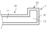
- FIG. 5 is a side sectional view schematically showing an example of the glass 1 subjected to the chemical strengthening treatment.
- a chemical strengthening layer 41 that has been subjected to a chemical strengthening process, which will be described later, and has generated a compressive stress (hereinafter also referred to as “chemically strengthened compressive stress”) is formed.
- the depth of the chemical strengthening layer 41 is not particularly limited, and is preferably 15 to 50 ⁇ m, for example. Further, the chemical strengthening compressive stress of the chemical strengthening layer 41 is not particularly limited, and is preferably, for example, 600 to 2000 MPa.
- the chemical strengthening treatment generally includes an alkali component (for example, an alkali metal ion such as Li ion or Na ion, hereinafter also referred to as “small-diameter alkali component”) present in the glass plate, and an alkali having a larger ion radius.
- an alkali component for example, an alkali metal ion such as Li ion or Na ion, hereinafter also referred to as “small-diameter alkali component” present in the glass plate, and an alkali having a larger ion radius.
- a component for example, an alkali metal ion such as K ion, hereinafter also referred to as “large-diameter alkali component
- the high expansion layer 2 (or the high expansion layer 2)
- a large-diameter alkali component (large-diameter alkali ion) is introduced on the surface of the low expansion layer 3) by ion exchange with a small-diameter alkali component (small-diameter alkali ion), whereby a compressive stress layer is formed on the surface layer.
- the concentration of the large-diameter alkaline component in the chemically strengthened layer 41 is higher than that in the portion excluding the chemically strengthened layer 41. That is, the chemical strengthening layer 41 and the portion excluding the chemical strengthening layer 41 can be clearly distinguished by the difference in the concentration of the large-diameter alkaline component.
- the chemical strengthening treatment include a method in which the glass 1 is immersed in a molten salt of potassium nitrate (KNO 3 ) for 0.25 to 5 hours.
- the chemical strengthening treatment may include a preheat treatment for preheating using a heater or the like as a pretreatment for immersion.
- Examples of the temperature of the chemical strengthening treatment (including preheat treatment) include 550 ° C. or lower.
- the glass for electronic devices of the present invention is suitably used as a cover glass or a glass substrate mounted on a portable device or a display device because it is lighter and has enhanced edge strength.
- Glass A Composition (oxide conversion display) SiO 2: 64.3 mol%, Al 2 O 3: 6 mol%, MgO: 11 mol%, CaO: 0.1 mol%, SrO: 0.06 mol%, BaO: 0.04 mol%, Na 2 O: 12 mol%, K 2 O: 4 mol%, ZrO 2: 2.5 mol%.
- Thermal expansion coefficient 91 ⁇ 10 ⁇ 7 / K Glass transition temperature: 620 ° C
- Softening point 842 ° C -Refractive index: 1.52 ⁇
- Young's modulus 78GPa -Poisson's ratio: 0.22
- a plate-like glass 1 having a cross-sectional view shown in FIG. 2 was produced.
- the total width (W1) of the glass 1, the width (W2) of the thick portion 12, the thickness (T1) of the thin portion 11, and the thickness (T2) of the thick portion 12 are shown in Table 1 below.
- the surface of the glass A having a total width and thickness larger than W1 and T2, respectively, is polished using cerium oxide, and the end face is formed using # 600 diamond abrasive grains.
- glass 1 having a cross-sectional view shown in FIG. 2 was produced by grinding the central region 51 using diamond abrasive grains having a grain size of # 600 to form a counterbore in a square shape.
- the glass for various electronic devices containing the glass plate for portable devices in which weight reduction and reinforcement
Landscapes
- Chemical & Material Sciences (AREA)
- Life Sciences & Earth Sciences (AREA)
- Engineering & Computer Science (AREA)
- Chemical Kinetics & Catalysis (AREA)
- General Chemical & Material Sciences (AREA)
- Geochemistry & Mineralogy (AREA)
- Materials Engineering (AREA)
- Organic Chemistry (AREA)
- Surface Treatment Of Glass (AREA)
- Devices For Indicating Variable Information By Combining Individual Elements (AREA)
- Liquid Crystal (AREA)
Abstract
軽量化及びエッジ強度の強化が実現された電子機器用ガラス及び携帯機器保護用ガラスを提供する。 電子機器用ガラス又は携帯機器保護用ガラスであって、上記ガラスの中央領域(51)を構成する薄肉部(11)と、上記中央領域(51)を囲う周縁領域(52)を構成し、上記薄肉部(11)よりも厚い厚肉部(12)と、を備える電子機器用ガラス又は携帯機器保護用ガラス。
Description
本発明は、電子機器用ガラスおよび携帯機器用ガラスに関する。
近年、モバイル型の電子機器として、スマートフォンやタブレットPC等の携帯機器が急速に普及しており、これら携帯機器に搭載されるカバーガラスの開発が進んでいる(例えば、特許文献1)。
また、家庭用テレビなどの据置き型の電子機器として、液晶ディスプレイ(LCD)やプラズマディスプレイ(PDP)などのディスプレイ装置の大画面化がさらに進行しており、ディスプレイ装置に用いられるカバーガラスやガラス基板についても、大型化が進んでいる。
また、家庭用テレビなどの据置き型の電子機器として、液晶ディスプレイ(LCD)やプラズマディスプレイ(PDP)などのディスプレイ装置の大画面化がさらに進行しており、ディスプレイ装置に用いられるカバーガラスやガラス基板についても、大型化が進んでいる。
携帯機器は、人に常時携帯されて使用されることから、軽量化の要請が高い。そのため、携帯機器に搭載されるカバーガラスは、極僅かな軽量化をも実現するため、板厚が薄くなる傾向にある。
また、ディスプレイ装置においても、用いられるガラスの板厚をなるべく薄くし、装置全体の軽量化や省スペース化を実現しようとする試みがなされている。
また、ディスプレイ装置においても、用いられるガラスの板厚をなるべく薄くし、装置全体の軽量化や省スペース化を実現しようとする試みがなされている。
しかし、ガラスの板厚を薄くすることに伴って、ガラス破壊に必要なエネルギーが低下し、ガラス強度が低下する。とりわけ、ガラスのエッジは、その鋭利な形状から強い衝撃を受けやすく、割れ起点になりやすい。例えば、携帯機器は、携帯使用されるがゆえに、様々な向きからの衝撃を受けやすく、エッジ強度の強化に対する要請も高い。
本発明は、以上の点を鑑みてなされたものであり、軽量化およびエッジ強度の強化が実現された電子機器用ガラスおよび携帯機器用ガラスを提供することを目的とする。
本発明者らが、上記目的を達成するために鋭意検討を行なった結果、ガラスの中央領域を板厚が相対的に薄い薄肉部としつつ、周縁領域を相対的に板厚が厚い厚肉部とすることで、軽量化とエッジ強度の強化とが実現できることを見出し、本発明を完成させた。
すなわち、本発明は、以下の(1)~(8)を提供する。
すなわち、本発明は、以下の(1)~(8)を提供する。
(1)電子機器用ガラスであって、上記ガラスの中央領域を構成する薄肉部と、上記中央領域を囲う周縁領域を構成し、上記薄肉部よりも厚い厚肉部と、を備える電子機器用ガラス。
(2)上記厚肉部が、複数枚のガラス板が積層されて構成されている、上記(1)に記載の電子機器用ガラス。
(3)上記複数枚のガラス板が、それぞれ異なるガラス組成を有する、上記(1)または(2)に記載の電子機器用ガラス。
(4)化学強化処理によって圧縮応力を発生させた化学強化層を表面に有する、上記(1)~(3)のいずれかに記載の電子機器用ガラス。
(5)携帯機器に搭載されるカバーガラスに用いられる携帯機器保護用ガラスであって、
前記ガラスの中央領域を構成する薄肉部と、前記中央領域を囲う周縁領域を構成し、前記薄肉部よりも厚い厚肉部と、を備える携帯機器保護用ガラス。
(6)上記厚肉部が、複数枚のガラス板が積層されて構成されている、上記(5)に記載の携帯機器保護用ガラス。
(7)上記複数枚のガラス板が、それぞれ異なるガラス組成を有する、上記(5)または(6)に記載の携帯機器保護用ガラス。
(8)化学強化処理によって圧縮応力を発生させた化学強化層を表面に有する、上記(5)~(7)のいずれかに記載の携帯機器保護用ガラス。
(5)携帯機器に搭載されるカバーガラスに用いられる携帯機器保護用ガラスであって、
前記ガラスの中央領域を構成する薄肉部と、前記中央領域を囲う周縁領域を構成し、前記薄肉部よりも厚い厚肉部と、を備える携帯機器保護用ガラス。
(6)上記厚肉部が、複数枚のガラス板が積層されて構成されている、上記(5)に記載の携帯機器保護用ガラス。
(7)上記複数枚のガラス板が、それぞれ異なるガラス組成を有する、上記(5)または(6)に記載の携帯機器保護用ガラス。
(8)化学強化処理によって圧縮応力を発生させた化学強化層を表面に有する、上記(5)~(7)のいずれかに記載の携帯機器保護用ガラス。
本発明によれば、軽量化およびエッジ強度の強化が実現された携帯機器用ガラス板、その他各種の電子機器用ガラスを提供することができる。
まず、本発明でいう「電子機器」としては、例えば、スマートフォンやタブレットPCなどの携帯機器に代表されるモバイル型の電子機器;液晶ディスプレイ(LCD)やプラズマディスプレイ(PDP)などのディスプレイ装置に代表される据置き型の電子機器;等が挙げられる。
上述した電子機器に使用されるガラス基板、カバーガラス板等のガラス(以下、本明細書において、これらガラス基板、カバーガラス板等の板状のガラスを単にガラスと称する。)においては、モバイル型、据置き型を問わず、軽量化や省スペース化の要請が高く、板厚を薄くする傾向にあるが、そうすると、ガラス強度も低下する。とりわけ、ガラスのエッジは、衝撃を受けやすく、割れ起点になりやすいため、エッジ強度の強化に対する要請が高い。
すなわち、電子機器に使用される電子機器用ガラスに対しては、軽量化とエッジ強度の強化とが要請されているが、本発明の電子機器用ガラスは、ガラスの中央領域を板厚が相対的に薄い薄肉部とし、周縁領域を相対的に板厚が厚い厚肉部とすることで、軽量化とエッジ強度の強化とが実現されているため、モバイル型、据置き型を問わず、上述した電子機器に好適に用いることができる。
上述した電子機器に使用されるガラス基板、カバーガラス板等のガラス(以下、本明細書において、これらガラス基板、カバーガラス板等の板状のガラスを単にガラスと称する。)においては、モバイル型、据置き型を問わず、軽量化や省スペース化の要請が高く、板厚を薄くする傾向にあるが、そうすると、ガラス強度も低下する。とりわけ、ガラスのエッジは、衝撃を受けやすく、割れ起点になりやすいため、エッジ強度の強化に対する要請が高い。
すなわち、電子機器に使用される電子機器用ガラスに対しては、軽量化とエッジ強度の強化とが要請されているが、本発明の電子機器用ガラスは、ガラスの中央領域を板厚が相対的に薄い薄肉部とし、周縁領域を相対的に板厚が厚い厚肉部とすることで、軽量化とエッジ強度の強化とが実現されているため、モバイル型、据置き型を問わず、上述した電子機器に好適に用いることができる。
以下、このような本発明の携帯機器用ガラス板、その他各種の電子機器用ガラス(以下、これらを含め、単に「ガラス」ともいう)について、図1~図5に基いてより詳細に説明するが、本発明はこれに限定されるものではない。
図1は、ガラス1の一例を模式的に示す平面図であり、図2は、その側断面図である。
図1に示すように、ガラス1の領域は、概略的には、中央領域51と、中央領域51を囲う最外周の領域である周縁領域52とに区分される。
ガラス1が例えばカバーガラスとして用いられる場合、中央領域51は、主として、映像・画像を透過させる領域を構成するが、それ以外の領域を構成してもよく、また、周縁領域52が映像・画像を透過させる領域を構成してもよい。
ガラス1が例えばカバーガラスとして用いられる場合、中央領域51は、主として、映像・画像を透過させる領域を構成するが、それ以外の領域を構成してもよく、また、周縁領域52が映像・画像を透過させる領域を構成してもよい。
図2に示すように、中央領域51は、薄肉部11によって構成され、周縁領域52は、薄肉部11よりも板厚が厚い厚肉部12によって構成される。
なお、中央領域51は、薄肉部11のみによって構成されるが、周縁領域52は、一部が薄肉部11によって構成されていてもよく、また、全部が厚肉部12によって構成されていてもよい。つまり、厚肉部12は、周縁領域52の一部に間欠的に設けられていてもよいし、ガラス1の全周(すなわち、周縁領域52の全部)に設けられていてもよい。
なお、中央領域51は、薄肉部11のみによって構成されるが、周縁領域52は、一部が薄肉部11によって構成されていてもよく、また、全部が厚肉部12によって構成されていてもよい。つまり、厚肉部12は、周縁領域52の一部に間欠的に設けられていてもよいし、ガラス1の全周(すなわち、周縁領域52の全部)に設けられていてもよい。
図2に示すように、ガラス1においては、薄肉部11よりも相対的に厚い厚肉部12がエッジに配置されるため、例えば、周縁領域52を含む全領域が薄肉部11によって構成された場合と比較して、エッジを破壊する際により高いエネルギーを必要とする。すなわち、エッジ強度に優れる。
また、ガラス1においては、厚肉部12よりも相対的に薄い薄肉部11が、全領域の大半を占める中央領域51を構成することから、全領域が厚肉部12によって構成された場合と比較して、軽量化されている。
こうして、ガラス1においては、軽量化とエッジ強度の強化とが実現されている。
また、ガラス1においては、厚肉部12よりも相対的に薄い薄肉部11が、全領域の大半を占める中央領域51を構成することから、全領域が厚肉部12によって構成された場合と比較して、軽量化されている。
こうして、ガラス1においては、軽量化とエッジ強度の強化とが実現されている。
ガラス1の全幅(図2中、左右方向の距離)を「W1」とした場合、ガラス1が携帯機器に使用されるときは、持ち運び可能な携帯機器に使用されるという観点から、W1は、300mm以下であるのが好ましく、250mm以下であるのがより好ましい。
一方、十分な厚みを有する厚肉部を形成可能という理由から、厚肉部の幅W1は、15mm以上であるのが好ましく、20mm以上であるのがより好ましい。
一方、十分な厚みを有する厚肉部を形成可能という理由から、厚肉部の幅W1は、15mm以上であるのが好ましく、20mm以上であるのがより好ましい。
なお、ガラス1がLCDやPDP等のディスプレイ装置に使用される場合には、W1は、2500mm以下であるのが好ましく、2000mm以下であるのがより好ましい。
また、薄肉部11の厚さ(図2中、上下方向の距離)を「T1」とした場合、ガラス1が携帯機器に使用されるときは、軽量化の観点から、T1は、1.1mm以下が好ましく、0.9mm以下がより好ましい。
一方、最低限必要な強度を有するという理由から、T1は、0.2mm以上が好ましく、0.4mm以上がより好ましい。
一方、最低限必要な強度を有するという理由から、T1は、0.2mm以上が好ましく、0.4mm以上がより好ましい。
なお、ガラス1がLCDやPDP等のディスプレイ装置に使用される場合には、T1は、1.1mm以下であるのが好ましく、0.9mm以下であるのがより好ましい。
厚肉部12の幅(図2中、左右方向の距離)を「W2」とし、厚肉部12の厚さ(図2中、上下方向の距離)を「T2」とした場合、これらは、上述した「W1」や「T1」に対する比率によって規定することができる。
すなわち、厚肉部12の幅(W2)の下限は、(T1)×(X)によって表され、エッジ強度が有意差を持つ程度に向上するという理由から、Xは、1.5以上が好ましく、2以上がより好ましい。
一方、重量の増加を抑制できるという理由から、W2の上限は、(W1/2)×(Y)によって表され、Yは、0.2以下が好ましく、0.1以下がより好ましい。
一方、重量の増加を抑制できるという理由から、W2の上限は、(W1/2)×(Y)によって表され、Yは、0.2以下が好ましく、0.1以下がより好ましい。
また、厚肉部12の厚さ(T2)は、(T1)×(Z)によって表され、エッジ強度が有意差を持つ程度に向上するという理由から、Zは、1.5以上が好ましく、2以上がより好ましい。
なお、上記したX、Y、Zは、ガラス板1の寸法(すなわち、W2およびT2の寸法)を設計するのに当たり好ましい範囲として採用される割合の指標である。
一方、厚肉部12に力が加わった際、厚肉部12と薄肉部11との境界を支点とした曲げ応力が発生する。厚肉部12の厚さ(T2)が薄肉部11の厚さ(T1)に対して大きくなると、同じ力が加わった際に発生する曲げ応力も大きくなる。曲げ応力に対する強度が高くなるという理由から、Zは、65以下が好ましく、30以下がより好ましい。
なお、上記したX、Y、Zは、ガラス板1の寸法(すなわち、W2およびT2の寸法)を設計するのに当たり好ましい範囲として採用される割合の指標である。
一方、厚肉部12に力が加わった際、厚肉部12と薄肉部11との境界を支点とした曲げ応力が発生する。厚肉部12の厚さ(T2)が薄肉部11の厚さ(T1)に対して大きくなると、同じ力が加わった際に発生する曲げ応力も大きくなる。曲げ応力に対する強度が高くなるという理由から、Zは、65以下が好ましく、30以下がより好ましい。
なお、図2においては、厚肉部12が、薄肉部11に対して、ガラス1の上面側(図2中上側)にのみ突出した態様を示したが、これに限定されることはなく、次に図3に基いて説明するように、厚肉部12が、ガラス1の下面側にも突出した態様であってもよい。
図3は、ガラス1の別の一例を模式的に示す側断面図である。図3に示すガラス1においては、厚肉部12が、薄肉部11に対して、ガラス1の上面側(図3中上側)にのみならず、下面側(図3中下側)にも突出している。このとき、厚肉部12の厚さ(T2)は、ガラス1の上面側および下面側に突出した部位を含む厚さである。
ガラス1の製造方法は特に限定されず、例えば、厚肉部12の厚さ(T2)以上の板厚を有する1枚のガラス板を研磨して、ガラス1を得る方法が挙げられる。研磨の方法としては、従来公知の方法を用いることができ、例えば、機械的にガラス板の表面を研磨する方法、化学的にガラス板の表面を研磨する方法などが挙げられる。
また、ガラス1の製造方法としては、研磨に限られることはなく、例えば、次に図4に基いて説明するように、複数枚のガラス板を積層して、ガラス1を得る方法が挙げられる。
図4は、積層された複数枚のガラス板によって構成されたガラス1の一例を模式的に示す側断面図である。図4に示すガラス1においては、第1のガラス板31の周縁領域52に、第1のガラス板31とは別の第2のガラス板32が積層されている。第1のガラス板31が、薄肉部11と厚肉部12の一部とを構成し、第2のガラス板32が、厚肉部12の残りの一部を構成している。
なお、第1のガラス板31および/または第2のガラス板32が、さらに、積層された複数枚のガラス板によって構成されていてもよい。
なお、第1のガラス板31および/または第2のガラス板32が、さらに、積層された複数枚のガラス板によって構成されていてもよい。
上記積層の方法としては、特に限定されず、従来公知の方法を用いることができ、例えば、第1のガラス板31と第2のガラス板32とを接着によって互いに接合する方法;第1のガラス板31と第2のガラス板32とを、両者の軟化点以上の温度に加熱して、互いに融着させる方法;等が挙げられる。
図1~図4に基いて説明したガラス1のガラス組成は特に限定されない。また、ガラス1が複数枚のガラス板によって構成されている場合(図4参照)、複数枚のガラス板のガラス組成は、同一であっても互いに異なっていてもよい。
もっとも、ガラス1は、次に図5に基いて説明するように、化学強化処理が施されていてもよく、その場合、ガラス1としては、アルカリ成分を含有するガラスを選択する必要があり、アルカリアルミノシリケートガラスであるのが好ましい。
もっとも、ガラス1は、次に図5に基いて説明するように、化学強化処理が施されていてもよく、その場合、ガラス1としては、アルカリ成分を含有するガラスを選択する必要があり、アルカリアルミノシリケートガラスであるのが好ましい。
図5は、化学強化処理が施されたガラス1の一例を模式的に示す側断面図である。図5に示すガラス1の表面には、後述する化学強化処理が施されて、圧縮応力(以下、「化学強化圧縮応力」ともいう)が発生した化学強化層41が形成されている。
化学強化層41の深さは、特に限定されず、例えば、15~50μmであるのが好ましい。また、化学強化層41の化学強化圧縮応力も特に限定されず、例えば、600~2000MPaであるのが好ましい。
化学強化処理は、概略的には、ガラス板に存在するアルカリ成分(例えば、Liイオン、Naイオン等のアルカリ金属イオンであり、以下「小径アルカリ成分」ともいう)を、イオン半径がより大きいアルカリ成分(例えば、Kイオン等のアルカリ金属イオンであり、以下「大径アルカリ成分」ともいう)で置換する、いわゆるイオン交換処理であり、このように、高膨張層2(または、高膨張層2および低膨張層3)の表面に大径アルカリ成分(大径アルカリイオン)が、小径アルカリ成分(小径アルカリイオン)とのイオン交換により導入されることにより表面層に圧縮応力層が形成され、強度が向上する。
そのため、化学強化層41における大径アルカリ成分の濃度は、化学強化層41を除く部位のそれよりも高い。すなわち、大径アルカリ成分の濃度の違いによって、化学強化層41と、化学強化層41を除く部位とを、明確に区別することができる。
そのため、化学強化層41における大径アルカリ成分の濃度は、化学強化層41を除く部位のそれよりも高い。すなわち、大径アルカリ成分の濃度の違いによって、化学強化層41と、化学強化層41を除く部位とを、明確に区別することができる。
化学強化処理の方法としては、具体的には、例えば、ガラス1を硝酸カリウム(KNO3)の溶融塩に0.25~5時間浸漬させる方法が挙げられる。化学強化処理は、浸漬の前処理として、ヒータ等を用いて予熱する予熱処理を含んでいてもよい。化学強化処理(予熱処理を含む)の温度としては、例えば、550℃以下が挙げられる。
なお、図4に説明したような複数枚のガラス板を積層してなるタイプのガラス1であって、例えば、100℃以下の温度で接着により積層する場合、化学強化処理を施すタイミングは、積層の前であっても後であってもよい。すなわち、図4に示すこの形態のガラス1の場合は、第1のガラス板31および/または第2のガラス板32に化学強化処理を施した後に、積層してもよい。
もっとも、加熱融着により積層する場合には、融着時の加熱によって化学強化処理の効果が消失してしまうため、積層後に化学強化処理を施すことを要する。
もっとも、加熱融着により積層する場合には、融着時の加熱によって化学強化処理の効果が消失してしまうため、積層後に化学強化処理を施すことを要する。
以上説明したように、本発明の電子機器用ガラスは、軽量化およびエッジ強度の強化が実現されているから、携帯機器やディスプレイ装置に搭載されるカバーガラス、ガラス基板として好適に用いられる。
以下に、実施例を挙げて本発明を具体的に説明する。ただし、本発明はこれらに限定されるものではない。
<ガラス組成>
下記実施例1、および比較例1、2において使用されたガラスAの詳細は下記のとおりである。
下記実施例1、および比較例1、2において使用されたガラスAの詳細は下記のとおりである。
(ガラスA)
・組成(酸化物換算表示)
SiO2 :64.3モル%、Al2O3 :6モル%、MgO :11モル%、CaO :0.1モル%、SrO :0.06モル%、BaO :0.04モル%、Na2O :12モル%、K2O :4モル%、ZrO2 :2.5モル%。
・熱膨張係数:91×10-7/K
・ガラス転移温度:620℃
・軟化点:842℃
・屈折率:1.52
・ヤング率:78GPa
・ポアソン比:0.22
・組成(酸化物換算表示)
SiO2 :64.3モル%、Al2O3 :6モル%、MgO :11モル%、CaO :0.1モル%、SrO :0.06モル%、BaO :0.04モル%、Na2O :12モル%、K2O :4モル%、ZrO2 :2.5モル%。
・熱膨張係数:91×10-7/K
・ガラス転移温度:620℃
・軟化点:842℃
・屈折率:1.52
・ヤング率:78GPa
・ポアソン比:0.22
<実施例1>
上記ガラスAを用いて、図2に示す断面視を有する板状のガラス1を作製した。このとき、ガラス1の全幅(W1)、厚肉部12の幅(W2)、薄肉部11の厚さ(T1)、および、厚肉部12の厚さ(T2)については、下記第1表に示すようにした。
具体的には、全幅および厚さが、それぞれ、W1およびT2よりも大きいサイズのガラスAの表面を、酸化セリウムを用いて研磨加工し、端面を粒度が#600番のダイヤモンド砥粒を用いて研削加工した後、中央領域51を同じく粒度が#600番のダイヤモンド砥粒を用いて四角状にザグリ部となるよう研削加工することにより、図2に示す断面視を有するガラス1を作製した。
上記ガラスAを用いて、図2に示す断面視を有する板状のガラス1を作製した。このとき、ガラス1の全幅(W1)、厚肉部12の幅(W2)、薄肉部11の厚さ(T1)、および、厚肉部12の厚さ(T2)については、下記第1表に示すようにした。
具体的には、全幅および厚さが、それぞれ、W1およびT2よりも大きいサイズのガラスAの表面を、酸化セリウムを用いて研磨加工し、端面を粒度が#600番のダイヤモンド砥粒を用いて研削加工した後、中央領域51を同じく粒度が#600番のダイヤモンド砥粒を用いて四角状にザグリ部となるよう研削加工することにより、図2に示す断面視を有するガラス1を作製した。
<比較例1、2>
実施例1で用いたものと同サイズの板状のガラスを研磨して電子機器用ガラスを作製したが、実施例1とは異なり、厚肉部12を設けずに、その厚さは一様にした。比較例1および比較例2のガラスは、薄肉部11の厚さ(T1)が異なり、第1表のとおりである。このときの厚さを便宜的に「T1」とし、下記第1表に記載した。また、厚肉部12を設けなかったので、厚肉部12の幅(W2)および厚さ(T2)について、下記第1表には「-」を記載した。
実施例1で用いたものと同サイズの板状のガラスを研磨して電子機器用ガラスを作製したが、実施例1とは異なり、厚肉部12を設けずに、その厚さは一様にした。比較例1および比較例2のガラスは、薄肉部11の厚さ(T1)が異なり、第1表のとおりである。このときの厚さを便宜的に「T1」とし、下記第1表に記載した。また、厚肉部12を設けなかったので、厚肉部12の幅(W2)および厚さ(T2)について、下記第1表には「-」を記載した。
<評価>
(エッジ強度)
垂直方向から10度、荷重子と接触する面側に傾け配置したガラスのエッジに対して、水平横方向から307gの円柱(直径:40mm)を叩きつけ、エッジを破壊した。円柱は振り子状の軌道を描いてガラスに接触し、その初期高さによってガラスに加わる衝撃エネルギーを可変できる。
20枚のガラスに対して同試験を繰り返し行い、破壊された際の衝撃エネルギーの平均値が0.02J以上であった場合には「A」と評価し、0.02J未満であった場合には「B」と評価した。
実用性の観点から、「A」であれば、エッジ強度に優れるものとして評価できる。
(エッジ強度)
垂直方向から10度、荷重子と接触する面側に傾け配置したガラスのエッジに対して、水平横方向から307gの円柱(直径:40mm)を叩きつけ、エッジを破壊した。円柱は振り子状の軌道を描いてガラスに接触し、その初期高さによってガラスに加わる衝撃エネルギーを可変できる。
20枚のガラスに対して同試験を繰り返し行い、破壊された際の衝撃エネルギーの平均値が0.02J以上であった場合には「A」と評価し、0.02J未満であった場合には「B」と評価した。
実用性の観点から、「A」であれば、エッジ強度に優れるものとして評価できる。
(軽量性)
実施例1のガラスの質量を基準「B」とし、実施例1よりも軽かった場合には「A」と評価し、実施例1よりも重かった場合には「C」と評価した。
「A」または「B」であれば、軽量性に優れるものとして評価できる。
実施例1のガラスの質量を基準「B」とし、実施例1よりも軽かった場合には「A」と評価し、実施例1よりも重かった場合には「C」と評価した。
「A」または「B」であれば、軽量性に優れるものとして評価できる。

上記第1表に示す結果から明らかなように、実施例1は、エッジ強度が「A」で、軽量性が「B」であったことから、エッジ強度の強化と軽量化とがいずれも実現できたことが分かった。
これに対して、比較例1は、軽量性は良好であるもののエッジ強度が劣り、比較例2は、エッジ強度が良好であるものの、軽量性に劣ることが分かった。
これに対して、比較例1は、軽量性は良好であるもののエッジ強度が劣り、比較例2は、エッジ強度が良好であるものの、軽量性に劣ることが分かった。
本発明によれば、軽量化およびエッジ強度の強化が実現された携帯機器用ガラス板を含む各種の電子機器用ガラスを提供することができる。
なお、2012年2月29日に出願された日本特許出願2012-042809号、および2012年7月9日に出願された日本特許出願2012-153586号、の明細書、特許請求の範囲、図面および要約書の全内容をここに引用し、本発明の開示として取り入れるものである。
なお、2012年2月29日に出願された日本特許出願2012-042809号、および2012年7月9日に出願された日本特許出願2012-153586号、の明細書、特許請求の範囲、図面および要約書の全内容をここに引用し、本発明の開示として取り入れるものである。
1 ガラス(電子機器用ガラス)
11 薄肉部
12 厚肉部
31 第1のガラス板
32 第2のガラス板
41 化学強化層
51 中央領域
52 周縁領域
T1 薄肉部の厚さ
T2 厚肉部の厚さ
W1 ガラスの全幅
W2 厚肉部の幅
11 薄肉部
12 厚肉部
31 第1のガラス板
32 第2のガラス板
41 化学強化層
51 中央領域
52 周縁領域
T1 薄肉部の厚さ
T2 厚肉部の厚さ
W1 ガラスの全幅
W2 厚肉部の幅
Claims (8)
- 電子機器用ガラスであって、
前記ガラスの中央領域を構成する薄肉部と、
前記中央領域を囲う周縁領域を構成し、前記薄肉部よりも厚い厚肉部と、を備える電子機器用ガラス。 - 前記厚肉部が、複数枚のガラス板が積層されて構成されている、請求項1に記載の電子機器用ガラス。
- 前記複数枚のガラス板が、それぞれ異なるガラス組成を有する、請求項1または2に記載の電子機器用ガラス。
- 化学強化処理によって圧縮応力を発生させた化学強化層を表面に有する、請求項1~3のいずれか1項に記載の電子機器用ガラス。
- 携帯機器に搭載されるカバーガラスに用いられる携帯機器保護用ガラスであって、
前記ガラスの中央領域を構成する薄肉部と、
前記中央領域を囲う周縁領域を構成し、前記薄肉部よりも厚い厚肉部と、を備える携帯機器保護用ガラス。 - 前記厚肉部が、複数枚のガラス板が積層されて構成されている、請求項5に記載の携帯機器保護用ガラス。
- 前記複数枚のガラス板が、それぞれ異なるガラス組成を有する、請求項5または6に記載の携帯機器保護用ガラス。
- 化学強化処理によって圧縮応力を発生させた化学強化層を表面に有する、請求項5~7のいずれか1項に記載の携帯機器保護用ガラス。
Applications Claiming Priority (4)
| Application Number | Priority Date | Filing Date | Title |
|---|---|---|---|
| JP2012-042809 | 2012-02-29 | ||
| JP2012042809 | 2012-02-29 | ||
| JP2012-153586 | 2012-07-09 | ||
| JP2012153586A JP2015099171A (ja) | 2012-02-29 | 2012-07-09 | 電子機器用ガラス |
Publications (1)
| Publication Number | Publication Date |
|---|---|
| WO2013129402A1 true WO2013129402A1 (ja) | 2013-09-06 |
Family
ID=49082599
Family Applications (1)
| Application Number | Title | Priority Date | Filing Date |
|---|---|---|---|
| PCT/JP2013/054969 Ceased WO2013129402A1 (ja) | 2012-02-29 | 2013-02-26 | 電子機器用ガラス及び携帯機器保護用ガラス |
Country Status (3)
| Country | Link |
|---|---|
| JP (1) | JP2015099171A (ja) |
| TW (1) | TW201350319A (ja) |
| WO (1) | WO2013129402A1 (ja) |
Cited By (2)
| Publication number | Priority date | Publication date | Assignee | Title |
|---|---|---|---|---|
| CN111393999A (zh) * | 2020-01-03 | 2020-07-10 | 捷庭有限公司 | 渐进式玻璃保护贴及其制造方法 |
| WO2022065132A1 (ja) * | 2020-09-24 | 2022-03-31 | 日本電気硝子株式会社 | 強化ガラス |
Families Citing this family (3)
| Publication number | Priority date | Publication date | Assignee | Title |
|---|---|---|---|---|
| JP7006534B2 (ja) * | 2018-04-27 | 2022-02-10 | Agc株式会社 | 化学強化ガラス板、携帯情報端末および化学強化ガラス板の製造方法 |
| EP3998242A4 (en) * | 2019-07-10 | 2023-08-09 | Agc Inc. | GLASS SUBSTRATE, COVER GLASS, ASSEMBLY, ASSEMBLY MANUFACTURING METHOD, IN-VEHICLE DISPLAY DEVICE AND MANUFACTURING METHOD FOR AN IN-VEHICLE DISPLAY DEVICE |
| CN114341073B (zh) * | 2019-09-03 | 2024-02-02 | Agc株式会社 | 玻璃基体单元、盖板玻璃组装体以及车载显示装置 |
Citations (6)
| Publication number | Priority date | Publication date | Assignee | Title |
|---|---|---|---|---|
| JP2005195770A (ja) * | 2004-01-06 | 2005-07-21 | Ibm Japan Ltd | 液晶表示装置、液晶セル、透明基板、および液晶セルの製造方法 |
| JP2010271552A (ja) * | 2009-05-22 | 2010-12-02 | Nec Corp | 表示装置及び電子装置 |
| JP2011037685A (ja) * | 2009-08-17 | 2011-02-24 | Nippon Electric Glass Co Ltd | 素子封止体及びその製造方法並びに素子の封止方法 |
| JP2011136895A (ja) * | 2009-12-04 | 2011-07-14 | Nippon Electric Glass Co Ltd | 合わせガラス |
| JP2012022200A (ja) * | 2010-07-15 | 2012-02-02 | Asahi Glass Co Ltd | ディスプレイ装置 |
| JP2012025657A (ja) * | 2011-08-12 | 2012-02-09 | Hoya Corp | 携帯機器用カバーガラスのガラス基材 |
-
2012
- 2012-07-09 JP JP2012153586A patent/JP2015099171A/ja active Pending
-
2013
- 2013-02-26 WO PCT/JP2013/054969 patent/WO2013129402A1/ja not_active Ceased
- 2013-02-27 TW TW102106948A patent/TW201350319A/zh unknown
Patent Citations (6)
| Publication number | Priority date | Publication date | Assignee | Title |
|---|---|---|---|---|
| JP2005195770A (ja) * | 2004-01-06 | 2005-07-21 | Ibm Japan Ltd | 液晶表示装置、液晶セル、透明基板、および液晶セルの製造方法 |
| JP2010271552A (ja) * | 2009-05-22 | 2010-12-02 | Nec Corp | 表示装置及び電子装置 |
| JP2011037685A (ja) * | 2009-08-17 | 2011-02-24 | Nippon Electric Glass Co Ltd | 素子封止体及びその製造方法並びに素子の封止方法 |
| JP2011136895A (ja) * | 2009-12-04 | 2011-07-14 | Nippon Electric Glass Co Ltd | 合わせガラス |
| JP2012022200A (ja) * | 2010-07-15 | 2012-02-02 | Asahi Glass Co Ltd | ディスプレイ装置 |
| JP2012025657A (ja) * | 2011-08-12 | 2012-02-09 | Hoya Corp | 携帯機器用カバーガラスのガラス基材 |
Cited By (4)
| Publication number | Priority date | Publication date | Assignee | Title |
|---|---|---|---|---|
| CN111393999A (zh) * | 2020-01-03 | 2020-07-10 | 捷庭有限公司 | 渐进式玻璃保护贴及其制造方法 |
| WO2022065132A1 (ja) * | 2020-09-24 | 2022-03-31 | 日本電気硝子株式会社 | 強化ガラス |
| JPWO2022065132A1 (ja) * | 2020-09-24 | 2022-03-31 | ||
| JP7755238B2 (ja) | 2020-09-24 | 2025-10-16 | 日本電気硝子株式会社 | 強化ガラス |
Also Published As
| Publication number | Publication date |
|---|---|
| TW201350319A (zh) | 2013-12-16 |
| JP2015099171A (ja) | 2015-05-28 |
Similar Documents
| Publication | Publication Date | Title |
|---|---|---|
| JP5088717B1 (ja) | 強化ガラス基板及びその製造方法 | |
| JP7041612B2 (ja) | 傷つき難い表面を有する積層ガラス物品 | |
| CN103702952B (zh) | 层叠和离子交换强化的玻璃层叠件及其制备方法 | |
| TWI542559B (zh) | 強化玻璃基板及其製造方法與強化用玻璃基板 | |
| EP2819965B1 (en) | Low cte, ion-exchangeable glass compositions and glass articles comprising the same | |
| JP6313391B2 (ja) | ガラス基板、電子機器用カバーガラス、及びガラス基板の製造方法 | |
| JP2015006959A (ja) | ガラス基板、ガラス基板の製造方法、およびカバーガラス | |
| TWI644878B (zh) | 具有玻璃層及玻璃陶瓷層之物品以及製作該物品之方法 | |
| CN103097319A (zh) | 玻璃片 | |
| JP2014001124A (ja) | 化学強化ガラス板、カバーガラスおよびディスプレイ装置 | |
| KR20120026098A (ko) | 기계적 내구성 에지를 갖는 얇은 기판 | |
| CN107056088A (zh) | 化学强化玻璃板、保护玻璃、带触控传感器的化学强化玻璃及显示装置 | |
| WO2013191200A1 (ja) | 強化ガラスの製造方法 | |
| WO2014185383A1 (ja) | 強化ガラスの製造方法及び強化ガラス | |
| TW201536699A (zh) | 強化玻璃的製造方法以及強化玻璃 | |
| WO2013191110A1 (ja) | 非接触給電用支持部材 | |
| WO2013176150A1 (ja) | 化学強化ガラス板、カバーガラス、タッチセンサ付化学強化ガラスおよびディスプレイ装置 | |
| JP2015099171A (ja) | 電子機器用ガラス | |
| TW202039234A (zh) | 抗損傷玻璃疊層物及其製造方法 | |
| WO2013129400A1 (ja) | 積層強化ガラス | |
| JP2014065624A (ja) | 強化ガラス基板の製造方法 | |
| WO2014034445A1 (ja) | 化学強化ガラス板及びその衝撃試験方法 | |
| US20200172428A1 (en) | Thin multilayer laminate |
Legal Events
| Date | Code | Title | Description |
|---|---|---|---|
| 121 | Ep: the epo has been informed by wipo that ep was designated in this application |
Ref document number: 13754808 Country of ref document: EP Kind code of ref document: A1 |
|
| NENP | Non-entry into the national phase |
Ref country code: DE |
|
| 122 | Ep: pct application non-entry in european phase |
Ref document number: 13754808 Country of ref document: EP Kind code of ref document: A1 |
|
| NENP | Non-entry into the national phase |
Ref country code: JP |