WO2013124994A1 - トロリー式トラック - Google Patents
トロリー式トラック Download PDFInfo
- Publication number
- WO2013124994A1 WO2013124994A1 PCT/JP2012/054327 JP2012054327W WO2013124994A1 WO 2013124994 A1 WO2013124994 A1 WO 2013124994A1 JP 2012054327 W JP2012054327 W JP 2012054327W WO 2013124994 A1 WO2013124994 A1 WO 2013124994A1
- Authority
- WO
- WIPO (PCT)
- Prior art keywords
- frame
- trolley
- pantograph
- truck
- type truck
- Prior art date
- Legal status (The legal status is an assumption and is not a legal conclusion. Google has not performed a legal analysis and makes no representation as to the accuracy of the status listed.)
- Ceased
Links
Images




Classifications
-
- B—PERFORMING OPERATIONS; TRANSPORTING
- B60—VEHICLES IN GENERAL
- B60L—PROPULSION OF ELECTRICALLY-PROPELLED VEHICLES; SUPPLYING ELECTRIC POWER FOR AUXILIARY EQUIPMENT OF ELECTRICALLY-PROPELLED VEHICLES; ELECTRODYNAMIC BRAKE SYSTEMS FOR VEHICLES IN GENERAL; MAGNETIC SUSPENSION OR LEVITATION FOR VEHICLES; MONITORING OPERATING VARIABLES OF ELECTRICALLY-PROPELLED VEHICLES; ELECTRIC SAFETY DEVICES FOR ELECTRICALLY-PROPELLED VEHICLES
- B60L5/00—Current collectors for power supply lines of electrically-propelled vehicles
- B60L5/18—Current collectors for power supply lines of electrically-propelled vehicles using bow-type collectors in contact with trolley wire
- B60L5/22—Supporting means for the contact bow
- B60L5/24—Pantographs
-
- B—PERFORMING OPERATIONS; TRANSPORTING
- B60—VEHICLES IN GENERAL
- B60L—PROPULSION OF ELECTRICALLY-PROPELLED VEHICLES; SUPPLYING ELECTRIC POWER FOR AUXILIARY EQUIPMENT OF ELECTRICALLY-PROPELLED VEHICLES; ELECTRODYNAMIC BRAKE SYSTEMS FOR VEHICLES IN GENERAL; MAGNETIC SUSPENSION OR LEVITATION FOR VEHICLES; MONITORING OPERATING VARIABLES OF ELECTRICALLY-PROPELLED VEHICLES; ELECTRIC SAFETY DEVICES FOR ELECTRICALLY-PROPELLED VEHICLES
- B60L3/00—Electric devices on electrically-propelled vehicles for safety purposes; Monitoring operating variables, e.g. speed, deceleration or energy consumption
- B60L3/0023—Detecting, eliminating, remedying or compensating for drive train abnormalities, e.g. failures within the drive train
-
- B—PERFORMING OPERATIONS; TRANSPORTING
- B60—VEHICLES IN GENERAL
- B60L—PROPULSION OF ELECTRICALLY-PROPELLED VEHICLES; SUPPLYING ELECTRIC POWER FOR AUXILIARY EQUIPMENT OF ELECTRICALLY-PROPELLED VEHICLES; ELECTRODYNAMIC BRAKE SYSTEMS FOR VEHICLES IN GENERAL; MAGNETIC SUSPENSION OR LEVITATION FOR VEHICLES; MONITORING OPERATING VARIABLES OF ELECTRICALLY-PROPELLED VEHICLES; ELECTRIC SAFETY DEVICES FOR ELECTRICALLY-PROPELLED VEHICLES
- B60L5/00—Current collectors for power supply lines of electrically-propelled vehicles
- B60L5/18—Current collectors for power supply lines of electrically-propelled vehicles using bow-type collectors in contact with trolley wire
- B60L5/22—Supporting means for the contact bow
- B60L5/28—Devices for lifting and resetting the collector
-
- B—PERFORMING OPERATIONS; TRANSPORTING
- B60—VEHICLES IN GENERAL
- B60L—PROPULSION OF ELECTRICALLY-PROPELLED VEHICLES; SUPPLYING ELECTRIC POWER FOR AUXILIARY EQUIPMENT OF ELECTRICALLY-PROPELLED VEHICLES; ELECTRODYNAMIC BRAKE SYSTEMS FOR VEHICLES IN GENERAL; MAGNETIC SUSPENSION OR LEVITATION FOR VEHICLES; MONITORING OPERATING VARIABLES OF ELECTRICALLY-PROPELLED VEHICLES; ELECTRIC SAFETY DEVICES FOR ELECTRICALLY-PROPELLED VEHICLES
- B60L5/00—Current collectors for power supply lines of electrically-propelled vehicles
- B60L5/36—Current collectors for power supply lines of electrically-propelled vehicles with means for collecting current simultaneously from more than one conductor, e.g. from more than one phase
-
- B—PERFORMING OPERATIONS; TRANSPORTING
- B60—VEHICLES IN GENERAL
- B60L—PROPULSION OF ELECTRICALLY-PROPELLED VEHICLES; SUPPLYING ELECTRIC POWER FOR AUXILIARY EQUIPMENT OF ELECTRICALLY-PROPELLED VEHICLES; ELECTRODYNAMIC BRAKE SYSTEMS FOR VEHICLES IN GENERAL; MAGNETIC SUSPENSION OR LEVITATION FOR VEHICLES; MONITORING OPERATING VARIABLES OF ELECTRICALLY-PROPELLED VEHICLES; ELECTRIC SAFETY DEVICES FOR ELECTRICALLY-PROPELLED VEHICLES
- B60L50/00—Electric propulsion with power supplied within the vehicle
- B60L50/10—Electric propulsion with power supplied within the vehicle using propulsion power supplied by engine-driven generators, e.g. generators driven by combustion engines
- B60L50/13—Electric propulsion with power supplied within the vehicle using propulsion power supplied by engine-driven generators, e.g. generators driven by combustion engines using AC generators and AC motors
-
- B—PERFORMING OPERATIONS; TRANSPORTING
- B60—VEHICLES IN GENERAL
- B60L—PROPULSION OF ELECTRICALLY-PROPELLED VEHICLES; SUPPLYING ELECTRIC POWER FOR AUXILIARY EQUIPMENT OF ELECTRICALLY-PROPELLED VEHICLES; ELECTRODYNAMIC BRAKE SYSTEMS FOR VEHICLES IN GENERAL; MAGNETIC SUSPENSION OR LEVITATION FOR VEHICLES; MONITORING OPERATING VARIABLES OF ELECTRICALLY-PROPELLED VEHICLES; ELECTRIC SAFETY DEVICES FOR ELECTRICALLY-PROPELLED VEHICLES
- B60L9/00—Electric propulsion with power supply external to the vehicle
- B60L9/16—Electric propulsion with power supply external to the vehicle using AC induction motors
- B60L9/18—Electric propulsion with power supply external to the vehicle using AC induction motors fed from DC supply lines
- B60L9/22—Electric propulsion with power supply external to the vehicle using AC induction motors fed from DC supply lines polyphase motors
-
- B—PERFORMING OPERATIONS; TRANSPORTING
- B60—VEHICLES IN GENERAL
- B60L—PROPULSION OF ELECTRICALLY-PROPELLED VEHICLES; SUPPLYING ELECTRIC POWER FOR AUXILIARY EQUIPMENT OF ELECTRICALLY-PROPELLED VEHICLES; ELECTRODYNAMIC BRAKE SYSTEMS FOR VEHICLES IN GENERAL; MAGNETIC SUSPENSION OR LEVITATION FOR VEHICLES; MONITORING OPERATING VARIABLES OF ELECTRICALLY-PROPELLED VEHICLES; ELECTRIC SAFETY DEVICES FOR ELECTRICALLY-PROPELLED VEHICLES
- B60L2200/00—Type of vehicles
- B60L2200/36—Vehicles designed to transport cargo, e.g. trucks
-
- B—PERFORMING OPERATIONS; TRANSPORTING
- B60—VEHICLES IN GENERAL
- B60L—PROPULSION OF ELECTRICALLY-PROPELLED VEHICLES; SUPPLYING ELECTRIC POWER FOR AUXILIARY EQUIPMENT OF ELECTRICALLY-PROPELLED VEHICLES; ELECTRODYNAMIC BRAKE SYSTEMS FOR VEHICLES IN GENERAL; MAGNETIC SUSPENSION OR LEVITATION FOR VEHICLES; MONITORING OPERATING VARIABLES OF ELECTRICALLY-PROPELLED VEHICLES; ELECTRIC SAFETY DEVICES FOR ELECTRICALLY-PROPELLED VEHICLES
- B60L2240/00—Control parameters of input or output; Target parameters
- B60L2240/10—Vehicle control parameters
- B60L2240/12—Speed
-
- B—PERFORMING OPERATIONS; TRANSPORTING
- B60—VEHICLES IN GENERAL
- B60L—PROPULSION OF ELECTRICALLY-PROPELLED VEHICLES; SUPPLYING ELECTRIC POWER FOR AUXILIARY EQUIPMENT OF ELECTRICALLY-PROPELLED VEHICLES; ELECTRODYNAMIC BRAKE SYSTEMS FOR VEHICLES IN GENERAL; MAGNETIC SUSPENSION OR LEVITATION FOR VEHICLES; MONITORING OPERATING VARIABLES OF ELECTRICALLY-PROPELLED VEHICLES; ELECTRIC SAFETY DEVICES FOR ELECTRICALLY-PROPELLED VEHICLES
- B60L2270/00—Problem solutions or means not otherwise provided for
- B60L2270/10—Emission reduction
- B60L2270/14—Emission reduction of noise
- B60L2270/145—Structure borne vibrations
-
- Y—GENERAL TAGGING OF NEW TECHNOLOGICAL DEVELOPMENTS; GENERAL TAGGING OF CROSS-SECTIONAL TECHNOLOGIES SPANNING OVER SEVERAL SECTIONS OF THE IPC; TECHNICAL SUBJECTS COVERED BY FORMER USPC CROSS-REFERENCE ART COLLECTIONS [XRACs] AND DIGESTS
- Y02—TECHNOLOGIES OR APPLICATIONS FOR MITIGATION OR ADAPTATION AGAINST CLIMATE CHANGE
- Y02T—CLIMATE CHANGE MITIGATION TECHNOLOGIES RELATED TO TRANSPORTATION
- Y02T10/00—Road transport of goods or passengers
- Y02T10/60—Other road transportation technologies with climate change mitigation effect
- Y02T10/70—Energy storage systems for electromobility, e.g. batteries
-
- Y—GENERAL TAGGING OF NEW TECHNOLOGICAL DEVELOPMENTS; GENERAL TAGGING OF CROSS-SECTIONAL TECHNOLOGIES SPANNING OVER SEVERAL SECTIONS OF THE IPC; TECHNICAL SUBJECTS COVERED BY FORMER USPC CROSS-REFERENCE ART COLLECTIONS [XRACs] AND DIGESTS
- Y02—TECHNOLOGIES OR APPLICATIONS FOR MITIGATION OR ADAPTATION AGAINST CLIMATE CHANGE
- Y02T—CLIMATE CHANGE MITIGATION TECHNOLOGIES RELATED TO TRANSPORTATION
- Y02T10/00—Road transport of goods or passengers
- Y02T10/60—Other road transportation technologies with climate change mitigation effect
- Y02T10/7072—Electromobility specific charging systems or methods for batteries, ultracapacitors, supercapacitors or double-layer capacitors
Definitions
- the present invention relates to a trolley-type truck used for ore transportation in a large-scale mine, and in particular, a trolley mode that travels with electric power obtained from an overhead line, and a generator that is driven by an engine without obtaining electric power from the overhead line.
- This is suitable for a trolley-type dump truck that travels in combination with a non-trolley mode that travels with electric power obtained by driving.
- Patent Document 1 Japanese Patent Laid-Open No. 63-35102
- Patent Document 1 a dump truck used for ore transportation in a large-scale mine is described.
- a dump truck In a non-trolley mode, a dump truck is driven by a generator driven by an engine, and in a trolley mode, a pair of pantographs mounted on a vehicle is used. It is described that the vehicle travels with external power by collecting power with a double-wire overhead line.
- this patent document describes an invention in which the pantograph is urgently lowered when the pantograph deviates from the overhead line.
- a trolley type truck as described in Patent Document 1 has a trolley mode that travels with electric power obtained from an overhead line where an overhead line (trolley line) for supplying electric power is laid, and a generator is driven by an engine.
- the vehicle travels in combination with the non-trolley mode that travels with the electric power obtained. Since the road surface where the trolley line is laid is usually well leveled and smooth, the truck does not move up and down violently, sway left and right, or vibrate vigorously.
- An object of the present invention is to obtain a trolley-type truck that can prevent a pantograph mounted on a truck that travels using both a trolley mode and a non-trolley mode from being deformed and broken or damaged.
- the present invention includes a pantograph mounted on a truck, and travels in combination with a trolley mode that travels with electric power obtained from an overhead line and a non-trolley mode that travels without obtaining electric power from the overhead line.
- the pantograph has a base frame, a lower frame that is swingably attached to the base frame, an upper frame that is swingably attached to the lower frame, and a rocker at a tip of the upper frame.
- a current collector boat supported movably, and by raising and lowering the current collector boat up and down while maintaining a posture with respect to the underframe by changing an intersection angle between the lower frame and the upper frame
- a pantograph fixing fixing member provided on the front end side of the upper frame
- a key device for firmly pressing and fixing the pantograph fixing fixing member provided on the underframe
- key device A key holder provided on the underframe to receive the fixed member pressed firmly, and when the frame composed of the lower frame and the upper frame is folded, the fixing member is attached to the key holder. It is configured such that it is seated and firmly pressed by the key device and fixed to the frame.
- the key device includes a key portion for pressing the fixing member, a support member for rotatably holding the key portion, and a force for pressing the fixing member firmly by rotating the key portion.
- a configuration including a hydraulic cylinder is preferable.
- the hook receiver includes a V-shaped receiving portion for firmly receiving the fixing member in the front-rear direction, a base portion for fixing the receiving portion to the base frame, and a receiving side of the receiving portion. It is preferable to provide an elastic material provided on the surface.
- the key device may be provided with a key part opening / closing detection means (such as a limit switch) for detecting the key opening / closing state.
- a roll prevention means for preventing a roll of the frame is provided on the frame when the frame constituted by the lower frame and the upper frame is folded.
- a trolley-type truck that includes a pantograph mounted on a truck and that travels in combination with a trolley mode that travels with electric power obtained from an overhead line and a non-trolley mode that travels without obtaining electric power from the overhead line.
- the pantograph includes a frame, a lower frame that is swingably attached to the frame, an upper frame that is swingably attached to the lower frame, and a rocker that is swingable at the tip of the upper frame.
- a current collector boat supported, and configured to raise and lower the current collector boat up and down while maintaining a posture with respect to the underframe by changing an intersection angle between the lower frame and the upper frame.
- the base frame is provided with roll prevention means for preventing the roll of the frame when the frame composed of the lower frame and the upper frame is folded.
- the roll prevention means is a frame guide having a pair of steel plates arranged so as to sandwich both sides of the frame, and a synthetic resin frame protection member is provided inside each of the pair of steel plates.
- the frame protection member protects the frame from collision and sliding even when it collides or slides when the frame is housed in the frame guide. To do.
- FIG. 1 is an overall perspective view of a pantograph mounted on a trolley type truck in Embodiment 1 of the present invention.
- FIG. 3 is a schematic front view of the pantograph shown in FIG. 2 in a state where the pantograph is erected.
- FIG. 3 is a schematic front view of the pantograph shown in FIG. 2 in a state where the pantograph is folded.
- FIG. 3 is an enlarged detail view of a portion of the pantograph key device shown in FIG.
- FIG. 3 is an enlarged detailed view of a portion of the frame guide shown in FIG. 2, (a) is a front view of the frame guide, and (b) is a side view of the frame guide.
- FIG. 1 is a schematic diagram illustrating the overall configuration of a trolley-type truck according to a first embodiment of the present invention.
- a trolley type dump truck used for ore transportation in a large-scale mine will be described as an example.
- the electricity obtained by the generator is controlled by a control device such as an inverter, and then an alternating current (AC) motor (induction motor).
- a control device such as an inverter, and then an alternating current (AC) motor (induction motor).
- AC alternating current
- An AC drive system is employed in which the vehicle is driven to travel.
- IGBT Insulated Gate Bipolar Transistor
- a pantograph 4 is mounted on the top of the dump truck 2. That is, a pantograph mounting base 3 is installed at the front part of the dump truck 2, and a pantograph 4 for collecting power from the overhead line 1 is installed at the upper part of the base 3 (the front upper part of the cab 2a). Yes.
- Reference numeral 5 denotes a current collecting boat at the top of the pantograph, which slides in contact with the overhead wire 1 and collects electricity from the overhead wire 1.
- FIG. 2 is a perspective view showing the entire structure of the pantograph 4 shown in FIG. 1, and the configuration of the pantograph in this embodiment will be described with reference to FIG.
- 6 is a frame of a pantograph attached to the upper part of the pantograph mounting base 3 shown in FIG.
- a swing support shaft 7 is provided on the upper surface of the underframe 6 in the width direction (lateral direction) of the truck (vehicle).
- the swing support shaft 7 is formed of a cylindrical member, and is provided so as to be swingable by being inserted into a support shaft (not shown) fixed to the frame 6.
- a base end portion of the lower frame 8 is fixed to an intermediate portion of the swing support shaft 7 and is configured to be swingable together with the swing support shaft 7.
- the lower frame 8 undulates around the swing support shaft 7.
- a connecting shaft 9 is provided at the distal end (upper end) of the lower frame 8 in parallel with the swing support shaft 7, and a base end portion 11 of the upper frame 10 is swingably connected to the connecting shaft 9. ing.
- the current collecting boat 5 is swingably supported at the front end (upper end) of the upper frame 10 via a boat support 22 or the like.
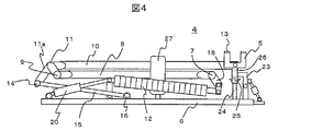
- a spring 12 is provided between the swing support shaft 7 and the frame 6. This spring 12 raises the pantograph from the state in which the pantograph shown in FIG. 4 is folded to the state shown in FIGS. 2 and 3 in the frame constituted by the lower frame 8 and the upper frame 10 together with the hydraulic cylinder 20. The driving force in the direction to be applied is applied.
- the current collecting boat 5 changes the crossing angle between the lower frame 8 and the upper frame 10 according to the change in the distance between the frame 6 and the overhead line 1 of the pantograph, Go up and down with respect to 6. Even in this case, the posture of the current collecting boat 5 is fixed, and the sliding state between the sliding plate 13 disposed on the upper surface of the current collecting boat 5 and the overhead wire 1 is properly maintained. For this reason, a link mechanism is provided at the connecting portion between the distal end portion of the lower frame 8 and the base end portion 11 of the upper frame 10 and the connecting portion between the distal end portion of the upper frame 10 and the current collector boat 5. Thus, regardless of the undulations of the lower frame 8 and the upper frame 10, the posture of the current collecting boat 5 is prevented from changing.
- a counter arm 11a is integrally provided at the base end portion 11 of the upper frame 10 so as to protrude downward, and the counter arm 11a is swung around the connecting shaft 9 together with the upper frame 10. It is composed. Further, an upper balancing shaft 14 is provided at the tip of the balancing arm 11a in parallel with the connecting shaft 9, and the tip (upper end) of the lower balancing rod 15 is swung on the upper balancing shaft 14. It is attached freely. A base end portion (lower end portion) of the balancing rod 15 is swingably attached to the upper surface of the underframe 6 via a lower balancing shaft 16.
- a balancing arm (not shown) is also provided on the lower surface of the current collecting boat 5, and one end of an upper balancing rod 17 is swingably attached to the balancing arm. The other end of the rod 17 is swingably attached around the connecting shaft 9 near the tip of the lower frame 8.
- each spring 12 is provided in the axial direction of the swing support shaft 7, and one end of each spring 12 is fixed to the swing support shaft 7. Each is linked to a link arm 18.
- the other end of each spring 12 is configured such that two springs are connected to the same swinging member 19 and the four springs 12 are expanded and contracted by two hydraulic cylinders 20 provided on the left and right.
- the base end side of the swing member 19 is swingably attached to the underframe 6.
- the proximal end side of the hydraulic cylinder 20 is also attached to the frame 6 so as to be swingable.
- the hydraulic cylinder 20 is expanded and contracted to erect the frame of the pantograph 4 and raise the current collecting boat 5 so as to contact the overhead wire 1, or by folding the frame and the current collecting boat 5 can be lowered and stored. Further, the current collecting boat 5 is pressed against the overhead wire 1 with a constant force through the lower frame 8 and the upper frame 10 by the spring force of the spring 12. At the same time, the current collector boat 5 can be moved up and down by following the relatively large amplitude change of the overhead wire 1 by these configurations.
- FIG. 2 shown in FIG. 2 is a boat receiver.
- the boat support 22 described above is rotatably supported at the top end of the upper frame 10 and the balancing rod 17, and the current collecting boat 5 is attached to the front end portion of the upper frame 10 via the boat support 22. Has been supported.
- 23 is a key device
- 24 is a key holder
- 25 is parallel to the current collecting boat 5 through a bracket 26 on the tip side of the upper frame 10 (below the current collecting boat 5).
- It is a pipe (fixing member) for fixing the attached pantograph.
- the pipe 25 is seated on the key holder 24 when the pantograph is folded (when stored) and is firmly pressed by the key device 23 (see FIG. 4).
- FIGS. 2 to 4 is a frame guide (a means for preventing the frame from rolling), and the frame of the pantograph 4 rolls due to intense vibration or large shaking while driving in the non-trolley mode in which the pantograph 4 is folded. Or to vibrate vigorously in the left-right direction (see FIG. 4).
- FIG. 5 is a front view showing that the key device is in a locked state
- (b) is a view showing that the key device is in an unlocked state
- the key device 23 includes a key portion 23a for pressing the pipe 25 provided in the frame of the pantograph 4, a support member 23b for rotatably mounting the key portion 23a, and a key for rotating the key portion 23a.
- the hydraulic cylinder 23c is used.
- Reference numeral 23d denotes a bracket fixedly attached to the side surface of the pantograph frame 6 and rotatably attached to the base end side of the hydraulic cylinder 23c.
- Reference numeral 23e denotes a limit switch (key part opening / closing detection means) for detecting the open / closed state of the key part 23a, and the base end side of the limit switch 23e is rotatable to a support base 23f fixed to the support member 23b. It is attached.
- the hook receiver 24 is for seating the pipe (fixing member) 25 attached to the upper part of the frame of the pantograph 4 (the front end side of the upper frame 10) as shown in FIGS. 5 (a) and 5 (b).
- the receiving portion 24a has a V-shape so that the pipe 25 can be strongly received in the vertical direction and the front-rear direction of the vehicle (truck). It is fixed by welding or the like to a base portion 24b that is fixed to the upper surface of the base plate 24b. Further, a rubber plate (elastic material) 24c is installed on the receiving side of the pipe of the receiving portion 24a, and the pipe 25 attached to the front end side of the upper frame 10 is attached to the rubber plate 24c by the hook portion 23a.
- the support member 23b of the key portion 23a is also integrally fixed to the base portion 23b of the key receiver 24, and is bolted to the upper surface of the base frame 6 together with the base portion 23b.
- the pipe 25 provided with the key device 23 and the key holder 24 and firmly attached to the upper frame 10 of the pantograph 4 is firmly and constantly pressed by the hydraulic pressure of the hydraulic cylinder 23c. Since the pipe 25 pressed against the key holder 24 is configured to be attached, there is no rattling against severe vibration or shaking, and play (gap) does not increase due to rattling. It is firmly fixed. Therefore, even when the truck 2 travels on a rough road surface in the non-trolley mode, it is possible to reliably prevent the pantograph 4 from being vibrated vigorously, greatly shaken, damaged or deformed.
- the pressing force of the hook portion 23a is performed by the hydraulic cylinder 23c, but it can be pressed down to some extent by using a strong spring or air cylinder instead.
- springs and air are used to press down using elastic deformation, extremely large springs and air cylinders are required to press down strongly so that the pantograph does not shift even if large vibrations or shaking occur. Since it is expensive and large, it is difficult to adopt as a pantograph for a truck.
- the hydraulic cylinder since the hydraulic cylinder uses oil, it does not contract like air even if strong pressure is applied, and a load caused by large vibration or shaking acts on the pipe 25. However, the pressure can be constantly applied so that the pipe 25 is always held stably by the receiving portion 24a without rattling.
- hydraulic cylinders can provide a large force even with a small size, and dump trucks for mines often have a hydraulic power source in the truck itself, and the hydraulic power source can be used, so it can be manufactured very cheaply. It becomes possible.
- FIG. 6 is an enlarged detail view of the frame guide part, (a) is a front view of the frame guide, and (b) is a side view of the frame guide.
- the frame guide (frame roll prevention means) 27 prevents the frame of the pantograph 4 from rolling sideways or greatly vibrating in the left-right direction due to intense vibration or shaking while driving in the non-trolley mode in which the pantograph 4 is folded. It has a function to suppress.
- 27a is a support portion attached to the pantograph frame 6 with bolts
- 27b is a pair of steel plates attached to the left and right upper portions of the support portion 27a by welding
- 27c is the pair of left and right steel plates.
- It is a frame protection member attached to the inside of each of 27b with a screw 27d.
- reference numeral 8 shown by a two-dot chain line is a lower frame of the frame of the pantograph 4, 10 is also an upper frame, and when the frame is folded, the left and right sides of the frame guide 27 are The lower frame 8 and the upper frame 10 are accommodated between the steel plates 27b as shown in the figure.
- Protrusions 8 a and 10 a are attached to portions of the lower frame 8 and the upper frame 10 that are accommodated in the frame guide 27. These protrusions 8a and 10a are for preventing the frame from directly hitting (contacting) the frame guide 27 when the lower frame 8 and the upper frame 10 are housed in the frame guide 27. .
- the frame protection member 27c is composed of a plate-shaped member made of a synthetic resin (for example, polyamide), and the frame assembly (the lower frame 8 and the upper frame 10) is stored in the frame guide or during storage. However, even when sliding with the frame guide, the sliding property is improved to prevent damage, and even when the frame and the frame guide 27 collide, they are protected from the impact.
- a synthetic resin for example, polyamide
- the frame of the pantograph 4 can be used even if the trolley-type dump truck travels in the non-trolley mode and vibrates or shakes. Can be prevented from swaying with respect to the underframe 6 and greatly oscillating in the left-right direction, so that the pantograph frame can be prevented from being deformed or damaged.
- the pipe 25 attached to the tip of the upper frame 10 by the key device 23 and the key receiver 24 can be firmly fixed to the base frame 6, it is possible to reliably prevent the frame assembly from vibrating in the vertical direction, and in the horizontal direction. Vibrating can also be suppressed by the pressing force of the key device.
- the frame guide 27 can hold the vicinity of the substantially central portion of the lower frame 8 and the upper frame 10 so as not to be swayed to the left and right, it is possible to reliably suppress the swaying and vibration especially in the left-right direction.
- the present invention is not necessarily limited to the combination of these devices, and only the key device 23 or the frame guide. It is possible to suppress the deformation and breakage of the pantograph frame even if only 27 is used, and the use of either the key device 23 or the frame guide 27 is within the scope of the present invention.
Landscapes
- Engineering & Computer Science (AREA)
- Power Engineering (AREA)
- Transportation (AREA)
- Mechanical Engineering (AREA)
- Life Sciences & Earth Sciences (AREA)
- Sustainable Development (AREA)
- Sustainable Energy (AREA)
- Current-Collector Devices For Electrically Propelled Vehicles (AREA)
Description
また、前記下枠及び上枠の前記枠組ガイドに収納される部分には、枠組が枠組ガイドに直接接触するのを防止するための突起部を設けることが好ましい。
図1は、本発明のトロリー式トラックの実施例1を説明する全体構成概略図である。この実施例では、大規模鉱山での鉱石運搬などに使用されるトロリー式ダンプトラックを例に挙げ説明する。
図2において、6は図1に示したパンタグラフ搭載用架台3の上部に取り付けられるパンタグラフの台枠である。この台枠6の上面には揺動支持軸7がトラック(車両)の幅方向(横方向)に設けられている。この揺動支持軸7は円筒状の部材で構成され、前記台枠6に固定された支持軸(図示せず)に挿入して揺動自在に設けられている。この揺動支持軸7の中間部に、下枠8の基端部が固設され揺動支持軸7と共に揺動自在に構成されている。
このように構成することにより、前記下枠8及び上枠10の起伏に拘らず、前記集電舟5の姿勢が変化しないようにしている。
なお、この実施例では、前記かぎ部23aの支持部材23bも、前記かぎ受け24の台部23bに一体に固定され、台部23bと共に前記台枠6上面にボルト固定されている。
2:ダンプトラック、
3:パンタグラフ搭載用架台、
4:パンタグラフ、5:集電舟、6:台枠、7:揺動支持軸、
8:下枠、8a:突起部、9:連結軸、10:上枠、10a:突起部、
12:ばね、13:摺り板、
15:下釣合棒、17:上釣合棒、
18:リンク腕、19:揺動部材、
21:舟受け、22:舟支え、
23:かぎ装置、23a:かぎ部、23b:支持部材、23c:油圧シリンダ、
23e:リミットスイッチ(かぎ部開閉検出手段)、
24かぎ受け、24a:受け部、24b:台部、24c:ゴム板(弾性材)、
25:パンタグラフ固定用のパイプ(固定部材)、
27:枠組ガイド(枠組の横揺れ防止手段)、27a:支持部、27b:鋼板、
27c:枠組保護部材、27d:ねじ。
Claims (7)
- トラックに搭載されたパンタグラフを備え、架線から得た電力で走行するトロリーモードと、架線から電力を得ないで走行する非トロリーモードを併用して走行するトロリー式トラックにおいて、
前記パンタグラフは、台枠と、この台枠に揺動自在に取り付けられた下枠と、この下枠に揺動自在に取り付けた上枠と、この上枠の先端部に揺動自在に支持された集電舟とを備え、前記下枠と上枠との交差角度を変化させることで、前記集電舟を前記台枠に対して姿勢を保持しながら上下に昇降するように構成し、
前記上枠の先端側に設けられたパンタグラフ固定用の固定部材と、
前記台枠に設けられ前記パンタグラフ固定用の固定部材を強固に押え付けて固定するためのかぎ装置と、
前記かぎ装置により強固に押え付けられた前記固定部材を受けるために前記台枠に設けられたかぎ受けとを備え、
前記下枠と上枠で構成された枠組が畳まれると、前記固定部材が前記かぎ受けに着座し、前記かぎ装置により強固に押え付けられて台枠に固定される構成とした
ことを特徴とするトロリー式トラック。 - 請求項1に記載のトロリー式トラックにおいて、前記かぎ装置は、前記固定部材を押え込むためのかぎ部と、このかぎ部を回動自在に保持する支持部材と、前記かぎ部を回動させ前記固定部材を強固に押え付けるための油圧シリンダとを備えることを特徴とするトロリー式トラック。
- 請求項2に記載のトロリー式トラックにおいて、前記かぎ受けは、前記固定部材を前後方向に強固に受け止めるためのV字形状の受け部と、この受け部を前記台枠に固定するための台部と、前記受け部の受け側の面に設けられた弾性材とを備えていることを特徴とするトロリー式トラック。
- 請求項2に記載のトロリー式トラックにおいて、前記下枠と上枠で構成された枠組が畳まれた状態のとき、前記枠組の横揺れを防止するための横揺れ防止手段を前記台枠に設けていることを特徴とするトロリー式トラック。
- トラックに搭載されたパンタグラフを備え、架線から得た電力で走行するトロリーモードと、架線から電力を得ないで走行する非トロリーモードを併用して走行するトロリー式トラックにおいて、
前記パンタグラフは、台枠と、この台枠に揺動自在に取り付けられた下枠と、この下枠に揺動自在に取り付けた上枠と、この上枠の先端部に揺動自在に支持された集電舟とを備え、前記下枠と上枠との交差角度を変化させることで、前記集電舟を前記台枠に対して姿勢を保持しながら上下に昇降するように構成し、
前記下枠と上枠で構成された枠組が畳まれた状態のとき、前記枠組の横揺れを防止するための横揺れ防止手段を前記台枠に設けていることを特徴とするトロリー式トラック。 - 請求項4または5に記載のトロリー式トラックにおいて、前記横揺れ防止手段は、前記枠組の両側を挟み込むように配置された一対の鋼板を有する枠組ガイドであって、前記一対の鋼板のそれぞれの内側には合成樹脂製の枠組保護部材が設けられ、この枠組保護部材は、前記枠組が前記枠組ガイドに収納される際に、該枠組ガイドに衝突したり摺動しても、その衝突や摺動から前記枠組を保護するものであることを特徴とするトロリー式トラック。
- 請求項6に記載のトロリー式トラックにおいて、前記下枠及び上枠の前記枠組ガイドに収納される部分には、枠組が枠組ガイドに直接接触するのを防止するための突起部が設けられていることを特徴とするトロリー式トラック。
Priority Applications (4)
| Application Number | Priority Date | Filing Date | Title |
|---|---|---|---|
| PCT/JP2012/054327 WO2013124994A1 (ja) | 2012-02-22 | 2012-02-22 | トロリー式トラック |
| CN201280070226.8A CN104185567B (zh) | 2012-02-22 | 2012-02-22 | 架线式卡车 |
| US14/379,761 US9393874B2 (en) | 2012-02-22 | 2012-02-22 | Trolley-type truck |
| JP2014500804A JP5844451B2 (ja) | 2012-02-22 | 2012-02-22 | トロリー式トラック |
Applications Claiming Priority (1)
| Application Number | Priority Date | Filing Date | Title |
|---|---|---|---|
| PCT/JP2012/054327 WO2013124994A1 (ja) | 2012-02-22 | 2012-02-22 | トロリー式トラック |
Publications (1)
| Publication Number | Publication Date |
|---|---|
| WO2013124994A1 true WO2013124994A1 (ja) | 2013-08-29 |
Family
ID=49005216
Family Applications (1)
| Application Number | Title | Priority Date | Filing Date |
|---|---|---|---|
| PCT/JP2012/054327 Ceased WO2013124994A1 (ja) | 2012-02-22 | 2012-02-22 | トロリー式トラック |
Country Status (4)
| Country | Link |
|---|---|
| US (1) | US9393874B2 (ja) |
| JP (1) | JP5844451B2 (ja) |
| CN (1) | CN104185567B (ja) |
| WO (1) | WO2013124994A1 (ja) |
Cited By (9)
| Publication number | Priority date | Publication date | Assignee | Title |
|---|---|---|---|---|
| WO2015075773A1 (ja) * | 2013-11-19 | 2015-05-28 | 日立建機株式会社 | トロリー式トラック用パンタグラフ装置 |
| CN104859457A (zh) * | 2014-02-24 | 2015-08-26 | 法维莱运输图尔公司 | 轨道交通工具受电弓 |
| CN105034816A (zh) * | 2015-08-07 | 2015-11-11 | 上海尊阶士工程技术有限公司 | 一种用于集电杆的四连杆机构 |
| WO2019058757A1 (ja) * | 2017-09-19 | 2019-03-28 | 日立建機株式会社 | 電気駆動車両 |
| CN113650502A (zh) * | 2021-08-18 | 2021-11-16 | 北方瑞能(内蒙古)集团有限公司 | 一种混合动力自卸车的自适应稳定接触取电装置 |
| JP2024507128A (ja) * | 2021-02-17 | 2024-02-16 | シュンク トランジット ジステムズ ゲーエムベーハー | 位置決めユニットと接触方法 |
| WO2026003124A1 (de) | 2024-06-25 | 2026-01-02 | Voss Automotive Gmbh | Hohlzylindrisches formteil mit gewinde |
| WO2026002752A1 (de) | 2024-06-25 | 2026-01-02 | Voss Automotive Gmbh | Hohlzylindrisches formteil mit gewinde |
| WO2026002751A1 (de) | 2024-06-25 | 2026-01-02 | Voss Automotive Gmbh | Verfahren zur herstellung eines hohlzylindrischen formteils mit gewinde |
Families Citing this family (11)
| Publication number | Priority date | Publication date | Assignee | Title |
|---|---|---|---|---|
| US9381818B2 (en) * | 2012-09-28 | 2016-07-05 | Siemens Aktiengesellschaft | Non-track-bound vehicle |
| CN105984351A (zh) * | 2015-01-29 | 2016-10-05 | 徐工集团工程机械股份有限公司 | 电传动自卸车动力系统、电传动自卸车以及方法 |
| CN104859456B (zh) * | 2015-06-16 | 2017-08-18 | 南车株洲电力机车有限公司 | 一种变轨迹受流器及电动车辆 |
| CN105291849A (zh) * | 2015-11-02 | 2016-02-03 | 湖南中通电气股份有限公司 | 用于受电弓的电动直驱装置 |
| CN105235530B (zh) * | 2015-11-05 | 2018-06-01 | 苏州凯博易控驱动技术有限公司 | 一种锁杆机构 |
| DE102016205012A1 (de) * | 2016-03-24 | 2017-09-28 | Schunk Bahn- Und Industrietechnik Gmbh | Positioniereinheit und Verfahren zur Kontaktierung |
| CN107054098A (zh) * | 2017-06-06 | 2017-08-18 | 中车株洲电力机车有限公司 | 一种受流器用升降装置 |
| EP3702204A1 (de) * | 2019-02-27 | 2020-09-02 | Furrer + Frey AG | Einfettverfahren |
| EP3828024B1 (en) | 2019-11-28 | 2023-03-29 | Hitachi Energy Switzerland AG | Electrical vehicle comprising an energy transfer device |
| CN113147416B (zh) * | 2021-04-21 | 2024-02-13 | 常州市荣江机电有限公司 | 一种新型电机车 |
| US12528359B2 (en) * | 2022-07-21 | 2026-01-20 | Caterpillar Inc. | Pantograph assembly with force dampeners |
Citations (5)
| Publication number | Priority date | Publication date | Assignee | Title |
|---|---|---|---|---|
| JPH0363001U (ja) * | 1989-10-25 | 1991-06-20 | ||
| JPH09107603A (ja) * | 1995-10-09 | 1997-04-22 | Fuji Electric Co Ltd | パンタグラフ |
| JP2004304895A (ja) * | 2003-03-31 | 2004-10-28 | Railway Technical Res Inst | パンタグラフ |
| JP2007028814A (ja) * | 2005-07-19 | 2007-02-01 | Railway Technical Res Inst | 交流電気車パンタグラフ上昇制御装置、及び交流電気車のパンタグラフ上昇制御方法 |
| WO2011135870A1 (ja) * | 2010-04-28 | 2011-11-03 | 株式会社日立エンジニアリング・アンド・サービス | パンタグラフを有する車両及びそのパンタグラフの操作方法 |
Family Cites Families (16)
| Publication number | Priority date | Publication date | Assignee | Title |
|---|---|---|---|---|
| US1828945A (en) * | 1929-04-23 | 1931-10-27 | Rossman Patents Inc | Trolley system for electric railways |
| JPH0797881B2 (ja) | 1986-07-29 | 1995-10-18 | 東洋電機製造株式会社 | トロリ−アシスト車両用パンタグラフの架線外れ検知装置 |
| US5124510A (en) * | 1990-08-16 | 1992-06-23 | Marvin Garfinkle | Tracking pantograph for railway electrification |
| US5954171A (en) * | 1996-08-05 | 1999-09-21 | Abb Patent Gmbh | Moving contact |
| DE19852639B4 (de) * | 1998-11-14 | 2004-10-07 | Daimlerchrysler Ag | Stromabnehmer |
| FR2818938B1 (fr) * | 2000-12-29 | 2003-02-28 | Faiveley Transport | Dispositif de captage d'un pantographe |
| CN101580026B (zh) * | 2009-06-18 | 2011-04-13 | 上海交通大学 | 双线分列倾摆型公交电车受电弓 |
| US20120212047A1 (en) * | 2009-10-27 | 2012-08-23 | Masataka Sasaki | Electric drive vehicle |
| US20110106349A1 (en) * | 2009-10-30 | 2011-05-05 | Masami Sakita | Vehicle operated on electric highway |
| JP5767852B2 (ja) * | 2011-05-10 | 2015-08-19 | 株式会社小松製作所 | 集電装置付運搬車両 |
| JP5592832B2 (ja) * | 2011-05-17 | 2014-09-17 | 日立建機株式会社 | 電気駆動ダンプトラック |
| DE102011076615A1 (de) * | 2011-05-27 | 2012-11-29 | Siemens Aktiengesellschaft | Nicht schienengebundenes Fahrzeug |
| DE102011076623A1 (de) * | 2011-05-27 | 2012-11-29 | Siemens Ag | Nicht schienengebundenes Fahrzeug |
| JP5585791B2 (ja) * | 2011-09-27 | 2014-09-10 | 日立建機株式会社 | 電気駆動ダンプトラック |
| JP5585790B2 (ja) * | 2011-09-27 | 2014-09-10 | 日立建機株式会社 | 電気駆動ダンプトラック |
| US20130105264A1 (en) * | 2011-10-26 | 2013-05-02 | Caterpillar Inc. | Pantograph assembly |
-
2012
- 2012-02-22 US US14/379,761 patent/US9393874B2/en active Active
- 2012-02-22 WO PCT/JP2012/054327 patent/WO2013124994A1/ja not_active Ceased
- 2012-02-22 CN CN201280070226.8A patent/CN104185567B/zh active Active
- 2012-02-22 JP JP2014500804A patent/JP5844451B2/ja active Active
Patent Citations (5)
| Publication number | Priority date | Publication date | Assignee | Title |
|---|---|---|---|---|
| JPH0363001U (ja) * | 1989-10-25 | 1991-06-20 | ||
| JPH09107603A (ja) * | 1995-10-09 | 1997-04-22 | Fuji Electric Co Ltd | パンタグラフ |
| JP2004304895A (ja) * | 2003-03-31 | 2004-10-28 | Railway Technical Res Inst | パンタグラフ |
| JP2007028814A (ja) * | 2005-07-19 | 2007-02-01 | Railway Technical Res Inst | 交流電気車パンタグラフ上昇制御装置、及び交流電気車のパンタグラフ上昇制御方法 |
| WO2011135870A1 (ja) * | 2010-04-28 | 2011-11-03 | 株式会社日立エンジニアリング・アンド・サービス | パンタグラフを有する車両及びそのパンタグラフの操作方法 |
Cited By (12)
| Publication number | Priority date | Publication date | Assignee | Title |
|---|---|---|---|---|
| WO2015075773A1 (ja) * | 2013-11-19 | 2015-05-28 | 日立建機株式会社 | トロリー式トラック用パンタグラフ装置 |
| CN104859457A (zh) * | 2014-02-24 | 2015-08-26 | 法维莱运输图尔公司 | 轨道交通工具受电弓 |
| CN104859457B (zh) * | 2014-02-24 | 2018-06-05 | 法维莱运输图尔公司 | 轨道交通工具受电弓 |
| CN105034816A (zh) * | 2015-08-07 | 2015-11-11 | 上海尊阶士工程技术有限公司 | 一种用于集电杆的四连杆机构 |
| WO2019058757A1 (ja) * | 2017-09-19 | 2019-03-28 | 日立建機株式会社 | 電気駆動車両 |
| JP2019054679A (ja) * | 2017-09-19 | 2019-04-04 | 日立建機株式会社 | 電気駆動車両 |
| US10894468B2 (en) | 2017-09-19 | 2021-01-19 | Hitachi Construction Machinery Co., Ltd. | Electric drive vehicle |
| JP2024507128A (ja) * | 2021-02-17 | 2024-02-16 | シュンク トランジット ジステムズ ゲーエムベーハー | 位置決めユニットと接触方法 |
| CN113650502A (zh) * | 2021-08-18 | 2021-11-16 | 北方瑞能(内蒙古)集团有限公司 | 一种混合动力自卸车的自适应稳定接触取电装置 |
| WO2026003124A1 (de) | 2024-06-25 | 2026-01-02 | Voss Automotive Gmbh | Hohlzylindrisches formteil mit gewinde |
| WO2026002752A1 (de) | 2024-06-25 | 2026-01-02 | Voss Automotive Gmbh | Hohlzylindrisches formteil mit gewinde |
| WO2026002751A1 (de) | 2024-06-25 | 2026-01-02 | Voss Automotive Gmbh | Verfahren zur herstellung eines hohlzylindrischen formteils mit gewinde |
Also Published As
| Publication number | Publication date |
|---|---|
| US9393874B2 (en) | 2016-07-19 |
| US20150034441A1 (en) | 2015-02-05 |
| JP5844451B2 (ja) | 2016-01-20 |
| JPWO2013124994A1 (ja) | 2015-05-21 |
| CN104185567B (zh) | 2016-09-28 |
| CN104185567A (zh) | 2014-12-03 |
Similar Documents
| Publication | Publication Date | Title |
|---|---|---|
| JP5844451B2 (ja) | トロリー式トラック | |
| JP5932995B2 (ja) | トロリー式トラックのパンタグラフ装置 | |
| US20130105264A1 (en) | Pantograph assembly | |
| JP6695311B2 (ja) | 電気駆動車両 | |
| JP5844452B2 (ja) | トロリー式トラックのパンタグラフ制御装置 | |
| WO2015075773A1 (ja) | トロリー式トラック用パンタグラフ装置 | |
| CN103261015B (zh) | 电动摩托车 | |
| CN107709132A (zh) | 铁道车辆的排障装置 | |
| KR101622261B1 (ko) | 모노레일 차량의 조향구조 | |
| JP2018535631A (ja) | 車両のための充電デバイス | |
| CN105378188B (zh) | 用于建筑机械的架空步道 | |
| TW201803763A (zh) | 電動車輛的驅動裝置 | |
| JP2019167060A (ja) | 車両のバッテリーパック保護構造 | |
| JP2013169965A (ja) | 発電装置を備えた鉄道車両用台車およびその台車を備える鉄道車両 | |
| JP2016049936A (ja) | 除雪装置、車両、及び軌道系交通システム | |
| KR20120016818A (ko) | 모노레일 차량 시스템 | |
| CN204879285U (zh) | 一种发动机悬置软垫装置 | |
| KR101083512B1 (ko) | 철도차량의 대차 연결 장치 | |
| JP6199063B2 (ja) | 台車に装備する多機能異常検知装置 | |
| CN117104294A (zh) | 一种防脱轨装置 | |
| KR101662155B1 (ko) | 모노레일 차량 센터피봇 구조 | |
| KR20130050813A (ko) | 편심 모노레일 시스템 | |
| JP2019017213A (ja) | 電気駆動車両 | |
| JP7561524B2 (ja) | 集電装置取付構造 | |
| KR20110023721A (ko) | 2대차식 대형 사행 승강기 |
Legal Events
| Date | Code | Title | Description |
|---|---|---|---|
| 121 | Ep: the epo has been informed by wipo that ep was designated in this application |
Ref document number: 12869144 Country of ref document: EP Kind code of ref document: A1 |
|
| ENP | Entry into the national phase |
Ref document number: 2014500804 Country of ref document: JP Kind code of ref document: A |
|
| NENP | Non-entry into the national phase |
Ref country code: DE |
|
| WWE | Wipo information: entry into national phase |
Ref document number: 14379761 Country of ref document: US |
|
| 122 | Ep: pct application non-entry in european phase |
Ref document number: 12869144 Country of ref document: EP Kind code of ref document: A1 |