WO2013122097A1 - 電池補強方法 - Google Patents
電池補強方法 Download PDFInfo
- Publication number
- WO2013122097A1 WO2013122097A1 PCT/JP2013/053381 JP2013053381W WO2013122097A1 WO 2013122097 A1 WO2013122097 A1 WO 2013122097A1 JP 2013053381 W JP2013053381 W JP 2013053381W WO 2013122097 A1 WO2013122097 A1 WO 2013122097A1
- Authority
- WO
- WIPO (PCT)
- Prior art keywords
- battery
- battery cell
- reinforcing
- exterior material
- reinforcing portion
- Prior art date
Links
- 238000000034 method Methods 0.000 title claims abstract description 39
- 230000002787 reinforcement Effects 0.000 title claims abstract description 26
- 230000003014 reinforcing effect Effects 0.000 claims abstract description 65
- 238000007789 sealing Methods 0.000 claims abstract description 33
- 239000000463 material Substances 0.000 claims description 35
- 239000011347 resin Substances 0.000 claims description 8
- 229920005989 resin Polymers 0.000 claims description 8
- 230000015572 biosynthetic process Effects 0.000 claims description 2
- 238000007599 discharging Methods 0.000 claims description 2
- 239000002184 metal Substances 0.000 claims 1
- 238000005253 cladding Methods 0.000 abstract 5
- 230000032258 transport Effects 0.000 description 17
- 238000012545 processing Methods 0.000 description 12
- 238000010586 diagram Methods 0.000 description 6
- 230000004927 fusion Effects 0.000 description 5
- 238000010248 power generation Methods 0.000 description 5
- 238000013459 approach Methods 0.000 description 4
- 238000005452 bending Methods 0.000 description 4
- 239000000758 substrate Substances 0.000 description 4
- 239000005022 packaging material Substances 0.000 description 3
- XAGFODPZIPBFFR-UHFFFAOYSA-N aluminium Chemical compound [Al] XAGFODPZIPBFFR-UHFFFAOYSA-N 0.000 description 2
- 229910052782 aluminium Inorganic materials 0.000 description 2
- 239000008151 electrolyte solution Substances 0.000 description 2
- 239000007773 negative electrode material Substances 0.000 description 2
- 239000007774 positive electrode material Substances 0.000 description 2
- 230000009466 transformation Effects 0.000 description 2
- 239000000853 adhesive Substances 0.000 description 1
- 230000001070 adhesive effect Effects 0.000 description 1
- 239000011248 coating agent Substances 0.000 description 1
- 238000000576 coating method Methods 0.000 description 1
- 238000012937 correction Methods 0.000 description 1
- 239000012467 final product Substances 0.000 description 1
- 238000010438 heat treatment Methods 0.000 description 1
- 238000004806 packaging method and process Methods 0.000 description 1
- 230000002265 prevention Effects 0.000 description 1
- 239000000047 product Substances 0.000 description 1
- 238000012546 transfer Methods 0.000 description 1
Images


Classifications
-
- H—ELECTRICITY
- H01—ELECTRIC ELEMENTS
- H01M—PROCESSES OR MEANS, e.g. BATTERIES, FOR THE DIRECT CONVERSION OF CHEMICAL ENERGY INTO ELECTRICAL ENERGY
- H01M50/00—Constructional details or processes of manufacture of the non-active parts of electrochemical cells other than fuel cells, e.g. hybrid cells
- H01M50/10—Primary casings; Jackets or wrappings
- H01M50/116—Primary casings; Jackets or wrappings characterised by the material
- H01M50/121—Organic material
-
- H—ELECTRICITY
- H01—ELECTRIC ELEMENTS
- H01M—PROCESSES OR MEANS, e.g. BATTERIES, FOR THE DIRECT CONVERSION OF CHEMICAL ENERGY INTO ELECTRICAL ENERGY
- H01M50/00—Constructional details or processes of manufacture of the non-active parts of electrochemical cells other than fuel cells, e.g. hybrid cells
- H01M50/10—Primary casings; Jackets or wrappings
- H01M50/102—Primary casings; Jackets or wrappings characterised by their shape or physical structure
- H01M50/105—Pouches or flexible bags
-
- H—ELECTRICITY
- H01—ELECTRIC ELEMENTS
- H01M—PROCESSES OR MEANS, e.g. BATTERIES, FOR THE DIRECT CONVERSION OF CHEMICAL ENERGY INTO ELECTRICAL ENERGY
- H01M50/00—Constructional details or processes of manufacture of the non-active parts of electrochemical cells other than fuel cells, e.g. hybrid cells
- H01M50/10—Primary casings; Jackets or wrappings
- H01M50/116—Primary casings; Jackets or wrappings characterised by the material
- H01M50/117—Inorganic material
- H01M50/119—Metals
-
- H—ELECTRICITY
- H01—ELECTRIC ELEMENTS
- H01M—PROCESSES OR MEANS, e.g. BATTERIES, FOR THE DIRECT CONVERSION OF CHEMICAL ENERGY INTO ELECTRICAL ENERGY
- H01M50/00—Constructional details or processes of manufacture of the non-active parts of electrochemical cells other than fuel cells, e.g. hybrid cells
- H01M50/10—Primary casings; Jackets or wrappings
- H01M50/116—Primary casings; Jackets or wrappings characterised by the material
- H01M50/124—Primary casings; Jackets or wrappings characterised by the material having a layered structure
-
- H—ELECTRICITY
- H01—ELECTRIC ELEMENTS
- H01M—PROCESSES OR MEANS, e.g. BATTERIES, FOR THE DIRECT CONVERSION OF CHEMICAL ENERGY INTO ELECTRICAL ENERGY
- H01M50/00—Constructional details or processes of manufacture of the non-active parts of electrochemical cells other than fuel cells, e.g. hybrid cells
- H01M50/10—Primary casings; Jackets or wrappings
- H01M50/14—Primary casings; Jackets or wrappings for protecting against damage caused by external factors
-
- H—ELECTRICITY
- H01—ELECTRIC ELEMENTS
- H01M—PROCESSES OR MEANS, e.g. BATTERIES, FOR THE DIRECT CONVERSION OF CHEMICAL ENERGY INTO ELECTRICAL ENERGY
- H01M50/00—Constructional details or processes of manufacture of the non-active parts of electrochemical cells other than fuel cells, e.g. hybrid cells
- H01M50/50—Current conducting connections for cells or batteries
- H01M50/543—Terminals
- H01M50/547—Terminals characterised by the disposition of the terminals on the cells
- H01M50/55—Terminals characterised by the disposition of the terminals on the cells on the same side of the cell
-
- H—ELECTRICITY
- H01—ELECTRIC ELEMENTS
- H01M—PROCESSES OR MEANS, e.g. BATTERIES, FOR THE DIRECT CONVERSION OF CHEMICAL ENERGY INTO ELECTRICAL ENERGY
- H01M50/00—Constructional details or processes of manufacture of the non-active parts of electrochemical cells other than fuel cells, e.g. hybrid cells
- H01M50/50—Current conducting connections for cells or batteries
- H01M50/543—Terminals
- H01M50/552—Terminals characterised by their shape
- H01M50/553—Terminals adapted for prismatic, pouch or rectangular cells
- H01M50/557—Plate-shaped terminals
-
- Y—GENERAL TAGGING OF NEW TECHNOLOGICAL DEVELOPMENTS; GENERAL TAGGING OF CROSS-SECTIONAL TECHNOLOGIES SPANNING OVER SEVERAL SECTIONS OF THE IPC; TECHNICAL SUBJECTS COVERED BY FORMER USPC CROSS-REFERENCE ART COLLECTIONS [XRACs] AND DIGESTS
- Y02—TECHNOLOGIES OR APPLICATIONS FOR MITIGATION OR ADAPTATION AGAINST CLIMATE CHANGE
- Y02E—REDUCTION OF GREENHOUSE GAS [GHG] EMISSIONS, RELATED TO ENERGY GENERATION, TRANSMISSION OR DISTRIBUTION
- Y02E60/00—Enabling technologies; Technologies with a potential or indirect contribution to GHG emissions mitigation
- Y02E60/10—Energy storage using batteries
-
- Y—GENERAL TAGGING OF NEW TECHNOLOGICAL DEVELOPMENTS; GENERAL TAGGING OF CROSS-SECTIONAL TECHNOLOGIES SPANNING OVER SEVERAL SECTIONS OF THE IPC; TECHNICAL SUBJECTS COVERED BY FORMER USPC CROSS-REFERENCE ART COLLECTIONS [XRACs] AND DIGESTS
- Y10—TECHNICAL SUBJECTS COVERED BY FORMER USPC
- Y10T—TECHNICAL SUBJECTS COVERED BY FORMER US CLASSIFICATION
- Y10T29/00—Metal working
- Y10T29/49—Method of mechanical manufacture
- Y10T29/49002—Electrical device making
- Y10T29/49108—Electric battery cell making
- Y10T29/4911—Electric battery cell making including sealing
Definitions
- the present invention relates to a battery reinforcing method.
- Patent Document 1 A technique is known in which a plurality of workpieces are stored in a rack, and the pitch of the plurality of workpieces arranged in the rack is adjusted according to the workpiece processing process (see, for example, Patent Document 1).
- the workpiece is a substrate, and the workpiece is held in a state where the end portion of the substrate is fitted in the groove formed in the substrate holding member.
- This invention is made
- the battery reinforcement method is a battery reinforcement method for reinforcing rectangular battery cells in which battery elements are arranged in a rectangular exterior material.
- the exterior material is formed by enclosing the battery element between two rectangular exterior material sheets and sealing with a sealing portion along each side of the rectangle.
- the battery reinforcing method includes a step of forming a reinforcing portion outside the sealing portion in the exterior material.
- the reinforcing portion is formed outside the sealing portion. Therefore, the sealing portion can be protected by the reinforcing portion when the battery cell is transported.
- the present invention relates to a battery cell reinforcing method for reinforcing battery cells. Before describing the battery cell reinforcing method, the structure of the battery to be reinforced will be described.
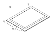
- FIG. 1 is a perspective view showing the appearance of a battery cell
- FIG. 2 is a diagram showing a plan and side surfaces of the battery cell
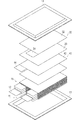
- FIG. 3 is an exploded perspective view of the battery cell.
- the battery cell 10 has a flat rectangular shape, and the positive electrode lead 11 and the negative electrode lead 12 are led out from the same end portion of the exterior material 13.
- the packaging material 13 is, for example, a resin-coated aluminum sheet surface.
- a power generation element (battery element) 15 in which a charge / discharge reaction proceeds and an electrolytic solution are accommodated in the exterior material 13.
- the power generation element 15 is formed by alternately stacking positive electrodes 30 and negative electrodes 40 with a sheet-like separator 20 interposed therebetween. In a state where the power generation element 15 is disposed inside the exterior member 13 and an electrolytic solution is added or the initial charge is performed, air, gas, or the like may accumulate in the battery element 15 (separator 20).
- the positive electrode 30 has a positive electrode active material layer 32 formed on both surfaces of a sheet-like positive electrode current collector.
- the positive electrode active material layer 32 is not formed on the tab portion 34 of the positive electrode 30.
- the tab portions 34 of the positive electrode 30 are provided at overlapping positions when viewed from the stacking direction of the power generation elements 15. The tab portion 34 is connected to the positive electrode lead 11.
- the negative electrode 40 has a negative electrode active material layer 42 formed on both surfaces of a sheet-like negative electrode current collector.
- the negative electrode active material layer 42 is not formed on the tab portion 44 of the negative electrode 40.
- Each tab portion 44 of the negative electrode 40 is provided at a position that overlaps the tab portion 34 of the positive electrode 30 when viewed from the stacking direction of the power generation elements 15.
- the tab portion 44 is connected to the negative electrode lead 12.
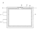
- FIG. 4 is a diagram showing a sealing portion in the battery cell.
- the sealing part 16 shown with the oblique line in the figure is actually invisible from the outside of the battery cell 10, it is clearly shown for explanation of the position.
- the outer packaging material 13 of the battery cell 10 is formed by enclosing a battery element 15 between two rectangular laminate sheets (exterior packaging sheets) and sealing them with a sealing portion 16 along each side of the rectangle. Yes.
- the exterior materials 13 are bonded to each other within a range indicated by oblique lines in FIG.
- the adhesion between the exterior materials 13 can be achieved, for example, by thermally fusing the resins that coat the exterior material 13 or by adhering them with an adhesive.
- the sealing portion 16 is formed to be slightly smaller from a position away from each side of the battery cell 10 by a predetermined distance, that is, from the outer shape of the battery cell 10.
- the sealing portion 16 is formed in a U shape so as to partially approach the side 17 on the side 17 side of the battery cell 10.
- One side of the battery cell 10 is used as a gas vent 18 for discharging air or gas in the exterior material 13.
- the gas vent 18 communicates the interior and exterior of the exterior material 13.
- the gas and the like inside the exterior material 13 are exhausted through the gas vent 18. Thereafter, the battery cell 10 is resealed by bonding the exterior material 13 at the portion of the gas vent 18.
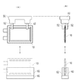
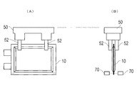
- FIG. 5 is a diagram showing how the battery cells are transported and placed.
- FIG. 5A shows the battery cell 10 viewed from the plane direction
- FIG. 5B shows the battery cell 10 viewed from the arrow 5B direction.
- the battery cell 10 is transported by the transport device 50.
- the transport device 50 of the present embodiment suspends the battery cell 10 and transports it in the air in a state where the rectangular short side of the battery cell 10 stands vertically.
- the transport device 50 is, for example, a transport robot that transports the upper portion of the flat surface of the battery cell 10 by sandwiching the upper portion of the battery cell 10 from both sides by the grip portion 52.
- the transport device 50 transports the battery cell 10 to various processes for processing and processing, and delivers the battery cell 10 to another device or receives it from another device.
- the other device includes, for example, a cradle for temporarily mounting the battery cell 10, a storage device for storing the battery cell 10, and a transport device for transporting the battery cell 10 by a method different from the transport device 50. and so on.
- it may be a processing device or a processing stand for performing predetermined processing on the battery cell 10. Below, the case where the battery cell 10 is delivered to the cradle 60 shown in the lower side in the figure is illustrated.
- the cradle 60 has a support portion 62 that supports the battery cell 10 from both sides.
- the battery cell 10 is transported to above the cradle 60 by the transport device 50, and the battery device 10 is inserted between the support portions 62 of the cradle 60 when the transport device 50 approaches the cradle 60.
- the conveyance device 50 releases the grip by the grip portion 52, the battery cell 10 is stored in the cradle 60.
- the transport device 50 approaches the cradle 60 and grips the battery cell 10 by the grip portion 52.
- the battery cell 10 is taken out from the cradle 60 by raising the transport device 50.
- the battery cell 10 is transported with the gas vent 18 positioned upward, and is stored in the cradle 60 from the side opposite to the gas vent 18. Therefore, the battery cell 10 often comes into contact with other devices such as the cradle 60 on the side opposite to the gas vent 18.
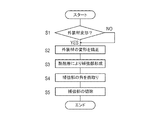
- FIG. 6 is a flowchart showing the procedure of the battery reinforcing method
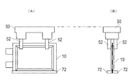
- FIG. 7 is a diagram showing how the battery cell is deformed
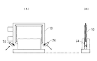
- FIG. 8 is a diagram showing how the reinforcing portion is formed
- FIG. 9 is a reinforcement formed on the battery cell.
- FIG. 10 is a diagram showing a chamfered state of the reinforcing portion.
- the battery cell 10 is transported to a predetermined position by the transport device 50, and it is confirmed whether or not there is any deformation such as bending at a location where the battery cell 10 is reinforced (step S1).
- the sensor 70 shown in FIG. 7 that inspects the deformation.
- the sensor 70 is, for example, a pair of photoelectric sensors, and the deformation of the exterior material 13 of the battery cell 10 is confirmed by detecting the amount of light irradiated from one side on the other side.
- the exterior material 13 often has a side located on the lower side in the drawing in contact with another device, and is often deformed at a corner. Therefore, for example, it is preferable to detect the bending of the corner portion of the exterior member 13 indicated by the dotted line in FIG.
- step S2 When the bending of the exterior material 13 is detected by the sensor 70 (step S1: YES), the deformation is corrected (step S2).
- the correction of bending is, for example, a pressing roller that extends straight while pressing the exterior member 13.
- the deformation of the exterior material 13 may be corrected by any method.
- step S3 the battery cell 10 is formed with a reinforcing portion (step S3).
- the reinforcing portion as shown in FIG. 8, the lower part of the exterior material 13 of the battery cell 10 is heat-sealed by a heat-sealing device 72.
- the pair of blocks are in contact with a portion forming the reinforcing portion of the exterior material 13, and the resin of the exterior material 13 is fused by pressing while heating from both sides.
- the reinforcement part 80 is formed in the edge
- the sealing portion 16 that seals the exterior material 13 can also be formed by thermal fusion, but the reinforcing portion 80 can be formed by thermal fusion with accuracy different from that of the sealing portion 16.
- the sealing portion 16 is formed by high-precision heat fusion, and the reinforcing portion 80 is formed by relatively low-precision heat fusion.
- the corners of the formed reinforcing portion 80 are chamfered (rounded) (step S4).
- the reinforcing portion 80 is chamfered by a flange 74 as shown in FIG.
- the collar 74 approaches the corner of the battery cell 10 placed on the cradle 60 or the like and cuts off the corner.
- the portions painted black in FIGS. 9 and 10 are cut off.
- step S4 the battery cell 10 is transported to each apparatus for processing and the like, and is taken in and out of the cradle 60 and the storage for supporting the battery cell 10 each time.
- the reinforcing portion 80 is cut off from the battery cell 10 (step S5). The reinforcing portion 80 is cut off at a position indicated by a dotted line B in FIG.
- the reinforcing portion 80 is formed on the other side 19 different from the side 17 provided with the gas vent 18 used for gas discharge.
- the side 19 other than the side 17 often comes into contact with other devices such as the transport device 50 and the cradle 60 when the battery cell 10 is transported or supported for processing. Therefore, by reinforcing the side 19, deformation of the exterior material 13 of the battery cell 10 due to contact with another device can be prevented.
- the reinforcement part 80 can be formed without adding another member, an additional cost is not required for the reinforcement part 80, and a deformation
- a reinforcing portion 80 is formed on the outside. Therefore, the reinforcing portion 80 can be formed with a reference or accuracy different from that of the sealing portion 16. Since the reinforcing portion 80 is formed outside the sealing portion 16, the sealing portion 16 can be protected by the reinforcing portion 80 when the battery cell 10 is transported.
- the formation of the sealing portion 16 and the reinforcing portion 80 can be achieved by thermally fusing the resin of the laminate sheet separately, so that the sealing portion 16 and the reinforcing portion 80 are separately used while using the laminate sheet having the same configuration. Can be formed.
- the deformation of the exterior material 13 is detected by the sensor 70 before the reinforcing portion 80 is formed, the deformation of the side can be reliably detected.
- the reinforcing portion 80 is formed on the side 19 of the battery cell 10 that comes into contact with another device such as the cradle 60, deformation of the exterior material 13 of the battery cell 10 due to contact with the other device can be prevented.
- the corner of the side 19 reinforced by the reinforcing portion 80 is chamfered, when the battery cell 10 is inserted from the side 19 where the battery cell 10 is reinforced into another device such as the cradle 60, the load on the corner is dispersed and the side 19 is deformed. Can be prevented.
- the reinforcing portion 80 is provided to prevent the outer packaging material 13 of the battery cell 10 from being deformed, while the reinforcing portion 80 is finally cut off. Therefore, the reinforcing portion 80 that is reinforced by a process such as processing and has some damage does not remain in the battery cell 10 as the final product. Therefore, the battery cell 10 without any scratches can be obtained.
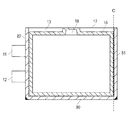
- FIG. 11 is a view showing a battery cell in which a reinforcing portion is further formed.
- the reinforcing portion 80 is formed along the side 19 of the battery cell 10.
- the reinforcing portions 81 and 82 may be formed on the vertically standing side.
- the reinforcing portions 81 and 82 are formed in the same manner as described above.
- the reinforcing portions 81 and 82 are formed by heat-sealing a resin of a laminate sheet. Note that the reinforcing portion 81 can be cut off at the position indicated by the dotted line C before the battery cell 10 is shipped. In FIG.
- the reinforcing portion 82 is also formed on the side where the positive electrode lead 11 and the negative electrode lead 12 are drawn, but the reinforcing portion 82 cannot be excised and is left as it is. Since there is the positive electrode lead 11 and the like on the reinforcing portion 82 side, the reinforcing portion 82 is not damaged so much, and there is no problem even if the reinforcing portion 82 is left.
- the said embodiment demonstrated the example which mounts the battery cell 10 in the cradle 60, and takes out the battery cell 10 from the cradle 60, it is not limited to this.
- the reinforcement of the battery cell 10 is also effective when the battery cell 10 is delivered to a storage rack that stores a plurality of battery cells 10 or the battery cell is taken out from the storage rack.
Landscapes
- Chemical & Material Sciences (AREA)
- Chemical Kinetics & Catalysis (AREA)
- Electrochemistry (AREA)
- General Chemical & Material Sciences (AREA)
- Inorganic Chemistry (AREA)
- Sealing Battery Cases Or Jackets (AREA)
Abstract
【課題】電池セルの端部が破損しないように補強する電池補強方法を提供する。 【解決手段】電池補強方法は、矩形の外装材13内に電池要素が配置された矩形電池セル10を補強するための電池補強方法であって、外装材13を、2枚の矩形の外装材シートの間に電池要素15を内包して、矩形の各辺に沿う封止部16により封止することによって形成し、外装材13において封止部16よりも外側に補強部80を形成する工程(ステップS3)を含む電池補強方法。
Description
本発明は、電池補強方法に関する。
複数のワークをラック内に収納し、ワークの処理工程に応じて、ラック内に配列されている複数のワークのピッチを調整する技術が知られている(たとえば、特許文献1参照)。特許文献1記載の発明では、ワークが基板であり、基板保持部材に形成された溝に、基板の端部を嵌め合せた状態で、ワークが保持される。
一方、電池セルを加工する工程においても、複数の電池セルをラックに収納し、必要に応じてピッチを調整して、取り出したり搬送したりすることが考えられる。
しかしながら、電池セルの場合、たとえばアルミシートを樹脂でコーティングしたラミネートシートにより外装が形成されているので、外装の端部が基板ほど硬くない。したがって、特許文献1記載の方法を採用すると、電池セルを保持部材の溝に嵌め合せる際に、外装を破損する虞がある。
特許文献1のように保持部材の溝にワークを嵌め合せる形態でなくても、電池セルを所定のラック等の収納に出し入れする場合でも、電池セルの外装を破損する虞がある。
本発明は、上記事情に鑑みてなされたものであり、電池セルの端部が破損しないように補強する電池補強方法を提供することを目的とする。
電池補強方法は、矩形の外装材内に電池要素が配置された矩形電池セルを補強するための電池補強方法である。外装材は、2枚の矩形の外装材シートの間に前記電池要素を内包して、矩形の各辺に沿う封止部により封止することによって形成される。電池補強方法は、外装材において封止部よりも外側に補強部を形成する工程を含む。
電池補強方法は、封止部とは別に補強部を外側に形成する。したがって、電池セルの搬送時等に封止部を補強部により保護できる。
以下、添付した図面を参照して、本発明の実施形態を説明する。なお、図面の説明において同一の要素には同一の符号を付し、重複する説明を省略する。また、図面の寸法比率は、説明の都合上誇張されており、実際の比率とは異なる場合がある。
本発明は、電池セルを補強する電池セル補強方法に関する。電池セル補強方法を説明する前に、補強対象である電池の構造について説明する。
(電池)
図1は電池セルの外観を表した斜視図、図2は電池セルの平面および側面を示す図、図3は電池セルの分解斜視図である。
図1は電池セルの外観を表した斜視図、図2は電池セルの平面および側面を示す図、図3は電池セルの分解斜視図である。
図1および図2に示すとおり、電池セル10は、扁平な矩形形状を有しており、正極リード11および負極リード12が外装材13の同一端部から導出されている。外装材13は、たとえば、アルミシートの表面を樹脂コーティングしたものである。
外装材13の内部には、図3に示すように、充放電反応が進行する発電要素(電池要素)15および電解液が収容されている。発電要素15は、間にシート状のセパレータ20を挟みつつ、正極30と、負極40とが交互に積層されて形成される。発電要素15を外装材13内部に配置し電解液を加えた状態や初回充電を行った状態では、電池要素15内部(セパレータ20)に空気やガスなどが溜まることがある。
正極30は、シート状の正極集電体の両面に正極活物質層32が形成されてなる。正極活物質層32は、正極30のタブ部分34には形成されていない。正極30の各タブ部分34は、発電要素15の積層方向から見て、重なる位置に設けられている。タブ部分34は、正極リード11と接続される。
負極40は、シート状の負極集電体の両面に負極活物質層42が形成されてなる。負極活物質層42は、負極40のタブ部分44には形成されていない。負極40の各タブ部分44は、発電要素15の積層方向から見て、重なる位置であって、正極30のタブ部分34とは重ならない位置に設けられている。タブ部分44は、負極リード12と接続される。
図4は、電池セル内の封止部を示す図である。なお、図中斜線で示す封止部16は、電池セル10の外部からは実際は目視できないものであるが、位置の説明のため明示している。
電池セル10の外装材13は、2枚の矩形のラミネートシート(外装材シート)間に電池要素15を内包して、矩形の各辺に沿う封止部16により封止することで形成されている。たとえば、図4に斜線で示す範囲で、外装材13同士が接着され、封止部16が形成される。外装材13同士の接着は、たとえば、外装材13をコーティングする樹脂同士を熱融着させたり、接着剤により接着させたりすることで達成できる。封止部16は、電池セル10の各辺から所定の距離離れた位置、すなわち、電池セル10の外形から一回り小さく形成される。ただし、封止部16は、電池セル10の1辺17側においては、一部で辺17に接近するようにコの字に形成されている。辺17は、電池セル10の1辺は外装材13内の空気やガスを排出するためのガス抜き口18として使用される。図中点線Aで示される位置で、電池セル10の1辺17が切り落とされると、ガス抜き口18は、外装材13内部と外部を連通する。ガス抜き口18を通じて、外装材13内部のガス等が排出される。その後、ガス抜き口18の部分で、外装材13が接着されることで、電池セル10が再封止される。
電池セル10が搬送、収納される様子を説明する。
図5は、電池セルが搬送および載置される様子を示す図である。図5(A)は電池セル10の平面方向から見た様子を示し、図5(B)は図5(A)の矢印5B方向から見た様子を示す。
図5に示すように、電池セル10は、搬送装置50により搬送される。本実施形態の搬送装置50は、電池セル10の矩形の短辺を垂直に立てた状態で、電池セル10を吊り下げて空中搬送する。搬送装置50は、たとえば、電池セル10の平面の上部を両側から把持部52により挟んで搬送する搬送ロボットである。
搬送装置50は、加工や処理のための種々の工程まで電池セル10を搬送し、他の装置に電池セル10を受け渡したり、他の装置から受け取ったりする。ここで、他の装置には、たとえば、一時的に電池セル10を載置する受け台、電池セル10を収納する収納装置、搬送装置50とは別の方法で電池セル10を搬送する搬送装置などがある。あるいは、電池セル10に所定の加工を施すための加工装置や加工台であってもよい。以下では、図中下側に示す受け台60に電池セル10が受け渡し等される場合について例示する。
受け台60は、電池セル10を両面から支持する支持部62を有する。電池セル10が搬送装置50により受け台60の上方まで搬送され、搬送装置50が受け台60に接近することよって、電池セル10が受け台60の支持部62間に挿入される。搬送装置50が把持部52により把持を開放すると、受け台60に電池セル10が収納される。電池セル10が受け台60から取り出される際には、受け台60に搬送装置50が接近し、電池セル10を把持部52により把持する。搬送装置50が上昇することで、受け台60から電池セル10が取り出される。
上記のように、本実施形態では、電池セル10は、ガス抜き口18を上方に位置させた状態で搬送され、ガス抜き口18とは反対の辺から受け台60に収納される。したがって、電池セル10は、ガス抜き口18とは反対の辺で受け台60等の他の装置と接触することが多い。
(電池補強方法)
以下、ガス抜き口18が開口される前の状態、すなわち、図4に示す状態で、電池セル10が補強される方法について、詳細に説明する。
以下、ガス抜き口18が開口される前の状態、すなわち、図4に示す状態で、電池セル10が補強される方法について、詳細に説明する。
図6は電池補強方法の手順を示すフローチャート、図7は電池セルの変形を確認する様子を示す図、図8は補強部を形成する様子を示す図、図9は電池セルに形成された補強部を示す図、図10は補強部の面取りの様子を示す図である。
まず、搬送装置50により電池セル10が所定位置に搬送され、電池セル10の補強する箇所に折れ曲がり等の変形がないか確認される(ステップS1)。ここで、変形を検査するのは、図7に示すセンサ70である。センサ70は、たとえば、一対の光電センサであり、一方から照射した光の光量を他方で検出することによって、電池セル10の外装材13の変形を確認する。外装材13は、図5で説明したように、図中下側に位置する辺が他の装置と接触することが多く、特に角で変形することが多い。したがって、たとえば、図7中点線で示す外装材13の角の部分について、曲がりを検出することが好ましい。
外装材13の曲がりがセンサ70により検出された場合(ステップS1:YES)、当該変形は矯正される(ステップS2)。曲がりの矯正は、たとえば、外装材13を押圧しながら真っ直ぐに伸ばす押圧ローラである。ただし、外装材13の変形は、いかなる方法により矯正されてもよい。
続けて、曲がりがないことが確認された場合(ステップS1:NO)、または、曲がりが矯正された場合(ステップS2)、電池セル10は、補強部が形成される(ステップS3)。補強部を形成する際には、図8に示すように、電池セル10の外装材13の下部を、熱融着装置72により熱融着する。熱融着装置72は、対となるブロックが外装材13の補強部を形成する部分に当接し、両側から加熱しつつ押圧することで、外装材13の樹脂を融着する。図9に示すように、電池セル10の封止部16よりも外側であって、ガス抜き口18が形成された辺17とは異なる辺19に補強部80が形成される。なお、外装材13を封止する封止部16も熱融着により形成されうるが、補強部80は、封止部16とは異なる精度の熱融着により形成できる。たとえば、封止部16は高精度な熱融着により形成され、補強部80は比較的低精度な熱融着により形成される。
続けて、電池セル10は、形成された補強部80の角が面取りされる(丸められる)(ステップS4)。補強部80は、図10に示すように、鋏74により面取りされる。鋏74は、受け台60等に載置された電池セル10の角に接近して、角を切り落とす。図9および図10の黒く塗られた部分が切り落とされる。
ステップS4後には、電池セル10は加工等の各装置に搬送され、その度に、電池セル10を支持する受け台60や収納に出し入れされる。電池セル10の主な加工等が終了した後で、製品として電池セル10が出荷される前には、補強部80は電池セル10から切除される(ステップS5)。補強部80は、図9の点線Bで示される位置で、切り落とされる。
以上のように、上記実施形態では、気体排出に使用されるガス抜き口18が設けられた辺17とは異なる他の辺19に補強部80を形成している。辺17以外の辺19は、上述のように、電池セル10を搬送する際や加工のために支持する際に、搬送装置50や受け台60などの他の装置と接触することが多い。したがって、辺19を補強することによって、他の装置との接触により電池セル10の外装材13の変形を防止できる。また、補強部80は、別部材を付加することなく形成できるので、補強部80のために別途のコストが必要なく、低コストに変形の防止を実現できる。
また、外装材13のラミネートシートの封止部16とは別に、補強部80を外側に形成している。したがって、封止部16とは異なる基準ないし精度で補強部80を形成できる。封止部16とは別に補強部80を外側に形成するので、電池セル10の搬送時等に封止部16を補強部80により保護できる。
封止部16および補強部80の形成は、それぞれ別個にラミネートシートの樹脂を熱融着することにより達成できるので、同じ構成のラミネートシートを使用しつつ、別個に封止部16および補強部80を形成できる。
また、補強部80を形成する前に、外装材13の変形を矯正するので、外装材13の辺が変形したまま補強部80を形成することにより辺に不要な癖や折目がつくのを防止できる。
補強部80を形成する前に、外装材13の変形をセンサ70により検出するので、確実に辺の変形を検出できる。
補強部80は、受け台60等の他の装置と接触する電池セル10の辺19に形成されるので、他の装置との接触による電池セル10の外装材13の変形を防止できる。
補強部80により補強した辺19の角を面取りするので、電池セル10を補強した辺19から受け台60等の他の装置に挿入する場合に、角への負荷を分散し、辺19の変形を防止できる。
電池セル10の加工等の工程においては補強部80を設けておき、電池セル10の外装材13の変形を防止する一方で、最終的には補強部80を切除する。したがって、加工等の工程により補強されつつも多少の傷がついた補強部80は、最終製品としての電池セル10には残らない。したがって、全く傷のない電池セル10を得られる。
以上、本実施形態について説明してきたが、本発明は上記実施形態に限定されない。種々の改良が可能である。
図11は、さらに補強部を形成した電池セルを示す図である。
上記実施形態では、電池セル10の辺19に沿った補強部80を形成していた。しかし、これに限定されない。図11に示すように、垂直に立つ辺にも補強部81、82を形成してもよい。補強部81、82の形成の仕方は、上記と同様であり、たとえば、ラミネートシートの樹脂を熱融着して形成する。なお、電池セル10の出荷前には、点線Cで示す位置で補強部81を切除できる。なお、図11では、正極リード11および負極リード12が引き出されている辺にも補強部82が形成されているが、補強部82は切除できないので、そのまま残す。補強部82側は、正極リード11等があるので、破損することは余りないので、補強部82を残しても問題はない。
また上記実施形態では、受け台60に電池セル10を載置したり、受け台60から電池セル10を取り出したりする例について説明したがこれに限定されない。複数の電池セル10を収納する収納ラックに電池セル10を受け渡したり、収納ラックから電池セルを取り出すような場合にも、上記電池セル10の補強は有効である。
本出願は、2012年2月13日に出願された日本特許出願番号2012-28515号に基づいており、それらの開示内容は、参照され、全体として、組み入れられている。
10 電池セル、
11 正極リード、
12 負極リード、
13 外装材、
15 電池要素、
16 封止部、
17、19 辺、
18 ガス抜き口、
20 セパレータ、
30 正極、
40 負極、
50 搬送装置、
52 把持部、
60 受け台、
62 支持部、
70 センサ、
72 熱融着装置、
74 鋏、
80、81、82 補強部。
11 正極リード、
12 負極リード、
13 外装材、
15 電池要素、
16 封止部、
17、19 辺、
18 ガス抜き口、
20 セパレータ、
30 正極、
40 負極、
50 搬送装置、
52 把持部、
60 受け台、
62 支持部、
70 センサ、
72 熱融着装置、
74 鋏、
80、81、82 補強部。
Claims (8)
- 矩形の外装材内に電池要素が配置された矩形電池セルを補強するための電池補強方法であって、
前記外装材を、2枚の矩形の外装材シートの間に前記電池要素を内包して、矩形の各辺に沿う封止部により封止することによって形成し、
前記外装材において前記封止部よりも外側に補強部を形成する工程を含む電池補強方法。 - 前記補強部を、前記外装材シートの気体を排出するために使用される矩形の1辺とは異なる他の辺の少なくとも一部に形成する請求項1に記載の電池補強方法。
- 前記外装材シートは、金属シートを樹脂により被覆したものであり、
前記封止部および前記補強部の形成は、それぞれ別個に、2枚の前記外装材シートを被覆する樹脂を熱圧着することによって達成される請求項1または請求項2記載の電池補強方法。 - 前記電池セルの辺の少なくとも一部に前記補強部を形成する工程の前に、前記辺の補強部を形成する部分の変形を矯正する工程をさらに含む請求項1~3のいずれか一項に記載の電池補強方法。
- 前記電池セルの辺の少なくとも一部に前記補強部を形成する工程の前に、前記辺の補強部を形成する部分の変形を検出する工程をさらに含む請求項1~4のいずれか一項に記載の電池補強方法。
- 前記補強部は、前記電池セルを他の装置に受け渡しまたは他の装置から受け取る際に、当該他の装置と接触する前記電池セルの辺に形成される請求項1~5のいずれか一項に記載の電池補強方法。
- 前記補強部により補強した辺の角を面取りする工程をさらに含む請求項1~6のいずれか一項に記載の電池補強方法。
- 前記電池セルの辺の前記補強部が形成された部分を切断する工程をさらに含む請求項1~7のいずれか一項に記載の電池補強方法。
Priority Applications (3)
| Application Number | Priority Date | Filing Date | Title |
|---|---|---|---|
| US14/376,649 US9553285B2 (en) | 2012-02-13 | 2013-02-13 | Battery reinforcement method |
| EP13748485.3A EP2816631B1 (en) | 2012-02-13 | 2013-02-13 | Battery reinforcement method |
| CN201380008850.XA CN104115302B (zh) | 2012-02-13 | 2013-02-13 | 电池加强方法 |
Applications Claiming Priority (2)
| Application Number | Priority Date | Filing Date | Title |
|---|---|---|---|
| JP2012028515A JP5909378B2 (ja) | 2012-02-13 | 2012-02-13 | 電池補強方法 |
| JP2012-028515 | 2012-02-13 |
Publications (1)
| Publication Number | Publication Date |
|---|---|
| WO2013122097A1 true WO2013122097A1 (ja) | 2013-08-22 |
Family
ID=48984206
Family Applications (1)
| Application Number | Title | Priority Date | Filing Date |
|---|---|---|---|
| PCT/JP2013/053381 WO2013122097A1 (ja) | 2012-02-13 | 2013-02-13 | 電池補強方法 |
Country Status (5)
| Country | Link |
|---|---|
| US (1) | US9553285B2 (ja) |
| EP (1) | EP2816631B1 (ja) |
| JP (1) | JP5909378B2 (ja) |
| CN (1) | CN104115302B (ja) |
| WO (1) | WO2013122097A1 (ja) |
Families Citing this family (2)
| Publication number | Priority date | Publication date | Assignee | Title |
|---|---|---|---|---|
| US9837682B1 (en) | 2016-08-29 | 2017-12-05 | Microsoft Technology Licensing, Llc | Variable layer thickness in curved battery cell |
| KR20220062995A (ko) * | 2020-11-09 | 2022-05-17 | 주식회사 엘지에너지솔루션 | 이차 전지 |
Citations (5)
| Publication number | Priority date | Publication date | Assignee | Title |
|---|---|---|---|---|
| JPH07183357A (ja) | 1993-12-22 | 1995-07-21 | Dainippon Screen Mfg Co Ltd | 基板配列ピッチ変換装置 |
| JP2005347123A (ja) * | 2004-06-03 | 2005-12-15 | Toshiba Corp | 薄型非水電解質二次電池 |
| WO2006098242A1 (ja) * | 2005-03-17 | 2006-09-21 | Nec Corporation | フィルム外装電気デバイスおよびその製造方法 |
| JP2010198988A (ja) * | 2009-02-26 | 2010-09-09 | Sumitomo Chemical Co Ltd | フィルムケース型蓄電デバイス |
| JP2012204002A (ja) * | 2011-03-23 | 2012-10-22 | Nec Tokin Corp | 蓄電デバイス |
Family Cites Families (7)
| Publication number | Priority date | Publication date | Assignee | Title |
|---|---|---|---|---|
| GB2087779B (en) * | 1980-11-20 | 1985-05-15 | Rhodes Joseph Ltd | Metal trimmer |
| JP3709134B2 (ja) * | 2000-11-22 | 2005-10-19 | 松下電器産業株式会社 | 角形電池 |
| ATE550636T1 (de) * | 2004-05-12 | 2012-04-15 | Pirelli | Verfahren zur bestimmung einer kraft an der nabe eines rads eines fahrzeugs während der fahrt und für die ausführung des verfahrens geeignetes rad |
| JP5108411B2 (ja) * | 2007-08-03 | 2012-12-26 | パナソニック株式会社 | 電池缶およびその製造方法並びに製造装置 |
| US20090169977A1 (en) * | 2007-12-31 | 2009-07-02 | Apple Inc. | Systems and methods for monitoring and responding to forces influencing a battery |
| DE102008047615A1 (de) * | 2008-09-17 | 2010-04-15 | Li-Tec Battery Gmbh | Akkumulator |
| US8771866B2 (en) * | 2010-03-30 | 2014-07-08 | Samsung Sdi Co., Ltd. | Pouch type secondary battery and the fabrication method thereof |
-
2012
- 2012-02-13 JP JP2012028515A patent/JP5909378B2/ja active Active
-
2013
- 2013-02-13 WO PCT/JP2013/053381 patent/WO2013122097A1/ja active Application Filing
- 2013-02-13 US US14/376,649 patent/US9553285B2/en active Active
- 2013-02-13 CN CN201380008850.XA patent/CN104115302B/zh active Active
- 2013-02-13 EP EP13748485.3A patent/EP2816631B1/en active Active
Patent Citations (5)
| Publication number | Priority date | Publication date | Assignee | Title |
|---|---|---|---|---|
| JPH07183357A (ja) | 1993-12-22 | 1995-07-21 | Dainippon Screen Mfg Co Ltd | 基板配列ピッチ変換装置 |
| JP2005347123A (ja) * | 2004-06-03 | 2005-12-15 | Toshiba Corp | 薄型非水電解質二次電池 |
| WO2006098242A1 (ja) * | 2005-03-17 | 2006-09-21 | Nec Corporation | フィルム外装電気デバイスおよびその製造方法 |
| JP2010198988A (ja) * | 2009-02-26 | 2010-09-09 | Sumitomo Chemical Co Ltd | フィルムケース型蓄電デバイス |
| JP2012204002A (ja) * | 2011-03-23 | 2012-10-22 | Nec Tokin Corp | 蓄電デバイス |
Non-Patent Citations (1)
| Title |
|---|
| See also references of EP2816631A4 |
Also Published As
| Publication number | Publication date |
|---|---|
| CN104115302A (zh) | 2014-10-22 |
| JP5909378B2 (ja) | 2016-04-26 |
| EP2816631A1 (en) | 2014-12-24 |
| US9553285B2 (en) | 2017-01-24 |
| JP2013165038A (ja) | 2013-08-22 |
| CN104115302B (zh) | 2017-12-01 |
| EP2816631B1 (en) | 2021-03-24 |
| US20150026969A1 (en) | 2015-01-29 |
| EP2816631A4 (en) | 2015-07-29 |
Similar Documents
| Publication | Publication Date | Title |
|---|---|---|
| EP3588653B1 (en) | Method for producing mono-cell | |
| KR101719030B1 (ko) | 필름 외장 전지 및 그 선별 방법 | |
| TWI472080B (zh) | A position detecting device and a position detecting method | |
| JP6638593B2 (ja) | 電極組立体の製造方法 | |
| JP5521861B2 (ja) | 電極積層装置 | |
| WO2012137903A1 (ja) | 袋詰電極の製造装置、および袋詰電極の製造方法 | |
| JP6597029B2 (ja) | 積層装置 | |
| KR20190045602A (ko) | 이차전지용 라미네이션 장치 및 방법 | |
| JP6481258B2 (ja) | 電気デバイスのセパレータ接合方法、電気デバイスのセパレータ接合装置、および電気デバイス | |
| JP5909378B2 (ja) | 電池補強方法 | |
| JP6642072B2 (ja) | 二次電池の製造装置および二次電池の製造方法 | |
| TWI494211B (zh) | Bonding device and joining method | |
| WO2020110207A1 (ja) | 位置決め搬送装置および位置決め搬送方法 | |
| JP6044635B2 (ja) | 基板用包装ならびにそのような包装を備える包装ユニット | |
| KR102253132B1 (ko) | 2차 전지용 단위 셀 제조 방법, 장치 및 시스템 | |
| JP6075256B2 (ja) | 電極の製造方法及び電極の製造装置 | |
| JP6575940B2 (ja) | 袋詰電極の製造装置、および袋詰電極の製造方法 | |
| JP2019139961A (ja) | 積層電極体の製造装置 | |
| WO2018127994A1 (ja) | 電極体の製造方法 | |
| US20210013481A1 (en) | Battery Stack Forming Apparatus and Battery Stack Forming Method | |
| JP6561585B2 (ja) | 搬送装置 | |
| JP2019050096A (ja) | バイポーラ電極の製造方法及びバイポーラ電極の製造装置 | |
| JP2019057476A (ja) | 蓄電モジュールの製造方法及び製造装置 | |
| KR20230127806A (ko) | 전극조립체 제조 시스템 및 제조 방법 | |
| JP6298675B2 (ja) | 接着剤塗布装置 |
Legal Events
| Date | Code | Title | Description |
|---|---|---|---|
| 121 | Ep: the epo has been informed by wipo that ep was designated in this application |
Ref document number: 13748485 Country of ref document: EP Kind code of ref document: A1 |
|
| DPE1 | Request for preliminary examination filed after expiration of 19th month from priority date (pct application filed from 20040101) | ||
| WWE | Wipo information: entry into national phase |
Ref document number: 2013748485 Country of ref document: EP |
|
| WWE | Wipo information: entry into national phase |
Ref document number: 14376649 Country of ref document: US |
|
| NENP | Non-entry into the national phase |
Ref country code: DE |