WO2013118719A1 - 燃料電池スタック及び燃料電池システム - Google Patents
燃料電池スタック及び燃料電池システム Download PDFInfo
- Publication number
- WO2013118719A1 WO2013118719A1 PCT/JP2013/052604 JP2013052604W WO2013118719A1 WO 2013118719 A1 WO2013118719 A1 WO 2013118719A1 JP 2013052604 W JP2013052604 W JP 2013052604W WO 2013118719 A1 WO2013118719 A1 WO 2013118719A1
- Authority
- WO
- WIPO (PCT)
- Prior art keywords
- fuel cell
- cell stack
- extending member
- internal manifold
- anode
- Prior art date
Links
Images


Classifications
-
- H—ELECTRICITY
- H01—ELECTRIC ELEMENTS
- H01M—PROCESSES OR MEANS, e.g. BATTERIES, FOR THE DIRECT CONVERSION OF CHEMICAL ENERGY INTO ELECTRICAL ENERGY
- H01M8/00—Fuel cells; Manufacture thereof
- H01M8/24—Grouping of fuel cells, e.g. stacking of fuel cells
- H01M8/2465—Details of groupings of fuel cells
- H01M8/2483—Details of groupings of fuel cells characterised by internal manifolds
-
- H—ELECTRICITY
- H01—ELECTRIC ELEMENTS
- H01M—PROCESSES OR MEANS, e.g. BATTERIES, FOR THE DIRECT CONVERSION OF CHEMICAL ENERGY INTO ELECTRICAL ENERGY
- H01M8/00—Fuel cells; Manufacture thereof
- H01M8/04—Auxiliary arrangements, e.g. for control of pressure or for circulation of fluids
- H01M8/04082—Arrangements for control of reactant parameters, e.g. pressure or concentration
- H01M8/04089—Arrangements for control of reactant parameters, e.g. pressure or concentration of gaseous reactants
- H01M8/04119—Arrangements for control of reactant parameters, e.g. pressure or concentration of gaseous reactants with simultaneous supply or evacuation of electrolyte; Humidifying or dehumidifying
- H01M8/04156—Arrangements for control of reactant parameters, e.g. pressure or concentration of gaseous reactants with simultaneous supply or evacuation of electrolyte; Humidifying or dehumidifying with product water removal
- H01M8/04171—Arrangements for control of reactant parameters, e.g. pressure or concentration of gaseous reactants with simultaneous supply or evacuation of electrolyte; Humidifying or dehumidifying with product water removal using adsorbents, wicks or hydrophilic material
-
- H—ELECTRICITY
- H01—ELECTRIC ELEMENTS
- H01M—PROCESSES OR MEANS, e.g. BATTERIES, FOR THE DIRECT CONVERSION OF CHEMICAL ENERGY INTO ELECTRICAL ENERGY
- H01M8/00—Fuel cells; Manufacture thereof
- H01M8/24—Grouping of fuel cells, e.g. stacking of fuel cells
- H01M8/241—Grouping of fuel cells, e.g. stacking of fuel cells with solid or matrix-supported electrolytes
- H01M8/242—Grouping of fuel cells, e.g. stacking of fuel cells with solid or matrix-supported electrolytes comprising framed electrodes or intermediary frame-like gaskets
-
- H—ELECTRICITY
- H01—ELECTRIC ELEMENTS
- H01M—PROCESSES OR MEANS, e.g. BATTERIES, FOR THE DIRECT CONVERSION OF CHEMICAL ENERGY INTO ELECTRICAL ENERGY
- H01M8/00—Fuel cells; Manufacture thereof
- H01M8/24—Grouping of fuel cells, e.g. stacking of fuel cells
- H01M8/2465—Details of groupings of fuel cells
-
- H—ELECTRICITY
- H01—ELECTRIC ELEMENTS
- H01M—PROCESSES OR MEANS, e.g. BATTERIES, FOR THE DIRECT CONVERSION OF CHEMICAL ENERGY INTO ELECTRICAL ENERGY
- H01M8/00—Fuel cells; Manufacture thereof
- H01M8/10—Fuel cells with solid electrolytes
- H01M2008/1095—Fuel cells with polymeric electrolytes
-
- H—ELECTRICITY
- H01—ELECTRIC ELEMENTS
- H01M—PROCESSES OR MEANS, e.g. BATTERIES, FOR THE DIRECT CONVERSION OF CHEMICAL ENERGY INTO ELECTRICAL ENERGY
- H01M8/00—Fuel cells; Manufacture thereof
- H01M8/04—Auxiliary arrangements, e.g. for control of pressure or for circulation of fluids
- H01M8/04291—Arrangements for managing water in solid electrolyte fuel cell systems
-
- H—ELECTRICITY
- H01—ELECTRIC ELEMENTS
- H01M—PROCESSES OR MEANS, e.g. BATTERIES, FOR THE DIRECT CONVERSION OF CHEMICAL ENERGY INTO ELECTRICAL ENERGY
- H01M8/00—Fuel cells; Manufacture thereof
- H01M8/24—Grouping of fuel cells, e.g. stacking of fuel cells
- H01M8/2465—Details of groupings of fuel cells
- H01M8/2484—Details of groupings of fuel cells characterised by external manifolds
- H01M8/2485—Arrangements for sealing external manifolds; Arrangements for mounting external manifolds around a stack
-
- Y—GENERAL TAGGING OF NEW TECHNOLOGICAL DEVELOPMENTS; GENERAL TAGGING OF CROSS-SECTIONAL TECHNOLOGIES SPANNING OVER SEVERAL SECTIONS OF THE IPC; TECHNICAL SUBJECTS COVERED BY FORMER USPC CROSS-REFERENCE ART COLLECTIONS [XRACs] AND DIGESTS
- Y02—TECHNOLOGIES OR APPLICATIONS FOR MITIGATION OR ADAPTATION AGAINST CLIMATE CHANGE
- Y02E—REDUCTION OF GREENHOUSE GAS [GHG] EMISSIONS, RELATED TO ENERGY GENERATION, TRANSMISSION OR DISTRIBUTION
- Y02E60/00—Enabling technologies; Technologies with a potential or indirect contribution to GHG emissions mitigation
- Y02E60/30—Hydrogen technology
- Y02E60/50—Fuel cells
Definitions
- the present invention relates to a fuel cell stack configured by stacking a plurality of fuel cells, and a fuel cell system having the fuel cell stack.
- a fuel cell is configured by sandwiching an electrolyte membrane between an anode electrode and a cathode electrode, and generating electricity using an anode gas containing hydrogen supplied to the anode electrode and a cathode gas containing oxygen supplied to the cathode electrode.
- the electrochemical reactions that proceed at both the anode and cathode electrodes are as follows.
- the fuel cell produces an electromotive force of about 1 V (volt) by the electrochemical reaction of (1) and (2).
- a fuel cell When such a fuel cell is used as a power source for an automobile, since a large amount of power is required, it is used as a fuel cell stack in which several hundred fuel cells are stacked. Then, a fuel cell system for supplying the anode gas and the cathode gas to the fuel cell stack is configured to extract electric power for driving the vehicle.
- JP2006-66131A discloses a fuel cell stack provided with an internal manifold which is a passage for flowing anode gas and cathode gas. These internal manifolds are configured in a passage shape by connecting through holes formed in the fuel cell in the stacking direction of the fuel cell.
- Product water generated at the time of power generation or the like flows into an exhaust side internal manifold that discharges the anode gas and the cathode gas out of the fuel cell stack.
- the generated water remains in the discharge-side internal manifold and returns to the reaction surface (active area), the power generation performance of the fuel cell stack is degraded. Therefore, it is desirable that the internal manifold on the discharge side be configured to easily discharge the generated water.
- the present invention has been made in view of the above-described problems, and an object of the present invention is to provide a fuel cell stack capable of enhancing the discharge performance of generated water in the stacking direction in the internal manifold.
- a fuel cell stack in a fuel cell stack provided with an internal manifold that extends in the stacking direction by stacking a plurality of fuel cells and discharges the gas used in the fuel cell to the outside, A fuel cell stack is provided that includes an extending member extending in the stacking direction in contact with the inner wall surface.
- FIG. 1 is a schematic block diagram of a fuel cell system provided with a fuel cell stack according to a first embodiment of the present invention.
- FIG. 2 is a timing chart for explaining an anode pulsating operation in the fuel cell system.
- FIG. 3 is an exploded view of a fuel cell stack.
- FIG. 4A is a front view of a membrane electrode assembly.
- FIG. 4B is a front view of the anode separator.
- FIG. 4C is a front view of a cathode separator.
- FIG. 5 is an enlarged view of the vicinity of the discharge-side internal manifold of the membrane electrode assembly.
- FIG. 6 is a perspective view of an extending member provided in an internal manifold of a fuel cell stack.
- FIG. 7 is a schematic side view of a fuel cell stack.
- FIG. 8 is a longitudinal sectional view of an extending member provided in the fuel cell stack according to the fourth embodiment.
- FIG. 9 is a top view of the extending member provided in the fuel cell stack according to the fifth embodiment.
- FIG. 10 is a longitudinal sectional view of an extending member provided in the fuel cell stack according to the sixth embodiment.
- FIG. 11A is a view showing a modified example of the upper surface of the inner wall of the extending member.
- FIG. 11B is a view showing a modified example of the upper surface of the inner wall of the extending member.
- FIG. 11C is a view showing a modified example of the upper surface of the inner wall of the extending member.
- FIG. 11A is a view showing a modified example of the upper surface of the inner wall of the extending member.
- FIG. 11B is a view showing a modified example of the upper surface of the inner wall of the extending member.
- FIG. 11C is
- FIG. 11D is a view showing a modified example of the upper surface of the inner wall of the extending member.
- FIG. 11E is a view showing a modified example of the upper surface of the inner wall of the extending member.
- FIG. 12 is a view showing a modified example of the projecting portion formed on the bottom surface of the inner wall of the extending member.
- FIG. 13 is a longitudinal sectional view of an extending member provided in a fuel cell stack according to a seventh embodiment.
- FIG. 14 is a view for explaining the effect of the fuel cell stack according to the seventh embodiment.
- FIG. 15 is a longitudinal sectional view of an extending member and a shock absorbing material provided in a fuel cell stack according to an eighth embodiment.
- FIG. 16 is a longitudinal sectional view of an extending member and a sliding member provided in a fuel cell stack according to a ninth embodiment.
- FIG. 17 is a schematic cross-sectional view of a fuel cell stack provided with an extending member according to a tenth embodiment.
- FIG. 18A is a longitudinal sectional view of an extending member provided in a fuel cell stack according to a tenth embodiment.
- FIG. 18B is a longitudinal cross-sectional view of the extending member of the fuel cell stack according to the tenth embodiment.
- FIG. 19 is a view showing a modification of the tenth embodiment.
- FIG. 20 is a schematic cross-sectional view of a fuel cell stack according to an eleventh embodiment.
- 21 is a cross-sectional view of the extending member taken along the line XX-XX in FIG.
- FIG. 22 is a view showing an extending member according to a modification of the seventh embodiment.
- FIG. 1 is a schematic block diagram of a fuel cell system 1 provided with a fuel cell stack 10 according to a first embodiment of the present invention.
- the fuel cell system 1 includes a fuel cell stack 10, an anode gas supply device 2, a cathode gas supply device 3, a cooling device 4, an inverter 5, a drive motor 6, a battery 7, and a DC / DC converter 8. , And a controller 60.
- the fuel cell stack 10 is configured by stacking a predetermined number of fuel cells 100 as unit cells.
- the fuel cell stack 10 is placed horizontally, and the fuel cells 100 are stacked in the horizontal direction.
- the fuel cell stack 10 receives supply of hydrogen as an anode gas and air as a cathode gas to generate electric power, and supplies electric power to various electric components such as a drive motor 6 for driving a vehicle.
- the fuel cell stack 10 has an anode side terminal 11 and a cathode side terminal 12 as output terminals for extracting electric power.
- the anode gas supply device 2 includes a high pressure tank 21, an anode gas supply passage 22, a pressure regulating valve 23, a pressure sensor 24, an anode gas discharge passage 25, a buffer tank 26, a purge passage 27, and a purge valve 28. And.
- the high pressure tank 21 is a container for storing the anode gas supplied to the fuel cell stack 10 while maintaining the anode gas at a high pressure.
- the anode gas supply passage 22 is a passage for supplying the fuel cell stack 10 with the anode gas discharged from the high pressure tank 21.
- One end of the anode gas supply passage 22 is connected to the high pressure tank 21, and the other end is connected to the anode gas inlet of the fuel cell stack 10.
- the pressure control valve 23 is a solenoid valve whose opening degree can be adjusted continuously or stepwise, and is installed in the anode gas supply passage 22.
- the pressure regulating valve 23 regulates the anode gas in the high pressure state discharged from the high pressure tank 21 to a predetermined pressure.
- the opening degree of the pressure regulating valve 23 is controlled by the controller 60.
- the pressure sensor 24 is provided in the anode gas supply passage 22 downstream of the pressure regulating valve 23.
- the pressure sensor 24 detects the pressure of the anode gas flowing through the anode gas supply passage 22.
- the pressure of the anode gas detected by the pressure sensor 24 represents the pressure of the entire anode system including the buffer tank 26 and the anode gas flow path in the fuel cell stack 10.
- the anode gas discharge passage 25 is a passage that connects the fuel cell stack 10 and the buffer tank 26. One end of the anode gas discharge passage 25 is connected to the anode gas outlet of the fuel cell stack 10, and the other end is connected to the top of the buffer tank 26. In the anode gas discharge passage 25, surplus anode gas not used for the electrochemical reaction and impure gas containing nitrogen, water vapor and the like leaked from the cathode side to the anode gas flow path in the fuel cell stack 10. A mixed gas (hereinafter referred to as "anode off gas”) is discharged.
- the buffer tank 26 is a container for temporarily storing the anode off gas flowing through the anode gas discharge passage 25. A portion of the water vapor contained in the anode off gas condenses in the buffer tank 26 into condensed water, and is separated from the anode off gas.
- the purge passage 27 is a discharge passage that communicates the buffer tank 26 with the outside. One end of the purge passage 27 is connected to the lower portion of the buffer tank 26, and the other end of the purge passage 27 is formed as an open end.
- the anode off gas stored in the buffer tank 26 is diluted by the cathode off gas flowing from the cathode gas discharge passage 35 described later into the purge passage 27 and discharged together with the condensed water from the open end of the purge passage 27 to the outside.
- the purge valve 28 is a solenoid valve whose opening degree can be adjusted continuously or stepwise, and is installed in the purge passage 27. By adjusting the opening degree of the purge valve 28, the flow rate of the anode off gas discharged from the purge passage 27 to the outside is adjusted. The opening degree of the purge valve 28 is controlled by the controller 60.
- the cathode gas supply device 3 includes a cathode gas supply passage 31, a filter 32, a compressor 33, a pressure sensor 34, a cathode gas discharge passage 35, and a pressure regulating valve 36.
- the cathode gas supply passage 31 is a passage through which the cathode gas supplied to the fuel cell stack 10 flows. One end of the cathode gas supply passage 31 is connected to the filter 32, and the other end is connected to the cathode gas inlet of the fuel cell stack 10.
- the filter 32 is for removing foreign matter such as dust and dirt contained in air taken from the outside.
- the air from which the foreign matter has been removed by the filter 32 is the cathode gas supplied to the fuel cell stack 10.
- the compressor 33 is installed in the cathode gas supply passage 31 between the filter 32 and the fuel cell stack 10.
- the compressor 33 pressure-feeds the cathode gas taken in through the filter 32 to the fuel cell stack 10.
- the pressure sensor 34 is provided in the cathode gas supply passage 31 downstream of the compressor 33.
- the pressure sensor 34 detects the pressure of the cathode gas flowing through the cathode gas supply passage 31.
- the pressure of the cathode gas detected by the pressure sensor 34 represents the pressure of the entire cathode system including the cathode gas flow path in the fuel cell stack 10 and the like.
- the cathode gas discharge passage 35 is a passage connecting the fuel cell stack 10 and the purge passage 27 of the anode gas supply device 2. One end of the cathode gas discharge passage 35 is connected to the cathode gas outlet of the fuel cell stack 10, and the other end is connected to the purge passage 27 downstream of the purge valve 28.
- the cathode gas not used for the electrochemical reaction in the fuel cell stack 10 is discharged to the purge passage 27 through the cathode gas discharge passage 35 as a cathode off gas.
- the pressure control valve 36 is a solenoid valve whose opening degree can be adjusted continuously or stepwise, and is installed in the cathode gas discharge passage 35.
- the pressure regulating valve 36 is controlled in its opening degree by the controller 60 to regulate the pressure of the cathode gas supplied to the fuel cell stack 10.
- the cooling device 4 is a device for cooling the fuel cell stack 10 by cooling water.
- the cooling device 4 includes a cooling water circulation passage 41, a cooling water circulation pump 42, a radiator 43, and cooling water temperature sensors 44, 45.
- the cooling water circulation passage 41 is a passage through which cooling water for cooling the fuel cell stack 10 flows. One end of the cooling water circulation passage 41 is connected to the cooling water inlet of the fuel cell stack 10, and the other end is connected to the cooling water outlet of the fuel cell stack 10.
- the cooling water circulation pump 42 is a pressure feeding device that circulates the cooling water, and is installed in the cooling water circulation passage 41.
- the radiator 43 is a radiator for cooling the cooling water discharged from the fuel cell stack 10, and is installed in the cooling water circulation passage 41 on the upstream side of the cooling water circulation pump 42.
- the coolant temperature sensors 44 and 45 are sensors that detect the temperature of the coolant.
- the coolant temperature sensor 44 is provided in the coolant circulation passage 41 near the coolant inlet of the fuel cell stack 10 and detects the temperature of the coolant flowing into the fuel cell stack 10.
- the coolant temperature sensor 45 is provided in the coolant circulation passage 41 near the coolant outlet of the fuel cell stack 10 and detects the temperature of the coolant discharged from the fuel cell stack 10.
- the inverter 5 includes a switch unit 51 and a smoothing capacitor 52, and is electrically connected to the fuel cell stack 10 via the anode side terminal 11 and the cathode side terminal 12.
- the switch unit 51 includes a plurality of switching elements, and converts direct current into alternating current or alternating current into direct current.
- the smoothing capacitor 52 is connected in parallel to the fuel cell stack 10 to suppress the ripple caused by the switching and the like in the switch unit 51.
- the drive motor 6 is a three-phase alternating current motor.
- the drive motor 6 is operated by the alternating current supplied from the inverter 5 to generate a torque for driving the vehicle.
- Battery 7 is electrically connected to drive motor 6 and fuel cell stack 10 via DC / DC converter 8.
- the battery 7 is a chargeable / dischargeable secondary battery such as a lithium ion secondary battery.
- the DC / DC converter 8 is electrically connected to the fuel cell stack 10.
- the DC / DC converter 8 is a bidirectional voltage converter that raises and lowers the voltage of the fuel cell stack 10, and obtains a DC output from a DC input and converts the input voltage into an arbitrary output voltage.
- the controller 60 is configured by a microcomputer including a central processing unit (CPU), a read only memory (ROM), a random access memory (RAM), and an input / output interface (I / O interface).
- CPU central processing unit
- ROM read only memory
- RAM random access memory
- I / O interface input / output interface
- the controller 60 includes a current sensor 61 for detecting an output current of the fuel cell stack 10 and a voltage sensor 62 for detecting an output voltage of the fuel cell stack 10 in addition to the pressure sensors 24 and 34 and the coolant temperature sensors 44 and 45, A detection signal from an accelerator pedal sensor 63 for detecting an amount of depression of an accelerator pedal provided in the vehicle and an SOC sensor 64 for detecting a charge amount of the battery 7 is input as a signal for detecting an operating state of the fuel cell system 1 .
- the controller 60 periodically opens and closes the pressure control valve 23 based on these input signals to perform anode pulsating operation in which the anode pressure is periodically increased and decreased.
- the anode dead end fuel cell system 1 in which the anode off gas is not circulated to the anode gas supply passage 22, the anode is continuously supplied from the high pressure tank 21 to the fuel cell stack 10 with the pressure regulating valve 23 open. Since the off gas continues to be discharged to the outside, the anode gas contained in the anode off gas is wasted. Therefore, in the fuel cell system 1, the anode off-gas stored in the buffer tank 26 is reversely flowed to the fuel cell stack 10 when the anode pressure is reduced by performing the anode pulsation operation by periodically opening and closing the pressure control valve 23. As a result, the anode gas in the anode off gas can be reused, and the amount of anode gas discharged to the outside can be reduced.
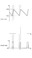
- FIG. 2 is a timing chart for explaining an anode pulsating operation during steady operation of the fuel cell system 1.
- the controller 60 calculates the target output of the fuel cell stack 10 according to the traveling condition of the vehicle, and the upper limit value and the lower limit value of the anode gas supply pressure (anode pressure) based on the target output. Set Then, the anode pressure is periodically increased and decreased between the set upper limit value and the lower limit value of the anode pressure.
- the pressure regulating valve 23 is opened to an opening degree at which at least the anode pressure can be increased to the upper limit value.
- the anode gas is supplied from the high pressure tank 21 to the fuel cell stack 10, and the anode off gas is discharged to the buffer tank 26.
- the pressure regulating valve 23 When the anode pressure reaches the upper limit value at time t2, the pressure regulating valve 23 is fully closed as shown in FIG. 2B, and the supply of the anode gas from the high pressure tank 21 to the fuel cell stack 10 is stopped.
- the anode pressure is reduced by the amount of consumption of the anode gas.
- the pressure in the buffer tank 26 temporarily becomes higher than the pressure in the anode gas flow path of the fuel cell stack 10. And anode off gas back flow.
- the anode gas left in the anode gas flow path of the fuel cell stack 10 and the anode gas in the anode off gas backflowing from the buffer tank 26 are consumed over time.
- the pressure regulating valve 23 When the anode pressure reaches the lower limit value at time t3, the pressure regulating valve 23 is opened in the same manner as at time t1. Then, when the anode pressure reaches the upper limit value again at time t4, the pressure regulating valve 23 is fully closed. By periodically opening and closing the pressure control valve 23 as described above, the anode pulsation operation is performed, and the anode gas in the anode off gas is reused.
- FIG. 3 is an exploded view of the fuel cell stack 10.
- 4A is a front view of the membrane electrode assembly (MEA) 110
- FIG. 4B is a front view of the anode separator 120
- FIG. 4C is a front view of the cathode separator 130.
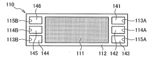
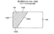
- FIG. 5 is an enlarged view of the vicinity of the discharge-side internal manifolds 144 to 146 of the MEA 110.
- the fuel cell stack 10 is configured by laminating a plurality of fuel cells 100 including the MEA 110, an anode separator 120, and a cathode separator 130.
- the fuel cell 100 has a structure in which the anode separator 120 is disposed on one side of the MEA 110 and the cathode separator 130 is disposed on the other side.
- the frame portion 112 of the MEA 110 is a frame member made of a synthetic resin or the like, and is integrally formed on the outer edge of the laminated body 111.
- An anode gas supply hole 113A, a cooling water supply hole 114A, and a cathode gas supply hole 115A are formed in order from the top in the frame portion 112 on one end side (right side in the drawing).
- a cathode gas discharge hole 115B, a cooling water discharge hole 114B, and an anode gas discharge hole 113B are formed in order from the top in the frame portion 112 on the other end side (left side in the drawing).
- the anode separator 120 is a plate-like member formed of a conductive material such as metal.
- the anode separator 120 forms an anode gas flow channel 121 for flowing anode gas on the surface on the MEA 110 side, and forms a cooling water flow channel (not shown) for flowing cooling water on the surface on the opposite side to the MEA 110 side.
- An anode gas supply hole 123A, a cooling water supply hole 124A, and a cathode gas supply hole 125A are formed in this order from the top on one end side of the anode separator 120. Further, on the other end side of the anode separator 120, a cathode gas discharge hole 125B, a cooling water discharge hole 124B, and an anode gas discharge hole 123B are formed sequentially from the top.
- the cathode separator 130 is a plate-like member formed of a conductive material such as metal.
- the cathode separator 130 forms a cathode gas flow channel 131 for flowing the cathode gas on the surface on the MEA 110 side, and forms a cooling water flow channel (not shown) for flowing the cooling water on the surface on the opposite side to the MEA 110 side.
- An anode gas supply hole 133A, a cooling water supply hole 134A, and a cathode gas supply hole 135A are formed in this order from the top on one end side of the cathode separator 130. Further, on the other end side of the cathode separator 130, a cathode gas discharge hole 135B, a cooling water discharge hole 134B, and an anode gas discharge hole 133B are formed sequentially from the top.
- the anode gas supply holes 113A, 123A, 133A are connected in the stacking direction to form an internal manifold 141 for anode gas supply
- the cooling water supply holes 114A, 124A and 134A are continuous in the stacking direction to form an internal manifold 142 for cooling water supply
- cathode gas supply holes 115A, 125A and 135A are continuous in the stacking direction to form an internal manifold 143 for cathode gas supply.
- anode gas discharge holes 113B, 123B and 133B are continuous in the stacking direction to form an internal manifold 144 for discharging anode gas
- cooling water discharge holes 114B, 124B and 134B are continuous in the stacking direction to discharge cooling water.
- the inner manifold 145 is formed, and the cathode gas discharge holes 115B, 125B, and 135B are connected in the stacking direction to form an inner manifold 146 for discharging the cathode gas.
- seal members 116 are provided on the front and back surfaces of the MEA 110 so as to surround the outer edge of the MEA 110 and the respective internal manifolds 141 to 146.
- An adhesive 117 for bonding the MEA 110 to the anode separator 120 and the cathode separator 130 is filled in the region between the seal member 116 and each of the inner manifolds 141-146.
- the seal member 116 and the adhesive agent 117 are provided except for a portion where gas or the like enters and leaves the respective internal manifolds 141 to 146.
- the fuel cell stack 10 is configured by the seal member 116 and the adhesive 117 so that the gas and the cooling water flowing through the respective internal manifolds 141 to 146 do not leak.
- the internal manifolds 141 to 146 extending in the stacking direction (horizontal) of the fuel cell 100 are formed in the fuel cell stack 10, and the anode gas is supplied to each fuel cell 100 via the internal manifolds 141 to 143.
- the cathode gas and the cooling water are supplied, and the anode gas, the cathode gas and the cooling water are discharged from each fuel cell 100 through the internal manifolds 144 to 146.
- generated water generated at the time of power generation or the like flows into the discharge-side internal manifolds 144 and 146 that discharge the anode gas and the cathode gas to the outside.
- generated water tends to be accumulated in the exhaust-side internal manifold 144 that discharges the anode gas to the outside.
- the power generation performance of the fuel cell stack 10 may be deteriorated due to a decrease in the anode gas flow rate or the like.
- the extending member 150 extended in the stacking direction is disposed in the discharge-side internal manifold 144 for discharging the anode gas to the outside, and the discharge performance of the generated water is obtained. It is raising.
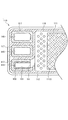
- FIG. 5 is an enlarged view of the vicinity of the discharge-side internal manifolds 144 to 146 of the MEA 110.
- FIG. 6 is a perspective view of the extending member 150.
- the extending member 150 is a cylindrical member having a substantially U-shaped cross section, and is formed of an insulating resin material.
- the extending member 150 may be formed of a metal material, in which case the surface of the member is coated.
- a gas inlet port 151 is formed on the side of the extending member 150 located on the inner side in the width direction of the fuel cell stack 10. Further, at one end of the extending member 150 in the longitudinal direction, a discharge port 152 for discharging the gas flowing from the inflow port 151 to the outside of the fuel cell stack 10 is formed.
- the inner wall surface of the extending member 150 is formed flat so as not to obstruct the flow of gas or generated water in the fuel cell 100 in the stacking direction.
- the extending member 150 is disposed in the inner manifold 144 in a state where the outer wall surface of the extending member 150 is in contact with the inner wall surface of the inner manifold 144 for discharging the anode gas. Since the extending member 150 is disposed in contact with the inner wall surface of the internal manifold 144 as described above, the extending member 150 functions as a member for positioning the fuel cells 100 when the fuel cell stack 10 is assembled. In the state of being installed in the internal manifold 144, the inner wall bottom surface 153 of the extending member 150 is set higher than the lower end position 111A of the laminate 111 (active area) of the MEA 110 (see FIG. 5). ).
- a portion of the generated water generated at the time of power generation and the anode gas not used for power generation flow into the inside of the extension member 150 disposed in the internal manifold 144 via the inlet 151. Since the extending member 150 is a member extended in the stacking direction of the fuel cell 100, the generated water flowing into the inside of the extending member 150 smoothly flows downstream with the flow of the anode gas, and is discharged. The fuel is discharged to the outside of the fuel cell stack 10 through the outlet 152.
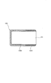
- the extending member 150 provided in the internal manifold 144 also functions as a support member for supporting the stacked fuel cells 100, the fuel cell stack 10 is bent by its own weight as shown by a broken line in FIG. Can be prevented.
- the fuel cell stack 10 includes the extending member 150 extended in the stacking direction of the fuel cell 100 in a state of being in contact with the inner wall surface of the internal manifold 144 for discharging the anode gas. Flows smoothly along the inner wall surface of the extending member 150. Thus, the generated water can be easily discharged through the extending member 150, and the discharge performance of the generated water in the internal manifold 144 can be enhanced. Further, by arranging the extending member 150 in contact with the inner wall surface of the internal manifold 144, it becomes possible to position each fuel cell 100 when assembling the fuel cell stack 10.
- the extending member 150 is formed as a cylindrical member in contact with the inner wall upper surface, inner wall side surface and inner wall bottom surface of the inner manifold 144, but the inner wall upper surface, inner wall side surface and inner wall of the inner manifold 144 You may form as a rod-shaped member (rod-shaped member) contact
- the extending member 150 according to the second embodiment is different from the fuel cell stack according to the first embodiment in that the extending member 150 is a water repellent member.
- the extending member 150 of the second embodiment is formed of a highly water-repellent resin material such as polytetrafluoroethylene (PTFE).
- PTFE polytetrafluoroethylene
- the extending member 150 is coated with high water repellency, the fluidity of the generated water is deteriorated when the coating is peeled off due to deterioration over time, etc., but in the present embodiment, the extending member 150 itself is made of PTFE. Since it forms, even if it uses it for a long period of time, there is almost no fall of the water repellency of extension member 150.
- the extending member 150 according to the third embodiment is different from the fuel cell stack according to the first embodiment in that the extending member 150 is formed of a hydrophilic member.
- the extending member 150 of the third embodiment is formed of a highly hydrophilic resin material such as polyethylene terephthalate (PET) or polyphenylene sulfide (PPS). In view of heat resistance, polyphenylene sulfide (PPS) is more preferable.
- PET polyethylene terephthalate
- PPS polyphenylene sulfide
- the amount of generated water flowing into the internal manifold 144 for discharging anode gas increases, and the generated water can be discharged efficiently.
- the surface of the extending member 150 is coated with high hydrophilicity, the drawability of generated water is deteriorated when the coating is peeled off due to deterioration over time, etc., but in the present embodiment, the extending member 150 itself is Thus, the hydrophilic performance of the extending member 150 is hardly deteriorated even when used for a long time.
- the extending member 150 according to the fourth embodiment is different from the fuel cell stack according to the first embodiment in that the extending member 150 is composed of a hydrophilic member and a water repellent member.
- FIG. 8 is a longitudinal sectional view of the extending member 150 according to the fourth embodiment.
- the inner portion 150A near the center (closer to the inlet 151) of the fuel cell 100 is made of PET, which is more hydrophilic than the member constituting the internal manifold 144,
- the outer portion 150 ⁇ / b> B is made of PTFE, which is more water repellent than the members constituting the inner manifold 144.
- the inner portion 150A of the extension member 150 highly hydrophilic, generated water in the vicinity of the inflow port 151 is easily drawn into the inside of the extension member 150. Further, by making the outer portion 150B of the extending member 150 highly water-repellent, the drawn-in generated water can be made to flow smoothly in the fuel cell 100 stacking direction. This makes it possible to enhance the discharge performance of the generated water in the internal manifold 144.
- the extending member 150 according to the fifth embodiment is different from the fuel cell stack according to the first embodiment in that the extending member 150 is composed of a hydrophilic member and a water repellent member.
- FIG. 9 is a top view of the extending member 150 according to the fifth embodiment.
- the upstream portion 150C in the anode gas discharge direction is made of PET or PPS, which is more hydrophilic than the member constituting the internal manifold 144, and is closer to the discharge port 152.
- the downstream portion 150D is made of PTFE, which is more water repellent than the member constituting the internal manifold 144.
- the product water drawn in on the upstream side can be made to flow smoothly to the downstream side. It is possible to enhance the discharge performance of generated water in the internal manifold 144.
- the upstream side portion 150C is made highly hydrophilic and the downstream side portion 150D is made highly water-repellent, so that from the upstream to the downstream, the hydrophilicity gradually changes to high water-repellent It may be configured.
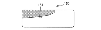
- an extending member 150 according to a sixth embodiment of the present invention will be described.
- the extending member 150 according to the sixth embodiment differs in the inner structure from the fuel cell stacks according to the first to fifth embodiments.
- FIG. 10 is a longitudinal sectional view of the extending member 150 according to the sixth embodiment.
- the inner wall upper surface 154 of the extending member 150 is formed as an inclined surface.
- the inner wall upper surface 154 is configured to incline downward from the inside to the outside in a direction (width direction of the fuel cell stack 10) orthogonal to the stacking direction of the fuel cells 100.
- the generated water adhering to the inner wall upper surface 154 is guided to the inner back side of the extending member 150 and flows back from the inflow port 151 to the outside. It can prevent.
- the extending member 150 includes a protrusion 153A that protrudes upward from the inner wall bottom surface 153.
- the projecting portion 153 ⁇ / b> A is extended along the stacking direction of the fuel cell 100 at an inner portion closer to the inflow port 151.
- the protrusion 153 ⁇ / b> A functions as an embankment that prevents the generated water flowing on the inner wall bottom surface 153 from flowing out to the outside of the extension member 150.
- the extending member 150 of the sixth embodiment described above is configured such that the inner wall upper surface 154 is inclined and the inner wall bottom surface 153 is provided with the projecting portion 153A, the generated water once flowing into the inside of the extending member 150 is a fuel Backflow to the battery 100 side can be prevented, and the generated water can be stably discharged to the outside of the fuel cell stack 10.
- the inner wall upper surface 154 of the extending member 150 is an inclined surface which is linearly inclined downward toward the outside, the present invention is not limited to this.
- the inner wall upper surface 154 of the extension member 150 may have a configuration in which the generated water adhering to the inner wall surface 154 hardly has a backflow toward the fuel cell 100 as shown in FIGS. 11A to 11E.
- the inner wall upper surface 154 of the extension member 150 may be an inclined surface in which the inner portion is inclined downward and the outer portion may be a horizontal surface.
- the inner wall upper surface 154 of the extending member 150 is an inclined surface which is inclined downward from the inner side in a convex state as shown in FIG. 11B or as shown in FIG. 11C from an inner side in a convex state. It may be an inclined surface inclined downward to the outside.
- the inner wall upper surface 154 of the extending member 150 has a wavy shape in which smooth asperities are continuously formed from the inside to the outside as shown in FIG. 11D, or as shown in FIG. It may be formed into a sawtooth shape.
- the projecting portion 153A of the extending member 150 is a relatively wide member as shown in FIG. 10, but the present invention is not limited to this.
- the projecting portion 153 ⁇ / b> A may be an upright wall which is erected from the inner wall bottom surface 153 close to the inflow port 151 and extends in the stacking direction of the fuel cell 100. Even with such a rising wall, it is possible to prevent the generated water flowing on the inner wall bottom surface 153 from flowing back to the fuel cell 100 side.
- an extension member 150 according to a seventh embodiment of the present invention will be described.
- the extending member 150 according to the seventh embodiment is different in shape from the extending member 150 of the first to sixth embodiments.
- FIG. 13 is a longitudinal sectional view of the extending member 150 according to the seventh embodiment.
- the extending member 150 is a rod-like member having a substantially trapezoidal cross section, and is formed of a highly hydrophilic resin material.
- an upper side surface (hereinafter referred to as “upper side surface”) 150E, an outer side (left side in the drawing) side surface (hereinafter referred to as “outer side surface”) 150F and a lower side surface (hereinafter referred to Each of the lower side surfaces 150G is disposed in the inner manifold 144 so as to abut on the inner wall upper surface, inner wall outer surface and inner wall bottom surface of the inner manifold 144.
- the side surface 150H on the inner side (right side in the figure, ie, the side of the laminated body 111) 150H of the extending member 150 has an acute angle ⁇ between the inner side surface 150H and the bottom surface of the inner manifold 144. To be inclined downward from the inside to the outside.
- FIG. 14 is a view for explaining the effect of the fuel cell stack 10 according to the seventh embodiment.
- the extending member 150 is formed of a member having a higher hydrophilicity than the member forming the internal manifold 144, and the angle ⁇ between the inner side surface 150H and the bottom surface of the inner wall of the internal manifold 144 is acute.
- the inner side surface 150H was inclined.
- the generated water attached to the upper surface of the inner wall of the internal manifold 144 can be drawn into the inner side surface 150H of the extending member 150 and further drawn into the acute angle region shown by the broken line in the drawing using the inclination of the inner side surface 150H. it can.
- the highly hydrophilic member has a characteristic of drawing generated water in a narrow area as compared with the surrounding. Therefore, when the extending member 150 is formed of a highly hydrophilic member, generated water is drawn into an acute angle area which is a narrow area as compared with the surrounding area. As a result, in addition to the generated water adhering to the upper surface of the inner wall of the internal manifold 144, the generated water adhering to the bottom surface of the inner wall of the internal manifold 144 can also be drawn into the acute angle region.
- extension member 150 a rod-like member, the volume in the internal manifold 144 is reduced, so that the flow velocity of the anode off gas flowing in the internal manifold can be increased.
- the generated water drawn into the acute angle region can be moved more smoothly along the inner side surface 150H in the stacking direction.
- the extending member 150 is a rod-like member, and the extending member 150 is disposed in the inner manifold 144 such that each of the upper side surface 150E and the lower side surface 150G abuts on the inner wall upper surface and the inner wall bottom surface of the inner manifold 144. .
- the function as a supporting member for supporting the stacked fuel cell 100 is further strengthened, as compared with the case where the extending member 150 is a cylindrical member having a substantially U-shaped cross section as in the first embodiment,
- the fuel cell stack 10 can be further prevented from being flexed by its own weight as shown by a broken line in FIG.
- an extending member 150 according to an eighth embodiment of the present invention will be described.
- the eighth embodiment is different from the seventh embodiment in that a shock absorbing material 160 is provided between the extending member 150 and the internal manifold 144.
- FIG. 15 is a longitudinal sectional view of the extension member 150 and the shock absorbing material 160 according to the eighth embodiment.
- the shock absorbing material 160 is a cylindrical member having a substantially U-shaped cross section, and is formed of an elastic body such as a synthetic rubber containing silicone rubber.
- the shock absorbing material 160 is in contact with the upper side surface 150E, the outer side surface 150F and the lower side surface 150G of the extending member 150, and the outer peripheral surface is the upper inner wall surface, the inner wall outer surface and the inner wall of the inner manifold. It is disposed in the inner manifold 144 to abut the bottom surface.
- the internal temperature of the fuel cell stack 10 rises.
- the member constituting the internal manifold 144 and the member constituting the extending member 150 are different members, and the member constituting the extending member 150 is thermally expanded more than the member constituting the internal manifold 144 The rate is large. Therefore, when the extension member 150 is expanded, a load is input to the internal manifold 144 from the extension member 150, which causes the durability of the fuel cell stack 10 to be reduced.
- the shock absorbing material 160 between the extending member 150 and the internal manifold 144 as in the present embodiment, the load input from the extending member 150 to the internal manifold 144 can be reduced.
- the durability of the battery stack 10 can be improved.
- the extension member 150 and the shock absorbing material 160 are separately formed, but may be integrally formed. Moreover, although the shock absorbing material 160 was provided in the whole region of the upper side 150E, the outer side 150F, and the lower side 150G of the extending member 150, it is good also as providing only in the one part area
- the ninth embodiment Next, an extending member 150 according to a ninth embodiment of the present invention will be described.
- the ninth embodiment is different from the seventh embodiment in that a sliding member 170 is provided between the extending member 150 and the internal manifold 144.
- FIG. 16 is a longitudinal sectional view of the extending member 150 and the sliding member 170 according to the ninth embodiment.
- the sliding member 170 is a cylindrical member having a substantially U-shaped cross section, and is formed of a resin member containing polyimide, etc., as long as it has a relatively low friction coefficient. It is not limited to this.
- the sliding member 170 has its outer peripheral surface in contact with the upper side surface 150E, the outer side surface 150F and the lower side surface 150G of the extending member 150, and the outer peripheral surface thereof is the inner wall upper surface, inner wall outer surface and inner wall of the internal manifold. It is disposed in the inner manifold 144 to abut the bottom surface.
- the slide member 170 on the outer peripheral surface of the extending member 150, the assemblability when inserting the extending member 150 into the internal manifold 150 can be improved. In addition, it is possible to suppress the component wear due to the sliding between the extension member 150 and the inner wall surface of the internal manifold 144 at the time of assembly, and to improve the durability of the fuel cell stack 10.
- the extending member 150 and the sliding member 170 are individually formed, they may be integrally formed. Further, although the slide member 170 is provided on the entire area of the upper side surface 150E, the outer side surface 150F, and the lower side surface 150G of the extension member 150, the slide member 170 may be provided only in a partial region thereof.
- an extending member 150 according to a tenth embodiment of the present invention will be described.
- the tenth embodiment is different from the seventh embodiment in that the cross-sectional area of the longitudinal cross section of the extending member 150 is made smaller toward the anode gas outlet of the fuel cell stack 10.
- FIG. 17 is a schematic cross-sectional view of a fuel cell stack 10 provided with the extending member 150 according to the present embodiment.
- 18A shows a longitudinal sectional view of the extending member 150 at one end of the fuel cell stack 10
- FIG. 18B shows a longitudinal sectional view of the extending member 150 at the other end of the fuel cell stack 10. As shown in FIG.
- an anode gas inlet and an anode gas outlet are formed on one end side of the fuel stack 10.
- the flow velocity of the anode off gas flowing through the internal manifold 144 is faster on one end side (the side on which the anode gas outlet portion is formed) than on the other end side of the fuel cell stack 10. .
- the extending member 150 is formed such that the cross-sectional area of the longitudinal cross section of the extending member 150 becomes smaller toward the anode gas outlet of the fuel cell stack 10. did.
- the extending member 150 according to the present embodiment is formed such that the space through which the anode off gas flows in the internal manifold 144 becomes larger toward the anode gas outlet of the fuel cell stack 10.
- the flow rate of the anode off gas flowing in the internal manifold 144 can be made uniform, so that the drainage performance can be improved while the flow rate of the anode gas distributed to each fuel cell 100 can be made uniform.
- an extending member 150 according to an eleventh embodiment of the present invention will be described.
- the eleventh embodiment differs from the seventh embodiment in that a protrusion 150H is provided at the end of the extending member 150 to prevent the extending member 150 from shifting in the direction perpendicular to the stacking direction.
- FIG. 20 is a schematic cross-sectional view of the fuel cell stack 10.
- FIG. 21 is a cross-sectional view of the extension member 150 taken along the line XX-XX in FIG.
- the fuel cell stack 10 is provided with a plate 13 for holding the stacked fuel cells at both end portions in the stacking direction.
- the plate 13 is also present in the above-described embodiments, the illustration is omitted.
- a communication hole 131 communicating with the internal manifold 144 and the anode gas outlet portion is formed in the plate 13. And in this embodiment, as shown in FIG. 20, the extending member 150 is extended to the communication hole 131 of the plate 13, and further, as shown in FIGS. 20 and 21, inside the communication hole 131, the inside of the communication hole 131. A protrusion 150H that abuts the side surface is provided on the extending member 150.
- the extending member 150 is installed in the internal manifold 144 for discharging anode gas, but the extending member 150 is installed in the internal manifold 146 for discharging cathode gas in the same manner. It is also good.
- the extension member 150 is installed in the internal manifolds 144 and 146, not only the discharge performance of generated water can be enhanced in both internal manifolds 144 and 146, but also the alignment accuracy of the fuel cell 100 can be enhanced. It becomes.
- the fuel cell stack 10 including the extending member 150 is applied to the non-anode fuel cell system, but the present invention is not limited to this.
- the fuel cell stack 10 including the extending member 150 may be applied to an anode circulating fuel cell system capable of circulating the anode off gas to the anode gas supply passage 22.
- the extending member 150 is a single rod-like member, but as shown in FIG. 22, even if it is divided into a number smaller than the total number of fuel cells 100 for improvement of assemblability. good.
Abstract
Description
カソード電極: 4H++4e-+O2 → 2H2O ・・・(2)
図1は、本発明の第1実施形態による燃料電池スタック10を備える燃料電池システム1の概略構成図である。
次に、本発明の第2実施形態による延設部材150について説明する。第2実施形態による延設部材150は撥水性部材によって構成されている点で第1実施形態の燃料電池スタックと相違する。
次に、本発明の第3実施形態による延設部材150について説明する。第3実施形態による延設部材150は親水性部材によって構成されている点で第1実施形態の燃料電池スタックと相違する。
次に、本発明の第4実施形態による延設部材150について説明する。第4実施形態による延設部材150は親水性部材及び撥水性部材によって構成されている点で第1実施形態の燃料電池スタックと相違する。
次に、本発明の第5実施形態による延設部材150について説明する。第5実施形態による延設部材150は親水性部材及び撥水性部材によって構成されている点で第1実施形態の燃料電池スタックと相違する。
次に、本発明の第6実施形態による延設部材150について説明する。第6実施形態による延設部材150は内側構造において第1~第5実施形態の燃料電池スタックと相違する。
次に、本発明の第7実施形態による延設部材150について説明する。第7実施形態による延設部材150は、その形状が第1~第6実施形態の延設部材150と相違する。
次に、本発明の第8実施形態による延設部材150について説明する。第8実施形態では、延設部材150と内部マニホールド144との間に緩衝材160を設けた点で第7実施形態と相違する。
次に、本発明の第9実施形態による延設部材150について説明する。第9実施形態では、延設部材150と内部マニホールド144との間に滑り部材170を設けた点で第7実施形態と相違する。
次に、本発明の第10実施形態による延設部材150について説明する。第10実施形態では、延設部材150の縦断面の断面積を、燃料電池スタック10のアノードガス出口部ほど小さくする点で第7実施形態と相違する。
次に、本発明の第11実施形態による延設部材150について説明する。第11実施形態では、延設部材150の端部に、延設部材150の積層方向と直行する方向へのずれを防止する突起部150Hを設けた点で第7実施形態と相違する。
Claims (17)
- 複数の燃料電池が積層されることで積層方向に延設され、前記燃料電池で使用されたガスを外部に排出する内部マニホールドを備える燃料電池スタックにおいて、
前記内部マニホールドの内壁面に接した状態で積層方向に延設される延設部材を備える燃料電池スタック。 - 前記延設部材は、前記内部マニホールド内に前記燃料電池からのガスが流入する側の反対側に設けられる棒状部材である請求項1に記載の燃料電池スタック。
- 前記延設部材は、前記内部マニホールドの内壁底面とのなす角が鋭角となる傾斜面を備える請求項2に記載の燃料電池スタック。
- 前記延設部材は、前記内部マニホールドを構成する部材よりも親水性が高い親水部材から構成される請求項2又は請求項3に記載の燃料電池スタック。
- 前記延設部材は、前記内部マニホールドの内壁面と接する部分に緩衝材を有する請求項2から請求項4までのいずれか1つに記載の燃料電池スタック。
- 前記延設部材は、前記内部マニホールドの内壁面と接する部分に低摩擦材を有する請求項2から請求項4までのいずれか1つに記載の燃料電池スタック。
- 前記延設部材は、前記内部マニホールド内に占める前記延設部材の割合が、前記内部マニホールドの出口に近いほど少なくなるように構成される請求項2から請求項6までのいずれか1つに記載の燃料電池スタック。
- 前記燃料電池スタックは、積層した前記燃料電池の積層方向外側に設けられ、前記内部マニホールドと連通する連通孔を有するプレートを備え、
前記延設部材は、前記プレートの連通孔まで延設されると共に、前記延設部材が積層方向と直交する方向にずれるのを抑制するずれ抑制部を前記プレートの連通孔内に備える、
請求項1から請求項7までのいずれか1つに記載の燃料電池スタック。 - 前記延設部材は、前記燃料電池からのガスが流入可能な流入部を有する筒状部材である請求項1に記載の燃料電池スタック。
- 前記延設部材は、前記内部マニホールドを構成する部材よりも撥水性が高い撥水部材から構成される請求項1又は請求項9に記載の燃料電池スタック。
- 前記延設部材は、前記内部マニホールドを構成する部材よりも親水性が高い親水部材から構成される請求項1又は請求項9に記載の燃料電池スタック。
- 前記延設部材は、燃料電池中央寄りの内側部分が前記内部マニホールドを構成する部材よりも親水性の高い親水部材によって構成され、外側部分が前記内部マニホールドを構成する部材よりも撥水性の高い撥水部材によって構成される請求項1又は請求項9に記載の燃料電池スタック。
- 前記延設部材は、ガス排出方向における上流部分が前記内部マニホールドを構成する部材よりも親水性の高い親水部材によって構成され、下流部分が前記内部マニホールドを構成する部材よりも撥水性の高い撥水部材によって構成される請求項1又は請求項9に記載の燃料電池スタック。
- 前記延設部材の内壁上面は、前記燃料電池側への生成水の逆流を防止するように、傾斜面として形成される請求項1及び請求項9から請求項13のいずれか一つに記載の燃料電池スタック。
- 前記延設部材の内壁底面には、前記燃料電池側への生成水の逆流を防止するように、上方に突出する突出部が形成されることを特徴とする請求項1及び請求項9から請求項14のいずれか一つに記載の燃料電池スタック。
- 前記延設部材は、アノードガスを外部に排出する内部マニホールド及びカソードガスを外部に排出する内部マニホールド内にそれぞれ設けられる請求項1から請求項15のいずれか一つに記載の燃料電池スタック。
- 請求項1から請求項16のいずれか一つに記載の燃料電池スタックを備える燃料電池システムにおいて、
前記燃料電池スタックに供給するアノードガスの圧力を制御する制御弁と、
前記燃料電池スタックから排出されるアノードオフガスを蓄えるバッファタンクと、
前記制御弁を周期的に開閉してアノードガスの供給圧力を増減圧させることで、アノード脈動運転を実行する制御部と、を備える燃料電池システム。
Priority Applications (5)
| Application Number | Priority Date | Filing Date | Title |
|---|---|---|---|
| CN201380008529.1A CN104106167B (zh) | 2012-02-09 | 2013-02-05 | 燃料电池堆和燃料电池系统 |
| EP13746642.1A EP2814101B1 (en) | 2012-02-09 | 2013-02-05 | Fuel cell stack and fuel cell system |
| JP2013557520A JP5850067B2 (ja) | 2012-02-09 | 2013-02-05 | 燃料電池スタック及び燃料電池システム |
| CA2864217A CA2864217C (en) | 2012-02-09 | 2013-02-05 | Fuel cell stack and fuel cell system |
| US14/377,740 US10522866B2 (en) | 2012-02-09 | 2013-02-05 | Fuel cell stack and fuel cell system |
Applications Claiming Priority (4)
| Application Number | Priority Date | Filing Date | Title |
|---|---|---|---|
| JP2012-026272 | 2012-02-09 | ||
| JP2012026272 | 2012-02-09 | ||
| JP2012174187 | 2012-08-06 | ||
| JP2012-174187 | 2012-08-06 |
Publications (1)
| Publication Number | Publication Date |
|---|---|
| WO2013118719A1 true WO2013118719A1 (ja) | 2013-08-15 |
Family
ID=48947482
Family Applications (1)
| Application Number | Title | Priority Date | Filing Date |
|---|---|---|---|
| PCT/JP2013/052604 WO2013118719A1 (ja) | 2012-02-09 | 2013-02-05 | 燃料電池スタック及び燃料電池システム |
Country Status (6)
| Country | Link |
|---|---|
| US (1) | US10522866B2 (ja) |
| EP (1) | EP2814101B1 (ja) |
| JP (1) | JP5850067B2 (ja) |
| CN (1) | CN104106167B (ja) |
| CA (1) | CA2864217C (ja) |
| WO (1) | WO2013118719A1 (ja) |
Cited By (3)
| Publication number | Priority date | Publication date | Assignee | Title |
|---|---|---|---|---|
| CN106104114A (zh) * | 2014-03-07 | 2016-11-09 | 日产自动车株式会社 | 流体控制阀 |
| JP2017117543A (ja) * | 2015-12-21 | 2017-06-29 | トヨタ自動車株式会社 | 燃料電池及び燃料電池システム |
| JP7380431B2 (ja) | 2020-06-02 | 2023-11-15 | トヨタ自動車株式会社 | 燃料電池システム |
Families Citing this family (6)
| Publication number | Priority date | Publication date | Assignee | Title |
|---|---|---|---|---|
| EP3364674B1 (en) * | 2015-11-06 | 2019-10-09 | Huawei Technologies Co., Ltd. | Voice roaming method, mobility management network element, and access network element |
| DE102017202705A1 (de) * | 2017-02-20 | 2018-08-23 | Bayerische Motoren Werke Aktiengesellschaft | Brennstoffzellenstapel mit Verteilungselement im Medienkanal sowie Herstellverfahren |
| JP6809401B2 (ja) * | 2017-07-12 | 2021-01-06 | トヨタ自動車株式会社 | 燃料電池システム |
| DE102020202061A1 (de) * | 2020-02-19 | 2021-08-19 | Robert Bosch Gesellschaft mit beschränkter Haftung | Oberflächenstruktur zum Abscheiden von Wasser in einem Brennstoffzellensystem |
| DE202020106459U1 (de) | 2020-11-11 | 2022-02-16 | Reinz-Dichtungs-Gmbh | Anordnung für ein elektrochemisches System, Stapel sowie elektrochemisches System |
| DE102021209853A1 (de) | 2021-09-07 | 2023-03-09 | Robert Bosch Gesellschaft mit beschränkter Haftung | Brennstoffzellensystem mit Strömungsfolie und Kraftfahrzeug mit Brennstoffzellensystem |
Citations (5)
| Publication number | Priority date | Publication date | Assignee | Title |
|---|---|---|---|---|
| JP2000149977A (ja) * | 1998-11-06 | 2000-05-30 | Honda Motor Co Ltd | 燃料電池スタック |
| JP2001118596A (ja) * | 1999-10-19 | 2001-04-27 | Honda Motor Co Ltd | 燃料電池スタック |
| JP2005209526A (ja) * | 2004-01-23 | 2005-08-04 | Fuji Electric Holdings Co Ltd | 固体高分子形燃料電池 |
| JP2006066131A (ja) | 2004-08-25 | 2006-03-09 | Honda Motor Co Ltd | 燃料電池 |
| JP2006202524A (ja) * | 2005-01-18 | 2006-08-03 | Nissan Motor Co Ltd | 燃料電池スタックのマニホールド構造 |
Family Cites Families (8)
| Publication number | Priority date | Publication date | Assignee | Title |
|---|---|---|---|---|
| US6936369B1 (en) | 1999-10-19 | 2005-08-30 | Honda Giken Kogyo Kabushiki Kaisha | Fuel cell stack |
| US20040023090A1 (en) * | 2002-03-30 | 2004-02-05 | Pearson Kenneth E. | Fuel cell system |
| JP2006147503A (ja) * | 2004-11-25 | 2006-06-08 | Honda Motor Co Ltd | 燃料電池スタック |
| KR100911988B1 (ko) * | 2007-11-14 | 2009-08-13 | 삼성에스디아이 주식회사 | 연료전지 스택 |
| JP5877492B2 (ja) * | 2010-07-21 | 2016-03-08 | 日産自動車株式会社 | 燃料電池システム及びその運転方法 |
| KR101209684B1 (ko) * | 2010-11-17 | 2012-12-10 | 기아자동차주식회사 | 분배 가이드를 갖는 스택 매니폴드 인서트 및 이를 포함하는 연료전지 스택 |
| CA2817819C (en) | 2010-12-17 | 2015-06-09 | Nissan Motor Co., Ltd. | Fuel cell with water inflow preventing portion |
| KR101272594B1 (ko) * | 2011-07-12 | 2013-06-11 | 기아자동차주식회사 | 연료전지 스택용 매니폴드 블록 |
-
2013
- 2013-02-05 EP EP13746642.1A patent/EP2814101B1/en active Active
- 2013-02-05 WO PCT/JP2013/052604 patent/WO2013118719A1/ja active Application Filing
- 2013-02-05 JP JP2013557520A patent/JP5850067B2/ja active Active
- 2013-02-05 US US14/377,740 patent/US10522866B2/en active Active
- 2013-02-05 CN CN201380008529.1A patent/CN104106167B/zh active Active
- 2013-02-05 CA CA2864217A patent/CA2864217C/en active Active
Patent Citations (5)
| Publication number | Priority date | Publication date | Assignee | Title |
|---|---|---|---|---|
| JP2000149977A (ja) * | 1998-11-06 | 2000-05-30 | Honda Motor Co Ltd | 燃料電池スタック |
| JP2001118596A (ja) * | 1999-10-19 | 2001-04-27 | Honda Motor Co Ltd | 燃料電池スタック |
| JP2005209526A (ja) * | 2004-01-23 | 2005-08-04 | Fuji Electric Holdings Co Ltd | 固体高分子形燃料電池 |
| JP2006066131A (ja) | 2004-08-25 | 2006-03-09 | Honda Motor Co Ltd | 燃料電池 |
| JP2006202524A (ja) * | 2005-01-18 | 2006-08-03 | Nissan Motor Co Ltd | 燃料電池スタックのマニホールド構造 |
Cited By (6)
| Publication number | Priority date | Publication date | Assignee | Title |
|---|---|---|---|---|
| CN106104114A (zh) * | 2014-03-07 | 2016-11-09 | 日产自动车株式会社 | 流体控制阀 |
| EP3116056A1 (en) * | 2014-03-07 | 2017-01-11 | Nissan Motor Co., Ltd. | Fluid control valve |
| EP3116056A4 (en) * | 2014-03-07 | 2017-03-29 | Nissan Motor Co., Ltd | Fluid control valve |
| US10559837B2 (en) | 2014-03-07 | 2020-02-11 | Nissan Motor Co., Ltd. | Fluid control valve |
| JP2017117543A (ja) * | 2015-12-21 | 2017-06-29 | トヨタ自動車株式会社 | 燃料電池及び燃料電池システム |
| JP7380431B2 (ja) | 2020-06-02 | 2023-11-15 | トヨタ自動車株式会社 | 燃料電池システム |
Also Published As
| Publication number | Publication date |
|---|---|
| CN104106167A (zh) | 2014-10-15 |
| JPWO2013118719A1 (ja) | 2015-05-11 |
| CA2864217A1 (en) | 2013-08-15 |
| US10522866B2 (en) | 2019-12-31 |
| US20160013509A1 (en) | 2016-01-14 |
| JP5850067B2 (ja) | 2016-02-03 |
| CN104106167B (zh) | 2016-08-31 |
| EP2814101A4 (en) | 2015-09-23 |
| CA2864217C (en) | 2016-11-08 |
| EP2814101A1 (en) | 2014-12-17 |
| EP2814101B1 (en) | 2019-07-31 |
Similar Documents
| Publication | Publication Date | Title |
|---|---|---|
| WO2013118719A1 (ja) | 燃料電池スタック及び燃料電池システム | |
| US8153321B2 (en) | Fuel cell system having switching fuel flow | |
| WO2015170413A1 (ja) | 燃料電池システム及び燃料電池システムの制御方法 | |
| JP5204896B2 (ja) | Pem燃料電池システムの出力電圧を制限する方法 | |
| CN111276717A (zh) | 燃料电池系统 | |
| JP7155550B2 (ja) | 燃料電池システム | |
| JP5737395B2 (ja) | 燃料電池システム | |
| CN105518919B (zh) | 燃料电池系统以及燃料电池系统的控制方法 | |
| JP5704228B2 (ja) | 燃料電池システム | |
| JP5858138B2 (ja) | 燃料電池システム及び燃料電池システムの制御方法 | |
| US9853316B2 (en) | Fuel cell system | |
| JP5915730B2 (ja) | 燃料電池システム及び燃料電池システムの制御方法 | |
| US8227118B2 (en) | Method of driving fuel cell device | |
| JP2015164092A (ja) | 燃料電池システム | |
| JP2010055884A (ja) | 燃料電池及び燃料電池スタック | |
| JP5982825B2 (ja) | 燃料電池システム | |
| JP5673846B2 (ja) | 燃料電池システム | |
| JP6168819B2 (ja) | 液体燃料電池の制御装置 | |
| WO2021111137A1 (en) | Reactant gas plates, electrochemical cells, cell stacks and power supply systems | |
| JP2009212053A (ja) | 燃料電池システム、燃料電池の水分含有量推定装置、及び、燃料電池の水分含有量推定方法 | |
| JP6702173B2 (ja) | 燃料電池システム | |
| WO2013137275A1 (ja) | 燃料電池システム | |
| US20120034543A1 (en) | Fuel cell separator, and fuel cell stack and fuel cell system using same | |
| JP2015088325A (ja) | 燃料電池システム | |
| JP2015065791A (ja) | 発電制御装置 |
Legal Events
| Date | Code | Title | Description |
|---|---|---|---|
| 121 | Ep: the epo has been informed by wipo that ep was designated in this application |
Ref document number: 13746642 Country of ref document: EP Kind code of ref document: A1 |
|
| ENP | Entry into the national phase |
Ref document number: 2013557520 Country of ref document: JP Kind code of ref document: A |
|
| ENP | Entry into the national phase |
Ref document number: 2864217 Country of ref document: CA |
|
| WWE | Wipo information: entry into national phase |
Ref document number: 14377740 Country of ref document: US |
|
| NENP | Non-entry into the national phase |
Ref country code: DE |
|
| WWE | Wipo information: entry into national phase |
Ref document number: 2013746642 Country of ref document: EP |