WO2013115111A1 - ロック機構を備えた組立部材 - Google Patents
ロック機構を備えた組立部材 Download PDFInfo
- Publication number
- WO2013115111A1 WO2013115111A1 PCT/JP2013/051660 JP2013051660W WO2013115111A1 WO 2013115111 A1 WO2013115111 A1 WO 2013115111A1 JP 2013051660 W JP2013051660 W JP 2013051660W WO 2013115111 A1 WO2013115111 A1 WO 2013115111A1
- Authority
- WO
- WIPO (PCT)
- Prior art keywords
- stress
- flexible portion
- lock mechanism
- assembly member
- flexible
- Prior art date
- Legal status (The legal status is an assumption and is not a legal conclusion. Google has not performed a legal analysis and makes no representation as to the accuracy of the status listed.)
- Ceased
Links
Images




Classifications
-
- H—ELECTRICITY
- H05—ELECTRIC TECHNIQUES NOT OTHERWISE PROVIDED FOR
- H05K—PRINTED CIRCUITS; CASINGS OR CONSTRUCTIONAL DETAILS OF ELECTRIC APPARATUS; MANUFACTURE OF ASSEMBLAGES OF ELECTRICAL COMPONENTS
- H05K5/00—Casings, cabinets or drawers for electric apparatus
- H05K5/02—Details
- H05K5/0204—Mounting supporting structures on the outside of casings
-
- B—PERFORMING OPERATIONS; TRANSPORTING
- B60—VEHICLES IN GENERAL
- B60R—VEHICLES, VEHICLE FITTINGS, OR VEHICLE PARTS, NOT OTHERWISE PROVIDED FOR
- B60R16/00—Electric or fluid circuits specially adapted for vehicles and not otherwise provided for; Arrangement of elements of electric or fluid circuits specially adapted for vehicles and not otherwise provided for
- B60R16/02—Electric or fluid circuits specially adapted for vehicles and not otherwise provided for; Arrangement of elements of electric or fluid circuits specially adapted for vehicles and not otherwise provided for electric constitutive elements
-
- H—ELECTRICITY
- H05—ELECTRIC TECHNIQUES NOT OTHERWISE PROVIDED FOR
- H05K—PRINTED CIRCUITS; CASINGS OR CONSTRUCTIONAL DETAILS OF ELECTRIC APPARATUS; MANUFACTURE OF ASSEMBLAGES OF ELECTRICAL COMPONENTS
- H05K5/00—Casings, cabinets or drawers for electric apparatus
- H05K5/0026—Casings, cabinets or drawers for electric apparatus provided with connectors and printed circuit boards [PCB], e.g. automotive electronic control units
- H05K5/0073—Casings, cabinets or drawers for electric apparatus provided with connectors and printed circuit boards [PCB], e.g. automotive electronic control units having specific features for mounting the housing on an external structure
-
- F—MECHANICAL ENGINEERING; LIGHTING; HEATING; WEAPONS; BLASTING
- F16—ENGINEERING ELEMENTS AND UNITS; GENERAL MEASURES FOR PRODUCING AND MAINTAINING EFFECTIVE FUNCTIONING OF MACHINES OR INSTALLATIONS; THERMAL INSULATION IN GENERAL
- F16B—DEVICES FOR FASTENING OR SECURING CONSTRUCTIONAL ELEMENTS OR MACHINE PARTS TOGETHER, e.g. NAILS, BOLTS, CIRCLIPS, CLAMPS, CLIPS OR WEDGES; JOINTS OR JOINTING
- F16B2200/00—Constructional details of connections not covered for in other groups of this subclass
- F16B2200/95—Constructional details of connections not covered for in other groups of this subclass with markings, colours, indicators or the like
-
- F—MECHANICAL ENGINEERING; LIGHTING; HEATING; WEAPONS; BLASTING
- F16—ENGINEERING ELEMENTS AND UNITS; GENERAL MEASURES FOR PRODUCING AND MAINTAINING EFFECTIVE FUNCTIONING OF MACHINES OR INSTALLATIONS; THERMAL INSULATION IN GENERAL
- F16B—DEVICES FOR FASTENING OR SECURING CONSTRUCTIONAL ELEMENTS OR MACHINE PARTS TOGETHER, e.g. NAILS, BOLTS, CIRCLIPS, CLAMPS, CLIPS OR WEDGES; JOINTS OR JOINTING
- F16B5/00—Joining sheets or plates, e.g. panels, to one another or to strips or bars parallel to them
- F16B5/06—Joining sheets or plates, e.g. panels, to one another or to strips or bars parallel to them by means of clamps or clips
- F16B5/0607—Joining sheets or plates, e.g. panels, to one another or to strips or bars parallel to them by means of clamps or clips joining sheets or plates to each other
- F16B5/0621—Joining sheets or plates, e.g. panels, to one another or to strips or bars parallel to them by means of clamps or clips joining sheets or plates to each other in parallel relationship
- F16B5/0635—Joining sheets or plates, e.g. panels, to one another or to strips or bars parallel to them by means of clamps or clips joining sheets or plates to each other in parallel relationship fastened over the edges of the sheets or plates
Definitions
- This invention relates to the assembly member provided with the lock mechanism attached to a to-be-attached member via a lock mechanism.
- one assembly member is attached to the other attached member via a lock mechanism.
- Patent Document 1 Japanese Patent Laid-Open No. 9-149527
- an electronic unit as an assembly member is attached via a lock mechanism to a box body as a member to be attached.
- the resulting structure is disclosed.
- a locking mechanism a flexible portion that can be bent and deformed is provided on an assembly member, and the flexible portion is temporarily bent and deformed to cover an engaging portion such as a protrusion provided on the flexible portion. After moving to the engagement position with the mounting member, the flexible portion is returned to the engagement position, thereby engaging the engagement portion of the flexible portion with the engagement portion such as a recess provided in the mounted member.
- a structure that fits to a member to be attached is widely used.
- the assembly member in a half-fitted state in which the flexible portion remains bent and deformed, the assembly member can be easily dropped from the attached member and damaged, or an electric connection box such as that disclosed in Patent Document 1 can be used.
- the electrical component unit may drop off and the electrical connection with the box body may be cut off. In view of this, whether or not the lock mechanism is in the half-fitted state is visually confirmed.
- the present invention has been made in the background of the above-mentioned circumstances, and its solution is an assembly including a lock mechanism having a novel structure that allows the fitting state of the lock mechanism to be visually confirmed more reliably. It is to provide a member.
- a flexible portion that is fitted to a member to be attached is provided, and the engaging portion provided in the flexible portion is deformed by bending and deforming the flexible portion.
- the movable portion is moved to the engagement position with the engagement portion provided on the attachment member, and when the flexible portion returns, the engagement portion of the flexible portion is engaged with the engagement portion of the attached member.
- a stress-stimulated luminescent material is provided in a bending deformation region in the flexible portion.
- a stress light-emitting material that emits light by mechanical energy is provided in a bending deformation region of a flexible portion constituting the lock mechanism.
- the stress light emitting material provided in the bending deformation region emits light. Therefore, when the flexible portion is normally fitted to the mounted member, the flexible portion hardly bends because the flexible portion is hardly bent.
- the stress-stimulated luminescent material emits light because the flexible portion is in a bending deformation state and stress is applied to the bending deformation region.
- the stress-stimulated luminescent material is a material that emits light when stress is applied, and in particular, a material that emits light in an elastic deformation region and whose luminescence intensity increases according to the magnitude of the applied stress is suitably employed.
- the luminescent color of the stress-stimulated luminescent material an appropriate color can be adopted in consideration of the color of the flexible portion and the attached member.
- the stress-stimulated luminescent material may be provided by being applied to the flexible part by being added to the coating material, or the bending deformation region itself of the flexible part may be formed of the stress-stimulated luminescent material.
- stress-stimulated luminescent materials include strontium aluminate (SrAl 2 O 4 : Eu) that emits green light and has europium added as a luminescent center, and zinc sulfide (ZnS) that emits yellow-orange and has manganese added as a luminescent center. : Mn) and the like.
- a second aspect of the present invention is the one described in the first aspect, wherein a stress luminescent paint as the stress luminescent material is applied to the bending deformation region of the flexible portion.
- the stress-stimulated luminescent coating material to which the stress-stimulated luminescent material is added is applied to the bending deformation region.
- the stress-stimulated luminescent material can be easily provided in the bending deformation region, and the production efficiency can be improved and the production cost can be reduced.
- the present invention can be applied to an existing lock mechanism without requiring a design change.
- a third aspect of the present invention is the one described in the first or second aspect, wherein the stress-stimulated luminescent material is provided on a surface on the near side in the visual confirmation direction in the flexible portion. .
- the light emission state of the stress light-emitting material can be visually observed more easily and reliably.
- the amount of bending deformation can be estimated from the intensity of light emission in the bending deformation region.
- the surface on the near side in the visual confirmation direction is appropriately set according to the specific shape of the lock mechanism, the shape of the members around the lock mechanism, and the like.
- the surface that first intersects with the line of sight and more preferably without being shielded by other members or the like, A surface that can be directly confronted with can be employed.
- the flexible portion is connected to the assembly member main body at the base end portion, while at the distal end portion.
- the hook has a free end, the base end is the bending deformation region, and the stress-stimulated luminescent material is provided on the inner surface of the base end.
- the inner side surface of the base end portion refers to a surface sandwiched between the flexible portion and the assembly member main body.
- the stress-stimulated luminescent material can be visually observed from the distal end side of the flexible portion, and even when it is difficult to visually recognize the proximal end portion from the side surface, such as by being shielded by other members, By visually recognizing the light emitting condition of the light emitting material, the amount of bending deformation of the base end can be visually confirmed.
- a stress light emitting material is provided in the bending deformation region of the flexible portion constituting the locking mechanism of the assembly member, and the bending deformation region emits light in the half-fitted state in which the flexible portion is bent and deformed. I did it.
- the lock mechanism can be visually confirmed more reliably based on the light emission in the deformation area. I can do it.
- the work efficiency of visual confirmation can be improved, and the risk of shipping in a semi-fitted state can be reduced to improve quality.
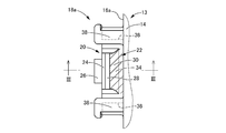
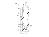
- FIG. III-III sectional view in FIG.
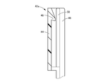
- the top view of the bracket provided in the electrical junction box shown in FIG. FIG. 5 is a VV sectional view in FIG. 4. Sectional drawing which shows the half-fitted state of the principal part shown in FIG. 3 and FIG. Sectional drawing which shows the fitting state of the principal part shown to FIG. 3 and FIG.
- an electrical component module 10 as an assembly member provided with a lock mechanism, and an essential part of an electrical connection box 12 as a mounted member to which the electrical component module 10 is attached. Indicates.
- the electrical component module 10 has a main body 13 as an assembly member main body, which has a box shape of a substantially longitudinal rectangle. Although not shown, a printed circuit board is accommodated in the main body 13, and a plurality of fuse mounting portions 15 are provided on the upper surface 14 of the main body 13. A fuse (not shown) attached to the fuse attaching portion 15 is connected to an internal printed board.
- Lock mechanisms 18a and 18b are provided on side surfaces 16a and 16b at both ends in the longitudinal direction of the main body 13, respectively. Since the lock mechanisms 18a and 18b have the same structure, they are described as the side surface 16 and the lock mechanism 18 unless it is necessary to distinguish between them.
- the lock mechanism 18 is provided with a flexible portion 20.
- the flexible portion 20 is integrally formed on the side surface 16 of the main body 13 made of synthetic resin.
- the flexible portion 20 is connected to the side surface 16 at the base end portion 22, and has a predetermined width dimension (a vertical dimension in FIG. 2) from the base end portion 22 along the side surface 16 of the electric component module 10. It has a hook shape with a substantially L-shaped cross section extending to the upper surface 14 side, and the distal end portion 24 in the extending direction is a free end.
- the latching claw 26 as an engaging part which protrudes outward of the electrical component module 10 is formed.
- a tapered flank 28 that is separated from the side 16 as it goes to the extended end edge (upper end edge in FIG. 3) is formed on the surface of the tip 24 that faces the side 16. .
- the flexible portion 20 is configured such that the distal end portion 24 is a free end, so that the proximal end portion 22 can be bent and deformed, and the proximal end portion 22 is a bending deformation region.
- the cross-sectional shape of the base end portion 22 is a curved shape, and the radius of curvature of the inner side surface 30 sandwiched between the flexible portion 20 and the side surface 16 is the radius of curvature of the outer side surface 32 on the opposite side. Has been bigger than. Thereby, the inner side surface 30 is formed with a larger area than the outer side surface 32.
- a stress luminescent paint 34 as a stress luminescent material is applied to the inner side surface 30 of the base end portion 22. 3 and FIGS. 6 and 7 described later, the thickness of the stress-stimulated luminescent paint 34 is exaggerated.
- the stress-stimulated luminescent coating material 34 is a coating material to which a stress-stimulated luminescent material that emits light when stressed is applied, and preferably emits light in the elastic deformation region, and the luminescence intensity increases according to the magnitude of the applied stress. Adopted. Further, various colors such as green and yellow-orange can be adopted as the luminescent color of the stress luminescent paint 34 in consideration of the color of the coated surface.
- the stress-stimulated luminescent coating material 34 is, for example, a powder of a stress-stimulated luminescent material such as strontium aluminate (SrAl 2 O 4 : Eu) to which europium is added as an emission center, or zinc sulfide (ZnS: Mn) to which manganese is added as an emission center. It is composed of a polymer mixture.
- a stress-stimulated luminescent material such as strontium aluminate (SrAl 2 O 4 : Eu) to which europium is added as an emission center, or zinc sulfide (ZnS: Mn) to which manganese is added as an emission center. It is composed of a polymer mixture.
- a pair of guide grooves 36 and 36 are formed on both sides of the flexible portion 20.
- These guide grooves 36 and 36 are formed in a groove shape that opens on the opposite side (upper and lower sides in FIG. 2) to the flexible portion 20 and extends in the extending direction of the flexible portion 20 (up and down direction in FIG. 1). Yes.
- the guide grooves 36 and 36 are open at the lower end (lower in FIG. 1) in the extending direction, while the upper (upper in FIG. 1) end is blocked by the contact walls 38 and 38. It is.
- the electrical connection box 12 is provided with a module housing portion 40.
- the module housing portion 40 is a concave portion having a substantially longitudinal rectangular shape that can accommodate the electrical component module 10.
- a pair of brackets 42 a and 42 b are provided at both ends in the longitudinal direction of the module housing portion 40. Since these brackets 42a and 42b have the same structure, they will be described without distinction.
- the bracket 42 has a substantially U-shaped cross-sectional shape in which a pair of side walls 46, 46 protrude from both ends of the central wall 44.
- a locking projection 48 as an engaging portion of the attached member is formed at the central portion in the width direction (vertical direction in FIG. 4) of the upper end portion (upper end portion in FIG. 5) of the central wall 44.
- the side walls 46 and 46 are respectively formed with guide ribs 50 and 50 that protrude inward of the bracket 42 and extend in the insertion direction of the electric component module 10 (vertical direction in FIG. 5).
- the electrical component module 10 When assembling the electrical component module 10 in such an electrical junction box 12, the electrical component module 10 is inserted into the module housing portion 40, and the brackets 42a and 42b are inserted into the guide grooves 36 and 36 of the lock mechanisms 18a and 18b. Guide ribs 50 and 50 are inserted. Then, by further inserting the electrical component module 10 in accordance with the guiding action of the guide grooves 36, 36 and the guide ribs 50, 50, the engagement between the locking claw 26 of the flexible portion 20 and the bracket 42 as shown in FIG. The stop protrusion 48 contacts.
- the flexible portion 20 is bent and deformed at the base end portion 22 by the guiding action of the locking claw 26 and the locking projection 48, and the distal end portion 24 is bent and deformed in a direction approaching the side surface 16.
- the flank 28 is formed on the tip 24, the contact between the tip 24 and the side surface 16 is delayed, and the flexible portion 20 can be bent and deformed more greatly.
- the electrical component module 10 is further inserted, and the locking claw 26 of the flexible portion 20 engages the locking protrusion 48 of the bracket 42 downward (downward in FIG. 7).
- the flexible portion 20 is restored by the elastic restoring force.
- the maximum amount of insertion of the electrical component module 10 into the module housing portion 40 is defined by the guide ribs 50 and 50 of the bracket 42 coming into contact with the contact walls 38 and 38 of the guide grooves 36 and 36. .
- the locking claw 26 of the flexible portion 20 is positioned below the locking protrusion 48 of the bracket 42 (downward in FIG. 7).
- the locking claw 26 of the flexible portion 20 is locked by the locking projection 48 and the flexible portion 20 is fitted into the electrical connection box 12, so that the module housing portion 40 of the electrical component module 10 Is prevented from being displaced in the direction of exit (from below to above in FIG. 7).
- the electrical component module 10 is attached to the electrical junction box 12 via the lock mechanisms 18a and 18b.
- the stress light-emitting paint 34 is applied to the base end portion 22 of the flexible portion 20 constituting the lock mechanisms 18a and 18b.
- the stress light-emitting paint 34 emits light. Therefore, for example, in the case where the flexible portion 20 is not normally fitted to the bracket 42 and the flexible portion 20 is in a half-fitted state as shown in FIG. Since the bending deformation has occurred, the stress light-emitting paint 34 emits light.
- the stress light-emitting paint 34 emits light.
- the flexible portion 20 when the flexible portion 20 is normally fitted with the bracket 42, the flexible portion 20 is almost returned to the natural state, and therefore the proximal end portion 22 Hardly undergoes bending deformation, and the stress-stimulated luminescent coating material 34 hardly emits light.
- the fitting state of the lock mechanisms 18a and 18b can be more reliably visually confirmed even when the work place is dark.
- the electrical component module 10 is attached to the concave module housing portion 40 in a housed state, and the lock mechanisms 18a and 18b are connected to the side surfaces 16a and 16b of the electrical component module 10 and the module housing portion 40.
- the lock mechanisms 18a and 18b are provided at both ends in the longitudinal direction of the electrical component module 10 having a long rectangular shape, when the electrical component module 10 is inserted obliquely, the lock mechanisms 18a and 18b. Only one of the two is normally fitted, and the other is likely to be semi-fitted. However, according to the present embodiment, since the half-fitting of the lock mechanisms 18a and 18b can be detected more reliably, both the lock mechanisms 18a and 18b can be reliably fitted to improve manufacturing quality. I can do it.
- the stress luminescent material is provided by applying the stress luminescent coating material 34, the stress luminescent material can be provided in the flexible portion 20 with high manufacturing efficiency and cost efficiency. Furthermore, the present invention can be easily applied to existing lock mechanisms that have been used conventionally.
- the upper side (in FIG. ) To the lock mechanisms 18a and 18b (from the top to the bottom in FIG. 6) is the visual confirmation direction.
- the stress-stimulated luminescent coating material 34 is positioned on the near side in the visual confirmation direction at the base end portion 22 and is first positioned in the visual confirmation direction on the surface of the base end portion 22 and directly with the eyes of the visual confirmer. It is applied to the inner side surface 30 that faces. Thereby, it is possible to more reliably visually recognize the light emission of the stress-stimulated luminescent paint 34.
- the inner side surface 30 is formed with a larger area than the outer side surface 32, it is possible to ensure a wide application region of the stress-stimulated luminescent paint 34. Further, when the base end portion 22 is bent and deformed, the outer surface 32 is deformed in the tensile direction, while the inner surface 30 is deformed in the compression direction. Therefore, by applying the stress luminescent paint 34 to the inner side surface 30, the stress is more effectively applied to the stress luminescent paint 34, and the light emission intensity of the stress luminescent paint 34 can be more advantageously ensured.
- the stress luminescent paint 34 is applied not only to the inner surface 30 at the base end portion 22 of the flexible portion 20 but also to the outer surface 32, or the stress luminescent paint is applied to the entire surface of the flexible portion 20. 34 may be applied.
- the stress-stimulated luminescent material is not limited to the liquid form as in the above-described embodiment, and a solid material can be used.
- the stress-stimulated luminescent material can be flexibly formed by mixing the stress-stimulated luminescent material into a synthetic resin.
- the bending deformation region of the part may be formed of a stress luminescent material.
- the specific shape of the lock mechanism is not limited at all, and various shapes are adopted as the engaging portion of the flexible portion depending on the shape of the engaging portion of the attached member.
- an engagement hole penetrating the flexible portion 20 is provided, and the locking projection 48 of the electrical junction box 12 is engaged with the engagement hole. It may be combined.
- the present invention is not limited to an electric junction box of an automobile.
- the present invention is widely applicable to assembly members in various fields that are attached to a member to be attached via a lock mechanism.
- 10 Electrical component module (an assembly member having a lock mechanism), 12: Electrical junction box (attached member), 13: Main body (assembly member main body), 16a, b: Side surface, 18a, b: Lock mechanism, 20: Flexible part, 22: Base end part (bending deformation area), 24: Tip part, 26: Locking claw (engaging part of flexible part), 30: Inner side surface, 34: Stress luminescent paint (stress luminescent material) , 42a, b: bracket, 48: locking projection (engagement part of attached member)
Landscapes
- Engineering & Computer Science (AREA)
- Microelectronics & Electronic Packaging (AREA)
- Mechanical Engineering (AREA)
- Connection Of Plates (AREA)
- Connection Or Junction Boxes (AREA)
- Details Of Connecting Devices For Male And Female Coupling (AREA)
Description
本発明は、ロック機構を介して被取付部材に取り付けられる、ロック機構を備えた組立部材に関するものである。
従来から、様々な分野において、一方の組立部材を、他方の被取付部材にロック機構を介して取り付けることが行われている。例えば、特開平9-149527号公報(特許文献1)には、自動車に用いられる電気接続箱として、被取付部材としての箱本体に対して、組立部材としての電子ユニットがロック機構を介して取り付けられる構造が開示されている。このようなロック機構としては、組立部材に撓み変形可能とされた可撓部を設けて、該可撓部を一旦撓み変形させることで可撓部に設けられた突起等の係合部を被取付部材との係合位置にまで移動させた後に、係合位置で可撓部を復帰させることによって、可撓部の係合部を被取付部材に設けられた凹部等の係合部と係合させて被取付部材に嵌合する構造が広く用いられている。
ところで、このようなロック機構において、可撓部が撓み変形されたままの半嵌合状態では、組立部材が被取付部材から容易に脱落して損傷したり、特許文献1の如き電気接続箱の場合には、電気部品ユニットが脱落して箱本体との電気的接続が切断されるおそれがある。そこで、ロック機構が半嵌合状態でないか否かを目視で確認することが行われている。
しかし、作業場所が暗い場合には、可撓部の撓み変形の様子を目視することが困難であるという問題があった。特に、ロック機構の配設箇所は、組立部材を被取付部材に固定するという機能の性格上、組立部材と被取付部材に挟まれて暗くなり易い。更に、特許文献1に記載のように、被取付部材を組立部材に収容状態で取り付けるような場合には、ロック機構の配設箇所がより暗くなって、嵌合状態を目視確認することがより困難であった。
本発明は、上述の事情を背景に為されたものであって、その解決課題は、ロック機構の嵌合状態をより確実に目視確認することの出来る、新規な構造のロック機構を備えた組立部材を提供することにある。
本発明の第一の態様は、被取付部材に嵌合する可撓部が設けられており、該可撓部が撓み変形されることによって該可撓部に設けられた係合部が前記被取付部材に設けられた係合部との係合位置に移動されると共に、該可撓部が復帰することによって前記可撓部の係合部が前記被取付部材の係合部と係合されるロック機構を備えた組立部材において、前記可撓部における撓み変形領域に応力発光材料が設けられていることを、特徴とする。
本発明に従う構造とされたロック機構を備えた組立部材においては、ロック機構を構成する可撓部の撓み変形領域に、力学エネルギーによって発光する応力発光材料が設けられている。これにより、可撓部が撓み変形されて、撓み変形領域に応力が及ぼされている場合には、撓み変形領域に設けられた応力発光材料が発光する。従って、可撓部が被取付部材に正常に嵌合している場合には、可撓部が殆ど撓んでいないことから、可撓部は殆ど発光しない。これに対して、半嵌合状態の場合には、可撓部が撓み変形状態とされて撓み変形領域に応力が及ぼされていることから、応力発光材料が発光する。これにより、可撓部が殆ど発光していない場合には正常な嵌合状態であると推測される一方、可撓部が発光している場合には半嵌合状態であることが推測出来、暗所等でも、ロック機構の嵌合状態をより確実に目視確認することが出来る。
なお、応力発光材料としては、応力が及ぼされた際に発光する材料であり、特に弾性変形領域で発光し、加えられる応力の大きさに応じて発光強度が強くなるものが好適に採用される。また、応力発光材料の発光色は、可撓部や被取付部材の色等を考慮して適宜の色が採用可能である。更に、応力発光材料は、塗料に添加して可撓部に塗布されて設けられても良いし、可撓部の撓み変形領域そのものを応力発光材料で形成する等しても良い。応力発光材料の例としては、緑色に発光する、発光中心としてユウロピウムを添加したアルミン酸ストロンチウム(SrAl2 O4 :Eu)や、黄橙色に発光する、発光中心としてマンガンを添加した硫化亜鉛(ZnS:Mn)等が挙げられる。
本発明の第二の態様は、前記第一の態様に記載のものにおいて、前記可撓部における前記撓み変形領域に、前記応力発光材料としての応力発光塗料が塗布されているものである。
本態様においては、応力発光材料が添加された応力発光塗料が撓み変形領域に塗布されている。このようにすれば、撓み変形領域に応力発光材料を容易に設けることが出来、製造効率の向上や製造コストの低減を図ることが出来る。また、可撓部の構造を変更することなく応力発光材料を設けられることから、既存のロック機構に対して、設計変更を要することなく本発明を適用することも出来る。
本発明の第三の態様は、前記第一又は第二の態様に記載のものにおいて、前記応力発光材料が、前記可撓部における目視確認方向の手前側の面に設けられているものである。
本態様によれば、応力発光材料の発光具合をより容易且つ確実に目視することが出来る。これにより、他部材で遮蔽される等して、撓み変形領域の形状の変化を目視で確認し難い場合でも、撓み変形領域の発光の強さから、撓み変形量を推測することが出来る。なお、目視確認方向の手前側の面は、ロック機構の具体的形状やロック機構周囲の部材形状等に応じて適宜に設定される。例えば、撓み変形領域において、目視確認者の目から撓み変形領域に向かう視線上で、視線と最初に交叉する面や、より好ましくは、他部材等に遮蔽されることなく、目視確認者の目と直接に対峙可能な面が採用され得る。
本発明の第四の態様は、前記第一~第三の何れか1つの態様に記載のものにおいて、前記可撓部が、基端部において組立部材本体と連結されている一方、先端部において自由端とされたフック形状とされており、前記基端部が前記撓み変形領域とされていると共に、前記基端部の内側面に前記応力発光材料が設けられているものである。
本態様における基端部の内側面とは、可撓部と組立部材本体で挟まれる側の面を言う。本態様によれば、可撓部と組立部材本体で挟まれて暗くなり易く、視認困難な内側面に応力発光材料を設けることによって、基端部の撓み変形量の目視確認をより容易にすることが出来る。また、可撓部の先端側から応力発光材料を目視することが可能となり、他部材で遮蔽される等して、基端部が側面から視認困難な場合でも、可撓部の先端側から応力発光材料の発光具合を視認することによって、基端部の撓み変形量を目視確認可能とすることが出来る。
本発明においては、組立部材のロック機構を構成する可撓部の撓み変形領域に応力発光材料を設けて、可撓部が撓み変形された半嵌合状態の場合には撓み変形領域が発光するようにした。これにより、作業場所の照明や、ロック機構の配設位置等に起因して可撓部が暗く視認困難な場合でも、撓み変形領域の発光具合からロック機構の嵌合状態をより確実に目視確認することが出来る。その結果、目視確認の作業効率の向上が図られると共に、半嵌合状態のまま出荷するおそれを低減して、品質の向上を図ることが出来る。
以下、本発明の実施形態について、図面を参照しつつ説明する。
先ず、図1に、本発明の一実施形態に係る、ロック機構を備えた組立部材としての電気部品モジュール10と、該電気部品モジュール10が取り付けられる被取付部材としての電気接続箱12の要部を示す。
電気部品モジュール10は、略長手矩形の箱体形状とされた、組立部材本体としての本体13を有している。図示は省略するが、本体13の内部にはプリント基板が収容されており、本体13の上面14には複数のヒューズ装着部15が設けられている。そして、ヒューズ装着部15に装着される図示しないヒューズが、内部のプリント基板と接続されるようになっている。
本体13の長手方向両端の側面16a,16bには、ロック機構18a,18bがそれぞれ設けられている。ロック機構18a,18bは互いに同様の構造であることから、特に区別する必要のない場合には、側面16およびロック機構18として説明する。
図2および図3に示すように、ロック機構18には、可撓部20が設けられている。可撓部20は、合成樹脂からなる本体13の側面16に一体形成されている。可撓部20は、基端部22において側面16に連結されていると共に、基端部22から側面16に沿って、所定の幅寸法(図2中、上下方向寸法)をもって電気部品モジュール10の上面14側に延出する略L字断面のフック形状とされており、延出方向の先端部24が自由端とされている。そして、可撓部20において、基端部22と先端部24の間には、電気部品モジュール10の外方に突出する係合部としての係止爪26が形成されている。また、先端部24における側面16との対向面には、延出端縁部(図3中、上端縁部)に行くに連れて側面16から離隔するテーパ状の逃げ面28が形成されている。
可撓部20は、先端部24が自由端とされていることにより、基端部22において撓み変形可能とされており、基端部22が撓み変形領域とされている。図3に示すように、基端部22の断面形状は湾曲形状とされており、可撓部20と側面16で挟まれた内側面30の曲率半径が、反対側の外側面32の曲率半径よりも大きくされている。これにより、内側面30が、外側面32よりも広い面積をもって形成されている。
そして、基端部22の内側面30には、応力発光材料としての応力発光塗料34が塗布されている。なお、図3および後述する図6、図7においては、応力発光塗料34の厚さを誇張して図示している。応力発光塗料34は、応力が及ぼされることによって発光する応力発光材料が添加された塗料であり、弾性変形領域で発光し、加えられる応力の大きさに応じて発光強度が強くなるものが好適に採用される。また、応力発光塗料34の発光色は塗布面の色等を考慮して、例えば緑色や黄橙色等、各種の色が採用可能である。応力発光塗料34は、例えば、発光中心としてユウロピウムを添加したアルミン酸ストロンチウム(SrAl2 O4 :Eu)や、発光中心としてマンガンを添加した硫化亜鉛(ZnS:Mn)等の応力発光材料の粉末とポリマーの混合体等で構成される。
また、ロック機構18において、可撓部20の両側には、一対の案内溝36,36が形成されている。これら案内溝36,36は、可撓部20と反対側(図2中、上下両側)に開口して可撓部20の延出方向(図1中、上下方向)に延びる溝形状とされている。案内溝36,36は、延出方向の下方(図1中、下方)の端部が開放されている一方、上方(図1中、上方)の端部は当接壁38,38で塞がれている。
一方、電気接続箱12には、モジュール収容部40が設けられている。モジュール収容部40は、電気部品モジュール10を収容可能な大きさの、略長手矩形の凹状部とされている。そして、モジュール収容部40における長手方向の両端部には、一対のブラケット42a,42bが設けられている。これらブラケット42a,42bは互いに同様の構造とされていることから、特に区別することなく説明する。図4および図5にも示すように、ブラケット42は、中央壁44の両端から一対の側壁46,46が突出された略コの字の断面形状を有している。そして、中央壁44の上端部(図5中、上端部)における幅方向(図4の上下方向)の中央部分には、被取付部材の係合部としての係止突起48が形成されている。また、側壁46,46には、ブラケット42の内方に突出して、電気部品モジュール10の差込方向(図5中、上下方向)に延びる案内リブ50,50がそれぞれ形成されている。
このような電気接続箱12に電気部品モジュール10を組み付ける際には、モジュール収容部40に、電気部品モジュール10を差し込んで、ロック機構18a,18bの案内溝36,36に、ブラケット42a,42bの案内リブ50,50を挿し入れる。そして、案内溝36,36と案内リブ50,50との案内作用に従って、電気部品モジュール10を更に差し込むことによって、図6に示すように、可撓部20の係止爪26とブラケット42の係止突起48が接触する。これにより、係止爪26と係止突起48との案内作用によって、可撓部20が基端部22において撓み変形されて、先端部24が側面16に接近する方向に撓み変形される。なお、先端部24に逃げ面28が形成されていることにより、先端部24と側面16との接触を遅らせて、可撓部20をより大きく撓み変形させることが可能とされている。
そして、図7に示すように、電気部品モジュール10が更に差し込まれて、可撓部20の係止爪26がブラケット42の係止突起48を下方(図7中、下方)に乗り越えた係合位置に位置された時点で、可撓部20が弾性復元力によって復帰する。なお、電気部品モジュール10のモジュール収容部40への最大差込量は、ブラケット42の案内リブ50,50が案内溝36,36の当接壁38,38に当接されることで規定される。これにより、可撓部20の係止爪26がブラケット42の係止突起48の下方(図7中、下方)に位置される。その結果、可撓部20の係止爪26が係止突起48で係止されて、可撓部20が電気接続箱12に嵌合されることにより、電気部品モジュール10のモジュール収容部40からの抜け出し方向(図7中、下方から上方)への変位が阻止される。このようにして、電気部品モジュール10が、ロック機構18a,18bを介して、電気接続箱12に取り付けられる。
本実施形態に従う構造とされた電気部品モジュール10によれば、ロック機構18a,18bを構成する可撓部20の基端部22に、応力発光塗料34が塗布されている。これにより、基端部22が撓み変形されて、応力発光塗料34に応力が及ぼされている場合には、応力発光塗料34が発光する。従って、例えば可撓部20がブラケット42と正常に嵌合せず、図6に示したような、可撓部20が撓み変形されたままの半嵌合状態の場合には、基端部22に撓み変形が生じていることから、応力発光塗料34が発光する。一方、図7に示したように、可撓部20がブラケット42と正常に嵌合している場合には、可撓部20が殆ど自然状態に復帰されていることから、基端部22には撓み変形が殆ど生じておらず、応力発光塗料34は殆ど発光しない。このように、応力発光塗料34の発光の有無を確認することによって、作業場所が暗い場合でもロック機構18a,18bの嵌合状態をより確実に目視確認することが出来る。特に本実施形態においては、電気部品モジュール10が凹状のモジュール収容部40に収容状態で取り付けられるようになっており、ロック機構18a,18bが電気部品モジュール10の側面16a,16bとモジュール収容部40の内面の間の狭小空間に位置されて目視が困難となり易いが、本実施形態によれば、応力発光塗料34の発光具合を確認することによって、嵌合状態をより容易且つ確実に確認することが出来る。また、長手矩形状とされた電気部品モジュール10の長手方向の両端部にロック機構18a,18bが設けられていることから、電気部品モジュール10を斜めに差し込んだ場合には、ロック機構18a,18bの何れか一方のみが正常に嵌合して、他方に半嵌合状態が生じ易い。しかし、本実施形態によれば、ロック機構18a,18bの半嵌合をより確実に検出出来ることから、ロック機構18a,18bの両方を確実に嵌合して、製造品質の向上を図ることが出来る。
また、応力発光塗料34を塗布することで応力発光材料が設けられていることから、可撓部20に応力発光材料を製造効率およびコスト効率良く設けることが出来る。更に、従来から使用されている既存のロック機構に容易に本発明を適用することも出来る。
さらに、本実施形態における電気部品モジュール10は、凹状のモジュール収容部40に差し込まれて取り付けられることから、ロック機構18a,18bの嵌合状態を目視確認する場合は、上方(図6中、上方)からロック機構18a,18bに向かう方向(図6中の上方から下方)が目視確認方向とされる。そして、応力発光塗料34が、基端部22において目視確認方向の手前側に位置して、基端部22の表面のうち、目視確認方向で最初に位置すると共に目視確認者の目と直接に対峙する内側面30に塗布されている。これにより、応力発光塗料34の発光をより確実に視認することが可能とされている。また、外側面32よりも内側面30が広い面積をもって形成されていることから、応力発光塗料34の塗布領域を広く確保することが可能とされている。更に、基端部22が撓み変形されるに際して、外側面32は引張方向に変形されるのに対して、内側面30は圧縮方向に変形される。従って、内側面30に応力発光塗料34を塗布することによって、応力発光塗料34に応力をより有効に及ぼして、応力発光塗料34の発光強度をより有利に確保することが出来る。
以上、本発明の実施形態について詳述したが、本発明はその具体的な記載によって限定されない。例えば、前記実施形態において、可撓部20の基端部22における内側面30のみならず、外側面32にも応力発光塗料34を塗布したり、可撓部20の表面の全面に応力発光塗料34を塗布しても良い。
さらに、応力発光材料は、前記実施形態の如き塗料とされて液状を有するものに限定されず、固形のものも採用可能であり、例えば応力発光材料を合成樹脂に混入する等して、可撓部の撓み変形領域を応力発光材料で形成する等しても良い。
また、ロック機構の具体的形状は何ら限定されるものではなく、可撓部の係合部は、被取付部材の係合部の形状に応じて各種の形状が採用される。例えば、前記実施形態における可撓部20の係止爪26に代えて、可撓部20を貫通する係合孔を設けて、該係合孔に前記電気接続箱12の係止突起48を係合させる等しても良い。
更にまた、本発明は、自動車の電気接続箱に限定して用いられるものではない。本発明は、ロック機構を介して被取付部材に取り付けられる各分野の組立部材に広く適用可能である。
10:電気部品モジュール(ロック機構を備えた組立部材)、12:電気接続箱(被取付部材)、13:本体(組立部材本体)、16a,b:側面、18a,b:ロック機構、20:可撓部、22:基端部(撓み変形領域)、24:先端部、26:係止爪(可撓部の係合部)、30:内側面、34:応力発光塗料(応力発光材料)、42a,b:ブラケット、48:係止突起(被取付部材の係合部)
Claims (4)
- 被取付部材に嵌合する可撓部が設けられており、該可撓部が撓み変形されることによって該可撓部に設けられた係合部が前記被取付部材に設けられた係合部との係合位置に移動されると共に、該可撓部が復帰することによって前記可撓部の係合部が前記被取付部材の係合部と係合されるロック機構を備えた組立部材において、
前記可撓部における撓み変形領域に応力発光材料が設けられている
ことを特徴とするロック機構を備えた組立部材。 - 前記可撓部における前記撓み変形領域に、前記応力発光材料としての応力発光塗料が塗布されている
請求項1に記載のロック機構を備えた組立部材。 - 前記応力発光材料が、前記可撓部における目視確認方向の手前側の面に設けられている
請求項1又は2に記載のロック機構を備えた組立部材。 - 前記可撓部が、基端部において組立部材本体と連結されている一方、先端部において自由端とされたフック形状とされており、前記基端部が前記撓み変形領域とされていると共に、前記基端部の内側面に前記応力発光材料が設けられている
請求項1~3の何れか1項に記載のロック機構を備えた組立部材。
Applications Claiming Priority (2)
| Application Number | Priority Date | Filing Date | Title |
|---|---|---|---|
| JP2012-019106 | 2012-01-31 | ||
| JP2012019106A JP2013158216A (ja) | 2012-01-31 | 2012-01-31 | ロック機構を備えた組立部材 |
Publications (1)
| Publication Number | Publication Date |
|---|---|
| WO2013115111A1 true WO2013115111A1 (ja) | 2013-08-08 |
Family
ID=48905151
Family Applications (1)
| Application Number | Title | Priority Date | Filing Date |
|---|---|---|---|
| PCT/JP2013/051660 Ceased WO2013115111A1 (ja) | 2012-01-31 | 2013-01-25 | ロック機構を備えた組立部材 |
Country Status (2)
| Country | Link |
|---|---|
| JP (1) | JP2013158216A (ja) |
| WO (1) | WO2013115111A1 (ja) |
Cited By (1)
| Publication number | Priority date | Publication date | Assignee | Title |
|---|---|---|---|---|
| FR3022308A1 (fr) * | 2014-06-13 | 2015-12-18 | Renault Sas | Dispositif de fixation |
Families Citing this family (2)
| Publication number | Priority date | Publication date | Assignee | Title |
|---|---|---|---|---|
| JP6213837B2 (ja) * | 2014-06-11 | 2017-10-18 | トヨタ車体株式会社 | 収容部、及びこれを備えた電気接続箱 |
| JP6721497B2 (ja) * | 2016-12-12 | 2020-07-15 | アイシン精機株式会社 | ドアフレームガーニッシュ |
Citations (2)
| Publication number | Priority date | Publication date | Assignee | Title |
|---|---|---|---|---|
| JPH08222323A (ja) * | 1995-02-14 | 1996-08-30 | Yazaki Corp | 半嵌合検知機能付コネクタ及び半嵌合検査方法 |
| JP2009241272A (ja) * | 2008-03-28 | 2009-10-22 | Brother Ind Ltd | 着脱体の検出装置及び着脱体 |
-
2012
- 2012-01-31 JP JP2012019106A patent/JP2013158216A/ja active Pending
-
2013
- 2013-01-25 WO PCT/JP2013/051660 patent/WO2013115111A1/ja not_active Ceased
Patent Citations (2)
| Publication number | Priority date | Publication date | Assignee | Title |
|---|---|---|---|---|
| JPH08222323A (ja) * | 1995-02-14 | 1996-08-30 | Yazaki Corp | 半嵌合検知機能付コネクタ及び半嵌合検査方法 |
| JP2009241272A (ja) * | 2008-03-28 | 2009-10-22 | Brother Ind Ltd | 着脱体の検出装置及び着脱体 |
Cited By (1)
| Publication number | Priority date | Publication date | Assignee | Title |
|---|---|---|---|---|
| FR3022308A1 (fr) * | 2014-06-13 | 2015-12-18 | Renault Sas | Dispositif de fixation |
Also Published As
| Publication number | Publication date |
|---|---|
| JP2013158216A (ja) | 2013-08-15 |
Similar Documents
| Publication | Publication Date | Title |
|---|---|---|
| US8282252B2 (en) | Vehicle interior light source unit | |
| KR101441265B1 (ko) | 실내 램프의 고정 구조물 | |
| KR101421397B1 (ko) | 전선 유지 및 방수 구조와 led 유닛 | |
| JP6152940B2 (ja) | 照明器具用アダプタ、及び照明器具 | |
| US9673560B2 (en) | Laminated connector | |
| US20070093131A1 (en) | Connector | |
| WO2013115111A1 (ja) | ロック機構を備えた組立部材 | |
| JP2010541188A (ja) | シールドケーブルのための端部コネクタ | |
| US20150118886A1 (en) | Electrical Connector | |
| JP2017204399A (ja) | コネクタ | |
| US20140060877A1 (en) | Electrical junction box | |
| JP2015088338A (ja) | 照明器具用アダプタおよび照明器具 | |
| US9130294B2 (en) | Latchable contact having a primary locking lance overlapped by a side wall | |
| JP6505547B2 (ja) | コネクタ構造 | |
| WO2015019847A1 (ja) | コネクタ | |
| JP6271753B2 (ja) | 照明装置 | |
| US20150035416A1 (en) | Housing Locking Tabs | |
| US20140036514A1 (en) | Led lighting unit | |
| US20140003043A1 (en) | Luminaire | |
| JP2024159429A (ja) | 灯具 | |
| JP2010225369A (ja) | コネクタ | |
| KR20140125447A (ko) | 전선 인출부 구조 | |
| KR101001888B1 (ko) | 플렉시블 케이블용 커넥터 | |
| US20150162694A1 (en) | Locking structure of terminal fitting and bulb socket | |
| JP6695138B2 (ja) | 照明装置及び光源ユニット |
Legal Events
| Date | Code | Title | Description |
|---|---|---|---|
| 121 | Ep: the epo has been informed by wipo that ep was designated in this application |
Ref document number: 13744366 Country of ref document: EP Kind code of ref document: A1 |
|
| NENP | Non-entry into the national phase |
Ref country code: DE |
|
| 122 | Ep: pct application non-entry in european phase |
Ref document number: 13744366 Country of ref document: EP Kind code of ref document: A1 |