WO2013114717A1 - 3次元映像表示装置 - Google Patents
3次元映像表示装置 Download PDFInfo
- Publication number
- WO2013114717A1 WO2013114717A1 PCT/JP2012/080925 JP2012080925W WO2013114717A1 WO 2013114717 A1 WO2013114717 A1 WO 2013114717A1 JP 2012080925 W JP2012080925 W JP 2012080925W WO 2013114717 A1 WO2013114717 A1 WO 2013114717A1
- Authority
- WO
- WIPO (PCT)
- Prior art keywords
- display device
- mirror
- image display
- main body
- screen
- Prior art date
- Legal status (The legal status is an assumption and is not a legal conclusion. Google has not performed a legal analysis and makes no representation as to the accuracy of the status listed.)
- Ceased
Links
Images


Classifications
-
- G—PHYSICS
- G03—PHOTOGRAPHY; CINEMATOGRAPHY; ANALOGOUS TECHNIQUES USING WAVES OTHER THAN OPTICAL WAVES; ELECTROGRAPHY; HOLOGRAPHY
- G03B—APPARATUS OR ARRANGEMENTS FOR TAKING PHOTOGRAPHS OR FOR PROJECTING OR VIEWING THEM; APPARATUS OR ARRANGEMENTS EMPLOYING ANALOGOUS TECHNIQUES USING WAVES OTHER THAN OPTICAL WAVES; ACCESSORIES THEREFOR
- G03B35/00—Stereoscopic photography
- G03B35/18—Stereoscopic photography by simultaneous viewing
-
- G—PHYSICS
- G03—PHOTOGRAPHY; CINEMATOGRAPHY; ANALOGOUS TECHNIQUES USING WAVES OTHER THAN OPTICAL WAVES; ELECTROGRAPHY; HOLOGRAPHY
- G03B—APPARATUS OR ARRANGEMENTS FOR TAKING PHOTOGRAPHS OR FOR PROJECTING OR VIEWING THEM; APPARATUS OR ARRANGEMENTS EMPLOYING ANALOGOUS TECHNIQUES USING WAVES OTHER THAN OPTICAL WAVES; ACCESSORIES THEREFOR
- G03B25/00—Viewers, other than projection viewers, giving motion-picture effects by persistence of vision, e.g. zoetrope
-
- H—ELECTRICITY
- H04—ELECTRIC COMMUNICATION TECHNIQUE
- H04N—PICTORIAL COMMUNICATION, e.g. TELEVISION
- H04N13/00—Stereoscopic video systems; Multi-view video systems; Details thereof
- H04N13/30—Image reproducers
- H04N13/346—Image reproducers using prisms or semi-transparent mirrors
Definitions
- the present invention relates to a 3D video display device, and more particularly to a 3D video display device that displays a 2D video displayed on the 2D video display device as a 3D video using a mirror.
- a 3D image display device in which a mirror assembly composed of a plurality of half mirrors is arranged in a 2D image display device is known.
- Patent Document 1 Patent Document 2, and Patent Document 5
- a virtual image generated by a half mirror from an image displayed on a two-dimensional image display device is simultaneously displayed on a plurality of display surfaces having different depth positions as viewed from the viewer.
- a three-dimensional video display device that generates a stereoscopic video by displaying is disclosed.
- the three-dimensional display device described in Patent Document 1 has been proposed by the present inventor, and this three-dimensional display device is formed such that the heights of a plurality of half-meers are higher as they are closer to the viewer and lower toward the depth direction. By doing so, the image area is generated and the visible range is expanded.
- a 3D image in which a plurality of half mirrors are arranged on a 2D image display device and a planar virtual image is viewed in the depth direction is a 3D image like a book split used on the stage of a play. Don't need special glasses.
- all the factors of vergence, focus adjustment, binocular parallax, and motion parallax are used, which is exactly the same as when viewing normal stereoscopic images. There is no eye fatigue like a 3D image device seen only by the factor.
- Patent Document 3 includes a mechanism for holding a display device having a lenticular three-dimensional display screen on a mobile phone or the like in a reversible manner.
- the technique described in Patent Document 4 is displayed as a stereoscopic image of a virtual image so that it is projected onto a stereoscopic display member made up of a built-in half mirror, concave mirror, etc. and floats in space via a stereoscopic image display window of a mobile phone. To do.
- a mechanism for holding a display device having a three-dimensional display screen by a lenticular method in a reversible manner is essential.
- a user using a mobile phone of a certain communication carrier does not necessarily need this kind of 3D display function, and as a result, purchases a costly mobile phone equipped with the 3D display function. Will be allowed to.
- Patent Document 4 it is essential to provide a mobile phone with a stereoscopic display device including a half mirror, a concave mirror, and the like. Therefore, as in the case of the technique of Patent Document 3, a special mechanism for three-dimensional display is required for the mobile phone, which increases the cost. In addition, since the techniques described in Patent Documents 3 and 4 require a special mechanism for a mobile phone, it is practical to uniformly adopt this three-dimensional display function for mobile phones that are generally popular in communication carrier companies, for example. It is difficult to.
- Patent Document 2 describes that a display device such as a liquid crystal display device can be used as a two-dimensional display unit, and in the embodiment, display control of the display device when displaying a stereoscopic image. Yes. However, there is no particular mention as to how a two-dimensional display device such as a smartphone used in daily life is handled in relation to a stereoscopic display device.
- An object of the present invention is to provide a three-dimensional video display device having a compact structure that allows a video displayed on the screen of the video display device to be viewed as a three-dimensional video. It is another object of the present invention to provide a three-dimensional image display device having a compact structure by rotating and folding a plurality of mirrors that reflect images. The present invention also displays an image displayed on the screen as a three-dimensional image by using an image display device that is used everyday without any special mechanism or modification to the image display device for three-dimensional image display. Another object of the present invention is to provide a three-dimensional video display device.
- the 3D image display apparatus is preferably a 3D image display apparatus that displays an image displayed on the screen of the image display apparatus in a three-dimensional manner using a plurality of mirrors.
- the main body case is formed on a screen for guiding the video display device when the video display device is attached or detached, and on a screen of the video display device when the video display device is attached to the guide.
- a plurality of video regions having positioning portions for properly positioning the plurality of mirrors;
- the image display device When the image display device is guided by the guide and displays a three-dimensional image in a state where the image display device is positioned at the appropriate position by the positioning unit, the plurality of mirrors are viewed on the screen of the image display device.
- the image displayed on the plurality of image areas of the image display device is reflected by the plurality of mirrors while being tilted by a predetermined angle toward the viewer, and displayed as a three-dimensional image to the viewer 3 It is configured as a three-dimensional video display device.
- the mirror case is fixed to the rear part in the depth direction of the main body case so as to be rotatable around an axis,
- the mirror case rotates about the axis toward the main body case, and the plurality of mirrors are inclined at a predetermined angle toward the viewer with respect to the screen of the image display device.
- It is configured as a three-dimensional video display device that is positioned and reflects the video displayed in the video area of the video display device.
- the mirror case and the main body case are integrally formed of synthetic resin.
- the guide includes left and right guides for regulating the width direction of the video display device mounted on the main body case, and an upper guide and a bottom guide for regulating the height direction.
- the positioning part is constituted by a wall formed at the innermost part of the guide.
- the plurality of mirrors are disposed so that the height of the mirrors decreases toward the back, and are rotatably supported in the mirror case.
- the mirror case rotates the mirror case forward facing the viewer side about an axis, thereby A first position where the front end is flush with the screen of the video display device, the plurality of mirrors are tilted and supported at a predetermined angle, and the video displayed on the screen is reflected toward the viewer; A second position where the plurality of mirrors are separated from the screen of the video display device by rotating the mirror case backward about the axis, and the video displayed on the screen of the video display device can be viewed; It is comprised as a three-dimensional video display apparatus which can be moved between.
- the main body case accommodates a portable display device having a screen for displaying a two-dimensional image as the image display device with the operation unit of the display device facing the viewer.
- the present invention it is possible to provide a three-dimensional image display device suitable for storage and carrying by making the bulky half mirror part into a compact structure by folding.
- a three-dimensional image display device suitable for storage and carrying by making the bulky half mirror part into a compact structure by folding.
- by rotating the mirror device part and pulling it away from the screen of the video display device it is possible to switch between the video displayed on the screen and the three-dimensional video with a simple operation.
- it is possible to display a three-dimensional video by using a video display device that is generally put into practical use without modifying the video display device.
- the mirror device can be rotated with respect to the main body case, and a plurality of mirrors that reflect images are rotated and folded to be housed in the mirror device, so that the structure is compact and convenient to carry.
- video display devices having different sizes such as length can be accepted, and the types of display devices capable of viewing three-dimensional video are expanded.
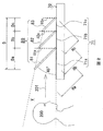
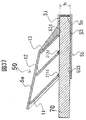
- FIG. 1 and FIG. 2 are a perspective view and a side view showing a positional relationship of elements constituting a 3D video display apparatus according to an embodiment of the present invention.
- the main components of the 3D video display device are a 2D video display device 70 and a mirror device 80 provided on the 2D video display device 70.
- the main components of the mirror device 80 are two flat half mirrors 81 and 82 and one flat full mirror 83. 1 and 2, only the half mirrors 81 and 82 and the full mirror 83 are shown in the mirror device 80, and components for fixing the mirror at a predetermined position are not shown.
- half mirrors 81 and 82 and full mirror 83 reflect the images displayed on the screens 71a, 71b and 71c of the two-dimensional image display device 70 to generate virtual images 81a, 82a and 83a.
- the half mirrors 81 and 82 and the full mirror 83 are arranged with a predetermined interval and a predetermined angle with respect to the screen 71.
- the half mirrors 81 and 82 and the full mirror 83 are inclined on the screen 71 at a fixed angle, and are arranged so that the surfaces of all the half mirrors 81 and 82 and the full mirror 83 are parallel to each other.
- the half mirrors 81 and 82 and the full mirror 83 are preferably disposed at an angle of about 45 ° to the viewer 200 side.
- the two-dimensional image display device 70 is a liquid crystal display, plasma display, LED display, organic EL display, etc. used for flat-screen TVs, mobile phones, smartphones, etc. Including a device having a display such as a player or a touch tablet.
- the viewing area V is wedge-shaped so that the heights of the half mirrors 81 and 82 and the full mirror 83 decrease toward the back as viewed from the viewer 200 (that is, the mirror height gradually decreases).
- the height ratio of the front and rear half mirrors 81 and 82 or the full mirror 83 is the same, and the range is 1: 0.65 to 1: 0.95.
- the length Da of the video area 71a of the half mirror 81 is 0.41D
- the length Db of the video area 71b of the half mirror 82 is 0.33D
- the length of the video area 71c of the full mirror 83 Dc is 0.26D
- the heights Ha, ⁇ ⁇ ⁇ Hb, and ⁇ ⁇ Hc of the half mirrors 81 and 82 and the full mirror 83 are 1.4 times that of Da, Db, and Dc, respectively.
- the width Wm of the half mirrors 81 and 82 and the full mirror 83 is slightly longer than the width W of the screen 71.
- the virtual image 81a in the video area 71a under the half mirror 81, the virtual image 82a in the video area 71b under the half mirror 82, and the virtual image 83a in the video area 71c under the full mirror 83 overlap the depth position in the gaze direction 201 of the viewer 200. It looks like a 3D image.
- a brighter three-dimensional image can be obtained by using a half mirror having a high reflectivity that has not been conventionally used.
- the visible light transmittance of the foremost half mirror 81 viewed from the viewer 200 The reflectance is in the range of 67:33 to 60:40, and the visible light transmittance of the next half mirror 82: reflectance. 50:50 to 55:45, and the visible light reflectivity of the innermost full mirror 83 is 100% to 80%. From the viewer, all virtual images 81a, 81b, 81c have almost the same brightness. It can be seen and an image with sufficient brightness can be obtained even when the lighting is turned on indoors. As a result, it is possible to view a 3D image with brightness with indoor lighting.
- the half mirror 81 may be 67:33, the half mirror 82 may be 50:50, and the reflectance of the full mirror 83 may be 100%. This assumes a case where the reflection performance of the full mirror 83 is high.
- the half mirror 81 is 69:31, the half mirror 82 is 55:45, and the full mirror 83 has a reflectance of 80%. This assumes that the reflection performance of the full mirror 83 is slightly inferior.
- the half mirror 81 is 60:40
- the half mirror 82 is 50:50
- the full mirror 83 has a reflectance of 80%.
- this value is an experimentally obtained value.
- the coating surfaces of the reflecting materials of the half mirrors 81 and 82 and the full mirror 83 are arranged so as to be on the viewer 200 side.
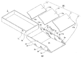
- FIG. 3 is an exploded perspective view showing the overall configuration of a 3D image display apparatus according to a first embodiment of the present invention.
- the two-dimensional image display device 70 is not included in this figure.
- the mirror device 80 includes a mirror case 2, half mirrors 11 and 12, and a full mirror 13. The mirror device 80 can be combined with the main body case 3.
- the main body case 3 has a shape of a container into which the 2D image display device 70 can enter without a gap, and a pair of bearing holes 3k for uniting with the mirror case 2 and a pair of valleys for stabilizing the position of the mirror case 2
- the projection 3j is provided.
- the container of the main body case 3 has a width, a height, and a depth length so that the two-dimensional image display device 70 can be correctly accommodated.
- the video areas 71a, 71b, 71c of the 2D video display device 70 are properly aligned with the half mirrors 11, 12, and the full mirror 13. Represents.
- Mirror case 2 fixes half mirrors 11 and 12 and full mirror 13 at predetermined positions, and has a function of combining with main body case 3.
- the mirror case 2 includes a pair of substantially fan-shaped holes (shaft holes) 2a, 2b, 2c and a pair of stoppers 2d, 2f, 2h for fixing the half mirrors 11, 12 and the full mirror 13, and a pair of claws 2e, 2g and 2i are provided on both sides, and a pair of pivots 2k for merging with the body case and a pair of mountain-shaped protrusions 2j for stabilizing the positions of the mirror case 2 and the body case 3 are provided.
- the material of the main body case 3 and the mirror case 2 is preferably a synthetic resin having elasticity such as polypropylene, polycarbonate, ABS resin, styrene resin, and hard vinyl chloride.
- the half mirrors 11 and 12 and the full mirror 13 are substantially rectangular shapes having rectangular shafts 11a, 12a and 13a on both sides of one side so that they can be inserted into the substantially fan-shaped holes (shaft holes) 2a, 2b and 2c in the mirror case 2.
- the thicknesses of the half mirrors 11 and 12 and the full mirror 13 are preferably 1 mm to 2 mm when the diagonal length of the screen 71 is about 3.5 inches.
- the rectangular shafts 11a, 12a, and 13a are inserted into the substantially fan-shaped holes (shaft holes) 2a, 2b, and 2c.
- the shafts 11a, 12a, and 13a may not be rectangular but may have a pointed conical shape or a polygonal pyramid shape, and the shaft holes 2a, 2b, and 2c that engage with the shafts 11a, 12a, and 13a are not substantially fan-shaped holes, but are merely minute holes. Or a recessed part may be sufficient.
- the half mirrors 11 and 12 and the full mirror 13 are preferably made of glass, acrylic, hard vinyl chloride, or polycarbonate. The color is preferably as transparent as possible.
- the visible light transmittance and reflectance of the half mirrors 11 and 12 are as described above, and the half mirrors 11 and 12 are preferably half mirrors by dielectric multilayer coating in order to reduce the visible light absorption rate.
- the full mirror 13 is preferably a dielectric multilayer coating, but may be an Inconel coating with a metal vapor deposition film.
- FIG. 4 shows a state where the 2D image display device 70 is accommodated in the main body case 3 and the mirror device 80 and the main body case 3 are combined.
- the mirror device 80 is assembled by inserting the shafts of the half mirrors 11 and 12 and the full mirror 13 into the substantially fan-shaped holes 2a, 2b and 2c of the mirror case 2, respectively.
- the mirror device 80 and the main body case 3 can be combined by inserting the pivot 2k of the mirror case 2 into the bearing hole 3k of the main body case 3 (see FIG. 12D).
- the screen 71 can be viewed normally.
- the half mirrors 11 and 12 and the full mirror 13 are not in a predetermined position with respect to the screen 71, 3D video can be viewed. I can't.
- the combination of the main body case 3 and the mirror case 2 is not limited to a structure in which the pivot 2k of the mirror case 2 is inserted into the bearing hole 3k of the main body case 3.
- a mechanism in which a pivot provided in the main body case 3 is combined with a bearing hole provided in the mirror case 2 may be used.
- any mechanism may be used as long as the mirror case 2 is rotatably attached to the main body case 3.
- FIG. 5 is a view showing a state in which the half mirror 11 rotates around the axis.
- FIG. 5A is a perspective view of the half mirror 11
- FIG. 5B is a side view.
- the axis 11a of the half mirror 11 is a rectangle protruding outward, the length is d, and the width is w.
- the length d is equal to the diameter of the substantially fan-shaped bearing hole 2a.
- the half mirror 11 having the rectangular shafts 11a on both sides rotates around the rotating shaft 101 within the range of the substantially fan-shaped fan apex angle ⁇ without falling off by being sandwiched by the substantially fan-shaped bearing holes 2a (see FIG. 3) from both sides. Fixed as possible.
- the half mirror 11 can be rotated to the position indicated by the dotted half mirror 11 without the rotation axis being shaken.
- the shaft of the rotating part is usually thin, but considering that the half mirror 11 is made of glass or synthetic resin, the shaft 11a is made rectangular to increase the strength and reduce the risk of the shaft falling off. Yes.
- the half mirror 12 and the full mirror 13 are also fixed while being able to rotate by the substantially fan-shaped bearing holes 2b and 2c, respectively.
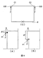
- FIG. 6 and FIG. 7 are diagrams illustrating the strength of the shafts 11a, 12a, and 13a of the half mirrors 11 and 12 and the full mirror 13.
- FIG. FIGS. 6A and 6B are diagrams showing axes having different shapes of d1 and d2.
- the shafts 11a, 12a, and 13a are all shaped as 100 in FIG. In the case of such a shape, stress concentration with respect to the load often occurs in the corner portions C1 and C2.
- stress concentration of the maximum principal stress occurs in the corner portions C1 and C2.
- the maximum principal stress ⁇ b of the corner portion is about 0.3.
- the corner portion stress is reduced by increasing the ratio of the length d2 to the shaft width w.
- the ratio of width w: length d2 is preferably 1: 4 or more, and by setting the ratio to 1: 5, the stress at the corner portion can be reduced to about one third compared to the case of 1: 1.
- FIG. 7 is a diagram showing an example of changing the shape of the shaft. As shown in FIG. 7, the stress can be further dispersed by attaching R to corner portions C1 and C2 (see FIG. 6C) where the axes of the half mirrors 11 and 12 and the full mirror 13 are formed. .
- the radius r of R is preferably 1/3 to 1/4 of w.
- the half mirror 11 is not allowed to rotate because it is in the state of entering the stopper 2d and the claw 2e (see FIGS. 9A, 9B, and 3) provided in the mirror case 2. Is in a state.
- the half mirror 12 and the full mirror 13 are not allowed to rotate by the stoppers 2f and 2h and the claws 2g and 2i. (See FIG. 9A).
- FIG. 8 and FIG. 9 show a state in which the mirror device 80 is rotated around the pivot 2k and covered on the main body case 3 containing the 2D image display device 70 from the state of FIG.
- FIG. 9A is a partial cross-sectional view of a 3D video display device when viewing a 3D video
- FIG. 9B is a cross-sectional view of a portion indicated by an arrow BB in FIG. 9A
- FIG. 9C is a cross-sectional view of a portion indicated by an arrow CC in FIG. 9A.
- the half mirrors 11 and 12 and the full mirror 13 are located at predetermined positions with respect to the screen 71, and the 3D video is viewed in this embodiment.
- the body case 3 and bearing hole 3k, the mirror case 2 and pivot 2k, and the substantially fan-shaped holes 2a, 2b, 2c and stoppers 2d, 2f, 2h, and claws 2e, 2g, 2i are half mirrors for the screen 71 in this state. 11, 12 and the full mirror 13 are arranged to be in a predetermined position.
- the top angles of the substantially fan-shaped holes 2a, 2b, and 2c are about 28 degrees, about 23 degrees, and about 15 degrees, respectively.
- the mountain-shaped protrusion 2j provided in the mirror case 2 is the same as the valley-shaped protrusion 3j of the main body case 3. It is in the valley part. for that reason.
- the positions of the mirror device 80 and the body case 3 are fixed to some extent. Since the mirror case 2 and the main body case 3 are made of an elastic synthetic resin such as polypropylene, the mountain-shaped protrusion 2j is detached from the valley-shaped protrusion 3j with a certain amount of force, and the mirror case 2 is rotated. It can be in the state of. It is possible to change from the state of FIG. 4 to the states of FIGS. 8 and 9 for the same reason.
- the mirror device 80 can be easily rotated and moved in this manner, it is possible to easily switch between the state of viewing the 3D image and the state of viewing the screen 71 of the 2D image display device 70. .
- the screen 71 has a touch panel, the screen can be touched in the state shown in FIG.
- FIG. 10 shows a state in which the mirror is folded in the mirror case 2 from the state of FIG. 10, when the force P1 is applied, the half mirror 11 gets over the claw 2e and folds to the bottom 2n of the mirror case 2 (see FIG. 3).
- the half mirror 12 and the full mirror 13 can be folded in the same manner.
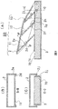
- 11 and 12 show a state in which the mirror case 2 in the state shown in FIG. Unlike the viewing of the 3D image in FIG. 9, the half mirrors 11 and 12 and the full mirror 13 are folded in the mirror case 2, and the mirror device 80 is folded close to the main body case 3 and the 2D image display device 70. It is. It can be seen that the overall volume is reduced compared to the time of viewing in FIG.
- FIG. 12A is a partial cross-sectional view at the time of folding
- FIG. 12B is a cross-sectional view of a portion indicated by an arrow BB in FIG. 12A
- FIG. FIG. 12A is a cross-sectional view of a portion indicated by an arrow CC in FIG. 12A
- FIG. 12D is a cross-sectional view of a portion indicated by an arrow DD in FIG.
- the half mirror 11 is displaced from the stopper 2d and the claw 2e.
- FIG. 12C the mountain-shaped protrusion 2j deviates from the valley-shaped protrusion 3j.
- Fig. 13 shows how half mirrors 11 and 12 and full mirror 13 are folded into mirror case 2.
- the bottom 2n ′ of the mirror case 2 is not flat and is a flat plate, the half mirrors 11 and 12 and the full mirror 13 are folded into the mirror case, and the mirror case 2 is further covered with the main body case 3.
- the rotation axis k 'connecting the mirror case 2 and the main body case 3 must be located away from the main body case 3, and the two cannot be combined.
- the height h2 when the bottom 2n ′ and the screen 71 are folded is the same as when viewing the 3D image.
- the height is about 40% of hmax.
- the end 2w 'of the mirror case 2 has the highest height, and this height is the height h2 when folded.
- FIG. 13C shows a case where the bottom 2n of the mirror case 2 is folded at 2v near the upper end of the full mirror 13.
- FIG. 13C shows a case where the bottom 2n of the mirror case 2 is folded at 2v near the upper end of the full mirror 13.
- the position 2v of the mirror case 2 is the maximum height, and the height h3 when folded is an ornamental It can be about 30% of the height hmax.
- the position 2v having the highest height comes near the center of the bottom 2n of the mirror case 2, it has a non-angular shape in which the center swells compared to FIG. 13B, and is suitable for carrying.
- the bottom 2n of the mirror case 2 is folded in the vicinity of 2v, there is a space for the full mirror 13 to be accommodated, so that the folding of the full mirror 13 is not affected.
- FIG. 14 is a perspective view showing the upper surface of the mirror case.
- the bottom of the mirror case 2 has U-shaped cuts 2p, 2q, 2r.
- force P2 such as a finger or hand
- the inside of the cut can be bent toward the half mirror 11 by the elasticity of synthetic resin.
- the portion 2s hits the half mirror 11 to be pushed out, and can be rotated from the folded state to a position between the stopper 2d and the claw 2e.
- the half mirror 11 can be rotated without directly touching the half mirror 11 with a finger or hand.
- the half mirror 12 and the full mirror 13 can be rotated without touching them directly with a finger or the like by applying force to the 2t and 2u portions.
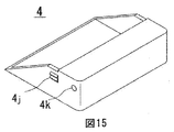
- FIG. 15 is a perspective view showing a main body case 4 having a different form from the main body case 3.
- the main body case 4 has a shape that covers only the end of the two-dimensional image display device 70 without any gap.
- FIG. 16 is a cross-sectional view of a state in which the two-dimensional video display device 70 is inserted into the main body case 4 and the mirror case 2 is combined.
- the body case 4 is also preferably made of an elastic synthetic resin. Further, the main body case 4 and the 2D image display device 70 are not easily detached by frictional force.
- the bearing hole 4k and the valley-shaped protrusion 4j perform the same functions as the bearing hole 3k and the valley-shaped protrusion 3j of the main body case 3.
- a mirror device such as a half mirror can be easily attached to and detached from the two-dimensional image display device 70 such as a liquid crystal display, and the mirror device can be folded and made compact.
- the viewer can easily carry the 3D video device and easily enjoy the 3D video by attaching the 2D video display device 70 to the 3D video device.
- FIG. 17 is a diagram showing components of the 3D image display apparatus according to the second embodiment of the present invention.
- the two-dimensional image display device 70 is not included in this figure.
- the mirror device 50 includes a mirror case 5a, half mirrors 11 and 12, a full mirror 13, and a main body case 5b. Since the mirror case 5a and the main body case 5b are connected by a hinge portion 5f, it is preferable that the mirror case 5a and the main body case 5b are made by integral molding using a synthetic resin having high hinge resistance such as polypropylene.
- the mirror case 5a has grooves 5c, 5d and 5e for mounting and fixing the half mirrors 11 and 12 and the full mirror 13.
- the thicknesses and materials of the half mirrors 11 and 12 and the full mirror 13, the transmittance and the reflectance are the same as those in the first embodiment, but the shapes are all rectangular.
- the main body case 5b has a shape that covers and supports the tip of the two-dimensional image display device 70 without a gap.
- FIGS. 18 and 19 are views showing a state in which the mirror device 50 is formed by fixing the half mirrors 11 and 12 and the full mirror 13 to the mirror case 5a, and the 2D image display device 70 is put in the main body case 5b. This is a state in which the screen 71 of the two-dimensional video display device 70 is normally viewed.
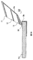
- FIGS. 20 and 21 are views showing a state in which the mirror case 5a is rotated around the hinge 5f and is put on the screen 71.
- FIG. In this state since the half mirrors 11 and 12 and the full mirror 13 are at predetermined positions with respect to the screen 71, a three-dimensional image can be viewed. Since the mirror device 50 can be easily rotated and moved in this way, it is possible to easily switch between the state of viewing a 3D image and the state of viewing the screen 71 of the 2D image display device 70 in a normal manner. .
- the screen 71 is equipped with a touch panel, the screen can be touched in the states of FIGS.
- the volume cannot be reduced by folding the part of the mirror device 50 as in the first embodiment.
- the second embodiment has fewer parts than the first embodiment, and the shape of the parts is simple. Therefore, it is possible to reduce the manufacturing cost compared to the first embodiment.
- the mirror case 5a is structured to be rotatable about the hinge 5f, but the mirror case 5a and the body case 5b may be integrally fixed without providing the hinge 5f.
- the 2D video display device 70 can be inserted and mounted from the front of the main body case 5b.
- the second embodiment it is possible to easily attach and detach a mirror device such as a half mirror to the 2D image display device 70 such as a liquid crystal display and enjoy 3D images.
- a mirror device such as a half mirror
- the 2D image display device 70 such as a liquid crystal display
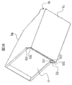
- FIG. 22 is a perspective view of the 3D video display device in a state in which 3D video can be viewed
- FIG. 23 is a 3D image in which the 2D video can be viewed on the screen of the 2D video display device 70 with the mirror device opened.
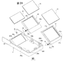
- FIG. 24 is an exploded perspective view of the mirror device
- FIG. 25 is a perspective view of the three-dimensional video display device with the mirror device closed
- FIG. 26 is a perspective view of the mirror device.
- the three-dimensional video display device includes a mirror device 90 and a main body case 3.
- the main body case 3 has a substantially box shape, and the 2D video display device 70 is accommodated therein.
- the 2D video display device 70 is, for example, a smartphone.
- the mirror device 90 includes a substantially box-shaped mirror case 2 on which a plurality of mirrors (three mirrors in this example) are mounted in parallel in the depth direction at a predetermined interval. 2k is supported by a bearing 3k (see FIGS. 27 and 28) at the rear end of the main body case 3 and is rotatable.
- FIG. 23 shows a state in which the mirror case 2 is rotated and completely opened from the main body case 3.
- the 3D image display device is a single box, so that it is compact and easy to store and carry in a bag. Become.
- the main body case 3 is surrounded by a flange (a side wall having a low height) 3i, and a housing 3m surrounded by the flange 3i is provided at the center.
- a 2D video display device 70 having a screen 71 for displaying a 2D video is detachably attached to the housing 3m.
- a pair of guide walls 3b for preventing the 2D image display device 70 from moving to the near side and dropping off is provided on the left and right sides in front. Details of the main body case 3 will be described later with reference to FIGS.
- two half mirrors 11 and 12 and one full mirror 13 are mounted on the mirror case 2 in order from the front.
- Two quadrilateral half mirrors 11 and 12 are attached so as to fit into quadrilateral mirror frames 21 and 22, and quadrilateral full mirror 13 is similarly attached to quadrilateral mirror frame 23.
- the widths of the four-sided shapes of the plurality of mirrors 11, 12, and 13 are the same, but the other side (short side) becomes shorter toward the back (far from the viewer).
- the mirror case 2 and the mirror frames 21, 22, and 23 are preferably formed of a material such as an elastic synthetic resin, such as ABS, polycarbonate, or polypropylene.
- each mirror frame 21 has a pair of shafts 21a. With the torsion coil spring 41 engaged with one of the shafts 21a, the shaft 21a is attached to a pair of bearing portions 20a provided in the mirror case 2. Similarly, the mirror frame 22 fitted with the half mirror 12 is also attached to a pair of bearing portions 20b provided in the mirror case 2 with the torsion coil spring 42 engaged. Since the bearing portions 20a and 20b are made of an elastic synthetic resin, they can be deformed to some extent, and the shafts 21a and 22a of the mirror frames 21 and 22 can be fitted.
- the mirror frames 21 and 22 to which the half mirrors 11 and 12 are attached are forces that cause the mirror frames 21 and 22 to rotate about the axes 21a and 22a by the acting force of the torsion coil springs 41 and 42, respectively.
- the tips 21d and 22d of the mirror frame are brought into close contact with the surface of the screen 71 of the two-dimensional image display device 70 (see FIGS. 29 and 31 for details).
- the mirror frame 23 to which the full mirror 13 is attached is formed integrally with the mirror case 2 and does not rotate. In this state, the tip 20d of the mirror frame 23 forms a surface (S in FIG. 29) in contact with the screen 71 in the same manner as the tips 21d and 22d of the mirror frame.
- the mirror frames 21 and 22 also serve to prevent the tips of the half mirrors 11 and 12 from directly contacting the screen 71 and damaging the screen.
- FIG. 26 is a perspective view showing a state where the assembly of the mirror device 90 is completed.
- a pair of shafts 2k are provided at the rear end of the mirror case 2, and the shaft 2k is engaged with a pair of bearings 3k provided on the main body case 3, so that the mirror device 90 and the main body case 3 are combined. Construct a solid.
- the mirror device 90 to the mirror case 2 can be rotated around the axis 2k with respect to the main body case 3.
- FIG. 22 the 2D image displayed on the screen 71 of the 2D image display device 70 is reflected by the mirrors 21 to 23 in a state where the 2D image display device 70 is accommodated in the housing 3m of the main body case 3.
- the state in which a three-dimensional image is displayed to the viewer is shown.
- FIG. 23 also shows a state in which the 2D video display device 70 is housed in the housing portion 3m of the main body case 3 and the mirror device 90 is rotated and the screen 71 is opened to open the 2D video display device.
- a state in which a normal two-dimensional image displayed on the screen 71 of 70 can be viewed is shown. In this state, 3D images cannot be viewed.
- the screen 71 such as a smartphone has a touch panel function, the screen 71 can be freely touched with a finger or the like even while watching a two-dimensional image.
- FIG. 29 is a side sectional view of the mirror device. With reference to FIG. 29, the operation
- the mirror frame 21 is in a state of being rotatable within a certain range about the axis 21a. However, the rotational force is applied to the mirror frame 21 by the force of the torsion coil spring 41, and the end 21b is in contact with the stopper 20e. In this state, when no force is applied to the mirror frame 21, the mirror frame 21 continues to maintain this position with respect to the mirror case 2.
- the mirror frame 22 is also in the same state as the mirror frame 21. However, in the case of the mirror frame 22, the end 22b is in contact with the bottom surface 20g of the mirror case 2. When a force exceeding a certain level is applied to the mirror frame 22, the end 22 d rotates toward the mirror case 2.
- the torsion coil springs 41 and 42 may be engaged with portions other than the shafts 21a and 22a.
- the end 21d of the mirror frame 21, the end 22d of the mirror frame 22, and the end 20d of the mirror frame 23 are in the same plane S (ie, the screen 71). Furthermore, the center of the pair of axes 2k of the mirror case 2 is also on the same plane S. Further, the reflecting surfaces of the half mirrors 11 and 12 and the full mirror 13 are kept parallel to the plane S at 45 °.
- the reason why the end 21d of the mirror frame 21 is at an angle of 45 ° with respect to the reflecting surface of the half mirror 11 is that when the end 21d contacts the screen 71 of the two-dimensional image display device 70, the two-dimensional This is because the glass half mirror 11 is not damaged by touching the screen 71 of the video display device 70 in as wide an area as possible.
- a socket portion 3e into which the leading portion of the 2D image display device 70 is inserted is provided at the back of the main body case 3, and a part of the socket portion 3e is notched at the bottom of the main body case 3 facing the socket portion 3e. Accordingly, a leaf spring portion 3a that is bent and extended inside the socket portion 3e is provided.
- These components are made of a synthetic resin integrally formed with the main body case 3.
- a pair of soft members 51 made of, for example, sponge or rubber are disposed on the left and right sides of the socket portion 3e.
- FIG. 30 shows the position where the soft member 51 is disposed.
- 30A is a longitudinal sectional view
- FIG. 30B is a plan view
- FIG. 30C is a transverse sectional view.
- the reason why the pair of soft members 51 are arranged inside the socket portion 3e is to accept a plurality of types of two-dimensional image display devices 70 having different widths and to absorb the difference in the widths by the soft members 51.
- the reason why the leaf spring portion 3a is provided at the bottom of the main body case 3 is that there are a plurality of types having different heights between the leaf spring portion 3a and the inside of the socket portion 3e of the main body case 3.
- the two-dimensional image display device 70 is received, and the screen 71 is always in contact with the reference surface 3g by the elastic force of the leaf spring portion 3a. Further, the two-dimensional image display device 70 is held by the pressure of the leaf spring 3a so that the two-dimensional image display device 70 does not easily come out of the socket portion 3e.
- a bearing 3k for rotatably mounting the shaft 2k of the mirror device 90 is provided at the rear end of the main body case 3.
- the bearing 3k is on the same plane R as the reference surface 3g.
- the end portions 21d, 22d, 20d and the axis 2k of each mirror frame in FIG. 29 are on the same plane S.
- the plane S also rotates at the same time, and the plane R and the plane S coincide with each other as shown in FIG. Since the screen 71 of the two-dimensional image display device 70 is in contact with the reference plane 3g, the end portions 21d, 22d, and 20d of each mirror frame are in close contact with the screen 71. In this way, a three-dimensional image can be displayed to the viewer in a state where the half mirrors 11 and 12 and the full mirror 13 are positioned with high accuracy with respect to the screen 71.
- FIG. 31 is a cross-sectional view of the 3D video display device viewed from three directions in a state where the 2D video display device 70 is accommodated in the main body case 3 and a 3D video can be viewed using the mirror device 90.
- the pair of soft members 51 contracts in accordance with the width shape of the 2D image display device 70, and the 2D image display device 70 is moved at a constant pressure. Press down. Since the soft member 51 has a certain friction, the two-dimensional image display device 70 is prevented from being easily removed from the socket portion 3e of the main body case 3.
- the pair of substantially L-shaped walls 3b (FIGS. 30 to 31) provided in front of the main body case 3 prevents the two-dimensional image display device 70 from easily coming off the main body case 3.
- the wall 3b is installed at a position allowing a size slightly larger than the width and length of the two-dimensional image display device 70.
- the leaf spring 3a of the main body case 3 presses the two-dimensional image display device 70 against the reference surface 3g with a constant pressure, and the end of the screen 71 is always at the reference surface 3g. Is in contact with.
- the mirror frame 23 and the mirror case 2 are integrally formed, and the end portion 20d.
- the axis 2k and the combined vertex P (maintaining the angle ⁇ ) of the mirror frame 23 and the mirror case 2 are in a three-point support state and are strong, so the mirror case 2 is a mirror in a parallel arrangement state.
- the external force is not transmitted to the frames 21 and 22. For this reason, even if an external force is applied from the outside of the mirror case 2, it is possible to prevent the mirror frames 21 and 22 in the 3D video display state from being folded in the parallel arrangement state.
- FIG. 32 shows a case where a 2D video display device 60 having a size different from that of the 2D video display device 70 shown in FIG.
- the dimensions Ws2, Ds2, and Ts2 of the two-dimensional image display device 60 in FIG. 32 are all slightly smaller than the dimensions Ws1, Ds1, and Ts1 of the two-dimensional image display device 70 in FIG.
- the soft member 51 holds the two-dimensional image display device 60 with sufficient pressure from the width direction.
- the leaf spring 3a of the main body case 3 presses the two-dimensional image display device 60 against the reference surface 3g with a constant pressure, and the end of the screen 81 is always in contact with the reference surface 3g. Since the soft member 51 has a certain friction, the two-dimensional image display device 60 is prevented from being easily removed from the socket portion 3e of the main body case 3.
- the pair of substantially L-shaped walls 3c shown in FIGS. 30 and 31 prevent the two-dimensional image display device 60 from easily coming off the main body case 3.
- the wall 3c is installed at a position that allows a slightly larger size than the two-dimensional image display device 60. Furthermore, since there is a step between the guide wall 3b and the wall 3c, it is possible to accept both two types of two-dimensional video display devices 70 and 60 having different sizes.
- the bottom 3h of the main body case 3 and the screen 71 are parallel, but in the example of FIG. 32A, the thickness Ts2 of the two-dimensional image display device 60 is thin, so the screen 81 Makes a slight angle ⁇ with the bottom 3h.
- the plane S (FIG. 29) formed by the end portions 21d and 22d and the end portion 20d is in the same plane as the screen 81, and the half mirrors 11 and 12 and the full mirror 13 are higher than the screen 81. It is arranged at a predetermined position with accuracy.
- the two-dimensional image display devices having different sizes by the soft member 51, the leaf spring 3a, and the substantially L-shaped walls 3b and 3c can be accommodated and mounted in the main body case 3. Therefore, it can correspond to a plurality of 2D video display device models.
- the 2D video display device is a smartphone, it is common to always wear a dedicated case called a jacket or the like. Since the dedicated case has a certain thickness, the size of the two-dimensional image display device increases when it is attached.
- the mirror device 90 When removing the 2D video display device 70 from the 3D video display device, as shown in FIG. 23, the mirror device 90 is rotated to be opened from the main body case 3. Then, the two-dimensional video display device 70 is taken out from the housing 3m.
- the height of the flange 3i of the main body case 3 is designed to be lower than the heights of the plural types of two-dimensional image display devices 70, 60, and the side surface 70a of the two-dimensional image display device 70 is exposed from the flange 3i. ing. Therefore, the two-dimensional image display device 70 can be easily detached from the main body case 3 by holding the side surface 70a with a finger. The same applies to the two-dimensional video display device 60 having a different size.
- the mirror frames 21 and 22 are rotated and folded inside the mirror case 2 around the axes 21a and 22a, respectively.
- the torsion coil springs 41 and 42 are repelled and the mirror frames 21 and 22 try to open the mirror case 2, but the mirror frame 21 holds the state in which the hook 20f and the hook hole 3f are engaged and connected.
- 22 is stable in the folded state.
- the three-dimensional image display device is thin and has a single box shape with no protrusions around, so it is compact. It becomes a state suitable for carrying.
- the hook 20f is released by pushing the hook point 20i portion of the mirror case 2, and the mirror case 2 can be opened.
- the mirror frames 21 and 22 are automatically rotated by the repulsive force of the coil springs 41 and 42 to return to the predetermined positions shown in FIG. 22 or FIG.
- the mirror case 5a and the main body case 5b of the mirror device 50 of the three-dimensional image display device are made of synthetic resin having high hinge resistance such as polypropylene, and both are integrally formed. That is, in the second embodiment, the mirror case 5a is fixed to the main body case 5b so as to be rotatable about the hinge portion 5f as a rotation axis, but in the fourth embodiment, both are integrally molded. Since the fourth embodiment has no hinge part and has a simple structure as in the second embodiment, there is an advantage that the durability is higher and the manufacturing cost is lower than that in the second embodiment.
- the upper cover and the left and right side covers are integrally formed to cover the screen 71 of the two-dimensional image display device 70.
- Three parallel grooves are formed on the inner side, and rectangular half mirrors 11 and 12 and a full mirror 13 are fixed to these grooves.
- the thicknesses and materials of the half mirrors 11 and 12 and the full mirror 13, the transmittance, and the reflectance are the same as those in the first embodiment.
- synthetic resin frames 211d and 212d are attached to one side (lower side) of the rectangles of the half mirrors 11 and 12, and when the 2D image display device 70 is attached to and detached from the main body case 5b (frame 211d, In the absence of 212d, one side of the mirror is prevented from coming into direct contact with the screen 71) so that the screen is not damaged.
- the main body case 5b has a box shape to which the tip of the 2D video display device 70 is mounted.
- a guide 53 is provided for guiding and supporting the 2D video display device 70 when displaying a 3D video (FIGS. 36 to 37).
- the guide 53 includes an upper guide 531 on the upper side, a pair of left and right guides 532 provided on the left and right sides, and a bottom plate 533 on the bottom.
- the left and right guides 532 regulate the width of the 2D image display device 70, and the upper guide 531 and the bottom plate (that is, the bottom guide) 533 regulate and guide the height (h) of the 2D image display device 70.
- the main body case 5b has a box shape that restricts and accommodates the tip of the two-dimensional image display device 70, so that the width and height are the same, but the other two lengths are different.
- a three-dimensional image display device 70 can be attached.
- a wall 5p is provided in the innermost part of the main body case 5b (similar to FIGS. 19 and 21), and the two-dimensional image display device 70 is brought into contact with the tip of the two-dimensional image display device 70 by striking the wall 5p.
- Video regions 71a, 71b, 71c can be correctly aligned with the half mirrors 11, 12, and the full mirror 13. In that sense, the innermost wall 5p is a butting portion and has a positioning function.
- the 2D image display device 70 is not sufficiently inserted and the 3D image is displayed in a state where the tip of the 2D image display device 70 is not in contact with the wall 5p, for example, in FIG. 71b and 71c are located in front of the corresponding half mirrors 11 and 12 and full mirror 13. For this reason, the upper or lower part of the two-dimensional image displayed in the video regions 71a, 71b, 71c deviates from the corresponding mirror, or the two-dimensional images from the two video regions (eg, 71a, 71b) are the same mirror (eg, half mirror). It may become a virtual image projected in 11). This is not a sufficient 3D image display, and the viewer cannot be satisfied.
- the 2D image display device 70 is mounted so as to abut against the innermost wall 5p.
- the innermost wall 5p is not necessarily a wall, and is a positioning mechanism such as a protrusion that can position the image area of the 2D image display device 70 with respect to the half mirror and the full mirror. Also good.
- the 2D video display device 70 used in the 3D display device is preferably a smartphone. As shown in FIGS. 34 to 35, a home button 72 operated by a user, menus and applications displayed on the screen are displayed. A plurality of display marks (usually called icons) 73 that are selected and operated by a touch method, and a sensor 74 that controls the brightness and brightness of the screen in accordance with external light are provided at the tip. Corresponding to the position of the sensor 74 when the 2D image display device 70 is attached to the main body case 5b, a hole 5j is provided at the tip of the main body case 5b, and external light is guided to the sensor 74 through the hole 5j. Yes.
- the viewer When viewing a 3D image, the viewer moves the 2D image display device 70 from the front of the main body case 5b with the operation unit (home button 72 or a plurality of display marks 73) of the 2D image display device 70 facing forward. It is inserted into the guide 53 of the main body case 5b (in the direction of the arrow in FIG. 35) and pushed in until the tip of the two-dimensional image display device 70 abuts against the wall 5p.
- the tip of the two-dimensional image display device 70 hits the wall 5p, the state shown in FIG. 37 (or FIG. 2) is obtained, and the image regions 71a, 71b, 71c of the two-dimensional image display device 70 are half mirrors 11, 12, and full mirrors. 13 is correctly aligned, and the 3D image can be properly viewed.
- the viewer can operate the operation unit of the 2D video display device 70 from the front while viewing the 3D video.
- FIG. 38 shows another example.
- the same parts as those in FIGS. 34 to 37 are denoted by the same reference numerals.
- the two-dimensional image display device 70 is supported by being attached to and detached from the bottom of the two-dimensional video display device 70 guided by the bottom guide 534. According to this example, since the mirrors 11, 12, and 13 are exposed to the lower side as compared with the above example, these mirrors can be cleaned.
- FIG. 39 shows still another example.
- three guide protrusions (a pair of guide protrusions 535 at the front and one guide protrusion 536 at the rear) are provided.
- These guide protrusions 535 and 536 are made of the same resin as the main body case 5b.
- the pair of front guide protrusions 535 are configured with a deformable thickness.
- the tip of the two-dimensional image display device 70 is hooked on the rear guide protrusion 536, and the pair of front guide protrusions 535 are deformed, thereby the two-dimensional image display device. It can be installed by pushing 70 into the guide 53. The two-dimensional image display device 70 can be removed by deforming the pair of front guide protrusions 535.
- this invention is not limited to the said Example, It can implement in various deformation
- the above embodiment is an example in which a total of three mirrors, that is, two half mirrors and one full mirror at the rear thereof are arranged.
- the present invention is not limited to this, and three or more half mirrors may be arranged. Good.
- the plurality of mirrors are arranged so that the height of the mirrors gradually decreases in the depth direction, but the present invention is not limited to this.
- a plurality of rectangular mirrors having the same size and a plurality of mirrors arranged at the same height in the depth direction may be used.
- the viewing region is narrowed, but the maximum height is reduced, so that compactness will be improved. .
- 81, 82, 11, 12 Half mirror 83, 13, 23: Full mirror 81a, 82a, 83a: Virtual image 2, 5a: Mirror case 3, 4, 5b: Body case 60, 70: Two-dimensional image display device 71: Screen 71a, 71b, 71c: Image area 50, 80, 90: Mirror device 53: Guide
Landscapes
- Physics & Mathematics (AREA)
- General Physics & Mathematics (AREA)
- Engineering & Computer Science (AREA)
- Multimedia (AREA)
- Signal Processing (AREA)
- Devices For Indicating Variable Information By Combining Individual Elements (AREA)
- Stereoscopic And Panoramic Photography (AREA)
- Testing, Inspecting, Measuring Of Stereoscopic Televisions And Televisions (AREA)
Applications Claiming Priority (2)
| Application Number | Priority Date | Filing Date | Title |
|---|---|---|---|
| JP2012019784A JP2013160793A (ja) | 2012-02-01 | 2012-02-01 | 3次元映像表示装置 |
| JP2012-019784 | 2012-02-01 |
Publications (1)
| Publication Number | Publication Date |
|---|---|
| WO2013114717A1 true WO2013114717A1 (ja) | 2013-08-08 |
Family
ID=48904779
Family Applications (1)
| Application Number | Title | Priority Date | Filing Date |
|---|---|---|---|
| PCT/JP2012/080925 Ceased WO2013114717A1 (ja) | 2012-02-01 | 2012-11-29 | 3次元映像表示装置 |
Country Status (2)
| Country | Link |
|---|---|
| JP (1) | JP2013160793A (https=) |
| WO (1) | WO2013114717A1 (https=) |
Cited By (1)
| Publication number | Priority date | Publication date | Assignee | Title |
|---|---|---|---|---|
| JP2015090370A (ja) * | 2013-11-05 | 2015-05-11 | 日東電工株式会社 | 携帯型情報機器用ケースおよび映像表示装置のケース |
Families Citing this family (4)
| Publication number | Priority date | Publication date | Assignee | Title |
|---|---|---|---|---|
| JP7192179B2 (ja) * | 2018-02-26 | 2022-12-20 | 学 羽澤 | 携帯端末用ケース |
| JP6656460B1 (ja) * | 2019-10-04 | 2020-03-04 | 株式会社三菱地所設計 | スクリーン装置 |
| JP7707550B2 (ja) * | 2021-01-14 | 2025-07-15 | Toppanホールディングス株式会社 | 形成材および原稿表示装置 |
| JP7407409B1 (ja) | 2023-02-09 | 2024-01-04 | 有限会社富士洋行 | 景観グッズ |
Citations (2)
| Publication number | Priority date | Publication date | Assignee | Title |
|---|---|---|---|---|
| JP2010117854A (ja) * | 2008-11-12 | 2010-05-27 | Plantec:Kk | スキミング防止用カバー |
| JP4933678B2 (ja) * | 2011-10-14 | 2012-05-16 | 株式会社ライツ | 3次元映像表示装置 |
Family Cites Families (3)
| Publication number | Priority date | Publication date | Assignee | Title |
|---|---|---|---|---|
| JP4049977B2 (ja) * | 2000-09-01 | 2008-02-20 | パイオニア株式会社 | 通信端末装置、および通信端末装置に用いられるレンズアダプタ |
| JP2003179674A (ja) * | 2001-12-11 | 2003-06-27 | Sony Ericsson Mobilecommunications Japan Inc | 携帯通信端末及び携帯通信端末用ケース |
| JP2005119471A (ja) * | 2003-10-16 | 2005-05-12 | Calsonic Kansei Corp | 車両用表示装置 |
-
2012
- 2012-02-01 JP JP2012019784A patent/JP2013160793A/ja active Pending
- 2012-11-29 WO PCT/JP2012/080925 patent/WO2013114717A1/ja not_active Ceased
Patent Citations (2)
| Publication number | Priority date | Publication date | Assignee | Title |
|---|---|---|---|---|
| JP2010117854A (ja) * | 2008-11-12 | 2010-05-27 | Plantec:Kk | スキミング防止用カバー |
| JP4933678B2 (ja) * | 2011-10-14 | 2012-05-16 | 株式会社ライツ | 3次元映像表示装置 |
Non-Patent Citations (1)
| Title |
|---|
| 3D EIZO, TENOHIRA NI ARAWARU, GEKKAN E·COLUMBUS, vol. 37, 28 February 2011 (2011-02-28), pages 53 * |
Cited By (3)
| Publication number | Priority date | Publication date | Assignee | Title |
|---|---|---|---|---|
| JP2015090370A (ja) * | 2013-11-05 | 2015-05-11 | 日東電工株式会社 | 携帯型情報機器用ケースおよび映像表示装置のケース |
| WO2015068424A1 (ja) * | 2013-11-05 | 2015-05-14 | 日東電工株式会社 | 携帯型情報機器用ケースおよび映像表示装置のケース |
| US9698849B2 (en) | 2013-11-05 | 2017-07-04 | Nitto Denko Corporation | Portable information device case and video picture display device case |
Also Published As
| Publication number | Publication date |
|---|---|
| JP2013160793A (ja) | 2013-08-19 |
Similar Documents
| Publication | Publication Date | Title |
|---|---|---|
| EP2645151B1 (en) | Three-dimensional image viewing device | |
| JP5517090B2 (ja) | ポータブル電子装置 | |
| KR101879601B1 (ko) | 입력 및 출력 구조들을 구비한 착용가능한 디바이스 | |
| JP6278349B2 (ja) | 携帯型情報機器用ケースおよび映像表示装置のケース | |
| CN113374778A (zh) | 铰链结构和包括铰链结构的电子装置 | |
| WO2013114717A1 (ja) | 3次元映像表示装置 | |
| CN107153444B (zh) | 一种智能终端及其投影显示方法 | |
| CN102628992A (zh) | 虚像显示装置 | |
| JP2011166742A (ja) | スライド式電子装置 | |
| KR20150027651A (ko) | 스마트폰이 장착되는 두부 탑재형 장치 | |
| JP6173272B2 (ja) | 拡張現実表示装置および拡張現実表示装置 | |
| KR20210081198A (ko) | 비구면미러의 장착구조가 개선된 차량용 헤드업 디스플레이 장치 | |
| KR20210154712A (ko) | 휴대용 전자 디바이스 | |
| WO2012108325A1 (ja) | 携帯型電子機器 | |
| JP2012181625A (ja) | 電子機器 | |
| JP4933678B2 (ja) | 3次元映像表示装置 | |
| KR101964310B1 (ko) | 입체 영상 표시장치 | |
| JP5341162B2 (ja) | 3次元映像表示装置 | |
| HK1178979B (en) | Three-dimensional video display device | |
| WO2012070139A1 (ja) | 3次元映像表示装置 | |
| JP2012123205A (ja) | 折畳み式携帯端末 | |
| JP2012124721A (ja) | 折畳み式携帯端末 | |
| JP5730600B2 (ja) | 携帯型電子機器 | |
| TWI646883B (zh) | 拼接式顯示裝置及筆記型電腦 | |
| TWM573472U (zh) | Electronic product with stereoscopic display device |
Legal Events
| Date | Code | Title | Description |
|---|---|---|---|
| 121 | Ep: the epo has been informed by wipo that ep was designated in this application |
Ref document number: 12867495 Country of ref document: EP Kind code of ref document: A1 |
|
| NENP | Non-entry into the national phase |
Ref country code: DE |
|
| 122 | Ep: pct application non-entry in european phase |
Ref document number: 12867495 Country of ref document: EP Kind code of ref document: A1 |