WO2013114717A1 - 3次元映像表示装置 - Google Patents
3次元映像表示装置 Download PDFInfo
- Publication number
- WO2013114717A1 WO2013114717A1 PCT/JP2012/080925 JP2012080925W WO2013114717A1 WO 2013114717 A1 WO2013114717 A1 WO 2013114717A1 JP 2012080925 W JP2012080925 W JP 2012080925W WO 2013114717 A1 WO2013114717 A1 WO 2013114717A1
- Authority
- WO
- WIPO (PCT)
- Prior art keywords
- display device
- mirror
- image display
- main body
- screen
- Prior art date
Links
Images


Classifications
-
- G—PHYSICS
- G03—PHOTOGRAPHY; CINEMATOGRAPHY; ANALOGOUS TECHNIQUES USING WAVES OTHER THAN OPTICAL WAVES; ELECTROGRAPHY; HOLOGRAPHY
- G03B—APPARATUS OR ARRANGEMENTS FOR TAKING PHOTOGRAPHS OR FOR PROJECTING OR VIEWING THEM; APPARATUS OR ARRANGEMENTS EMPLOYING ANALOGOUS TECHNIQUES USING WAVES OTHER THAN OPTICAL WAVES; ACCESSORIES THEREFOR
- G03B35/00—Stereoscopic photography
- G03B35/18—Stereoscopic photography by simultaneous viewing
-
- G—PHYSICS
- G03—PHOTOGRAPHY; CINEMATOGRAPHY; ANALOGOUS TECHNIQUES USING WAVES OTHER THAN OPTICAL WAVES; ELECTROGRAPHY; HOLOGRAPHY
- G03B—APPARATUS OR ARRANGEMENTS FOR TAKING PHOTOGRAPHS OR FOR PROJECTING OR VIEWING THEM; APPARATUS OR ARRANGEMENTS EMPLOYING ANALOGOUS TECHNIQUES USING WAVES OTHER THAN OPTICAL WAVES; ACCESSORIES THEREFOR
- G03B25/00—Viewers, other than projection viewers, giving motion-picture effects by persistence of vision, e.g. zoetrope
-
- H—ELECTRICITY
- H04—ELECTRIC COMMUNICATION TECHNIQUE
- H04N—PICTORIAL COMMUNICATION, e.g. TELEVISION
- H04N13/00—Stereoscopic video systems; Multi-view video systems; Details thereof
- H04N13/30—Image reproducers
- H04N13/346—Image reproducers using prisms or semi-transparent mirrors
Definitions
- the present invention relates to a 3D video display device, and more particularly to a 3D video display device that displays a 2D video displayed on the 2D video display device as a 3D video using a mirror.
- a 3D image display device in which a mirror assembly composed of a plurality of half mirrors is arranged in a 2D image display device is known.
- Patent Document 1 Patent Document 2, and Patent Document 5
- a virtual image generated by a half mirror from an image displayed on a two-dimensional image display device is simultaneously displayed on a plurality of display surfaces having different depth positions as viewed from the viewer.
- a three-dimensional video display device that generates a stereoscopic video by displaying is disclosed.
- the three-dimensional display device described in Patent Document 1 has been proposed by the present inventor, and this three-dimensional display device is formed such that the heights of a plurality of half-meers are higher as they are closer to the viewer and lower toward the depth direction. By doing so, the image area is generated and the visible range is expanded.
- a 3D image in which a plurality of half mirrors are arranged on a 2D image display device and a planar virtual image is viewed in the depth direction is a 3D image like a book split used on the stage of a play. Don't need special glasses.
- all the factors of vergence, focus adjustment, binocular parallax, and motion parallax are used, which is exactly the same as when viewing normal stereoscopic images. There is no eye fatigue like a 3D image device seen only by the factor.
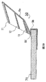
- Patent Document 3 includes a mechanism for holding a display device having a lenticular three-dimensional display screen on a mobile phone or the like in a reversible manner.
- the technique described in Patent Document 4 is displayed as a stereoscopic image of a virtual image so that it is projected onto a stereoscopic display member made up of a built-in half mirror, concave mirror, etc. and floats in space via a stereoscopic image display window of a mobile phone. To do.
- a mechanism for holding a display device having a three-dimensional display screen by a lenticular method in a reversible manner is essential.
- a user using a mobile phone of a certain communication carrier does not necessarily need this kind of 3D display function, and as a result, purchases a costly mobile phone equipped with the 3D display function. Will be allowed to.
- Patent Document 4 it is essential to provide a mobile phone with a stereoscopic display device including a half mirror, a concave mirror, and the like. Therefore, as in the case of the technique of Patent Document 3, a special mechanism for three-dimensional display is required for the mobile phone, which increases the cost. In addition, since the techniques described in Patent Documents 3 and 4 require a special mechanism for a mobile phone, it is practical to uniformly adopt this three-dimensional display function for mobile phones that are generally popular in communication carrier companies, for example. It is difficult to.
- Patent Document 2 describes that a display device such as a liquid crystal display device can be used as a two-dimensional display unit, and in the embodiment, display control of the display device when displaying a stereoscopic image. Yes. However, there is no particular mention as to how a two-dimensional display device such as a smartphone used in daily life is handled in relation to a stereoscopic display device.
- An object of the present invention is to provide a three-dimensional video display device having a compact structure that allows a video displayed on the screen of the video display device to be viewed as a three-dimensional video. It is another object of the present invention to provide a three-dimensional image display device having a compact structure by rotating and folding a plurality of mirrors that reflect images. The present invention also displays an image displayed on the screen as a three-dimensional image by using an image display device that is used everyday without any special mechanism or modification to the image display device for three-dimensional image display. Another object of the present invention is to provide a three-dimensional video display device.
- the 3D image display apparatus is preferably a 3D image display apparatus that displays an image displayed on the screen of the image display apparatus in a three-dimensional manner using a plurality of mirrors.
- the main body case is formed on a screen for guiding the video display device when the video display device is attached or detached, and on a screen of the video display device when the video display device is attached to the guide.
- a plurality of video regions having positioning portions for properly positioning the plurality of mirrors;
- the image display device When the image display device is guided by the guide and displays a three-dimensional image in a state where the image display device is positioned at the appropriate position by the positioning unit, the plurality of mirrors are viewed on the screen of the image display device.
- the image displayed on the plurality of image areas of the image display device is reflected by the plurality of mirrors while being tilted by a predetermined angle toward the viewer, and displayed as a three-dimensional image to the viewer 3 It is configured as a three-dimensional video display device.
- the mirror case is fixed to the rear part in the depth direction of the main body case so as to be rotatable around an axis,
- the mirror case rotates about the axis toward the main body case, and the plurality of mirrors are inclined at a predetermined angle toward the viewer with respect to the screen of the image display device.
- It is configured as a three-dimensional video display device that is positioned and reflects the video displayed in the video area of the video display device.
- the mirror case and the main body case are integrally formed of synthetic resin.
- the guide includes left and right guides for regulating the width direction of the video display device mounted on the main body case, and an upper guide and a bottom guide for regulating the height direction.
- the positioning part is constituted by a wall formed at the innermost part of the guide.
- the plurality of mirrors are disposed so that the height of the mirrors decreases toward the back, and are rotatably supported in the mirror case.
- the mirror case rotates the mirror case forward facing the viewer side about an axis, thereby A first position where the front end is flush with the screen of the video display device, the plurality of mirrors are tilted and supported at a predetermined angle, and the video displayed on the screen is reflected toward the viewer; A second position where the plurality of mirrors are separated from the screen of the video display device by rotating the mirror case backward about the axis, and the video displayed on the screen of the video display device can be viewed; It is comprised as a three-dimensional video display apparatus which can be moved between.
- the main body case accommodates a portable display device having a screen for displaying a two-dimensional image as the image display device with the operation unit of the display device facing the viewer.
- the present invention it is possible to provide a three-dimensional image display device suitable for storage and carrying by making the bulky half mirror part into a compact structure by folding.
- a three-dimensional image display device suitable for storage and carrying by making the bulky half mirror part into a compact structure by folding.
- by rotating the mirror device part and pulling it away from the screen of the video display device it is possible to switch between the video displayed on the screen and the three-dimensional video with a simple operation.
- it is possible to display a three-dimensional video by using a video display device that is generally put into practical use without modifying the video display device.
- the mirror device can be rotated with respect to the main body case, and a plurality of mirrors that reflect images are rotated and folded to be housed in the mirror device, so that the structure is compact and convenient to carry.
- video display devices having different sizes such as length can be accepted, and the types of display devices capable of viewing three-dimensional video are expanded.
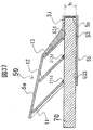
- FIG. 1 and FIG. 2 are a perspective view and a side view showing a positional relationship of elements constituting a 3D video display apparatus according to an embodiment of the present invention.
- the main components of the 3D video display device are a 2D video display device 70 and a mirror device 80 provided on the 2D video display device 70.
- the main components of the mirror device 80 are two flat half mirrors 81 and 82 and one flat full mirror 83. 1 and 2, only the half mirrors 81 and 82 and the full mirror 83 are shown in the mirror device 80, and components for fixing the mirror at a predetermined position are not shown.
- half mirrors 81 and 82 and full mirror 83 reflect the images displayed on the screens 71a, 71b and 71c of the two-dimensional image display device 70 to generate virtual images 81a, 82a and 83a.
- the half mirrors 81 and 82 and the full mirror 83 are arranged with a predetermined interval and a predetermined angle with respect to the screen 71.
- the half mirrors 81 and 82 and the full mirror 83 are inclined on the screen 71 at a fixed angle, and are arranged so that the surfaces of all the half mirrors 81 and 82 and the full mirror 83 are parallel to each other.
- the half mirrors 81 and 82 and the full mirror 83 are preferably disposed at an angle of about 45 ° to the viewer 200 side.
- the two-dimensional image display device 70 is a liquid crystal display, plasma display, LED display, organic EL display, etc. used for flat-screen TVs, mobile phones, smartphones, etc. Including a device having a display such as a player or a touch tablet.
- the viewing area V is wedge-shaped so that the heights of the half mirrors 81 and 82 and the full mirror 83 decrease toward the back as viewed from the viewer 200 (that is, the mirror height gradually decreases).
- the height ratio of the front and rear half mirrors 81 and 82 or the full mirror 83 is the same, and the range is 1: 0.65 to 1: 0.95.
- the length Da of the video area 71a of the half mirror 81 is 0.41D
- the length Db of the video area 71b of the half mirror 82 is 0.33D
- the length of the video area 71c of the full mirror 83 Dc is 0.26D
- the heights Ha, ⁇ ⁇ ⁇ Hb, and ⁇ ⁇ Hc of the half mirrors 81 and 82 and the full mirror 83 are 1.4 times that of Da, Db, and Dc, respectively.
- the width Wm of the half mirrors 81 and 82 and the full mirror 83 is slightly longer than the width W of the screen 71.
- the virtual image 81a in the video area 71a under the half mirror 81, the virtual image 82a in the video area 71b under the half mirror 82, and the virtual image 83a in the video area 71c under the full mirror 83 overlap the depth position in the gaze direction 201 of the viewer 200. It looks like a 3D image.
- a brighter three-dimensional image can be obtained by using a half mirror having a high reflectivity that has not been conventionally used.
- the visible light transmittance of the foremost half mirror 81 viewed from the viewer 200 The reflectance is in the range of 67:33 to 60:40, and the visible light transmittance of the next half mirror 82: reflectance. 50:50 to 55:45, and the visible light reflectivity of the innermost full mirror 83 is 100% to 80%. From the viewer, all virtual images 81a, 81b, 81c have almost the same brightness. It can be seen and an image with sufficient brightness can be obtained even when the lighting is turned on indoors. As a result, it is possible to view a 3D image with brightness with indoor lighting.
- the half mirror 81 may be 67:33, the half mirror 82 may be 50:50, and the reflectance of the full mirror 83 may be 100%. This assumes a case where the reflection performance of the full mirror 83 is high.
- the half mirror 81 is 69:31, the half mirror 82 is 55:45, and the full mirror 83 has a reflectance of 80%. This assumes that the reflection performance of the full mirror 83 is slightly inferior.
- the half mirror 81 is 60:40
- the half mirror 82 is 50:50
- the full mirror 83 has a reflectance of 80%.
- this value is an experimentally obtained value.
- the coating surfaces of the reflecting materials of the half mirrors 81 and 82 and the full mirror 83 are arranged so as to be on the viewer 200 side.
- FIG. 3 is an exploded perspective view showing the overall configuration of a 3D image display apparatus according to a first embodiment of the present invention.
- the two-dimensional image display device 70 is not included in this figure.
- the mirror device 80 includes a mirror case 2, half mirrors 11 and 12, and a full mirror 13. The mirror device 80 can be combined with the main body case 3.
- the main body case 3 has a shape of a container into which the 2D image display device 70 can enter without a gap, and a pair of bearing holes 3k for uniting with the mirror case 2 and a pair of valleys for stabilizing the position of the mirror case 2
- the projection 3j is provided.
- the container of the main body case 3 has a width, a height, and a depth length so that the two-dimensional image display device 70 can be correctly accommodated.
- the video areas 71a, 71b, 71c of the 2D video display device 70 are properly aligned with the half mirrors 11, 12, and the full mirror 13. Represents.
- Mirror case 2 fixes half mirrors 11 and 12 and full mirror 13 at predetermined positions, and has a function of combining with main body case 3.
- the mirror case 2 includes a pair of substantially fan-shaped holes (shaft holes) 2a, 2b, 2c and a pair of stoppers 2d, 2f, 2h for fixing the half mirrors 11, 12 and the full mirror 13, and a pair of claws 2e, 2g and 2i are provided on both sides, and a pair of pivots 2k for merging with the body case and a pair of mountain-shaped protrusions 2j for stabilizing the positions of the mirror case 2 and the body case 3 are provided.
- the material of the main body case 3 and the mirror case 2 is preferably a synthetic resin having elasticity such as polypropylene, polycarbonate, ABS resin, styrene resin, and hard vinyl chloride.
- the half mirrors 11 and 12 and the full mirror 13 are substantially rectangular shapes having rectangular shafts 11a, 12a and 13a on both sides of one side so that they can be inserted into the substantially fan-shaped holes (shaft holes) 2a, 2b and 2c in the mirror case 2.
- the thicknesses of the half mirrors 11 and 12 and the full mirror 13 are preferably 1 mm to 2 mm when the diagonal length of the screen 71 is about 3.5 inches.
- the rectangular shafts 11a, 12a, and 13a are inserted into the substantially fan-shaped holes (shaft holes) 2a, 2b, and 2c.
- the shafts 11a, 12a, and 13a may not be rectangular but may have a pointed conical shape or a polygonal pyramid shape, and the shaft holes 2a, 2b, and 2c that engage with the shafts 11a, 12a, and 13a are not substantially fan-shaped holes, but are merely minute holes. Or a recessed part may be sufficient.
- the half mirrors 11 and 12 and the full mirror 13 are preferably made of glass, acrylic, hard vinyl chloride, or polycarbonate. The color is preferably as transparent as possible.
- the visible light transmittance and reflectance of the half mirrors 11 and 12 are as described above, and the half mirrors 11 and 12 are preferably half mirrors by dielectric multilayer coating in order to reduce the visible light absorption rate.
- the full mirror 13 is preferably a dielectric multilayer coating, but may be an Inconel coating with a metal vapor deposition film.
- FIG. 4 shows a state where the 2D image display device 70 is accommodated in the main body case 3 and the mirror device 80 and the main body case 3 are combined.
- the mirror device 80 is assembled by inserting the shafts of the half mirrors 11 and 12 and the full mirror 13 into the substantially fan-shaped holes 2a, 2b and 2c of the mirror case 2, respectively.
- the mirror device 80 and the main body case 3 can be combined by inserting the pivot 2k of the mirror case 2 into the bearing hole 3k of the main body case 3 (see FIG. 12D).
- the screen 71 can be viewed normally.
- the half mirrors 11 and 12 and the full mirror 13 are not in a predetermined position with respect to the screen 71, 3D video can be viewed. I can't.
- the combination of the main body case 3 and the mirror case 2 is not limited to a structure in which the pivot 2k of the mirror case 2 is inserted into the bearing hole 3k of the main body case 3.
- a mechanism in which a pivot provided in the main body case 3 is combined with a bearing hole provided in the mirror case 2 may be used.
- any mechanism may be used as long as the mirror case 2 is rotatably attached to the main body case 3.
- FIG. 5 is a view showing a state in which the half mirror 11 rotates around the axis.
- FIG. 5A is a perspective view of the half mirror 11
- FIG. 5B is a side view.
- the axis 11a of the half mirror 11 is a rectangle protruding outward, the length is d, and the width is w.
- the length d is equal to the diameter of the substantially fan-shaped bearing hole 2a.
- the half mirror 11 having the rectangular shafts 11a on both sides rotates around the rotating shaft 101 within the range of the substantially fan-shaped fan apex angle ⁇ without falling off by being sandwiched by the substantially fan-shaped bearing holes 2a (see FIG. 3) from both sides. Fixed as possible.
- the half mirror 11 can be rotated to the position indicated by the dotted half mirror 11 without the rotation axis being shaken.
- the shaft of the rotating part is usually thin, but considering that the half mirror 11 is made of glass or synthetic resin, the shaft 11a is made rectangular to increase the strength and reduce the risk of the shaft falling off. Yes.
- the half mirror 12 and the full mirror 13 are also fixed while being able to rotate by the substantially fan-shaped bearing holes 2b and 2c, respectively.
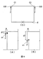
- FIG. 6 and FIG. 7 are diagrams illustrating the strength of the shafts 11a, 12a, and 13a of the half mirrors 11 and 12 and the full mirror 13.
- FIG. FIGS. 6A and 6B are diagrams showing axes having different shapes of d1 and d2.
- the shafts 11a, 12a, and 13a are all shaped as 100 in FIG. In the case of such a shape, stress concentration with respect to the load often occurs in the corner portions C1 and C2.
- stress concentration of the maximum principal stress occurs in the corner portions C1 and C2.
- the maximum principal stress ⁇ b of the corner portion is about 0.3.
- the corner portion stress is reduced by increasing the ratio of the length d2 to the shaft width w.
- the ratio of width w: length d2 is preferably 1: 4 or more, and by setting the ratio to 1: 5, the stress at the corner portion can be reduced to about one third compared to the case of 1: 1.
- FIG. 7 is a diagram showing an example of changing the shape of the shaft. As shown in FIG. 7, the stress can be further dispersed by attaching R to corner portions C1 and C2 (see FIG. 6C) where the axes of the half mirrors 11 and 12 and the full mirror 13 are formed. .
- the radius r of R is preferably 1/3 to 1/4 of w.
- the half mirror 11 is not allowed to rotate because it is in the state of entering the stopper 2d and the claw 2e (see FIGS. 9A, 9B, and 3) provided in the mirror case 2. Is in a state.
- the half mirror 12 and the full mirror 13 are not allowed to rotate by the stoppers 2f and 2h and the claws 2g and 2i. (See FIG. 9A).
- FIG. 8 and FIG. 9 show a state in which the mirror device 80 is rotated around the pivot 2k and covered on the main body case 3 containing the 2D image display device 70 from the state of FIG.
- FIG. 9A is a partial cross-sectional view of a 3D video display device when viewing a 3D video
- FIG. 9B is a cross-sectional view of a portion indicated by an arrow BB in FIG. 9A
- FIG. 9C is a cross-sectional view of a portion indicated by an arrow CC in FIG. 9A.
- the half mirrors 11 and 12 and the full mirror 13 are located at predetermined positions with respect to the screen 71, and the 3D video is viewed in this embodiment.
- the body case 3 and bearing hole 3k, the mirror case 2 and pivot 2k, and the substantially fan-shaped holes 2a, 2b, 2c and stoppers 2d, 2f, 2h, and claws 2e, 2g, 2i are half mirrors for the screen 71 in this state. 11, 12 and the full mirror 13 are arranged to be in a predetermined position.
- the top angles of the substantially fan-shaped holes 2a, 2b, and 2c are about 28 degrees, about 23 degrees, and about 15 degrees, respectively.
- the mountain-shaped protrusion 2j provided in the mirror case 2 is the same as the valley-shaped protrusion 3j of the main body case 3. It is in the valley part. for that reason.
- the positions of the mirror device 80 and the body case 3 are fixed to some extent. Since the mirror case 2 and the main body case 3 are made of an elastic synthetic resin such as polypropylene, the mountain-shaped protrusion 2j is detached from the valley-shaped protrusion 3j with a certain amount of force, and the mirror case 2 is rotated. It can be in the state of. It is possible to change from the state of FIG. 4 to the states of FIGS. 8 and 9 for the same reason.
- the mirror device 80 can be easily rotated and moved in this manner, it is possible to easily switch between the state of viewing the 3D image and the state of viewing the screen 71 of the 2D image display device 70. .
- the screen 71 has a touch panel, the screen can be touched in the state shown in FIG.
- FIG. 10 shows a state in which the mirror is folded in the mirror case 2 from the state of FIG. 10, when the force P1 is applied, the half mirror 11 gets over the claw 2e and folds to the bottom 2n of the mirror case 2 (see FIG. 3).
- the half mirror 12 and the full mirror 13 can be folded in the same manner.
- 11 and 12 show a state in which the mirror case 2 in the state shown in FIG. Unlike the viewing of the 3D image in FIG. 9, the half mirrors 11 and 12 and the full mirror 13 are folded in the mirror case 2, and the mirror device 80 is folded close to the main body case 3 and the 2D image display device 70. It is. It can be seen that the overall volume is reduced compared to the time of viewing in FIG.
- FIG. 12A is a partial cross-sectional view at the time of folding
- FIG. 12B is a cross-sectional view of a portion indicated by an arrow BB in FIG. 12A
- FIG. FIG. 12A is a cross-sectional view of a portion indicated by an arrow CC in FIG. 12A
- FIG. 12D is a cross-sectional view of a portion indicated by an arrow DD in FIG.
- the half mirror 11 is displaced from the stopper 2d and the claw 2e.
- FIG. 12C the mountain-shaped protrusion 2j deviates from the valley-shaped protrusion 3j.
- Fig. 13 shows how half mirrors 11 and 12 and full mirror 13 are folded into mirror case 2.
- the bottom 2n ′ of the mirror case 2 is not flat and is a flat plate, the half mirrors 11 and 12 and the full mirror 13 are folded into the mirror case, and the mirror case 2 is further covered with the main body case 3.
- the rotation axis k 'connecting the mirror case 2 and the main body case 3 must be located away from the main body case 3, and the two cannot be combined.
- the height h2 when the bottom 2n ′ and the screen 71 are folded is the same as when viewing the 3D image.
- the height is about 40% of hmax.
- the end 2w 'of the mirror case 2 has the highest height, and this height is the height h2 when folded.
- FIG. 13C shows a case where the bottom 2n of the mirror case 2 is folded at 2v near the upper end of the full mirror 13.
- FIG. 13C shows a case where the bottom 2n of the mirror case 2 is folded at 2v near the upper end of the full mirror 13.
- the position 2v of the mirror case 2 is the maximum height, and the height h3 when folded is an ornamental It can be about 30% of the height hmax.
- the position 2v having the highest height comes near the center of the bottom 2n of the mirror case 2, it has a non-angular shape in which the center swells compared to FIG. 13B, and is suitable for carrying.
- the bottom 2n of the mirror case 2 is folded in the vicinity of 2v, there is a space for the full mirror 13 to be accommodated, so that the folding of the full mirror 13 is not affected.
- FIG. 14 is a perspective view showing the upper surface of the mirror case.
- the bottom of the mirror case 2 has U-shaped cuts 2p, 2q, 2r.
- force P2 such as a finger or hand
- the inside of the cut can be bent toward the half mirror 11 by the elasticity of synthetic resin.
- the portion 2s hits the half mirror 11 to be pushed out, and can be rotated from the folded state to a position between the stopper 2d and the claw 2e.
- the half mirror 11 can be rotated without directly touching the half mirror 11 with a finger or hand.
- the half mirror 12 and the full mirror 13 can be rotated without touching them directly with a finger or the like by applying force to the 2t and 2u portions.
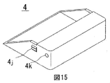
- FIG. 15 is a perspective view showing a main body case 4 having a different form from the main body case 3.
- the main body case 4 has a shape that covers only the end of the two-dimensional image display device 70 without any gap.
- FIG. 16 is a cross-sectional view of a state in which the two-dimensional video display device 70 is inserted into the main body case 4 and the mirror case 2 is combined.
- the body case 4 is also preferably made of an elastic synthetic resin. Further, the main body case 4 and the 2D image display device 70 are not easily detached by frictional force.
- the bearing hole 4k and the valley-shaped protrusion 4j perform the same functions as the bearing hole 3k and the valley-shaped protrusion 3j of the main body case 3.
- a mirror device such as a half mirror can be easily attached to and detached from the two-dimensional image display device 70 such as a liquid crystal display, and the mirror device can be folded and made compact.
- the viewer can easily carry the 3D video device and easily enjoy the 3D video by attaching the 2D video display device 70 to the 3D video device.
- FIG. 17 is a diagram showing components of the 3D image display apparatus according to the second embodiment of the present invention.
- the two-dimensional image display device 70 is not included in this figure.
- the mirror device 50 includes a mirror case 5a, half mirrors 11 and 12, a full mirror 13, and a main body case 5b. Since the mirror case 5a and the main body case 5b are connected by a hinge portion 5f, it is preferable that the mirror case 5a and the main body case 5b are made by integral molding using a synthetic resin having high hinge resistance such as polypropylene.
- the mirror case 5a has grooves 5c, 5d and 5e for mounting and fixing the half mirrors 11 and 12 and the full mirror 13.
- the thicknesses and materials of the half mirrors 11 and 12 and the full mirror 13, the transmittance and the reflectance are the same as those in the first embodiment, but the shapes are all rectangular.
- the main body case 5b has a shape that covers and supports the tip of the two-dimensional image display device 70 without a gap.
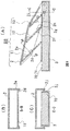
- FIGS. 18 and 19 are views showing a state in which the mirror device 50 is formed by fixing the half mirrors 11 and 12 and the full mirror 13 to the mirror case 5a, and the 2D image display device 70 is put in the main body case 5b. This is a state in which the screen 71 of the two-dimensional video display device 70 is normally viewed.
- FIGS. 20 and 21 are views showing a state in which the mirror case 5a is rotated around the hinge 5f and is put on the screen 71.
- FIG. In this state since the half mirrors 11 and 12 and the full mirror 13 are at predetermined positions with respect to the screen 71, a three-dimensional image can be viewed. Since the mirror device 50 can be easily rotated and moved in this way, it is possible to easily switch between the state of viewing a 3D image and the state of viewing the screen 71 of the 2D image display device 70 in a normal manner. .
- the screen 71 is equipped with a touch panel, the screen can be touched in the states of FIGS.
- the volume cannot be reduced by folding the part of the mirror device 50 as in the first embodiment.
- the second embodiment has fewer parts than the first embodiment, and the shape of the parts is simple. Therefore, it is possible to reduce the manufacturing cost compared to the first embodiment.
- the mirror case 5a is structured to be rotatable about the hinge 5f, but the mirror case 5a and the body case 5b may be integrally fixed without providing the hinge 5f.
- the 2D video display device 70 can be inserted and mounted from the front of the main body case 5b.
- the second embodiment it is possible to easily attach and detach a mirror device such as a half mirror to the 2D image display device 70 such as a liquid crystal display and enjoy 3D images.
- a mirror device such as a half mirror
- the 2D image display device 70 such as a liquid crystal display
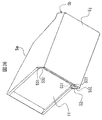
- FIG. 22 is a perspective view of the 3D video display device in a state in which 3D video can be viewed
- FIG. 23 is a 3D image in which the 2D video can be viewed on the screen of the 2D video display device 70 with the mirror device opened.
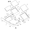
- FIG. 24 is an exploded perspective view of the mirror device
- FIG. 25 is a perspective view of the three-dimensional video display device with the mirror device closed
- FIG. 26 is a perspective view of the mirror device.
- the three-dimensional video display device includes a mirror device 90 and a main body case 3.
- the main body case 3 has a substantially box shape, and the 2D video display device 70 is accommodated therein.
- the 2D video display device 70 is, for example, a smartphone.
- the mirror device 90 includes a substantially box-shaped mirror case 2 on which a plurality of mirrors (three mirrors in this example) are mounted in parallel in the depth direction at a predetermined interval. 2k is supported by a bearing 3k (see FIGS. 27 and 28) at the rear end of the main body case 3 and is rotatable.
- FIG. 23 shows a state in which the mirror case 2 is rotated and completely opened from the main body case 3.
- the 3D image display device is a single box, so that it is compact and easy to store and carry in a bag. Become.
- the main body case 3 is surrounded by a flange (a side wall having a low height) 3i, and a housing 3m surrounded by the flange 3i is provided at the center.
- a 2D video display device 70 having a screen 71 for displaying a 2D video is detachably attached to the housing 3m.
- a pair of guide walls 3b for preventing the 2D image display device 70 from moving to the near side and dropping off is provided on the left and right sides in front. Details of the main body case 3 will be described later with reference to FIGS.
- two half mirrors 11 and 12 and one full mirror 13 are mounted on the mirror case 2 in order from the front.
- Two quadrilateral half mirrors 11 and 12 are attached so as to fit into quadrilateral mirror frames 21 and 22, and quadrilateral full mirror 13 is similarly attached to quadrilateral mirror frame 23.
- the widths of the four-sided shapes of the plurality of mirrors 11, 12, and 13 are the same, but the other side (short side) becomes shorter toward the back (far from the viewer).
- the mirror case 2 and the mirror frames 21, 22, and 23 are preferably formed of a material such as an elastic synthetic resin, such as ABS, polycarbonate, or polypropylene.
- each mirror frame 21 has a pair of shafts 21a. With the torsion coil spring 41 engaged with one of the shafts 21a, the shaft 21a is attached to a pair of bearing portions 20a provided in the mirror case 2. Similarly, the mirror frame 22 fitted with the half mirror 12 is also attached to a pair of bearing portions 20b provided in the mirror case 2 with the torsion coil spring 42 engaged. Since the bearing portions 20a and 20b are made of an elastic synthetic resin, they can be deformed to some extent, and the shafts 21a and 22a of the mirror frames 21 and 22 can be fitted.
- the mirror frames 21 and 22 to which the half mirrors 11 and 12 are attached are forces that cause the mirror frames 21 and 22 to rotate about the axes 21a and 22a by the acting force of the torsion coil springs 41 and 42, respectively.
- the tips 21d and 22d of the mirror frame are brought into close contact with the surface of the screen 71 of the two-dimensional image display device 70 (see FIGS. 29 and 31 for details).
- the mirror frame 23 to which the full mirror 13 is attached is formed integrally with the mirror case 2 and does not rotate. In this state, the tip 20d of the mirror frame 23 forms a surface (S in FIG. 29) in contact with the screen 71 in the same manner as the tips 21d and 22d of the mirror frame.
- the mirror frames 21 and 22 also serve to prevent the tips of the half mirrors 11 and 12 from directly contacting the screen 71 and damaging the screen.
- FIG. 26 is a perspective view showing a state where the assembly of the mirror device 90 is completed.
- a pair of shafts 2k are provided at the rear end of the mirror case 2, and the shaft 2k is engaged with a pair of bearings 3k provided on the main body case 3, so that the mirror device 90 and the main body case 3 are combined. Construct a solid.
- the mirror device 90 to the mirror case 2 can be rotated around the axis 2k with respect to the main body case 3.
- FIG. 22 the 2D image displayed on the screen 71 of the 2D image display device 70 is reflected by the mirrors 21 to 23 in a state where the 2D image display device 70 is accommodated in the housing 3m of the main body case 3.
- the state in which a three-dimensional image is displayed to the viewer is shown.
- FIG. 23 also shows a state in which the 2D video display device 70 is housed in the housing portion 3m of the main body case 3 and the mirror device 90 is rotated and the screen 71 is opened to open the 2D video display device.
- a state in which a normal two-dimensional image displayed on the screen 71 of 70 can be viewed is shown. In this state, 3D images cannot be viewed.
- the screen 71 such as a smartphone has a touch panel function, the screen 71 can be freely touched with a finger or the like even while watching a two-dimensional image.
- FIG. 29 is a side sectional view of the mirror device. With reference to FIG. 29, the operation
- the mirror frame 21 is in a state of being rotatable within a certain range about the axis 21a. However, the rotational force is applied to the mirror frame 21 by the force of the torsion coil spring 41, and the end 21b is in contact with the stopper 20e. In this state, when no force is applied to the mirror frame 21, the mirror frame 21 continues to maintain this position with respect to the mirror case 2.
- the mirror frame 22 is also in the same state as the mirror frame 21. However, in the case of the mirror frame 22, the end 22b is in contact with the bottom surface 20g of the mirror case 2. When a force exceeding a certain level is applied to the mirror frame 22, the end 22 d rotates toward the mirror case 2.
- the torsion coil springs 41 and 42 may be engaged with portions other than the shafts 21a and 22a.
- the end 21d of the mirror frame 21, the end 22d of the mirror frame 22, and the end 20d of the mirror frame 23 are in the same plane S (ie, the screen 71). Furthermore, the center of the pair of axes 2k of the mirror case 2 is also on the same plane S. Further, the reflecting surfaces of the half mirrors 11 and 12 and the full mirror 13 are kept parallel to the plane S at 45 °.
- the reason why the end 21d of the mirror frame 21 is at an angle of 45 ° with respect to the reflecting surface of the half mirror 11 is that when the end 21d contacts the screen 71 of the two-dimensional image display device 70, the two-dimensional This is because the glass half mirror 11 is not damaged by touching the screen 71 of the video display device 70 in as wide an area as possible.
- a socket portion 3e into which the leading portion of the 2D image display device 70 is inserted is provided at the back of the main body case 3, and a part of the socket portion 3e is notched at the bottom of the main body case 3 facing the socket portion 3e. Accordingly, a leaf spring portion 3a that is bent and extended inside the socket portion 3e is provided.
- These components are made of a synthetic resin integrally formed with the main body case 3.
- a pair of soft members 51 made of, for example, sponge or rubber are disposed on the left and right sides of the socket portion 3e.
- FIG. 30 shows the position where the soft member 51 is disposed.
- 30A is a longitudinal sectional view
- FIG. 30B is a plan view
- FIG. 30C is a transverse sectional view.
- the reason why the pair of soft members 51 are arranged inside the socket portion 3e is to accept a plurality of types of two-dimensional image display devices 70 having different widths and to absorb the difference in the widths by the soft members 51.
- the reason why the leaf spring portion 3a is provided at the bottom of the main body case 3 is that there are a plurality of types having different heights between the leaf spring portion 3a and the inside of the socket portion 3e of the main body case 3.
- the two-dimensional image display device 70 is received, and the screen 71 is always in contact with the reference surface 3g by the elastic force of the leaf spring portion 3a. Further, the two-dimensional image display device 70 is held by the pressure of the leaf spring 3a so that the two-dimensional image display device 70 does not easily come out of the socket portion 3e.
- a bearing 3k for rotatably mounting the shaft 2k of the mirror device 90 is provided at the rear end of the main body case 3.
- the bearing 3k is on the same plane R as the reference surface 3g.
- the end portions 21d, 22d, 20d and the axis 2k of each mirror frame in FIG. 29 are on the same plane S.
- the plane S also rotates at the same time, and the plane R and the plane S coincide with each other as shown in FIG. Since the screen 71 of the two-dimensional image display device 70 is in contact with the reference plane 3g, the end portions 21d, 22d, and 20d of each mirror frame are in close contact with the screen 71. In this way, a three-dimensional image can be displayed to the viewer in a state where the half mirrors 11 and 12 and the full mirror 13 are positioned with high accuracy with respect to the screen 71.
- FIG. 31 is a cross-sectional view of the 3D video display device viewed from three directions in a state where the 2D video display device 70 is accommodated in the main body case 3 and a 3D video can be viewed using the mirror device 90.
- the pair of soft members 51 contracts in accordance with the width shape of the 2D image display device 70, and the 2D image display device 70 is moved at a constant pressure. Press down. Since the soft member 51 has a certain friction, the two-dimensional image display device 70 is prevented from being easily removed from the socket portion 3e of the main body case 3.
- the pair of substantially L-shaped walls 3b (FIGS. 30 to 31) provided in front of the main body case 3 prevents the two-dimensional image display device 70 from easily coming off the main body case 3.
- the wall 3b is installed at a position allowing a size slightly larger than the width and length of the two-dimensional image display device 70.
- the leaf spring 3a of the main body case 3 presses the two-dimensional image display device 70 against the reference surface 3g with a constant pressure, and the end of the screen 71 is always at the reference surface 3g. Is in contact with.
- the mirror frame 23 and the mirror case 2 are integrally formed, and the end portion 20d.
- the axis 2k and the combined vertex P (maintaining the angle ⁇ ) of the mirror frame 23 and the mirror case 2 are in a three-point support state and are strong, so the mirror case 2 is a mirror in a parallel arrangement state.
- the external force is not transmitted to the frames 21 and 22. For this reason, even if an external force is applied from the outside of the mirror case 2, it is possible to prevent the mirror frames 21 and 22 in the 3D video display state from being folded in the parallel arrangement state.
- FIG. 32 shows a case where a 2D video display device 60 having a size different from that of the 2D video display device 70 shown in FIG.
- the dimensions Ws2, Ds2, and Ts2 of the two-dimensional image display device 60 in FIG. 32 are all slightly smaller than the dimensions Ws1, Ds1, and Ts1 of the two-dimensional image display device 70 in FIG.
- the soft member 51 holds the two-dimensional image display device 60 with sufficient pressure from the width direction.
- the leaf spring 3a of the main body case 3 presses the two-dimensional image display device 60 against the reference surface 3g with a constant pressure, and the end of the screen 81 is always in contact with the reference surface 3g. Since the soft member 51 has a certain friction, the two-dimensional image display device 60 is prevented from being easily removed from the socket portion 3e of the main body case 3.
- the pair of substantially L-shaped walls 3c shown in FIGS. 30 and 31 prevent the two-dimensional image display device 60 from easily coming off the main body case 3.
- the wall 3c is installed at a position that allows a slightly larger size than the two-dimensional image display device 60. Furthermore, since there is a step between the guide wall 3b and the wall 3c, it is possible to accept both two types of two-dimensional video display devices 70 and 60 having different sizes.
- the bottom 3h of the main body case 3 and the screen 71 are parallel, but in the example of FIG. 32A, the thickness Ts2 of the two-dimensional image display device 60 is thin, so the screen 81 Makes a slight angle ⁇ with the bottom 3h.
- the plane S (FIG. 29) formed by the end portions 21d and 22d and the end portion 20d is in the same plane as the screen 81, and the half mirrors 11 and 12 and the full mirror 13 are higher than the screen 81. It is arranged at a predetermined position with accuracy.
- the two-dimensional image display devices having different sizes by the soft member 51, the leaf spring 3a, and the substantially L-shaped walls 3b and 3c can be accommodated and mounted in the main body case 3. Therefore, it can correspond to a plurality of 2D video display device models.
- the 2D video display device is a smartphone, it is common to always wear a dedicated case called a jacket or the like. Since the dedicated case has a certain thickness, the size of the two-dimensional image display device increases when it is attached.
- the mirror device 90 When removing the 2D video display device 70 from the 3D video display device, as shown in FIG. 23, the mirror device 90 is rotated to be opened from the main body case 3. Then, the two-dimensional video display device 70 is taken out from the housing 3m.
- the height of the flange 3i of the main body case 3 is designed to be lower than the heights of the plural types of two-dimensional image display devices 70, 60, and the side surface 70a of the two-dimensional image display device 70 is exposed from the flange 3i. ing. Therefore, the two-dimensional image display device 70 can be easily detached from the main body case 3 by holding the side surface 70a with a finger. The same applies to the two-dimensional video display device 60 having a different size.
- the mirror frames 21 and 22 are rotated and folded inside the mirror case 2 around the axes 21a and 22a, respectively.
- the torsion coil springs 41 and 42 are repelled and the mirror frames 21 and 22 try to open the mirror case 2, but the mirror frame 21 holds the state in which the hook 20f and the hook hole 3f are engaged and connected.
- 22 is stable in the folded state.
- the three-dimensional image display device is thin and has a single box shape with no protrusions around, so it is compact. It becomes a state suitable for carrying.
- the hook 20f is released by pushing the hook point 20i portion of the mirror case 2, and the mirror case 2 can be opened.
- the mirror frames 21 and 22 are automatically rotated by the repulsive force of the coil springs 41 and 42 to return to the predetermined positions shown in FIG. 22 or FIG.
- the mirror case 5a and the main body case 5b of the mirror device 50 of the three-dimensional image display device are made of synthetic resin having high hinge resistance such as polypropylene, and both are integrally formed. That is, in the second embodiment, the mirror case 5a is fixed to the main body case 5b so as to be rotatable about the hinge portion 5f as a rotation axis, but in the fourth embodiment, both are integrally molded. Since the fourth embodiment has no hinge part and has a simple structure as in the second embodiment, there is an advantage that the durability is higher and the manufacturing cost is lower than that in the second embodiment.
- the upper cover and the left and right side covers are integrally formed to cover the screen 71 of the two-dimensional image display device 70.
- Three parallel grooves are formed on the inner side, and rectangular half mirrors 11 and 12 and a full mirror 13 are fixed to these grooves.
- the thicknesses and materials of the half mirrors 11 and 12 and the full mirror 13, the transmittance, and the reflectance are the same as those in the first embodiment.
- synthetic resin frames 211d and 212d are attached to one side (lower side) of the rectangles of the half mirrors 11 and 12, and when the 2D image display device 70 is attached to and detached from the main body case 5b (frame 211d, In the absence of 212d, one side of the mirror is prevented from coming into direct contact with the screen 71) so that the screen is not damaged.
- the main body case 5b has a box shape to which the tip of the 2D video display device 70 is mounted.
- a guide 53 is provided for guiding and supporting the 2D video display device 70 when displaying a 3D video (FIGS. 36 to 37).
- the guide 53 includes an upper guide 531 on the upper side, a pair of left and right guides 532 provided on the left and right sides, and a bottom plate 533 on the bottom.
- the left and right guides 532 regulate the width of the 2D image display device 70, and the upper guide 531 and the bottom plate (that is, the bottom guide) 533 regulate and guide the height (h) of the 2D image display device 70.
- the main body case 5b has a box shape that restricts and accommodates the tip of the two-dimensional image display device 70, so that the width and height are the same, but the other two lengths are different.
- a three-dimensional image display device 70 can be attached.
- a wall 5p is provided in the innermost part of the main body case 5b (similar to FIGS. 19 and 21), and the two-dimensional image display device 70 is brought into contact with the tip of the two-dimensional image display device 70 by striking the wall 5p.
- Video regions 71a, 71b, 71c can be correctly aligned with the half mirrors 11, 12, and the full mirror 13. In that sense, the innermost wall 5p is a butting portion and has a positioning function.
- the 2D image display device 70 is not sufficiently inserted and the 3D image is displayed in a state where the tip of the 2D image display device 70 is not in contact with the wall 5p, for example, in FIG. 71b and 71c are located in front of the corresponding half mirrors 11 and 12 and full mirror 13. For this reason, the upper or lower part of the two-dimensional image displayed in the video regions 71a, 71b, 71c deviates from the corresponding mirror, or the two-dimensional images from the two video regions (eg, 71a, 71b) are the same mirror (eg, half mirror). It may become a virtual image projected in 11). This is not a sufficient 3D image display, and the viewer cannot be satisfied.
- the 2D image display device 70 is mounted so as to abut against the innermost wall 5p.
- the innermost wall 5p is not necessarily a wall, and is a positioning mechanism such as a protrusion that can position the image area of the 2D image display device 70 with respect to the half mirror and the full mirror. Also good.
- the 2D video display device 70 used in the 3D display device is preferably a smartphone. As shown in FIGS. 34 to 35, a home button 72 operated by a user, menus and applications displayed on the screen are displayed. A plurality of display marks (usually called icons) 73 that are selected and operated by a touch method, and a sensor 74 that controls the brightness and brightness of the screen in accordance with external light are provided at the tip. Corresponding to the position of the sensor 74 when the 2D image display device 70 is attached to the main body case 5b, a hole 5j is provided at the tip of the main body case 5b, and external light is guided to the sensor 74 through the hole 5j. Yes.
- the viewer When viewing a 3D image, the viewer moves the 2D image display device 70 from the front of the main body case 5b with the operation unit (home button 72 or a plurality of display marks 73) of the 2D image display device 70 facing forward. It is inserted into the guide 53 of the main body case 5b (in the direction of the arrow in FIG. 35) and pushed in until the tip of the two-dimensional image display device 70 abuts against the wall 5p.
- the tip of the two-dimensional image display device 70 hits the wall 5p, the state shown in FIG. 37 (or FIG. 2) is obtained, and the image regions 71a, 71b, 71c of the two-dimensional image display device 70 are half mirrors 11, 12, and full mirrors. 13 is correctly aligned, and the 3D image can be properly viewed.
- the viewer can operate the operation unit of the 2D video display device 70 from the front while viewing the 3D video.
- FIG. 38 shows another example.
- the same parts as those in FIGS. 34 to 37 are denoted by the same reference numerals.
- the two-dimensional image display device 70 is supported by being attached to and detached from the bottom of the two-dimensional video display device 70 guided by the bottom guide 534. According to this example, since the mirrors 11, 12, and 13 are exposed to the lower side as compared with the above example, these mirrors can be cleaned.
- FIG. 39 shows still another example.
- three guide protrusions (a pair of guide protrusions 535 at the front and one guide protrusion 536 at the rear) are provided.
- These guide protrusions 535 and 536 are made of the same resin as the main body case 5b.
- the pair of front guide protrusions 535 are configured with a deformable thickness.
- the tip of the two-dimensional image display device 70 is hooked on the rear guide protrusion 536, and the pair of front guide protrusions 535 are deformed, thereby the two-dimensional image display device. It can be installed by pushing 70 into the guide 53. The two-dimensional image display device 70 can be removed by deforming the pair of front guide protrusions 535.
- this invention is not limited to the said Example, It can implement in various deformation
- the above embodiment is an example in which a total of three mirrors, that is, two half mirrors and one full mirror at the rear thereof are arranged.
- the present invention is not limited to this, and three or more half mirrors may be arranged. Good.
- the plurality of mirrors are arranged so that the height of the mirrors gradually decreases in the depth direction, but the present invention is not limited to this.
- a plurality of rectangular mirrors having the same size and a plurality of mirrors arranged at the same height in the depth direction may be used.
- the viewing region is narrowed, but the maximum height is reduced, so that compactness will be improved. .
- 81, 82, 11, 12 Half mirror 83, 13, 23: Full mirror 81a, 82a, 83a: Virtual image 2, 5a: Mirror case 3, 4, 5b: Body case 60, 70: Two-dimensional image display device 71: Screen 71a, 71b, 71c: Image area 50, 80, 90: Mirror device 53: Guide
Landscapes
- Physics & Mathematics (AREA)
- General Physics & Mathematics (AREA)
- Engineering & Computer Science (AREA)
- Multimedia (AREA)
- Signal Processing (AREA)
- Testing, Inspecting, Measuring Of Stereoscopic Televisions And Televisions (AREA)
- Devices For Indicating Variable Information By Combining Individual Elements (AREA)
- Stereoscopic And Panoramic Photography (AREA)
Abstract
映像表示装置の画面に表示される映像を3次元映像として観賞することができる、コンパクトな構造の3次元映像表示装置を提供する。 3次元映像表示装置は、映像表示装置を装着する本体ケースと、本体ケースと一体的に形成され、複数のミラーが奥行き方向へ所定間隔かつ所定角度で平行に配置されたミラーケースを備えるミラー装置を有する。本体ケースは、映像表示装置を装着し又は取り外すときに、映像表示装置を案内するガイドと、映像表示装置がガイドに装着されるときに、映像表示装置の画面に形成される複数の映像領域が複数のミラーに適正に位置付けするための位置決め部を有する。映像表示装置がガイドに案内されて位置決め部により適正な位置に位置付された状態で3次元映像を表示する時に、複数のミラーが映像表示装置の画面に対して観賞者側に所定角度傾斜した状態で、映像表示装置の複数の映像領域に表示される映像を複数のミラーで反射して、観賞者に3次元映像として表示する。
Description
本発明は、3次元映像表示装置に関し、特に、2次元映像表示装置に表示される2次元映像を、ミラーを用いて3次元映像として表示する3次元映像表示装置に関する。
従来の3次元映像表示装置として、2次元映像表示装置に複数のハーフミラーから構成されるミラー組立体を配置した3次元映像表示装置が知られている。例えば、特許文献1や特許文献2、特許文献5には、2次元映像表示装置に表示された映像からハーフミラーによって生成された虚像を観賞者から見て奥行き位置の異なる複数の表示面に同時に表示することで立体映像を生成する3次元映像表示装置が開示されている。例えば、特許文献1に記載の3次元表示装置は本発明者が提案したものであり、この3次元表示装置は複数のハーフミーらの高さを観賞者に近いほど高く、奥行き方向行くに従って低く形成することにより、映像領域を生成させ視認できる範囲を広げている。
このように2次元映像表示装置に複数のハーフミラーを配置して平面的な虚像を奥行き方向に重ねて見せる立体映像は、芝居の舞台で使われる書割のような立体映像であるが、特殊な眼鏡を必要としない。また立体視の生理的要因においても、通常の立体を見るのとまったく同じ、輻輳、ピント調節、両眼視差、運動視差のすべての要因を使っているため、両眼視差や輻輳などの一部の要因だけで見る立体映像装置のような眼の疲れがない。
また、最近では、特許文献3や特許文献4に記載のように、携帯電話や携帯ゲーム装置等の表示器を有する携帯端末に2次元表示及び3次元表示の機能を搭載することが提唱されている。即ち、特許文献3に記載の技術は、携帯電話等にレンチキュラ方式による3次元表示画面を持つ表示器を反転可能に保持する機構を備える。また、特許文献4に記載の技術は、内蔵するハーフミラーや凹面鏡等からなる立体表示部材に投影して携帯電話の立体画像表示窓を介して空間に浮かんでいるように虚像の立体映像として表示する。
特許文献3に記載の技術によれば、レンチキュラ方式による3次元表示画面を持つ表示器を反転可能に保持する機構が必須となる。しかし、ある通信キャリアの携帯電話を使用しているユーザは、必ずしもこの種の3次元表示機能を必要とするとは限らず、その結果3次元表示機能を搭載したコスト的に高価な携帯電話を購入させられることになる。
また、特許文献4に記載の技術によれば、携帯電話にハーフミラーや凹面鏡等からなる立体表示装置を備えることが必須となる。そのため、特許文献3の技術の場合と同様に、携帯電話に3次元表示のための格別な機構が必要となるので、コスト高となる。
また、特許文献3及び4に記載の技術は、携帯電話に格別な機構を要するので、例えば通信キャリア会社で一般に普及している携帯電話に一律にこの3次元表示機能を採用することは実際的に困難である。
また、特許文献3及び4に記載の技術は、携帯電話に格別な機構を要するので、例えば通信キャリア会社で一般に普及している携帯電話に一律にこの3次元表示機能を採用することは実際的に困難である。
また、特許文献2には、2次元表示手段として液晶ディスプレイ装置などの表示装置を利用することができる旨、及びその実施形態においては立体映像を表示する時の表示装置の表示制御について記載されている。しかし、日常使用されているスマートフォンのような2次元表示装置が、立体表示装置との関係においてどのように扱われるのかについては特に言及されていない。
本発明は、映像表示装置の画面に表示される映像を3次元映像として観賞することができる、コンパクトな構造の3次元映像表示装置を提供することにある。
本発明はまた、映像を反射する複数のミラーを回転して畳んで収納することで、コンパクトな構造の3次元映像表示装置を提供することにある。
本発明はまた、3次元映像表示のために映像表示装置に格別な機構や改造を施すことなく、日常使用される映像表示装置を利用してその画面に表示される映像を3次元映像として表示する3次元映像表示装置を提供することにある。
本発明はまた、映像を反射する複数のミラーを回転して畳んで収納することで、コンパクトな構造の3次元映像表示装置を提供することにある。
本発明はまた、3次元映像表示のために映像表示装置に格別な機構や改造を施すことなく、日常使用される映像表示装置を利用してその画面に表示される映像を3次元映像として表示する3次元映像表示装置を提供することにある。
本発明に係る3次元映像表示装置は、好ましくは、映像表示装置の画面に表示される映像を複数のミラーを用いて3次元的に表示する3次元映像表示装置において、
該映像表示装置を装着する本体ケースと、該本体ケースと一体的に形成され、複数のミラーが奥行き方向へ所定間隔かつ所定角度で平行に配置されたミラーケースを備えるミラー装置を有し、
該本体ケースは、該映像表示装置を装着し又は取り外すときに、該映像表示装置を案内するガイドと、該映像表示装置が該ガイドに装着されるときに、該映像表示装置の画面に形成される複数の映像領域が該複数のミラーに適正に位置付けするための位置決め部を有し、
該映像表示装置が該ガイドに案内されて、該位置決め部により該適正な位置に位置付された状態で3次元映像を表示する時に、該複数のミラーが該映像表示装置の画面に対して観賞者側に所定角度傾斜した状態で、該映像表示装置の該複数の映像領域に表示される映像を該複数のミラーで反射して、観賞者に3次元映像として表示することを特徴とする3次元映像表示装置として構成される。
好ましい例では、前記ミラーケースは、前記本体ケースの奥行き方向の後部に軸を中心に回転可能に固定され、
3次元映像を表示する時に、該ミラーケースは該軸を中心にして該本体ケース側に回転して、該複数のミラーが該映像表示装置の画面に対して観賞者側に所定角度傾斜して位置付けされて、該映像表示装置の該映像領域に表示される映像を反射する3次元映像表示装置として構成される。
3次元映像を表示する時に、該ミラーケースは該軸を中心にして該本体ケース側に回転して、該複数のミラーが該映像表示装置の画面に対して観賞者側に所定角度傾斜して位置付けされて、該映像表示装置の該映像領域に表示される映像を反射する3次元映像表示装置として構成される。
また、好ましくは、前記ミラーケースと前記本体ケースは、一体的に形成された合成樹脂性である。
また、好ましくは、前記ガイドは、前記本体ケースに装着される該映像表示装置の幅方向を規制する左右ガイドと、高さ方向を規制する上ガイドと底ガイドを備えて構成され、
前記位置決め部は、該ガイドの最奥部に形成された壁で構成される。
前記位置決め部は、該ガイドの最奥部に形成された壁で構成される。
また、好ましくは、前記複数のミラーは、該ミラーの高さが奥に行くにつれて低くなるように配置されて、かつ前記ミラーケース内に回転可能に軸支される。
また、好ましくは、前記本体ケースに該映像表示装置を装着した状態において、前記ミラーケースは、軸を中心として前記ミラーケースを観賞者側に面した前方へ回転させることによって、該複数のミラーの先端を該映像表示装置の画面に均接させて、該複数のミラーを所定角度傾斜して支持して、該画面に表示される映像を観賞者の方向へ反射させる第1の位置と、
該軸を中心として前記ミラーケースを後方へ回転させることによって、該複数のミラーを該映像表示装置の画面から離して、該映像表示装置の画面に表示される映像を観賞できる第2の位置との間で回転移動可能である3次元映像表示装置として構成される。
該軸を中心として前記ミラーケースを後方へ回転させることによって、該複数のミラーを該映像表示装置の画面から離して、該映像表示装置の画面に表示される映像を観賞できる第2の位置との間で回転移動可能である3次元映像表示装置として構成される。
また、好ましくは、前記本体ケースは、前記映像表示装置として2次元映像を表示する画面を有する携帯可能な表示装置を、該表示装置の操作部を観賞者側に向けて収容する。
本発明によれば、かさばるハーフミラーの部分を折り畳んでコンパクトにできる構造とすることで、収納や持運びに適した3次元映像表示装置を提供することが可能となる。
また、ミラー装置の部分を回転させて映像表示装置の画面から引き離すことにより、画面に表示される映像と3次元映像を簡単な操作で切り替えて見ることが可能になる。
また、本発明によれば、日常用いられている映像表示装置を、3次元映像表示装置に簡単に装着することができ、3次元映像を容易に観賞することができる。また、映像表示装置を格別に改造することなく、一般に実用化されている映像表示装置をそのまま用いて3次元映像の表示を行うことが可能である。
また、ミラー装置を本体ケースに対して回転可能とし、かつ映像を反射する複数のミラーを回転して畳んでミラー装置内に収納することで、コンパクトな構造となり、持ち運びに便利である。
更に、長さ等の大きさの異なる映像表示装置を受け入れることができ、3次元映像を観賞できる表示装置の機種が広がる。
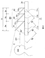
以下、この発明の一実施の形態を、図面を参照して説明する。図1および図2はこの発明の一実施の形態に係る3次元映像表示装置を構成する要素の位置関係を示す斜視図および側面図である。
図1および図2を参照して、3次元映像表示装置の主要な構成要素は、2次元映像表示装置70と2次元映像表示装置70の上に設けられたミラー装置80である。ミラー装置80の主要な構成要素は2枚の平板のハーフミラー81,82と1枚の平板のフルミラー83である。図1および図2においては、ミラー装置80はハーフミラー81,82とフルミラー83だけが示されており、ミラーを所定の位置に固定するための構成要素は示していない。図2においてハーフミラー81,82とフルミラー83は2次元映像表示装置70の画面71a,71b,71cに表示された映像を反射し、虚像81a,82a,83aを生成する。
図2に示すようにハーフミラー81,82とフルミラー83とは画面71に対して、所定間隔かつ所定角度に傾斜させて配置される。ハーフミラー81,82およびフルミラー83は画面71の上に一定角度で傾斜させ、かつすべてのハーフミラー81,82とフルミラー83の面同士が平行になるように配置する。ハーフミラー81,82およびフルミラー83は観賞者200の側に約45°傾斜させて配置することが好ましい。
2次元映像表示装置70は、薄型テレビや携帯電話、スマートフォンなどに用いられる、液晶ディスプレイ、プラズマディスプレイ、LEDディスプレイ、有機ELディスプレイなどを示すが、ディスプレイ部分を含んだ薄型テレビ、携帯電話、携帯ゲームプレーヤー、タッチ式タブレットなどの表示器を有する装置を含む。
図2に示すように、ハーフミラー81,82とフルミラー83の高さは観賞者200から見て奥に行くにつれて低くなるように観賞領域Vが楔状である(即ちミラーの高さが徐々に低くなっている)。前後のハーフミラー81,82、あるいはフルミラー83の高さの比は同じでその範囲は1:0.65~1:0.95とする。
また、前後のハーフミラー81,82、あるいはフルミラー83の高さの比はHa: Hb=1:0.79かつHb: Hc=1:0.79とするのが好ましい。
また、前後のハーフミラー81,82、あるいはフルミラー83の高さの比はHa: Hb=1:0.79かつHb: Hc=1:0.79とするのが好ましい。
そのため、画面71の奥行きDに対して、ハーフミラー81の映像領域71aの長さDaは0.41D、ハーフミラー82の映像領域71bの長さDbは0.33D、フルミラー83の映像領域71cの長さDcは0.26Dとなり、ハーフミラー81,82とフルミラー83の高さHa, Hb, Hcの高さはそれぞれDa, Db, Dcの1.4倍になる。図1において、ハーフミラー81,82とフルミラー83の幅Wmは画面71の幅Wよりも若干長い。
ハーフミラー81の下の映像領域71aの虚像81a、ハーフミラー82の下の映像領域71bの虚像82a、フルミラー83の下の映像領域71cの虚像83aが観賞者200の視線方向201の奥行き位置に重なって見え、3次元映像として見える。
この実施の形態においては従来では用いられなかった反射率の高いハーフミラーを使用することで、より明るい3次元映像を得ることができる。具体的には観賞者200からみて最も手前のハーフミラー81の可視光の透過率:反射率を67:33~60:40の範囲とし、次のハーフミラー82の可視光の透過率:反射率を50:50~55:45とし、最も奥のフルミラー83の可視光の反射率を100%~80%とすることで、観賞者からはすべての虚像81a,81b,81cがほぼ同じ明るさに見え、室内で照明を点けた状態でも十分な明るさの映像が得られる。その結果、3次元映像を室内の照明を点けた明るさでの観賞が可能になる。
なお、ミラー装置を構成する各ミラーの透過率:反射率の好ましい組み合わせとしては、
ハーフミラー81が67:33、ハーフミラー82が50:50、フルミラー83の反射率が100%としてもよい。これはフルミラー83の反射性能が高い場合を想定している。
また別の好ましい組み合わせは、ハーフミラー81が69:31、ハーフミラー82が55:45、フルミラー83の反射率が80%である。これはフルミラー83の反射性能がやや劣った場合を想定している。
ハーフミラー81が67:33、ハーフミラー82が50:50、フルミラー83の反射率が100%としてもよい。これはフルミラー83の反射性能が高い場合を想定している。
また別の好ましい組み合わせは、ハーフミラー81が69:31、ハーフミラー82が55:45、フルミラー83の反射率が80%である。これはフルミラー83の反射性能がやや劣った場合を想定している。
さらに別の好ましい組み合わせは、ハーフミラー81が60:40、ハーフミラー82が50:50、フルミラー83の反射率が80%である。上記2つの組合せは理論的な計算に基づく値であるが、この値は実験的に得られた値である。
この時のゴーストを軽減するためにハーフミラー81,82およびフルミラー83の反射物質のコーティング面は観賞者200の側になるように配置する。
この時のゴーストを軽減するためにハーフミラー81,82およびフルミラー83の反射物質のコーティング面は観賞者200の側になるように配置する。
次に、図1および図2に示したハーフミラー81,82とフルミラー83と2次元映像表示装置70とを所定の位置に配置、固定するための具体的な実施の形態について説明する。なお、ハーフミラー81,82とフルミラー83の基本的な比例寸法や透過率、反射率は同じである。
(1)第1実施形態
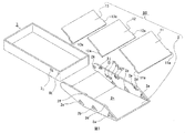
図3は本発明の第1実施形態に係る3次元映像表示装置の全体構成を示す分解斜視図である。ただしこの図の中には2次元映像表示装置70は含まれていない。図3を参照して、ミラー装置80は、ミラーケース2と、ハーフミラー11,12と、フルミラー13から構成される。ミラー装置80は本体ケース3と合体できる。
図3は本発明の第1実施形態に係る3次元映像表示装置の全体構成を示す分解斜視図である。ただしこの図の中には2次元映像表示装置70は含まれていない。図3を参照して、ミラー装置80は、ミラーケース2と、ハーフミラー11,12と、フルミラー13から構成される。ミラー装置80は本体ケース3と合体できる。
本体ケース3は2次元映像表示装置70が隙間なく入る容器の形を呈しており、ミラーケース2と合体させるための一対の軸受け穴3kとミラーケース2の位置を安定させるための一対の谷型の突起3jを備えている。本体ケース3の容器は、2次元映像表示装置70を正しく収容することができる程の幅、高さ、奥行き長さを有している。2次元映像表示装置70がこの容器に適正に収容されたときには、2次元映像表示装置70の映像領域71a、71b、71cが、ハーフミラー11,12、フルミラー13に適正に位置合わせされたことを表している。
ミラーケース2はハーフミラー11,12とフルミラー13を所定の位置に固定するものであり、本体ケース3と合体させる機能を持っている。ミラーケース2には、ハーフミラー11,12とフルミラー13を固定するための一対の略扇形の穴(軸穴)2a,2b,2cと一対のストッパー2d,2f,2h、および一対の爪2e,2g,2iが両側に具わっており、本体ケースとの合体のための一対のピボット2kとミラーケース2と本体ケース3の位置を安定させるための一対の山型の突起2jが具わっている。本体ケース3およびミラーケース2の材質はポリプロピレン、ポリカーボネート、ABS樹脂、スチロール樹脂、硬質塩化ビニールなどの弾性を持つ合成樹脂が好ましい。
ハーフミラー11,12とフルミラー13はミラーケース2にある略扇形穴(軸穴)2a,2b,2cに差し込めるよう、矩形の軸11a,12a,13aをその一辺の両側に持つ略長方形の形状を呈している。ハーフミラー11,12、フルミラー13の厚さは画面71の対角線長さが3.5インチ程度の場合1mm~2mmが好ましい。
なお、図示の例では、ハーフミラー11,12及びフルミラー13をミラーケース2に取り付ける場合は、矩形の軸11a,12a,13aを略扇形穴(軸穴)2a,2b,2cに差し込む構造としているが、これに限定されない。例えば、軸11a,12a,13aは矩形でなく、先の尖った円錐形状又は多角錐形状でもよく、それらと係合する軸穴2a,2b,2cは略扇形穴形状でなく、単なる微小の穴又は凹部でもよい。
なお、図示の例では、ハーフミラー11,12及びフルミラー13をミラーケース2に取り付ける場合は、矩形の軸11a,12a,13aを略扇形穴(軸穴)2a,2b,2cに差し込む構造としているが、これに限定されない。例えば、軸11a,12a,13aは矩形でなく、先の尖った円錐形状又は多角錐形状でもよく、それらと係合する軸穴2a,2b,2cは略扇形穴形状でなく、単なる微小の穴又は凹部でもよい。
画面71が10インチ程度の場合2mm~3mmが好ましい。画面71が30インチ程度の場合3mm~5mmが好ましい。ハーフミラー11,12およびフルミラー13はガラスまたはアクリル、硬質塩化ビニール、ポリカーボネート製であることが好ましい。色はできるだけ透明に近いものが好ましい。ハーフミラー11,12の可視光の透過率や反射率は上記したとおりであり、ハーフミラー11,12は可視光の吸収率を少なく抑えたいため誘電体多層膜コーティングによるハーフミラーが好ましい。フルミラー13は誘電体多層膜コーティングによるものが好ましいが、金属蒸着膜によるインコーネルコーティングのものでもかまわない。
図4は本体ケース3に2次元映像表示装置70を収容し、ミラー装置80と本体ケース3とが合体した状態を示す。ミラー装置80はミラーケース2の略扇形の穴2a,2b,2cにハーフミラー11,12とフルミラー13の軸がそれぞれの差し込まれることで組み立てられる。
また、本体ケース3の軸受け穴3kにミラーケース2のピボット2kを差し込むことでミラー装置80と本体ケース3は合体できる(図12(D)参照)。図4の状態では、画面71が全部見えているため、画面71を通常に観賞できるが、ハーフミラー11,12とフルミラー13が画面71に対して所定の位置にはないので3次元映像の観賞はできない。
なお、本体ケース3とミラーケース2の合体は、本体ケース3の軸受け穴3kにミラーケース2のピボット2kを差し込む構造に限定されない。例えば、逆の構造として、本体ケース3に設けたピボットを、ミラーケース2に設けた軸受け穴に合体させる機構でもよい。要するに、ミラーケース2が本体ケース3に回転可能に取り付けられる機構であればよい。
図5はハーフミラー11が軸を中心に回転する状態を示す図である。図5(A)はハーフミラー11の斜視図であり、図5(B)は側面図である。図5を参照して、ハーフミラー11の軸11aは外部へ突出した矩形であり、長さはdであり、幅はwである。長さdは略扇形の軸受け穴2aの径と等しい。両側に矩形の軸11aを持つハーフミラー11は両側から略扇形の軸受け穴2a(図3参照)によって挟むことで抜け落ちることなく、略扇形の扇頂角αの範囲で回転軸101を中心に回転できるように固定される。すなわち、ハーフミラー11は点線のハーフミラー11で示す位置まで回転軸がぶれることなく回転が可能となる。通常回転部分の軸は細い形状となるが、ハーフミラー11がガラスや合成樹脂で製作されることを考慮して、軸11aを矩形にして強度を高め、軸が欠け落ちる危険性を軽減している。同様の仕組みによってハーフミラー12とフルミラー13もそれぞれ略扇形の軸受け穴2b,2cによって回転を可能にしながら固定される。
図6および図7はハーフミラー11,12、およびフルミラー13の軸11a,12a,13aの強度を説明した図である。図6(A)と(B)はそれぞれd1、d2が異なる形状の軸を示す図である。軸11a,12a,13aはすべて図6(C)の100のような形状をしている。このような形状の場合、荷重に対する応力集中はコーナー部C1,C2によく発生する。底辺Bを固定し、Pの位置に荷重をかけた条件で有限要素法の平面応力解析をすると、コーナー部C1,C2に最大主応力の応力集中が発生する。
通常回転部分の軸は細く、たとえば図6(A)に示すように幅w:長さd1=1:1のような形状の場合のコーナー部の最大主応力σaが1.0であったとする。一方図6(B)に示すようにw:d2=1:5として軸の形状の長さが長い矩形にすることで、コーナー部の最大主応力σbは約0.3となる。
ハーフミラー11,12、およびフルミラー13の材質はガラスや合成樹脂であるため、軸の欠け落ちを防止するためには、できるだけ応力集中箇所の応力を軽減するべきである。そこで、この実施の形態においては、軸の幅wに対する長さd2の比を大きくすることで、コーナー部の応力を軽減している。なお、幅w:長さd2の比は1:4以上が好ましく、1:5とすることによって、1:1の場合と比べてコーナー部の応力を約3分の1に軽減できる。
図7は、軸の形状の変更例を示す図である。図7に示すようにハーフミラー11,12、およびフルミラー13の軸が形成されているコーナー部C1とC2(図6(C)参照)にRをつけることで、さらに応力を分散させることができる。この場合Rの半径rはwの3分の1~4分の1にすることが好ましい。
ミラー装置80の回転移動について説明する。
図4のミラー装置80において、ハーフミラー11はミラーケース2に具わっているストッパー2dおよび爪2e(図9(A)、(B)、図3参照)に入る状態にあるため回転を許されない状態にある。ハーフミラー12およびフルミラー13も同様にストッパー2f,2h、および爪2g,2iによって回転を許されない状態にある。(図9(A)参照)。
図4のミラー装置80において、ハーフミラー11はミラーケース2に具わっているストッパー2dおよび爪2e(図9(A)、(B)、図3参照)に入る状態にあるため回転を許されない状態にある。ハーフミラー12およびフルミラー13も同様にストッパー2f,2h、および爪2g,2iによって回転を許されない状態にある。(図9(A)参照)。
図4の状態からミラー装置80を、ピボット2kを中心に回転させ2次元映像表示装置70が入った本体ケース3の上に被せた状態を図8、図9に示す。図9(A)は3次元映像表示装置の3次元映像の観賞時の一部断面図であり、図9(B)は図9(A)において、矢印B-Bで示す部分の断面図であり、図9(C)は図9(A)において、矢印C-Cで示す部分の断面図である。図9(A)に示す状態で画面71に対してハーフミラー11,12とフルミラー13が所定の位置にあり、この実施の形態の3次元映像の観賞時の状態となる。本体ケース3と軸受け穴3k、ミラーケース2とピボット2kおよび略扇形の穴2a,2b,2cとストッパー2d,2f,2h、爪2e,2g,2iは、この状態で画面71に対してハーフミラー11,12とフルミラー13が所定の位置になるよう配置されている。略扇形穴2a,2b,2cの扇頂角はそれぞれ約28度、約23度、約15度となる。
図8および図9の3次元映像の観賞時の状態において、図9(C)に示すように、ミラーケース2に具わっている山型の突起2jは本体ケース3の谷型の突起3jの谷の部分に入っている。そのため。ミラー装置80と本体ケース3の位置はある程度固定される。またミラーケース2と本体ケース3はポリプロピレンなどの弾性のある合成樹脂でできているため、ある程度の力で山型の突起2jは谷型の突起3jから外れてミラーケース2を回転させて図4の状態にすることができる。図4の状態から図8、図9の状態にもすることも同様の理由から可能である。このようにミラー装置80を簡単に回転させて動かすことが可能なため、3次元映像を観賞する状態と2次元映像表示装置70の画面71を通常の観賞する状態とを簡単に切り替えることができる。また画面71がタッチパネル付の場合は図4の状態では画面を触ることもできる。
以上のように、この実施の形態においては、2次元映像表示装置の装着後もミラー装置80の部分だけを2次元映像表示装置70の画面から引き離すことで、2次元映像と3次元映像を瞬時にかつ簡単な操作で切り替えて見ることが可能になる。
ミラー装置80の折り畳みについて説明する。
図10はミラーケース2内において図4の状態からミラーを折り畳んだ状態を示す。図10に示すように、ハーフミラー11は力P1を加えると、爪2eを乗り越えてミラーケース2の底部2nに折り畳める(図3参照)。ハーフミラー12とフルミラー13も同様に折り畳むことができる。図11と図12は図10の状態のミラーケース2を本体ケース3に被せた状態を示す。図9の3次元映像の観賞時と違い、ハーフミラー11,12とフルミラー13はミラーケース2の中に折り重なり、ミラー装置80は本体ケース3と2次元映像表示装置70に接近した状態で折り畳まれている。図9の観賞時と比較して全体の体積が削減されていることがわかる。
図10はミラーケース2内において図4の状態からミラーを折り畳んだ状態を示す。図10に示すように、ハーフミラー11は力P1を加えると、爪2eを乗り越えてミラーケース2の底部2nに折り畳める(図3参照)。ハーフミラー12とフルミラー13も同様に折り畳むことができる。図11と図12は図10の状態のミラーケース2を本体ケース3に被せた状態を示す。図9の3次元映像の観賞時と違い、ハーフミラー11,12とフルミラー13はミラーケース2の中に折り重なり、ミラー装置80は本体ケース3と2次元映像表示装置70に接近した状態で折り畳まれている。図9の観賞時と比較して全体の体積が削減されていることがわかる。
図12(A)は折り畳み時の一部断面図であり、図12(B)は図12(A)において、矢印B-Bで示す部分の断面図であり、図12(C)は図12(A)において、矢印C-Cで示す部分の断面図であり、図12(D)は図12(A)において、矢印D-Dで示す部分の断面図である。この実施の形態では図12(B)に示すようにハーフミラー11はストッパー2dと爪2eからはずれている。また図12(C)に示すように山型の突起2jは谷型の突起3jから外れている。
以上のように、この実施の形態によれば、かさばるハーフミラーの部分を折り畳んでコンパクトにできる構造をとることで、収納や持運びに適した3次元映像表示装置を提供することができる。
図13にハーフミラー11,12およびフルミラー13がミラーケース2の中に折り畳まれる仕組みを示す。図13(A)は仮にミラーケース2の底部2n’に折れがなく平板であった場合、ハーフミラー11,12とフルミラー13をミラーケースの中に折り畳み、さらにミラーケース2を本体ケース3に被せようと試みた状態を示す図である。このとき画面71からのミラーケース2の折り畳み時の底部2n’の高さh1をできるだけ低くすることで折り畳んだ状態での体積を少なくできる。ところがこれを実現しようとすると、ミラーケース2と本体ケース3をつなぐ回転軸k’は本体ケース3から離れた位置に存在しなければならず、両者の合体ができない。また図13(B)のように両者が合体できるよう、本体ケース3の中に回転軸kを配置した場合、底部2n’と画面71の折り畳み時の高さh2は3次元映像の観賞時の高さhmaxの約40%になる。このときミラーケース2の端部2w’が最高高さとなり、この高さが折り畳み時の高さh2になっている。
図13(C)はミラーケース2の底部2nをフルミラー13の上端部付近2vで折った場合を示す。この場合折曲げ角度θを約19度とすることで、ミラーケース2の端部2wは画面71に接近するため、ミラーケース2の2vの位置が最高高さとなり折り畳み時の高さh3は観賞時の高さhmaxの約30%にすることができる。また最高高さとなる位置2vがミラーケース2の底部2nの中央付近にくるため、図13(B)と比較して中央が膨らんだ角張らない形状となり、持運ぶのに適している。このようにミラーケース2の底部2nを2v付近で折っても、フルミラー13が収納されるスペースがあるため、フルミラー13の折り畳みにも影響はない。
図14はミラーケースの上面を示す斜視図である。図14に示すようにミラーケース2の底部にはU字型の切込み2p,2q,2rがある。U字型の切込2pの内側部分2sに指や手などの力P2を加えて合成樹脂の弾性で切込み内部をハーフミラー11側にたわませることができる。この作業を図10の状態で行うと2sの部分がハーフミラー11に当たって押し出すことになり、折り畳まれた状態からストッパー2d、爪2eの間に挟まる位置まで回転させることができる。こうすることで直接ハーフミラー11に指や手を触れることなくハーフミラー11を回転させることができる。ハーフミラー12とフルミラー13も同様に2t,2uの部分に力を加えることにより指などで直接触れることなく回転させることができる。
図15は本体ケース3とは別の形態の本体ケース4を示す斜視図である。本体ケース4は2次元映像表示装置70の端部だけを隙間なく覆う形状となっている。図16は本体ケース4に2次元映像表示装置70を入れ、ミラーケース2を合体させた状態の断面図である。本体ケース4も弾性を持つ合成樹脂で作ることが好ましい。また本体ケース4と2次元映像表示装置70とは摩擦力によって容易に外れない。軸受け穴4kと谷型の突起4jは、本体ケース3の軸受け穴3kと谷型の突起3jと同様の機能を果たす。
以上のように、この実施の形態においては、液晶ディスプレイなどの2次元映像表示装置70にハーフミラーなどからなるミラー装置を簡単に着脱でき、ミラー装置は折り畳ためてコンパクトにできる。観賞者は3次元映像装置を容易に持ち運び、2次元映像表示装置70をそれに装着することで、簡単に3次元映像を楽しむことができる。
(2)第2実施形態
次に、この発明の第2実施形態について説明する。図17は本発明の第2実施形態に係る3次元映像表示装置の構成部品を示す図である。ただしこの図の中には2次元映像表示装置70は含まれていない。図17に示すように、ミラー装置50はミラーケース5a、ハーフミラー11,12、フルミラー13および本体ケース5bから構成される。ミラーケース5aと本体ケース5bはヒンジ部5fによってつながっているため、ポリプロピレンなどの耐ヒンジ特性の高い合成樹脂による一体成型で作ることが好ましい。
次に、この発明の第2実施形態について説明する。図17は本発明の第2実施形態に係る3次元映像表示装置の構成部品を示す図である。ただしこの図の中には2次元映像表示装置70は含まれていない。図17に示すように、ミラー装置50はミラーケース5a、ハーフミラー11,12、フルミラー13および本体ケース5bから構成される。ミラーケース5aと本体ケース5bはヒンジ部5fによってつながっているため、ポリプロピレンなどの耐ヒンジ特性の高い合成樹脂による一体成型で作ることが好ましい。
ミラーケース5aにはハーフミラー11,12、フルミラー13を装着して固定するための溝5c,5d,5eがある。ハーフミラー11,12、フルミラー13の厚さと材質、および透過率、反射率は実施形態1と同じであるが、形はすべて長方形である。
本体ケース5bは2次元映像表示装置70の先端を隙間なく覆って支持する形状となっている。
本体ケース5bは2次元映像表示装置70の先端を隙間なく覆って支持する形状となっている。
図18、図19はミラーケース5aにハーフミラー11,12、フルミラー13を固定してミラー装置50が形成され、本体ケース5bに2次元映像表示装置70を入れた状態を示す図である。これは2次元映像表示装置70の画面71を通常の観賞する状態である。
図20、図21はミラーケース5aをヒンジ5fを軸に回転させて画面71に被せた状態を示す図である。この状態ではハーフミラー11,12とフルミラー13が画面71に対して所定の位置に来るため、3次元映像を観賞することができる。このようにミラー装置50を簡単に回転して動かすことが可能なため、3次元映像を観賞する状態と2次元映像表示装置70の画面71を通常の観賞する状態とを簡単に切り替えることができる。また画面71がタッチパネル付の場合は図18、図19の状態では画面を触ることもできる。
第2実施形態では第1実施形態のようにミラー装置50の部分を折り畳んで体積を削減することはできない。しかしながら、第2実施形態は第1実施形態よりも部品数が少なく、部品の形状も簡単である。そのため、第1実施形態よりも製作コストを軽減することが可能である。
なお、第2実施形態は種々変形して実施することができる。例えば、上記実施形態では、ミラーケース5aはヒンジ5fを軸に回転可能な構造としたが、ヒンジ5fを設けずに、ミラーケース5aと本体ケース5bを一体的に固定した構成としてもよい。2次元映像表示装置70を本体ケース5bに装着するには、2次元映像表示装置70を本体ケース5bの前方から挿入して装着することができる。
以上のように、第2実施形態においては、液晶ディスプレイなどの2次元映像表示装置70にハーフミラー等からなるミラー装置を簡単に着脱でき、3次元映像を楽しむことが可能になる。
(3)第3実施形態
次に、図22以降を参照しながら、3次元映像表示装置の具体的な構成例について説明する。なお、ハーフミラーやフルミラーの基本的な寸法比等は図1乃至図2と同じである。
次に、図22以降を参照しながら、3次元映像表示装置の具体的な構成例について説明する。なお、ハーフミラーやフルミラーの基本的な寸法比等は図1乃至図2と同じである。
図22は、3次元映像が観賞できる状態の3次元映像表示装置の斜視図、図23はミラー装置を開いた状態における2次元映像表示装置70の画面で2次元映像が観賞できる状態の3次元映像表示装置の斜視図、図24はミラー装置の分解斜視図、図25は、ミラー装置を閉じた状態の3次元映像表示装置の斜視図、図26はミラー装置の斜視図を示す。
図25に示すように、3次元映像表示装置は、ミラー装置90と本体ケース3から構成される。図22に示すように本体ケース3は略箱型であり、その中に2次元映像表示装置70が収容される。2次元映像表示装置70は例えばスマートフォンである。ミラー装置90は、複数のミラー(本例では3枚ミラー)が奥行き方向に所定の間隔で平行に配列して実装される、略箱型のミラーケース2を備え、このミラーケース2、その軸2kが本体ケース3の後端部の軸受け3k(図27、図28参照)に支持されて回転可能である。図23はミラーケース2を回転させて、本体ケース3から完全に開いた状態を示す。また、図25に示すように、ミラーケース2が本体ケース3に閉じた状態では、3次元映像表示装置は1つの箱型となるので、コンパクトとなり、バッグへの収納や持ち運びが容易で便利となる。
図22乃至図27に示すように、本体ケース3はその周囲をフランジ(高さの低い側壁)3iで囲い、中央にはフランジ3iによって囲まれた収容部3mが設けられる。この収容部3mに、2次元映像を表示する画面71を備えた2次元映像表示装置70が、着脱自在に装着される。手前の左右には、2次元映像表示装置70が手前側に移動して脱落することを防止するための、1対のガイド壁3bが設けられる。なお、本体ケース3の詳細は、図27~図28を参照して後述する。
次に、ミラー装置90の構成について詳しく説明する。
図23を参照するに、ミラーケース2には、前方から順に2枚のハーフミラー11、12及び1枚のフルミラー13が実装される。2枚の四辺形のハーフミラー11、12は四辺形のミラーフレーム21、22にはめ込むようにして取り付けられ、四辺形のフルミラー13は同じく四辺形のミラーフレーム23に取り付けられる。複数のミラー11,12,13の四辺形状の幅(図示の例では長辺)は同じであるが、他の一辺(短辺)は奥に行く(鑑賞者から遠く)につれて、短くなる。ここで、ミラーケース2と、ミラーフレーム21,22,23はいずれも弾性のある合成樹脂、例えばABS、ポリカーボネート、ポリプロピレンなどの材料で形成するのが好ましい。
図23を参照するに、ミラーケース2には、前方から順に2枚のハーフミラー11、12及び1枚のフルミラー13が実装される。2枚の四辺形のハーフミラー11、12は四辺形のミラーフレーム21、22にはめ込むようにして取り付けられ、四辺形のフルミラー13は同じく四辺形のミラーフレーム23に取り付けられる。複数のミラー11,12,13の四辺形状の幅(図示の例では長辺)は同じであるが、他の一辺(短辺)は奥に行く(鑑賞者から遠く)につれて、短くなる。ここで、ミラーケース2と、ミラーフレーム21,22,23はいずれも弾性のある合成樹脂、例えばABS、ポリカーボネート、ポリプロピレンなどの材料で形成するのが好ましい。
次に、図24の分解斜視図を参照して、ミラー装置90の組立て構造について説明する。
ハーフミラー11,12はそれぞれミラーフレーム21,22にはめ込まれ、フルミラー13はミラーケース2の一部を形成するミラーフレーム23にはめ込まれて取り付けられる。ミラーフレーム21にはそれぞれ一対の軸21aがある。片方の軸21aにねじりコイルバネ41を係合した状態で、ミラーケース2に設けられた1対の軸受け部20aに取り付けられる。ハーフミラー12をはめ込んだミラーフレーム22も同様に、ねじりコイルバネ42を係合した状態で、ミラーケース2に設けられた1対の軸受け部20bに取り付けられる。なお、軸受け部20a,20bは弾性のある合成樹脂で形成されているので、ある程度の変形が可能であり、ミラーフレーム21,22の軸21a,22aをはめ込むことが可能である。
ハーフミラー11,12はそれぞれミラーフレーム21,22にはめ込まれ、フルミラー13はミラーケース2の一部を形成するミラーフレーム23にはめ込まれて取り付けられる。ミラーフレーム21にはそれぞれ一対の軸21aがある。片方の軸21aにねじりコイルバネ41を係合した状態で、ミラーケース2に設けられた1対の軸受け部20aに取り付けられる。ハーフミラー12をはめ込んだミラーフレーム22も同様に、ねじりコイルバネ42を係合した状態で、ミラーケース2に設けられた1対の軸受け部20bに取り付けられる。なお、軸受け部20a,20bは弾性のある合成樹脂で形成されているので、ある程度の変形が可能であり、ミラーフレーム21,22の軸21a,22aをはめ込むことが可能である。
このようにして、ハーフミラー11,12を取り付けたミラーフレーム21,22は、ねじりコイルバネ41,42の作用力によってミラーフレーム21,22を軸21a,22aを中心にして開放する方向に回転させる力が働き、ミラーフレームの先端21d,22dを2次元映像表示装置70の画面71の表面に密着させる(詳しくは図29、図31を参照)。一方、フルミラー13を取り付けたミラーフレーム23はミラーケース2と一体成型されていて、回転はしない。この状態で、ミラーフレーム23の先端20dは、ミラーフレームの先端21d,22dと同じように、画面71に接する面(図29のS)を形成する。ミラーフレーム21,22は、ハーフミラー11,12の先端が直接画面71に接触して画面を傷つけるのを防止する役目も果たす。
図26は、ミラー装置90の組立が完成した状態の斜視図を示す。
ミラーケース2の後端には1対の軸2kが設けられ、この軸2kが本体ケース3に設けられた1対の軸受け3kに係合して、ミラー装置90と本体ケース3が合体した組立体を構成する。ミラー装置90乃至ミラーケース2は、本体ケース3に対して軸2kを中心にして回転可能である。
ミラーケース2の後端には1対の軸2kが設けられ、この軸2kが本体ケース3に設けられた1対の軸受け3kに係合して、ミラー装置90と本体ケース3が合体した組立体を構成する。ミラー装置90乃至ミラーケース2は、本体ケース3に対して軸2kを中心にして回転可能である。
図22は、2次元映像表示装置70を本体ケース3の収容部3mに収容した状態で、2次元映像表示装置70の画面71に表示された2次元映像を、ミラー21~23で反射させて、観賞者に3次元映像を表示する状態を示す。また、図23は、同じく2次元映像表示装置70を本体ケース3の収容部3mに収容した状態であって、ミラー装置90を回転させて画面71を開放させた状態で、2次元映像表示装置70の画面71に表示される通常の2次元映像を観賞することができる状態を示す。この状態では3次元映像は観賞できない。なお、スマートフォンのような画面71がタッチパネルの機能を備えている場合は、2次元映像を観賞中にも指などで画面71を自在に触ることができる。
図29はミラー装置の側断面図である。
図29を参照して、ミラーフレーム21,22の動作、作用について説明する。
ミラーフレーム21は、軸21aを中心軸として一定の範囲で回転可能な状態にある。しかし、ねじりコイルバネ41の力によってミラーフレーム21に回転力が加わり、端部21bがストッパー20eに接する状態にある。この状態では、ミラーフレーム21に何も力を加えない場合は、ミラーフレーム21はミラーケース2に対してこの位置を維持し続ける。またミラーフレーム21に一定以上の力を加えられると(即ちミラーケースを本体ケース3に閉じるとき)、ねじりコイルバネ41の反発力が負けて、ミラーフレーム21は端部21dの部分がミラーケース2にむけて回動する。
ミラーフレーム22も、ミラーフレーム21と同様の状態にある。ただしミラーフレーム22の場合は、端部22bがミラーケース2の底面20gに接する状態にある。ミラーフレーム22も一定以上の力が加えられると、端部22dの部分がミラーケース2に向けて回動する。なお、ねじりコイルバネ41,42は軸21a,22a以外の箇所に係合させてもよい。
図29の状態で、ミラーフレーム21の端部21d、ミラーフレーム22の端部22d、およびミラーフレーム23の端部20dは同一平面S(即ち画面71)にある。さらに、ミラーケース2の一対の軸2kの中心も同一平面S上にある。また、ハーフミラー11,12およびフルミラー13の反射面は平面Sに対して45°を維持して並行状態になっている。
ミラーフレーム21の端部21dが、ハーフミラー11の反射面に対して45°の角度となっている理由は、端部21dが2次元映像表示装置70の画面71に接触した際に、2次元映像表示装置70の画面71に対してできるだけ広い面積で接することで、画面71をガラス製のハーフミラー11が傷付けないためである。
図27及び図28、図30を参照して、本体ケース3の構成について詳しく説明する。
本体ケース3の奥部には、2次元映像表示装置70の先頭部が挿入されるソケット部3eが設けられ、更にソケット部3eの対向する本体ケース3の底部には、その一部が切り欠かれて、ソケット部3eの内部に曲げて延伸した板バネ部3aが設けられる。これらの構成部位は、本体ケース3と一体形成された合成樹脂製である。
本体ケース3の奥部には、2次元映像表示装置70の先頭部が挿入されるソケット部3eが設けられ、更にソケット部3eの対向する本体ケース3の底部には、その一部が切り欠かれて、ソケット部3eの内部に曲げて延伸した板バネ部3aが設けられる。これらの構成部位は、本体ケース3と一体形成された合成樹脂製である。
ソケット部3eの内部の左右には、例えばスポンジやゴム等から成る一対の軟質部材51が配設される。図30に軟質部材51の配設位置を示す。なお、図30の(A)は縦断面図、(B)は、平面図、(C)は横断面図である。ソケット部3eの内部に一対の軟質部材51を配設する理由は、幅の異なる複数種の2次元映像表示装置70を受け入れて、この軟質部材51でその幅の違いを吸収するためである。
図30(A)に示すように、本体ケース3の底部に板バネ部3aを設ける理由は、板バネ部3aと本体ケース3のソケット部3eの内側との間に、高さ異なる複数種の2次元映像表示装置70を受け入れて、この板バネ部3aの弾性力によって画面71が基準面3gに常に接した状態になる。また、板バネ3aの圧力によって、2次元映像表示装置70がソケット部3eから容易に抜けないように、それを保持している。
本体ケース3の後端部には、ミラー装置90の軸2kを回転自在に取り付けるための軸受け3kが設けられる。図30(A)に示すように、軸受3kは基準面3gと同一平面R上にある。また、図29の各ミラーフレームの端部21d,22d,20dおよび軸2kは同一平面S上にある。本体ケース3に対してミラー装置90が軸2kを中心に回転するとき、この平面Sも同時に回転し、図31(A)に示すように平面Rと平面Sとが合致する。2次元映像表示装置70の画面71は基準面3gに接しているため、各ミラーフレームの端部21d,22d,20dが画面71に密着することになる。このように、ハーフミラー11,12とフルミラー13が画面71に対して高い精度で位置付けられた状態で、観賞者に3次元映像を表示することができる。
図31は、本体ケース3に2次元映像表示装置70を収容して、ミラー装置90を用いて3次元映像が観賞できる状態における3次元映像表示装置の三方向から見た断面図である。
本体ケース3のソケット部3eに2次元映像表示装置70を挿入すると、一対の軟質部材51は2次元映像表示装置70の幅形状に合わせて収縮し、一定の圧力で2次元映像表示装置70を押さえつける。軟質部材51には一定の摩擦があるので、本体ケース3のソケット部3eから2次元映像表示装置70が容易に抜けることを防止する。
本体ケース3のソケット部3eに2次元映像表示装置70を挿入すると、一対の軟質部材51は2次元映像表示装置70の幅形状に合わせて収縮し、一定の圧力で2次元映像表示装置70を押さえつける。軟質部材51には一定の摩擦があるので、本体ケース3のソケット部3eから2次元映像表示装置70が容易に抜けることを防止する。
また、本体ケース3の手前に設けられた一対の略L字型の壁3b(図30乃至図31)によって、2次元映像表示装置70が本体ケース3から容易に抜けることを防止している。ここで、壁3bは、2次元映像表示装置70幅及び長さよりも若干大きいサイズを許容する位置に設置されている。
図31(A)、(C)において、本体ケース3の板バネ3aは一定の圧力で2次元映像表示装置70を基準面3gに対して押し付けており、画面71の端部は常に基準面3gと接触した状態にある。
また、図31(A)に示すように、3つのミラーフレーム21,22,23が、3次元映像を表示する状態にあるときでも、ミラーフレーム23とミラーケース2は一体形成され、端部20dと、軸2kと、ミラーフレーム23とミラーケース2の合体した頂点P(角度βを維持して)は3点支持の状態にあり、強固であるので、ミラーケース2は並行配置状態にあるミラーフレーム21,22に対して外力を伝えない状態にある。このため、ミラーケース2の外部から外力が加わったとしても、並行配置状態で3次元映像の表示状態にあるミラーフレーム21,22が折り畳まれることが防止できる。
図32は、図31に示した2次元映像表示装置70と異なる大きさの2次元映像表示装置60を、本体ケース3に装着した場合を示す。
図31の2次元映像表示装置70の各寸法Ws1、Ds1、Ts1と比べて、図32の2次元映像表示装置60の各寸法Ws2、Ds2、Ts2は全て若干小さい例である。図32(B),(C)に示すように、軟質部材51は2次元映像表示装置60をその幅方向から十分な圧力で保持している。また、本体ケース3の板バネ3aは一定の圧力で2次元映像表示装置60を基準面3gに対して押し付けており、画面81の端部は常に基準面3gと接触した状態になる。軟質部材51には一定の摩擦があるため、本体ケース3のソケット部3eから2次元映像表示装置60は容易に抜けることを防止している。
図31の2次元映像表示装置70の各寸法Ws1、Ds1、Ts1と比べて、図32の2次元映像表示装置60の各寸法Ws2、Ds2、Ts2は全て若干小さい例である。図32(B),(C)に示すように、軟質部材51は2次元映像表示装置60をその幅方向から十分な圧力で保持している。また、本体ケース3の板バネ3aは一定の圧力で2次元映像表示装置60を基準面3gに対して押し付けており、画面81の端部は常に基準面3gと接触した状態になる。軟質部材51には一定の摩擦があるため、本体ケース3のソケット部3eから2次元映像表示装置60は容易に抜けることを防止している。
また、図30及び図31に示す、一対の略L字型の壁3cによって、2次元映像表示装置60が本体ケース3から容易に抜けることを防止している。なお壁3cは2次元映像表示装置60よりも若干大きいサイズを許容する位置に設置されている。更にガイド壁3bと壁3cには段差があるため、大きさの異なる2種類の2次元映像表示装置70、60の両方を受け入れることができる。
図31(A)の例では、本体ケース3の底部3hと画面71は平行であったが、図32(A)の例では、2次元映像表示装置60の厚さTs2が薄いため、画面81は底部3hとわずかな角度θを成している。
図32のように、画面81が底部3hに対してわずかな角度θを成していても、ミラーフレーム21,22の端部21d、22d、ミラーフレーム23のケース端部20d、ミラーケース2の軸2kは同一平面上にあり、画面81が基準面3gとほぼ接しているため、軸受け3kは画面81上にある。このように、端部21d、22d、および端部20dが形成する平面S(図29)は画面81と同一面にあることになり、ハーフミラー11,12およびフルミラー13が画面81に対して高い精度で所定の位置に配置されることになる。
このように本実施例によれば、軟質部材51、板バネ3a、略L字形の壁3b,3cによって大きさの異なる2次元映像表示装置を、本体ケース3に収容して装着することができるので、複数の2次元映像表示装置の機種に対応できる。また、2次元映像表示装置がスマートフォンである場合、ジャケットなどと呼ばれる専用ケースを常時装着していることが一般的である。専用ケースには一定の厚さがあるため、これを装着すると2次元映像表示装置のサイズは大きくなる。しかし、本実施例によれば、大きさの異なる2次元映像表示装置に対応できるため、同一機種においても専用ケースを装着した場合と、装着しない場合の両形態の2次元映像表示装置にも対応できる。
また、ミラーフレーム21,22の端部21d、22d、ミラーフレーム23の端部20d、軸2k、本体ケース3の基準面3g、軸受け3kのそれぞれの配置を工夫することにより、2次元映像表示面が本体ケース底面3hに対して角度θの範囲で少々傾いて装着しても、ミラーを所定の位置に配置することが可能である。
2次元映像表示装置70を3次元映像表示装置から取り外すときには、図23のように、ミラー装置90を回転させて、本体ケース3から開放状態にする。そして、2次元映像表示装置70を収容部3mから取り出す。この場合、本体ケース3のフランジ3iの高さは、複数種の2次元映像表示装置70,60の高さよりも低く設計されており、2次元映像表示装置70の側面70aはフランジ3iから露出している。このため、側面70aを指でつかんで、本体ケース3から2次元映像表示装置70を簡単に取り外すことができる。大きさが異なる2次元映像表示装置60の場合でも同様である。
次に、図33を参照して、3枚のミラーを折畳んだ場合の3次元映像表示装置について説明する。ミラーフレーム21、22は、それぞれ軸21a,22a,を中心にミラーケース2の内側に回動して折り重なる。ミラーフレーム21、22が折畳まれると、ミラーケース2と本体ケース3の間に収まる。ねじりコイルバネ41,42は反発して、ミラーフレーム21,22がミラーケース2を開けようとするが、フック20fとフック穴3fが係合して両者が連結する状態を保持するため、ミラーフレーム21、22が折り畳まれた状態で安定している。
ミラーケース2乃至ミラー装置90を閉じた状態では、図25或いは図33に示すように、3次元映像表示装置は厚さが薄く、周囲に突起物も無い1つの箱形状となるので、コンパクトで携帯に適した状態となる。
ミラーケース2乃至ミラー装置90を閉じた状態では、図25或いは図33に示すように、3次元映像表示装置は厚さが薄く、周囲に突起物も無い1つの箱形状となるので、コンパクトで携帯に適した状態となる。
一方、ミラーケース2乃至ミラー装置90を開けるときには、ミラーケース2のフックポイント20iの部分を押すことで、フック20fが外れて、ミラーケース2を開けることができる。この時、コイルバネの41,42の反発力で、ミラーフレーム21,22は自動的に回動して、図22或いは図31に示す、所定の位置に戻る。このように、ミラーケース2を閉じた状態から、図22に示すような3次元映像を観賞する状態に、簡単な操作で行うことができる。
(4)第4実施形態
次に、図34~図39を参照して、第4実施形態について説明する。第4の実施形態は第2実施形態の更なる変形例である。
第4実施形態において、三次元映像表示装置のミラー装置50の、ミラーケース5aと本体ケース5bはポリプロピレンなどの耐ヒンジ特性の高い合成樹脂製であり、両者は一体的に形成している。即ち、第2実施形態では、ミラーケース5aは本体ケース5bにヒンジ部5fを回転軸として回転可能に固定されているが、第4実施形態では両者は一体成型している。第4実施形態は、第2実施形態のヒンジ部が無く構造が簡単であるため、第2実施形態と比較して耐久性が高く製造コストも安くなるという利点がある。
次に、図34~図39を参照して、第4実施形態について説明する。第4の実施形態は第2実施形態の更なる変形例である。
第4実施形態において、三次元映像表示装置のミラー装置50の、ミラーケース5aと本体ケース5bはポリプロピレンなどの耐ヒンジ特性の高い合成樹脂製であり、両者は一体的に形成している。即ち、第2実施形態では、ミラーケース5aは本体ケース5bにヒンジ部5fを回転軸として回転可能に固定されているが、第4実施形態では両者は一体成型している。第4実施形態は、第2実施形態のヒンジ部が無く構造が簡単であるため、第2実施形態と比較して耐久性が高く製造コストも安くなるという利点がある。
以下、具体例について説明する。
図34~図37に示すように、ミラーケース5aは、上カバーと左右両側カバーが一体的に成型され、2次元映像表示装置70の画面71を覆う。その内側には3本の平行な溝(図17と同様)が形成され、これらの溝に、長方形状のハーフミラー11,12、フルミラー13が固定されている。ハーフミラー11,12、フルミラー13の厚さと材質、および透過率、反射率は実施形態1と同じである。ここで、ハーフミラー11、12の長方形の一辺(下辺)には合成樹脂製のフレーム211d,212dが装着されており、2次元映像表示装置70を本体ケース5bに着脱する時に、(フレーム211d,212dが無い場合ミラーの一辺が直接画面71に接触することを防止して)画面に傷をつけないようにしている。
図34~図37に示すように、ミラーケース5aは、上カバーと左右両側カバーが一体的に成型され、2次元映像表示装置70の画面71を覆う。その内側には3本の平行な溝(図17と同様)が形成され、これらの溝に、長方形状のハーフミラー11,12、フルミラー13が固定されている。ハーフミラー11,12、フルミラー13の厚さと材質、および透過率、反射率は実施形態1と同じである。ここで、ハーフミラー11、12の長方形の一辺(下辺)には合成樹脂製のフレーム211d,212dが装着されており、2次元映像表示装置70を本体ケース5bに着脱する時に、(フレーム211d,212dが無い場合ミラーの一辺が直接画面71に接触することを防止して)画面に傷をつけないようにしている。
本体ケース5bは、第2実施形態と同様に、2次元映像表示装置70の先端部を装着する箱型形状であり、その左右側には、2次元映像表示装置70を挿入及び取り外す時にそれを案内するため、及び3次元映像を表示する時に2次元映像表示装置70を支持するためのガイド53が設けられている(図36~図37)。ガイド53は、上側の上側ガイド531と、左右に設けられた一対の左右ガイド532と、底部の底板533から構成される。左右ガイド532は2次元映像表示装置70の幅を規制し、上ガイド531及び底板(即ち底ガイド)533は2次元映像表示装置70の高さ(h)を規制して、案内する。
図示のように、本体ケース5bは、2次元映像表示装置70の先端部を規制して収容する箱型形状であるので、幅及び高さが同じであるが奥行きの長さが異なる他の2次元映像表示装置70を装着することが可能である。
図示のように、本体ケース5bは、2次元映像表示装置70の先端部を規制して収容する箱型形状であるので、幅及び高さが同じであるが奥行きの長さが異なる他の2次元映像表示装置70を装着することが可能である。
本体ケース5bの最奥部には、(図19及び図21と同様に)壁5pが設けられ、2次元映像表示装置70の先端がこの壁5pに突き当ることで、2次元映像表示装置70の映像領域71a、71b、71cが、ハーフミラー11,12、フルミラー13に正しく位置合わせすることができる。その意味では、最奥部の壁5pは突き当て部であると共に、位置決め機能を有している。
もし、2次元映像表示装置70の挿入が不十分で、その先端がこの壁5pに突き当らない位置に止めた状態で3次元映像の表示を行うとすると、例えば図2において、映像領域71a、71b、71cが、対応するハーフミラー11,12、フルミラー13の前方に位置した状態となる。そのため、映像領域71a、71b、71cに表示される2次元映像の上部又は下部が対応するミラーから外れたり、2つの映像領域(例えば71a、71b)からの2次元映像が同じミラー(例えばハーフミラー11)に映し出される虚像となることがある。これでは、十分な3次元映像表示とは言えず、観賞者は満足できない。そのため、2次元映像表示装置70は最奥部の壁5pまで突き当てて装着することが重要である。
なお、代替例によれば、最奥部の壁5pは必ずしも壁である必要はなく、ハーフミラー及びフルミラーに対する2次元映像表示装置70の映像領域の位置決めが可能な突起等の位置決め機構であってもよい。
なお、代替例によれば、最奥部の壁5pは必ずしも壁である必要はなく、ハーフミラー及びフルミラーに対する2次元映像表示装置70の映像領域の位置決めが可能な突起等の位置決め機構であってもよい。
3次元表示装置に使用される2次元映像表示装置70は、好ましくはスマートフォンであり、図34~図35に示すように、利用者が操作するホームボタン72、画面に表示されるメニューやアプリケーションをタッチ式で選択操作する複数の表示マーク(通常アイコンと呼ばれる)73、及び先端部には外光に応じて画面の明暗や輝度を制御するセンサ74を有している。
2次元映像表示装置70を本体ケース5bに装着した時の、センサ74の位置に対応して、本体ケース5bの先端には穴5jが設けられ、この穴5jを通して外光をセンサ74に導いている。
2次元映像表示装置70を本体ケース5bに装着した時の、センサ74の位置に対応して、本体ケース5bの先端には穴5jが設けられ、この穴5jを通して外光をセンサ74に導いている。
3次元映像を観賞する場合、観賞者は、2次元映像表示装置70の操作部(ホームボタン72や複数の表示マーク73)を手前にして、2次元映像表示装置70を本体ケース5bの前方から本体ケース5bのガイド53に(図35の矢印方向へ)挿入して、2次元映像表示装置70の先端が壁5pに突き当るまで押し込む。2次元映像表示装置70の先端が壁5pに突き当ると、図37(或いは図2)の状態となり、2次元映像表示装置70の映像領域71a、71b、71cが、ハーフミラー11,12、フルミラー13に正しく位置合わせされて、3次元映像を正しく観賞できる状態となる。図34や図37に示すように、3次元映像を観賞する最中でも、観賞者は前面から2次元映像表示装置70の操作部を操作することができる。
図38は他の例を示す。この例は、上記実施例に比べて、本体ケース5bの底板がなく、ガイド53の底部には、左右に一対の平行な底ガイド534が設けられている。なお、図34~図37と同一部分には同一符号が付されている。2次元映像表示装置70は、その底部がこの底ガイド534に案内されて着脱され、支持される。
この例によれば、上記例に比べて、ミラー11,12,13が下側に露出しているので、これらミラーの清掃が可能である。
この例によれば、上記例に比べて、ミラー11,12,13が下側に露出しているので、これらミラーの清掃が可能である。
図39は更に他の例を示す。
この例は、図38の実施例のような一対の底ガイド534ではなく、3つのガイド突起(前方に一対のガイド突起535、後方に1つガイド突起536)を設けたものである。これらガイド突起535,536は本体ケース5bと同一部材の合成樹脂製である。特に、前方の一対のガイド突起535は変形可能な肉厚で構成されている。
この例は、図38の実施例のような一対の底ガイド534ではなく、3つのガイド突起(前方に一対のガイド突起535、後方に1つガイド突起536)を設けたものである。これらガイド突起535,536は本体ケース5bと同一部材の合成樹脂製である。特に、前方の一対のガイド突起535は変形可能な肉厚で構成されている。
2次元映像表示装置70をガイド53に装着する時には、2次元映像表示装置70の先端を後方のガイド突起536に引掛けて、前方の一対のガイド突起535を変形させながら、2次元映像表示装置70をガイド53に押し込むことで、装着できる。2次元映像表示装置70の取り外しは、逆に、前方の一対のガイド突起535を変形させて取り外すことができる。
以上、本発明の好ましい実施形態について説明したが、本発明は上記実施例に限定されることなく、種々変形して実施し得る。
例えば、上記実施形態では、2枚のハーフミラーとその後部に1枚のフルミラーの合計3枚のミラーを配置した例であるが、これに限らず、3枚以上のハーフミラーを配置してもよい。
例えば、上記実施形態では、2枚のハーフミラーとその後部に1枚のフルミラーの合計3枚のミラーを配置した例であるが、これに限らず、3枚以上のハーフミラーを配置してもよい。
また、第2及び第4実施形態では、複数のミラーは、奥行き方向へ行くに従って、ミラーの高さがだんだんと低くなるように配置されているが、これに限定されない。例えば、他の例では、長方形状の複数のミラーを同じ大きさにして、複数のミラーを奥行き方向へ同じ高さで配置したものでもよい。この場合、第2及び第4実施形態に比べて、3次元映像が観賞できる領域が楔状を呈さないため、視認領域が狭まるが、最大高さが低くなるため、コンパクト性は向上するであろう。
81,82,11,12:ハーフミラー 83,13,23:フルミラー
81a,82a,83a:虚像 2,5a:ミラーケース 3,4,5b:本体ケース
60, 70:2次元映像表示装置 71:画面 71a,71b,71c:映像領域
50,80,90:ミラー装置 53:ガイド
81a,82a,83a:虚像 2,5a:ミラーケース 3,4,5b:本体ケース
60, 70:2次元映像表示装置 71:画面 71a,71b,71c:映像領域
50,80,90:ミラー装置 53:ガイド
Claims (7)
- 映像表示装置の画面に表示される映像を複数のミラーを用いて3次元的に表示する3次元映像表示装置において、
該映像表示装置を装着する本体ケースと、該本体ケースと一体的に形成され、複数のミラーが奥行き方向へ所定間隔かつ所定角度で平行に配置されたミラーケースを備えるミラー装置を有し、
該本体ケースは、該映像表示装置を装着し又は取り外すときに、該映像表示装置を案内するガイドと、該映像表示装置が該ガイドに装着されるときに、該映像表示装置の画面に形成される複数の映像領域が該複数のミラーに適正に位置付けするための位置決め部を有し、
該映像表示装置が該ガイドに案内されて、該位置決め部により該適正な位置に位置付された状態で3次元映像を表示する時に、該複数のミラーが該映像表示装置の画面に対して観賞者側に所定角度傾斜した状態で、該映像表示装置の該複数の映像領域に表示される映像を該複数のミラーで反射して、観賞者に3次元映像として表示することを特徴とする3次元映像表示装置。 - 前記ミラーケースは、前記本体ケースの奥行き方向の後部に軸を中心に回転可能に固定され、
3次元映像を表示する時に、該ミラーケースは該軸を中心にして該本体ケース側に回転して、該複数のミラーが該映像表示装置の画面に対して観賞者側に所定角度傾斜して位置付けされて、該映像表示装置の該映像領域に表示される映像を反射する、
請求項1記載の3次元映像表示装置。 - 前記ミラーケースと前記本体ケースは、一体的に形成された合成樹脂性である請求項1又は2記載の3次元映像表示装置。
- 前記ガイドは、前記本体ケースに装着される該映像表示装置の幅方向を規制する左右ガイドと、高さ方向を規制する上ガイドと底ガイドを備えて構成され、
前記位置決め部は、該ガイドの最奥部に形成された壁で構成される
ことを特徴とする請求項1乃至3のいずれかに記載の3次元映像表示装置。 - 前記複数のミラーは、該ミラーの高さが奥に行くにつれて低くなるように配置されて、かつ前記ミラーケース内に回転可能に軸支される、請求項2記載の3次元映像表示装置。
- 前記本体ケースに該映像表示装置を装着した状態において、前記ミラーケースは、軸を中心として前記ミラーケースを観賞者側に面した前方へ回転させることによって、該複数のミラーの先端を該映像表示装置の画面に均接させて、該複数のミラーを所定角度傾斜して支持して、該画面に表示される映像を観賞者の方向へ反射させる第1の位置と、
該軸を中心として前記ミラーケースを後方へ回転させることによって、該複数のミラーを該映像表示装置の画面から離して、該映像表示装置の画面に表示される映像を観賞できる第2の位置との間で回転移動可能である請求項2又は5記載の3次元映像表示装置。 - 前記本体ケースは、前記映像表示装置として2次元映像を表示する画面を有する携帯可能な表示装置を、該表示装置の操作部を観賞者側に向けて収容する、請求項1乃至6のいずれかの項記載の3次元映像表示装置。
Applications Claiming Priority (2)
| Application Number | Priority Date | Filing Date | Title |
|---|---|---|---|
| JP2012019784A JP2013160793A (ja) | 2012-02-01 | 2012-02-01 | 3次元映像表示装置 |
| JP2012-019784 | 2012-02-01 |
Publications (1)
| Publication Number | Publication Date |
|---|---|
| WO2013114717A1 true WO2013114717A1 (ja) | 2013-08-08 |
Family
ID=48904779
Family Applications (1)
| Application Number | Title | Priority Date | Filing Date |
|---|---|---|---|
| PCT/JP2012/080925 WO2013114717A1 (ja) | 2012-02-01 | 2012-11-29 | 3次元映像表示装置 |
Country Status (2)
| Country | Link |
|---|---|
| JP (1) | JP2013160793A (ja) |
| WO (1) | WO2013114717A1 (ja) |
Cited By (1)
| Publication number | Priority date | Publication date | Assignee | Title |
|---|---|---|---|---|
| JP2015090370A (ja) * | 2013-11-05 | 2015-05-11 | 日東電工株式会社 | 携帯型情報機器用ケースおよび映像表示装置のケース |
Families Citing this family (3)
| Publication number | Priority date | Publication date | Assignee | Title |
|---|---|---|---|---|
| JP7192179B2 (ja) * | 2018-02-26 | 2022-12-20 | 学 羽澤 | 携帯端末用ケース |
| JP6656460B1 (ja) * | 2019-10-04 | 2020-03-04 | 株式会社三菱地所設計 | スクリーン装置 |
| JP7407409B1 (ja) | 2023-02-09 | 2024-01-04 | 有限会社富士洋行 | 景観グッズ |
Citations (2)
| Publication number | Priority date | Publication date | Assignee | Title |
|---|---|---|---|---|
| JP2010117854A (ja) * | 2008-11-12 | 2010-05-27 | Plantec:Kk | スキミング防止用カバー |
| JP4933678B2 (ja) * | 2011-10-14 | 2012-05-16 | 株式会社ライツ | 3次元映像表示装置 |
Family Cites Families (3)
| Publication number | Priority date | Publication date | Assignee | Title |
|---|---|---|---|---|
| JP4049977B2 (ja) * | 2000-09-01 | 2008-02-20 | パイオニア株式会社 | 通信端末装置、および通信端末装置に用いられるレンズアダプタ |
| JP2003179674A (ja) * | 2001-12-11 | 2003-06-27 | Sony Ericsson Mobilecommunications Japan Inc | 携帯通信端末及び携帯通信端末用ケース |
| JP2005119471A (ja) * | 2003-10-16 | 2005-05-12 | Calsonic Kansei Corp | 車両用表示装置 |
-
2012
- 2012-02-01 JP JP2012019784A patent/JP2013160793A/ja active Pending
- 2012-11-29 WO PCT/JP2012/080925 patent/WO2013114717A1/ja active Application Filing
Patent Citations (2)
| Publication number | Priority date | Publication date | Assignee | Title |
|---|---|---|---|---|
| JP2010117854A (ja) * | 2008-11-12 | 2010-05-27 | Plantec:Kk | スキミング防止用カバー |
| JP4933678B2 (ja) * | 2011-10-14 | 2012-05-16 | 株式会社ライツ | 3次元映像表示装置 |
Non-Patent Citations (1)
| Title |
|---|
| 3D EIZO, TENOHIRA NI ARAWARU, GEKKAN E·COLUMBUS, vol. 37, 28 February 2011 (2011-02-28), pages 53 * |
Cited By (3)
| Publication number | Priority date | Publication date | Assignee | Title |
|---|---|---|---|---|
| JP2015090370A (ja) * | 2013-11-05 | 2015-05-11 | 日東電工株式会社 | 携帯型情報機器用ケースおよび映像表示装置のケース |
| WO2015068424A1 (ja) * | 2013-11-05 | 2015-05-14 | 日東電工株式会社 | 携帯型情報機器用ケースおよび映像表示装置のケース |
| US9698849B2 (en) | 2013-11-05 | 2017-07-04 | Nitto Denko Corporation | Portable information device case and video picture display device case |
Also Published As
| Publication number | Publication date |
|---|---|
| JP2013160793A (ja) | 2013-08-19 |
Similar Documents
| Publication | Publication Date | Title |
|---|---|---|
| EP2645151B1 (en) | Three-dimensional image viewing device | |
| JP5517090B2 (ja) | ポータブル電子装置 | |
| CN113374778A (zh) | 铰链结构和包括铰链结构的电子装置 | |
| WO2013114717A1 (ja) | 3次元映像表示装置 | |
| JP6278349B2 (ja) | 携帯型情報機器用ケースおよび映像表示装置のケース | |
| KR20140053341A (ko) | 입력 및 출력 구조들을 구비한 착용가능한 디바이스 | |
| JP2011166742A (ja) | スライド式電子装置 | |
| KR20150027651A (ko) | 스마트폰이 장착되는 두부 탑재형 장치 | |
| JP6173272B2 (ja) | 拡張現実表示装置および拡張現実表示装置 | |
| WO2012108325A1 (ja) | 携帯型電子機器 | |
| JP4933678B2 (ja) | 3次元映像表示装置 | |
| KR101964310B1 (ko) | 입체 영상 표시장치 | |
| KR102502312B1 (ko) | 디스플레이 디바이스 | |
| KR20210081198A (ko) | 비구면미러의 장착구조가 개선된 차량용 헤드업 디스플레이 장치 | |
| JP5341162B2 (ja) | 3次元映像表示装置 | |
| JP2012137766A (ja) | 3次元映像表示装置 | |
| JP5699650B2 (ja) | 虚像表示装置 | |
| WO2012070139A1 (ja) | 3次元映像表示装置 | |
| JP2012123205A (ja) | 折畳み式携帯端末 | |
| TWM573472U (zh) | Electronic product with stereoscopic display device | |
| CN210129134U (zh) | 具有摄像模块的电子装置 | |
| TWI646883B (zh) | 拼接式顯示裝置及筆記型電腦 | |
| JP2012124721A (ja) | 折畳み式携帯端末 | |
| JP5730600B2 (ja) | 携帯型電子機器 | |
| JP2018136386A (ja) | バーチャル・リアリティ・ビューア |
Legal Events
| Date | Code | Title | Description |
|---|---|---|---|
| 121 | Ep: the epo has been informed by wipo that ep was designated in this application |
Ref document number: 12867495 Country of ref document: EP Kind code of ref document: A1 |
|
| NENP | Non-entry into the national phase |
Ref country code: DE |
|
| 122 | Ep: pct application non-entry in european phase |
Ref document number: 12867495 Country of ref document: EP Kind code of ref document: A1 |