WO2013108683A1 - 車両用アウターミラー - Google Patents
車両用アウターミラー Download PDFInfo
- Publication number
- WO2013108683A1 WO2013108683A1 PCT/JP2013/050201 JP2013050201W WO2013108683A1 WO 2013108683 A1 WO2013108683 A1 WO 2013108683A1 JP 2013050201 W JP2013050201 W JP 2013050201W WO 2013108683 A1 WO2013108683 A1 WO 2013108683A1
- Authority
- WO
- WIPO (PCT)
- Prior art keywords
- lens
- concave lens
- vehicle
- mirror
- convex lens
- Prior art date
- Legal status (The legal status is an assumption and is not a legal conclusion. Google has not performed a legal analysis and makes no representation as to the accuracy of the status listed.)
- Ceased
Links
Images




Classifications
-
- B—PERFORMING OPERATIONS; TRANSPORTING
- B60—VEHICLES IN GENERAL
- B60R—VEHICLES, VEHICLE FITTINGS, OR VEHICLE PARTS, NOT OTHERWISE PROVIDED FOR
- B60R1/00—Optical viewing arrangements; Real-time viewing arrangements for drivers or passengers using optical image capturing systems, e.g. cameras or video systems specially adapted for use in or on vehicles
- B60R1/02—Rear-view mirror arrangements
- B60R1/06—Rear-view mirror arrangements mounted on vehicle exterior
-
- B—PERFORMING OPERATIONS; TRANSPORTING
- B60—VEHICLES IN GENERAL
- B60R—VEHICLES, VEHICLE FITTINGS, OR VEHICLE PARTS, NOT OTHERWISE PROVIDED FOR
- B60R1/00—Optical viewing arrangements; Real-time viewing arrangements for drivers or passengers using optical image capturing systems, e.g. cameras or video systems specially adapted for use in or on vehicles
- B60R1/02—Rear-view mirror arrangements
- B60R1/08—Rear-view mirror arrangements involving special optical features, e.g. avoiding blind spots, e.g. convex mirrors; Side-by-side associations of rear-view and other mirrors
Definitions
- the present invention relates to an outer mirror for a vehicle that includes a lens and a reflecting mirror and enables a rear view outside the passenger compartment.
- the optical axis of the concave mirror is directed in a direction deviated from the driver's viewpoint in order to reflect the light incident from the outside of the passenger compartment toward the driver in the passenger compartment. It is done.
- the distance between the driver's viewpoint and each point on the reflecting surface of the concave mirror is non-uniform, so that the enlargement ratio of the image outside the passenger compartment becomes non-uniform and the distortion of the image outside the passenger compartment increases.
- the movement of the visual field when the viewpoint is moved with respect to the concave mirror is unnatural compared with the movement of the visual field when the viewpoint is moved with respect to the plane mirror. Therefore, the visibility outside the passenger compartment may be deteriorated.
- An outer mirror for a vehicle is an outer mirror for a vehicle that enables a rear view outside the passenger compartment to be visible, and includes a concave lens that transmits light from the rear outside the passenger compartment, and a light that passes through the concave lens on the vehicle interior side.
- the plane mirror has no enlargement / reduction action, the distortion of the image outside the passenger compartment is not increased by the direction of the plane mirror.
- the movement of the visual field when the viewpoint is moved is a natural movement. Therefore, the amount of protrusion to the outside of the vehicle compartment can be reduced while improving the visibility outside the vehicle compartment.
- the plane mirror may be disposed inside the housing, the concave lens may be disposed outside the housing of the housing, and the convex lens may be disposed inside the housing of the housing. In this case, entry of foreign matter between the concave lens and the plane mirror and between the convex lens and the plane mirror is prevented. Further, since the concave lens is disposed outside the vehicle interior and the convex lens is disposed inside the vehicle interior, the driver can visually recognize the outside of the vehicle interior without passing through the window glass of the vehicle. Therefore, the visibility outside the passenger compartment can be improved.
- the distance from the focal point of the convex lens outside the casing to the intersection of the convex lens optical axis and the reflecting surface of the plane mirror is the distance from the focal point of the concave lens casing outside to the intersection of the concave lens optical axis and the reflecting plane of the plane mirror. May be larger. In this case, the enlargement effect by the convex lens can be reliably utilized, and the reduction of the image outside the passenger compartment can be reliably suppressed.
- the convex lens may be a plano-convex lens, and the convex surface of the convex lens may be directed toward the vehicle interior side. In this case, even if the amount of deviation between the optical axis of the convex lens and the viewpoint changes, the enlargement ratio of the image outside the passenger compartment becomes difficult to change, so that the visibility outside the passenger compartment can be improved.
- the concave lens may be a plano-concave lens, and the plane of the concave lens may be directed to the outside of the passenger compartment. In this case, even if the amount of deviation between the optical axis of the concave lens and the object outside the vehicle compartment changes, the magnification of the image of the object becomes difficult to change, so that the visibility outside the vehicle compartment can be improved.
- the concave lens may be a biconcave lens.
- the rear visual field range can be widened without increasing the curvature of the concave surface, that is, without reducing the curvature radius of the concave surface. For this reason, it is possible to widen the rear visual field range while suppressing distortion of the image outside the passenger compartment, and to improve the visibility outside the passenger compartment.
- each of the concave lens, the convex lens and the plane mirror is circular, the outer diameter of the reflecting surface of the plane mirror is greater than or equal to the effective diameter of the concave lens, and the effective diameter of the convex lens may be larger than the outer diameter of the reflecting surface of the plane mirror.
- the outer diameter of the reflecting surface of the plane mirror is equal to or larger than the effective diameter of the concave lens, most of the light transmitted through the concave lens can be reflected toward the driver. it can.
- the effective diameter of the convex lens is larger than the outer diameter of the reflecting surface of the plane mirror, an image outside the vehicle compartment can be displayed toward the vehicle interior in a larger display area, thereby further enlarging the image outside the vehicle compartment. be able to. Therefore, the visibility outside the passenger compartment can be improved.
- each of the concave lens, the convex lens and the plane mirror is circular, and the outer diameter of the reflecting surface of the plane mirror may be larger than the effective diameter of the concave lens and the effective diameter of the convex lens.
- the rear visual field range can be widened, and visibility outside the passenger compartment can be improved.
- the outer peripheral edge of the concave lens that is visible to the driver through the convex lens may be located inside the outer peripheral edge of the concave lens.
- the entire area of the convex lens can be effectively used as a means for enlarging the image outside the passenger compartment, and visibility outside the passenger compartment can be improved.
- the outer peripheral edge of the range visually recognized by the driver through the convex lens may be located outside the outer peripheral edge of the concave lens. In this case, since the outer peripheral end of the concave lens can be visually recognized through the convex lens, the visibility outside the passenger compartment can be further improved.
- the vehicle outer mirror according to the present invention it is possible to reduce the amount of protrusion to the outside of the passenger compartment while improving the visibility outside the passenger compartment.
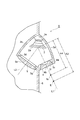
- FIG. 1 It is the perspective view seen from the vehicle interior which shows one Embodiment of the outer mirror for vehicles which concerns on this invention. It is a top view of the vehicle with which the vehicle outer mirror of FIG. 1 was attached. It is sectional drawing of the outer mirror for vehicles of FIG. It is a figure which shows the movement of the visual field direction accompanying the movement of a driver
- an outer mirror 1 for a vehicle includes a mirror housing 3 incorporating a circular plane mirror 2, a circular concave lens 4 disposed on the outer side of the vehicle interior of the mirror housing 3, and a vehicle interior of the mirror housing 3.
- a circular convex lens 5 disposed inside.
- the mirror housing 3 made of a resin material is attached to the front of the left and right window glasses 6 of the vehicle 7 (see FIG. 2), and has an outdoor exposed portion 3a and an indoor exposed portion 3b protruding outside the vehicle compartment.
- the outdoor exposed portion 3a of the mirror housing 3 is formed with a light incident port 3c directed rearward outside the vehicle compartment, and the concave lens 4 is formed in the mirror housing 3 so as to block the light incident port 3c. It is fixed.
- a light exit 3d directed toward the driver in the vehicle compartment is formed in the indoor exposed portion 3b, and the convex lens 5 is fixed to the mirror housing 3 so as to close the light exit 3d.
- the plane mirror 2 is fixed on the optical axis L1 of the concave lens 4 by a mirror holder 3e provided inside the mirror housing 3.
- the plane mirror 2 is disposed so as to reflect the light transmitted through the concave lens 4 toward the convex lens 5.
- the plane mirror 2 is arranged so that the reflected light beam passing through the optical axis L 1 of the concave lens 4 passes through the optical axis L 2 of the convex lens 5.
- the light incident port 3c can be reduced while ensuring a rear visual field range equivalent to that of a general vehicle outer mirror that does not include a lens, and the amount of protrusion of the mirror housing 3 to the outside of the passenger compartment is reduced. be able to.
- FIG. 4 shows the movement in the visual field direction when the driver's viewpoint P1 moves to the viewpoint P2 and the driver's line of sight L3 changes to the line of sight L4.
- the reflecting surface is the concave surface M2
- the movement of the visual field is small (arrow A1) with respect to the movement of the viewpoint and the change of the line of sight, which is unnatural.
- the reflecting surface is the plane M1
- a natural visual field movement that follows the movement of the viewpoint or the change of the line of sight can be obtained (arrow A2). Therefore, the visibility outside the passenger compartment can be improved.
- the light reflected by the plane mirror 2 is transmitted through the convex lens 5 and emitted.
- the image outside the passenger compartment is reduced by the concave lens 4.
- the convex lens 5 enlarges the image outside the passenger compartment, the reduction of the image outside the passenger compartment is suppressed. Therefore, the visibility outside the passenger compartment can be improved.
- the plane mirror 2 is built in the mirror housing 3, foreign matter can be prevented from entering between the concave lens 4 and the plane mirror 2 and between the plane mirror 2 and the convex lens 5. Further, since the concave lens 4 is disposed in the outdoor exposed portion 3a of the mirror housing 3 and the convex lens 5 is disposed in the indoor exposed portion 3b of the mirror housing 3, the driver does not pass through the window glass 6 of the vehicle 7 and is out of the vehicle interior. Can be visually recognized. Therefore, the visibility outside the passenger compartment can be improved.
- the concave lens 4 is a plano-concave lens made of, for example, acrylic, and the flat surface 4b of the concave lens 4 is directed to the outside of the passenger compartment. For this reason, even if the deviation
- the material of the concave lens 4 is not limited to acrylic, and may be other general optical materials, that is, glass, polycarbonate, polyolefin, and the like.
- the outer peripheral surface 4a of the concave lens 4 is a truncated cone surface whose outer diameter increases toward the outside of the passenger compartment. As a result, a wider range of light outside the passenger compartment is transmitted through the concave lens 4, so that the rear visual field range can be further widened.
- the inner peripheral surface 3f of the light incident port 3c is also a truncated cone surface whose outer diameter increases toward the outside of the passenger compartment.
- the concave lens 4 is fitted and adhered to the light incident port 3c from the outside of the passenger compartment so that the outer peripheral surface 4a contacts the inner peripheral surface 3f of the light incident port 3c.
- the outer peripheral surface 4a of the concave lens 4 and the inner peripheral surface 3f of the light incident port 3c abut, the distance between the concave lens 4 and the plane mirror 2 is determined, and the central axis of the light incident port 3c and the concave lens 4 The position with the optical axis L1 is adjusted.
- the convex lens 5 is a plano-convex lens made of acrylic, for example, and the convex surface 5a of the convex lens 5 is directed to the vehicle interior side. For this reason, even if the deviation
- the material of the convex lens 5 is not limited to acrylic, and may be other general optical materials, that is, glass, polycarbonate, polyolefin, and the like.
- FIG. 5A shows the imaging positions when five types of parallel light having different inclinations are incident on the plane Tb of the plano-convex lens T having the convex surface Ta directed toward the vehicle interior side.
- FIG. 5B shows the imaging positions when five types of parallel light having different inclinations are incident on the convex surface Ta of the plano-convex lens T with the plane Tb directed toward the vehicle interior side.
- the imaging position P3 in FIG. 5A and the imaging position P8 in FIG. 5B are imaging positions of parallel light along the optical axis of the plano-convex lens T.
- the imaging position P7 in FIG. 5A and the imaging position P12 in FIG. 5B are imaging positions of parallel light most inclined with respect to the optical axis of the plano-convex lens T.
- the distance between the imaging position P12 and the plano-convex lens T is significantly different from the distance between the imaging position P8 and the plano-convex lens T.
- the distance between the imaging position P7 and the plano-convex lens T is close to the distance between the imaging position P3 and the plano-convex lens T. Accordingly, in FIG. 5A, even if the amount of deviation between the optical axis of the plano-convex lens T and the viewpoint of the driver changes, the enlargement ratio of the image outside the passenger compartment is hardly changed.
- a counterbored hole 3g is formed at the outer edge of the light exit 3d where the convex lens 5 is disposed on the vehicle interior side.
- the inner diameter of the counterbore 3g is substantially the same as the outer diameter of the convex lens 5.
- the convex lens 5 is fitted into the counterbore hole 3g from the vehicle interior side and is bonded in a state of being in contact with the bottom surface of the counterbore hole 3g.
- the distance A3 from the focal point ft of the convex lens 5 outside the passenger compartment to the intersection of the optical axis L2 of the convex lens 5 and the reflecting surface 2a of the plane mirror 2 is from the focal point fo of the concave lens 4 outside the passenger compartment to the optical axis L1 of the concave lens 4. And a distance A4 to the intersection of the plane mirror 2 and the reflecting surface 2a.
- the virtual image outside the vehicle compartment due to the concave lens 4 is positioned closer to the convex lens 5 than the focal point ft of the convex lens 5, so that the enlargement action of the convex lens 5 is reliably utilized and the image outside the vehicle compartment is reliably reduced. Can be suppressed.
- the outer diameter of the reflecting surface 2 a of the plane mirror 2 is greater than or equal to the effective diameter of the concave lens 4. For this reason, since most of the light transmitted through the concave lens 4 can be reflected toward the driver, the rear visual field range can be further widened.
- the light exit port 3d can be enlarged.
- the light exit port 3d functions as a display area for displaying an image outside the vehicle interior toward the vehicle interior. For this reason, if the light emission port 3d is enlarged, an image outside the vehicle compartment can be displayed toward the vehicle interior in a larger display area, so that the image outside the vehicle compartment can be further enlarged. Therefore, the visibility outside the passenger compartment can be improved.
- the outer diameter of the range visually recognized by the driver through the convex lens 5 at the position where the concave lens 4 is disposed is substantially equal to the effective diameter of the concave lens 4.
- the entire area of the convex lens 5 can be effectively used as a means for enlarging the image outside the vehicle compartment, and the visibility outside the vehicle compartment can be improved.
- Such a relationship between the concave lens 4 and the convex lens 5 is obtained, for example, under the following conditions.
- the outer diameter in the range visually recognized by the driver through the convex lens 5 may be smaller than the effective diameter of the concave lens 4 at the position where the concave lens 4 is disposed. That is, the outer peripheral edge of the concave lens 4 that is visible to the driver through the convex lens 5 may be positioned inside the outer peripheral edge of the concave lens 4. In this case, the entire area of the convex lens 5 can be effectively used more reliably as a means for enlarging the image outside the passenger compartment, and the visibility outside the passenger compartment can be improved.
- the outer diameter of the range visible to the driver through the convex lens 5 may be larger than the outer diameter of the concave lens 4 at the position where the concave lens 4 is disposed. That is, the outer peripheral end of the range visually recognized by the driver through the convex lens 5 may be positioned outside the outer peripheral end of the concave lens 4.
- the outer diameter and outer peripheral end of the concave lens 4 are the outer diameter and outer peripheral end of the surface of the concave lens 4 exposed in the mirror housing 3. That is, the outer diameter of the concave lens 4 is the same as the inner diameter of the light incident port 3c. In this case, since the outer peripheral end of the concave lens 4 can be visually recognized through the convex lens 5, the visibility outside the passenger compartment can be further improved.
- Such a relationship between the concave lens 4 and the convex lens 5 is obtained, for example, under the following conditions.
- Effective diameter of convex lens 5 120 mm
- the plano-concave lens 4 may be replaced with a biconcave lens 4A.
- the rear visual field range can be widened without increasing the curvature of the concave surface, that is, without reducing the radius of curvature of the concave surface, compared to using the plano-concave lens 4. For this reason, it is possible to widen the rear visual field range while suppressing distortion of the image outside the passenger compartment, and to improve the visibility outside the passenger compartment.
- plano-convex lens 5 may be replaced with a biconvex lens 5A.
- the enlargement ratio of the image outside the passenger compartment can be increased without increasing the curvature of the convex surface, that is, without decreasing the radius of curvature of the convex surface, compared to using the plano-convex lens 5. For this reason, it is possible to increase the enlargement ratio of the image while suppressing distortion of the image outside the passenger compartment, and to improve the visibility outside the passenger compartment.
- the outer diameter of the reflecting surface 2 a of the plane mirror 2 may be larger than the effective diameter of the concave lens 4 and the effective diameter of the convex lens 5. In this case, since the wide range image outside the passenger compartment can be reflected toward the convex lens 5 by the plane mirror 2, the rear visual field range can be widened, and the visibility outside the passenger compartment can be improved.
- the outer shape of the plane mirror 2, the concave lens 4 and the convex lens 5 is not limited to a circle, and these outer shapes can be changed into various shapes in consideration of installation space and visibility.
- the outer shape of the plane mirror 2, the concave lens 4, and the convex lens 5 may be a polygonal shape such as a triangle, a quadrangle, or a pentagon, and the corners of these shapes may be rounded.
- the inner surface of the mirror housing 3 may be blackened by painting or the like. In this case, the image inside the mirror housing 3 becomes difficult to visually recognize, and the image outside the passenger compartment becomes relatively clear. Therefore, the visibility outside the passenger compartment can be improved.
- the present invention can be used for a vehicle outer mirror.
- SYMBOLS 1 Outer mirror for vehicles, 2 ... Plane mirror, 2a ... Reflecting surface, 3 ... Mirror housing, 3a ... Outdoor exposure part, 3b ... Indoor exposure part, 4, 4A ... Concave lens, 4b ... Plane, 5, 5A ... Convex lens, 5a ...convex.
Landscapes
- Engineering & Computer Science (AREA)
- Multimedia (AREA)
- Mechanical Engineering (AREA)
- Rear-View Mirror Devices That Are Mounted On The Exterior Of The Vehicle (AREA)
Description
本発明は、レンズと反射鏡とを備え、車室外の後方の視認を可能にする車両用アウターミラーに関する。
従来、このような車両用アウターミラーには、車室外の後方からの光が透過する凹レンズと、凹レンズを透過した入射光を反射させる凹面鏡とを備えたものが開示されている(例えば、特許文献1参照)。
特許文献1に記載された車両用アウターミラーでは、車室外の光は凹レンズを透過して入射する。このため、レンズを備えていない一般的な車両用アウターミラーと同等の後方視野範囲を確保しつつ、車室外の光の入射部を小さくすることができ、レンズを備えていない車両用アウターミラーと比べ車室外への突出量を小さくすることができる。また、凹レンズを透過した光は凹面鏡によって反射される。このため、凹面鏡の拡大作用によって車室外の像の縮小を抑制することができる。
しかしながら、特許文献1に記載された車両用アウターミラーでは、車室外から入射した光を車室内の運転者に向かって反射させるために、凹面鏡の光軸は運転者の視点からずれた方向に向けられる。これにより、運転者の視点と凹面鏡の反射面上の各点との距離が不均一となるため、車室外の像の拡大率が不均一となり、車室外の像の歪みが大きくなる。また、凹面鏡に対して視点を動かしたときの視野の動きは、平面鏡に対して視点を動かしたときの視野の動きに比べて不自然な動きとなる。従って、車室外の視認性が悪化するおそれがある。
本発明は、車室外の視認性を良好にしつつ、車室外への突出量を小さくすることができる車両用アウターミラーを提供することを目的とする。
本発明に係る車両用アウターミラーは、車室外の後方の視認を可能にする車両用アウターミラーであって、車室外の後方からの光が透過する凹レンズと、凹レンズを透過した光が車室内側に向かって透過する凸レンズと、凹レンズの光軸上に配置され、凹レンズを透過した光を凸レンズに向かって反射させる平面鏡と、を備えたことを特徴とする。
このような車両用アウターミラーでは、車室外の光は凹レンズを透過して入射する。このため、レンズを備えていない一般的な車両用アウターミラーと同等の後方視野範囲を確保しつつ、車室外の光の入射部を小さくすることができ、車室外への突出量を小さくすることができる。また、凹レンズを透過した光は、凹レンズの光軸上に配置された平面鏡により凸レンズに向かって反射され、凸レンズを透過して出射する。このため、凸レンズの拡大作用によって車室外の像の縮小を抑制することができる。更に、平面鏡には拡大・縮小作用がないため、平面鏡の向きによって車室外の像の歪みが大きくなることはない。また、平面鏡では、視点を動かしたときの視野の動きが自然な動きとなる。従って、車室外の視認性を良好にしつつ、車室外への突出量を小さくすることができる。
平面鏡はハウジング内に配置され、凹レンズはハウジングの車室外側に配置され、凸レンズはハウジングの車室内側に配置されていてもよい。この場合、凹レンズと平面鏡との間及び凸レンズと平面鏡との間への異物の侵入が防止される。また、凹レンズが車室外に配置され、凸レンズが車室内に配置されているため、運転者は、車両のウィンドウガラスを通さずに車室外を視認することができる。従って、車室外の視認性をより良好にすることができる。
凸レンズの車室外側の焦点から、凸レンズの光軸と平面鏡の反射面との交点までの距離は、凹レンズの車室外側の焦点から、凹レンズの光軸と平面鏡の反射面との交点までの距離よりも大きくてもよい。この場合、凸レンズによる拡大作用を確実に活用し、車室外の像の縮小を確実に抑制することができる。
凸レンズは平凸レンズであり、凸レンズの凸面は車室内側に向けられていてもよい。この場合、凸レンズの光軸と視点とのずれ量が変わっても車室外の像の拡大率が変わり難くなるので、車室外の視認性をより良好にすることができる。
凹レンズは平凹レンズであり、凹レンズの平面は車室外側に向けられていてもよい。この場合、凹レンズの光軸と車室外の物体とのずれ量が変わってもその物体の像の拡大率が変わり難くなるので、車室外の視認性をより良好にすることができる。
凹レンズは両凹レンズであってもよい。この場合、凹レンズが平凹レンズであるのに比べ、凹面の曲率を大きくすることなく、すなわち凹面の曲率半径を小さくすることなく後方視野範囲を広くすることができる。このため、車室外の像の歪みを抑制しながら後方視野範囲を広くすることができ、車室外の視認性をより良好にすることができる。
凹レンズ、凸レンズ及び平面鏡のそれぞれの外形は円形であり、平面鏡の反射面の外径は凹レンズの有効径以上であり、凸レンズの有効径は平面鏡の反射面の外径よりも大きくてもよい。この場合、平面鏡の反射面の外径が凹レンズの有効径以上であることにより、凹レンズを透過した光の多くを運転者に向かって反射させることができるので、後方視野範囲をより広くすることができる。また、凸レンズの有効径が平面鏡の反射面の外径よりも大きいことにより、車室外の像をより大きい表示領域で車室内に向かって表示することができるので、車室外の像をより拡大することができる。従って、車室外の視認性をより良好にすることができる。
凹レンズ、凸レンズ及び平面鏡のそれぞれの外形は円形であり、平面鏡の反射面の外径は凹レンズの有効径及び凸レンズの有効径よりも大きくてもよい。この場合、平面鏡によって、車室外の広範囲の像を凸レンズに向かって反射させることができるため、後方視野範囲を広くすることができ、車室外の視認性をより良好にすることができる。
凹レンズのうち、凸レンズを通して運転者に視認される部分の外周端は、凹レンズの外周端よりも内側に位置していてもよい。この場合、車室外の像の拡大手段として凸レンズの全域を有効活用し、車室外の視認性をより良好にすることができる。
凸レンズを通して運転者に視認される範囲の外周端は、凹レンズの外周端よりも外側に位置していてもよい。この場合、凸レンズを通して凹レンズの外周端を視認することができるので、車室外の視認性をより良好にすることができる。
このように、本発明に係る車両用アウターミラーによれば、車室外の視認性を良好にしつつ、車室外への突出量を小さくすることができる。
図1に示されるように、車両用アウターミラー1は、円形の平面鏡2を内蔵したミラーハウジング3と、ミラーハウジング3の車室外側に配置された円形の凹レンズ4と、ミラーハウジング3の車室内側に配置された円形の凸レンズ5と、を備えている。
例えば樹脂材料からなるミラーハウジング3は、車両7の左右のウィンドウガラス6の前方に取り付けられ(図2参照)、車室外に突出する室外露出部3aと室内露出部3bとを有している。
図3に示されるように、ミラーハウジング3の室外露出部3aには、車室外の後方に向けられた光入射口3cが形成され、凹レンズ4は光入射口3cを塞ぐようにミラーハウジング3に固定されている。室内露出部3bには、車室内の運転者に向けられた光出射口3dが形成され、凸レンズ5は光出射口3dを塞ぐようにミラーハウジング3に固定されている。
平面鏡2は、ミラーハウジング3の内部に設けられたミラーホルダ3eによって凹レンズ4の光軸L1上に固定されている。平面鏡2は、凹レンズ4を透過した光を凸レンズ5に向かって反射するように配置されている。特に本実施形態では、平面鏡2は、凹レンズ4の光軸L1を通る光線の反射光線が、凸レンズ5の光軸L2を通るように配置されている。
凹レンズ4には車室外の光が入射する。このため、レンズを備えていない一般的な車両用アウターミラーと同等の後方視野範囲を確保しつつ、光入射口3cを小さくすることができ、ミラーハウジング3の車室外への突出量を小さくすることができる。
凹レンズ4を透過した光は平面鏡2によって凸レンズ5に向かって反射される。平面鏡2には拡大・縮小作用がないため、平面鏡2の向きによって車室外の像の歪みが大きくなることはない。また、平面鏡2では、視点を動かしたときの視野の動きが自然な動きとなる。図4は、運転者の視点P1が視点P2に移動すると共に、運転者の視線L3が視線L4に変わった場合の視野方向の動きを示している。例えば、反射面が凹面M2である場合には、視点の動きや視線の変化に対して視野の動きが小さく(矢印A1)、不自然である。これに対し、反射面が平面M1であれば、視点の動きや視線の変化に追従した自然な視野の動きが得られる(矢印A2)。従って、車室外の視認性を良好にすることができる。
平面鏡2で反射した光は凸レンズ5を透過して出射される。上述したように、車室外の光は凹レンズ4を透過するため、車室外の像は凹レンズ4によって縮小される。これに対し凸レンズ5は車室外の像を拡大させるため、車室外の像の縮小が抑制される。従って、車室外の視認性をより良好にすることができる。
更に、平面鏡2はミラーハウジング3に内蔵されているため、凹レンズ4と平面鏡2との間及び平面鏡2と凸レンズ5との間への異物の侵入が防止される。また、凹レンズ4はミラーハウジング3の室外露出部3aに配置され、凸レンズ5はミラーハウジング3の室内露出部3bに配置されているため、運転者は車両7のウィンドウガラス6を通さずに車室外を視認することができる。従って、車室外の視認性をより良好にすることができる。
凹レンズ4及び凸レンズ5についてより詳細に説明する。図3に示されるように、凹レンズ4は例えばアクリルからなる平凹レンズであり、凹レンズ4の平面4bは車室外側に向けられている。このため、凹レンズ4の光軸L1と車室外の物体とのずれ量が変わっても、その物体の像の拡大率が変わり難くなるので、車室外の視認性をより良好にすることができる。なお、凹レンズ4の材料は、アクリルに限定されるものではなく、他の一般的な光学材料、すなわちガラス、ポリカーボネート、ポリオレフィン等であってもよい。
凹レンズ4の外周面4aは車室外側に向うにつれて外径が大きくなる円錐台の面になっている。これにより、車室外のより広範囲の光が凹レンズ4を透過するため、後方視野範囲をより広くすることができる。
凹レンズ4の外周面4aに対応して、光入射口3cの内周面3fも車室外側に向うに従い外径が大きくなる円錐台の面になっている。そして、凹レンズ4は、外周面4aが光入射口3cの内周面3fと当接するように、車室外側から光入射口3cにはめ込まれ、接着されている。このように、凹レンズ4の外周面4aと光入射口3cの内周面3fとが当接することによって、凹レンズ4と平面鏡2との距離が定まると共に、光入射口3cの中心軸と凹レンズ4の光軸L1との位置が合わせられる。
凸レンズ5は例えばアクリルからなる平凸レンズであり、凸レンズ5の凸面5aは車室内側に向けられている。このため、凸レンズ5の光軸L2と運転者の視点とのずれ量が変わっても、車室外の像の拡大率が変わり難くなるので、車室外の視認性をより良好にすることができる。なお、凸レンズ5の材料はアクリルに限定されるものではなく、他の一般的な光学材料、すなわちガラス、ポリカーボネート、ポリオレフィン等であってもよい。
図5(a)は、凸面Taが車室内側に向けられた平凸レンズTの平面Tbに、傾きが異なる5種類の平行光が入射した場合の結像位置を示している。図5(b)は、平面Tbが車室内側に向けられた平凸レンズTの凸面Taに、傾きが異なる5種類の平行光が入射した場合の結像位置を示している。図5(a)の結像位置P3及び図5(b)の結像位置P8は、平凸レンズTの光軸に沿う平行光の結像位置である。図5(a)の結像位置P7及び図5(b)の結像位置P12は、平凸レンズTの光軸に対して最も傾いた平行光の結像位置である。図5(b)では、結像位置P12と平凸レンズTとの距離は、結像位置P8と平凸レンズTとの距離に比べ大幅に異なっている。これに対し、図5(a)では、結像位置P7と平凸レンズTとの距離は、結像位置P3と平凸レンズTとの距離に近くなっている。これにより、図5(a)では、平凸レンズTの光軸と運転者の視点とのずれ量が変わっても、車室外の像の拡大率が変わり難くなっている。
図3に示されるように、凸レンズ5が配置される光出射口3dの車室内側の外縁にはザグリ穴3gが形成されている。ザグリ穴3gの内径は、凸レンズ5の外径と略同等である。凸レンズ5は、ザグリ穴3gに車室内側からはめ込まれ、ザグリ穴3gの底面に当接した状態で接着されている。
凸レンズ5の車室外側の焦点ftから、凸レンズ5の光軸L2と平面鏡2の反射面2aとの交点までの距離A3は、凹レンズ4の車室外側の焦点foから、凹レンズ4の光軸L1と平面鏡2の反射面2aとの交点までの距離A4よりも大きくなっている。これにより、凹レンズ4による車室外の虚像が、凸レンズ5の焦点ftよりも凸レンズ5の近くに位置することとなるため、凸レンズ5の拡大作用を確実に活用し、車室外の像の縮小を確実に抑制することができる。
続いて、平面鏡2、凹レンズ4及び凸レンズ5の外形の大きさの関係について説明する。平面鏡2の反射面2aの外径は、凹レンズ4の有効径以上となっている。このため、凹レンズ4を透過した光の多くを運転者に向かって反射させることができるので、後方視野範囲をより広くすることができる。
また、凸レンズ5の有効径は、平面鏡2の反射面2aの外径よりも大きいため、光出射口3dを大きくすることができる。光出射口3dは、車室内に向けて車室外の像を表示する表示領域として機能する。このため、光出射口3dを大きくすると、車室外の像をより大きい表示領域で車室内に向かって表示することができるので、車室外の像をより拡大することができる。従って、車室外の視認性をより良好にすることができる。
更に、凹レンズ4が配置されている位置において、凸レンズ5を通して運転者に視認される範囲の外径は、凹レンズ4の有効径と略同等になっている。これにより、凸レンズ5の全域を車室外の像の拡大手段として有効活用し、車室外の視認性をより良好にすることができる。凹レンズ4と凸レンズ5とのこのような関係は、例えば、次のような条件で得られる。
凸レンズ5の主点と運転者の視点との距離:400mm~700mm
凸レンズ5の光軸L2と平面鏡2との交点と、凸レンズ5の主点との距離:90mm
凸レンズ5の車室外側の焦点距離:520mm
凸レンズ5の有効径:80mm
凹レンズ4の光軸L1と平面鏡2との交点と、凹レンズ4の主点との距離:120mm
凹レンズ4の車室外側の焦点距離:235mm
凹レンズ4の有効径:70mm
平面鏡2の反射面2aの外径:70mm
凸レンズ5の主点と運転者の視点との距離:400mm~700mm
凸レンズ5の光軸L2と平面鏡2との交点と、凸レンズ5の主点との距離:90mm
凸レンズ5の車室外側の焦点距離:520mm
凸レンズ5の有効径:80mm
凹レンズ4の光軸L1と平面鏡2との交点と、凹レンズ4の主点との距離:120mm
凹レンズ4の車室外側の焦点距離:235mm
凹レンズ4の有効径:70mm
平面鏡2の反射面2aの外径:70mm
なお、凹レンズ4が配置されている位置において、凸レンズ5を通して運転者に視認される範囲の外径を、凹レンズ4の有効径よりも小さくしてもよい。すなわち、凹レンズ4のうち、凸レンズ5を通して運転者に視認される部分の外周端が、凹レンズ4の外周端よりも内側に位置するようにしてもよい。この場合、凸レンズ5の全域を車室外の像の拡大手段としてより確実に有効活用し、車室外の視認性をより良好にすることができる。
また、凹レンズ4が配置されている位置において、凸レンズ5を通して運転者に視認される範囲の外径を、凹レンズ4の外径よりも大きくしてもよい。すなわち、凸レンズ5を通して運転者に視認される範囲の外周端が、凹レンズ4の外周端よりも外側に位置するようにしてもよい。凹レンズ4の外径及び外周端とは、凹レンズ4のミラーハウジング3内に露出する面の外径及び外周端である。つまり、凹レンズ4の外径は、光入射口3cの内径と同じである。この場合、凸レンズ5を通して凹レンズ4の外周端を視認することができるので、車室外の視認性をより良好にすることができる。凹レンズ4と凸レンズ5とのこのような関係は、例えば、次のような条件で得られる。
凸レンズ5の主点と運転者の視点との距離:1733mm
凸レンズ5の光軸L2と平面鏡2との交点と、凸レンズ5の主点との距離:188mm
凸レンズ5の車室外側の焦点距離:520mm
凸レンズ5の有効径:120mm
凹レンズ4の光軸L1と平面鏡2との交点と、凹レンズ4の主点との距離:231mm
凹レンズ4の車室外側の焦点距離:78mm
凹レンズ4の有効径:50mm
凹レンズ4の外径:54mm
平面鏡2の反射面2aの外径:95mm
凸レンズ5の主点と運転者の視点との距離:1733mm
凸レンズ5の光軸L2と平面鏡2との交点と、凸レンズ5の主点との距離:188mm
凸レンズ5の車室外側の焦点距離:520mm
凸レンズ5の有効径:120mm
凹レンズ4の光軸L1と平面鏡2との交点と、凹レンズ4の主点との距離:231mm
凹レンズ4の車室外側の焦点距離:78mm
凹レンズ4の有効径:50mm
凹レンズ4の外径:54mm
平面鏡2の反射面2aの外径:95mm
以上、本発明の好適な実施形態について説明してきたが、本発明は上述した実施形態に限定されるものではなく、その要旨を逸脱しない範囲で様々な変形が可能である。例えば、図6に示されるように、平凹レンズ4を両凹レンズ4Aに替えてもよい。この場合、平凹レンズ4を用いるのに比べ、凹面の曲率を大きくすることなく、すなわち凹面の曲率半径を小さくすることなく後方視野範囲を広くすることができる。このため、車室外の像の歪みを抑制しながら後方視野範囲を広くすることができ、車室外の視認性をより良好にすることができる。
また、平凸レンズ5を両凸レンズ5Aに替えてもよい。この場合、平凸レンズ5を用いるのに比べ、凸面の曲率を大きくすることなく、すなわち凸面の曲率半径を小さくすることなく車室外の像の拡大率を高くすることができる。このため、車室外の像の歪みを抑制しながら像の拡大率を高くすることができ、車室外の視認性をより良好にすることができる。
また、平面鏡2の反射面2aの外径を凹レンズ4の有効径及び凸レンズ5の有効径よりも大きくしてもよい。この場合、平面鏡2によって、車室外の広範囲の像を凸レンズ5に向かって反射させることができるため、後方視野範囲を広くすることができ、車室外の視認性をより良好にすることができる。
また、平面鏡2、凹レンズ4及び凸レンズ5の外形は円形に限られず、設置スペースや視認性を考慮して、これらの外形を様々な形状に変えることができる。例えば、平面鏡2、凹レンズ4及び凸レンズ5の外形を、三角形、四角形、又は五角形等の多角形状としてもよいし、これらの形状の角部を丸めてもよい。
また、ミラーハウジング3の内面を塗装等によって黒色にしてもよい。この場合、ミラーハウジング3内の像が視認し難くなり、相対的に車室外の像が明瞭となる。従って、車室外の視認性をより良好にすることができる。
本発明は、車両用アウターミラーに利用できる。
1…車両用アウターミラー、2…平面鏡、2a…反射面、3…ミラーハウジング、3a…室外露出部、3b…室内露出部、4,4A…凹レンズ、4b…平面、5,5A…凸レンズ、5a…凸面。
Claims (10)
- 車室外の後方の視認を可能にする車両用アウターミラーであって、
前記車室外の後方からの光が透過する凹レンズと、
前記凹レンズを透過した前記光が車室内側に向かって透過する凸レンズと、
前記凹レンズの光軸上に配置され、前記凹レンズを透過した前記光を前記凸レンズに向かって反射させる平面鏡と、を備えたことを特徴とする車両用アウターミラー。 - 前記平面鏡はハウジング内に配置され、
前記凹レンズは前記ハウジングの前記車室外側に配置され、
前記凸レンズは前記ハウジングの前記車室内側に配置されていることを特徴とする請求項1記載の車両用アウターミラー。 - 前記凸レンズの前記車室外側の焦点から、前記凸レンズの光軸と前記平面鏡の反射面との交点までの距離は、前記凹レンズの前記車室外側の焦点から、前記凹レンズの前記光軸と前記平面鏡の反射面との交点までの距離よりも大きいことを特徴とする請求項1又は2記載の車両用アウターミラー。
- 前記凸レンズは平凸レンズであり、
前記凸レンズの凸面は前記車室内側に向けられていることを特徴とする請求項1~3のいずれか一項記載の車両用アウターミラー。 - 前記凹レンズは平凹レンズであり、
前記凹レンズの平面は前記車室外側に向けられていることを特徴とする請求項1~4のいずれか一項記載の車両用アウターミラー。 - 前記凹レンズは両凹レンズであることを特徴とする請求項1~4のいずれか一項記載の車両用アウターミラー。
- 前記凹レンズ、前記凸レンズ及び前記平面鏡のそれぞれの外形は円形であり、
前記平面鏡の反射面の外径は前記凹レンズの有効径以上であり、
前記凸レンズの有効径は前記平面鏡の反射面の外径よりも大きいことを特徴とする請求項1~6のいずれか一項記載の車両用アウターミラー。 - 前記凹レンズ、前記凸レンズ及び前記平面鏡のそれぞれの外形は円形であり、
前記平面鏡の反射面の外径は前記凹レンズの有効径及び前記凸レンズの有効径よりも大きいことを特徴とする請求項1~6のいずれか一項記載の車両用アウターミラー。 - 前記凹レンズのうち、前記凸レンズを通して運転者に視認される部分の外周端は、前記凹レンズの外周端よりも内側に位置していることを特徴とする請求項1~8のいずれか一項記載の車両用アウターミラー。
- 前記凸レンズを通して運転者に視認される範囲の外周端は、前記凹レンズの外周端よりも外側に位置していることを特徴とする請求項1~8のいずれか一項記載の車両用アウターミラー。
Applications Claiming Priority (2)
| Application Number | Priority Date | Filing Date | Title |
|---|---|---|---|
| JP2012-010357 | 2012-01-20 | ||
| JP2012010357A JP2013052859A (ja) | 2011-08-09 | 2012-01-20 | 車両用アウターミラー |
Publications (1)
| Publication Number | Publication Date |
|---|---|
| WO2013108683A1 true WO2013108683A1 (ja) | 2013-07-25 |
Family
ID=48799827
Family Applications (1)
| Application Number | Title | Priority Date | Filing Date |
|---|---|---|---|
| PCT/JP2013/050201 Ceased WO2013108683A1 (ja) | 2012-01-20 | 2013-01-09 | 車両用アウターミラー |
Country Status (1)
| Country | Link |
|---|---|
| WO (1) | WO2013108683A1 (ja) |
Citations (5)
| Publication number | Priority date | Publication date | Assignee | Title |
|---|---|---|---|---|
| FR1079274A (fr) * | 1953-04-30 | 1954-11-29 | Dispositif rétroviseur, notamment pour automobiles et applications analogues | |
| JPS6285008A (ja) * | 1985-08-21 | 1987-04-18 | デイビツド ハ−バ−ト ブロウア− | 保護ヘルメツト |
| JPH0713594U (ja) * | 1993-08-04 | 1995-03-07 | 株式会社村上開明堂 | 車外視認装置 |
| EP0901937A1 (fr) * | 1997-09-10 | 1999-03-17 | Automobiles Peugeot | Rétroviseur pour véhicules automobiles |
| FR2820097A1 (fr) * | 2001-01-30 | 2002-08-02 | Peugeot Citroen Automobiles Sa | Retrovisseur a encombrement reduit a faible surface frontale |
-
2013
- 2013-01-09 WO PCT/JP2013/050201 patent/WO2013108683A1/ja not_active Ceased
Patent Citations (5)
| Publication number | Priority date | Publication date | Assignee | Title |
|---|---|---|---|---|
| FR1079274A (fr) * | 1953-04-30 | 1954-11-29 | Dispositif rétroviseur, notamment pour automobiles et applications analogues | |
| JPS6285008A (ja) * | 1985-08-21 | 1987-04-18 | デイビツド ハ−バ−ト ブロウア− | 保護ヘルメツト |
| JPH0713594U (ja) * | 1993-08-04 | 1995-03-07 | 株式会社村上開明堂 | 車外視認装置 |
| EP0901937A1 (fr) * | 1997-09-10 | 1999-03-17 | Automobiles Peugeot | Rétroviseur pour véhicules automobiles |
| FR2820097A1 (fr) * | 2001-01-30 | 2002-08-02 | Peugeot Citroen Automobiles Sa | Retrovisseur a encombrement reduit a faible surface frontale |
Similar Documents
| Publication | Publication Date | Title |
|---|---|---|
| JP6582245B2 (ja) | ヘッドアップディスプレイ及び車両 | |
| JP6650584B2 (ja) | ヘッドアップディスプレイおよびヘッドアップディスプレイを搭載した移動体 | |
| US7652825B2 (en) | Cover for head-up display | |
| JP6427095B2 (ja) | 表示光投影用光学システム | |
| JP6630921B2 (ja) | ヘッドアップディスプレイおよびヘッドアップディスプレイを搭載した移動体 | |
| JP6561323B2 (ja) | ヘッドアップディスプレイ | |
| WO2017061040A1 (ja) | 投影光学系及びヘッドアップディスプレイ装置 | |
| KR100867439B1 (ko) | 차량용 후면경 | |
| JPWO2016038767A1 (ja) | ヘッドアップディスプレイ及び移動体 | |
| JP6283826B2 (ja) | ヘッドアップディスプレイおよびヘッドアップディスプレイを搭載した移動体 | |
| JPWO2018066062A1 (ja) | 投影光学系、及びヘッドアップディスプレイ装置 | |
| JP2013052859A (ja) | 車両用アウターミラー | |
| JP7115471B2 (ja) | ヘッドアップディスプレイ装置 | |
| JP6652375B2 (ja) | 表示用反射板、表示光投影用光学システム、およびウインドシールドの製造方法 | |
| JP2016002975A (ja) | 死角補助装置 | |
| JPWO2018186149A1 (ja) | ヘッドアップディスプレイシステム、およびヘッドアップディスプレイシステムを備える移動体 | |
| KR102413740B1 (ko) | 차량용 헤드 업 디스플레이 장치 | |
| JP4231484B2 (ja) | アウトサイドミラー装置 | |
| TWI651223B (zh) | 車輛用側視鏡 | |
| JP2013147190A (ja) | 車両用アウターミラー | |
| KR101517172B1 (ko) | 차량용 사이드 미러 | |
| JP2001013451A (ja) | 拡大表示装置 | |
| JP2016049930A (ja) | 死角補助装置 | |
| WO2013108682A1 (ja) | 車外視認装置 | |
| JP2006176067A (ja) | ドアミラー |
Legal Events
| Date | Code | Title | Description |
|---|---|---|---|
| 121 | Ep: the epo has been informed by wipo that ep was designated in this application |
Ref document number: 13738234 Country of ref document: EP Kind code of ref document: A1 |
|
| NENP | Non-entry into the national phase |
Ref country code: DE |
|
| 122 | Ep: pct application non-entry in european phase |
Ref document number: 13738234 Country of ref document: EP Kind code of ref document: A1 |