WO2013108580A1 - Appareil endoscopique, dispositif d'actionnement pour appareil endoscopique et procédé de commande pour appareil endoscopique - Google Patents
Appareil endoscopique, dispositif d'actionnement pour appareil endoscopique et procédé de commande pour appareil endoscopique Download PDFInfo
- Publication number
- WO2013108580A1 WO2013108580A1 PCT/JP2012/084173 JP2012084173W WO2013108580A1 WO 2013108580 A1 WO2013108580 A1 WO 2013108580A1 JP 2012084173 W JP2012084173 W JP 2012084173W WO 2013108580 A1 WO2013108580 A1 WO 2013108580A1
- Authority
- WO
- WIPO (PCT)
- Prior art keywords
- focus
- unit
- control
- control unit
- object position
- Prior art date
Links
Images


Classifications
-
- A—HUMAN NECESSITIES
- A61—MEDICAL OR VETERINARY SCIENCE; HYGIENE
- A61B—DIAGNOSIS; SURGERY; IDENTIFICATION
- A61B1/00—Instruments for performing medical examinations of the interior of cavities or tubes of the body by visual or photographical inspection, e.g. endoscopes; Illuminating arrangements therefor
- A61B1/00002—Operational features of endoscopes
- A61B1/00004—Operational features of endoscopes characterised by electronic signal processing
- A61B1/00006—Operational features of endoscopes characterised by electronic signal processing of control signals
-
- A—HUMAN NECESSITIES
- A61—MEDICAL OR VETERINARY SCIENCE; HYGIENE
- A61B—DIAGNOSIS; SURGERY; IDENTIFICATION
- A61B1/00—Instruments for performing medical examinations of the interior of cavities or tubes of the body by visual or photographical inspection, e.g. endoscopes; Illuminating arrangements therefor
- A61B1/00163—Optical arrangements
- A61B1/00188—Optical arrangements with focusing or zooming features
-
- G—PHYSICS
- G02—OPTICS
- G02B—OPTICAL ELEMENTS, SYSTEMS OR APPARATUS
- G02B23/00—Telescopes, e.g. binoculars; Periscopes; Instruments for viewing the inside of hollow bodies; Viewfinders; Optical aiming or sighting devices
- G02B23/24—Instruments or systems for viewing the inside of hollow bodies, e.g. fibrescopes
- G02B23/2476—Non-optical details, e.g. housings, mountings, supports
- G02B23/2484—Arrangements in relation to a camera or imaging device
-
- G—PHYSICS
- G03—PHOTOGRAPHY; CINEMATOGRAPHY; ANALOGOUS TECHNIQUES USING WAVES OTHER THAN OPTICAL WAVES; ELECTROGRAPHY; HOLOGRAPHY
- G03B—APPARATUS OR ARRANGEMENTS FOR TAKING PHOTOGRAPHS OR FOR PROJECTING OR VIEWING THEM; APPARATUS OR ARRANGEMENTS EMPLOYING ANALOGOUS TECHNIQUES USING WAVES OTHER THAN OPTICAL WAVES; ACCESSORIES THEREFOR
- G03B13/00—Viewfinders; Focusing aids for cameras; Means for focusing for cameras; Autofocus systems for cameras
- G03B13/32—Means for focusing
- G03B13/34—Power focusing
- G03B13/36—Autofocus systems
-
- H—ELECTRICITY
- H04—ELECTRIC COMMUNICATION TECHNIQUE
- H04N—PICTORIAL COMMUNICATION, e.g. TELEVISION
- H04N23/00—Cameras or camera modules comprising electronic image sensors; Control thereof
- H04N23/50—Constructional details
- H04N23/555—Constructional details for picking-up images in sites, inaccessible due to their dimensions or hazardous conditions, e.g. endoscopes or borescopes
-
- H—ELECTRICITY
- H04—ELECTRIC COMMUNICATION TECHNIQUE
- H04N—PICTORIAL COMMUNICATION, e.g. TELEVISION
- H04N23/00—Cameras or camera modules comprising electronic image sensors; Control thereof
- H04N23/60—Control of cameras or camera modules
- H04N23/67—Focus control based on electronic image sensor signals
- H04N23/672—Focus control based on electronic image sensor signals based on the phase difference signals
-
- H—ELECTRICITY
- H04—ELECTRIC COMMUNICATION TECHNIQUE
- H04N—PICTORIAL COMMUNICATION, e.g. TELEVISION
- H04N23/00—Cameras or camera modules comprising electronic image sensors; Control thereof
- H04N23/60—Control of cameras or camera modules
- H04N23/67—Focus control based on electronic image sensor signals
- H04N23/673—Focus control based on electronic image sensor signals based on contrast or high frequency components of image signals, e.g. hill climbing method
-
- A—HUMAN NECESSITIES
- A61—MEDICAL OR VETERINARY SCIENCE; HYGIENE
- A61B—DIAGNOSIS; SURGERY; IDENTIFICATION
- A61B1/00—Instruments for performing medical examinations of the interior of cavities or tubes of the body by visual or photographical inspection, e.g. endoscopes; Illuminating arrangements therefor
- A61B1/00002—Operational features of endoscopes
- A61B1/00039—Operational features of endoscopes provided with input arrangements for the user
- A61B1/00042—Operational features of endoscopes provided with input arrangements for the user for mechanical operation
Definitions
- the present invention relates to an endoscope apparatus, an operation apparatus for an endoscope apparatus, a control method of an endoscope apparatus, and the like.
- Patent Document 1 discloses an endoscope apparatus that performs automatic focusing control using area division and a contrast method. As a result, the complexity of manually performing focus control is reduced, and operability can be improved.
- the imaging device which provides the pixel for phase difference detection in an image pick-up element, and performs an automatic focus control is disclosed.
- the configuration in which the pixels for phase difference detection are provided in the imaging device is compact, and it is considered that mounting on the tip of the endoscope is also possible. As a result, the speed of automatic focus control can be increased, and the operability can be improved.
- Patent Document 3 discloses an endoscope apparatus that switches between automatic focus control and manual focus control based on a luminance level, a magnification factor, and the like. As a result, it is possible to cope with a scene where automatic focus control is not good, and operability can be improved.
- JP 2011-139760 A JP, 2011-59337, A JP, 2009-142586, A
- Patent Document 1 and Patent Document 2 work well when the region of interest such as a lesion converges to one point, but when multiple regions of interest exist at the near point and the far point, or one region of interest is near There is a problem that can not be dealt with when there is a wide range from point to far point.
- Patent Document 3 switching between automatic focus control and manual focus control is limited. Therefore, even when the automatic focus control operates properly, there is a possibility that the manual focus control may be performed, and the switching of the focus control method by the system is only an auxiliary one. Therefore, there is a problem that it is necessary for the user to pay sufficient attention to the state of focus control in order to perform effective focus control.
- an endoscope apparatus an operation apparatus for an endoscope apparatus, a control method of an endoscope apparatus, and the like that simplify switching between automatic focus control and manual focus control. it can.
- switching by the system of automatic focus control and manual focus control, switching based on user operation of automatic focus control and manual focus control, and movement of the in-focus object position are efficiently performed.
- One aspect of the present invention is a focus control unit that controls an optical system to control an in-focus object position, an automatic focusing that automatically controls the in-focus object position, and a control by the focus control unit.
- a switching control unit for switching between manual focusing for manually controlling the in-focus object position, and an operation unit for receiving an operation from a user, in a period in which the automatic focusing is performed in the focus control unit;
- the switching control unit switches control in the focus control unit from the automatic focusing to the manual focusing, and the focus control unit is configured to receive the in-focus object.
- the present invention relates to an endoscope apparatus that performs control to move a position to a position different from that at the time of receiving the operation.
- the endoscope apparatus having a configuration for switching between automatic focus and manual focus
- switching to manual focus is performed.
- Movement of the in-focus object position is performed. Therefore, since the two processes can be performed by the common operation, the configuration of the operation unit can be simplified, and the burden on the user in focus control can be reduced.
- Another aspect of the present invention is a focus control unit that performs control of an optical system to control the in-focus object position, automatic focusing that automatically controls the in-focus object position, and control of the focus control unit.
- a scene that detects a scene change based on a switching control unit that switches between manual focusing in which the in-focus object position is manually controlled, an operation unit that receives an operation from a user, and a captured image captured by an imaging unit
- a change detection unit wherein the switching control unit controls the focus control when the operation unit receives the operation from the user when the automatic focusing is performed by the focus control unit. Switching the control in the unit to the manual focus, the manual control being performed by the focus control unit, the scene When the scene change is detected by the reduction detection unit, related to control in the focus control unit to an endoscope apparatus that switches to the automatic focusing.
- Another aspect of the present invention is an operation receiving unit that receives from a user an operation of an endoscope apparatus having an optical system capable of controlling an in-focus object position, and an output unit that outputs an operation signal according to the operation. And the output unit is configured to automatically switch the in-focus object position according to the user's operation on the operation reception unit, to switch to a manual focus in which the in-focus object position is manually controlled.
- the present invention relates to an operating device for an endoscope apparatus which outputs the operation signal to instruct and outputs the operation signal instructing movement of the in-focus object position to a position different from that at the time of the operation reception.
- Another aspect of the present invention is a control method of an endoscope apparatus which controls an optical system to control an in-focus object position, which receives an operation from a user and is based on the received operation from the user.
- Switching control for switching between the automatic focusing for automatically controlling the in-focus object position and the manual focusing for manually controlling the in-focus object position, and the in-focus object position being different from that at the time of reception of the operation
- the operation unit receives the operation from the user during the period in which the automatic focusing is performed in the focus control unit, the automatic focusing is performed from the automatic focusing as the switching control.
- the present invention relates to a control method of an endoscope apparatus that performs control to switch to manual focus.
- Another aspect of the present invention is a control method of an endoscope apparatus that controls an optical system to control the position of an in-focus object, and a reception process for receiving an operation from a user, and an image taken by an imaging unit
- An automatic focusing process for automatically controlling the in-focus object position based on at least one of a result of the reception process and a result of the scene change detection process, and a scene change detection process based on an image;
- the switching control is performed as the switching control when the operation from the user is received as a result of the receiving process.
- the control to switch from the automatic focusing to the manual focusing is performed, and the manual focusing is performed.
- Te when a scene change as a result of the scene change detection process is detected, as the switching control, related to the control method of an endoscope apparatus which performs control for switching from the manual focus control to the automatic focus.
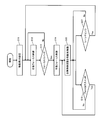
- FIG. 1 is a configuration example of the endoscope apparatus of the present embodiment.
- FIG. 2A shows an example of the configuration of the tip end
- FIG. FIGS. 3A and 3B are diagrams for explaining the relationship between the in-focus object position and the depth of field range in discrete focus control.
- FIG. 4 is a flowchart for explaining the processing of the present embodiment.
- FIG. 5 shows an example of the configuration of the automatic focusing unit.
- FIG. 6 shows an example of the configuration of the manual focusing unit.
- FIG. 7 shows another configuration example of the endoscope apparatus of the present embodiment.
- FIG. 8 shows another configuration example of the operation unit.
- FIG. 9 is another flowchart illustrating the process of the present embodiment.
- FIG. 10 shows another configuration example of the automatic focusing unit.
- switching between automatic focus control and manual focus control is considered essential. Therefore, the problem is an increase in the operation load of the user. If the user looks at the image taken and determines that the focus does not match the desired subject, some operation is performed. In the case of an endoscope apparatus that does not perform automatic focus control, movement of the in-focus object position (the position of the in-focus object. Details will be described later) may be considered. It is necessary to consider up to switching between control and manual focus control.
- the current state is the automatic focus control
- the automatic focus control it is considered that the automatic focus control does not work well in the current state, and the mode is switched to the manual focus control.
- the current focus control is manual focus control
- the automatic focus control should be tried, but if the automatic focus control has already been tried, as a result of the failure, etc., the in-focus object position is switched with the manual focus control.
- the user is forced to store the operation history, etc., and the load increases significantly.
- the present applicant proposes a method for realizing focus control which reduces the burden on the user by appropriately combining automatic switching of focus control, switching by the user, and movement of the in-focus object position.
- the control When a scene change is detected at the time of manual focus control, the control returns to the automatic focus control. Since the scene (the object to be imaged, etc.) has changed, there is a possibility that it will operate well after the change, even if the automatic focus control has not operated well before the change. That is, although it is unclear whether or not the automatic focus control works well after the scene change, it is control to actively shift to the automatic focus control. As a result, the possibility of performing automatic focus control is increased, and the burden on the user of focusing can be reduced. Even if the automatic focus control does not operate well after a scene change, it is only necessary to perform the given operation described above when the subject is not in focus, and that point does not lead to an increase in the burden.
- the automatic focus control method is contrast AF, and a scene change is used as a condition for switching from manual focus control to automatic focus control.
- the automatic focus control method is the phase difference AF, and in addition to the scene change, the elapsed time is considered as a condition for switching from the manual focus control to the automatic focus control.
- the combination of the automatic focus control method and the switching condition to the automatic focus control is optional.
- FIG. 1 shows a configuration example of an endoscope apparatus according to the present embodiment.
- the scope 100 of the endoscope apparatus has a distal end portion 101 inserted into a living body, and an operation unit 102 that performs an angle operation and focus control of the distal end portion 101.
- FIG. 2A is a detailed configuration example of the distal end portion 101, and a video signal photographed through the lens system 103 and the CCD 104 in the distal end portion 101 is output.
- the lens system 103 is capable of focus adjustment, and a lens drive unit 105 such as a stepping motor for performing focus adjustment is provided. Further, in the vicinity of the lens system 103, an illumination lens system 106 for emitting illumination light is installed.
- FIG. 2B is a detailed configuration example of the operation unit 102, and an angle operation unit 107 for performing an angle operation of the tip end portion 101, an air supply / water supply switch 108 for controlling air supply and water supply, and focus control.
- a focus switch 109 for performing the operation is disposed.
- the endoscope apparatus of the present embodiment includes the components shown in FIG.
- the endoscope apparatus is not limited to the configuration of FIG. 1, and various modifications may be made such as omitting some of these components or adding other components.
- the video signal from the CCD 104 is amplified by the Gain 110 and converted into a digital signal by the A / D converter 111.
- the video signal from the A / D converter 111 is transferred to the WB unit 113, the photometric evaluation unit 114, and the signal processing unit 116 via the buffer 112.
- the WB unit 113 is connected to the Gain 110, and the photometric evaluation unit 114 is connected to the illumination light source 115 and the Gain 110.
- the illumination light from the illumination light source 115 is guided to an illumination lens system 106 provided at the distal end portion 101 of the scope 100 via an optical fiber, and is applied to an object to be an object.
- the signal processing unit 116 is connected to the output unit 117, the scene change detection unit 118, and the automatic focusing unit 119.
- the scene change detection unit 118 is connected to the switching control unit 120, and the switching control unit 120 is connected to the automatic focusing unit 119 and the manual focusing unit 121.
- the automatic focusing unit 119 and the manual focusing unit 121 are bi-directionally connected to the lens driving unit 105.
- the endoscope apparatus may include the focus control unit 130, and the focus control unit 130 may include the automatic focusing unit 119 and the manual focusing unit 121.
- a control unit 122 such as a microcomputer includes a CCD 104, an angle operation unit 107, an air / water switch 108, a focus switch 109, a gain 110, an A / D converter 111, a WB unit 113, a photometric evaluation unit 114, a signal processing unit 116, An output unit 117, a scene change detection unit 118, an automatic focusing unit 119, a switching control unit 120, and a manual focusing unit 121 are bi-directionally connected. Further, an external I / F unit 123 provided with a power switch and an interface for performing settings such as switching of various modes at the time of photographing is bi-directionally connected to the control unit 122.
- Activation of the power supply and setting of imaging conditions are performed via the external I / F unit 123.
- Video signals captured through the lens system 103 and the CCD 104 are continuously output as analog signals at predetermined time intervals. In the present embodiment, 1/60 seconds is assumed as the predetermined time interval.
- the CCD 104 a single plate CCD in which a bayer type primary color filter is disposed on the front side is assumed.
- a xenon light source is assumed as the illumination light source 115.
- the captured analog signal is amplified by a predetermined amount by Gain 110, converted into a digital signal by A / D converter 111, and transferred to buffer 112.
- the buffer 112 can record one video signal, and will be overwritten as it is taken.
- the video signal in the buffer 112 is intermittently transferred to the WB unit 113 and the photometric evaluation unit 114 at predetermined time intervals under the control of the control unit 122.
- the WB unit 113 integrates a signal of a predetermined level for each color signal corresponding to the color filter to calculate a white balance coefficient.
- the white balance coefficient is transferred to the Gain 110, and white balance is performed by multiplying different gain for each color signal.
- the photometric evaluation unit 114 controls the amplification factor of the gain 110, the light amount of the illumination light source 115, and the like so as to obtain appropriate exposure.
- the signal processing unit 116 reads a video signal in a single plate state and performs known interpolation processing, gradation processing, and the like.
- the processed video signal is transferred to the output unit 117.
- the output unit 117 may be, for example, a display unit such as a liquid crystal display or an organic EL display. In that case, the video signal (captured image) transferred from the signal processing unit 116 is sequentially displayed. Note that the output unit 117 may be configured to sequentially record and save in a recording medium such as a hard disk or a memory card.
- the processed video signal from the signal processing unit 116 is also transferred to the scene change detection unit 118 and the automatic focusing unit 119.
- the scene change detection unit 118 reads the processed video signal from the signal processing unit 116 at a predetermined time interval (1/60 second interval in this embodiment), and continuously outputs the video signal. Calculate the amount of change between As the amount of change, for example, a sum of absolute values of differences between luminance signals is used. When the amount of change exceeds a predetermined threshold value, it is determined that a scene change is detected. The detection result of the scene change is transferred to the switching control unit 120.
- the switching control unit 120 switches the focus control performed by the focus control unit 130 based on the control signal from the focus switch 109 via the control unit 122 and the detection result of the scene change from the scene change detection unit 118. Specifically, control is performed to activate and stop the automatic focusing unit 119 and the manual focusing unit 121. The automatic focusing unit 119 and the manual focusing unit 121 are controlled to operate mutually exclusively. The automatic focusing unit 119 and the manual focusing unit 121 generate a drive signal for driving the lens drive unit 105, and perform focus adjustment of the lens system 103.
- FIG. 3A is an explanatory view of the in-focus object position and the depth of field range in this embodiment.
- about 5 to 70 mm is required as a range of pan focus in an endoscope.
- a two-focus switching imaging system is assumed in which two-step switching is required to cover the pan focus range.
- the drive signals generated from the automatic focusing unit 119 and the manual focusing unit 121 designate either 0 on the near point side or 1 on the far point side.
- the number of stages of the in-focus object position varies depending on the conditions such as the imaging element of the imaging system, the aperture, and the optical system.
- FIG. 3B shows an example of four-focus switching in which four-step switching is required to cover the range of pan focus.
- the drive signals generated from the automatic focusing unit 119 and the manual focusing unit 121 designate any one of 0 to 3.
- FIG. 4 shows a flowchart relating to switching control (control to switch control in the focus control unit 130 between automatic focus control and manual focus control) performed by the switching control unit 120 and focus control in the focus control unit 130.
- switching control control to switch control in the focus control unit 130 between automatic focus control and manual focus control
- FIG. 4 starts at the time of power on.
- the end of the process corresponds to turning off the power, but this is not shown in FIG. 4 because it can be performed at an arbitrary timing regardless of which step is currently being processed.
- the switching control of the present embodiment does not have to be always performed in the period from the power on to the power off, and does not prevent that there is a period in which the switching control is not performed while the power is on.
- the power is first activated via the external I / F unit 123, and the control unit 122 transfers a signal related to activation of the endoscope apparatus to the switching control unit 120.
- the switching control unit 120 sets the movement amount I in the manual focusing unit 121 (S11).
- the movement amount I represents the change amount of the in-focus object position.
- the in-focus object position indicates the position of an object that is in focus when the optical system is in a certain state. In the present embodiment, since the state of the optical system is determined by the position of the focus lens, the in-focus object position has a correspondence relationship with the position of the focus lens.
- the movement amount I may be the change amount of the in-focus object position itself (for example, movement of I mm).
- the movement amount I is continuous to each in-focus object position (or focus lens position). It may represent a change in the allocated ID. For example, when the movement amount I is set to 1, movement to an adjacent in-focus object position is performed as focus control in the manual focusing unit.
- the movement amount I may be set fixedly, or may be set arbitrarily by the user via the external I / F unit 123.
- the switching control unit 120 outputs a control signal for activating the automatic focusing unit 119. That is, when the endoscope apparatus is activated, the automatic focusing unit 119 is in operation (S12). The user maintains this state as long as the automatic focus control works well. On the other hand, when there are multiple regions of interest at the near point and the far point, or when one region of interest is present in a wide range from the near point to the far point, a scene where the desired position can not be focused occurs in automatic focus control. . In this case, since it is assumed that the user presses the focus switch 109 in the operation unit 102, it is determined whether the focus switch 109 is pressed (S13). In this embodiment, a one-step switch is assumed as the focus switch 109.
- the switching control unit 120 When the focus switch 109 is pressed (Yes in S13), the corresponding control signal is transferred to the switching control unit 120 via the control unit 122.
- the switching control unit 120 stops the automatic focusing unit 119 and activates the manual focusing unit 121 (S14). Further, the switching control unit 120 outputs a control signal to the manual focusing unit 121 so as to move the in-focus object position by an amount corresponding to the movement amount I.
- the manual focusing unit 121 moves the in-focus object position by the amount corresponding to the movement amount I (S15).
- the imaging system for bifocal switching shown in FIG. 3A and the movement amount I 1.
- the sign of the movement amount I may be similarly inverted.
- the focus switch 109 When the focus can not be adjusted to the desired position by the automatic focus control, the focus switch 109 is pressed. Therefore, by moving the in-focus object position to another position, the user can focus on the desired position. Further, in this scene, it is determined that the automatic focus control does not function well, so only the movement of the in-focus object position is performed, and if the automatic focus control is continued, the control is not desirable for the user. Therefore, if the focus switch 109 is pressed in S13, both the movement of the in-focus object position (S15) and the switching to the manual focus control (S14) are performed.
- the scene change detection unit 118 detects such a scene change, transfers the detection result to the switching control unit 120, and the determination result in S17. Becomes Yes.
- the switching control unit 120 returns to S12 to stop the manual focusing unit 121 and activate the automatic focusing unit 119.
- a scene change is not detected (in the case of No in S17)
- the current focus object position is maintained by manual focus control.
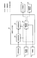
- the automatic focusing unit 119 includes an area dividing unit 200, an area selecting unit 201, a contrast calculating unit 202, a contrast determining unit 203, and a drive signal generating unit 204.
- the signal processing unit 116 is connected to the contrast calculating unit 202 via the area dividing unit 200 and the area selecting unit 201.
- the contrast calculation unit 202 is connected to the drive signal generation unit 204 via the contrast determination unit 203.
- the drive signal generation unit 204 is bi-directionally connected to the lens drive unit 105.
- the switching control unit 120 is connected to the drive signal generation unit 204.
- the control unit 122 is bi-directionally connected to the area division unit 200, the area selection unit 201, the contrast calculation unit 202, the contrast determination unit 203, and the drive signal generation unit 204.
- the automatic focusing unit 119 in the present embodiment uses, for example, the area division and contrast method disclosed in Patent Document 1.
- the video signal (captured image) from the signal processing unit 116 is transferred to the area division unit 200 based on the control of the control unit 122.
- the area division unit 200 divides the transferred video signal into block areas of a predetermined size based on the control of the control unit 122, and transfers the image signal to the area selection unit 201.
- the area selection unit 201 selects a block area to be focused on based on the transferred luminance distribution of each block area under the control of the control unit 122, and transfers the selected block area to the contrast calculation unit 202.
- the contrast calculating unit 202 calculates the contrast value regarding the transferred block area based on the control of the control unit 122, and transfers the calculated contrast value to the contrast judging unit 203.
- the contrast determination unit 203 compares the transferred contrast value with a predetermined threshold value based on the control of the control unit 122. If the transferred contrast value is lower than the threshold value, it is determined that the image is not in focus, and if it is higher, it is determined that the image is in focus. Only when it is determined that the in-focus state is not achieved, the control signal is transferred to the drive signal generation unit 204 so as to output the drive signal.
- the drive signal generation unit 204 confirms control signals from the switching control unit 120 and the contrast determination unit 203 based on the control of the control unit 122.
- the drive signal generation unit 204 transmits the focus object position to the lens drive unit 105. Transfer a drive signal to move the In the present embodiment, since the imaging system for bifocal switching shown in FIG. 3A is assumed, a drive signal for moving to an in-focus object position different from the current in-focus object position is output. The current in-focus object position is constantly transferred from the lens driving unit 105 as a position signal.
- the manual focusing unit 121 includes a movement amount setting unit 300, a movement amount reversing unit 301, and a drive signal generation unit 302.
- the movement amount setting unit 300 is connected to the movement amount inversion unit 301, and the movement amount inversion unit 301 is connected to the drive signal generation unit 302.
- the movement amount inverting unit 301 and the drive signal generating unit 302 are bi-directionally connected to the lens driving unit 105.
- the switching control unit 120 is connected to the drive signal generation unit 302.
- the control unit 122 is bi-directionally connected to the movement amount setting unit 300, the movement amount inversion unit 301, and the drive signal generation unit 302.
- the movement amount setting unit 300 sets the movement amount I for moving the in-focus object position of the optical system when the signal related to the activation of the endoscope apparatus is received from the switching control unit 120.
- the movement amount I 1 is set.
- the movement amount I may be set fixedly, or may be set arbitrarily by the user via the external I / F unit 123.
- the set movement amount I is transferred to the movement amount reverse unit 301.
- the movement amount reversing unit 301 determines whether the settable range is exceeded when the in-focus object position is moved from the current position by an amount corresponding to the movement amount I based on the control of the control unit 122. If it is determined to exceed, the sign of the movement amount I is inverted. Specifically, the movement amount I may be added to the ID representing the current in-focus object position, and the sign of the movement amount I may be reversed when deviating from the assumed number of stages of the in-focus object position. In this embodiment, since the imaging system of the bifocal switching shown in FIG. 3A is assumed, the sign is inverted when it is less than 0 or when it is more than 1.
- the current in-focus object position is constantly transferred from the lens driving unit 105 as a position signal.
- the movement amount I subjected to the above processing is transferred to the drive signal generation unit 302.
- the drive signal generation unit 302 confirms a control signal from the focus switch 109 via the control unit 122 or a control signal for activating the manual focus unit 121 from the switching control unit 120. When one of the control signals is confirmed, the drive signal generation unit 302 transfers a drive signal for moving the in-focus object position to the lens drive unit 105 by the movement amount I from the movement amount inversion unit 301.
- an endoscope apparatus can be provided. And the endoscope apparatus of this embodiment can switch to automatic focus control, without receiving the instruction
- FIG. 7 shows a configuration example of an endoscope apparatus of the present embodiment. Further, a detailed configuration example of the operation unit 102 included in the scope 100 is shown in FIG. As shown in FIG. 8, the operation unit 102 of this embodiment has a configuration in which the focus switch 109 of the one-step switch in the first embodiment shown in FIG. 1 is changed to the focus switch 400 of the two-step switch. It has become. Further, as shown in FIG. 7, the automatic focusing unit 119 of the contrast method is changed to the automatic focusing unit 401 of the phase difference method. Further, the elapsed time measuring unit 402 is newly added.
- the basic configuration is equivalent to that of the first embodiment, and the same name and number are assigned to the same configuration. Hereinafter, only different parts will be described.
- FIG. 8 is a detailed view of the operation unit 102 according to this embodiment, including an angle operation unit 107 for performing an angle operation of the tip end portion 101, an air supply / water supply switch 108 for controlling air supply and water supply, and focus control.
- a focus switch 400 for performing the operation is disposed.
- the signal processing unit 116 is connected to the output unit 117, the scene change detection unit 118, and the automatic focusing unit 401.
- the automatic focusing unit 401 is bi-directionally connected to the lens driving unit 105, and is also connected to the elapsed time measuring unit 402.
- the elapsed time measurement unit 402 is connected to the switching control unit 120.
- the control unit 122 is bi-directionally connected to the focus switch 400, the automatic focusing unit 401, and the elapsed time measuring unit 402.
- FIGS. 7 and 8 Basically, this embodiment is equivalent to the first embodiment, and only different parts will be described.
- the switching control unit 120 is based on the control signal from the focus switch 400 acquired via the control unit 122, the detection result of the scene change acquired from the scene change detection unit 118, and the elapsed time acquired from the elapsed time measurement unit 402. And control the start and stop of the automatic focusing unit 401 and the manual focusing unit 121.
- the automatic focusing unit 401 generates a drive signal for driving the lens driving unit 105, and performs focus adjustment of the lens system 103.
- a signal which is being activated is transferred to the elapsed time measuring unit 402 while the automatic focusing unit 401 is activated.
- the elapsed time measuring unit 402 does not measure time while the automatic focusing unit 401 is activated, and the automatic focusing unit 401 is stopped, and when the signal being activated is interrupted, the measurement of time is started. Then, the elapsed time measuring unit 402 continuously switches the measured time to the switching control unit 120. When the automatic focusing unit 401 is activated, the measured time is initialized to zero. Further, in the present embodiment, as shown in FIG. 3B, an imaging system of four-focus switching in which four-step switching is required to cover the range of pan focus is assumed.
- FIG. 9 shows a flowchart regarding the switching control performed by the switching control unit 120 and the focus control performed by the focus control unit 130.
- S21 and S22 are the same as S11 and S12 of FIG. 4, detailed description will be omitted.
- S23 it is determined whether or not the user has operated the focus switch 400 in the operation unit 102 (S23). However, unlike S13 of FIG. 4, in the present embodiment, a two-step switch is assumed as the focus switch 400.
- the focus switch 400 generates two types of control signals that move to the near point side when pulled to the front, and move to the far point side when pressed to the opposite side.
- the control signal is transferred to the switching control unit 120 via the control unit 122.
- the switching control unit 120 When the switching control unit 120 receives a control signal indicating that the focus switch 400 has been operated from the control unit 122, the switching control unit 120 stops the automatic focusing unit 401 and activates the manual focusing unit 121 (S24). Further, the switching control unit 120 outputs, to the manual focusing unit 121, a control signal for moving the in-focus object position by the movement amount I or -I.
- the manual focusing unit 121 moves the in-focus object position by the movement amount I or -I based on the control from the switching control unit 120 (S25).
- the movement amount I is set to 1 after using the imaging system for four-focus switching shown in FIG. 3 (B).
- the focus switch 400 is pulled to the front, the movement amount is ⁇ I because the movement is to the near point side.
- the focus switch 400 is pressed to the opposite side, the amount of movement is I since it moves to the far point side.
- the in-focus object position after movement exceeds the assumed number of stages of the in-focus object position of 3 or below 0, the sign of the movement amount I is inverted.
- the operation to the far point (near point) is performed by the user for the purpose of moving to the near point (far point) in the opposite direction. Since such behavior may confuse the user, the sign inversion of the movement amount I may not be performed in some cases.
- the focus switch 400 in S26 it is determined whether or not a scene change has been detected and whether a predetermined time has elapsed during execution of the manual focus control (S27).
- the scene change detection unit 118 detects such a scene change and transfers the detection result to the switching control unit 120. Further, the elapsed time measurement unit 402 transfers the elapsed time after the automatic focusing unit 401 is stopped to the switching control unit 120.
- the switching control unit 120 determines whether the control signal related to the detection of the scene change is transferred from the scene change detection unit 118 and whether the elapsed time after the auto focus unit 401 has stopped exceeds a predetermined time (S27), In the case, the process returns to S22 and the manual focusing unit 121 is stopped and the automatic focusing unit 401 is activated. In the case of No at S27, the current focus object position is maintained by manual focus control.
- the automatic focusing unit 401 includes a pixel selection unit 500, a phase difference detection unit 501, and a drive signal generation unit 502.
- the signal processing unit 116 is connected to the phase difference detection unit 501 via the pixel selection unit 500.
- the phase difference detection unit 501 is connected to the drive signal generation unit 502.
- the drive signal generation unit 502 is bi-directionally connected to the lens drive unit 105.
- the drive signal generation unit 502 is connected to the elapsed time measurement unit 402.
- the switching control unit 120 is connected to the drive signal generation unit 502.
- the control unit 122 is bidirectionally connected to the pixel selection unit 500, the phase difference detection unit 501, and the drive signal generation unit 502.
- the automatic focusing unit 401 in the present embodiment example uses, for example, a phase difference method in which pixels for phase difference detection are provided in an imaging device disclosed in Patent Document 2.
- the video signal from the signal processing unit 116 is transferred to the pixel selection unit 500 under the control of the control unit 122.
- the pixel selection unit 500 selects a pixel for phase difference detection in the imaging device based on the control of the control unit 122, and transfers the pixel to the phase difference detection unit 501.
- the phase difference detection unit 501 detects phase difference information from the transferred pixels for phase difference detection based on the control of the control unit 122, and obtains a movement amount for focusing and its direction (positive / negative sign).
- the control signal is transferred to the drive signal generation unit 502 so as to output the drive signal including the movement amount and the direction thereof.
- the drive signal generation unit 502 confirms control signals from the switching control unit 120 and the phase difference detection unit 501 based on the control of the control unit 122.
- the drive signal generation unit 502 sends the lens drive unit 105 a focused object position. Transfer a drive signal to move the
- the manual focus control can be switched to the desired position only by operating the two-step changeover switch.
- An endoscope apparatus can be provided.
- the endoscope apparatus according to the present embodiment switches to automatic focus control without receiving an instruction from the user when a predetermined time has elapsed from the start of the manual focus control and a scene change occurs.
- the user can adjust the in-focus object position only by operating the two-step changeover switch without being aware of switching between the automatic focus control and the manual focus control, and an endoscope apparatus with good operability can be provided.
- switching to automatic focus control does not occur in a short time due to halation or the like that occurs instantaneously, and it is possible to provide an endoscope apparatus that performs highly stable focus control.
- the endoscope apparatus controls the optical system (lens system 103 of FIG. 2A, etc.) to control the in-focus object position. It includes a focus control unit 130, a switching control unit 120 that switches control of the focus control unit 130 between automatic focusing and manual focusing, and an operation unit 102 that receives an operation from a user. Then, when the operation unit 102 receives an operation during a period in which the focus control unit 130 is performing automatic focusing, the switching control unit 120 switches the control in the focus control unit 130 to manual focus, and the focus control unit 130 Moves the in-focus object position to a position different from that at the time of the operation reception.
- the focus control unit 130 controls the in-focus object position, but in view of the correspondence between the in-focus object position and the state of the optical system (in particular, the position of the lens), It is envisaged to control the position.
- the lens position control is performed by outputting a control signal to the lens drive unit 105 or the like.
- the focus control unit 130 includes an automatic focusing unit 119 and a manual focusing unit 121.
- exclusive control is performed such that one of them operates and the other stops. That is, the switching control by the switching control unit 120 is basically the control of stopping the currently operating one of the automatic focusing unit 119 and the manual focusing unit 121 and activating the other.
- both switching from automatic focusing to manual focusing by the switching control unit 120 and movement of the in-focus object position by the focusing control unit 130 are performed.
- the operation received by the operation unit 102 does not need to be divided into an operation for the switching control unit 120 and an operation for the focus control unit 130. That is, in the present embodiment, the switching from the automatic focusing to the manual focusing is performed by the switching control unit 120 by the first operation, and the second operation different from the first operation is performed on the in-focus object position by the focus control unit 130.
- the movement is not performed, and the above two processes will both be performed when a given operation is performed.
- one operation means an operation of a unit that can be regarded as one type for the user, for example, a single press of a button, an operation of pushing down a lever once, or one rotation of a dial (the amount of rotation is arbitrary). ) May be an operation.
- one process is performed with a plurality of depressions, as in the case of double-clicking a mouse, such an operation is also included in one operation of this embodiment. That is, an operation that is not further decomposed and interpreted in the processing system may be considered as one operation in the present embodiment.
- the focus control unit 130 selects the in-focus object position. It may be moved to a position different from that at the time of receiving the operation.
- the operation received by the operation unit 102 is assumed to be the same as the above-described operation for performing both the switching from automatic to manual and the movement of the in-focus object position.
- the endoscope apparatus may include a scene change detection unit 118 that detects a scene change based on a captured video signal. Then, when a scene change is detected after switching from the automatic focusing to the manual focusing by the switching control unit 120, the switching control unit 120 switches the control in the focus control unit 130 from the manual focusing to the automatic focusing. .
- a change in a region to be imaged in a living body is also broadly included in a scene change.
- the scene may change when the site being imaged changes from the stomach to the small intestine or from the small intestine to the large intestine.
- the site may be set finely so as to divide the large intestine into a transverse colon and a descending colon. In this case, it is conceivable that the scene change is performed based on the color of the video signal.
- the scene is detected from the motion vector, the luminance, the change of the color and the like.
- the relative change between the subject and the imaging unit may be a scene change when the positional relationship changes.
- the relative positional relationship may be a relative distance between the imaging unit and the subject, or may be an angle between the wall surface and the optical axis of the imaging unit when the subject is regarded as a wall surface. That is, the presence or absence of a scene change is considered based on whether it is approaching or facing directly. In this case, it is conceivable to detect a scene change from the luminance change or the like.
- the region of interest is also present at a position (rear side) far from a position (front side) close to the imaging unit.
- a scene change is detected when a part, an object, a relative positional relationship, or the like changes. Therefore, when a scene change is detected, the scene change is detected in the depth direction of the region of interest. It is assumed that the distribution is also changing.
- the operation unit 102 may have a one-step switch (focus switch 109).
- the one-stage changeover switch is a switch that is turned on and off by a single operation by the user.
- the above control can be performed by a simple operation of one operation of the one-stage changeover switch. This is particularly effective in the bifocal switching shown in FIG.
- the operation unit 102 may have a two-step switch (focus switch 400).
- the two-stage changeover switch is a switch in which movement from the steady position to the first position or movement from the steady position to the second position is performed by one operation by the user. Then, when the two-step switch is moved to the first position, the focus control unit 130 moves the in-focus object position to the first in-focus object position. When the two-step switch is moved to the second position, the in-focus object position is moved to the second in-focus object position.
- the first position is a position different from the steady position
- the second position is a position different from the steady position and the first position.
- the first in-focus object position and the second in-focus object position are positions different from the in-focus object position at the time of operation reception, and one is closer to the far point than the in-focus object position at the time of operation reception And the other is the near point side.
- the movement direction of the in-focus object position can be designated by one operation. This is particularly effective when there are a large number of in-focus object positions that can be set, as in four-focus switching in FIG. 3B.
- the endoscope apparatus includes the focus control unit 130, the switching control unit 120, the operation unit 102, and the scene change detection unit 118. Then, when the focus control unit 130 is performing automatic focusing, the switching control unit 120 switches to manual focus when the operation unit receives an operation. In addition, when the focus control unit 130 performs manual focusing, the switching control unit 120 switches to automatic focusing when a scene change is detected by the scene change detection unit 118.
- the endoscope apparatus may include an elapsed time measurement unit 402 that measures an elapsed time after the focus control is switched to the manual focus by the switching control unit 120.
- the switching control unit 120 detects a scene change, and switches the control in the focus control unit 130 to the automatic focusing when the elapsed time is greater than a given threshold. .
- the elapsed time is used because it is difficult to think of a case where the diagnosis and the like are ended immediately after switching to the manual focus (that is, the user intentionally changes the scene).
- the reason for switching to the manual focus is because there is a dissatisfaction with the current focus state, and the dissatisfaction is because it is thought that there is nothing more than a region of interest to be a target of diagnosis and observation in the captured image .
- the switching control unit 120 may set the control of the focus control unit 130 to automatic focusing when the endoscope apparatus is activated.
- Automatic focus has the advantage of being able to reduce the burden on the user compared to manual focus, so that it is advantageous to use automatic focus positively.
- the focus control unit 130 may include a contrast calculation unit 202 that calculates a contrast value from a captured image, and a drive signal generation unit 204 that outputs a drive signal to drive an optical system based on the calculated contrast value.
- the focus control unit 130 includes the automatic focusing unit 119 illustrated in FIG. 5, and the automatic focusing unit 119 includes the above-described units.
- the focus control unit 130 may include a phase difference detection unit 501 that detects phase difference information from a captured image, and a drive signal generation unit 502 that outputs a drive signal for driving an optical system based on the detected phase difference information. May be included.
- the focus control unit 130 includes the automatic focusing unit 401 shown in FIG. 10, and the automatic focusing unit 401 includes the above-described units.
- the focus control unit 130 performs automatic focusing based on the above-described drive signal.
- contrast AF as a method of automatic focusing, and also to use phase difference AF.
- a combination of a configuration not including the elapsed time measurement unit 402 and the contrast AF is described
- a combination of the configuration including the elapsed time measurement unit 402 and the phase difference AF is described.
- the combination of the presence or absence of the elapsed time measurement unit 402 and the AF method is arbitrary. Also, the combination of the value of N and the AF method in discrete N focus switching is optional.
- the focus control unit 130 performs control to select any one of the first to N (N is an integer of 2 or more (including its value)) in-focus object positions set discretely. You may go.
- the focus control unit 130 may include a movement amount setting unit 300 that sets movement amount information indicating a fluctuation amount of the in-focus object position when the operation unit 102 receives an operation.
- the manual focusing unit 121 includes the movement amount setting unit 300.
- the focus control unit 130 sets the in-focus object position to the i-th according to the operation received by the operation unit 102.
- the in-focus object position is changed to the (i + k) -th in-focus object position.
- the movement amount setting unit 300 may set information specifying -k as the movement amount information. Then, in response to the operation received by the operation unit 102, the focus control unit 130 changes the in-focus object position from the ith in-focus object position to the i-k in-focus object position.
- the movement amount setting unit 300 may set information specifying 1 or -1 as the movement amount information k.
- the movement amount setting unit 300 may set movement amount information k based on an input from the outside.
- the movement amount information k can be set from the user or another system other than the endoscope apparatus.
- the focus control unit 130 may change the in-focus object position from the ith in-focus object position to the (i + k) in-focus object position.
- both the switching to the manual focus and the movement of the in-focus object position (specifically, movement corresponding to the movement amount information k) can be performed by the operation on the operation unit 102.
- the advantages and the like are as described above, the detailed description will be omitted.
- the operation unit 102 in the above-described endoscope apparatus may have a single-stage changeover switch (focus switch 109).
- a two-step switch (focus switch 400) may be provided. Each switch is as described above.
- the focus control unit 130 changes the corresponding to the movement amount information k with respect to the in-focus object position when the two-step switch is moved to the first position. Control is performed, and when the two-step switch is moved to the second position, control is performed to change the focusing object position in accordance with -k determined the sign of the moving amount information k. .
- the control for changing the movement to the far point side and the movement to the near point side according to the operation direction of the switch is described using the movement amount information, and is substantially as described above. Therefore, detailed description is omitted.
- an operation receiving unit that receives an operation of the endoscope apparatus having an optical system capable of controlling the in-focus object position from the user, an output unit that outputs an operation signal according to the operation
- the present invention is also applicable to an endoscope apparatus operating device including the above.
- the output unit outputs an operation signal instructing switching from automatic focusing to manual focusing by the user's operation on the operation receiving unit, and an operation instructing movement to a position different from that at the time of operation reception of the in-focus object position. Output a signal.
- the operation accepted by the operation accepting unit may be the “one-time operation” described above.
- the endoscope apparatus operation device corresponds to, for example, the operation unit 102 in FIG. 2B
- the operation reception unit corresponds to the focus switch 109 (or the focus switch 400 in the operation unit 102 in FIG. 8).
- the output unit (not shown in FIG. 2B or the like) outputs an operation signal to a block that performs processing of the endoscope apparatus.
- the operation signal is output to the control unit 122 in FIG. It is also good.
- one mechanism such as a switch
- the configuration can be simplified. become.
- the operation reception unit performs a first operation performing both switching from automatic focusing to manual focusing and movement of the in-focus object position, and movement of the in-focus object position after switching to manual focusing. Both of the two operations may be accepted.
- the operation receiving unit may be a one-step switch, and may receive the first operation and the second operation by operating the one-step switch.
- both the first operation and the second operation can be performed by the one-step changeover switch as shown in FIG. 2B, and effective focus control can be performed with a simple configuration.
- the third operation of performing both the switching from the automatic focusing to the manual focusing and the change to increase the distance from the optical system to the in-focus object position, the switching from the automatic focusing to the manual focusing, and the merging from the optical system may receive both the third operation and the fourth operation in consideration of the fourth operation for performing both of the changes to reduce the distance to the in-focus object position.
- the operation reception unit may receive the fifth operation and the sixth operation in addition to the third operation and the fourth operation.
- the operation receiving unit may be a two-step switch, and may receive third to sixth operations by operating the two-step switch.
- both the third to sixth operations and the second operation can be performed by the two-step switch as shown in FIG. 8, and effective focus control with a simple configuration becomes possible.
- the present invention is not limited to the embodiments 1 to 2 or their modifications as they are, and the implementation stage Then, the components can be modified and embodied without departing from the scope of the invention. Further, various inventions can be formed by appropriately combining a plurality of constituent elements disclosed in the above-described first and second embodiments and the modification. For example, some components may be deleted from all the components described in each of the first and second embodiments and the modifications. Furthermore, the components described in different embodiments and modifications may be combined as appropriate. Further, in the specification or the drawings, the terms described together with the broader or synonymous different terms at least once can be replaced with the different terms anywhere in the specification or the drawings. Thus, various modifications and applications are possible without departing from the spirit of the invention.
Abstract
L'invention concerne un appareil endoscopique, un dispositif d'actionnement pour un appareil endoscopique, un procédé de commande pour un appareil endoscopique et similaires, qui aboutissent à une simplification de la commutation entre une commande de focalisation automatique et une commande de focalisation manuelle. Un appareil endoscopique selon l'invention comprend : une unité de commande de focalisation (130) qui commande une position d'objet mis au point par la commande d'un système optique; une unité de commande de commutation (120) qui commute la commande dans l'unité de commande de focalisation (130) entre une focalisation automatique et une focalisation manuelle; et une unité d'actionnement (102) qui accepte un actionnement par un utilisateur. Lorsque l'unité d'actionnement (102) accepte l'actionnement par l'utilisateur alors que la focalisation automatique est effectuée dans l'unité de commande de focalisation (130), l'unité de commande de commutation (120) commute la commande dans l'unité de commande de focalisation (130) de la focalisation automatique à la focalisation manuelle, et l'unité de commande de focalisation (130) effectue une commande pour déplacer la position d'objet mis au point dans une position différente de celle lorsque l'actionnement a été accepté.
Priority Applications (3)
| Application Number | Priority Date | Filing Date | Title |
|---|---|---|---|
| CN201280067108.1A CN104053392B (zh) | 2012-01-17 | 2012-12-28 | 内窥镜装置和内窥镜装置的控制方法 |
| EP12866184.0A EP2805665A4 (fr) | 2012-01-17 | 2012-12-28 | Appareil endoscopique, dispositif d'actionnement pour appareil endoscopique et procédé de commande pour appareil endoscopique |
| US14/312,143 US9645473B2 (en) | 2012-01-17 | 2014-06-23 | Endoscope apparatus and control method for endoscope apparatus |
Applications Claiming Priority (2)
| Application Number | Priority Date | Filing Date | Title |
|---|---|---|---|
| JP2012-006983 | 2012-01-17 | ||
| JP2012006983A JP5988590B2 (ja) | 2012-01-17 | 2012-01-17 | 内視鏡装置 |
Related Child Applications (1)
| Application Number | Title | Priority Date | Filing Date |
|---|---|---|---|
| US14/312,143 Continuation US9645473B2 (en) | 2012-01-17 | 2014-06-23 | Endoscope apparatus and control method for endoscope apparatus |
Publications (1)
| Publication Number | Publication Date |
|---|---|
| WO2013108580A1 true WO2013108580A1 (fr) | 2013-07-25 |
Family
ID=48799015
Family Applications (1)
| Application Number | Title | Priority Date | Filing Date |
|---|---|---|---|
| PCT/JP2012/084173 WO2013108580A1 (fr) | 2012-01-17 | 2012-12-28 | Appareil endoscopique, dispositif d'actionnement pour appareil endoscopique et procédé de commande pour appareil endoscopique |
Country Status (5)
| Country | Link |
|---|---|
| US (1) | US9645473B2 (fr) |
| EP (1) | EP2805665A4 (fr) |
| JP (1) | JP5988590B2 (fr) |
| CN (1) | CN104053392B (fr) |
| WO (1) | WO2013108580A1 (fr) |
Cited By (1)
| Publication number | Priority date | Publication date | Assignee | Title |
|---|---|---|---|---|
| US20160234427A1 (en) * | 2013-12-27 | 2016-08-11 | Olympus Corporation | Endoscope apparatus, method for controlling endoscope apparatus, and information storage device |
Families Citing this family (15)
| Publication number | Priority date | Publication date | Assignee | Title |
|---|---|---|---|---|
| JP6103849B2 (ja) * | 2012-08-02 | 2017-03-29 | オリンパス株式会社 | 内視鏡装置及び内視鏡装置の作動方法 |
| CN107005647B (zh) * | 2014-12-02 | 2020-08-11 | 奥林巴斯株式会社 | 对焦控制装置、内窥镜装置以及对焦控制装置的控制方法 |
| DE112015005847T5 (de) * | 2015-01-23 | 2017-09-14 | Olympus Corporation | Endoskopvorrichtung und Scharfeinstellungssteuerungsverfahren für Endoskopvorrichtung |
| JP6530067B2 (ja) * | 2015-06-11 | 2019-06-12 | オリンパス株式会社 | 内視鏡装置及び内視鏡装置の作動方法 |
| JP6762313B2 (ja) | 2015-10-27 | 2020-09-30 | オリンパス株式会社 | 撮像装置、内視鏡装置及び撮像装置の作動方法 |
| US10817597B2 (en) | 2016-04-20 | 2020-10-27 | Servicenow, Inc. | Operational scoping with access restrictions |
| JP2018036507A (ja) * | 2016-08-31 | 2018-03-08 | キヤノン株式会社 | レンズ制御装置、その制御方法 |
| US10832189B2 (en) | 2017-05-05 | 2020-11-10 | Servicenow, Inc. | Systems and methods for dynamically scheduling tasks across an enterprise |
| US10938663B2 (en) | 2018-05-07 | 2021-03-02 | Servicenow, Inc. | Discovery and management of devices |
| US10819586B2 (en) | 2018-10-17 | 2020-10-27 | Servicenow, Inc. | Functional discovery and mapping of serverless resources |
| US11126597B2 (en) | 2019-01-17 | 2021-09-21 | Servicenow, Inc. | Efficient database table rotation and upgrade |
| US11150954B2 (en) | 2019-02-04 | 2021-10-19 | Servicenow, Inc. | Mitigating resource scheduling conflicts in a cloud platform |
| US10924344B2 (en) | 2019-04-11 | 2021-02-16 | Servicenow, Inc. | Discovery and mapping of cloud-based resource modifications |
| US11202013B2 (en) * | 2020-01-30 | 2021-12-14 | Canon Kabushiki Kaisha | Control apparatus, lens apparatus, imaging apparatus, control method, and non-transitory computer-readable storage medium |
| WO2023042354A1 (fr) * | 2021-09-16 | 2023-03-23 | オリンパスメディカルシステムズ株式会社 | Processeur d'endoscope, programme et procédé de commande de lentille de focalisation |
Citations (8)
| Publication number | Priority date | Publication date | Assignee | Title |
|---|---|---|---|---|
| JPH11103409A (ja) * | 1997-09-29 | 1999-04-13 | Fuji Photo Optical Co Ltd | テレビレンズのフォーカス操作装置 |
| JP2004064713A (ja) * | 2002-07-31 | 2004-02-26 | Canon Inc | 撮像装置 |
| JP2006288432A (ja) * | 2005-04-05 | 2006-10-26 | Olympus Medical Systems Corp | 電子内視鏡 |
| JP2008064980A (ja) * | 2006-09-06 | 2008-03-21 | Canon Inc | 光学装置、光学装置の制御方法 |
| JP2008205642A (ja) * | 2007-02-16 | 2008-09-04 | Fujinon Corp | レンズシステム及びフォーカス操作装置 |
| JP2009142586A (ja) | 2007-12-18 | 2009-07-02 | Fujinon Corp | 内視鏡システムの自動焦点調整方法および内視鏡システム |
| JP2011059337A (ja) | 2009-09-09 | 2011-03-24 | Fujifilm Corp | 撮像装置 |
| JP2011139760A (ja) | 2010-01-06 | 2011-07-21 | Olympus Medical Systems Corp | 内視鏡システム |
Family Cites Families (3)
| Publication number | Priority date | Publication date | Assignee | Title |
|---|---|---|---|---|
| CA2567737A1 (fr) | 2004-05-14 | 2005-11-24 | Olympus Medical Systems Corp. | Endoscope electronique |
| JP4377745B2 (ja) * | 2004-05-14 | 2009-12-02 | オリンパス株式会社 | 電子内視鏡 |
| DE102008031054A1 (de) * | 2008-01-14 | 2009-07-16 | Kaltenbach & Voigt Gmbh | Zahnärztliche Intraoralkamera |
-
2012
- 2012-01-17 JP JP2012006983A patent/JP5988590B2/ja active Active
- 2012-12-28 EP EP12866184.0A patent/EP2805665A4/fr not_active Withdrawn
- 2012-12-28 WO PCT/JP2012/084173 patent/WO2013108580A1/fr active Application Filing
- 2012-12-28 CN CN201280067108.1A patent/CN104053392B/zh not_active Expired - Fee Related
-
2014
- 2014-06-23 US US14/312,143 patent/US9645473B2/en active Active
Patent Citations (8)
| Publication number | Priority date | Publication date | Assignee | Title |
|---|---|---|---|---|
| JPH11103409A (ja) * | 1997-09-29 | 1999-04-13 | Fuji Photo Optical Co Ltd | テレビレンズのフォーカス操作装置 |
| JP2004064713A (ja) * | 2002-07-31 | 2004-02-26 | Canon Inc | 撮像装置 |
| JP2006288432A (ja) * | 2005-04-05 | 2006-10-26 | Olympus Medical Systems Corp | 電子内視鏡 |
| JP2008064980A (ja) * | 2006-09-06 | 2008-03-21 | Canon Inc | 光学装置、光学装置の制御方法 |
| JP2008205642A (ja) * | 2007-02-16 | 2008-09-04 | Fujinon Corp | レンズシステム及びフォーカス操作装置 |
| JP2009142586A (ja) | 2007-12-18 | 2009-07-02 | Fujinon Corp | 内視鏡システムの自動焦点調整方法および内視鏡システム |
| JP2011059337A (ja) | 2009-09-09 | 2011-03-24 | Fujifilm Corp | 撮像装置 |
| JP2011139760A (ja) | 2010-01-06 | 2011-07-21 | Olympus Medical Systems Corp | 内視鏡システム |
Non-Patent Citations (1)
| Title |
|---|
| See also references of EP2805665A4 |
Cited By (2)
| Publication number | Priority date | Publication date | Assignee | Title |
|---|---|---|---|---|
| US20160234427A1 (en) * | 2013-12-27 | 2016-08-11 | Olympus Corporation | Endoscope apparatus, method for controlling endoscope apparatus, and information storage device |
| US10574874B2 (en) * | 2013-12-27 | 2020-02-25 | Olympus Corporation | Endoscope apparatus, method for controlling endoscope apparatus, and information storage device |
Also Published As
| Publication number | Publication date |
|---|---|
| US9645473B2 (en) | 2017-05-09 |
| CN104053392B (zh) | 2016-09-07 |
| CN104053392A (zh) | 2014-09-17 |
| US20140300716A1 (en) | 2014-10-09 |
| JP2013146289A (ja) | 2013-08-01 |
| EP2805665A1 (fr) | 2014-11-26 |
| EP2805665A4 (fr) | 2015-04-08 |
| JP5988590B2 (ja) | 2016-09-07 |
Similar Documents
| Publication | Publication Date | Title |
|---|---|---|
| WO2013108580A1 (fr) | Appareil endoscopique, dispositif d'actionnement pour appareil endoscopique et procédé de commande pour appareil endoscopique | |
| US9594291B2 (en) | Lens apparatus and image pickup apparatus including the same | |
| WO2013027460A1 (fr) | Dispositif de commande de mise au point, dispositif endoscopique et procédé de commande de mise au point | |
| US20100238321A1 (en) | Camera body, interchangeable lens unit, and camera system | |
| JP5474528B2 (ja) | オートフォーカスシステム | |
| US9083878B2 (en) | Focus adjustment unit and camera system | |
| WO2013058145A1 (fr) | Dispositif d'imagerie, dispositif d'endoscope et procédé de commande de dispositif d'imagerie | |
| JP5857160B2 (ja) | 内視鏡用の撮像システム、内視鏡用の撮像システムの作動方法 | |
| US8032019B2 (en) | Camera body and imaging apparatus | |
| JP2001004909A (ja) | 自動焦点調節装置を有するカメラ | |
| JP2008102207A (ja) | レンズ装置及び撮像装置 | |
| JP6525813B2 (ja) | 撮像装置、制御方法、プログラム及び記憶媒体 | |
| CN112153276B (zh) | 摄像装置 | |
| JP5171105B2 (ja) | 撮影装置及び交換レンズ式撮影装置、交換レンズユニット | |
| JP6834988B2 (ja) | 制御装置 | |
| JP5430314B2 (ja) | 撮像装置及びその制御方法 | |
| JP4585338B2 (ja) | 撮像装置 | |
| US11962888B2 (en) | Imaging apparatus with focus operation display information | |
| JP2018014601A (ja) | 像ブレ補正装置及び方法、及び撮像装置 | |
| JP2020003759A (ja) | 焦点調節装置およびその制御方法 | |
| JP2006084999A (ja) | Afエリア操作システム | |
| CN117714827A (zh) | 镜头装置和摄像装置 | |
| JP2011075735A (ja) | 撮像装置 | |
| JPH02134607A (ja) | 自動焦点調節装置 | |
| JP2018146606A (ja) | 画像処理装置、撮像装置および制御方法 |
Legal Events
| Date | Code | Title | Description |
|---|---|---|---|
| 121 | Ep: the epo has been informed by wipo that ep was designated in this application |
Ref document number: 12866184 Country of ref document: EP Kind code of ref document: A1 |
|
| WWE | Wipo information: entry into national phase |
Ref document number: 2012866184 Country of ref document: EP |
|
| NENP | Non-entry into the national phase |
Ref country code: DE |