WO2013108580A1 - 内視鏡装置、内視鏡装置用操作装置及び内視鏡装置の制御方法 - Google Patents
内視鏡装置、内視鏡装置用操作装置及び内視鏡装置の制御方法 Download PDFInfo
- Publication number
- WO2013108580A1 WO2013108580A1 PCT/JP2012/084173 JP2012084173W WO2013108580A1 WO 2013108580 A1 WO2013108580 A1 WO 2013108580A1 JP 2012084173 W JP2012084173 W JP 2012084173W WO 2013108580 A1 WO2013108580 A1 WO 2013108580A1
- Authority
- WO
- WIPO (PCT)
- Prior art keywords
- focus
- unit
- control
- control unit
- object position
- Prior art date
Links
Images


Classifications
-
- A—HUMAN NECESSITIES
- A61—MEDICAL OR VETERINARY SCIENCE; HYGIENE
- A61B—DIAGNOSIS; SURGERY; IDENTIFICATION
- A61B1/00—Instruments for performing medical examinations of the interior of cavities or tubes of the body by visual or photographical inspection, e.g. endoscopes; Illuminating arrangements therefor
- A61B1/00002—Operational features of endoscopes
- A61B1/00004—Operational features of endoscopes characterised by electronic signal processing
- A61B1/00006—Operational features of endoscopes characterised by electronic signal processing of control signals
-
- A—HUMAN NECESSITIES
- A61—MEDICAL OR VETERINARY SCIENCE; HYGIENE
- A61B—DIAGNOSIS; SURGERY; IDENTIFICATION
- A61B1/00—Instruments for performing medical examinations of the interior of cavities or tubes of the body by visual or photographical inspection, e.g. endoscopes; Illuminating arrangements therefor
- A61B1/00163—Optical arrangements
- A61B1/00188—Optical arrangements with focusing or zooming features
-
- G—PHYSICS
- G02—OPTICS
- G02B—OPTICAL ELEMENTS, SYSTEMS OR APPARATUS
- G02B23/00—Telescopes, e.g. binoculars; Periscopes; Instruments for viewing the inside of hollow bodies; Viewfinders; Optical aiming or sighting devices
- G02B23/24—Instruments or systems for viewing the inside of hollow bodies, e.g. fibrescopes
- G02B23/2476—Non-optical details, e.g. housings, mountings, supports
- G02B23/2484—Arrangements in relation to a camera or imaging device
-
- G—PHYSICS
- G03—PHOTOGRAPHY; CINEMATOGRAPHY; ANALOGOUS TECHNIQUES USING WAVES OTHER THAN OPTICAL WAVES; ELECTROGRAPHY; HOLOGRAPHY
- G03B—APPARATUS OR ARRANGEMENTS FOR TAKING PHOTOGRAPHS OR FOR PROJECTING OR VIEWING THEM; APPARATUS OR ARRANGEMENTS EMPLOYING ANALOGOUS TECHNIQUES USING WAVES OTHER THAN OPTICAL WAVES; ACCESSORIES THEREFOR
- G03B13/00—Viewfinders; Focusing aids for cameras; Means for focusing for cameras; Autofocus systems for cameras
- G03B13/32—Means for focusing
- G03B13/34—Power focusing
- G03B13/36—Autofocus systems
-
- H—ELECTRICITY
- H04—ELECTRIC COMMUNICATION TECHNIQUE
- H04N—PICTORIAL COMMUNICATION, e.g. TELEVISION
- H04N23/00—Cameras or camera modules comprising electronic image sensors; Control thereof
- H04N23/50—Constructional details
- H04N23/555—Constructional details for picking-up images in sites, inaccessible due to their dimensions or hazardous conditions, e.g. endoscopes or borescopes
-
- H—ELECTRICITY
- H04—ELECTRIC COMMUNICATION TECHNIQUE
- H04N—PICTORIAL COMMUNICATION, e.g. TELEVISION
- H04N23/00—Cameras or camera modules comprising electronic image sensors; Control thereof
- H04N23/60—Control of cameras or camera modules
- H04N23/67—Focus control based on electronic image sensor signals
- H04N23/672—Focus control based on electronic image sensor signals based on the phase difference signals
-
- H—ELECTRICITY
- H04—ELECTRIC COMMUNICATION TECHNIQUE
- H04N—PICTORIAL COMMUNICATION, e.g. TELEVISION
- H04N23/00—Cameras or camera modules comprising electronic image sensors; Control thereof
- H04N23/60—Control of cameras or camera modules
- H04N23/67—Focus control based on electronic image sensor signals
- H04N23/673—Focus control based on electronic image sensor signals based on contrast or high frequency components of image signals, e.g. hill climbing method
-
- A—HUMAN NECESSITIES
- A61—MEDICAL OR VETERINARY SCIENCE; HYGIENE
- A61B—DIAGNOSIS; SURGERY; IDENTIFICATION
- A61B1/00—Instruments for performing medical examinations of the interior of cavities or tubes of the body by visual or photographical inspection, e.g. endoscopes; Illuminating arrangements therefor
- A61B1/00002—Operational features of endoscopes
- A61B1/00039—Operational features of endoscopes provided with input arrangements for the user
- A61B1/00042—Operational features of endoscopes provided with input arrangements for the user for mechanical operation
Definitions
- the present invention relates to an endoscope apparatus, an operation apparatus for an endoscope apparatus, a control method of an endoscope apparatus, and the like.
- Patent Document 1 discloses an endoscope apparatus that performs automatic focusing control using area division and a contrast method. As a result, the complexity of manually performing focus control is reduced, and operability can be improved.
- the imaging device which provides the pixel for phase difference detection in an image pick-up element, and performs an automatic focus control is disclosed.
- the configuration in which the pixels for phase difference detection are provided in the imaging device is compact, and it is considered that mounting on the tip of the endoscope is also possible. As a result, the speed of automatic focus control can be increased, and the operability can be improved.
- Patent Document 3 discloses an endoscope apparatus that switches between automatic focus control and manual focus control based on a luminance level, a magnification factor, and the like. As a result, it is possible to cope with a scene where automatic focus control is not good, and operability can be improved.
- JP 2011-139760 A JP, 2011-59337, A JP, 2009-142586, A
- Patent Document 1 and Patent Document 2 work well when the region of interest such as a lesion converges to one point, but when multiple regions of interest exist at the near point and the far point, or one region of interest is near There is a problem that can not be dealt with when there is a wide range from point to far point.
- Patent Document 3 switching between automatic focus control and manual focus control is limited. Therefore, even when the automatic focus control operates properly, there is a possibility that the manual focus control may be performed, and the switching of the focus control method by the system is only an auxiliary one. Therefore, there is a problem that it is necessary for the user to pay sufficient attention to the state of focus control in order to perform effective focus control.
- an endoscope apparatus an operation apparatus for an endoscope apparatus, a control method of an endoscope apparatus, and the like that simplify switching between automatic focus control and manual focus control. it can.
- switching by the system of automatic focus control and manual focus control, switching based on user operation of automatic focus control and manual focus control, and movement of the in-focus object position are efficiently performed.
- One aspect of the present invention is a focus control unit that controls an optical system to control an in-focus object position, an automatic focusing that automatically controls the in-focus object position, and a control by the focus control unit.
- a switching control unit for switching between manual focusing for manually controlling the in-focus object position, and an operation unit for receiving an operation from a user, in a period in which the automatic focusing is performed in the focus control unit;
- the switching control unit switches control in the focus control unit from the automatic focusing to the manual focusing, and the focus control unit is configured to receive the in-focus object.
- the present invention relates to an endoscope apparatus that performs control to move a position to a position different from that at the time of receiving the operation.
- the endoscope apparatus having a configuration for switching between automatic focus and manual focus
- switching to manual focus is performed.
- Movement of the in-focus object position is performed. Therefore, since the two processes can be performed by the common operation, the configuration of the operation unit can be simplified, and the burden on the user in focus control can be reduced.
- Another aspect of the present invention is a focus control unit that performs control of an optical system to control the in-focus object position, automatic focusing that automatically controls the in-focus object position, and control of the focus control unit.
- a scene that detects a scene change based on a switching control unit that switches between manual focusing in which the in-focus object position is manually controlled, an operation unit that receives an operation from a user, and a captured image captured by an imaging unit
- a change detection unit wherein the switching control unit controls the focus control when the operation unit receives the operation from the user when the automatic focusing is performed by the focus control unit. Switching the control in the unit to the manual focus, the manual control being performed by the focus control unit, the scene When the scene change is detected by the reduction detection unit, related to control in the focus control unit to an endoscope apparatus that switches to the automatic focusing.
- Another aspect of the present invention is an operation receiving unit that receives from a user an operation of an endoscope apparatus having an optical system capable of controlling an in-focus object position, and an output unit that outputs an operation signal according to the operation. And the output unit is configured to automatically switch the in-focus object position according to the user's operation on the operation reception unit, to switch to a manual focus in which the in-focus object position is manually controlled.
- the present invention relates to an operating device for an endoscope apparatus which outputs the operation signal to instruct and outputs the operation signal instructing movement of the in-focus object position to a position different from that at the time of the operation reception.
- Another aspect of the present invention is a control method of an endoscope apparatus which controls an optical system to control an in-focus object position, which receives an operation from a user and is based on the received operation from the user.
- Switching control for switching between the automatic focusing for automatically controlling the in-focus object position and the manual focusing for manually controlling the in-focus object position, and the in-focus object position being different from that at the time of reception of the operation
- the operation unit receives the operation from the user during the period in which the automatic focusing is performed in the focus control unit, the automatic focusing is performed from the automatic focusing as the switching control.
- the present invention relates to a control method of an endoscope apparatus that performs control to switch to manual focus.
- Another aspect of the present invention is a control method of an endoscope apparatus that controls an optical system to control the position of an in-focus object, and a reception process for receiving an operation from a user, and an image taken by an imaging unit
- An automatic focusing process for automatically controlling the in-focus object position based on at least one of a result of the reception process and a result of the scene change detection process, and a scene change detection process based on an image;
- the switching control is performed as the switching control when the operation from the user is received as a result of the receiving process.
- the control to switch from the automatic focusing to the manual focusing is performed, and the manual focusing is performed.
- Te when a scene change as a result of the scene change detection process is detected, as the switching control, related to the control method of an endoscope apparatus which performs control for switching from the manual focus control to the automatic focus.
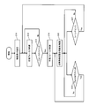
- FIG. 1 is a configuration example of the endoscope apparatus of the present embodiment.
- FIG. 2A shows an example of the configuration of the tip end
- FIG. FIGS. 3A and 3B are diagrams for explaining the relationship between the in-focus object position and the depth of field range in discrete focus control.
- FIG. 4 is a flowchart for explaining the processing of the present embodiment.
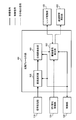
- FIG. 5 shows an example of the configuration of the automatic focusing unit.
- FIG. 6 shows an example of the configuration of the manual focusing unit.
- FIG. 7 shows another configuration example of the endoscope apparatus of the present embodiment.
- FIG. 8 shows another configuration example of the operation unit.
- FIG. 9 is another flowchart illustrating the process of the present embodiment.
- FIG. 10 shows another configuration example of the automatic focusing unit.
- switching between automatic focus control and manual focus control is considered essential. Therefore, the problem is an increase in the operation load of the user. If the user looks at the image taken and determines that the focus does not match the desired subject, some operation is performed. In the case of an endoscope apparatus that does not perform automatic focus control, movement of the in-focus object position (the position of the in-focus object. Details will be described later) may be considered. It is necessary to consider up to switching between control and manual focus control.
- the current state is the automatic focus control
- the automatic focus control it is considered that the automatic focus control does not work well in the current state, and the mode is switched to the manual focus control.
- the current focus control is manual focus control
- the automatic focus control should be tried, but if the automatic focus control has already been tried, as a result of the failure, etc., the in-focus object position is switched with the manual focus control.
- the user is forced to store the operation history, etc., and the load increases significantly.
- the present applicant proposes a method for realizing focus control which reduces the burden on the user by appropriately combining automatic switching of focus control, switching by the user, and movement of the in-focus object position.
- the control When a scene change is detected at the time of manual focus control, the control returns to the automatic focus control. Since the scene (the object to be imaged, etc.) has changed, there is a possibility that it will operate well after the change, even if the automatic focus control has not operated well before the change. That is, although it is unclear whether or not the automatic focus control works well after the scene change, it is control to actively shift to the automatic focus control. As a result, the possibility of performing automatic focus control is increased, and the burden on the user of focusing can be reduced. Even if the automatic focus control does not operate well after a scene change, it is only necessary to perform the given operation described above when the subject is not in focus, and that point does not lead to an increase in the burden.
- the automatic focus control method is contrast AF, and a scene change is used as a condition for switching from manual focus control to automatic focus control.
- the automatic focus control method is the phase difference AF, and in addition to the scene change, the elapsed time is considered as a condition for switching from the manual focus control to the automatic focus control.
- the combination of the automatic focus control method and the switching condition to the automatic focus control is optional.
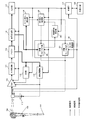
- FIG. 1 shows a configuration example of an endoscope apparatus according to the present embodiment.
- the scope 100 of the endoscope apparatus has a distal end portion 101 inserted into a living body, and an operation unit 102 that performs an angle operation and focus control of the distal end portion 101.
- FIG. 2A is a detailed configuration example of the distal end portion 101, and a video signal photographed through the lens system 103 and the CCD 104 in the distal end portion 101 is output.
- the lens system 103 is capable of focus adjustment, and a lens drive unit 105 such as a stepping motor for performing focus adjustment is provided. Further, in the vicinity of the lens system 103, an illumination lens system 106 for emitting illumination light is installed.
- FIG. 2B is a detailed configuration example of the operation unit 102, and an angle operation unit 107 for performing an angle operation of the tip end portion 101, an air supply / water supply switch 108 for controlling air supply and water supply, and focus control.
- a focus switch 109 for performing the operation is disposed.
- the endoscope apparatus of the present embodiment includes the components shown in FIG.
- the endoscope apparatus is not limited to the configuration of FIG. 1, and various modifications may be made such as omitting some of these components or adding other components.
- the video signal from the CCD 104 is amplified by the Gain 110 and converted into a digital signal by the A / D converter 111.
- the video signal from the A / D converter 111 is transferred to the WB unit 113, the photometric evaluation unit 114, and the signal processing unit 116 via the buffer 112.
- the WB unit 113 is connected to the Gain 110, and the photometric evaluation unit 114 is connected to the illumination light source 115 and the Gain 110.
- the illumination light from the illumination light source 115 is guided to an illumination lens system 106 provided at the distal end portion 101 of the scope 100 via an optical fiber, and is applied to an object to be an object.
- the signal processing unit 116 is connected to the output unit 117, the scene change detection unit 118, and the automatic focusing unit 119.
- the scene change detection unit 118 is connected to the switching control unit 120, and the switching control unit 120 is connected to the automatic focusing unit 119 and the manual focusing unit 121.
- the automatic focusing unit 119 and the manual focusing unit 121 are bi-directionally connected to the lens driving unit 105.
- the endoscope apparatus may include the focus control unit 130, and the focus control unit 130 may include the automatic focusing unit 119 and the manual focusing unit 121.
- a control unit 122 such as a microcomputer includes a CCD 104, an angle operation unit 107, an air / water switch 108, a focus switch 109, a gain 110, an A / D converter 111, a WB unit 113, a photometric evaluation unit 114, a signal processing unit 116, An output unit 117, a scene change detection unit 118, an automatic focusing unit 119, a switching control unit 120, and a manual focusing unit 121 are bi-directionally connected. Further, an external I / F unit 123 provided with a power switch and an interface for performing settings such as switching of various modes at the time of photographing is bi-directionally connected to the control unit 122.
- Activation of the power supply and setting of imaging conditions are performed via the external I / F unit 123.
- Video signals captured through the lens system 103 and the CCD 104 are continuously output as analog signals at predetermined time intervals. In the present embodiment, 1/60 seconds is assumed as the predetermined time interval.
- the CCD 104 a single plate CCD in which a bayer type primary color filter is disposed on the front side is assumed.
- a xenon light source is assumed as the illumination light source 115.
- the captured analog signal is amplified by a predetermined amount by Gain 110, converted into a digital signal by A / D converter 111, and transferred to buffer 112.
- the buffer 112 can record one video signal, and will be overwritten as it is taken.
- the video signal in the buffer 112 is intermittently transferred to the WB unit 113 and the photometric evaluation unit 114 at predetermined time intervals under the control of the control unit 122.
- the WB unit 113 integrates a signal of a predetermined level for each color signal corresponding to the color filter to calculate a white balance coefficient.
- the white balance coefficient is transferred to the Gain 110, and white balance is performed by multiplying different gain for each color signal.
- the photometric evaluation unit 114 controls the amplification factor of the gain 110, the light amount of the illumination light source 115, and the like so as to obtain appropriate exposure.
- the signal processing unit 116 reads a video signal in a single plate state and performs known interpolation processing, gradation processing, and the like.
- the processed video signal is transferred to the output unit 117.
- the output unit 117 may be, for example, a display unit such as a liquid crystal display or an organic EL display. In that case, the video signal (captured image) transferred from the signal processing unit 116 is sequentially displayed. Note that the output unit 117 may be configured to sequentially record and save in a recording medium such as a hard disk or a memory card.
- the processed video signal from the signal processing unit 116 is also transferred to the scene change detection unit 118 and the automatic focusing unit 119.
- the scene change detection unit 118 reads the processed video signal from the signal processing unit 116 at a predetermined time interval (1/60 second interval in this embodiment), and continuously outputs the video signal. Calculate the amount of change between As the amount of change, for example, a sum of absolute values of differences between luminance signals is used. When the amount of change exceeds a predetermined threshold value, it is determined that a scene change is detected. The detection result of the scene change is transferred to the switching control unit 120.
- the switching control unit 120 switches the focus control performed by the focus control unit 130 based on the control signal from the focus switch 109 via the control unit 122 and the detection result of the scene change from the scene change detection unit 118. Specifically, control is performed to activate and stop the automatic focusing unit 119 and the manual focusing unit 121. The automatic focusing unit 119 and the manual focusing unit 121 are controlled to operate mutually exclusively. The automatic focusing unit 119 and the manual focusing unit 121 generate a drive signal for driving the lens drive unit 105, and perform focus adjustment of the lens system 103.
- FIG. 3A is an explanatory view of the in-focus object position and the depth of field range in this embodiment.
- about 5 to 70 mm is required as a range of pan focus in an endoscope.
- a two-focus switching imaging system is assumed in which two-step switching is required to cover the pan focus range.
- the drive signals generated from the automatic focusing unit 119 and the manual focusing unit 121 designate either 0 on the near point side or 1 on the far point side.
- the number of stages of the in-focus object position varies depending on the conditions such as the imaging element of the imaging system, the aperture, and the optical system.
- FIG. 3B shows an example of four-focus switching in which four-step switching is required to cover the range of pan focus.
- the drive signals generated from the automatic focusing unit 119 and the manual focusing unit 121 designate any one of 0 to 3.
- FIG. 4 shows a flowchart relating to switching control (control to switch control in the focus control unit 130 between automatic focus control and manual focus control) performed by the switching control unit 120 and focus control in the focus control unit 130.
- switching control control to switch control in the focus control unit 130 between automatic focus control and manual focus control
- FIG. 4 starts at the time of power on.
- the end of the process corresponds to turning off the power, but this is not shown in FIG. 4 because it can be performed at an arbitrary timing regardless of which step is currently being processed.
- the switching control of the present embodiment does not have to be always performed in the period from the power on to the power off, and does not prevent that there is a period in which the switching control is not performed while the power is on.
- the power is first activated via the external I / F unit 123, and the control unit 122 transfers a signal related to activation of the endoscope apparatus to the switching control unit 120.
- the switching control unit 120 sets the movement amount I in the manual focusing unit 121 (S11).
- the movement amount I represents the change amount of the in-focus object position.
- the in-focus object position indicates the position of an object that is in focus when the optical system is in a certain state. In the present embodiment, since the state of the optical system is determined by the position of the focus lens, the in-focus object position has a correspondence relationship with the position of the focus lens.
- the movement amount I may be the change amount of the in-focus object position itself (for example, movement of I mm).
- the movement amount I is continuous to each in-focus object position (or focus lens position). It may represent a change in the allocated ID. For example, when the movement amount I is set to 1, movement to an adjacent in-focus object position is performed as focus control in the manual focusing unit.
- the movement amount I may be set fixedly, or may be set arbitrarily by the user via the external I / F unit 123.
- the switching control unit 120 outputs a control signal for activating the automatic focusing unit 119. That is, when the endoscope apparatus is activated, the automatic focusing unit 119 is in operation (S12). The user maintains this state as long as the automatic focus control works well. On the other hand, when there are multiple regions of interest at the near point and the far point, or when one region of interest is present in a wide range from the near point to the far point, a scene where the desired position can not be focused occurs in automatic focus control. . In this case, since it is assumed that the user presses the focus switch 109 in the operation unit 102, it is determined whether the focus switch 109 is pressed (S13). In this embodiment, a one-step switch is assumed as the focus switch 109.
- the switching control unit 120 When the focus switch 109 is pressed (Yes in S13), the corresponding control signal is transferred to the switching control unit 120 via the control unit 122.
- the switching control unit 120 stops the automatic focusing unit 119 and activates the manual focusing unit 121 (S14). Further, the switching control unit 120 outputs a control signal to the manual focusing unit 121 so as to move the in-focus object position by an amount corresponding to the movement amount I.
- the manual focusing unit 121 moves the in-focus object position by the amount corresponding to the movement amount I (S15).
- the imaging system for bifocal switching shown in FIG. 3A and the movement amount I 1.
- the sign of the movement amount I may be similarly inverted.
- the focus switch 109 When the focus can not be adjusted to the desired position by the automatic focus control, the focus switch 109 is pressed. Therefore, by moving the in-focus object position to another position, the user can focus on the desired position. Further, in this scene, it is determined that the automatic focus control does not function well, so only the movement of the in-focus object position is performed, and if the automatic focus control is continued, the control is not desirable for the user. Therefore, if the focus switch 109 is pressed in S13, both the movement of the in-focus object position (S15) and the switching to the manual focus control (S14) are performed.
- the scene change detection unit 118 detects such a scene change, transfers the detection result to the switching control unit 120, and the determination result in S17. Becomes Yes.
- the switching control unit 120 returns to S12 to stop the manual focusing unit 121 and activate the automatic focusing unit 119.
- a scene change is not detected (in the case of No in S17)
- the current focus object position is maintained by manual focus control.
- the automatic focusing unit 119 includes an area dividing unit 200, an area selecting unit 201, a contrast calculating unit 202, a contrast determining unit 203, and a drive signal generating unit 204.
- the signal processing unit 116 is connected to the contrast calculating unit 202 via the area dividing unit 200 and the area selecting unit 201.
- the contrast calculation unit 202 is connected to the drive signal generation unit 204 via the contrast determination unit 203.
- the drive signal generation unit 204 is bi-directionally connected to the lens drive unit 105.
- the switching control unit 120 is connected to the drive signal generation unit 204.
- the control unit 122 is bi-directionally connected to the area division unit 200, the area selection unit 201, the contrast calculation unit 202, the contrast determination unit 203, and the drive signal generation unit 204.
- the automatic focusing unit 119 in the present embodiment uses, for example, the area division and contrast method disclosed in Patent Document 1.
- the video signal (captured image) from the signal processing unit 116 is transferred to the area division unit 200 based on the control of the control unit 122.
- the area division unit 200 divides the transferred video signal into block areas of a predetermined size based on the control of the control unit 122, and transfers the image signal to the area selection unit 201.
- the area selection unit 201 selects a block area to be focused on based on the transferred luminance distribution of each block area under the control of the control unit 122, and transfers the selected block area to the contrast calculation unit 202.
- the contrast calculating unit 202 calculates the contrast value regarding the transferred block area based on the control of the control unit 122, and transfers the calculated contrast value to the contrast judging unit 203.
- the contrast determination unit 203 compares the transferred contrast value with a predetermined threshold value based on the control of the control unit 122. If the transferred contrast value is lower than the threshold value, it is determined that the image is not in focus, and if it is higher, it is determined that the image is in focus. Only when it is determined that the in-focus state is not achieved, the control signal is transferred to the drive signal generation unit 204 so as to output the drive signal.
- the drive signal generation unit 204 confirms control signals from the switching control unit 120 and the contrast determination unit 203 based on the control of the control unit 122.
- the drive signal generation unit 204 transmits the focus object position to the lens drive unit 105. Transfer a drive signal to move the In the present embodiment, since the imaging system for bifocal switching shown in FIG. 3A is assumed, a drive signal for moving to an in-focus object position different from the current in-focus object position is output. The current in-focus object position is constantly transferred from the lens driving unit 105 as a position signal.
- the manual focusing unit 121 includes a movement amount setting unit 300, a movement amount reversing unit 301, and a drive signal generation unit 302.
- the movement amount setting unit 300 is connected to the movement amount inversion unit 301, and the movement amount inversion unit 301 is connected to the drive signal generation unit 302.
- the movement amount inverting unit 301 and the drive signal generating unit 302 are bi-directionally connected to the lens driving unit 105.
- the switching control unit 120 is connected to the drive signal generation unit 302.
- the control unit 122 is bi-directionally connected to the movement amount setting unit 300, the movement amount inversion unit 301, and the drive signal generation unit 302.
- the movement amount setting unit 300 sets the movement amount I for moving the in-focus object position of the optical system when the signal related to the activation of the endoscope apparatus is received from the switching control unit 120.
- the movement amount I 1 is set.
- the movement amount I may be set fixedly, or may be set arbitrarily by the user via the external I / F unit 123.
- the set movement amount I is transferred to the movement amount reverse unit 301.
- the movement amount reversing unit 301 determines whether the settable range is exceeded when the in-focus object position is moved from the current position by an amount corresponding to the movement amount I based on the control of the control unit 122. If it is determined to exceed, the sign of the movement amount I is inverted. Specifically, the movement amount I may be added to the ID representing the current in-focus object position, and the sign of the movement amount I may be reversed when deviating from the assumed number of stages of the in-focus object position. In this embodiment, since the imaging system of the bifocal switching shown in FIG. 3A is assumed, the sign is inverted when it is less than 0 or when it is more than 1.
- the current in-focus object position is constantly transferred from the lens driving unit 105 as a position signal.
- the movement amount I subjected to the above processing is transferred to the drive signal generation unit 302.
- the drive signal generation unit 302 confirms a control signal from the focus switch 109 via the control unit 122 or a control signal for activating the manual focus unit 121 from the switching control unit 120. When one of the control signals is confirmed, the drive signal generation unit 302 transfers a drive signal for moving the in-focus object position to the lens drive unit 105 by the movement amount I from the movement amount inversion unit 301.
- an endoscope apparatus can be provided. And the endoscope apparatus of this embodiment can switch to automatic focus control, without receiving the instruction
- FIG. 7 shows a configuration example of an endoscope apparatus of the present embodiment. Further, a detailed configuration example of the operation unit 102 included in the scope 100 is shown in FIG. As shown in FIG. 8, the operation unit 102 of this embodiment has a configuration in which the focus switch 109 of the one-step switch in the first embodiment shown in FIG. 1 is changed to the focus switch 400 of the two-step switch. It has become. Further, as shown in FIG. 7, the automatic focusing unit 119 of the contrast method is changed to the automatic focusing unit 401 of the phase difference method. Further, the elapsed time measuring unit 402 is newly added.
- the basic configuration is equivalent to that of the first embodiment, and the same name and number are assigned to the same configuration. Hereinafter, only different parts will be described.
- FIG. 8 is a detailed view of the operation unit 102 according to this embodiment, including an angle operation unit 107 for performing an angle operation of the tip end portion 101, an air supply / water supply switch 108 for controlling air supply and water supply, and focus control.
- a focus switch 400 for performing the operation is disposed.
- the signal processing unit 116 is connected to the output unit 117, the scene change detection unit 118, and the automatic focusing unit 401.
- the automatic focusing unit 401 is bi-directionally connected to the lens driving unit 105, and is also connected to the elapsed time measuring unit 402.
- the elapsed time measurement unit 402 is connected to the switching control unit 120.
- the control unit 122 is bi-directionally connected to the focus switch 400, the automatic focusing unit 401, and the elapsed time measuring unit 402.
- FIGS. 7 and 8 Basically, this embodiment is equivalent to the first embodiment, and only different parts will be described.
- the switching control unit 120 is based on the control signal from the focus switch 400 acquired via the control unit 122, the detection result of the scene change acquired from the scene change detection unit 118, and the elapsed time acquired from the elapsed time measurement unit 402. And control the start and stop of the automatic focusing unit 401 and the manual focusing unit 121.
- the automatic focusing unit 401 generates a drive signal for driving the lens driving unit 105, and performs focus adjustment of the lens system 103.
- a signal which is being activated is transferred to the elapsed time measuring unit 402 while the automatic focusing unit 401 is activated.
- the elapsed time measuring unit 402 does not measure time while the automatic focusing unit 401 is activated, and the automatic focusing unit 401 is stopped, and when the signal being activated is interrupted, the measurement of time is started. Then, the elapsed time measuring unit 402 continuously switches the measured time to the switching control unit 120. When the automatic focusing unit 401 is activated, the measured time is initialized to zero. Further, in the present embodiment, as shown in FIG. 3B, an imaging system of four-focus switching in which four-step switching is required to cover the range of pan focus is assumed.
- FIG. 9 shows a flowchart regarding the switching control performed by the switching control unit 120 and the focus control performed by the focus control unit 130.
- S21 and S22 are the same as S11 and S12 of FIG. 4, detailed description will be omitted.
- S23 it is determined whether or not the user has operated the focus switch 400 in the operation unit 102 (S23). However, unlike S13 of FIG. 4, in the present embodiment, a two-step switch is assumed as the focus switch 400.
- the focus switch 400 generates two types of control signals that move to the near point side when pulled to the front, and move to the far point side when pressed to the opposite side.
- the control signal is transferred to the switching control unit 120 via the control unit 122.
- the switching control unit 120 When the switching control unit 120 receives a control signal indicating that the focus switch 400 has been operated from the control unit 122, the switching control unit 120 stops the automatic focusing unit 401 and activates the manual focusing unit 121 (S24). Further, the switching control unit 120 outputs, to the manual focusing unit 121, a control signal for moving the in-focus object position by the movement amount I or -I.
- the manual focusing unit 121 moves the in-focus object position by the movement amount I or -I based on the control from the switching control unit 120 (S25).
- the movement amount I is set to 1 after using the imaging system for four-focus switching shown in FIG. 3 (B).
- the focus switch 400 is pulled to the front, the movement amount is ⁇ I because the movement is to the near point side.
- the focus switch 400 is pressed to the opposite side, the amount of movement is I since it moves to the far point side.
- the in-focus object position after movement exceeds the assumed number of stages of the in-focus object position of 3 or below 0, the sign of the movement amount I is inverted.
- the operation to the far point (near point) is performed by the user for the purpose of moving to the near point (far point) in the opposite direction. Since such behavior may confuse the user, the sign inversion of the movement amount I may not be performed in some cases.
- the focus switch 400 in S26 it is determined whether or not a scene change has been detected and whether a predetermined time has elapsed during execution of the manual focus control (S27).
- the scene change detection unit 118 detects such a scene change and transfers the detection result to the switching control unit 120. Further, the elapsed time measurement unit 402 transfers the elapsed time after the automatic focusing unit 401 is stopped to the switching control unit 120.
- the switching control unit 120 determines whether the control signal related to the detection of the scene change is transferred from the scene change detection unit 118 and whether the elapsed time after the auto focus unit 401 has stopped exceeds a predetermined time (S27), In the case, the process returns to S22 and the manual focusing unit 121 is stopped and the automatic focusing unit 401 is activated. In the case of No at S27, the current focus object position is maintained by manual focus control.
- the automatic focusing unit 401 includes a pixel selection unit 500, a phase difference detection unit 501, and a drive signal generation unit 502.
- the signal processing unit 116 is connected to the phase difference detection unit 501 via the pixel selection unit 500.
- the phase difference detection unit 501 is connected to the drive signal generation unit 502.
- the drive signal generation unit 502 is bi-directionally connected to the lens drive unit 105.
- the drive signal generation unit 502 is connected to the elapsed time measurement unit 402.
- the switching control unit 120 is connected to the drive signal generation unit 502.
- the control unit 122 is bidirectionally connected to the pixel selection unit 500, the phase difference detection unit 501, and the drive signal generation unit 502.
- the automatic focusing unit 401 in the present embodiment example uses, for example, a phase difference method in which pixels for phase difference detection are provided in an imaging device disclosed in Patent Document 2.
- the video signal from the signal processing unit 116 is transferred to the pixel selection unit 500 under the control of the control unit 122.
- the pixel selection unit 500 selects a pixel for phase difference detection in the imaging device based on the control of the control unit 122, and transfers the pixel to the phase difference detection unit 501.
- the phase difference detection unit 501 detects phase difference information from the transferred pixels for phase difference detection based on the control of the control unit 122, and obtains a movement amount for focusing and its direction (positive / negative sign).
- the control signal is transferred to the drive signal generation unit 502 so as to output the drive signal including the movement amount and the direction thereof.
- the drive signal generation unit 502 confirms control signals from the switching control unit 120 and the phase difference detection unit 501 based on the control of the control unit 122.
- the drive signal generation unit 502 sends the lens drive unit 105 a focused object position. Transfer a drive signal to move the
- the manual focus control can be switched to the desired position only by operating the two-step changeover switch.
- An endoscope apparatus can be provided.
- the endoscope apparatus according to the present embodiment switches to automatic focus control without receiving an instruction from the user when a predetermined time has elapsed from the start of the manual focus control and a scene change occurs.
- the user can adjust the in-focus object position only by operating the two-step changeover switch without being aware of switching between the automatic focus control and the manual focus control, and an endoscope apparatus with good operability can be provided.
- switching to automatic focus control does not occur in a short time due to halation or the like that occurs instantaneously, and it is possible to provide an endoscope apparatus that performs highly stable focus control.
- the endoscope apparatus controls the optical system (lens system 103 of FIG. 2A, etc.) to control the in-focus object position. It includes a focus control unit 130, a switching control unit 120 that switches control of the focus control unit 130 between automatic focusing and manual focusing, and an operation unit 102 that receives an operation from a user. Then, when the operation unit 102 receives an operation during a period in which the focus control unit 130 is performing automatic focusing, the switching control unit 120 switches the control in the focus control unit 130 to manual focus, and the focus control unit 130 Moves the in-focus object position to a position different from that at the time of the operation reception.
- the focus control unit 130 controls the in-focus object position, but in view of the correspondence between the in-focus object position and the state of the optical system (in particular, the position of the lens), It is envisaged to control the position.
- the lens position control is performed by outputting a control signal to the lens drive unit 105 or the like.
- the focus control unit 130 includes an automatic focusing unit 119 and a manual focusing unit 121.
- exclusive control is performed such that one of them operates and the other stops. That is, the switching control by the switching control unit 120 is basically the control of stopping the currently operating one of the automatic focusing unit 119 and the manual focusing unit 121 and activating the other.
- both switching from automatic focusing to manual focusing by the switching control unit 120 and movement of the in-focus object position by the focusing control unit 130 are performed.
- the operation received by the operation unit 102 does not need to be divided into an operation for the switching control unit 120 and an operation for the focus control unit 130. That is, in the present embodiment, the switching from the automatic focusing to the manual focusing is performed by the switching control unit 120 by the first operation, and the second operation different from the first operation is performed on the in-focus object position by the focus control unit 130.
- the movement is not performed, and the above two processes will both be performed when a given operation is performed.
- one operation means an operation of a unit that can be regarded as one type for the user, for example, a single press of a button, an operation of pushing down a lever once, or one rotation of a dial (the amount of rotation is arbitrary). ) May be an operation.
- one process is performed with a plurality of depressions, as in the case of double-clicking a mouse, such an operation is also included in one operation of this embodiment. That is, an operation that is not further decomposed and interpreted in the processing system may be considered as one operation in the present embodiment.
- the focus control unit 130 selects the in-focus object position. It may be moved to a position different from that at the time of receiving the operation.
- the operation received by the operation unit 102 is assumed to be the same as the above-described operation for performing both the switching from automatic to manual and the movement of the in-focus object position.
- the endoscope apparatus may include a scene change detection unit 118 that detects a scene change based on a captured video signal. Then, when a scene change is detected after switching from the automatic focusing to the manual focusing by the switching control unit 120, the switching control unit 120 switches the control in the focus control unit 130 from the manual focusing to the automatic focusing. .
- a change in a region to be imaged in a living body is also broadly included in a scene change.
- the scene may change when the site being imaged changes from the stomach to the small intestine or from the small intestine to the large intestine.
- the site may be set finely so as to divide the large intestine into a transverse colon and a descending colon. In this case, it is conceivable that the scene change is performed based on the color of the video signal.
- the scene is detected from the motion vector, the luminance, the change of the color and the like.
- the relative change between the subject and the imaging unit may be a scene change when the positional relationship changes.
- the relative positional relationship may be a relative distance between the imaging unit and the subject, or may be an angle between the wall surface and the optical axis of the imaging unit when the subject is regarded as a wall surface. That is, the presence or absence of a scene change is considered based on whether it is approaching or facing directly. In this case, it is conceivable to detect a scene change from the luminance change or the like.
- the region of interest is also present at a position (rear side) far from a position (front side) close to the imaging unit.
- a scene change is detected when a part, an object, a relative positional relationship, or the like changes. Therefore, when a scene change is detected, the scene change is detected in the depth direction of the region of interest. It is assumed that the distribution is also changing.
- the operation unit 102 may have a one-step switch (focus switch 109).
- the one-stage changeover switch is a switch that is turned on and off by a single operation by the user.
- the above control can be performed by a simple operation of one operation of the one-stage changeover switch. This is particularly effective in the bifocal switching shown in FIG.
- the operation unit 102 may have a two-step switch (focus switch 400).
- the two-stage changeover switch is a switch in which movement from the steady position to the first position or movement from the steady position to the second position is performed by one operation by the user. Then, when the two-step switch is moved to the first position, the focus control unit 130 moves the in-focus object position to the first in-focus object position. When the two-step switch is moved to the second position, the in-focus object position is moved to the second in-focus object position.
- the first position is a position different from the steady position
- the second position is a position different from the steady position and the first position.
- the first in-focus object position and the second in-focus object position are positions different from the in-focus object position at the time of operation reception, and one is closer to the far point than the in-focus object position at the time of operation reception And the other is the near point side.
- the movement direction of the in-focus object position can be designated by one operation. This is particularly effective when there are a large number of in-focus object positions that can be set, as in four-focus switching in FIG. 3B.
- the endoscope apparatus includes the focus control unit 130, the switching control unit 120, the operation unit 102, and the scene change detection unit 118. Then, when the focus control unit 130 is performing automatic focusing, the switching control unit 120 switches to manual focus when the operation unit receives an operation. In addition, when the focus control unit 130 performs manual focusing, the switching control unit 120 switches to automatic focusing when a scene change is detected by the scene change detection unit 118.
- the endoscope apparatus may include an elapsed time measurement unit 402 that measures an elapsed time after the focus control is switched to the manual focus by the switching control unit 120.
- the switching control unit 120 detects a scene change, and switches the control in the focus control unit 130 to the automatic focusing when the elapsed time is greater than a given threshold. .
- the elapsed time is used because it is difficult to think of a case where the diagnosis and the like are ended immediately after switching to the manual focus (that is, the user intentionally changes the scene).
- the reason for switching to the manual focus is because there is a dissatisfaction with the current focus state, and the dissatisfaction is because it is thought that there is nothing more than a region of interest to be a target of diagnosis and observation in the captured image .
- the switching control unit 120 may set the control of the focus control unit 130 to automatic focusing when the endoscope apparatus is activated.
- Automatic focus has the advantage of being able to reduce the burden on the user compared to manual focus, so that it is advantageous to use automatic focus positively.
- the focus control unit 130 may include a contrast calculation unit 202 that calculates a contrast value from a captured image, and a drive signal generation unit 204 that outputs a drive signal to drive an optical system based on the calculated contrast value.
- the focus control unit 130 includes the automatic focusing unit 119 illustrated in FIG. 5, and the automatic focusing unit 119 includes the above-described units.
- the focus control unit 130 may include a phase difference detection unit 501 that detects phase difference information from a captured image, and a drive signal generation unit 502 that outputs a drive signal for driving an optical system based on the detected phase difference information. May be included.
- the focus control unit 130 includes the automatic focusing unit 401 shown in FIG. 10, and the automatic focusing unit 401 includes the above-described units.
- the focus control unit 130 performs automatic focusing based on the above-described drive signal.
- contrast AF as a method of automatic focusing, and also to use phase difference AF.
- a combination of a configuration not including the elapsed time measurement unit 402 and the contrast AF is described
- a combination of the configuration including the elapsed time measurement unit 402 and the phase difference AF is described.
- the combination of the presence or absence of the elapsed time measurement unit 402 and the AF method is arbitrary. Also, the combination of the value of N and the AF method in discrete N focus switching is optional.
- the focus control unit 130 performs control to select any one of the first to N (N is an integer of 2 or more (including its value)) in-focus object positions set discretely. You may go.
- the focus control unit 130 may include a movement amount setting unit 300 that sets movement amount information indicating a fluctuation amount of the in-focus object position when the operation unit 102 receives an operation.
- the manual focusing unit 121 includes the movement amount setting unit 300.
- the focus control unit 130 sets the in-focus object position to the i-th according to the operation received by the operation unit 102.
- the in-focus object position is changed to the (i + k) -th in-focus object position.
- the movement amount setting unit 300 may set information specifying -k as the movement amount information. Then, in response to the operation received by the operation unit 102, the focus control unit 130 changes the in-focus object position from the ith in-focus object position to the i-k in-focus object position.
- the movement amount setting unit 300 may set information specifying 1 or -1 as the movement amount information k.
- the movement amount setting unit 300 may set movement amount information k based on an input from the outside.
- the movement amount information k can be set from the user or another system other than the endoscope apparatus.
- the focus control unit 130 may change the in-focus object position from the ith in-focus object position to the (i + k) in-focus object position.
- both the switching to the manual focus and the movement of the in-focus object position (specifically, movement corresponding to the movement amount information k) can be performed by the operation on the operation unit 102.
- the advantages and the like are as described above, the detailed description will be omitted.
- the operation unit 102 in the above-described endoscope apparatus may have a single-stage changeover switch (focus switch 109).
- a two-step switch (focus switch 400) may be provided. Each switch is as described above.
- the focus control unit 130 changes the corresponding to the movement amount information k with respect to the in-focus object position when the two-step switch is moved to the first position. Control is performed, and when the two-step switch is moved to the second position, control is performed to change the focusing object position in accordance with -k determined the sign of the moving amount information k. .
- the control for changing the movement to the far point side and the movement to the near point side according to the operation direction of the switch is described using the movement amount information, and is substantially as described above. Therefore, detailed description is omitted.
- an operation receiving unit that receives an operation of the endoscope apparatus having an optical system capable of controlling the in-focus object position from the user, an output unit that outputs an operation signal according to the operation
- the present invention is also applicable to an endoscope apparatus operating device including the above.
- the output unit outputs an operation signal instructing switching from automatic focusing to manual focusing by the user's operation on the operation receiving unit, and an operation instructing movement to a position different from that at the time of operation reception of the in-focus object position. Output a signal.
- the operation accepted by the operation accepting unit may be the “one-time operation” described above.
- the endoscope apparatus operation device corresponds to, for example, the operation unit 102 in FIG. 2B
- the operation reception unit corresponds to the focus switch 109 (or the focus switch 400 in the operation unit 102 in FIG. 8).
- the output unit (not shown in FIG. 2B or the like) outputs an operation signal to a block that performs processing of the endoscope apparatus.
- the operation signal is output to the control unit 122 in FIG. It is also good.
- one mechanism such as a switch
- the configuration can be simplified. become.
- the operation reception unit performs a first operation performing both switching from automatic focusing to manual focusing and movement of the in-focus object position, and movement of the in-focus object position after switching to manual focusing. Both of the two operations may be accepted.
- the operation receiving unit may be a one-step switch, and may receive the first operation and the second operation by operating the one-step switch.
- both the first operation and the second operation can be performed by the one-step changeover switch as shown in FIG. 2B, and effective focus control can be performed with a simple configuration.
- the third operation of performing both the switching from the automatic focusing to the manual focusing and the change to increase the distance from the optical system to the in-focus object position, the switching from the automatic focusing to the manual focusing, and the merging from the optical system may receive both the third operation and the fourth operation in consideration of the fourth operation for performing both of the changes to reduce the distance to the in-focus object position.
- the operation reception unit may receive the fifth operation and the sixth operation in addition to the third operation and the fourth operation.
- the operation receiving unit may be a two-step switch, and may receive third to sixth operations by operating the two-step switch.
- both the third to sixth operations and the second operation can be performed by the two-step switch as shown in FIG. 8, and effective focus control with a simple configuration becomes possible.
- the present invention is not limited to the embodiments 1 to 2 or their modifications as they are, and the implementation stage Then, the components can be modified and embodied without departing from the scope of the invention. Further, various inventions can be formed by appropriately combining a plurality of constituent elements disclosed in the above-described first and second embodiments and the modification. For example, some components may be deleted from all the components described in each of the first and second embodiments and the modifications. Furthermore, the components described in different embodiments and modifications may be combined as appropriate. Further, in the specification or the drawings, the terms described together with the broader or synonymous different terms at least once can be replaced with the different terms anywhere in the specification or the drawings. Thus, various modifications and applications are possible without departing from the spirit of the invention.
Abstract
自動フォーカス制御と手動フォーカス制御の切り替えを簡略化する内視鏡装置、内視鏡装置用操作装置及び内視鏡装置の制御方法等を提供する。 内視鏡装置は、光学系の制御を行なって合焦物体位置を制御するフォーカス制御部130と、フォーカス制御部130での制御を、自動フォーカスと手動フォーカスとの間で切り替える切り替え制御部120と、ユーザからの操作を受け付ける操作部102とを含み、フォーカス制御部130において自動フォーカスが行われている期間において、操作部102がユーザからの操作を受け付けた場合に、切り替え制御部120はフォーカス制御部130での制御を自動フォーカスから手動フォーカスへ切り替え、フォーカス制御部130は合焦物体位置を、操作の受付時とは異なる位置へ移動させる制御を行う。
Description
本発明は、内視鏡装置、内視鏡装置用操作装置及び内視鏡装置の制御方法等に関する。
近年、内視鏡装置に使われる撮像素子の微細化が進行し、回折限界に起因する絞りの制約からパンフォーカス(pan focus)撮影が困難になっている。このような課題に対して、例えば特許文献1では領域分割とコントラスト方式を用いた自動フォーカス制御を行う内視鏡装置が開示されている。これにより、手動でフォーカス制御を行う煩雑さが低減され、操作性を向上することができる。
また、特許文献2では内視鏡装置ではないが、撮像素子内に位相差検出用の画素を設け自動フォーカス制御を行う撮像装置が開示されている。撮像素子内に位相差検出用の画素を設ける構成はコンパクトであり、内視鏡先端への実装も可能と考えられる。これにより、自動フォーカス制御を高速化でき、操作性を向上することができる。
さらに、特許文献3では自動フォーカス制御と手動フォーカス制御の切り替えを輝度レベルや倍率などに基づき行う内視鏡装置が開示されている。これにより、自動フォーカス制御が苦手とするシーンにも対応することが可能となり、操作性を向上することができる。
特許文献1及び特許文献2では、病変などの関心領域が一点に収束している場合には良好に機能するが、関心領域が近点と遠点に複数存在する場合や一つの関心領域が近点から遠点まで広範囲に存在する場合など対応できない課題がある。
また、特許文献3は自動フォーカス制御と手動フォーカス制御の切り替えが限定的である。よって、自動フォーカス制御が良好に動作する場合であっても手動フォーカス制御が行われる可能性等があり、システムによるフォーカス制御手法の切り替えはあくまで補助的なものにとどまる。そのため効果的なフォーカス制御を行うためには、ユーザがフォーカス制御の状態に充分に注意を払うことを要するという課題がある。
本発明の幾つかの態様によれば、自動フォーカス制御と手動フォーカス制御の切り替えを簡略化する内視鏡装置、内視鏡装置用操作装置及び内視鏡装置の制御方法等を提供することができる。
また、本発明の幾つかの態様によれば、自動フォーカス制御と手動フォーカス制御のシステムによる切り替えや、自動フォーカス制御と手動フォーカス制御のユーザ操作に基づく切り替えや、合焦物体位置の移動を効率的に組み合わせることで、フォーカス制御に関するユーザの負担を軽減する内視鏡装置内視鏡装置用操作装置、及び内視鏡装置の制御方法等を提供することができる。
本発明の一態様は、光学系の制御を行なって合焦物体位置を制御するフォーカス制御部と、前記フォーカス制御部での制御を、前記合焦物体位置を自動で制御する自動フォーカスと、前記合焦物体位置を手動で制御する手動フォーカスとの間で切り替える切り替え制御部と、ユーザからの操作を受け付ける操作部と、を含み、前記フォーカス制御部において前記自動フォーカスが行われている期間において、前記操作部が前記ユーザからの前記操作を受け付けた場合に、前記切り替え制御部は、前記フォーカス制御部での制御を前記自動フォーカスから前記手動フォーカスへ切り替え、前記フォーカス制御部は、前記合焦物体位置を、前記操作の受付時とは異なる位置へ移動させる制御を行う内視鏡装置に関係する。
本発明の一態様では、自動フォーカスと手動フォーカスを切り替える構成を有する内視鏡装置において、自動フォーカス実行時に操作部がユーザからの操作を受け付けた場合には、手動フォーカスへの切り替えが行われるとともに、合焦物体位置の移動が行われる。よって、2つの処理を共通の操作で行うことができるため、操作部の構成が簡略化され、フォーカス制御におけるユーザの負担を軽減すること等が可能になる。
本発明の他の態様は、光学系の制御を行なって合焦物体位置を制御するフォーカス制御部と、前記フォーカス制御部での制御を、前記合焦物体位置を自動で制御する自動フォーカスと、前記合焦物体位置を手動で制御する手動フォーカスとの間で切り替える切り替え制御部と、ユーザからの操作を受け付ける操作部と、撮像部において撮像された撮像画像に基づいて、シーン変化を検出するシーン変化検出部と、を含み、前記切り替え制御部は、前記フォーカス制御部で前記自動フォーカスが行われている場合において、前記操作部が前記ユーザからの前記操作を受け付けた場合には、前記フォーカス制御部での制御を前記手動フォーカスに切り替え、前記フォーカス制御部で前記手動フォーカスが行われている場合において、前記シーン変化検出部でシーン変化が検出された場合には、前記フォーカス制御部での制御を前記自動フォーカスに切り替える内視鏡装置に関係する。
本発明の他の態様は、合焦物体位置の制御が可能な光学系を有する内視鏡装置の操作をユーザから受け付ける操作受付部と、前記操作に応じた操作信号を出力する出力部と、を含み、前記出力部は、前記操作受付部に対する前記ユーザの前記操作により、前記合焦物体位置を自動で制御する自動フォーカスから、前記合焦物体位置を手動で制御する手動フォーカスへの切り替えを指示する前記操作信号を出力するとともに、前記合焦物体位置の、前記操作受付時とは異なる位置への移動を指示する前記操作信号を出力する内視鏡装置用操作装置に関係する。
本発明の他の態様は、光学系の制御を行って合焦物体位置を制御する内視鏡装置の制御方法であって、ユーザからの操作を受け付け、受け付けた前記ユーザからの前記操作に基づいて、前記合焦物体位置を自動で制御する自動フォーカスと、前記合焦物体位置を手動で制御する手動フォーカスとを切り替える切り替え制御、及び前記合焦物体位置を、前記操作の受付時とは異なる位置へ移動させる制御を行い、前記フォーカス制御部において前記自動フォーカスが行われている期間において、前記操作部が前記ユーザからの前記操作を受け付けた場合に、前記切り替え制御として、前記自動フォーカスから前記手動フォーカスへ切り替える制御を行う内視鏡装置の制御方法に関係する。
本発明の他の態様は、光学系の制御を行って合焦物体位置を制御する内視鏡装置の制御方法であって、ユーザからの操作を受け付ける受け付け処理と、撮像部において撮像された撮像画像に基づいくシーン変化検出処理を行い、前記受け付け処理の結果及び前記シーン変化検出処理の結果の少なくとも一方に基づいて、前記合焦物体位置を自動で制御する自動フォーカスと、前記合焦物体位置を手動で制御する手動フォーカスとを切り替える切り替え制御を行い、前記自動フォーカスが行われている場合において、前記受け付け処理の結果として前記ユーザからの前記操作を受け付けた場合には、前記切り替え制御として、前記自動フォーカスから前記手動フォーカスに切り替える制御を行い、前記手動フォーカスが行われている場合において、前記シーン変化検出処理の結果としてシーン変化が検出された場合には、前記切り替え制御として、前記手動フォーカス制御から前記自動フォーカスに切り替える制御を行う内視鏡装置の制御方法に関係する。
以下、本実施形態について説明する。なお、以下に説明する本実施形態は、請求の範囲に記載された本発明の内容を不当に限定するものではない。また本実施形態で説明される構成の全てが、本発明の必須構成要件であるとは限らない。
1.本実施形態の手法
まず本実施形態の手法について説明する。近年、自動フォーカス制御(オートフォーカス、AF)が可能な内視鏡装置が用いられている。自動フォーカス制御を行うことで、ピント合わせに関するユーザ(ドクター)の負担を軽減することが可能になる。
まず本実施形態の手法について説明する。近年、自動フォーカス制御(オートフォーカス、AF)が可能な内視鏡装置が用いられている。自動フォーカス制御を行うことで、ピント合わせに関するユーザ(ドクター)の負担を軽減することが可能になる。
しかし、自動フォーカス制御を行ったとしても、ユーザの望む画像を取得できないケースがある。例えば、自動フォーカス制御としてコントラストAFを用いるのであれば、全体的に高周波成分(エッジ成分等)が少ない画像しか得られないとコントラスト値の正確な算出が難しい。また、コントラスト値の算出等が適切に行われたとしても、ユーザの関心領域とコントラスト値等の算出領域とが異なれば、関心領域以外にピントがあってしまう。さらに関心領域が近点と遠点に複数存在する場合等では、被写界深度の幅が狭い以上、すべての関心領域に対してピントをあわせることはどうやっても困難である。
つまり、自動フォーカス制御と手動フォーカス制御の切り替えは必須と考えられる。そこで問題となるのはユーザの操作負担の増大である。ユーザが撮像した画像を見て、ピントが所望の被写体に合っていないと判断した場合、何らかの操作を行う。自動フォーカス制御を行わない内視鏡装置であれば、合焦物体位置(合焦状態にある物体の位置。詳細は後述)の移動を考えればよいが、自動フォーカス制御が可能であれば自動フォーカス制御と手動フォーカス制御の切り替えまで考慮する必要が生じる。
例えば、現在が自動フォーカス制御であれば、今の状態は自動フォーカス制御が良好に動作しないと考え、手動フォーカス制御に切り替える。それに対して、現在が手動フォーカス制御であれば、自動フォーカス制御に切り替えてAFを試みるか、手動フォーカス制御のまま合焦物体位置を切り替えるかの判断を行う必要がある。基本的には自動フォーカス制御を試すはずであるが、すでに自動フォーカス制御を試し、その結果失敗していた場合等では手動フォーカス制御のまま合焦物体位置を切り替えることになる。つまり、ユーザは自動フォーカス制御を用いているか手動フォーカス制御を用いているかを認識したうえで、それらの操作履歴を記憶すること等を迫られることになり、負担の増加が著しい。
これに対して、特許文献3のようにシステムによる自動的な切り替え手法も提案されているが、その切り替えは充分であると言えない。ピント合わせのユーザ負担軽減のためには、自動フォーカス制御が手動フォーカス制御に比べて優位であることは上述したが、特許文献3の手法では自動フォーカス制御が良好に動作するのに手動フォーカス制御を継続するケースが充分に考えられ、結果として自動フォーカス制御を最大限活用するためにはユーザの操作による切り替えが必要となる。さらに言えば、自動フォーカス制御と手動フォーカス制御の間の切り替えと、手動時の合焦物体位置の移動とは別個の処理であることから、それぞれは異なる操作により実現されるものとされており、操作が煩雑であった。
そこで本出願人は、フォーカス制御の自動的な切り替えと、ユーザによる切り替え、さらに合焦物体位置の移動を適切に組み合わせることで、ユーザの負担を軽減するフォーカス制御を実現する手法を提案する。
具体的には、自動フォーカス制御時にユーザによる所与の操作(狭義には1回の操作。詳細は後述)が行われたら、手動フォーカス制御へ切り替わるとともに、合焦物体位置の移動が行われる。そして、手動フォーカス制御時には当該所与の操作と同じ操作により、合焦物体位置の移動が行われる。そして、手動フォーカス制御時にシーン変化の検出等の条件を満たした場合には、システムにより自動フォーカス制御への切り替えが行われる。
以上の手法を用いることで、フォーカス制御に関してユーザに要求される操作は1種類のみとなる。そして、その操作を1回行えば、合焦物体位置の移動が行われるとともに、必要に応じて手動フォーカス制御への切り替えが行われる。つまり、ユーザは現在の制御が自動フォーカス制御であるか手動フォーカス制御であるかを考慮する必要はなく、ピントが所望の被写体に合っていないと判断したら、前記所与の操作を行えばよい。自動フォーカス制御か手動フォーカス制御か、及びそれらの履歴等を考慮する必要がないためユーザの負担を軽くすることができる。また、操作部の構成を簡略化することができ、このこともユーザ負担の軽減につながる。
また、手動フォーカス制御時にシーン変化の検出等が行われた場合には自動フォーカス制御に復帰する。シーン(撮像対象である被写体等)が変化したのであるから、変化前に自動フォーカス制御が良好に動作していなかったとしても、変化後には良好に動作する可能性はある。つまり、シーン変化後に自動フォーカス制御が良好に動作するか否かは不明であるが、積極的に自動フォーカス制御に移行しようとする制御となる。これにより、自動フォーカス制御が行われる可能性が高まり、ピント合わせのユーザ負担軽減が図れる。なお、シーン変化後に自動フォーカス制御が良好に動作しなかったとしても、ピントが合わなかった時に上述した所与の操作を行えばよいだけであり、その点は負担の増大につながるものではない。
以下、第1の実施形態及び第2の実施形態について説明する。2つの実施形態は基本的な構成は同様であるが、第1の実施形態は、自動フォーカス制御手法がコントラストAFであり、手動フォーカス制御から自動フォーカス制御への切り替わりの条件としてシーン変化が用いられる。それに対して、第2の実施形態は、自動フォーカス制御手法が位相差AFであり、手動フォーカス制御から自動フォーカス制御への切り替わりの条件としてシーン変化に加えて経過時間も考慮する。ただし、自動フォーカス制御手法と、自動フォーカス制御への切り替わりの条件との組み合わせは任意である。
2.第1の実施形態
図1に、本実施形態の内視鏡装置の構成例を示す。図1に示したように、内視鏡装置のスコープ100は、生体内に挿入される先端部101と、先端部101のアングル操作やフォーカス制御を行う操作部102を有する。
図1に、本実施形態の内視鏡装置の構成例を示す。図1に示したように、内視鏡装置のスコープ100は、生体内に挿入される先端部101と、先端部101のアングル操作やフォーカス制御を行う操作部102を有する。
図2(A)は、先端部101の詳細な構成例であり、先端部101内にあるレンズ系103、CCD104を介して撮影された映像信号が出力される。また、レンズ系103はフォーカス調整が可能であり、フォーカス調整を行うためのステッピングモータなどのレンズ駆動部105が設置されている。さらに、レンズ系103の近傍には照明光を射出するための照明レンズ系106が設置されている。
図2(B)は、操作部102の詳細な構成例であり、先端部101のアングル操作を行うアングル操作部107、送気、送水を制御するための送気・送水スイッチ108、フォーカスの制御を行うためのフォーカススイッチ109が配置されている。
また、本実施形態の内視鏡装置は、スコープ100の他、図1に示した各部を含む。ただし、内視鏡装置は図1の構成に限定されず、これらの一部の構成要素を省略したり、他の構成要素を追加するなどの種々の変形実施が可能である。CCD104からの映像信号は、Gain110にて増幅され、A/D変換部111にてデジタル信号へ変換される。A/D変換部111からの映像信号は、バッファ112を介してWB部113、測光評価部114、信号処理部116へ転送される。WB部113はGain110へ接続され、測光評価部114は照明光源115及びGain110へ接続されている。照明光源115からの照明光は、光ファイバーを経由してスコープ100の先端部101に設けられた照明レンズ系106に導かれ、対象となる被写体に照射される。信号処理部116は、出力部117、シーン変化検出部118、自動フォーカス部119へ接続されている。シーン変化検出部118は切り替え制御部120へ接続され、切り替え制御部120は自動フォーカス部119及び手動フォーカス部121へ接続されている。自動フォーカス部119及び手動フォーカス部121は、レンズ駆動部105と双方向に接続されている。なお、図1に示したように、内視鏡装置はフォーカス制御部130を含み、当該フォーカス制御部130が自動フォーカス部119と、手動フォーカス部121を含む構成であってもよい。
マイクロコンピュータなどの制御部122は、CCD104、アングル操作部107、送気・送水スイッチ108、フォーカススイッチ109、Gain110、A/D変換部111、WB部113、測光評価部114、信号処理部116、出力部117、シーン変化検出部118、自動フォーカス部119、切り替え制御部120、手動フォーカス部121と双方向に接続されている。また、電源スイッチや撮影時の各種モードの切り替えなどの設定を行うためのインターフェースを備えた外部I/F部123も制御部122に双方向に接続されている。
次に、図1、図2(A)及び図2(B)を用いて、処理の流れを説明する。外部I/F部123を介して電源の起動、撮影条件の設定がなされる。レンズ系103、CCD104を介して撮影された映像信号はアナログ信号として所定時間間隔で連続的に出力される。本実施形態例においては上記所定時間間隔として1/60秒を想定する。また、CCD104としてはbayer型原色フィルタを前面に配置した単板CCDを想定する。さらに、本実施形態例においては照明光源115としてはキセノン光源を想定する。
撮影された上記アナログ信号はGain110にて所定量増幅され、A/D変換部111にてデジタル信号へ変換されてバッファ112へ転送される。バッファ112は、1枚の映像信号を記録可能で、撮影にともない上書きされることになる。バッファ112内の映像信号は、制御部122の制御に基づき、所定の時間間隔で間欠的にWB部113及び測光評価部114へ転送される。WB部113では所定レベルの信号を色フィルタに対応する色信号ごとに積算することで、ホワイトバランス係数を算出する。上記ホワイトバランス係数をGain110へ転送し、色信号ごとに異なるゲインを乗算させることでホワイトバランスを行わせる。測光評価部114では、適正露光となるようGain110の増幅率や照明光源115の光量などを制御する。
一方、信号処理部116は、制御部122の制御に基づき、単板状態の映像信号を読み込み、公知の補間処理、階調処理などを行う。処理後の映像信号は出力部117へ転送される。出力部117は例えば、液晶ディスプレイや有機ELディスプレイ等の表示部であってもよく、その場合信号処理部116から転送された映像信号(撮像画像)を順次表示することになる。なお、出力部117はハードディスクやメモリーカードなどの記録媒体に順次記録保存する形態も可能である。
また、信号処理部116からの処理後の映像信号はシーン変化検出部118及び自動フォーカス部119へも転送される。シーン変化検出部118は、制御部122の制御に基づき、信号処理部116からの処理後の映像信号を所定時間間隔(本実施形態例においては1/60秒間隔)で読み込み、連続する映像信号間の変化量を算出する。変化量としては、例えば輝度信号間の差の絶対値の総和などを用いる。上記変化量が所定の閾値を上回った場合にシーン変化が検出されたと判断する。シーン変化の検出結果は、切り替え制御部120へ転送される。
切り替え制御部120は、制御部122を介してのフォーカススイッチ109からの制御信号及びシーン変化検出部118からのシーン変化の検出結果に基づき、フォーカス制御部130で行われるフォーカス制御の切り替えを行う。具体的には、自動フォーカス部119及び手動フォーカス部121の起動及び停止を制御する。自動フォーカス部119及び手動フォーカス部121は、相互に排他的に動作するよう制御がなされる。自動フォーカス部119及び手動フォーカス部121は、レンズ駆動部105を駆動させるための駆動信号を発生させ、レンズ系103のフォーカス調整を行う。
図3(A)は、本実施形態例における合焦物体位置と被写界深度範囲に関する説明図である。内視鏡におけるパンフォーカスの範囲としては、一般に5~70mm程度が要求される。本実施形態例では、パンフォーカスの範囲をカバーするために二段階の切換が必要とされる二焦点切換の撮像系を想定する。この場合、自動フォーカス部119及び手動フォーカス部121から発生される駆動信号は、近点側の0と遠点側の1のいずれかを指定するものとなる。パンフォーカスの範囲をカバーするため合焦物体位置の段階数は、撮像系の撮像素子、絞り、光学系などの条件により異なる。図3(B)は、パンフォーカスの範囲をカバーするために四段階の切換が必要とされる四焦点切換の例を示す。この場合、自動フォーカス部119及び手動フォーカス部121から発生される駆動信号は、0~3のいずれかを指定するものとなる。
図4に、切り替え制御部120で行われる切り替え制御(フォーカス制御部130における制御を、自動フォーカス制御と手動フォーカス制御との間で切り替える制御)及びフォーカス制御部130でのフォーカス制御に関するフローチャートを示す。本実施形態では、切り替え制御は電源がオンの間は常に行われることを想定しているため、図4の処理の開始は電源投入時となる。また、処理の終了は電源のオフに相当するが、これは現在どのステップを処理しているかにかかわらず、任意のタイミングで行われうるため図4には不図示である。ただし、本実施形態の切り替え制御は、電源のオンからオフまでの期間において常に行われる必要はなく、電源がオンでありながら切り替え制御が行われない期間があることを妨げるものではない。
図4の処理が開始されると、まず外部I/F部123を介して電源が起動され、制御部122は内視鏡装置の起動に関する信号を切り替え制御部120へ転送する。切り替え制御部120は、手動フォーカス部121における移動量Iを設定する(S11)。ここで、移動量Iは合焦物体位置の変化量を表すものである。なお合焦物体位置とは、光学系をある状態にした場合に合焦状態となる物体の位置を表す。本実施形態では光学系の状態はフォーカスレンズの位置により決定されるため、合焦物体位置はフォーカスレンズの位置と対応関係を持つことになる。合焦物体位置の連続的な制御が可能であれば、移動量Iは合焦物体位置の変化量そのもの(例えばImmの移動)であってもよい。ただし、本実施形態では図3(A)、図3(B)のように離散的なN焦点切り替えを想定しているため、移動量Iは各合焦物体位置(或いはフォーカスレンズ位置)に連続的に割り振られたIDの変化を表すものであってもよい。例えば、移動量I=1に設定すれば、手動フォーカス部ではフォーカス制御として、隣り合う合焦物体位置への移動が行われることになる。なお移動量Iは固定的に設定してもよいし、外部I/F部123を介して使用者が任意に設定してもよい。
その後、切り替え制御部120は自動フォーカス部119を起動させる制御信号を出力する。すなわち、内視鏡装置の起動時には自動フォーカス部119が動作している状態になる(S12)。使用者は、自動フォーカス制御が良好に機能している限り、この状態を維持する。一方、関心領域が近点と遠点に複数存在する場合や一つの関心領域が近点から遠点まで広範囲に存在する場合など自動フォーカス制御では希望する位置にフォーカスが合わせられないシーンも発生する。この場合、使用者は操作部102にあるフォーカススイッチ109を押すことが想定されるため、フォーカススイッチ109が押下されたか否かの判定を行う(S13)。本実施形態例では、フォーカススイッチ109として1段切り替えスイッチを想定する。
フォーカススイッチ109が押された場合(S13でYesの場合)には、対応する制御信号が、制御部122を介して切り替え制御部120へ転送される。切り替え制御部120は、制御部122からフォーカススイッチ109が押されたことを意味する制御信号を受け取ると、自動フォーカス部119を停止させ手動フォーカス部121を起動させる(S14)。さらに、切り替え制御部120は手動フォーカス部121へ合焦物体位置を移動量Iに対応するだけ移動させるよう制御信号を出力する。
手動フォーカス部121は、合焦物体位置を移動量Iに対応するだけ移動させる(S15)。本実施形態例では図3(A)に示される二焦点切換の撮像系、及び移動量I=1を想定している。手動フォーカス部121は、現時点の合焦物体位置(或いは対応するフォーカスレンズ位置)が近点側(ID=0)の場合は、0+移動量I=1となるため、ID=1を満たす遠点側へ合焦物体位置を移動させる。一方、現時点の合焦物体位置が遠点側(ID=1)の場合は1+移動量I=2となり、想定される合焦物体位置の段階数を超えることになる。このような場合、移動量Iの符号を反転させ、I=-1とする。このようにすることで、現時点の合焦物体位置が遠点側(ID=1)の場合は1+移動量I=0となり近点側へ移動させることになる。移動後の合焦物体位置が0を下回る場合も同様に移動量Iの符号を反転させればよい。
自動フォーカス制御で希望する位置にフォーカスが合わせられない場合にフォーカススイッチ109が押されるので、合焦物体位置を別の位置へ移動させることで使用者が希望する位置にフォーカスが合うことになる。また、このシーンでは自動フォーカス制御が良好に機能しないシーンと判断されるので、合焦物体位置の移動だけ行い、自動フォーカス制御を継続したのでは使用者にとって望ましい制御とならない。よって、S13においてフォーカススイッチ109が押下されたのであれば、合焦物体位置の移動(S15)と、手動フォーカス制御への切り替え(S14)の両方が行われることになる。
また、S14で手動フォーカス制御へ切り替えられ、その制御が継続中であっても、使用者は別の合焦物体位置へ移動させたいと思った場合は再度フォーカススイッチ109を押すことが想定される。よって、フォーカススイッチが押下されたか否かの判定を行い(S16)、フォーカススイッチ109が押された場合には、手動フォーカス制御にて合焦物体位置を移動量Iだけ移動させる(S15)。押されない場合は、手動フォーカス制御にて現状の合焦物体位置を維持する。
S16でのフォーカススイッチ109の判定とともに、手動フォーカス制御の実行時にはシーン変化が検出されたか否かの判定を行う(S17)。使用者が現在のシーンの観察、診断が終了し別のシーンへ移動すると、シーン変化検出部118がこのようなシーン変化を検出し、切り替え制御部120へ検出結果を転送されS17での判定結果がYesとなる。切り替え制御部120は、シーン変化検出部118からシーン変化の検出に関する制御信号が転送されると、S12に戻り手動フォーカス部121を停止させ自動フォーカス部119を起動させる。シーン変化が検出されない場合(S17でNoの場合)は、手動フォーカス制御にて現状の合焦物体位置を維持する。
次に、図5を用いて自動フォーカス部119の詳細な構成の一例を示す。自動フォーカス部119は、領域分割部200、領域選択部201、コントラスト算出部202、コントラスト判断部203、駆動信号発生部204からなる。信号処理部116は、領域分割部200、領域選択部201を介してコントラスト算出部202へ接続している。コントラスト算出部202は、コントラスト判断部203を介して駆動信号発生部204へ接続している。駆動信号発生部204は、レンズ駆動部105と双方向に接続されている。切り替え制御部120は、駆動信号発生部204へ接続している。制御部122は、領域分割部200、領域選択部201、コントラスト算出部202、コントラスト判断部203、駆動信号発生部204と双方向に接続されている。
本実施形態例における自動フォーカス部119は、例えば特許文献1で開示されている領域分割とコントラスト方式を使用している。信号処理部116からの映像信号(撮像画像)は、制御部122の制御に基づき、領域分割部200へ転送される。領域分割部200は、制御部122の制御に基づき、転送された映像信号を所定サイズのブロック領域に分割し、領域選択部201へ転送する。
領域選択部201は、制御部122の制御に基づき、転送された各ブロック領域に関する輝度分布に基づきフォーカスを合わせるべきブロック領域を選択し、コントラスト算出部202へ転送する。コントラスト算出部202は、制御部122の制御に基づき、転送されたブロック領域に関するコントラスト値を算出し、コントラスト判断部203へ転送する。
コントラスト判断部203は、制御部122の制御に基づき、転送されたコントラスト値と所定の閾値を比較する。転送されたコントラスト値が閾値より低い場合は合焦していないと判断し、高い場合は合焦していると判断する。合焦していないと判断された場合のみ、駆動信号発生部204へ駆動信号を出力するよう制御信号を転送する。駆動信号発生部204は、制御部122の制御に基づき、切り替え制御部120及びコントラスト判断部203からの制御信号を確認する。切り替え制御部120から自動フォーカス部119を起動させる制御信号が出力されており、かつコントラスト判断部203から制御信号が出力された場合に、駆動信号発生部204はレンズ駆動部105へ合焦物体位置を移動させるための駆動信号を転送する。本実施形態例では図3(A)に示される二焦点切換の撮像系を想定しているため、現在の合焦物体位置と異なる合焦物体位置へ移動する駆動信号を出力することになる。なお、現在の合焦物体位置はレンズ駆動部105から位置信号として常時転送されている。
上記の説明においては領域分割とコントラスト方式による自動フォーカス制御の構成例を示したが、このような構成に限定される必要はない。例えば、位相差方式など任意の自動フォーカス制御の構成が適用可能である。
次に、図6を用いて手動フォーカス部121の詳細な構成の一例を示す。手動フォーカス部121は、移動量設定部300、移動量反転部301、駆動信号発生部302からなる。移動量設定部300は移動量反転部301へ接続され、移動量反転部301は駆動信号発生部302へ接続されている。移動量反転部301及び駆動信号発生部302は、レンズ駆動部105と双方向に接続されている。切り替え制御部120は、駆動信号発生部302へ接続している。制御部122は、移動量設定部300、移動量反転部301、駆動信号発生部302と双方向に接続されている。
移動量設定部300は、切り替え制御部120から内視鏡装置の起動に関する信号を受信した場合に光学系の合焦物体位置を移動させる移動量Iを設定する。なお、本実施形態例においては移動量I=1を設定する。なお、移動量Iは固定的に設定してもよいし、外部I/F部123を介して使用者が任意に設定してもよい。設定された移動量Iは移動量反転部301へ転送される。
移動量反転部301は、制御部122の制御に基づき、合焦物体位置を現在の位置から移動量Iに相当する量だけ移動させた場合に、設定可能な範囲を超えるかの判定を行い、超えると判定された場合には移動量Iの符号を反転させる。具体的には、現状の合焦物体位置を表すIDに移動量Iを加算して、想定される合焦物体位置の段階数を逸脱する場合に移動量Iの符号を反転させればよい。本実施形態例では図3(A)に示される二焦点切換の撮像系を想定しているため、0を下回る場合、1を上回る場合に符号を反転させる。なお、現在の合焦物体位置はレンズ駆動部105から位置信号として常時転送されている。上記の処理がなされた移動量Iは、駆動信号発生部302へ転送される。
駆動信号発生部302は、制御部122を介してのフォーカススイッチ109からの制御信号、または切り替え制御部120からの手動フォーカス部121を起動させる制御信号を確認する。どちらかの制御信号が確認された場合、駆動信号発生部302は移動量反転部301からの移動量Iだけレンズ駆動部105へ合焦物体位置を移動させるための駆動信号を転送する。
上記構成により通常は自動フォーカス制御を行いつつ、自動フォーカス制御では希望する位置にフォーカスが合わせられない場合に、1段の切り替えスイッチの操作のみで手動フォーカス制御に切り替わり希望する位置にフォーカスが合わせられる内視鏡装置を提供できる。そして、本実施形態の内視鏡装置は、手動フォーカス制御が行われている際にシーン変化が生じた場合には、使用者からの指示を受けることなく、自動フォーカス制御に切り替わることができる。これにより、使用者は自動フォーカス制御と手動フォーカス制御の切り替えを意識することなく、1段の切り替えスイッチの操作のみで合焦物体位置の調整を行うことができ、操作性の良い内視鏡装置を提供できる。
3.第2の実施形態
図7に、本実施形態の内視鏡装置の構成例を示す。また、スコープ100に含まれる操作部102の詳細な構成例を図8に示す。図8に示したように本実施形態の操作部102は、図1に示した第1の実施形態における1段切り替えスイッチのフォーカススイッチ109が2段切り替えスイッチのフォーカススイッチ400へ変更された構成となっている。また、図7に示したようにコントラスト方式の自動フォーカス部119が位相差方式の自動フォーカス部401へ変更されている。また、新たに経過時間測定部402が追加された構成となっている。基本構成は第1の実施の形態例と同等であり、同一の構成には同一の名称と番号を割り当てている。以下、異なる部分のみを説明する。
図7に、本実施形態の内視鏡装置の構成例を示す。また、スコープ100に含まれる操作部102の詳細な構成例を図8に示す。図8に示したように本実施形態の操作部102は、図1に示した第1の実施形態における1段切り替えスイッチのフォーカススイッチ109が2段切り替えスイッチのフォーカススイッチ400へ変更された構成となっている。また、図7に示したようにコントラスト方式の自動フォーカス部119が位相差方式の自動フォーカス部401へ変更されている。また、新たに経過時間測定部402が追加された構成となっている。基本構成は第1の実施の形態例と同等であり、同一の構成には同一の名称と番号を割り当てている。以下、異なる部分のみを説明する。
図8は、本実施形態の操作部102の詳細図であり、先端部101のアングル操作を行うアングル操作部107、送気、送水を制御するための送気・送水スイッチ108、フォーカスの制御を行うためのフォーカススイッチ400が配置されている。
また、図7に示したように信号処理部116は、出力部117、シーン変化検出部118、自動フォーカス部401へ接続されている。自動フォーカス部401は、レンズ駆動部105と双方向に接続されており、さらに経過時間測定部402へも接続されている。経過時間測定部402は、切り替え制御部120へ接続されている。制御部122は、フォーカススイッチ400、自動フォーカス部401、経過時間測定部402と双方向に接続されている。
次に図7、図8を用いて本実施形態の処理の流れについて説明する。基本的に第1の実施の形態例と同等であり、異なる部分のみ説明する。
切り替え制御部120は、制御部122を介して取得したフォーカススイッチ400からの制御信号、シーン変化検出部118から取得したシーン変化の検出結果、及び経過時間測定部402から取得した経過時間に基づいて、自動フォーカス部401及び手動フォーカス部121の起動及び停止を制御する。自動フォーカス部401は、レンズ駆動部105を駆動させるための駆動信号を発生させ、レンズ系103のフォーカス調整を行う。これと共に、切り替え制御部120により自動フォーカス部401が起動されると、起動されている間は経過時間測定部402へ自身が起動中である信号を転送する。経過時間測定部402は、自動フォーカス部401が起動されている間は時間の計測を行わず、自動フォーカス部401が停止され、起動中である信号が途絶えると時間の計測を開始する。そして、経過時間測定部402は、計測された時間を常時切り替え制御部120へ転送し続ける。なお、自動フォーカス部401が起動されると、計測された時間は0に初期化されるものとする。また、本実施形態例では、図3(B)に示されるように、パンフォーカスの範囲をカバーするために四段階の切換が必要とされる四焦点切換の撮像系を想定する。
図9は、切り替え制御部120で行われる切り替え制御及びフォーカス制御部130でのフォーカス制御に関するフローチャートを示す。
S21、S22については図4のS11、S12と同様であるため詳細な説明は省略する。次に、使用者により操作部102にあるフォーカススイッチ400が操作されたか否かの判定を行う(S23)。ただし図4のS13とは異なり、本実施形態例ではフォーカススイッチ400として2段切り替えスイッチを想定している。フォーカススイッチ400は、手前に引くと近点側へ、反対側へ押すと遠点側へ移動する二種類の制御信号を発生する。制御信号は制御部122を介して切り替え制御部120へ転送される。
切り替え制御部120は、制御部122からフォーカススイッチ400が操作されたことを意味する制御信号を受け取ると、自動フォーカス部401を停止させ手動フォーカス部121を起動させる(S24)。さらに、切り替え制御部120は手動フォーカス部121へ合焦物体位置を移動量Iまたは-Iに相当するだけ移動させる制御信号を出力する。
手動フォーカス部121は、切り替え制御部120からの制御に基づき合焦物体位置を移動量Iまたは-Iだけ移動させる(S25)。本実施形態例では図3(B)に示される四焦点切換の撮像系を用いた上で、移動量Iを1とすることを想定している。フォーカススイッチ400が手前に引かれた場合は近点側へ移動するため、移動量は-Iとなる。一方、フォーカススイッチ400が反対側へ押された場合は遠点側へ移動するため、移動量はIとなる。移動後の合焦物体位置が想定される合焦物体位置の段階数3を上回る場合、または0を下回る場合は移動量Iの符号を反転させる。ただし、この場合には使用者が遠点(近点)への移動を目的として行った操作により、逆方向である近点(遠点)への移動が行われることになる。このような挙動は使用者を混乱させる可能性もあるため、場合によっては移動量Iの符号反転は行わなくてもよい。
また、S24で手動フォーカス制御へ切り替えられ、その制御が継続中であっても、使用者は別の合焦物体位置へ移動させたいと思った場合は再度フォーカススイッチ400を操作することが想定される。よって、フォーカススイッチが操作されたか否かの判定を行い(S26)、フォーカススイッチ400が操作された場合には、合焦物体位置を移動量Iまたは-Iだけ移動させる(S25)。操作されない場合は、手動フォーカス制御にて現状の合焦物体位置を維持する。
S26でのフォーカススイッチ400の判定とともに、手動フォーカス制御の実行時にはシーン変化が検出されたか否か、及び所定時間が経過したか否かの判定を行う(S27)。使用者が現在のシーンの観察、診断が終了し別のシーンへ移動すると、シーン変化検出部118がこのようなシーン変化を検出し切り替え制御部120へ検出結果を転送する。また、経過時間測定部402は自動フォーカス部401が停止してからの経過時間を切り替え制御部120へ転送する。切り替え制御部120は、シーン変化検出部118からシーン変化の検出に関する制御信号が転送され、かつ自動フォーカス部401が停止してからの経過時間が所定時間を上回ったかを判定し(S27)、Yesの場合には、S22に戻り手動フォーカス部121を停止させ自動フォーカス部401を起動させる。また、S27でNoの場合には、手動フォーカス制御にて現状の合焦物体位置を維持する。
次に、図10を用いて自動フォーカス部401の詳細な構成の一例を示す。自動フォーカス部401は、画素選択部500、位相差検出部501、駆動信号発生部502からなる。信号処理部116は、画素選択部500を介して位相差検出部501へ接続している。位相差検出部501は、駆動信号発生部502へ接続している。駆動信号発生部502は、レンズ駆動部105と双方向に接続されている。また、駆動信号発生部502は経過時間測定部402へ接続している。切り替え制御部120は、駆動信号発生部502へ接続している。制御部122は、画素選択部500、位相差検出部501、駆動信号発生部502と双方向に接続されている。
本実施形態例における自動フォーカス部401は、例えば特許文献2で開示されている撮像素子内に位相差検出用の画素を設けた位相差方式を使用している。信号処理部116からの映像信号は、制御部122の制御に基づき、画素選択部500へ転送される。画素選択部500は、制御部122の制御に基づき、撮像素子内ある位相差検出用の画素を選択し、位相差検出部501へ転送する。位相差検出部501は、制御部122の制御に基づき、転送された位相差検出用の画素から位相差情報を検出し、フォーカスを合わせるための移動量及びその方向(正負の符号)を求める。移動量が0でない場合、駆動信号発生部502へ移動量及びその方向を含め、駆動信号を出力するよう制御信号を転送する。現在、フォーカスが合っており移動量が0となる場合には制御信号は転送されない。駆動信号発生部502は、制御部122の制御に基づき、切り替え制御部120及び位相差検出部501からの制御信号を確認する。切り替え制御部120から自動フォーカス部401を起動させる制御信号が出力されており、駆動信号発生部502から制御信号が出力された場合に、駆動信号発生部502はレンズ駆動部105へ合焦物体位置を移動させるための駆動信号を転送する。
上記構成により通常は自動フォーカス制御を行いつつ、自動フォーカス制御では希望する位置にフォーカスが合わせられない場合に、2段の切り替えスイッチの操作のみで手動フォーカス制御に切り替わり希望する位置にフォーカスが合わせられる内視鏡装置を提供できる。そして、本実施形態の内視鏡装置は、手動フォーカス制御の開始から所定時間が経過し、かつシーン変化が生じた場合には、使用者からの指示を受けることなく、自動フォーカス制御に切り替わることができる。使用者は自動フォーカス制御と手動フォーカス制御の切り替えを意識することなく、2段の切り替えスイッチの操作のみで合焦物体位置の調整を行うことができ、操作性の良い内視鏡装置を提供できる。さらに、瞬間的に発生するハレーションなどにより、短時間で自動フォーカス制御に切り替わることがなくなり、安定性の高いフォーカス制御を行う内視鏡装置を提供できる。
4.本実施形態の手法
以上の本実施形態では、内視鏡装置は図1に示したように、光学系(図2(A)のレンズ系103等)の制御を行なって合焦物体位置を制御するフォーカス制御部130と、フォーカス制御部130での制御を、自動フォーカスと手動フォーカスとの間で切替える切り替え制御部120と、ユーザからの操作を受け付ける操作部102と、を含む。そして、フォーカス制御部130で自動フォーカスが行われている期間において操作部102が操作を受け付けた場合には、切り替え制御部120はフォーカス制御部130での制御を手動フォーカスに切り替え、フォーカス制御部130は合焦物体位置を操作受付時とは異なる位置に移動させる。
以上の本実施形態では、内視鏡装置は図1に示したように、光学系(図2(A)のレンズ系103等)の制御を行なって合焦物体位置を制御するフォーカス制御部130と、フォーカス制御部130での制御を、自動フォーカスと手動フォーカスとの間で切替える切り替え制御部120と、ユーザからの操作を受け付ける操作部102と、を含む。そして、フォーカス制御部130で自動フォーカスが行われている期間において操作部102が操作を受け付けた場合には、切り替え制御部120はフォーカス制御部130での制御を手動フォーカスに切り替え、フォーカス制御部130は合焦物体位置を操作受付時とは異なる位置に移動させる。
ここで、フォーカス制御部130は合焦物体位置の制御を行うが、合焦物体位置と光学系の状態(特にレンズの位置)とは対応関係を持つことに鑑みれば、具体的にはレンズの位置を制御することが想定される。なお、レンズの位置制御はレンズ駆動部105に対して制御信号を出力すること等で行う。図1に示したように、フォーカス制御部130は自動フォーカス部119と、手動フォーカス部121を含むが、これらはどちらか一方が動作し、他方は停止するように排他的な制御が行われる。つまり、切り替え制御部120による切り替え制御は、自動フォーカス部119と手動フォーカス部121のうち、現在動作中のものを停止し、他方を起動する制御が基本となる。
また、操作部102が操作を受け付けることで、切り替え制御部120による自動フォーカスから手動フォーカスへの切り替えと、フォーカス制御部130による合焦物体位置の移動の両方が行われることになるが、この際に操作部102が受け付ける操作は、切り替え制御部120用の操作と、フォーカス制御部130用の操作とに分けられることを要しない。つまり本実施形態では、第1の操作により切り替え制御部120による自動フォーカスから手動フォーカスへの切り替えが行われ、第1の操作とは異なる第2の操作によりフォーカス制御部130による合焦物体位置の移動が行われるのではなく、所与の操作を行うと上述の2つの処理が両方共行われることになる。
そして、この2つの処理は複数回の操作の結果として行われてもよいが、1回の操作により行われてもよい。ここで1回の操作とは、ユーザにとって1種類と見なせる単位の操作のことであり、例えばボタンの1回の押下や、レバーを1回押し倒す操作、或いはダイヤルを1回回す(回転量は任意)操作であってもよい。ただし、マウスのダブルクリックのように、複数回の押下をもって1つの処理が行われるのであれば、そのような操作も本実施形態の1回の操作に含まれる。つまり、処理系においてそれ以上分解して解釈しない操作は、本実施形態における1回の操作と考えてよい。例えば、上述のダブルクリックは、ユーザの動作としては2回のマウスボタンの押下であるが、処理系(例えばPC)は「2回のシングルクリック」とは解釈せず、「1回のダブルクリック」と解釈しており、結果としてもダブルクリックに相当する処理が行われるのみとなる。ただし、ユーザの利便性を考えれば1回の操作が複雑になることは好ましくないため、当該1回の操作の開始から終了までの時間や、操作対象となるボタン等の個数に制限を加えてもよい。
これにより、ユーザにとって簡単な操作により、フォーカスの効果的な制御が可能になる。従来の内視鏡装置では、ユーザは自動フォーカスが行われているか、手動フォーカスが行われているかを認識した上で、明示的に指示を行う(例えば操作部102を操作する)ことでフォーカス制御を切り替えていた。そして、手動フォーカスに切り替えた後にも、切り替え操作とは別に合焦物体位置の選択操作を行う必要があった。しかし、自動フォーカス動作中に手動フォーカスへの切り替えが望まれる場合とは、自動フォーカスが効果的に機能していないケースであることが想定されるため、合焦物体位置と、関心領域に対応する被写体の位置とがマッチしていない可能性が高い。よって、本実施形態では自動から手動への切り替えと、合焦物体位置の移動とで対応する操作を切り分けないものとした。そのため、操作部102の構成を簡略化することができ、ユーザの操作もシンプルなものとすることが可能になる。
また、切り替え制御部120において、フォーカス制御部130での制御が自動フォーカスから手動フォーカスに切り替えられた後に、さらに操作部102が操作を受け付けた場合には、フォーカス制御部130は合焦物体位置を操作受付時とは異なる位置へ移動させてもよい。
ここで、操作部102が受け付ける操作とは、自動から手動への切り替えと、合焦物体位置の移動との両方を行う上述した操作と同一のものが想定される。
これにより、手動フォーカス移行後の操作受付により、合焦物体位置を現在の位置とは異なる位置に移動させることが可能となる。よって、上述の2つの処理を行う操作と、手動移行後の合焦物体位置の移動処理を行う操作とを切り分ける必要がない。そのため、操作部102の構成を簡略化することができ、ユーザの操作もシンプルなものとすることが可能になる。
また、内視鏡装置は図1に示したように、撮像された映像信号に基づいてシーン変化を検出するシーン変化検出部118を含んでもよい。そして、切り替え制御部120により自動フォーカスから手動フォーカスへ切り替えられた後に、シーン変化が検出された場合には、切り替え制御部120は、フォーカス制御部130での制御を手動フォーカスから自動フォーカスへと切り替える。
ここで、シーンの変化とは種々のものが考えられる。例えば、生体内における撮像対象の部位の変化も広義にはシーン変化に含まれる。撮像している部位が胃から小腸へ、或いは小腸から大腸へ変化した場合にシーンが変化したとしてもよい。また大腸を横行結腸と下行結腸とに細分化するように、細かく部位を設定してもよい。この場合、シーン変化は映像信号の色味に基づいて行われることが考えられる。
また、同一の部位であっても撮像対象である被写体が変化したことを持ってシーン変化と捉えてもよい。この場合には、動きベクトルや輝度、色味の変化等からシーンを検出する。
また、撮像対象である被写体が同一であっても、当該被写体と撮像部(先端部101)との相対的は位置関係が変化した場合にシーン変化としてもよい。相対的な位置関係とは、撮像部と被写体との相対距離であってもよいし、被写体を壁面と捉えた場合の当該壁面と撮像部の光軸とのなす角度であってもよい。つまり、接近しているか否か或いは正対しているか否かをもってシーン変化の有無を考える。この場合には輝度変化等からシーン変化を検出することが考えられる。
これにより、手動フォーカスに切り替わった場合であっても、シーン変化が検出された場合には自動フォーカスに復帰することが可能になる。手動フォーカスに切り替わるケースとは上述したように自動フォーカスが効果的に機能していない可能性が高い。具体的には、撮像部から見て近い位置(手前側)にも遠い位置(奥側)にも関心領域が存在する場合等である。しかし、シーン変化とは上述したように、部位や被写体、相対的な位置関係等が変化した場合に検出されるものであるから、シーン変化が検出された際には関心領域の奥行き方向での分布も変化していることが想定される。つまり、シーンが変化したことにより、自動フォーカスが効果的な状況に変わっている可能性があるため、自動フォーカスに切り替え、効果的か否か試行する。もちろん、変化後も自動フォーカスが効果的でないこともありえるが、手動フォーカスに比べて自動フォーカスの方がユーザにとって利便性が高いことを考慮すれば、積極的に自動フォーカスに切り替えることに意味がある。さらに言えば、自動フォーカスに切り替えた結果の合焦物体位置に不満があったとしても、上述した容易な操作により手動フォーカスへ切り替えればよいため、特に問題はない。
また、操作部102は図2(B)に示したように、1段切り替えスイッチ(フォーカススイッチ109)を有してもよい。1段切り替えスイッチは、ユーザによる1回の操作でオンオフされるスイッチである。
これにより、1段切り替えスイッチの1回の操作というシンプルな操作により、上述の制御を行うことが可能になる。特に図3(A)に示した二焦点切り替えにおいて有効である。
また、操作部102は図8に示したように、2段切り替えスイッチ(フォーカススイッチ400)を有してもよい。2段切り替えスイッチは、ユーザによる1回の操作により、定常位置から第1の位置への移動、又は定常位置から第2の位置への移動のいずれか一方が行われるスイッチである。そして、フォーカス制御部130は、2段切り替えスイッチが第1の位置へ移動された場合には、合焦物体位置を第1の合焦物体位置へ移動させる。また、2段切り替えスイッチが第2の位置へ移動された場合には、合焦物体位置を第2の合焦物体位置へ移動させる。
ここで、第1の位置とは定常位置とは異なる位置であり、第2の位置とは定常位置とも第1の位置とも異なる位置である。また、第1の合焦物体位置と第2の合焦物体位置とは、操作受付時の合焦物体位置とは異なる位置であり、一方は操作受付時の合焦物体位置よりも遠点側の位置であり、他方は近点側の位置である。
これにより、1回の操作により合焦物体位置の移動方向を指定することができる。特に図3(B)の四焦点切り替えのように、設定可能な合焦物体位置の数が多い場合に有効となる。
また、以上の本実施形態では、内視鏡装置は図1に示したように、フォーカス制御部130と、切り替え制御部120と、操作部102と、シーン変化検出部118とを含む。そして、切り替え制御部120はフォーカス制御部130で自動フォーカスが行われている場合において、操作部が操作を受け付けた場合には手動フォーカスに切り替える。また、切り替え制御部120はフォーカス制御部130で手動フォーカスが行われている場合において、シーン変化検出部118でシーン変化が検出された場合には自動フォーカスに切り替える。
これにより、自動フォーカスと手動フォーカスの切り替えを容易にすることが可能になる。ユーザにとっては、自動フォーカスがうまくいっていないと思ったときに操作部102を操作(狭義には上述したようなシンプルな「1回の操作」)を行うだけで、自動フォーカスと手動フォーカスを切り替えることができる。シーン変化により自動フォーカスへ復帰するため、可能な限りユーザ負担の少ない自動フォーカスを動作させ、自動フォーカスが効果的に機能していないときにはユーザの操作を受けて手動フォーカスに切り替わることになる。
また、内視鏡装置は図7に示したように、切り替え制御部120によってフォーカス制御が手動フォーカスに切り替えられてからの経過時間を測定する経過時間測定部402を含んでもよい。そして、切り替え制御部120は手動フォーカスが行われている場合において、シーン変化が検出され、且つ、経過時間が所与の閾値より大きい場合には、フォーカス制御部130での制御を自動フォーカスに切り替える。
これにより、手動フォーカスから自動フォーカスへの復帰条件として、シーン変化だけでなく経過時間を考慮することが可能になる。シーン変化として被写体の変化や、被写体と撮像部の相対位置関係の変化を用いた場合には、ユーザが観察対象の変更を意図していない場合にもシーン変化が起こってしまう可能性がある。例えば、手ぶれによる撮像部の振動等が要因として考えられる。この場合、ユーザによる診断等が継続することが想定されるため、一時的にシーン変化が起こったとしても、すぐに自動フォーカスが良好に動作しない状況に戻るはずである。つまり、このようなケースでの自動フォーカスへの復帰は好ましくないため、シーン変化以外にも復帰条件を設けることが望ましい。ここで経過時間を用いているのは、手動フォーカスへの切り替え後、すぐに診断等を終了する(つまりユーザが意図的にシーンを変化させる)ケースが考えにくいという理由による。手動フォーカスへ切り替えたのは現在のフォーカス状態に不満があるからであり、不満を感じるのは診断や観察の対象となる関心領域が撮像画像中に存在することに他ならないと考えられるためである。
また、切り替え制御部120は、内視鏡装置の起動時に、フォーカス制御部130での制御を自動フォーカスに設定してもよい。
これにより、自動フォーカスを優先することが可能になる。自動フォーカスは手動フォーカスに比べユーザの負担を軽減できることから、積極的に自動フォーカスを用いることに利点がある。
また、フォーカス制御部130は、撮像画像からコントラスト値を算出するコントラスト算出部202と、算出されたコントラスト値に基づいて、光学系を駆動させる駆動信号を出力する駆動信号発生部204を含んでもよい。具体的にはフォーカス制御部130は図5に示した自動フォーカス部119を含み、自動フォーカス部119が上述の各部を含む。
或いは、フォーカス制御部130は、撮像画像から位相差情報を検出する位相差検出部501と、検出された位相差情報に基づいて、光学系を駆動させる駆動信号を出力する駆動信号発生部502を含んでもよい。具体的にはフォーカス制御部130は図10に示した自動フォーカス部401を含み、自動フォーカス部401が上述の各部を含む。
どちらの場合にも、フォーカス制御部130は上記の駆動信号に基づいて自動フォーカスを行う。
これにより、自動フォーカスの手法としてコントラストAFを用いることも可能になるし、位相差AFを用いることも可能になる。なお、第1の実施形態において経過時間測定部402を含まない構成とコントラストAFの組み合わせを記載し、第2の実施形態において経過時間測定部402を含む構成と位相差AFの組み合わせを記載したが、経過時間測定部402の有無とAF手法の組み合わせは任意である。また、離散的なN焦点切り替えにおけるNの値とAF手法との組み合わせも任意である。
また、フォーカス制御部130は、離散的に設定された第1~第N(Nは2以上(その値を含む)の整数)の合焦物体位置のうち、いずれか1つを選択する制御を行ってもよい。
これにより、離散的なフォーカス制御が可能となる。選択可能な合焦物体位置の数が限定されるため、簡単な操作によりフォーカス制御を行うことができ、ユーザの操作負担を軽減することができる。
また、光学系から第i(1≦i≦N-1)の合焦物体位置までの距離に比べて、光学系から第i+1の合焦物体位置までの距離が大きい場合を考える。具体的には図3(A)、図3(B)に示したように、各合焦物体位置(或いは対応するレンズ位置)に対して、近点側から1刻みにIDが振られることになる。この際、フォーカス制御部130は操作部102が操作を受け付けた場合の、合焦物体位置の変動量を表す移動量情報を設定する移動量設定部300を含んでもよい。具体的には図6に示したように手動フォーカス部121が移動量設定部300を含む。そして、フォーカス制御部130は移動量情報としてk(kは0ではない整数)を指定する情報が設定された場合には、操作部102が受け付けた操作に応じて、合焦物体位置を第iの合焦物体位置から、第i+kの合焦物体位置に変更する。
これにより、移動量を設定した上で、設定した移動量に基づいて離散的なフォーカス制御を行うことが可能になる。
また、移動量設定部300はi+k<1又はi+k>Nの一方が成り立つ場合には、移動量情報として-kを指定する情報を設定してもよい。そして、フォーカス制御部130は操作部102が受け付けた操作に応じて、合焦物体位置を第iの合焦物体位置から、第i-kの合焦物体位置に変更する。
これにより、設定可能な合焦物体位置の最大値又は最小値付近(最遠点付近又は最近点付近)においても適切な合焦物体位置の移動が可能になる。最遠点(最近点)よりも遠点(近点)側への移動が指示されるようなケースでも、移動量情報の値を反転することで、移動先を設定可能な範囲に限定することができ、適切な制御が可能になる。
また、移動量設定部300は、移動量情報kとして、1または-1を指定する情報を設定してもよい。
これにより、合焦物体位置を隣接する位置へ移動させることができるため、小刻みな制御が可能になる。
また、移動量設定部300は、移動量情報kを外部からの入力に基づき設定してもよい。
これにより、ユーザや、内視鏡装置以外の他のシステム等から移動量情報kを設定することが可能になる。
また、フォーカス制御部130で自動フォーカス部が行われている場合に、操作部102が操作を受け付けたことにより、切り替え制御部120において手動フォーカスに切り替える制御が行われた場合には、フォーカス制御部130は、合焦物体位置を第iの合焦物体位置から、第i+kの合焦物体位置に変更してもよい。
これにより、操作部102に対する操作により、手動フォーカスへの切り替えと、合焦物体位置の移動(具体的には移動量情報kに対応するだけの移動)の両方を行うことが可能になる。利点等については上述したとおりであるため詳細な説明は省略する。
また、上記の内視鏡装置における操作部102は、1段切り替えスイッチ(フォーカススイッチ109)を有してもよい。或いは、2段切り替えスイッチ(フォーカススイッチ400)を有してもよい。各スイッチについては上述したとおりである。
そして2段切り替えスイッチを有する場合には、フォーカス制御部130は、2段切り替えスイッチが第1の位置へ移動された場合には、合焦物体位置に対して移動量情報kに対応する変化を与える制御を行い、2段切り替えスイッチが第2の位置へ移動された場合には、合焦物体位置に対して移動量情報kの符号を判定させた-kに対応する変化を与える制御を行う。これは、遠点側への移動と近点側への移動をスイッチの操作方向に応じて変化させる制御について、移動量情報を用いて説明したものであり、実質的には上述したとおりであるため詳細な説明は省略する。
また、以上の本実施形態は、合焦物体位置の制御が可能な光学系を有する内視鏡装置の操作をユーザから受け付ける操作受付部と、操作に応じた操作信号を出力する出力部と、を含む内視鏡装置用操作装置にも適用できる。出力部は、操作受付部に対するユーザの操作により、自動フォーカスから手動フォーカスへの切り替えを指示する操作信号を出力するとともに、合焦物体位置の操作受付時とは異なる位置への移動を指示する操作信号を出力する。ここで、操作受付部が受け付ける操作は上述した「1回の操作」であってもよい。
ここで、内視鏡装置用操作装置とは例えば図2(B)の操作部102に相当し、操作受付部はフォーカススイッチ109(或いは図8の操作部102におけるフォーカススイッチ400)に相当する。出力部は図2(B)等には不図示であるが、内視鏡装置の処理を行うブロックへ操作信号を出力するものであり、例えば図1の制御部122に操作信号を出力してもよい。
これにより、自動フォーカスから手動フォーカスへの切り替えと、合焦物体位置の移動とを受け付けるにあたって、操作受付部としては1つの機構(スイッチ等)を設ければよく、構成を簡略化することが可能になる。
また、操作受付部は、自動フォーカスから手動フォーカスへの切り替え、及び合焦物体位置の移動との両方を行う第1の操作と、手動フォーカスへ切り替えた後における合焦物体位置の移動を行う第2の操作との両方を受け付けてもよい。そして、操作受付部は1段切り替えスイッチであって、当該1段切り替えスイッチの操作により第1の操作及び第2の操作を受け付けてもよい。
これにより、図2(B)に示したような1段切り替えスイッチにより、第1の操作及び第2の操作の両方を行うことができ、シンプルな構成による効果的なフォーカス制御が可能となる。
また、自動フォーカスから手動フォーカスへの切り替え、及び光学系から合焦物体位置までの距離を増加させる変更の両方を行う第3の操作と、自動フォーカスから手動フォーカスへの切り替え、及び光学系から合焦物体位置までの距離を減少させる変更の両方を行う第4の操作とを考えた場合に、操作受付部は第3の操作と第4の操作の両方を受け付けてもよい。
また、手動フォーカスへ切り替えた後における、光学系から前記合焦物体位置までの距離を増加させる変更を行う第5の操作と、手動フォーカスへ切り替えた後における、光学系から前記合焦物体位置までの距離を減少させる変更を行う第6の操作を考えた場合に、操作受付部は第3の操作と第4の操作に加えて、第5の操作と第6の操作を受け付けてもよい。
そして、操作受付部は2段切り替えスイッチであって、当該2段切り替えスイッチの操作により第3~第6の操作を受け付けてもよい。
これにより、図8に示したような2段切り替えスイッチにより、第3~第6の操作及び第2の操作の両方を行うことができ、シンプルな構成による効果的なフォーカス制御が可能となる。
以上、本発明を適用した2つの実施の形態1~2及びその変形例について説明したが、本発明は、各実施の形態1~2やその変形例そのままに限定されるものではなく、実施段階では、発明の要旨を逸脱しない範囲内で構成要素を変形して具体化することができる。また、上記した各実施の形態1~2や変形例に開示されている複数の構成要素を適宜組み合わせることによって、種々の発明を形成することができる。例えば、各実施の形態1~2や変形例に記載した全構成要素からいくつかの構成要素を削除してもよい。さらに、異なる実施の形態や変形例で説明した構成要素を適宜組み合わせてもよい。また、明細書又は図面において、少なくとも一度、より広義または同義な異なる用語と共に記載された用語は、明細書又は図面のいかなる箇所においても、その異なる用語に置き換えることができる。このように、発明の主旨を逸脱しない範囲内において種々の変形や応用が可能である。
100 スコープ、101 先端部、102 操作部、103 レンズ系、
105 レンズ駆動部、106 照明レンズ系、107 アングル操作部、
108 送気・送水スイッチ、109 フォーカススイッチ、111 A/D変換部、
112 バッファ、113 WB部、114 測光評価部、115 照明光源、
116 信号処理部、117 出力部、118 シーン変化検出部、
119 自動フォーカス部、120 切り替え制御部、121 手動フォーカス部、
122 制御部、123 外部I/F部、130 フォーカス制御部、
200 領域分割部、201 領域選択部、202 コントラスト算出部、
203 コントラスト判断部、204 駆動信号発生部、300 移動量設定部、
301 移動量反転部、302 駆動信号発生部、400 フォーカススイッチ、
401 自動フォーカス部、402 経過時間測定部、500 画素選択部、
501 位相差検出部、502 駆動信号発生部
Claims (30)
- 光学系の制御を行なって合焦物体位置を制御するフォーカス制御部と、
前記フォーカス制御部での制御を、前記合焦物体位置を自動で制御する自動フォーカスと、前記合焦物体位置を手動で制御する手動フォーカスとの間で切り替える切り替え制御部と、
ユーザからの操作を受け付ける操作部と、
を含み、
前記フォーカス制御部において前記自動フォーカスが行われている期間において、前記操作部が前記ユーザからの前記操作を受け付けた場合に、
前記切り替え制御部は、
前記フォーカス制御部での制御を前記自動フォーカスから前記手動フォーカスへ切り替え、
前記フォーカス制御部は、
前記合焦物体位置を、前記操作の受付時とは異なる位置へ移動させる制御を行うことを特徴とする内視鏡装置。 - 請求項1において、
前記切り替え制御部は、
前記フォーカス制御部において前記自動フォーカスが行われている期間において、前記操作部が前記ユーザから受け付けた1回の操作に基づいて、前記フォーカス制御部での制御を前記自動フォーカスから前記手動フォーカスへ切り替え、
前記フォーカス制御部は、
前記1回の操作に基づいて、前記合焦物体位置を、前記操作の受付時とは異なる位置へ移動させる制御を行うことを特徴とする内視鏡装置。 - 請求項2において、
前記切り替え制御部において、前記フォーカス制御部での制御が前記自動フォーカスから前記手動フォーカスへ切り替えられた後に、さらに前記操作部が前記ユーザからの前記操作を受け付けた場合に、
前記フォーカス制御部は、
前記合焦物体位置を、前記操作の受け付け時とは異なる位置へ移行させる制御を行うことを特徴とする内視鏡装置。 - 請求項2において、
前記内視鏡装置において撮像された映像信号からシーン変化を検出するシーン変化検出部を含み、
前記切り替え制御部において、前記フォーカス制御部での制御が前記自動フォーカスから前記手動フォーカスへ切り替えられた後に、前記シーン変化検出部でシーン変化が検出された場合に、
前記切り替え制御部は、
前記フォーカス制御部での制御を、前記手動フォーカスから前記自動フォーカスに切り替えることを特徴とする内視鏡装置。 - 請求項2において、
前記操作部は、1段切り替えスイッチを有し、前記前記1段切り替えスイッチは、前記ユーザによる前記1回の操作でオンオフされるスイッチであることを特徴とする内視鏡装置。 - 請求項2において、
前記操作部は、2段切り替えスイッチを有し、
前記2段切り替えスイッチは、前記ユーザによる前記1回の操作により、定常位置から前記定常位置とは異なる第1の位置への移動、又は前記定常位置から前記定常位置及び前記第1の位置とは異なる第2の位置への移動のいずれか一方が行われるスイッチであることを特徴とする内視鏡装置。 - 請求項6において、
前記フォーカス制御部は、
前記ユーザによる前記1回の操作により、前記2段切り替えスイッチが前記定常位置から前記第1の位置へ移動された場合には、前記合焦物体位置を、前記1回の操作の受付時とは異なる第1の合焦物体位置へ移動させる制御を行い、
前記ユーザによる前記1回の操作により、前記2段切り替えスイッチが前記定常位置から前記第2の位置へ移動された場合には、前記合焦物体位置を、前記1回の操作の受付時とは異なり、且つ前記第1の合焦物体位置とも異なる第2の合焦物体位置へ移動させる制御を行うことを特徴とする内視鏡装置。 - 光学系の制御を行なって合焦物体位置を制御するフォーカス制御部と、
前記フォーカス制御部での制御を、前記合焦物体位置を自動で制御する自動フォーカスと、前記合焦物体位置を手動で制御する手動フォーカスとの間で切り替える切り替え制御部と、
ユーザからの操作を受け付ける操作部と、
撮像部において撮像された撮像画像に基づいて、シーン変化を検出するシーン変化検出部と、
を含み、
前記切り替え制御部は、
前記フォーカス制御部で前記自動フォーカスが行われている場合において、前記操作部が前記ユーザからの前記操作を受け付けた場合には、前記フォーカス制御部での制御を前記手動フォーカスに切り替え、
前記フォーカス制御部で前記手動フォーカスが行われている場合において、前記シーン変化検出部でシーン変化が検出された場合には、前記フォーカス制御部での制御を前記自動フォーカスに切り替えること特徴とする内視鏡装置。 - 請求項8において、
前記切り替え制御部において前記フォーカス制御部での制御が前記手動フォーカスに切り替えられてからの経過時間を測定する経過時間測定部を含み、
前記切り替え制御部は、
前記フォーカス制御部で前記手動フォーカスが行われている場合において、前記シーン変化検出部でシーン変化が検出され、且つ、前記経過時間測定部で測定された前記経過時間が所与の閾値より大きい場合には、前記フォーカス制御部での制御を前記自動フォーカスに切り替えること特徴とする内視鏡装置。 - 請求項8において、
前記切り替え制御部は、
前記内視鏡装置の起動時に、前記フォーカス制御部での制御を前記自動フォーカスに設定する制御を行うこと特徴とする内視鏡装置。 - 請求項8において、
前記フォーカス制御部は、
前記撮像画像からコントラスト値を算出するコントラスト算出部と、
前記コントラスト算出部で算出された前記コントラスト値に基づいて、前記光学系を駆動させる駆動信号を出力する駆動信号発生部と、
を含み、
前記フォーカス制御部は、
前記駆動信号に基づいて、前記自動フォーカスを行うこと特徴とする内視鏡装置。 - 請求項8において、
前記フォーカス制御部は、
前記撮像画像から位相差情報を検出する位相差検出部と、
前記位相差検出部で検出された前記位相差情報に基づいて、前記光学系を駆動させる駆動信号を出力する駆動信号発生部と、
を含み、
前記フォーカス制御部は、
前記駆動信号に基づいて、前記自動フォーカスを行うこと特徴とする内視鏡装置。 - 請求項8において、
前記フォーカス制御部は、
離散的に設定された第1~第N(Nは2以上(その値を含む)の整数)の合焦物体位置のうち、いずれか1つを選択する制御を行うことを特徴とする内視鏡装置。 - 請求項13において、
前記光学系から第i(1≦i≦N-1)の合焦物体位置までの距離に比べて、前記光学系から第i+1の合焦物体位置までの距離が大きい場合に、
前記フォーカス制御部は、
前記操作部が前記操作を受け付けた場合の、前記合焦物体位置の変動量を表す移動量情報を設定する移動量設定部を含み、
前記フォーカス制御部は、
前記移動量情報としてk(kは0ではない整数)を指定する情報が設定された場合には、前記操作部が受け付けた前記操作に応じて、前記合焦物体位置を前記第iの合焦物体位置から、第i+kの合焦物体位置に変更することで前記手動フォーカスを行うことを特徴とする内視鏡装置。 - 請求項14において、
前記移動量設定部は、
i+k<1又はi+k>Nの一方が成り立つ場合には、前記移動量情報として-kを指定する情報を設定し、
前記フォーカス制御部は、
前記操作部が受け付けた前記操作に応じて、前記合焦物体位置を前記第iの合焦物体位置から、第i-kの合焦物体位置に変更することで前記手動フォーカスを行うことを特徴とする内視鏡装置。 - 請求項15において、
前記移動量設定部は、
前記移動量情報kとして、1または-1を指定する情報を設定することを特徴とする内視鏡装置。 - 請求項15において、
前記移動量設定部は、
前記移動量情報kを外部からの入力に基づき設定することを特徴とする内視鏡装置。 - 請求項14において、
前記フォーカス制御部で前記自動フォーカス部が行われている場合に、前記操作部が前記ユーザからの前記操作を受け付けたことにより、前記切り替え制御部において前記手動フォーカスに切り替える制御が行われた場合には、
前記フォーカス制御部は、
前記合焦物体位置を前記第iの合焦物体位置から、第i+kの合焦物体位置に変更することを特徴とする内視鏡装置。 - 請求項8において、
前記操作部は、1段切り替えスイッチを有し、
前記1段切り替えスイッチは前記ユーザによる前記操作でオンオフされるスイッチであること特徴とする内視鏡装置。 - 請求項8において、
前記操作部は、2段切り替えスイッチを有し、
前記2段切り替えスイッチは前記ユーザによる前記操作で、定常位置から前記定常位置とは異なる第1の位置への移動、又は前記定常位置から前記定常位置及び前記第1の位置とは異なる第2の位置への移動が行われるスイッチであることを特徴とする内視鏡装置。 - 請求項20において、
前記フォーカス制御部は、
前記操作受付部からの前記制御信号が入力された場合の、前記合焦物体位置の変動量を表す移動量情報を設定する移動量設定部を含み、
前記フォーカス制御部は、
前記2段切り替えスイッチが前記定常位置から前記第1の位置へ移動された場合には、前記合焦物体位置に対して移動量情報kに対応する変化を与える制御を行い、
前記2段切り替えスイッチが前記定常位置から前記第2の位置へ移動された場合には、前記合焦物体位置に対して移動量情報kの符号を判定させた-kに対応する変化を与える制御を行うことを特徴とする内視鏡装置。 - 合焦物体位置の制御が可能な光学系を有する内視鏡装置の操作をユーザから受け付ける操作受付部と、
前記操作に応じた操作信号を出力する出力部と、
を含み、
前記出力部は、
前記操作受付部に対する前記ユーザの前記操作により、前記合焦物体位置を自動で制御する自動フォーカスから、前記合焦物体位置を手動で制御する手動フォーカスへの切り替えを指示する前記操作信号を出力するとともに、前記合焦物体位置の、前記操作受付時とは異なる位置への移動を指示する前記操作信号を出力することを特徴とする内視鏡装置用操作装置。 - 請求項22において、
前記操作受付部は、
前記ユーザによる1回の操作を受け付け、
前記出力部は、
前記操作受付部に対する前記ユーザの前記1回の操作により、前記自動フォーカスから前記手動フォーカスへの切り替えを指示する前記操作信号を出力するとともに、前記合焦物体位置の、前記1回の操作受付時とは異なる位置への移動を指示する前記操作信号を出力することを特徴とする内視鏡装置用操作装置。 - 請求項22において、
前記操作受付部は、
前記自動フォーカスから前記手動フォーカスへの切り替え、及び前記合焦物体位置の前記操作受付時とは異なる位置への移動との両方を行う第1の操作と、
前記手動フォーカスへ切り替えた後における、前記合焦物体位置の前記操作受付時とは異なる位置への移動を行う第2の操作との両方を受け付けることを特徴とする内視鏡装置用操作装置。 - 請求項24において、
前記操作受付部は、
前記第1の操作及び前記第2の操作を受け付ける1つの1段切り替えスイッチであることを特徴とする内視鏡装置用操作装置。 - 請求項22において、
前記操作受付部は、
前記自動フォーカスから前記手動フォーカスへの切り替え、及び前記光学系から前記合焦物体位置までの距離を増加させる変更の両方を行う第3の操作と、
前記自動フォーカスから前記手動フォーカスへの切り替え、及び前記光学系から前記合焦物体位置までの前記距離を減少させる変更の両方を行う第4の操作と、
の両方を受け付けることを特徴とする内視鏡装置用操作装置。 - 請求項26において、
前記操作受付部は、
前記手動フォーカスへ切り替えた後における、前記光学系から前記前記合焦物体位置までの前記距離を増加させる変更を行う第5の操作と、
前記手動フォーカスへ切り替えた後における、前記光学系から前記前記合焦物体位置までの前記距離を減少させる変更を行う第6の操作を受け付けることを特徴とする内視鏡装置用操作装置。 - 請求項27において、
前記操作受付部は、
前記第3の操作~前記第6の操作を受け付ける1つの2段切り替えスイッチであることを特徴とする内視鏡装置用操作装置。 - 光学系の制御を行って合焦物体位置を制御する内視鏡装置の制御方法であって、
ユーザからの操作を受け付け、
受け付けた前記ユーザからの前記操作に基づいて、前記合焦物体位置を自動で制御する自動フォーカスと、前記合焦物体位置を手動で制御する手動フォーカスとを切り替える切り替え制御、及び前記合焦物体位置を、前記操作の受付時とは異なる位置へ移動させる制御を行い、
前記フォーカス制御部において前記自動フォーカスが行われている期間において、前記操作部が前記ユーザからの前記操作を受け付けた場合に、前記切り替え制御として、前記自動フォーカスから前記手動フォーカスへ切り替える制御を行うことを特徴とする内視鏡装置の制御方法。 - 光学系の制御を行って合焦物体位置を制御する内視鏡装置の制御方法であって、
ユーザからの操作を受け付ける受け付け処理と、撮像部において撮像された撮像画像に基づいくシーン変化検出処理を行い、
前記受け付け処理の結果及び前記シーン変化検出処理の結果の少なくとも一方に基づいて、前記合焦物体位置を自動で制御する自動フォーカスと、前記合焦物体位置を手動で制御する手動フォーカスとを切り替える切り替え制御を行い、
前記自動フォーカスが行われている場合において、前記受け付け処理の結果として前記ユーザからの前記操作を受け付けた場合には、前記切り替え制御として、前記自動フォーカスから前記手動フォーカスに切り替える制御を行い、
前記手動フォーカスが行われている場合において、前記シーン変化検出処理の結果としてシーン変化が検出された場合には、前記切り替え制御として、前記手動フォーカス制御から前記自動フォーカスに切り替える制御を行うこと特徴とする内視鏡装置の制御方法。
Priority Applications (3)
| Application Number | Priority Date | Filing Date | Title |
|---|---|---|---|
| EP12866184.0A EP2805665A4 (en) | 2012-01-17 | 2012-12-28 | ENDOSCOPIC DEVICE, OPERATING DEVICE FOR ENDOSCOPIC DEVICE AND CONTROL METHOD FOR ENDOSCOPIC DEVICE |
| CN201280067108.1A CN104053392B (zh) | 2012-01-17 | 2012-12-28 | 内窥镜装置和内窥镜装置的控制方法 |
| US14/312,143 US9645473B2 (en) | 2012-01-17 | 2014-06-23 | Endoscope apparatus and control method for endoscope apparatus |
Applications Claiming Priority (2)
| Application Number | Priority Date | Filing Date | Title |
|---|---|---|---|
| JP2012006983A JP5988590B2 (ja) | 2012-01-17 | 2012-01-17 | 内視鏡装置 |
| JP2012-006983 | 2012-01-17 |
Related Child Applications (1)
| Application Number | Title | Priority Date | Filing Date |
|---|---|---|---|
| US14/312,143 Continuation US9645473B2 (en) | 2012-01-17 | 2014-06-23 | Endoscope apparatus and control method for endoscope apparatus |
Publications (1)
| Publication Number | Publication Date |
|---|---|
| WO2013108580A1 true WO2013108580A1 (ja) | 2013-07-25 |
Family
ID=48799015
Family Applications (1)
| Application Number | Title | Priority Date | Filing Date |
|---|---|---|---|
| PCT/JP2012/084173 WO2013108580A1 (ja) | 2012-01-17 | 2012-12-28 | 内視鏡装置、内視鏡装置用操作装置及び内視鏡装置の制御方法 |
Country Status (5)
| Country | Link |
|---|---|
| US (1) | US9645473B2 (ja) |
| EP (1) | EP2805665A4 (ja) |
| JP (1) | JP5988590B2 (ja) |
| CN (1) | CN104053392B (ja) |
| WO (1) | WO2013108580A1 (ja) |
Cited By (1)
| Publication number | Priority date | Publication date | Assignee | Title |
|---|---|---|---|---|
| US20160234427A1 (en) * | 2013-12-27 | 2016-08-11 | Olympus Corporation | Endoscope apparatus, method for controlling endoscope apparatus, and information storage device |
Families Citing this family (14)
| Publication number | Priority date | Publication date | Assignee | Title |
|---|---|---|---|---|
| JP6103849B2 (ja) * | 2012-08-02 | 2017-03-29 | オリンパス株式会社 | 内視鏡装置及び内視鏡装置の作動方法 |
| DE112014007145T5 (de) * | 2014-12-02 | 2017-08-03 | Olympus Corporation | Scharfstellsteuerungsvorrichtung, Endoskopvorrichtung und Verfahren zum Steuern der Scharfstellsteuerungsvorrichtung |
| CN107205626B (zh) * | 2015-01-23 | 2019-09-03 | 奥林巴斯株式会社 | 内窥镜装置和内窥镜装置的对焦控制方法 |
| WO2016199264A1 (ja) * | 2015-06-11 | 2016-12-15 | オリンパス株式会社 | 内視鏡装置及びフォーカス制御方法 |
| JP6762313B2 (ja) * | 2015-10-27 | 2020-09-30 | オリンパス株式会社 | 撮像装置、内視鏡装置及び撮像装置の作動方法 |
| US10817597B2 (en) | 2016-04-20 | 2020-10-27 | Servicenow, Inc. | Operational scoping with access restrictions |
| JP2018036507A (ja) * | 2016-08-31 | 2018-03-08 | キヤノン株式会社 | レンズ制御装置、その制御方法 |
| US10832189B2 (en) | 2017-05-05 | 2020-11-10 | Servicenow, Inc. | Systems and methods for dynamically scheduling tasks across an enterprise |
| US10938663B2 (en) | 2018-05-07 | 2021-03-02 | Servicenow, Inc. | Discovery and management of devices |
| US10819586B2 (en) | 2018-10-17 | 2020-10-27 | Servicenow, Inc. | Functional discovery and mapping of serverless resources |
| US11126597B2 (en) | 2019-01-17 | 2021-09-21 | Servicenow, Inc. | Efficient database table rotation and upgrade |
| US11150954B2 (en) | 2019-02-04 | 2021-10-19 | Servicenow, Inc. | Mitigating resource scheduling conflicts in a cloud platform |
| US10924344B2 (en) | 2019-04-11 | 2021-02-16 | Servicenow, Inc. | Discovery and mapping of cloud-based resource modifications |
| US11202013B2 (en) * | 2020-01-30 | 2021-12-14 | Canon Kabushiki Kaisha | Control apparatus, lens apparatus, imaging apparatus, control method, and non-transitory computer-readable storage medium |
Citations (8)
| Publication number | Priority date | Publication date | Assignee | Title |
|---|---|---|---|---|
| JPH11103409A (ja) * | 1997-09-29 | 1999-04-13 | Fuji Photo Optical Co Ltd | テレビレンズのフォーカス操作装置 |
| JP2004064713A (ja) * | 2002-07-31 | 2004-02-26 | Canon Inc | 撮像装置 |
| JP2006288432A (ja) * | 2005-04-05 | 2006-10-26 | Olympus Medical Systems Corp | 電子内視鏡 |
| JP2008064980A (ja) * | 2006-09-06 | 2008-03-21 | Canon Inc | 光学装置、光学装置の制御方法 |
| JP2008205642A (ja) * | 2007-02-16 | 2008-09-04 | Fujinon Corp | レンズシステム及びフォーカス操作装置 |
| JP2009142586A (ja) | 2007-12-18 | 2009-07-02 | Fujinon Corp | 内視鏡システムの自動焦点調整方法および内視鏡システム |
| JP2011059337A (ja) | 2009-09-09 | 2011-03-24 | Fujifilm Corp | 撮像装置 |
| JP2011139760A (ja) | 2010-01-06 | 2011-07-21 | Olympus Medical Systems Corp | 内視鏡システム |
Family Cites Families (3)
| Publication number | Priority date | Publication date | Assignee | Title |
|---|---|---|---|---|
| JP4377745B2 (ja) * | 2004-05-14 | 2009-12-02 | オリンパス株式会社 | 電子内視鏡 |
| CA2567737A1 (en) * | 2004-05-14 | 2005-11-24 | Olympus Medical Systems Corp. | Electronic endoscope |
| DE102008031054A1 (de) * | 2008-01-14 | 2009-07-16 | Kaltenbach & Voigt Gmbh | Zahnärztliche Intraoralkamera |
-
2012
- 2012-01-17 JP JP2012006983A patent/JP5988590B2/ja active Active
- 2012-12-28 CN CN201280067108.1A patent/CN104053392B/zh not_active Expired - Fee Related
- 2012-12-28 EP EP12866184.0A patent/EP2805665A4/en not_active Withdrawn
- 2012-12-28 WO PCT/JP2012/084173 patent/WO2013108580A1/ja active Application Filing
-
2014
- 2014-06-23 US US14/312,143 patent/US9645473B2/en active Active
Patent Citations (8)
| Publication number | Priority date | Publication date | Assignee | Title |
|---|---|---|---|---|
| JPH11103409A (ja) * | 1997-09-29 | 1999-04-13 | Fuji Photo Optical Co Ltd | テレビレンズのフォーカス操作装置 |
| JP2004064713A (ja) * | 2002-07-31 | 2004-02-26 | Canon Inc | 撮像装置 |
| JP2006288432A (ja) * | 2005-04-05 | 2006-10-26 | Olympus Medical Systems Corp | 電子内視鏡 |
| JP2008064980A (ja) * | 2006-09-06 | 2008-03-21 | Canon Inc | 光学装置、光学装置の制御方法 |
| JP2008205642A (ja) * | 2007-02-16 | 2008-09-04 | Fujinon Corp | レンズシステム及びフォーカス操作装置 |
| JP2009142586A (ja) | 2007-12-18 | 2009-07-02 | Fujinon Corp | 内視鏡システムの自動焦点調整方法および内視鏡システム |
| JP2011059337A (ja) | 2009-09-09 | 2011-03-24 | Fujifilm Corp | 撮像装置 |
| JP2011139760A (ja) | 2010-01-06 | 2011-07-21 | Olympus Medical Systems Corp | 内視鏡システム |
Non-Patent Citations (1)
| Title |
|---|
| See also references of EP2805665A4 |
Cited By (2)
| Publication number | Priority date | Publication date | Assignee | Title |
|---|---|---|---|---|
| US20160234427A1 (en) * | 2013-12-27 | 2016-08-11 | Olympus Corporation | Endoscope apparatus, method for controlling endoscope apparatus, and information storage device |
| US10574874B2 (en) * | 2013-12-27 | 2020-02-25 | Olympus Corporation | Endoscope apparatus, method for controlling endoscope apparatus, and information storage device |
Also Published As
| Publication number | Publication date |
|---|---|
| CN104053392A (zh) | 2014-09-17 |
| JP2013146289A (ja) | 2013-08-01 |
| JP5988590B2 (ja) | 2016-09-07 |
| EP2805665A4 (en) | 2015-04-08 |
| CN104053392B (zh) | 2016-09-07 |
| US20140300716A1 (en) | 2014-10-09 |
| US9645473B2 (en) | 2017-05-09 |
| EP2805665A1 (en) | 2014-11-26 |
Similar Documents
| Publication | Publication Date | Title |
|---|---|---|
| WO2013108580A1 (ja) | 内視鏡装置、内視鏡装置用操作装置及び内視鏡装置の制御方法 | |
| US9594291B2 (en) | Lens apparatus and image pickup apparatus including the same | |
| WO2013027460A1 (ja) | フォーカス制御装置、内視鏡装置及びフォーカス制御方法 | |
| US20100238321A1 (en) | Camera body, interchangeable lens unit, and camera system | |
| JP5474528B2 (ja) | オートフォーカスシステム | |
| US9083878B2 (en) | Focus adjustment unit and camera system | |
| JP5857160B2 (ja) | 内視鏡用の撮像システム、内視鏡用の撮像システムの作動方法 | |
| WO2013058145A1 (ja) | 撮像装置、内視鏡装置及び撮像装置の制御方法 | |
| US8032019B2 (en) | Camera body and imaging apparatus | |
| JP2001004909A (ja) | 自動焦点調節装置を有するカメラ | |
| JP2008102207A (ja) | レンズ装置及び撮像装置 | |
| EP2658243B1 (en) | Image capture apparatus, lens unit, communication controlling method, and diaphragm controlling method | |
| JP6525813B2 (ja) | 撮像装置、制御方法、プログラム及び記憶媒体 | |
| JP5171105B2 (ja) | 撮影装置及び交換レンズ式撮影装置、交換レンズユニット | |
| JP6834988B2 (ja) | 制御装置 | |
| JP5430314B2 (ja) | 撮像装置及びその制御方法 | |
| JP4585338B2 (ja) | 撮像装置 | |
| US11962888B2 (en) | Imaging apparatus with focus operation display information | |
| JP2018014601A (ja) | 像ブレ補正装置及び方法、及び撮像装置 | |
| JP2020003759A (ja) | 焦点調節装置およびその制御方法 | |
| JP2006084999A (ja) | Afエリア操作システム | |
| CN117714827A (zh) | 镜头装置和摄像装置 | |
| JP2011075735A (ja) | 撮像装置 | |
| JPH02134607A (ja) | 自動焦点調節装置 | |
| JP2018146606A (ja) | 画像処理装置、撮像装置および制御方法 |
Legal Events
| Date | Code | Title | Description |
|---|---|---|---|
| 121 | Ep: the epo has been informed by wipo that ep was designated in this application |
Ref document number: 12866184 Country of ref document: EP Kind code of ref document: A1 |
|
| WWE | Wipo information: entry into national phase |
Ref document number: 2012866184 Country of ref document: EP |
|
| NENP | Non-entry into the national phase |
Ref country code: DE |