WO2013108521A1 - Unité adaptateur - Google Patents
Unité adaptateur Download PDFInfo
- Publication number
- WO2013108521A1 WO2013108521A1 PCT/JP2012/082212 JP2012082212W WO2013108521A1 WO 2013108521 A1 WO2013108521 A1 WO 2013108521A1 JP 2012082212 W JP2012082212 W JP 2012082212W WO 2013108521 A1 WO2013108521 A1 WO 2013108521A1
- Authority
- WO
- WIPO (PCT)
- Prior art keywords
- cap
- end side
- adapter
- screwing
- guide
- Prior art date
Links
Images


Classifications
-
- A—HUMAN NECESSITIES
- A61—MEDICAL OR VETERINARY SCIENCE; HYGIENE
- A61J—CONTAINERS SPECIALLY ADAPTED FOR MEDICAL OR PHARMACEUTICAL PURPOSES; DEVICES OR METHODS SPECIALLY ADAPTED FOR BRINGING PHARMACEUTICAL PRODUCTS INTO PARTICULAR PHYSICAL OR ADMINISTERING FORMS; DEVICES FOR ADMINISTERING FOOD OR MEDICINES ORALLY; BABY COMFORTERS; DEVICES FOR RECEIVING SPITTLE
- A61J1/00—Containers specially adapted for medical or pharmaceutical purposes
- A61J1/14—Details; Accessories therefor
- A61J1/20—Arrangements for transferring or mixing fluids, e.g. from vial to syringe
- A61J1/2096—Combination of a vial and a syringe for transferring or mixing their contents
-
- A—HUMAN NECESSITIES
- A61—MEDICAL OR VETERINARY SCIENCE; HYGIENE
- A61J—CONTAINERS SPECIALLY ADAPTED FOR MEDICAL OR PHARMACEUTICAL PURPOSES; DEVICES OR METHODS SPECIALLY ADAPTED FOR BRINGING PHARMACEUTICAL PRODUCTS INTO PARTICULAR PHYSICAL OR ADMINISTERING FORMS; DEVICES FOR ADMINISTERING FOOD OR MEDICINES ORALLY; BABY COMFORTERS; DEVICES FOR RECEIVING SPITTLE
- A61J1/00—Containers specially adapted for medical or pharmaceutical purposes
- A61J1/14—Details; Accessories therefor
- A61J1/20—Arrangements for transferring or mixing fluids, e.g. from vial to syringe
- A61J1/2003—Accessories used in combination with means for transfer or mixing of fluids, e.g. for activating fluid flow, separating fluids, filtering fluid or venting
- A61J1/2006—Piercing means
- A61J1/201—Piercing means having one piercing end
-
- A—HUMAN NECESSITIES
- A61—MEDICAL OR VETERINARY SCIENCE; HYGIENE
- A61J—CONTAINERS SPECIALLY ADAPTED FOR MEDICAL OR PHARMACEUTICAL PURPOSES; DEVICES OR METHODS SPECIALLY ADAPTED FOR BRINGING PHARMACEUTICAL PRODUCTS INTO PARTICULAR PHYSICAL OR ADMINISTERING FORMS; DEVICES FOR ADMINISTERING FOOD OR MEDICINES ORALLY; BABY COMFORTERS; DEVICES FOR RECEIVING SPITTLE
- A61J1/00—Containers specially adapted for medical or pharmaceutical purposes
- A61J1/14—Details; Accessories therefor
- A61J1/20—Arrangements for transferring or mixing fluids, e.g. from vial to syringe
- A61J1/2003—Accessories used in combination with means for transfer or mixing of fluids, e.g. for activating fluid flow, separating fluids, filtering fluid or venting
- A61J1/2048—Connecting means
- A61J1/2051—Connecting means having tap means, e.g. tap means activated by sliding
-
- A—HUMAN NECESSITIES
- A61—MEDICAL OR VETERINARY SCIENCE; HYGIENE
- A61J—CONTAINERS SPECIALLY ADAPTED FOR MEDICAL OR PHARMACEUTICAL PURPOSES; DEVICES OR METHODS SPECIALLY ADAPTED FOR BRINGING PHARMACEUTICAL PRODUCTS INTO PARTICULAR PHYSICAL OR ADMINISTERING FORMS; DEVICES FOR ADMINISTERING FOOD OR MEDICINES ORALLY; BABY COMFORTERS; DEVICES FOR RECEIVING SPITTLE
- A61J1/00—Containers specially adapted for medical or pharmaceutical purposes
- A61J1/14—Details; Accessories therefor
- A61J1/20—Arrangements for transferring or mixing fluids, e.g. from vial to syringe
- A61J1/2003—Accessories used in combination with means for transfer or mixing of fluids, e.g. for activating fluid flow, separating fluids, filtering fluid or venting
- A61J1/2048—Connecting means
- A61J1/2055—Connecting means having gripping means
-
- A—HUMAN NECESSITIES
- A61—MEDICAL OR VETERINARY SCIENCE; HYGIENE
- A61J—CONTAINERS SPECIALLY ADAPTED FOR MEDICAL OR PHARMACEUTICAL PURPOSES; DEVICES OR METHODS SPECIALLY ADAPTED FOR BRINGING PHARMACEUTICAL PRODUCTS INTO PARTICULAR PHYSICAL OR ADMINISTERING FORMS; DEVICES FOR ADMINISTERING FOOD OR MEDICINES ORALLY; BABY COMFORTERS; DEVICES FOR RECEIVING SPITTLE
- A61J1/00—Containers specially adapted for medical or pharmaceutical purposes
- A61J1/14—Details; Accessories therefor
- A61J1/20—Arrangements for transferring or mixing fluids, e.g. from vial to syringe
- A61J1/2003—Accessories used in combination with means for transfer or mixing of fluids, e.g. for activating fluid flow, separating fluids, filtering fluid or venting
- A61J1/2048—Connecting means
- A61J1/2065—Connecting means having aligning and guiding means
Definitions
- the present invention relates to an adapter unit.
- a vial container drug storage container
- a container body having a mouth portion at the tip thereof, and a soft sealing member for sealing the mouth portion.
- an adapter unit device including an adapter to which a syringe can be connected is attached to the mouth of the vial container (see, for example, Patent Document 1). Via this adapter, the vial container and the syringe are connected.
- the adapter unit described in Patent Document 1 is a base end side structure (support) having a mounting portion to be mounted on the mouth of the vial container, and is detachably mounted (connected) to the base end side structure.
- the cap and the adapter are assembled by screwing together, and by rotating the cap around its axis, the adapter moves toward the vial container and pierces the sealing member with a hollow needle Can do.
- the base end side structure and the cap are connected by engagement (snap fitting) between a convex portion (bead) provided in the base end side structure and a concave portion (groove) provided in the cap. Yes.
- An adapter unit that is used in a mounted state mounted on a medical container that has a cylindrical shape and has a container body having a mouth portion at a tip portion thereof and a soft sealing member that seals the mouth portion.
- a first cap-side threaded portion having a first threaded portion spirally formed around the central axis on the inner peripheral side of the cylindrical body, and the first of the cylindrical body.
- a cap having a second cap-side threaded portion having a second threaded portion spirally formed around the central axis at a position different from the cap-side threaded portion of 1;
- a main body having a disc portion that is arranged inside the cap so as to be movable in the proximal direction, has a disc shape, and has a guide hole that penetrates in the thickness direction, and the disc
- An adapter provided on an outer peripheral portion of the portion, and having an adapter-side screwed portion that is screwed with the first cap-side screwed portion, and a hollow needle capable of penetrating the sealing member; It is arranged inside the cap so as to be rotatable around the central axis, and is inserted into the guide hole, and when the adapter moves toward the proximal direction in the mounted state, the moving along the moving direction.
- a distal-end-side structure having at least one elongated distal-end guide portion extending along the central axis direction that guides the adapter and restricts the adapter from rotating with the cap;
- a mounting portion to be mounted on the container body; a proximal-side screwed portion to be screwed with the second cap-side screwed portion; and the distal-side guide portion in the mounted state;
- a long length extending along the central axis direction that restricts rotation of the distal end side guide portion together with the cap in a retracting direction of screwing between the cap side screwing portion and the base end side screwing portion.
- a proximal-side structure having at least one proximal-side guide portion in a shape,
- the pitch at the first screw portion is larger than the pitch at the second screw portion,
- the leading end side guide portion is inserted into the guide hole, and the first cap side screwing portion and the adapter side screwing portion are screwed to the screwing limit.
- the distal end side guide portion and the proximal end side guide portion collide with each other at least once, and one or both elastically deform in the radial direction with respect to the central axis, whereby the distal end side guide becomes the base portion.
- Overcoming the end side guide portion, the distal end side guide portion and the proximal end side guide portion engage with each other at the screwing limit between the second cap side screwing portion and the proximal end side screwing portion, By rotating the cap around the central axis in the mounted state, the screwing of the second cap side screwing portion and the base end side screwing portion is released, and the cap is moved to the tip side.
- the adapter When the entire structure is detached from the base end side structure, the adapter is prevented from rotating because the distal end side guide portion engaged with the base end side guide portion is inserted into the guide hole.
- the adapter side screwing portion is disengaged from the first cap side screwing portion, and the hollow needle pierces the sealing member, thereby moving the hollow needle.
- An adapter unit characterized in that the inside of the container body communicates with the outside through the via.
- the proximal end structure is mounted on the medical container in advance, or after being assembled with the first assembly by the second operation, The adapter unit described in 1).
- the number of turns of the screw at the first cap-side screwing portion is the same as or less than the number of turns of the screw at the second cap-side screwing portion (1) or (2 Adapter unit as described in).
- the distal end side guide portion and the proximal end side guide portion are engaged with the second cap side screwing portion and the proximal end side screwing on a collision surface when colliding with each other during the second operation.
- the adapter unit according to any one of the above (1) to (3), wherein an inclined surface that is inclined in the same radial direction with respect to the central axis is formed in a direction of screwing with the portion.
- the base-end-side structure includes the guide portion provided with the guide structure that can be attached to the storage portion, and the restriction structure that restricts rotation of the guide structure with respect to the storage portion.
- the guide structure has a ring-shaped main body portion, a guide portion that protrudes from the distal end of the main body portion, and a leg portion that protrudes from the base end of the main body portion,
- the storage portion has a rib formed to protrude from the inner peripheral portion,
- a detachment preventing portion that prevents the guide structure from being detached from the storage member is formed on the base end side with respect to the base end side screwing portion.
- the adapter communicates with the hollow needle and has a connection portion to which a syringe is connected in a state where the cap is detached.
- the adapter unit according to any one of (1) to (13), wherein when the syringe is connected to the connection portion, the syringe and the container body communicate with each other via the connection portion and the hollow needle.
- the adapter unit can be easily and reliably attached to the medical container by a simple operation of screwing the cap and the base end side structure. Further, this mounting state is reliably maintained by screwing the cap and the base end side structure, and the cap is unintentionally detached even if a tensile force in the distal direction acts on the cap, for example. Is prevented.
- the adapter is configured to be attached to the medical container in conjunction with the operation of removing the cap.
- the adapter has an adapter and a cap that are screwed together, and a base end side structure, and is engaged (snapped) between a protrusion provided on the base end structure and a recess provided on the cap.
- the cap and the base end side structure are connected by fitting
- a tensile force is applied to the cap unintentionally during the rotation of the cap (for example, an operator)
- the adapter will detach from the proximal structure with the cap before it is fully attached to the medical container.
- a syringe cannot be connected to the medical container, and the medical container cannot be used.
- the medical container can be used quickly and reliably after the cap is removed, and the operability is excellent.
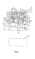
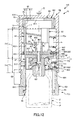
- FIG. 1 is a longitudinal cross-sectional view sequentially illustrating the operation process of the adapter unit (first embodiment) of the present invention.
- FIG. 2 is a longitudinal cross-sectional view sequentially illustrating the operation process of the adapter unit (first embodiment) of the present invention.
- FIG. 3 is a longitudinal cross-sectional view sequentially illustrating the operation process of the adapter unit (first embodiment) of the present invention.
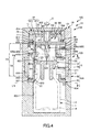
- FIG. 4 is a longitudinal cross-sectional view sequentially showing the operation process of the adapter unit (first embodiment) of the present invention.
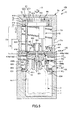
- FIG. 5 is a longitudinal cross-sectional view sequentially illustrating the operation process of the adapter unit (first embodiment) of the present invention.
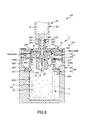
- FIG. 6 is a longitudinal cross-sectional view sequentially illustrating the operation process of the adapter unit (first embodiment) of the present invention.
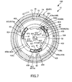
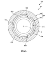
- 7 is a cross-sectional view taken along line AA in FIG. 8 is a cross-sectional view taken along line BB in FIG. 9 is a cross-sectional view taken along the line CC in FIG.
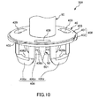
- FIG. 10 is a perspective view of an adapter provided in the adapter unit of the present invention.
- FIG. 11 is a longitudinal sectional view sequentially illustrating the operation process of the adapter unit (second embodiment) of the present invention.
- FIG. 12 is a longitudinal cross-sectional view sequentially illustrating the operation process of the adapter unit (second embodiment) of the present invention.
- FIGS. 1 to 6 are longitudinal sectional views sequentially showing the operation process of the adapter unit (first embodiment) of the present invention
- FIG. 7 is a sectional view taken along the line AA in FIG. 3
- FIG. 4 is a sectional view taken along line BB in FIG. 4
- FIG. 9 is a sectional view taken along line CC in FIG. 4
- FIG. 10 is a perspective view of an adapter provided in the adapter unit of the present invention.
- the lower side in FIGS. 1 to 6 and 10 is “base end” or “down (downward)”, and the upper side is “tip”. Or say "up (upper)”.
- the medical device set 100 includes a medical container 1 and an adapter unit 10 used in a mounted state attached to the medical container 1.
- the medical device set 100 includes a syringe 20 in addition to the medical container 1 and the adapter unit 10 (see FIG. 6).
- a syringe 20 in addition to the medical container 1 and the adapter unit 10 (see FIG. 6).
- the medical container 1 includes a container body 2 and a plug (sealing member) 3.
- the medical container 1 stores a medicine P in powder form, liquid form or the like (in this embodiment, powder form) in advance.
- the medicine P is mixed with a liquid Q such as a dissolving liquid, a diluting liquid, or a chemical liquid supplied from the syringe 20. This mixture is the chemical solution R.
- medicine P it is necessary to dissolve when using a medicine, an antibiotic, a hemostatic agent, or the like that is dangerous if a medical worker accidentally touches it, such as an anticancer agent or an immunosuppressant.
- Drugs drugs that need to be diluted, such as drugs for children, vaccines, heparin, drugs that are used multiple times, such as drugs for children, drugs that easily foam when dissolved in protein preparations or when sucked into syringes, antibody drugs, etc. Examples include drugs with small amounts of stored medicine.
- the liquid Q is not particularly limited, and examples thereof include physiological saline.
- the container body 2 is composed of a bottomed cylindrical member.
- the distal end portion of the container body 2 has an inner diameter and an outer diameter that are reduced in diameter, and constitutes a mouth portion 21 through which liquid passes.
- the base end side structure 6 ⁇ / b> A included in the adapter unit 10 is attached to the mouth portion 21.
- a ring-shaped protrusion 211 is formed on the outer peripheral portion of the mouth portion 21 along the circumferential direction.
- the constituent material of the container body 2 is not particularly limited, and other than glass, for example, polyolefins such as polyethylene and polypropylene, cyclic polyolefins such as cycloolefin polymers and cyclic olefin copolymers, polyesters such as polyethylene terephthalate, vinyl chloride resins, Examples thereof include vinyl resins such as polyvinyl alcohol, polyamides such as nylon 6, nylon 6,6, nylon 6,10, nylon 6,12, etc., and other resin materials such as thermoplastic resins. Species or a combination of two or more can be used. In addition, in order to cut a specific wavelength, a material obtained by adding a light shielding additive to a constituent material may be used.
- polyolefins such as polyethylene and polypropylene
- cyclic polyolefins such as cycloolefin polymers and cyclic olefin copolymers
- polyesters such as polyethylene terephthalate
- the inner surface of the container body 2 may be coated with Teflon (“Teflon” is a registered trademark) or a fluorine coating. Each of these members may have transparency in order to ensure internal visibility.
- a soft plug 3 made of an elastic material is attached to the mouth 21 of the container body 2. Thereby, the mouth part 21 can be liquid-tightly sealed.
- the plug body 3 includes a top plate 31 made of a disc and a cylindrical portion 33 protruding from the base end surface 311 of the top plate 31.
- the top plate 31 is a portion through which a bottle needle (hollow needle) 50 of an adapter (inner structure) 30A as a connector provided in the adapter unit 10 is inserted. Then, the syringe 20 is connected to the adapter 30A pierced through the top plate 31 (see FIG. 6). By operating the syringe 20 in this connected state, the liquid Q from the syringe 20 flows in through the mouth portion 21 or the chemical solution R flows out toward the syringe 20.
- the top plate 31 is particularly sterilized at the distal end surface 312.
- the adapter unit 10 maintains the sterilized state, that is, the aseptic state.
- the outer diameter of the cylindrical portion 33 is set slightly larger than the inner diameter of the mouth portion 21 of the container body 2. Thereby, when the tubular portion 33 is inserted into the mouth portion 21, the tubular portion 33 is in close contact with the inner peripheral surface of the mouth portion 21. Thereby, the mouth part 21 is sealed in a liquid-tight manner.
- Examples of the elastic material constituting the plug body 3 include various rubber materials such as natural rubber, isoprene rubber, butadiene rubber, styrene-butadiene rubber, urethane rubber and fluororubber, and various thermoplastic elastomers such as styrene and polyolefin. 1 type or 2 types or more of these can be mixed and used.
- the syringe 20 is a syringe filled with a liquid Q mixed with the medicine P in advance.
- the syringe 20 has an outer cylinder 201.
- the outer cylinder 201 has a bottomed cylindrical shape, and a mouth part 202 that protrudes in a tubular shape in the distal direction is formed at the bottom.
- the syringe 20 includes a gasket (not shown) that can slide in a liquid-tight manner in the outer cylinder 201, and a plunger (not shown) that is connected to the gasket and moves the gasket in the outer cylinder 201. have. Then, by pressing the plunger, the liquid Q can be discharged from the mouth portion 202 with the gasket.
- a ring-shaped lock member (lock adapter) 203 is disposed concentrically with the mouth portion 202 on the outer peripheral side of the mouth portion 202.
- a female screw 204 that is screwed into the adapter 30 ⁇ / b> A is formed on the inner peripheral portion of the lock member 203. By this screwing, the syringe 20 and the adapter 30A are connected.
- the lock member 203 is integrally formed with the mouth portion 202, but is not limited thereto, and may be configured separately from the mouth portion 202.
- the lock member 203 When the lock member 203 is configured separately from the mouth portion 202, the lock member 203 may be supported so as to be movable along the axial direction of the mouth portion 202, and around the axis of the mouth portion 202. You may be supported so that rotation is possible.
- Such a syringe 20 is connected to the medical container 1 via the adapter 30A.
- the adapter unit 10 includes a cap 7A formed of a cylindrical body, an adapter 30A arranged inside the cap 7A, and a distal end side arranged together with the adapter 30A inside the cap 7A.
- a structure 8A and a proximal-side structure 6A attached to the medical container 1 are provided.
- it does not specifically limit as a constituent material of cap 7A, adapter 30A, the front end side structure 8A, and the base end side structure 6A,
- the material similar to the container main body 2 of the medical container 1 can be used.
- the cap 7A is detachably attached to the base end side structure 6A by screwing, and is rotated around its central axis O when the cap 7A is detached from the base end side structure 6A. It is.
- the cap 7A includes a top plate 75 and a wall portion 76 that is formed in a cylindrical shape along the edge of the top plate 75 and protrudes from the edge toward the proximal direction.
- the wall portion 76 (cylindrical body) of the cap 7A is formed with a cap-side female screw portion (first cap-side screwed portion) 73 on its inner peripheral portion (inner peripheral side). Further, on the wall portion 76 of the cap 7A, a cap-side male screw portion (second cap-side screwing portion) 79 is provided at a position different from the cap-side female screw portion 73, that is, on the outer peripheral portion (outer peripheral side). Is formed.
- the cap-side female screw portion 73 is a portion having a first screw thread (first screw portion) 731 formed in a spiral shape around the central axis O.
- the cap-side male screw portion 79 is a portion having a second screw thread (second screw portion) 791 formed in a spiral shape around the central axis O.
- the pitch s 1 between the first screw threads 731 adjacent to each other along the central axis O direction in the cap-side female screw portion 73 is the central axis in the cap-side male screw portion 79. It is larger than the pitch s 2 between the second screw threads 791 adjacent to each other along the O direction.
- the formation length u 1 along the central axis O direction of the cap-side female screw portion 73 is longer than the formation length u 2 along the central axis O direction of the cap-side male screw portion 79.
- the number of turns of the first screw thread 731 at the cap-side female screw part 73 is equal to or less than the number of turns of the second screw thread 791 at the cap-side male screw part 79.
- a portion on the tip side of the inner peripheral portion of the cap 7A with respect to the cap-side female screw portion 73 is a reduced diameter portion 77 having an inner diameter reduced.
- an inner cylinder 15 made of a cylindrical body is disposed concentrically with the reduced diameter portion 77.
- the inner cylinder 15 is fixed to the reduced diameter portion 77.
- the fixing method is not particularly limited, and for example, a method by fusion (thermal fusion, high frequency fusion, ultrasonic fusion, etc.) or a method by adhesion (adhesion with an adhesive or a solvent) can be used. .
- a projecting portion 151 having a ring shape along the circumferential direction is formed to project from the inner peripheral portion of the inner cylindrical body 15.
- the tip 151 can engage with the protrusion 151.
- the distal-end-side structure 8A is connected to the cap 7A via the inner cylindrical body 15, so that when the cap 7A is removed, it is removed together with the cap 7A (see FIGS. 5 and 6). .
- the adapter 30A is disposed inside the cap 7A so as to be movable toward the proximal direction. As shown in FIG. 1 to FIG. 6 and FIG. 10, the adapter 30A is connected to the main body 40, a bottle needle (hollow needle) 50 through which the stopper 3 of the medical container 1 can be pierced, and a syringe 20. Part 90.
- the main body 40 includes a disk-shaped disk part 403 and a mounting part (adapter-side mounting part) 406 formed to project from the lower surface of the disk part 403.
- the disc portion 403 is formed with a plurality of (three in the illustrated configuration) guide holes 409 that are formed by through holes penetrating in the thickness direction. Yes.
- the guide holes 409 are arranged at equiangular intervals around the central axis O, respectively.
- the distal end side guide portions 82 included in the distal end side structure 8A and the proximal end side guide portions 67 included in the proximal end side structure 6A are collectively inserted.
- the adapter 30A moves in the proximal direction
- the distal end side guide portions 82 and the proximal end side guide portions 67 can collectively guide the adapter 30A (see FIGS. 4 and 5). .
- Each guide hole 409 may be open toward the outer peripheral side of the disc portion 403.
- the mounting portion 406 has a plurality of (three in the configuration shown in FIG. 10) projecting pieces 406a projecting from the lower surface of the disc portion 403, and is fitted into the mouth portion 21 of the container body 2 from the outside thereof. It will be attached to the part 21.
- a claw 406b protrudes from the inside of each protruding piece 406a. As shown in FIGS. 5 and 6, each claw 406 b is engaged with the protrusion 211 of the mouth portion 21 when the mounting portion 406 is fitted into the mouth portion 21 of the container body 2. As a result, the adapter 30A can be reliably prevented from unintentionally leaving the container body 2.
- each protrusion piece 406a expands in the radial direction. Thereby, the mounting portion 406 is easily mounted on the mouth portion 21.
- An adapter-side male screw portion (adapter-side screwing portion) 408 is provided on the outer peripheral portion of the disc portion 403.
- the adapter-side male screw portion 408 is a portion that is screwed with the cap-side female screw portion 73 of the cap 7A.
- the adapter-side male screw portion 408 includes a protrusion 401 formed in a ring shape along the circumferential direction on the outer peripheral portion (edge portion) of the disc portion 403, and the protrusion 401
- This is a portion in which a plurality of (three in this embodiment) grooves 402 are formed in the middle of the forming direction. Each groove 402 is formed to be inclined with respect to the central axis O.
- the first screw thread 731 of the cap-side female screw portion 73 of the cap 7A can be inserted into each groove 402, that is, inserted into the groove 402.
- the adapter-side male screw portion 408 and the cap-side female screw portion 73 are screwed together.
- the bottle needle 50 is disposed on the central axis O on the base end surface of the disc portion 403.
- the bottle needle 50 has a sharp needle tip 501 that can pierce the top plate 31 of the stopper 3 of the medical container 1.
- the bottle needle 50 is a hollow needle and has at least one (two in this embodiment) side hole 502 opened on a side surface thereof (see FIG. 4).
- connection part 90 is a part to which the syringe 20 is connected in a state where the cap 7A is detached (see FIG. 6).
- the connecting portion 90 has a cylindrical shape and is disposed on the central axis O at the distal end surface of the disc portion 403. This connecting portion 90 communicates with the bottle needle 50.
- the inner peripheral part 901 of the connecting part 90 has a tapered shape whose inner diameter gradually decreases in the proximal direction. And when the syringe 20 is connected to the connection part 90, the outer peripheral part 205 of the opening part 202 of the syringe 20 and the inner peripheral part 901 of the connection part 90 fit. In this state, the syringe 20 and the medical container 1 (container body 2) communicate with each other via the connection unit 90 and the bottle needle 50, and the liquid can flow back and forth between them.
- a male screw 902 is formed on the outer periphery of the connecting portion 90.
- the female screw 204 of the lock member 203 of the syringe 20 can be screwed into the male screw 902. By this screwing, the state where the syringe 20 is connected to the connecting portion 90 can be maintained.
- the front end side structural body 8A is disposed inside the cap 7A (inner cylinder 15) so as to be rotatable around the central axis O.
- the distal-end-side structure 8A includes a main body 81 and a plurality of (three in this embodiment) formed to protrude from the main body 81 toward the base end. Book) guide part (front end side guide part) 82.
- the main body 81 includes a top plate 811 and a wall portion 812 that is formed in a cylindrical shape along the edge of the top plate 811 and protrudes from the edge toward the proximal direction.
- the main body 81 is located in the inner cylinder 15.
- a through hole 813 that penetrates in the thickness direction is formed at the center of the top plate 811.
- a through hole 152 is also formed in the inner cylinder 15 at a position where the through hole 813 faces. Then, in a state where the cap 7A has not yet been detached (unused state), the distal end portion of the connection portion 90 of the adapter 30A is inserted into at least the through hole 813 of the through holes 813 and 152 (see FIG. 3). ).
- the total length of the adapter unit 10 can be shortened only by the inserted portion, which contributes to the miniaturization of the adapter unit 10.
- a plurality of protrusions 814 are formed on the outer peripheral portion of the wall portion 812 so as to form a ring shape along the circumferential direction. These protrusions 814 are spaced apart from each other along the central axis O, and the protrusions 814 located on the most proximal side can engage with the protrusions 151 of the inner cylinder 15. By this engagement, it is possible to reliably prevent the distal end side structural body 8A from being detached from the inner cylindrical body 15. Further, by this engagement, the distal-end-side structure 8A is disposed so as to be rotatable around the central axis O inside the cap 7A (inner cylinder 15).
- a plurality of long flat plate-like distal end side guide portions 82 extend along the central axis O direction.
- Each distal end side guide portion 82 is inserted into the guide hole 409 of the adapter 30A.
- each distal side guide portion 82 is engaged with a surface on the opposite side of the direction of screwing when the cap 7A is attached to the proximal end structure 6A.
- a portion 823 is formed.
- the engaging portion 823 is, when the mounting of the cap 7A to the base end side structure 6A is completed, that is, at the screwing limit between the cap 7A and the base end side structure 6A. It engages with an engaging portion 672 formed in the proximal end side guide portion 67 of the proximal end side structure 6A.
- a protrusion 823a is formed on the engaging portion 823 of each distal end side guide portion 82, and when the mounting of the cap 7A to the proximal end structure 6A is completed, that is, the cap 7A and the proximal end side At the limit of screwing with the structure 6A, it engages with a protrusion 672a formed on the engagement portion 672 of the base end side guide portion 67 of the base end side structure 6A (see FIGS. 4 and 8).
- the proximal-side structure 6A is attached to the housing member 65 (housing portion) 65 having a bottomed cylindrical shape capable of housing the entire medical container 1 and the housing member 65. And a guide structure 63.
- the storage member 65 can store the medical container 1 inside thereof. Thereby, even when the medicine P is a dangerous medicine if a medical worker touches it by mistake, even if the medicine P adheres to the outer surface of the container body 2 during the manufacture of the medical container 1, for example, the storage member 65 Since the container main body 2 is covered, it is possible to prevent the surrounding contamination and to ensure the safety of the medical staff. Further, the medical container 1 can be gripped through the storage member 65 in the same manner as a conventional vial container.
- a proximal end side female screw portion (base end side screwing portion) 651 that is screwed with the cap side male screw portion 79 of the cap 7A is formed on the inner peripheral portion of the distal end of the storage member 65.
- the proximal-side female screw portion 651 has a groove (screw groove) 655 formed in a spiral shape around the central axis O. Then, the second screw thread 791 of the cap-side male screw portion 79 of the cap 7A can be inserted into the groove 655, that is, inserted. Thereby, the base end side female screw part 651 and the cap side male screw part 79 are screwed together.
- the formation length along the central axis O direction of the base end side female screw portion 651 is the same as the formation length u 2 of the cap side male screw portion 79.
- cap-side male threaded portion 79 and the proximal-end-side female threaded portion 651 are screwed together, so that the cap 7A is attached to the storage member 65, so that the top plate 31 of the plug 3 is sterilized. This is maintained until the medical device set 100 is used.
- a detachment preventing portion 652 configured by a ring-shaped protrusion along the circumferential direction is provided at a portion closer to the base end side than the base end side female screw portion 651. Protrusions are formed.
- the detachment preventing portion 652 is a portion that engages with the guide structure 63 and prevents unintentional detachment of the guide structure 63 from the storage member 65.
- a plurality of (for example, three) ribs 653 extending along the central axis O direction protrude from the inner peripheral portion of the distal end of the storage member 65 at a portion closer to the proximal end than the separation preventing portion 652.
- the ribs 653 are arranged at equiangular intervals around the central axis O, respectively.
- each rib 653 contacts the outer peripheral part of the container main body 2 of the medical container 1, respectively, and prevents the positional deviation of the radial direction with respect to the proximal end structure 6A (housing member 65) of the said medical container 1 concerned. can do.
- Each rib 653 also functions as a restricting portion that restricts rotation of the medical container 1 around the central axis O with respect to the storage member 65. Accordingly, when connecting the syringe 20 to the adapter 30A in communication with the medical container 1, the storage member 65 is gripped, and the male screw 902 of the connection portion 90 of the adapter 30A and the female screw of the lock member 203 of the syringe 20 There is an advantage that 204 can be screwed together.
- the guide structure 63 includes a ring-shaped main body portion 631, three long plate-shaped guide portions (base end side guide portions) 67 protruding from the main body portion 631, and each base end side guide portion 67.
- Leg portions (ribs) 634 which are portions extending in the proximal direction.
- Each base end side guide portion 67 extends along the direction of the central axis O, and is inserted into the guide hole 409 of the adapter 30A moving in the base end direction (see FIG. 5). . Thereby, the adapter 30A is guided together with the distal end side guide portion 82 of the distal end side structure 8A, and the adapter 30A is restricted from rotating together with the cap 7A. Further, the base end side guide portions 67 are arranged at equiangular intervals around the central axis O, respectively. Thereby, adapter 30A can be guided stably.
- each base end side guide portion 67 has an engaging portion 672 on the surface in the direction of screwing when the cap 7A is attached to the base end side structure 6A. Is formed.
- the engaging portion 672 is provided when the attachment of the cap 7A to the base end side structure 6A is completed, that is, at the screwing limit between the cap 7A and the base end side structure 6A. It engages with an engaging portion 823 formed in the distal end side guide portion 82 of the distal end side structure 8A.
- a protrusion 672a is formed on the engaging portion 672 of each base end side guide portion 67, and when the attachment of the cap 7A to the base end side structure 6A is completed, that is, the cap 7A and the base end At the limit of screwing with the side structure 6A, it engages with the protrusion 823a formed on the engagement portion 823 of the distal end side guide portion 82 of the distal end side structure 8A (see FIGS. 4 and 8).
- the legs 634 are arranged at equiangular intervals around the central axis O, respectively.
- the ribs 653 of the storage member 65 are inserted between the leg portions 634. This reliably prevents the guide structure 63 (base end side guide portion 67) from rotating around the central axis O with respect to the storage member 65. By restricting the rotation in this manner, the guide structure 63 rotates together with the cap 7A with respect to the storage member 65 when the storage member 65 and the cap 7A are held and the cap 7A is detached. Is prevented. That is, each rib 653 and each leg 634 functions as a restricting portion that restricts the rotation of the guide structure 63 around the central axis O relative to the storage member 65.
- an engaging portion (mounting portion) 633 that engages (attaches) to the shoulder portion 22 of the container main body 2 is formed on the inner peripheral portion of the main body portion 631. Thereby, detachment
- the adapter unit 10 is attached to the unused medical container 1 in which the medicine P has been stored in advance, that is, the assembly operation for setting the attached state is shown in FIGS. 1 to 4, 7, and 8. This will be described with reference to FIG. In this assembling operation, a first operation and a second operation are performed.
- proximal-side structure 6A is mounted on the medical container 1 in advance and assembled before performing the first operation and the second operation. This assembly is performed as follows.
- the base end side structure 6A is set in a state where the storage member 65 and the guide structure 63 are separated. Then, the medical container 1 is inserted into the storage member 65, and the guide structure 63 is inserted from above.
- the separation preventing portion 652 of the storage member 65 engages with the guide structure 63 (main body portion 631), and the guide structure 63 is inserted into the storage member 65. It will be attached. Accordingly, the medical container 1 is prevented from being detached from the storage member 65 together with the guide structure 63, and the proximal end structure 6A is attached.
- a medical container assembly 103 an assembly in which the proximal-side structure 6A is attached to the medical container 1 is referred to as a medical container assembly 103.
- an adapter assembly 101 is formed by assembling the adapter 30A and the distal-end-side structure 8A. This assembly is performed as follows.
- Each guide part 82 of the tip side structure 8A is inserted into each guide hole 409 of the adapter 30A. This insertion is performed until the main body portion 81 of the distal end side structural body 8A comes into contact with the main body portion 40 of the adapter 30A. By such an assembling operation, the adapter assembly 101 is obtained.
- a cap assembly (first assembly) 102 in which a cap 7A and an adapter assembly 101 are assembled is used. This assembly is performed as follows.
- the adapter assembly 101 is inserted into the cap 7A from its proximal end side, and the cap-side female screw portion 73 of the cap 7A and the adapter-side male screw portion 408 of the adapter 30A are screwed together. This screwing is performed up to the screwing limit between the cap-side female screw portion 73 and the adapter-side male screw portion 408.
- the protrusion 814 located on the most proximal side of the distal end side structure 8A of the adapter assembly 101 is engaged with the protrusion 151 of the inner cylinder 15 in the cap 7A. Match. Thereby, it is possible to reliably prevent the adapter assembly 101 from being unintentionally detached from the cap 7A.
- the cap assembly 102 in which the adapter assembly 101 is housed in the cap 7A and assembled is obtained.
- cap assembly 102 and the medical container assembly 103 are assembled. This assembly is performed as follows.
- the cap 7 ⁇ / b> A of the cap assembly 102 is inserted into the proximal side structure 6 ⁇ / b> A of the medical container assembly 103, and the cap assembly 102 is attached to the medical container assembly 103 around the central axis O. Rotate in a predetermined direction. Thereby, the cap side male screw part 79 of the cap 7A and the base end side female screw part 651 of the base end side structure 6A are screwed together. This screwing is performed up to the screwing limit between the cap-side male screw portion 79 and the base-end side female screw portion 651 (see FIG. 4).
- the distal-end-side structure 8A of the cap assembly 102 is in the medical container assembly. While rotating with respect to the guide structure 63 (base end side structure 6A) of the three-dimensional body 103, the guide structure 63 gradually approaches. At that time, as shown in FIG. 7, the distal end side guide portion 82 of the distal end side structure 8A and the proximal end guide portion 67 of the guide structure 63 collide with each other. This collision is repeated at least once, depending on the pitch s 2 , the formation length u 2 , and the number of windings of the cap-side male screw portion 79.
- the distal end side guide portion 82 and the proximal end side guide portion 67 screw the cap side male screw portion 79 and the proximal end side female screw portion 651 into the collision surface when they collide with each other.
- An inclined surface 824 and an inclined surface 673 that are inclined in the same direction in the radial direction with respect to the central axis O are formed in the rotational direction (the direction in which the screwing proceeds).
- the inclined surface 824 faces the collision surface when the distal end side guide portion 82 collides with the proximal end side guide portion 67, that is, the surface in the direction of threading, and faces the direction of threading.
- the inclined surface 673 is a collision surface when the proximal end side guide portion 67 collides with the distal end side guide portion 82, that is, a surface on the opposite side to the traveling direction of the screwing, toward the traveling direction of the screwing. It is formed as an inclined surface inclined outward in the radial direction with respect to the central axis O.
- the distal end side guide portion 82 has the inclined surface 824 on the inclined surface 673 of the proximal end side guide portion 67 of the proximal end side guide portion 67.
- the distal end side guide portion 82 is elastically deformed outward in the radial direction with respect to the central axis O (in the direction of arrow D in FIG. 7), and reliably climbs over the proximal end side guide portion 67 from the outside. be able to.
- the distal end side guide portion 82 that has overcome the proximal end side guide portion 67 is restored to its original shape.
- the engagement between the engagement portion 823 of the distal end side guide portion 82 and the proximal end side guide portion 67 is limited at the screwing limit between the cap side male screw portion 79 and the proximal end side female screw portion 651.
- the mating portion 672 is engaged. This restricts the distal-side guide portion 82 from rotating together with the cap 7A in the direction in which the cap-side male screw portion 79 and the base end-side female screw portion 651 are unscrewed (retracting direction of the screwing). .
- at least a part of the engaged guide portion 82 and the guide portion 67 are adjacent to each other in the circumferential direction.
- the cap assembly 102 and the medical container assembly 103 are assembled, and as a result, the mounted medical container 1 with the adapter unit 10 mounted thereon is obtained.
- the adapter unit 10 can be easily and securely attached to the medical container 1 by a simple operation of screwing the cap 7A of the cap assembly 102 and the proximal end structure 6A of the medical container assembly 103 together. can do. Further, this mounting state is reliably maintained by screwing between the cap 7A and the base end structure 6A, and the cap 7A is unintentional even if a tensile force in the distal direction acts on the cap 7A, for example. It is prevented from leaving.
- the cap 7A is gradually released from being screwed with the base-end-side female screw portion 651 of the base-end-side structure 6A of the cap-side male screw portion 79, Move toward the tip.
- the pitch s 1 of the cap side female screw portion 73 is set larger than the pitch s 2 of the cap side male screw portion 79.
- the total moving distance of the adapter 30A is “((length of one pitch of the cap-side female screw portion 73) ⁇ (length of one pitch of the cap-side male screw portion 79)) ⁇ (cap-side female screw portion 73. No. of turns) ”.
- the protrusion 823a of the distal end side guide portion 82 and the protrusion 672a of the proximal end side guide portion 67 are engaged as described above, and therefore the distal end side guide portion 82 is engaged.
- the proximal end guide portion 67 adjacent to each other in the circumferential direction are maintained, and the adapter 30A can move smoothly in the proximal direction.
- the cap 7A is detached from the base end structure 6A together with the tip end structure 8A.
- the adapter 30A has moved the total moving distance, the adapter-side male threaded portion 408 is detached from the cap-side female threaded portion 73, and the bottle needle 50 penetrates the plug body 3 of the medical container 1.
- the inside of the medical container 1 communicates with the outside through the bottle needle 50.
- the adapter 30A is attached by being engaged with the medical container 1 by the attachment portion 406. Thereby, the piercing state to the stopper 3 of the bottle needle 50 is maintained.
- the syringe 20 is connected to the adapter 30 ⁇ / b> A in communication with the medical container 1 (hereinafter, this state is referred to as “connected state”). Thereby, the medical container 1 and the syringe 20 communicate with each other through the adapter 30A.
- connection operation is performed by screwing the male screw 902 of the connecting portion 90 of the adapter 30A and the female screw 204 of the lock member 203 of the syringe 20 together.
- the plunger of the syringe 20 is pressed in the connected state to supply the liquid Q from the syringe 20 into the medical container 1.
- the liquid Q flows down the connecting portion 90 and the bottle needle 50 in this order, and flows into the medical container 1 through the side hole 502 of the bottle needle 50.
- medical agent P mix, and the chemical
- the drug P is completely dissolved in the liquid Q, and the drug solution R is reliably generated.
- the adapter unit 10 configured as described above is configured such that the adapter 30A is securely attached to the medical container 1 in conjunction with the operation of removing the cap 7A, that is, removing the cap 7A.
- the medical container 1 can be used reliably after the cap 7A is detached.
- the adapter has an adapter and a cap that are screwed together, and a base end side structure, and is engaged (snapped) between a protrusion provided on the base end structure and a recess provided on the cap.
- the cap and the base end side structure are connected by fitting
- a tensile force is applied to the cap unintentionally during the rotation of the cap (for example, an operator)
- the adapter will detach from the proximal structure with the cap before it is fully attached to the medical container.
- a syringe cannot be connected to the medical container, and the medical container cannot be used.
- the adapter unit 10 can use the medical container 1 quickly and reliably after removing the cap 7A, and has excellent operability.
- FIG. 11 and FIG. 12 are longitudinal sectional views sequentially showing the operation process of the adapter unit (second embodiment) of the present invention.
- the wall portion 76 (cylindrical body) of the cap 7 ⁇ / b> B is located at a position different from the cap-side female screw portion 73, i.e., more than the cap-side female screw portion 73.
- a cap-side female screw portion (second cap-side screwed portion) 74 is formed on the end side.
- the cap-side female screw portion 74 is a portion having a second screw thread (second screw portion) 741 formed in a spiral shape around the central axis O.
- the pitch s 1 between the first screw threads 731 adjacent to each other along the central axis O direction in the cap-side female screw portion 73 is the central axis in the cap-side female screw portion 74. It is larger than the pitch s 2 between the second screw threads 741 adjacent to each other along the O direction. Further, the formation length u 1 along the direction of the central axis O of the cap side female screw portion 73 is longer than the formation length u 2 along the direction of the central axis O of the cap side female screw portion 74.
- the second cap side is provided on the opposite side of the inner peripheral portion of the wall portion 76, that is, on the outer peripheral portion.
- the outer diameter of the cap 7B can be made smaller than when a cap-side male screw portion is provided as the screwing portion.
- a projecting portion 771 having a ring shape along the circumferential direction is formed to protrude from the reduced diameter portion 77 of the cap 7B.
- the protrusion 771 can be engaged with a protrusion 814 that is located on the most proximal side of the distal-side structure 8A.
- the distal-end-side structure 8A is connected to the cap 7B, and therefore, when the cap 7B is removed, it is removed together with the cap 7B (see FIG. 12).
- the adapter 30B has the mounting portion 406 omitted from the disc portion 403.
- a plurality (three in this embodiment) of engagement holes 405 are formed in the disc portion 403 at positions different from the three guide holes 409 in the circumferential direction.
- Each engagement hole 405 has a base end side structure when the adapter 30B moves toward the base end, and at the limit of movement, that is, when the bottle needle 50 penetrates the plug 3 of the medical container 1. This is the part with which the body 6B engages. By this engagement, it is possible to reliably prevent the bottle needle 50 of the adapter 30B from being removed from the plug body 3.
- the proximal-side structure 6 ⁇ / b> B includes a cylindrical base portion 61 and a disc portion (base-end disc portion) 62 disposed on the distal end side of the base portion 61.
- Three guide portions (base end side guide portions) 67 are arranged between the base portion 61 and the disc portion 62, and the base portion 61 and the disc portion are interposed through the respective guide portions 67. 62 is connected.
- each guide portion 67 is not inserted into the guide hole 409.
- the base 61 is arranged concentrically with the container main body 2 on the outer peripheral side of the container main body 2 in a mounted state mounted on the medical container 1.
- the adapter unit 10 When the adapter unit 10 is operated, that is, when the cap 7B is rotated around the central axis O, the cap 7B is gripped by one hand and the base 61 is gripped by the other hand to perform the operation. be able to.
- the base 61 functions as a gripping part that is gripped when the adapter unit 10 is operated.
- a base end side male screw portion (base end side screwing portion) 69 is provided on the outer peripheral end portion of the base portion 61.
- the base end side male screw portion 69 has a groove (thread groove) 691 formed in a spiral shape around the central axis O. Then, the second screw thread 741 of the cap-side female screw portion 74 of the cap 7B can be inserted into the groove 691, that is, inserted. Thereby, the base end side male screw portion 69 and the cap side female screw portion 74 are screwed together.
- the formation length along the central axis O direction of the base end side male screw portion 69 is the same as the formation length u 2 of the cap side female screw portion 74.
- a plurality of (for example, three) ribs 611 extending along the central axis O direction are formed to protrude from the inner peripheral portion of the base portion 61.
- Each rib 611 can contact the outer peripheral portion of the container body 2 of the medical container 1 to prevent rattling, that is, radial displacement of the medical container 1 with respect to the proximal end structure 6B.
- the disc part 62 has a disc shape, and its surface is orthogonal to the central axis O and is concentrically arranged with the base part 61.
- the diameter of the disc part 62 is smaller than the diameter of the base part 61.
- a plurality of sharp (for example, four) protrusions 621 are formed on the base end face of the disc portion 62 so as to protrude. Each protrusion 621 is punctured on the distal end surface 312 of the plug 3 of the medical container 1. Thereby, positioning of the base end side structure 6B (base end side guide part 67) and the medical container 1 is made.
- the base end side structure 6B includes a mounting portion 66 that is mounted on the medical container 1, and an engaging portion 68 that engages with the adapter 30B that is at the movement limit.
- the mounting portion 66 includes three projecting pieces 661 that project from the base end surface of the disc portion 62 toward the base end direction.
- the protrusions 661 are arranged at equiangular intervals around the central axis O, respectively. Further, the protruding pieces 661 and the proximal end side guide portions 67 are alternately arranged around the central axis O.
- Each projection piece 661 is formed with a claw 662 protruding inwardly at the lower end thereof. And as shown in FIG. 12, each nail
- the engaging portion 68 is composed of three protruding pieces 681 protruding from the distal end surface of the disc portion 62 toward the distal end direction.
- the protrusions 681 are arranged at equiangular intervals around the central axis O, respectively.
- each protrusion 681 is formed with a claw 682 protruding outward at the upper end thereof.
- the respective claws 682 are respectively connected to the main body 40 of the adapter 30B. Engage with the edge of the mating hole 405. Thereby, the base end side structure 6B and the adapter 30B are connected, and the adapter 30B is prevented from being unintentionally detached from the base end side structure 6B.
- the seal member 16 is interposed between the inner peripheral portion of the base portion 61 of the base end side structure 6B and the outer peripheral portion of the container body 2 of the medical container 1.
- the seal member 16 has a ring shape along the inner peripheral portion of the base portion 61 and is fixed to the inner peripheral portion of the base portion 61.
- the fixing method is not particularly limited, and for example, a method using adhesion (adhesion with an adhesive or a solvent), a method using fusion (thermal fusion, high frequency fusion, ultrasonic fusion, etc.), or the like can be used. .
- Such a sealing member 16 maintains the sterilized state of the top plate 31 of the plug 3. This state is reliably maintained until the medical device set 100 is used. Therefore, in the medical device set 100, the seal member 16 functions as a means for maintaining the sterilized state of the top plate 31 of the plug 3 while the adapter unit 10 is mounted on the medical container 1.
- the sealing member 16 does not specifically limit as a constituent material of the sealing member 16,
- the material similar to the plug 3 of the medical container 1 can be used.
- the adapter unit 10 can be easily and reliably attached to the medical container 1 as in the first embodiment. As shown in FIG. 12, the adapter 30 ⁇ / b> B is attached to the medical container 1 when the cap 7 ⁇ / b> B is removed. And if the syringe 20 is connected to the adapter 30B after that, the medical container 1 can be used reliably.
- the proximal-side structure 6B is attached to the unused medical container 1 in which the medicine P is stored in advance by attaching the adapter unit 10 and assembling, prior to the first operation.
- the medical container assembly 102 may be preliminarily mounted on the medical container 1, but is not limited thereto.
- the medical container assembly 102 is not used, and the proximal-end structure 6 ⁇ / b> B and the second structural body 6 ⁇ / b> B are connected by the third operation. After assembling the assembly, the assembly can be attached to the medical container 1.
- each part which comprises an adapter unit is a thing of arbitrary structures which can exhibit the same function. Can be substituted. Moreover, arbitrary components may be added.
- the adapter unit of the present invention may be a combination of any two or more configurations (features) of the above embodiments.
- the number of the distal end side guide portions and the proximal end side guide portions that guide the adapter is three in each of the above embodiments, but is not limited thereto. For example, one, two, or four It may be the above.
- the proximal end side guide portion when the distal end side guide portion collides with the proximal end side guide portion and the distal end side guide portion gets over the proximal end side guide portion, the proximal end side guide portion is elastically deformed inward in the radial direction with respect to the central axis O.
- the distal end side guide portion and the proximal end side guide portion may be elastically deformed in directions opposite to each other in the radial direction with respect to the central axis O.
- the distal end side guide portion and the proximal end side guide portion are restored to the original shape.
- the inclined surface of the distal end side guide portion and the inclined surface of the proximal end side guide portion may be inclined surfaces that are inclined inward in the radial direction with respect to the central axis O in the screwing direction. At this time, the distal end side guide portion gets over the proximal end side guide portion from the inside thereof.
- the first assembly including the adapter and the tip side structure is first assembled with the adapter and the tip side structure.
- the present invention is not limited to this.
- the tip side structure is rotatably accommodated in the cap, and the tip side structure, the cap, and the tip side structure are assembled, and the cap and the tip side are assembled.
- An operation of obtaining a first assembly having a structure may be used.
- the subsequent operation is an operation of assembling the assembly having the cap and the tip side structure and the adapter to obtain the first assembly having the cap, the adapter and the tip side structure. And this operation is performed by screwing an adapter to a cap to a screwing limit, inserting a front end side guide part in the guide hole of an adapter.
- the adapter unit according to the present invention has a cylindrical shape, and is an adapter used in a mounted state mounted on a medical container including a container main body having a mouth portion at a distal end portion thereof and a soft sealing member for sealing the mouth portion.
- a first cap-side threaded portion having a first threaded portion formed in a cylindrical shape around the central axis on the inner circumferential side of the cylindrical body,
- a cap having a second cap-side threaded portion having a second threaded portion spirally formed around the central axis at a position different from the first cap-side threaded portion of the cylindrical body;
- a main body having a disk portion in which a guide hole penetrating in the thickness direction is formed, and a disk portion of the disk portion.
- An adapter having a screw-side screwing portion, a hollow needle capable of penetrating the sealing member, and arranged inside the cap so as to be rotatable around the central axis, inserted into the guide hole, When the adapter moves toward the proximal direction in the mounted state, the adapter is guided along the moving direction, and the adapter is restricted from rotating with the cap, along the central axis direction.
- a distal-end-side structure having at least one elongated distal-end-side guide portion that extends, a mounting portion that is attached to the container body, and a proximal end side that is screwed to the second cap-side screwing portion
- the distal end guide portion engages with the distal end guide portion in the mounted state in the threaded portion, and the distal end guide portion extends in the retracting direction of the second cap side threaded portion and the proximal end threaded portion.
- a proximal-side structure having at least one elongated proximal-side guide portion extending along the central axis direction, the pitch at the first screw portion being the first
- the distal end side guide portion is inserted into the guide hole, and the first cap side screw portion and the adapter side screw portion are Assembling the cap, the adapter, and the tip side structure so that the screw is screwed to the screwing limit, and a first assembly having the cap, the adapter, and the tip side structure.
- a second operation of assembling, and during the second operation, the distal side guide portion and the base The end guides collide with each other at least once, and one or both of them elastically deform in the radial direction with respect to the central axis, so that the distal end guide passes over the proximal end guide portion, and the second cap side screwing
- the adapter By releasing the screwing of the second cap side screwing portion and the base end side screwing portion, when the cap is detached from the base end side structure together with the distal end side structure, The adapter moves toward the proximal end while preventing rotation by inserting the distal end guide portion engaged with the proximal end guide portion into the guide hole. From the first cap side screwing portion, the screwing portion is Disengaging with the hollow needle pierces the sealing member, in the container body through the hollow needle is communicated with the outside. Therefore, it can be easily and reliably attached to the medical container, and the medical container can be used reliably after the cap is removed in the attached state. Therefore, the adapter unit of the present invention has industrial applicability.
Landscapes
- Health & Medical Sciences (AREA)
- Pharmacology & Pharmacy (AREA)
- Life Sciences & Earth Sciences (AREA)
- Animal Behavior & Ethology (AREA)
- General Health & Medical Sciences (AREA)
- Public Health (AREA)
- Veterinary Medicine (AREA)
- Medical Preparation Storing Or Oral Administration Devices (AREA)
- Infusion, Injection, And Reservoir Apparatuses (AREA)
Abstract
L'invention concerne une unité adaptateur (10) qui est utilisée dans un état monté sur un contenant médical (1) et qui comporte un capuchon (7A), un adaptateur (30A), une structure côté extrémité distale (8A) ayant une partie de guidage côté extrémité distale (82) pour guider l'adaptateur (30A), et une structure côté extrémité proximale (6A) ayant une partie de guidage côté extrémité proximale (67) pour guider l'adaptateur (30A). Lorsqu'un état monté doit être obtenu, le capuchon (7A), l'adaptateur (30A) et la structure côté extrémité distale (8A) sont assemblés pour former un ensemble capuchon (102), et l'ensemble capuchon (102) et la structure côté extrémité proximale (6A) sont ensuite assemblés. Pendant cette opération, la partie de guidage côté extrémité distale (82) et la partie de guidage côté extrémité proximale (67) entrent en collision au moins une fois, et une ou les deux sont élastiquement déformées, ce par quoi l'une chevauche l'autre et les deux sont par la suite engagées l'une avec l'autre.
Priority Applications (1)
| Application Number | Priority Date | Filing Date | Title |
|---|---|---|---|
| JP2013554210A JP6096678B2 (ja) | 2012-01-19 | 2012-12-12 | アダプタユニット |
Applications Claiming Priority (2)
| Application Number | Priority Date | Filing Date | Title |
|---|---|---|---|
| JP2012008917 | 2012-01-19 | ||
| JP2012-008917 | 2012-01-19 |
Publications (1)
| Publication Number | Publication Date |
|---|---|
| WO2013108521A1 true WO2013108521A1 (fr) | 2013-07-25 |
Family
ID=48798958
Family Applications (1)
| Application Number | Title | Priority Date | Filing Date |
|---|---|---|---|
| PCT/JP2012/082212 WO2013108521A1 (fr) | 2012-01-19 | 2012-12-12 | Unité adaptateur |
Country Status (2)
| Country | Link |
|---|---|
| JP (1) | JP6096678B2 (fr) |
| WO (1) | WO2013108521A1 (fr) |
Cited By (4)
| Publication number | Priority date | Publication date | Assignee | Title |
|---|---|---|---|---|
| CN107362036A (zh) * | 2017-07-31 | 2017-11-21 | 欧罗巴科技发展(深圳)有限公司 | 一种安全性高的药瓶适配器 |
| JP2021521961A (ja) * | 2018-04-23 | 2021-08-30 | ホスピーラ インコーポレイテッド | 薬剤バイアルのためのアクセスおよび蒸気格納システム、およびそれを作製および使用する方法 |
| WO2022125763A1 (fr) * | 2020-12-10 | 2022-06-16 | Elanco Us Inc. | Dispositif d'enveloppe |
| USD1010112S1 (en) | 2021-07-03 | 2024-01-02 | KAIRISH INNOTECH Private Ltd. | Vial adapter with valve |
Citations (5)
| Publication number | Priority date | Publication date | Assignee | Title |
|---|---|---|---|---|
| JP2001161792A (ja) * | 1999-10-20 | 2001-06-19 | Becton Dickinson & Co | 瓶および医療容器用の移送セット |
| JP2001508680A (ja) * | 1997-01-24 | 2001-07-03 | スミスクライン・ビーチャム・バイオロジカルス(ソシエテ・アノニム) | 新規デバイス |
| JP2005525971A (ja) * | 2002-02-20 | 2005-09-02 | ビオドム | 容器とコンテナとの間を接続するためのデバイスおよびこのデバイスを備えるすぐに使用可能なアセンブリ |
| WO2007068825A1 (fr) * | 2005-12-14 | 2007-06-21 | Biocorp Recherche Et Developpement | Dispositif de connexion a fonctionnement securise entre deux recipients |
| JP2011224223A (ja) * | 2010-04-21 | 2011-11-10 | Terumo Corp | 医療用具接続具および薬剤投与具 |
-
2012
- 2012-12-12 WO PCT/JP2012/082212 patent/WO2013108521A1/fr active Application Filing
- 2012-12-12 JP JP2013554210A patent/JP6096678B2/ja active Active
Patent Citations (5)
| Publication number | Priority date | Publication date | Assignee | Title |
|---|---|---|---|---|
| JP2001508680A (ja) * | 1997-01-24 | 2001-07-03 | スミスクライン・ビーチャム・バイオロジカルス(ソシエテ・アノニム) | 新規デバイス |
| JP2001161792A (ja) * | 1999-10-20 | 2001-06-19 | Becton Dickinson & Co | 瓶および医療容器用の移送セット |
| JP2005525971A (ja) * | 2002-02-20 | 2005-09-02 | ビオドム | 容器とコンテナとの間を接続するためのデバイスおよびこのデバイスを備えるすぐに使用可能なアセンブリ |
| WO2007068825A1 (fr) * | 2005-12-14 | 2007-06-21 | Biocorp Recherche Et Developpement | Dispositif de connexion a fonctionnement securise entre deux recipients |
| JP2011224223A (ja) * | 2010-04-21 | 2011-11-10 | Terumo Corp | 医療用具接続具および薬剤投与具 |
Cited By (6)
| Publication number | Priority date | Publication date | Assignee | Title |
|---|---|---|---|---|
| CN107362036A (zh) * | 2017-07-31 | 2017-11-21 | 欧罗巴科技发展(深圳)有限公司 | 一种安全性高的药瓶适配器 |
| JP2021521961A (ja) * | 2018-04-23 | 2021-08-30 | ホスピーラ インコーポレイテッド | 薬剤バイアルのためのアクセスおよび蒸気格納システム、およびそれを作製および使用する方法 |
| US11224555B2 (en) | 2018-04-23 | 2022-01-18 | Hospira, Inc. | Access and vapor containment system for a drug vial and method of making and using same |
| JP7186798B2 (ja) | 2018-04-23 | 2022-12-09 | ホスピーラ インコーポレイテッド | 薬剤バイアルのためのアクセスおよび蒸気格納システム、およびそれを作製および使用する方法 |
| WO2022125763A1 (fr) * | 2020-12-10 | 2022-06-16 | Elanco Us Inc. | Dispositif d'enveloppe |
| USD1010112S1 (en) | 2021-07-03 | 2024-01-02 | KAIRISH INNOTECH Private Ltd. | Vial adapter with valve |
Also Published As
| Publication number | Publication date |
|---|---|
| JP6096678B2 (ja) | 2017-03-15 |
| JPWO2013108521A1 (ja) | 2015-05-11 |
Similar Documents
| Publication | Publication Date | Title |
|---|---|---|
| JP5875974B2 (ja) | コネクタおよびコネクタ組立体 | |
| JP5888606B2 (ja) | 薬剤調製器具 | |
| WO2012002315A1 (fr) | Connecteur et ensemble connecteur | |
| JP5361875B2 (ja) | コネクタ組立体 | |
| US8721614B2 (en) | Connector assembly | |
| US20130076019A1 (en) | Connector and connector assembly | |
| WO2009133755A1 (fr) | Ensemble connecteur | |
| WO2012002316A1 (fr) | Raccord et ensemble raccord | |
| WO2014091912A1 (fr) | Dispositif d'accouplement | |
| JP5994400B2 (ja) | メスコネクタ | |
| JP6340898B2 (ja) | 医薬品容器用コネクタ | |
| JP6096678B2 (ja) | アダプタユニット | |
| JP6046721B2 (ja) | 液体投与具 | |
| JP5984059B2 (ja) | 薬液混注器具 | |
| US9480621B2 (en) | Medical instrument | |
| JP2011167230A (ja) | 混合器具 | |
| WO2013099610A1 (fr) | Unité adaptatrice | |
| WO2011132657A1 (fr) | Dispositif de dosage de médicament liquide | |
| JP5095382B2 (ja) | 接続具 | |
| JP2011152353A (ja) | 薬剤投与具 | |
| WO2013038887A1 (fr) | Dispositif d'injection de liquide |
Legal Events
| Date | Code | Title | Description |
|---|---|---|---|
| 121 | Ep: the epo has been informed by wipo that ep was designated in this application |
Ref document number: 12865799 Country of ref document: EP Kind code of ref document: A1 |
|
| ENP | Entry into the national phase |
Ref document number: 2013554210 Country of ref document: JP Kind code of ref document: A |
|
| NENP | Non-entry into the national phase |
Ref country code: DE |
|
| 122 | Ep: pct application non-entry in european phase |
Ref document number: 12865799 Country of ref document: EP Kind code of ref document: A1 |