WO2013094765A1 - Caregiving bed - Google Patents
Caregiving bed Download PDFInfo
- Publication number
- WO2013094765A1 WO2013094765A1 PCT/JP2012/083370 JP2012083370W WO2013094765A1 WO 2013094765 A1 WO2013094765 A1 WO 2013094765A1 JP 2012083370 W JP2012083370 W JP 2012083370W WO 2013094765 A1 WO2013094765 A1 WO 2013094765A1
- Authority
- WO
- WIPO (PCT)
- Prior art keywords
- bed
- care
- main body
- support
- lifting
- Prior art date
Links
- ADJSCPQXKISAFG-UHFFFAOYSA-N C=C1C2=CCC1C2 Chemical compound C=C1C2=CCC1C2 ADJSCPQXKISAFG-UHFFFAOYSA-N 0.000 description 1
- RWDBOZCMQOKDIO-UHFFFAOYSA-N CCCCC1(CC=C2C1)C2=C Chemical compound CCCCC1(CC=C2C1)C2=C RWDBOZCMQOKDIO-UHFFFAOYSA-N 0.000 description 1
Images


Classifications
-
- A—HUMAN NECESSITIES
- A61—MEDICAL OR VETERINARY SCIENCE; HYGIENE
- A61G—TRANSPORT, PERSONAL CONVEYANCES, OR ACCOMMODATION SPECIALLY ADAPTED FOR PATIENTS OR DISABLED PERSONS; OPERATING TABLES OR CHAIRS; CHAIRS FOR DENTISTRY; FUNERAL DEVICES
- A61G7/00—Beds specially adapted for nursing; Devices for lifting patients or disabled persons
- A61G7/002—Beds specially adapted for nursing; Devices for lifting patients or disabled persons having adjustable mattress frame
- A61G7/015—Beds specially adapted for nursing; Devices for lifting patients or disabled persons having adjustable mattress frame divided into different adjustable sections, e.g. for Gatch position
-
- A—HUMAN NECESSITIES
- A61—MEDICAL OR VETERINARY SCIENCE; HYGIENE
- A61G—TRANSPORT, PERSONAL CONVEYANCES, OR ACCOMMODATION SPECIALLY ADAPTED FOR PATIENTS OR DISABLED PERSONS; OPERATING TABLES OR CHAIRS; CHAIRS FOR DENTISTRY; FUNERAL DEVICES
- A61G1/00—Stretchers
- A61G1/01—Sheets specially adapted for use as or with stretchers
-
- A—HUMAN NECESSITIES
- A61—MEDICAL OR VETERINARY SCIENCE; HYGIENE
- A61G—TRANSPORT, PERSONAL CONVEYANCES, OR ACCOMMODATION SPECIALLY ADAPTED FOR PATIENTS OR DISABLED PERSONS; OPERATING TABLES OR CHAIRS; CHAIRS FOR DENTISTRY; FUNERAL DEVICES
- A61G10/00—Treatment rooms or enclosures for medical purposes
- A61G10/005—Isolators, i.e. enclosures generally comprising flexible walls for maintaining a germ-free environment
-
- A—HUMAN NECESSITIES
- A61—MEDICAL OR VETERINARY SCIENCE; HYGIENE
- A61G—TRANSPORT, PERSONAL CONVEYANCES, OR ACCOMMODATION SPECIALLY ADAPTED FOR PATIENTS OR DISABLED PERSONS; OPERATING TABLES OR CHAIRS; CHAIRS FOR DENTISTRY; FUNERAL DEVICES
- A61G7/00—Beds specially adapted for nursing; Devices for lifting patients or disabled persons
- A61G7/0005—Means for bathing bedridden persons
-
- A—HUMAN NECESSITIES
- A61—MEDICAL OR VETERINARY SCIENCE; HYGIENE
- A61G—TRANSPORT, PERSONAL CONVEYANCES, OR ACCOMMODATION SPECIALLY ADAPTED FOR PATIENTS OR DISABLED PERSONS; OPERATING TABLES OR CHAIRS; CHAIRS FOR DENTISTRY; FUNERAL DEVICES
- A61G7/00—Beds specially adapted for nursing; Devices for lifting patients or disabled persons
- A61G7/002—Beds specially adapted for nursing; Devices for lifting patients or disabled persons having adjustable mattress frame
- A61G7/012—Beds specially adapted for nursing; Devices for lifting patients or disabled persons having adjustable mattress frame raising or lowering of the whole mattress frame
-
- A—HUMAN NECESSITIES
- A61—MEDICAL OR VETERINARY SCIENCE; HYGIENE
- A61G—TRANSPORT, PERSONAL CONVEYANCES, OR ACCOMMODATION SPECIALLY ADAPTED FOR PATIENTS OR DISABLED PERSONS; OPERATING TABLES OR CHAIRS; CHAIRS FOR DENTISTRY; FUNERAL DEVICES
- A61G7/00—Beds specially adapted for nursing; Devices for lifting patients or disabled persons
- A61G7/02—Beds specially adapted for nursing; Devices for lifting patients or disabled persons with toilet conveniences, or specially adapted for use with toilets
-
- A—HUMAN NECESSITIES
- A61—MEDICAL OR VETERINARY SCIENCE; HYGIENE
- A61G—TRANSPORT, PERSONAL CONVEYANCES, OR ACCOMMODATION SPECIALLY ADAPTED FOR PATIENTS OR DISABLED PERSONS; OPERATING TABLES OR CHAIRS; CHAIRS FOR DENTISTRY; FUNERAL DEVICES
- A61G7/00—Beds specially adapted for nursing; Devices for lifting patients or disabled persons
- A61G7/10—Devices for lifting patients or disabled persons, e.g. special adaptations of hoists thereto
- A61G7/1001—Devices for lifting patients or disabled persons, e.g. special adaptations of hoists thereto specially adapted for specific applications
- A61G7/1003—Devices for lifting patients or disabled persons, e.g. special adaptations of hoists thereto specially adapted for specific applications mounted on or in combination with a bath-tub
-
- A—HUMAN NECESSITIES
- A61—MEDICAL OR VETERINARY SCIENCE; HYGIENE
- A61G—TRANSPORT, PERSONAL CONVEYANCES, OR ACCOMMODATION SPECIALLY ADAPTED FOR PATIENTS OR DISABLED PERSONS; OPERATING TABLES OR CHAIRS; CHAIRS FOR DENTISTRY; FUNERAL DEVICES
- A61G7/00—Beds specially adapted for nursing; Devices for lifting patients or disabled persons
- A61G7/05—Parts, details or accessories of beds
- A61G7/057—Arrangements for preventing bed-sores or for supporting patients with burns, e.g. mattresses specially adapted therefor
Definitions
- the present invention relates to a care bed, and more specifically, the bed can be lifted and lowered with a simple structure.
- a care recipient can perform excretion and bathing without moving from the care bed, and can be easily washed.
- care beds can be lifted and lowered with a simple structure.
- a care bed has a function of raising and lowering a bed portion where a care recipient needs to sleep.
- the care recipient can easily move between the wheelchair.
- the bed position is lowered during sleep, giving a sense of security to the care recipient, and raising it when the caregiver cares can make it easier to care.
- the government may establish a care insurance system, or a care service provider such as a care helper from the private sector may assist.
- a care service provider such as a care helper from the private sector may assist.
- Patent Document 1 discloses an invention that can be used as a bathtub or a toilet and is suitable for a care bed suitable for a person who needs care.
- a side wall is provided on the periphery of the base so as to be pivotable in the vertical direction, and the upper surface of the base including the side wall is covered with a waterproof sheet, and is waterproof from the base.
- the hanging portion of the sheet is attached to the side wall, and a drainage opening extending from the upper surface of the waterproof sheet to the lower side of the base is formed on the base, and a lid is detachably attached to form a care bed.
- Patent Document 2 discloses an invention of a bed for a sick person having versatility so that excrement can be discharged, bathed, etc. by using the bed as it is.
- the excrement excretion hole is formed in the central portion of the insulator mat and the support plate, and the upper surface of the excrement container located on the lower surface of the support plate is provided with washing water and drying temperature.
- the sick person Since the outlet of the supply pipe that blows out the wind is attached, the sick person can evacuate without sleeping and can be cleaned afterwards, and severely disabled people and physical freedom do not work Even seriously ill people can perform hygienic washing and drying treatments as they are, and if hot water is supplied to the bath set and the support plate is removed, the sick person can immediately take a bath while lying on a cocoon-like mat. It is said that cleaning can be performed.
- a water storage tank is provided in the care bed used by the care recipient, and the bed corresponding to the water storage tank is covered with a detachable mat divided into a plurality of parts.
- the bed which has a function according to the state of care of a care recipient can be provided.
- a function that allows you to take a bath in the bed for example, can be added so that the caregiver can take care of the bedridden when the progress of caregiving progresses.
- the present inventors have found that a function for easily lifting a caregiver can be added so that caregivers can be provided, and the present invention has been completed.
- the object of the present invention is to simplify the structure of the care bed to reduce the burden on the caregiver and to provide care for the care recipient, and even when the care recipient is bedridden, it is excreted at home.
- Can provide care such as treatment and bathing has a simple structure, is inexpensive to manufacture and is easy to maintain, and can flexibly add necessary configurations according to the care progress of the care recipient.
- the object is to provide a care bed that can be evolved from the state in use.
- the nursing bed according to the first aspect of the present invention includes a bed main body, a nursing base provided with one support base on which both ends of the bed main body in the longitudinal direction are supported, and the other support base.
- a bed The bed body has a rectangular floor having a predetermined area and thickness where a care recipient can sleep
- the one and the other support bases are each provided with an elevating device connected to the floor portion and elevating and lowering the bed body,
- a pair of support columns spaced apart from each other by a predetermined distance in the short direction of the bed main body are provided on the one and the other support bases, respectively.
- a beam member is provided between the pair of support columns of the one support table and the pair of support columns of the other support table, At least one of each of the columns and the beam member is provided with an attachment portion to which a suspension member is detachably attached, When the bed main body is raised by the lifting device, the distance between the floor portion and the attachment portion is reduced, and when the bed main body is lowered, the distance between the floor portion and the attachment portion is separated.
- the nursing bed of the second aspect is the pair of belt bodies constituting the lifting member for lifting the care recipient, in the nursing bed of the first aspect,
- the belt body is attached along a longitudinal direction between the attachment portion on the one support base side and the attachment portion on the other support base side, When the bed main body is raised by the lifting device, the distance between the bed main body and the lifting member is reduced, and when the bed main body is lowered, the distance between the bed main body and the lifting member is separated.
- the nursing bed according to the third aspect is the nursing bed according to the second aspect, wherein the belt body is a lifting belt on the side integrated with a mounting belt body attached to the mounting portion and a lifting member.
- the attachment belt body and the lifting belt body are detachably connected to each other.
- the care bed according to a fourth aspect is the care bed according to the second aspect, wherein the belt body is a lifting belt on the side integrated with a mounting belt body attached to the attachment portion and a lifting member. Divided into body and The end side connected to the attachment belt body of the lifting belt body is formed in a ring shape, The attachment belt body winds around the attachment portion of at least one of the column and the beam member, and the attachment belt body is inserted into the ring-shaped end portion side of the lifting belt body so as to be annular. The end portions of the belt body are detachably coupled to each other.
- the care bed of a 5th aspect is a care bed of a 2nd aspect.
- WHEREIN The floor part attachment part to which the said belt body is attached to the one edge part of the longitudinal direction of the said floor part and the other edge part is provided. It is provided.
- the care bed of the sixth aspect is the care bed of the fifth aspect, wherein the belt body is a lifting belt body on the side integrated with the attachment belt body on the side attached to the attachment portion and the lifting member.
- the attachment belt body and the lifting belt body are detachably connected to each other.
- the care bed according to a seventh aspect is the care bed according to the first aspect, wherein the suspension member is a pair of rod-like bodies that are detachably attached to at least one lifting member for lifting the care recipient.
- the rod-shaped body is attached over the longitudinal direction between the attachment part on the one support base side and the attachment part on the other support base side, When the bed main body is raised by the lifting device, the distance between the bed main body and the lifting member is reduced, and when the bed main body is lowered, the distance between the bed main body and the lifting member is separated.
- the nursing bed according to the eighth aspect is the nursing bed according to any one of the first to seventh aspects, wherein an opening is formed in the floor.
- the opening is provided with a box-shaped water tank having an opening on the opening side and a drain opening that is openable and closable at the bottom.
- a plurality of divided frames on which the mat is detachably mounted are detachably provided on the upper side of the water storage tank so as to cover the opening.
- the nursing bed according to the ninth aspect is the nursing bed according to the eighth aspect, wherein the bed main body has a side surface formed by hanging downward from each end of the floor portion, A support member for supporting the water storage tank is provided inside the side surface portion.
- the nursing bed of the tenth aspect is the nursing bed of the first aspect, wherein the floor portion is detachably provided with a plurality of divided frames on which the mat is detachably mounted,
- the suspension member is a connection member attached to the support provided on the support base on either side of the pair of support bases, The side opposite to the side attached to the column of the connecting member is attached to both side ends of the frame,
- the support body with the connection member attached to the bed main body rises, and the connection member pulls up the frame to tilt the frame. It is characterized by that.
- the eleventh aspect of the care bed is the care bed of the first aspect, wherein the floor portion is detachably provided with a plurality of divided frames on which the mat is detachably mounted,
- the column is formed in a long shape,
- the rod-shaped bodies connecting the support columns on the one support base side and the other support base side are respectively attached to the attachment portions of the long support columns over the longitudinal direction of the bed body,
- a connecting member connected to an end of the frame is attached to the rod-like body,
- the column is raised by the lifting device, the rod-like body is raised, the frame body to which the connecting member is attached is pulled up, and the frame body is inclined.
- the care bed according to the twelfth aspect is the care bed according to the second, fifth, seventh, tenth or eleventh aspect, wherein the pair of support bases each have a transmission mechanism for interlocking the bed body and the support column.
- the transmission mechanism is The lower end of the extending member whose one end extends downward from the bed main body, and the lower end of the supporting column provided with the lower end of the supporting column penetrating the support base, respectively.
- the rotating member is attached to a fixed member fixed in the support base so that the rotating member can rotate around a predetermined position;
- the extending member extending from the bed main body is raised, and the supporting member is lowered by rotating the rotating member, and the bed main body is lowered.
- the extending member extending from the bed main body is lowered, and the supporting member is raised by rotating the rotating member.
- the care bed according to a thirteenth aspect is the care bed according to the twelfth aspect, wherein the rotating member is a pair parallel to the length direction at both ends in the length direction of the rotating member. And a second fulcrum formed at the lower part of the extending member or the side part extending downward from the floor of the bed body.
- the fulcrum is slidably combined with the pair of sliding grooves, When the rotating member is rotated, the first fulcrum and the second fulcrum are slid while rotating in the sliding groove.
- the care bed of the fourteenth aspect is the care bed of the first aspect, wherein the floor portion is detachably provided with a plurality of divided frames on which the mat is detachably mounted,
- the bed main body is provided with reclining mechanisms on both side surfaces of the bed main body, in which a part of the frame body is inclined to perform reclining.
- the care bed of the fifteenth aspect is the care bed of the fourteenth aspect, wherein the reclining mechanism includes a base member provided on the lower surface of the bed main body, a first vertex part, a second vertex part, and a third part.
- a cam plate formed of a substantially triangular plate-like body having a vertex portion, an actuator provided on a side surface of the support base, an operation pile that is taken in and out by the actuator, a tip portion of the operation pile, and the base
- the cam plate has a cam fulcrum formed in the vicinity of the first apex portion and the base member attached rotatably.
- the care bed of the sixteenth aspect is the care bed of the tenth, eleventh, fourteenth or fifteenth aspect, wherein an opening is formed in the floor portion,
- the opening is provided with a box-shaped water tank having an opening on the opening side and a drain opening that is openable and closable at the bottom.
- the frame is provided detachably on the upper side of the water tank so as to cover the opening.
- the nursing bed of the seventeenth aspect is the nursing bed of the sixteenth aspect, wherein the bed main body has a side part formed by hanging downward from each end of the floor part, A support member for supporting the water storage tank is provided inside the side surface portion.
- the nursing bed of the eighteenth aspect is the nursing bed of the first aspect, wherein the bed body is provided with a headboard and a footboard on which the one and the other support bodies are covered, The upper surfaces of the headboard and footboard are formed at the same height higher than the floor surface, The support is characterized in that the upper surface of the head board and the foot board is penetrated.
- the nursing bed according to the nineteenth aspect is the nursing bed according to the first aspect, wherein the support column is separable into a part appearing from the bed main body and a part driven within the support base.
- the nursing bed according to a twentieth aspect is the nursing bed according to the first aspect, wherein the lifting devices provided on the pair of support bases are operated in conjunction with each other. Nursing bed.
- the nursing bed according to the twenty-first aspect is the nursing bed according to the first aspect, wherein the bed main body, the support base and the support column are made of wood, leather, metal, synthetic resin, or a combination thereof. It is characterized by being.
- the nursing bed of the twenty-second aspect is the nursing bed of the first, eighteenth or twenty-first aspect, wherein the support column is formed long.
- the rod-shaped bodies connecting the support columns on the one support base side and the other support base side are respectively attached to the attachment portion of the long support column in the longitudinal direction. Living goods are installed in the long column and the rod-shaped body.
- the care bed of the 23rd aspect has a safety device provided with a control unit for controlling the operation of the lifting device in the care bed of the first aspect, At least one sensor for inputting a signal for stopping the lifting device to the safety device is provided.
- the nursing bed according to the first aspect includes a bed body that moves up and down in accordance with the lifting and lowering of the lifting device, and a support column that operates opposite to the lifting and lowering of the bed body with respect to the upper surface of the floor of the bed body and the support column
- a beam member is provided between the support members and the beam member, and an attachment portion to which the suspension member is attached is provided. Therefore, according to the nursing bed of the first aspect, for example, a rod-like body or a belt body that lifts the lifting member, a connecting member for reclining the bed main body, and the like are attached to the suspension member.
- Possible care beds can be provided.
- pillar can also be provided in the side surface of a support stand, and can also be provided in the upper side of a support stand.
- the lifting member having a belt body as a suspension member is attached to at least one of the support column and the beam member of the one support base and the other support base. Therefore, it can be lifted by lowering the bed body in a state where the care recipient is laid on the lifting member. By doing in this way, replacement
- the care bed of the third aspect when the belt body of the lifting member becomes long, there is a danger of hitting a care recipient or tangling, but this is because the belt body is divided. Such a danger is suppressed and safety can be improved.
- the attachment belt body is formed in an annular shape and attached to the support bed or beam member of the care bed, the support belt and the beam member are prevented from being displaced and the like. It is not necessary to provide a special structure only by providing the portion to be attached, and the attachment belt body can be easily attached and detached.
- the belt body can be attached to the floor portion mounting portion of the floor portion, and the lifting member can be installed via the beam member passed to the support column.
- the range of nursing bed design can be expanded.
- the care bed of the sixth aspect when the belt body of the lifting member becomes long, there is a danger of hitting a care recipient or tangling, but this is because the belt body is divided. Such a danger is suppressed and safety can be improved.
- the rod-shaped body as the suspension member is passed to at least one of the support column and the beam member of the one support base and the other support base, and the rod-shaped body A lifting member is suspended.
- the rod-shaped body A lifting member is suspended.
- the care bed of the eighth aspect of the present invention since the water storage tank is provided on the floor of the bed main body, the waist of the care recipient provided in the portion where the opening of the bed main body is formed.
- the care recipient can excrete into the water tank provided under the opening through the gap of the frame, and can easily excrete without moving It becomes like this.
- the caregiver can easily treat the waste through the drain and the drain pipe by flushing the waste from the water tank with a simple shower or the like, and clean the water tank cleanly.
- the cleaning around the waist of the care recipient can be easily performed by simply removing the mat on the waist of the care recipient.
- the face care and hair washing of the care recipient can be easily performed.
- drainage accumulated in the water storage tank can be easily performed by connecting a simple pump etc. to the tip of the drainage pipe provided in the water storage tank and opening the drainage outlet, such as home renovation or piping work There is no need to do.
- the lifting member when the lifting member is used, the bed body is lowered while the care recipient is laid on the lifting member, and the floor mat and the frame are removed, and the water tank under the floor is removed.
- the care recipient can be easily put into the hot water in the water tank from the opening of the floor, and the care recipient can easily bathe the whole body. Will be able to.
- the whole body of the care recipient can be showered using a simple shower or the like.
- the water storage tank is supported not only by the lower part of the floor part of the bed body but also by the support member provided inside the side part, so that it can withstand a large weight. Be able to.
- the frame body can be inclined according to the raising and lowering of the bed body, and the care recipient can be arranged in a reclining state with a simple structure.
- the eleventh aspect of the care bed by passing the rod-shaped body in the longitudinal direction of the bed main body to the elongated support column, and connecting the rod-shaped body and the frame body on which the reclining is performed by the coupling member.
- the column and the rod-like body are raised, so that the connecting member is raised and the frame body is also raised so that reclining can be performed. Therefore, reclining can be performed with a simple structure, and the manufacturing cost of the care bed can be suppressed.
- the transmission member provided on the bed main body and one support base and each support provided on the other support base are connected via the rotating member.
- Each strut moves as the bed body moves up and down. That is, when the bed body is raised, the support column is lowered, and conversely, when the bed body is lowered, the support column is raised. It becomes possible to increase the movement distance of the column. Therefore, even if the care bed is formed low, it can be moved up and down, and it is kept low when the care recipient needs to go to bed. This makes it easier for caregivers to take care of them.
- the transmission mechanism when the transmission mechanism rotates, the rotating part connected to the transmission mechanism expands to the width of the rotating member according to the rotation. There was a need to do.
- the care bed of the thirteenth aspect since the rotating member to which the rotating part is connected is used as the transmission mechanism, a sliding groove is formed. By sliding, the rotating part such as the support column only needs to move up and down, and it is not necessary to provide a structure that reciprocates. Therefore, according to the care bed of the thirteenth aspect, it is possible to simultaneously control the raising / lowering operation of the bed main body and the raising / lowering of each column in the reverse direction with a rotating member having a simple configuration.
- the transmission mechanism can change the ratio of the up / down distance of the column and the up / down distance of the bed body by changing the position where the fixing member is disposed and the position where the rotating member is pivotally supported. .
- a reclining mechanism can be provided on the care bed, so that a care recipient can use comfortably, and a care bed that can be easily cared by a caregiver can be provided. become.
- the reclining mechanism provided on the care bed is composed of a plate-like body and a combination of these members.
- the space for installation can be reduced, and the care bed can be reduced in size.
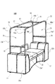
- the care bed of the sixteenth aspect since the reservoir is provided in the bed main body, the use aspect in which the reservoir and reclining are combined, for example, the mat and the frame on the leg side of the care recipient By performing the reclining in a state where the arm is removed, the care recipient can sit with the legs bent while the backrest is provided. Therefore, it is possible to provide a care bed that can be used in a state where a care recipient is sitting on a chair.
- the water storage tank is supported not only by the lower part of the floor part of the bed body but also by the support member provided inside the side part, so that it can withstand a large weight. Be able to.
- the nursing bed of the nineteenth aspect by allowing the support column to be divided into a part that appears from the bed body and a part that is driven in the support base, the part that appears from the bed body when the support column is not necessary Removing it makes it easier for the caregiver to take care of it, and also makes the appearance cleaner.
- the care bed of the twentieth aspect since the lifting device provided on one support base and the lifting device provided on the other support base are interlocked, the bed main body is lifted and lowered. This makes it possible to prevent the care recipient from having an unreasonable posture.
- the appearance of the care bed can be formed of any one of wooden, leather, metal, synthetic resin, or a combination thereof, so that it looks warm. Since it can give a high-class feeling, it can be installed as an indoor interior without a sense of incongruity, and it is possible to give comfort to care recipients and caregivers.
- wood, cedar, etc. can be used as wood, and what impregnated or apply
- surface treatment with leather material or the like can be performed.
- the synthetic resin material can be processed such as wood grain.
- the care bed of the twenty-second aspect it becomes possible to install daily necessities such as TVs, mirrors, various shelves, etc., which are difficult to install with the conventional care bed, and the caregiver's care needs Since it can also be placed, it is possible to provide a care bed that is comfortable for the care recipient and easy for the caregiver to care for. Furthermore, in addition to the daily necessities, rehabilitation instruments and the like can be provided, and rehabilitation can be performed on the care bed.
- daily necessities such as TVs, mirrors, various shelves, etc.
- the control unit of the safety device can also control operations other than the lifting device, for example, stop operation when it seems to drown during reclining operation or bathing, or when it is about to fall from the bed body Or an alarm such as a buzzer can be sounded.
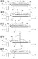
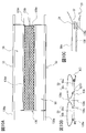
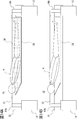
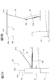
- FIG. 3A is a cross-sectional view taken along line IIIA-IIIA in FIG. 1, and FIG. 3B is a cross-sectional view showing a use state continuing from FIG. 3A.
- 4A is a cross-sectional view taken along line IVA-IVA in FIG. 1, and FIG. 4B is a cross-sectional view showing a use state continuing from FIG. 4A.
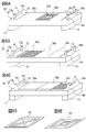
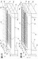
- FIG. 5A is a perspective view showing how the nursing bed according to the first embodiment is used, and FIG. 5B is a perspective view showing a flow following FIG. 5A.
- FIG. 6A is a perspective view showing another usage mode of the care bed of Embodiment 1
- FIG. 6B is a perspective view showing a usage mode different from FIG. 6A
- FIG. 6C is a usage mode further different from FIG. 6A.
- 6D and 6E show other examples of the frame.
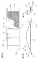
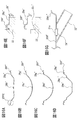
- FIG. 7A to FIG. 7E are side views showing a partial cross section showing a use mode including a care recipient.
- 8A is a perspective view showing a state in which a hammock is attached to a rod-shaped body
- FIG. 8B is a perspective view showing a state in which the hammock is divided
- FIG. 8C is a side view of the hammock.
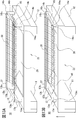
- FIG. 9A is a perspective view showing a flow subsequent to FIG.
- FIG. 9B is a perspective view showing a flow following FIG. 9A.
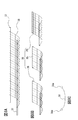
- 10A is a top view showing a hammock of still another shape
- FIG. 10B is a side view seen from one side
- FIG. 10C is an enlarged view of the XC portion of FIG. 10B.
- 11A is a top view showing a hammock of still another shape
- FIG. 11B is a side view seen from one side
- FIG. 11C is an enlarged view of the XIC portion of FIG. 11B.
- 12A is a perspective view showing a flow following FIG. 11B
- FIG. 12B is a perspective view showing a flow following FIG. 12A.
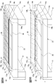
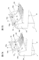
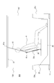
- FIG. 13A is a perspective view illustrating a usage mode of bathing of the care bed according to the first embodiment
- FIG. 13B is a perspective view illustrating a flow following FIG. 13A
- FIG. 14A is a side view showing a partial cross section showing a state where a care recipient has taken a bath
- FIG. 14B is a view showing a state where a hammock is removed from the state shown in FIG. 14A
- FIG. 15A is a top view showing a water tank of still another shape
- FIG. 15B is a cross-sectional view taken along line XVB-XVB in FIG. 15A
- 16A is a cross-sectional view taken along line XVIA-XVIA in FIG. 15B, FIG.
- FIG. 16B is a cross-sectional view taken along line XVIB-XVIB in FIG. 15B
- FIG. 16C is a cross-sectional view taken along line XVIC-XVIC in FIG. 16D is a cross-sectional view taken along line XVID-XVID in FIG. 15B
- FIG. 16E is an enlarged view of the XVIE portion in FIG. 16A
- FIG. 16F is a cross-sectional view in a state where the configuration of FIG. 16G is an enlarged view of the XVIG portion of FIG. 15B.
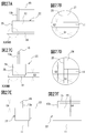
- FIG. 17A is a perspective view showing a state in which another hammock is further raised
- FIG. 17B is a perspective view showing a state in which it is lowered.
- FIG. 18A is a perspective view showing another configuration of the belt body of the hammock shown in FIG. 17, FIG. 18B is an enlarged view of the XVIIIB portion of FIG. 18A, and FIG. 18C shows a belt body of still another hammock.
- FIG. 19A is a view corresponding to FIG. 18A showing the configuration of another belt body
- FIG. 19B is a view corresponding to FIG. 18A showing still another belt body.
- FIG. 20A is a diagram illustrating still another hammock
- FIG. 20B is a schematic diagram illustrating a usage state of the hammock illustrated in FIG. 20A.
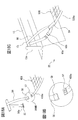
- FIG. 21A is a perspective view showing a flow of usage of reclining of a care bed according to the second embodiment, and FIG.
- FIG. 21B is a perspective view showing a flow following FIG. 21A.
- FIG. 22A is a side view showing a state in which reclining is not performed, showing a configuration of another reclining
- FIG. 22B is an enlarged view of a part of the upper surface
- FIG. 22C is a rear view of an enlarged part. is there.
- FIG. 24 is a side view of the reclining configuration of FIG. 23 in a reclined state.
- 24A to 24C are enlarged side views showing the relationship between the moving groove of the reclining cam plate and the moving axis of the shaft.
- FIG. 25A is a side view showing a further flat state of reclining
- FIG. 25B is a side view showing a state where the reclining is raised.
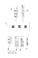
- FIG. 27A to 27F show the safety structure of the care bed. It is the block diagram which showed the safety device.
- FIG. 29A and FIG. 29B are perspective views showing modifications of the care bed.
- 30A and 30B are perspective views showing other usage modes of the modified example of the care bed. It is an exploded view of the modification of a care bed. It is the perspective view which showed the modification of the nursing bed of another shape. It is the perspective view which showed the modification of the nursing bed of another shape.
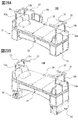
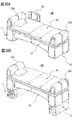
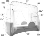
- the care bed 10 according to the first embodiment includes a bed body 22 for a care recipient to sleep and a pair of support bases 11 and 12 on which the bed body 22 is supported. Are arranged at both ends in the longitudinal direction, and further include a lattice-like frame body 33 and a mat 36.
- the pair of support bases 11 and 12 are each provided with a lifting device 16 that lifts and lowers the bed main body 22.
- the lifting device 16 includes a known electric actuator.
- the raising / lowering apparatus 16 can also use what can raise / lower the bed main body 22, for example, a jack, a winch mechanism, etc.
- the jack or winch mechanism may be electrically operated or manually operated. If it is electrically operated, a caregiver can easily raise and lower it, and if it is manually operated, it can be manufactured at low cost.
- it may be a combination of electric and manual, and can be manually performed when it cannot be performed electrically during a power failure or the like. Since this actuator, jack, and winch mechanism are well known, detailed description thereof is omitted. Each configuration will be described below.
- the pair of support bases 11 and 12 are disposed at both ends in the longitudinal direction of the bed body, but have the same configuration, and thus represent one support base 11 (hereinafter simply referred to as “support base”). I will explain.
- the support 11 has substantially the same length as the width direction perpendicular to the longitudinal direction of the bed main body 22, and the lifting device 16 for raising and lowering the bed main body 22 is housed therein. It is formed of a rectangular parallelepiped having a space.
- the rectangular top surface 11a of the rectangular parallelepiped, later struts 13a, 13b are top through hole 11a 1 pair vertically movable of is formed through, also, is connected to the upper portion of the bed body 22 of the elevating device 16
- An opening 11 a 2 through which the portion moves is formed at a substantially central portion of the upper surface of the support base 11.
- side portions 11b, 11c, 11d, and 11e are formed on the periphery of the rectangular top surface 11a, and a bottom surface 11f is provided on the lower side facing the top surfaces of the side surfaces 11b to 11e. It has been.
- the bottom surface 11f is a part installed on the floor surface in the room. Therefore, it may be the bottom surface providing a number of legs 11f 1 to a portion in contact with the floor surface. By providing the legs 11f 1, it is possible to suppress the scratching on the floor.
- the pair of support columns 13a and 13b provided on the support base 11 are each formed of a cylindrical body, and the beam member 15 is parallel to the width direction of the bed body in the direction in which the pair of support columns on the upper side face each other. It is provided so that a pair of support
- the support bases 11 and 12 and the pillars 13a, 13b, 14a, and 14b are subjected to antibacterial treatment, and the support base and the pillars can be kept clean by performing the antibacterial treatment. It is possible to suppress odor from the infection and the support stand and support column.
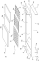
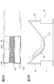
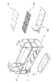
- the bed main body 22 has a floor portion 23 formed in a rectangular shape with a predetermined area and thickness that allows a person to sleep, and an opening 23 a is provided in the center portion of the floor portion 23. Further, in this floor portion 23, a floor through hole 23b through which the support columns 13a, 13b, 14a, 14b provided in the pair of support bases 11, 12 described above corresponds to the support columns 13a, 13b, 14a, 14b. Is provided. A lattice-shaped frame 33 and a mat 36 are detachably provided in the opening 23a formed in the floor 23.
- side portions 24, 25, 26, 27 hanging downward are provided on each end side of the rectangular floor portion 23 so as to surround the floor portion 23, and cover one and the other support bases 11, 12. It is provided as follows. When the bed main body 22 is at the lower side, the side portions 24 to 27 cover the whole or substantially half of each support base, and when the bed main body 22 is at the upper side, the upper part of each support base is covered. It will be about the length. These side portions 24 to 27 are particularly effective in improving the appearance of the care bed 10, and the support bases 11 and 12 and the water storage tank 28 are covered so as to obstruct care recipients and caregivers. Various decorations that do not become possible may be applied, or the shape may have a beautiful appearance. In addition, it is preferable that the bed main body 22 has been subjected to antibacterial treatment, and by performing the antibacterial treatment, the bed main body can be kept clean, and infection and odor from the bed main body can be suppressed. .
- the bed main body 22 and the support bases 11 and 12 are configured as separate bodies, when repair or replacement is performed, it can be performed for each configuration of the bed main body or the support base, and the entire care bed is repaired. And there is no need for replacement, and manufacturing and repair costs are reduced. In addition, since the pair of support bases having the same configuration is used, the manufacturing cost can be suppressed.
- the water storage tank 28 is provided inside the bed main body 22 and is formed of a box-like body having an upper opening corresponding to the opening 23 a of the floor 23.
- a plate-like support fixing portion 29 protruding toward the outside of the opening is provided along the outer periphery of the opened portion of the water storage tank 28.
- the support fixing portion 29 is supported and fixed to the lower portion 23 c of the floor portion 23.
- a support plate 30 is provided across the side surface portions 24 and 25 so as to support the lower portion of the water storage tank 28 from the side surface portions 24 and 25 opposed to each other in the longitudinal direction of the bed body 22. 28 loads can be supported (see FIG. 4A).
- the water storage tank 28 may be detachably provided inside the bed body (see FIG. 31). In that case, the floor of the bed body is removed and the water tank is attached or detached. By doing in this way, when a water tank is damaged, it can replace
- the water storage tank 28 is provided with a drain port 31 provided with an openable / closable plug member 31a.
- the plug member 31a When storing water or hot water in the water storage tank 28, the plug member 31a is closed, and when draining. The plug member 31a can be opened (see FIG. 16G).
- a drain pipe 32 is connected to the drain port 31.
- the drain pipe 32 can be connected to a drain tank to drain water.
- the drain pipe 32 may be directly connected to a sewer pipe or the like capable of draining the house.
- the water storage tank 28 is formed with an inclined portion 28a (see FIG. 2) such that the head side is inclined when a care recipient takes a bath.
- the water storage tank 28 is provided with a coating that is difficult to get dirty and easy to clean even if it becomes dirty. You may give it. Furthermore, since the water storage tank 28 is supported and fixed inside the bed main body 22 and a care recipient also takes a bath, it can withstand the weight of the stored water and the weight of the care recipient. In addition, it is preferably formed of a lightweight material such as a synthetic resin material or a metal such as stainless steel. If it is a synthetic resin material, it will become easy to perform the coating for the purpose of contamination prevention, and if it is stainless steel, a high strength water tank can be obtained. Furthermore, the strength can be further increased by forming them in a wave pattern. Moreover, it is preferable that the water storage tank is subjected to antibacterial treatment. By performing the antibacterial treatment, the water storage tank can be kept clean, and infection to a care recipient and smell from the water storage tank can be suppressed.
- a grid-like frame body (hereinafter, also simply referred to as “frame body”) 33 covers an opening 23 a formed in the floor portion 23 of the bed main body 22 and a water storage tank. 28 is configured to be locked to the bed main body 22 by a locking portion 34 provided on the outer periphery of the frame 33.
- the frame 33 is divided into a plurality of parts. For example, in the first embodiment, the frame 33 is divided into three parts: a frame 33a of the upper body part of the care recipient, a frame 33b of the waist part, and a frame 33c of the lower limb part. ing. Thus, the caregiver can easily handle the frame by dividing the frame.
- this frame 33 Since this frame 33 is often exposed to liquids such as water depending on the use mode of the care bed 10, it can support the weight of a care recipient, is resistant to rust and corrosion, and is also detachable. It is preferable to use a lightweight material, for example, a synthetic resin material such as reinforced plastic, a stainless material, an aluminum alloy, or the like. Further, it is preferable that the lattice portion 35 of the frame 33 is formed with a width that does not fit even if the care recipient rides directly on the lattice portion 35 of the frame 33.
- an opening 33b ′ may be provided in the lattice so that the excretion can be performed from this portion, and the shape of the portion that contacts the waist is excreted.
- You may make it form in easy shape, for example, the shape (not shown) of a valve seat.
- the mat 36 is a part where a care recipient goes to bed, and is detachably placed so as to cover the upper side of the lattice-like frame 33.
- the mat 36 is divided into a plurality of pieces in the same manner as the lattice-like frame body 33 described above.
- the mat 36a for the upper body of the care recipient, the mat 33b for the lower back and the mat for the lower limbs. 33c is divided into three.
- the number of mats to be divided is not limited to three.
- the upper body part may be divided into two to be four, or more.
- the care bed 10 of Embodiment 1 shown in FIG. 5 shows a state when a care recipient needs to go to bed. That is, in the bed main body 22 provided on each of the support bases 11 and 12, all the openings 23 a of the floor 23 are covered with the frame 33 and the mat 36. At this time, as shown in FIG. 5A and FIG. 5B, by operating the lifting device 16 and changing the height of the bed main body 22, the caregiver can make it easy to care for the care recipient. Become. For example, the bed main body 22 may be lowered when the care recipient needs to go to bed or when moving between a wheelchair and a care bed.
- a bed 39 is provided on the bed body for preventing the fall (see FIG. 29A).
- the usage aspect of the raising / lowering apparatus provided in the inside of a pair of support stand 11 and 12 is mentioned later.
- the mat 36 provided on the bed main body 22 is divided, mats having different materials and feels can be exchanged in divided units according to the preference of the care recipient. For example, a material having a different coefficient of restitution, a material having good air permeability, a material having waterproofness, a material corresponding to a diseased part, and the like can be selected. Further, since the mat 36 is divided, washing and drying can be easily performed. By doing in this way, not only the sleeping comfort of the care recipient but also the caregiver's ease of care can be positively affected.
- the mat 36 is preferably subjected to antibacterial treatment. By performing the antibacterial treatment, the mat can be kept clean, and infection to the care recipient and odor from the mat can be suppressed.
- the mat 36 can be removed simply by lifting a part of the body of the care recipient and pulling out the mat 36, so that the burden on the caregiver can be reduced. Become.
- the lattice is subjected to an antibacterial treatment. By performing the antibacterial treatment, the lattice can be kept clean, and infection to a care recipient and smell from the lattice can be suppressed.
- the water storage tank 28 is provided with the drain outlet 31 as described above, and the drain outlet 31 is configured to be opened and closed. Yes.
- a drain pipe 32 is connected to the drain port 31 and is piped inside the bed body 22, and an end thereof is directed to the outside of the bed body 22.
- a drain tank or the like for draining is provided at the end of the drain pipe 32.
- the drainage accumulated in the water storage tank 28 is stored in the drainage tank T or the like through the drainage port 31 and the drainage pipe 32 due to the natural fall due to gravity due to the bed main body being arranged upward. Thereafter, the drainage tank T or the like is poured into the sewage from a household toilet or the like.
- the drainage pipe 32 can be drained smoothly by having a slight inclination.
- the drain pipe 32 can be directly connected to the sewage without temporarily accumulating in the drain tank or the like.
- a simple pump can be used, in this case, it is necessary to pay attention to maintenance of the simple pump, for example, clogging of the pump.
- the drain outlet, drain pipe and drain tank are antibacterial treated, and the antibacterial treatment can keep the water tank clean and prevent infection and smell from the water tank. Can be suppressed.
- the mat 36 can be washed by removing the upper body mat 36a (see FIGS. 6B and 7B), and the lower limb mat 36c can be removed to wash the legs. Can be performed (see FIGS. 6C and 7C). Further, the footbath can be performed by removing the mat 36c and the frame 33c (see FIG. 2) of the lower limbs and filling the water storage tank 28 with hot water. Furthermore, as shown in FIG. 7D, the mats of the lower back and lower limbs can be removed and seated on the frame, and footbath can be performed. Also, as shown in FIG. 7E, all the mats can be removed. An example of a usage mode for removing all mats will be described later.
- a hammock 38 as a lifting member is attached to the care bed 10, and a mat 36, a futon and a sheet (not shown) placed on the floor portion 23 of the bed body 22. How to exchange will be described.
- the bed main body 22 in which the care recipient is sleeping is placed upward as shown in FIG. 5B using the lifting device 16 from the low state shown in FIG. 5A, and is used as a lifting member under the care recipient.
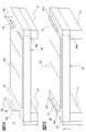
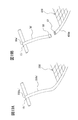
- a hammock 38 is arranged. Then, as shown in FIGS.
- a pair of rod-like body 37, the upper end portion 13a 1, 13b 1, 14a 1 , 14b 1 of the strut provided on each support platform 11 and 12, one of the support base 11 pillars 13a, 13b and the pillars 14a, 14b of the other support base 12 are attached in parallel with the longitudinal direction of the bed main body 22.
- attachment portions 13a 3 , 13b 3 , 14a 3 , 14b 3 for example, a protrusion-like locking protrusion is provided at the upper end portion of the support column, and a locking groove for engaging the locking protrusion is provided on the rod-shaped body. It can be performed by providing and fitting these locking projections and locking grooves.
- the hammock 38 as a lifting member is formed with a length that exceeds the height of the care recipient in order to lift the care recipient.
- a material having resistance capable of lifting a person who needs care for example, a material knitted with nylon or glass fiber can be used.
- the hammock 38 is divided into a plurality as shown in FIG 8B, when mounted a plurality of hammock 38 1-38 3 to the rod-like body 37, it is configured for use as a single hammock Yes.
- the rod-shaped body 37 is attached to each support
- the attachment of the hammock 38 to the rod-shaped body 37 is performed by making a ring 38a through which the rod-shaped body can penetrate the longitudinal end of the hammock 38 and penetrating the rod-shaped body 37 into the ring 38a (see FIG. 8C).
- the ring 38a formed on the hammock 38 is made of the same material as the hammock so as to be able to support the weight of the care recipient, but the inside of the ring 38a is hollow and should be flattened when a load is applied to the ring. Can do.
- the hammock 38 can be attached to the rod-like body 37 after the rod-like body is attached to each column.
- a metal hook or the like can be used.
- the rod-shaped body 37 also requires strength to support the weight of the care recipient who is lifted by the hammock 38, and is lightweight so that the caregiver can attach and detach, for example, a metal material or a synthetic resin material. It can be formed of a long pipe or hard wood.
- the hammock can be divided and attached as shown in FIG. 8B.
- Partial use is also possible, such as attaching to and using.
- the hammock and the rod-shaped body are subjected to antibacterial treatment, and the hammock and the rod-shaped body can be kept clean by performing the antibacterial treatment. Can be suppressed.
- It is also possible to suspend the hammock in the longitudinal direction by making the rod-like body attached to the upper end of the column parallel to the short direction of the bed body (not shown). By doing in this way, it is suppressed that the longitudinal stick state and the belt body of the hammock attached to the stick state obstruct caregivers' care work, and more stable care work can be obtained. .
- a curtain can be hung on the rod-shaped body.
- a shower curtain can be provided at the time of showering, and a blindfold or sun protection curtain can be provided at the time of sleeping.
- a hammock 38 on which a care recipient is placed is attached to a rod-like body 37, and the rod-like body 37 is attached to each column 13a, 13b, 14a, 14b.
- the rod-shaped body 37 can be easily attached.
- the upper ends 13a 1 , 13b 1 , 14a 1 , 14b 1 of the columns 13a, 13b, 14a, 14b and the floor 23 of the bed main body 22 are relatively close to each other. Therefore, the distance for lifting the rod-shaped body 37 is shortened, and the rod-shaped body 37 can be easily attached.
- the bed body 22 is lowered using the lifting device 16. If it does in this way, according to the fall of the bed main body 22, the support
- the care bed lifting member and the lifting device of the first embodiment it becomes possible to easily lift a care recipient from above the mat, and it is easy to replace the mat or the sheets laid on the mat. Will be able to keep the bed clean.
- each of the pair of support bases 11 and 12 is provided with support pillars 13a, 13b, 14a, and 14b, and the support pillars that protrude from the bed main body 22 when the bed main body 22 is raised and lowered.
- the lengths of 13a, 13b, 14a, and 14b vary.
- the structure of the bed main body 22 and the columns 13a, 13b, 14a, 14b and the lifting device 16 will be described in the same manner as a representative example of the support base 11.
- One actuator 16 is provided at the center position of the support base 11.
- the transmission mechanism 19 includes a central portion 20 1 of the support 11 which is fixed to the fixed member 20 Toko of the fixing member 20 is rotatably supported It is comprised with the rotation member 21 attached so that rotation was possible.
- the support 11 is provided with support columns 13 a and 13 b that respectively penetrate the upper surface through-hole 11 a 1 of the upper surface 11 a of the support 11 and the floor through-hole 23 b of the floor 23 of the bed body 22.
- both end portions of the rotating member 21, second pivot 18 1 and the support 13a of the lower portion of the extending member 18 are respectively rotatably connected to the first pivot 13a 2, 13b 2 of the lower portion of 13b.
- the extending member 18, the transmission mechanism 19, and the support columns 13 a and 13 b are provided in pairs symmetrically about the actuator 16. In this way, when the actuator 16 moves up and down, the bed main body 22 also moves up and down in accordance with the movement of the operating portion 17 of the actuator, and the vertical movement of the bed main body 22 is applied to the extending member 18 from the floor portion 23. As the extension member 18 moves up and down, the rotation member 21 pivotally supported by the fixed member 20 pivots around the pivotally supported portion, and this pivoted motion is transmitted to the columns 13a and 13b. It will be.
- this raising / lowering apparatus 16 is provided in both the one support stand 11 and the other support stand 12, the bed main body 22 can be raised / lowered in parallel. Further, it struts 13a, 13b, 14a, so even lifting of 14b can be performed in parallel, posts 13a, 13b, 14a, upper portion 13a 1 and 14b, 13b 1, 14a 1, 14b 1 of the mounting portion 13a 3, 13b 3 , 14 a 3 , 14 b 3 can also be lifted and lowered in parallel, and the care recipient on the hammock 38 attached to the rod 37 can also be lifted stably and safely.
- the bed body can be moved up and down without being inclined, It can provide a sense of security and increase safety.
- a guide rail (not shown) can be provided between the inner side of the bed main body 22 and the writing supports 11 and 12, for example, in the gap g. By providing the guide rail, it is possible to suppress the shaking of the bed main body when it is raised and lowered.
- a bed main body is lowered
- the floor part of a bed main body can be made lower by designing the thickness of a bathtub thinly, a care recipient can also suppress the injury by fall etc.
- the strut may be provided with one long member or may be divided into two.
- the portion appearing from the bed main body and the portion driven inside the support base may be detachably separated, and the portion appearing from the bed main body may be detached and attached as necessary.
- This attachment / detachment is preferably performed by screwing.
- the support column cannot be turned and cannot be easily removed, so that the safety in use can be improved.
- the transmission mechanism that interlocks the lifting and lowering of the bed body and the lifting of the support column is described when the bed body and the support column are raised and lowered is not limited thereto, and the transmission mechanism is not provided. It can also be configured as follows. That is, it is common that the bed main body moves up and down by the operation of the actuator, but the bed main body moves up and down by arranging the column fixed on the upper surface of the support base, but the column does not move up and down.
- the position of the upper end of the column does not change, so when the bed main body rises, the floor of the bed main body and the position of the upper end of the column come closer, while when the bed main body descends, the bed main body
- the positions of the floor portion of the bed and the upper end portion of the support column are moved away from each other, and the relative displacement between the floor portion of the bed body and the upper end portion of the support column can be obtained.
- the transmission mechanism when the transmission mechanism is not provided, it is not necessary to connect the support column to the transmission mechanism, so that the support column can be provided on the side surface of the support base or at a position away from the bed body. Therefore, it is not necessary to form a through hole in the floor portion of the bed body, and the manufacturing process can be simplified. Also, one bed can penetrate the floor and the other column can be arranged in a variety of layouts, such as being placed away from the bed body. Will be able to provide.
- the actuator can be provided not only in the central part of the support base but also on both sides. By doing so, it is possible to move up and down more stably, and it is also possible to adopt a smaller one as compared with the case where there is one actuator, so the support base can be made compact. In addition, when two actuators are provided, it is good to make these raising / lowering interlock
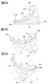
- the configuration of another hammock will be described with reference to FIGS. 10A to 10C.
- the rod-shaped body 37 is attached to the upper ends 13a 1 , 13b 1 , 14a 1 , 14b 1 of the support columns 13a, 13b, 14a, 14b of the support bases 11 and 12 and 13a 3 , 13b 3.
- 14a 3, attached to 14b 3 had done lifting and hanging down hammock 38 by raising and lowering the support table, in this hammock, attachment portion 13a 3 of the belt body constituting the hammock without a rod-shaped body , 13b 3 , 14a 3 , 14b 3 .
- the 10A is formed with a length that exceeds the height of the care recipient, and is knitted with a durable material that can lift the care recipient, such as nylon or glass fiber. Can be used.
- the belt body 138a is provided at both ends in the longitudinal direction of the hammock.
- the slide member 50 includes a fixed sheet portion 50a mounted on the hammock 138, and a slide sheet portion 50b formed longer than the fixed sheet portion 50a provided on the upper side of the fixed sheet portion 50a. These materials can be formed of, for example, nylon taffeta.
- the slide member 50 is attached by combining the end portion along the longitudinal direction of the fixed sheet portion 50a and the end portion along the longitudinal direction of the slide sheet portion 50b. Therefore, when the fixed sheet portion 50a is stretched, the slide sheet portion 50b is in a slack state.
- the slide member 50 On the belt body 138a provided on both sides along the longitudinal direction of the hammock 138, and on a pair of axes 138c positioned on the belt body 138a side of the longitudinal center line 138b of the longitudinal hammock 138 For example, detachable first tape bodies 51 are respectively attached.
- the slide member 50 has a second tape body 52 that is detachable on the fixed sheet portion 50a side at a position corresponding to the belt body 138a on both sides of the hammock 138 and the first tape body 51 attached on the axis 138c. It is attached.
- seat part 50a are attached detachably by combining the 1st tape body 51 and the 2nd tape body 52 (refer FIG. 10B and FIG. 10C).
- the fixed sheet portion 50a of the slide member 50 is attached in a stretched state on the hammock 138.
- the slide sheet portion 50b is attached on the fixed sheet portion 50a so that both ends thereof are aligned.
- This attachment may use a removable tape body as described above, or may be sewn with a thread.
- the size of the slide sheet portion 50b is such that when the slide member 50 is attached to the hammock 138, the central portion 138e of the hammock 138 is covered by the slack portion of the slide sheet portion 50b.
- the mesh 138d of 138 is covered.
- the fixed sheet portion 50a of the slide member 50 is fixed in a stretched state on the hammock 138, and the slide sheet portion 50b above the fixed sheet portion 50a is fixed.
- the portion of the sheet portion 50a that protrudes from the portion fixed by the first and second tape bodies 51 and 52 can slide in the lateral direction. Therefore, when placing a care recipient on the hammock 138, the care recipient is placed on the slide sheet portion 50b of the slide member 50, so that the care recipient is hammocked by sliding the slide seat portion 50b on the fixed seat portion 50a. It becomes easy to move to a predetermined position 138.
- the care recipient can be appropriately moved on the hammock 138, so that pain and rubbing due to bed slip can be suppressed.
- the hammock is formed in a mesh shape, if the care recipient needs to put weight on the mesh 138d, the mesh 138d bites into the body, which is painful.
- the mesh 138d is provided. Direct touching is suppressed, and pain and rubbing can be suppressed.
- the slide member 50 is attached to both sides of the hammock 138, and the mesh 138d appears in the central portion 138e by sliding the slide sheet portion 50b, so that it is possible to drain the water during bathing or shower, which will be described later. It becomes like this. Further, by attaching the hammock 138 and the slide member 50 using a detachable tape body, the attachment and detachment can be easily performed, and cleaning and replacement can be easily performed.
- a so-called ear 53 is provided on the outside of the belt body, and the ear 53 can be used for transportation or attachment to a rod-shaped body. Therefore, a plurality of ears 53 may be provided.
- the slide member is configured by the fixed sheet portion and the slide sheet portion has been described. A similar effect can be obtained by mounting in this manner.
- the slide member is composed of a fixed sheet portion and a slide sheet portion
- the slide sheet portion may be directly attached to the hammock without using the fixed sheet portion.
- the hammock having this configuration is provided with a double sheet body 54 including a first sheet body 54 a and a second sheet body 54 b on the side of the hammock 238 on which a care recipient is required.
- the double sheet body 54 includes a first sheet body 54a attached to the upper side of the hammock 238 and a second sheet body 54b attached to the upper side of the first sheet body 54a. It is formed so that the width direction of the hammock 238 is larger with respect to the first sheet body 54a.
- seat body 54a is attached in the stretched state by attaching the both ends of the 1st sheet
- the second sheet body 54b formed to be large is attached so that both ends thereof are aligned with both ends of the hammock 238, so that the second sheet body 54b is attached in a relaxed state.
- seat body 54 is divided
- each double sheet body 54 is provided with an overlapping portion 55 such that each end portion in the longitudinal direction partially overlaps the hammock so that the mesh of the hammock 238 is not exposed.
- belt bodies 238a are provided at both longitudinal ends of the hammock 238, the first sheet body 54a, and the second sheet body 54b.
- the second sheet body 54b can be slid and moved on the first sheet body 54a by the different sizes. Therefore, when a care recipient is put on the hammock 238, even if the care recipient gets on the end of the hammock 238, the care recipient can be easily moved by sliding the second sheet body 54b without directly moving the care recipient.
- the hammock 238 can be moved to a predetermined position. In addition, by sliding the second sheet body 54b, it becomes possible to suppress pain and rubbing due to bedsores when the care recipient is appropriately moved on the hammock 238.
- the hammock 238 is formed in a mesh shape, if the care recipient needs weight on the mesh 238d, the mesh 238d bites into the body, which is painful. Further, direct contact with the mesh 238d is suppressed, and pain and rubbing can be suppressed.
- the double sheet body 54 is divided into a plurality of parts, but since the overlapping part 55 where these end parts overlap is provided, it is possible to prevent the mesh 238d from touching the care recipient. it can. Further, the overlapping portion 55 is provided in the double sheet body 54 divided into a plurality of parts, so that water can be drained when a shower or the like described later on the double sheet body 54 is used.
- a so-called ear 53 is provided outside the belt body 238a, and the ear 53 can be used for transportation or attachment to a rod-like body. Therefore, a plurality of ears 53 may be provided.
- a double-sheet body is used for the transfer by the slide of the care recipient is described above, the present invention is not limited to this, and a second sheet body that can slide on the hammock may be directly provided.
- the hammock mesh portion described above may be removed, and the lifting member may be constituted only by the belt body and the slide member or the double sheet body.
- the lifting member may be constituted only by the belt body and the slide member or the double sheet body.
- the slide member may be used only in the slide sheet portion, and the double sheet body may be used only in the second sheet body constituting the double sheet body.
- the bed body 22 is raised again using the lifting device 16 as shown in FIG. 12B.
- the support pillars 13a, 13b, 14a, 14b of the support bases 11 and 12 are relatively lowered, and the rod-like body 37 and the hammock 38 are also lowered. It will be placed on the frame 33.
- the care recipient can take a shower using a shower using a water supply tank, a small pump, etc., and the drainage of the shower taken by the care recipient is stored inside the bed body 22.
- the tank 28 can be passed through the frame 33 and drained from the water storage tank 28. This drainage state is the same as described above.
- the shower can also be performed with the hammock removed while the care recipient is laid on the frame (see FIG. 7E). At this time, since the hammock is divided into a plurality, the caregiver can easily remove it even when the care recipient is laid on the frame.
- the wastewater flows into the water storage tank 28, so that the wastewater can be prevented from adhering to the care recipient. That is, if a shower is taken in the water storage tank 28, the drainage of the shower that has taken a shower accumulates in the water storage layer, which may adhere to the care recipient and is not hygienic.
- the care bed 10 according to the first embodiment can be easily performed.
- the bed body 22 is lowered again, and the hammock 38 is relatively lifted to lift the care recipient.
- the mat 36 can be placed on the frame 33 of the bed main body 22 and the bed main body 22 can be raised to place a care recipient on the mat 36.
- the hammock 38 is collected. This collection is performed under the care recipient, but as described above, the hammock is divided, so that the care recipient can easily lift the collection portion or use the flexibility of the mat 36. Yes.
- the use mode of the shower ends here.
- the moisture on the body of the care recipient may be wiped off at any time after showering, when it is lifted in a hammock, or when it is placed on a mat. Further, the water in the water storage tank 28 and the frame 33 can be wiped off at the same time. In addition, it is preferable to perform large-scale washing of the water storage tank or the like when the care recipient leaves the care bed 10.
- a water supply tank is used.
- a water tank of about 5 to 30 liters is installed, a small pump is provided in the water tank, and the shower can be performed via this small pump.
- piping work such as a water supply pipe becomes unnecessary.
- the usage aspect of the care bed 10 of Embodiment 1 when bathing a care recipient is demonstrated.
- the case where the hammock 38 as a lifting member mentioned above is used is demonstrated.
- This method of use is the same as the use mode of the shower described above. That is, as described above with reference to FIGS. 5 and 9, first, the bed main body 22 is raised, and the hammock 38 is passed under the care recipient who has been laid on the mat 36 of the bed main body 22.
- the care recipient is lifted by the hammock 38 by lowering the bed body 22. This operation is the same as described above.
- the mat 36 and the lattice frame 33 placed on the bed main body 22 are all removed, and the water storage tank 28 appears from the opening 23a of the bed main body 22.
- the mat 36 and the frame 33 are divided, the mat 36 and the frame 33 can be easily removed, and since the frame 33 is also formed in a light weight, it can be easily removed by a caregiver.
- the rise of steam from the bathtub can be suppressed by sticking a sheet to the lower side of the mat.
- a sheet member for example, a water-resistant sheet 40 is laid so as to cover the inner surface of the water storage tank 28 (see FIG. 13B).
- an attachment member such as a hook may be provided in the water storage tank 28, and a sheet may be attached to the attachment member. Since this water tank 28 is also used for excretion as described above, even if the water tank 28 is cleaned, it may become a mental burden on the care recipient who takes a bath. This reduces the burden.
- hot water is put therein. This hot water may be pumped with a simple pump or carried from a home bath.
- the sheet member is not limited to a sheet shape, and may have various shapes. For example, by forming a structure (such as an armrest) that is formed in a water tank on the sheet member, it is not necessary to form irregularities in the water tank itself, so that the manufacturing cost of the water tank is reduced and the water tank is washed. It becomes easy to do. Further, since the seat member can be easily attached and detached, the seat member can be easily exchanged, and the shape of the sheet member can be selected in accordance with the state of the care recipient. Furthermore, it is preferable that the sheet member has been subjected to antibacterial treatment. By performing the antibacterial treatment, the sheet member can be kept clean, and infection to a care recipient and odor from the sheet member can be suppressed.
- a structure such as an armrest
- the bed body 22 When the water level in the water storage tank 28 exceeds a certain level, the bed body 22 is raised. As a result of this rise, the water storage tank 28 of the bed main body 22 rises, and the care recipient who got on the hammock 38 descends, so that the care recipient can enter the hot water in the water storage tank 28. At this time, the care recipient remains on the hammock 38, but can bathe without problems if the water depth is deep (see FIG. 14A). In addition, you may remove a hammock during bathing (FIG. 14B). Since the care recipient during bathing floats due to the buoyancy of water, the hammock can be easily removed and attached.
- the bed body 22 When bathing is completed, the bed body 22 is lowered again and the hammock 38 is raised. Then, by shifting or bending a part of the sheet 40 laid on the water storage tank 28, the hot water in the sheet 40 flows into the water storage tank 28 and drains from the drain port 31 of the water storage tank 28. This drainage is the same as described above.
- the opening 23 a of the bed main body 22 is closed with the frame 33, and the mat 36 is placed on the frame 33. Then, the bed main body 22 is raised, the hammock 38 is lowered, and the care recipient is placed on the mat 36.
- the following operations are the same as described above. By doing in this way, a care recipient can be made to take a bath easily.
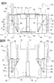
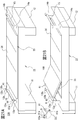
- the water storage tank 28 of Embodiment 1 is described as a box-shaped one, the present invention is not limited to this, and the water storage tank may be deformed, for example, as shown in FIGS. 15 and 16. can do.
- the water storage tank 28 "shown in FIGS. 15 and 16 is detachably provided on the inner side of the bed main body 22.
- the water storage tank main body 28a" is a box-shaped body that opens upward corresponding to the opening 23a of the floor 23. Have.
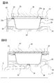
- the water tank main body 28a has a head arrangement portion 28b" on which the head of the care recipient is placed when the care recipient is stored in a sleeping state because the water tank 28 "is used as a bathtub.
- Each is formed with a predetermined depth and shape.
- a backrest portion 28c "provided at a predetermined angle on one side with the waist placement portion 28d” as a substantial center, and a head placement portion 28b “connected to the backrest portion 28c” are provided. .
- a leg portion arrangement portion 28e is provided on the other side of the waist arrangement portion 28d". At this time, the head placement portion 28b “is at the highest position, and the waist placement portion 28d" is at the lowest position.
- hook-shaped claw portions 28f “for detachably attaching to the bed main body 22 are formed on four sides of the water tank main body 28a". Then, the bed body 22 is formed with a projection 22 1 ′′ (see FIG. 16F) for hooking the claw portion 28f ′′ to attach the water storage tank 28 ′′. With such a configuration, the water storage The tank can be easily attached and detached.
- a step 28g " is formed inside the claw portion 28f" formed in the longitudinal direction of the upper surface of the water tank main body 28a ", and the frame 33 can be placed on the step 28g". ing. By doing in this way, it is not necessary to form the place of the frame 33 in the bed main body 22. Further, by supporting the lower side of the step 28g “by the bed main body 22, the strength of the water storage tank 28" and the frame 33 can be increased. In addition, it can suppress that hot water etc. overflow from this part by forming this level
- the head arrangement portion 28b becomes a portion on which the head of the care recipient is placed, supports the head when taking a bath, and can perform hair washing and the like. It has an area.
- the head arrangement portion 28b is formed so as to be slightly inclined toward the central portion of the water tank main body 28a" so that hot water used for washing the hair does not collect.
- the backrest portion 28c is formed with an inclination that can support the back portion of the care recipient. This inclination is used when the care recipient uses the water reservoir 28" as a bathtub.
- the hot water stored in the tank body 28a "does not enter the head placement section, or is positioned below the ear of the care recipient, and the body below the head of the care recipient The angle is such that the part can be immersed in hot water.
- a neck arrangement portion 28h shaped so as to fit the neck of the care recipient is provided in the central portion between the head arrangement portion 28b" and the backrest portion 28c ".
- This neck arrangement portion 28h” May be formed integrally with the water tank main body 28a ", or may be formed by another member.
- the waist placement portion 28d is a portion on which the waist of the care recipient is placed, the waist placement portion 28d" is provided at the lowest position in the water tank main body 28a ". For this reason, a drain port 31 "is provided in the waist placement portion 28d". Further, a step 28d 1 ′′ is formed between the waist placement portion 28d ′′ and the leg placement portion 28e ′′ so that the leg placement portion 28e ′′ is higher. Therefore, when the care recipient takes a bath, it becomes possible to prevent slipping by hooking the waist of the care recipient to this step 28d 1 ", and the care recipient is prevented from being immersed in the water storage. can do.
- the leg placement portion 28e " is a portion where the leg of the care recipient is placed and is formed relatively long.
- the leg placement portion 28e” is formed so as to be gently inclined toward the waist placement portion 28d ".
- the leg placement portion 28e " is formed with a narrowing portion 28e 1 " that narrows toward the portion where the toe of the care recipient is placed. This narrowing portion 28e 1 ". Is formed up to a predetermined height of the water tank main body 28a ". By providing the narrowed portion 28e 1 " in this way, the amount of water used can be reduced and water can be saved.
- the amount of water to be supplied is determined based on the top portion 28e 2 "of the narrowed portion 28e 1 ". By preventing it from exceeding 28e 2 ′′, it is possible to prevent hot water or the like from being immersed in the head of the care recipient.
- the narrowed portion 28e 1 ′′ is formed, the amount of hot water used for bathing is suppressed and water saving effect is obtained, and the weight of hot water etc. applied to the water storage tank 28 ′′ is suppressed.
- the material cost for forming the water tank 28 "can be suppressed. Can be manufactured.
- sufficient strength cannot be obtained in the sheet-like water storage tank it is preferable to provide a structure like the support plate 30 (see FIG. 4) below the water storage tank.
- the water storage tank 28 " is used by care recipients of various body types, it is preferable to form the water storage tank 28" so as to correspond to many body types. For this reason, the water storage tank 28 "is based on the waist arrangement portion 28d".
- the leg arrangement portion 28e "to be long it is possible to cope with a tall care recipient.
- the backrest portion 28c "to be short it is possible to cope with a short care recipient.
- the position of the care recipient's neck varies depending on the height of the care recipient, although the position where the neck portion arrangement portion 28h "is formed is different, this can be dealt with by arranging the neck portion arrangement portion 28h" formed of a separate member at a predetermined position or using a towel or the like. By gently forming the portion 28c ", it becomes possible to immerse the entire body in hot water or the like regardless of its height.
- the care bed 10 is preferably low in consideration of the care recipient and the caregiver's usage, for example, the movement of the care recipient from the wheelchair and the caregiver's general care. Furthermore, since the care bed 10 of Embodiment 1 can be moved up and down, it is more preferable to lower the state where the care bed 10 is lowered most.
- the care recipient's bathing will be half-bathed It can also be used for care recipients who have difficulty with full-body bathing, which places a burden on the heart, so that the reservoir can be made thinner by using a half-bath reservoir. Therefore, the height of the care bed can be made lower.
- drain pipe 32 "connected to the drain port 31" is also attached obliquely as shown in FIG. 16G, or the drain pipe is formed in an L shape so that the bed body 22 is arranged in a lower state. Will be able to.
- FIGS. 17A and 17B another configuration of the hammock lifting and hanging will be described.
- one of the support bases is shown as a representative, but the other support base has the same configuration.
- the head body 22a is provided on the bed main body 22. Therefore, you may make it provide a foot board in the bed main body by the side of the other support stand.
- the hammock 338 is provided with belt bodies 338 a that are longer than the length of the hammock 338 at both ends along the longitudinal direction of the hammock 338.
- the end of the belt member 338a Each strut 13a of the support base 11, through the upper beam member 15 mounted over a 13b, a belt member 338a to the floor mounting portion 22 1 of the floor portion 23 of the bed body 22 Part 338a 1 is attached.
- the end portion 338a 1 is provided with a mounting bracket or the like.
- the belt body 338a may be provided with a structure capable of adjusting the length of the belt body 338a, such as a buckle.
- the hammock 338 lifting, and the end portion 338a 1 of the belt member 338a hammock 338 attached to the bed body 22 by lowering the bed body 22 is lowered, accordingly, provided on the support base 11
- the beam member 15 attached to the columns 13a and 13b is also raised.
- the belt member 338a that is disposed over the beam member 15, the belt member 338a ends 338a 1 is lowered, the portion of via the beam member 15 between the end portion 338a 1 and hammock 338
- the belt body 338a comes to rise. Therefore, the hammock 338 can increase the distance approximately twice the descending distance of the bed main body 22. The same process is performed when the hammock 338 is suspended.
- the hammock 338 can be suspended by the lowering of the belt body 338a (see FIG. 17B).
- the lifting of the hammock with this configuration is not limited to the case where the support column is moved up and down in conjunction with the lifting and lowering of the support table, but can also be applied to the case where the support column is not interlocked with the lifting and lowering of the support table.
- the moving distance such as lifting of the hammock is substantially the same as the lifting distance of the support base, but since the structure can be simplified, the care bed can be provided at low cost.
- 17A and 17B illustrate the case where the head body is provided on the bed body, but the present invention is not limited to this, and the present invention can also be applied to an apparatus without a head board as shown in FIG. .
- the belt body 338a when the belt body 338a is provided in the hammock 338, the belt body 338a becomes long, and therefore, the end of the belt body 338a may be swung around the hammock 338 and attached to the care recipient or caregiver. In addition, there is a risk of damage if it hits an object. Note that the end of the belt body 338a needs to be securely attached to the bed body 22, and is formed of metal or the like in order to obtain strength, and the risk of injury or damage becomes significant. Therefore, it is preferable to make the belt body provided in the hammock as short as possible.
- the hammock 438 shown in FIG. 18A, the belt member 438a as the lifting belt member is provided on the hammock 438 short and mounting the belt attached to the floor mounting portion 22 1 of this is connected to the belt member 438a bed body 22
- the belt body 56 is used as a body. Connection between the belt member 56 of the belt member 438a and another of the hammock 438, the floor mounting portion 22 1 of the bed body 22 of the first coupling portion 57 and the belt member 56 provided at an end portion of the belt member 438a This is performed by coupling the end 56a on the side to be attached to the second coupling portion 58 attached to the end on the opposite side (see FIG. 18B).
- the first coupling portion 57 and the second coupling portion 58 are made of metal or the like.
- the belt body 438a provided in the hammock 438 can be shortened, so that the first coupling portion 57 at the end of the belt body 438a is narrowed even when the hammock 438 is attached or detached. Since it is a range, hitting a care recipient or the like can be suppressed and safety can be improved.
- first and second coupling portions 57 and 58 can be easily attached and detached by making the first coupling portion 57 and the second coupling portion 58 detachable with a single touch.
- bond part 58 can use what is marketed.
- a belt body 538a as a lifting belt body is provided on the hammock 538, but a metal coupling portion is not provided at an end thereof, and the end of the belt body 538a is rounded and formed in an annular shape. An annular portion 59 is formed.
- a belt body 60 is provided as an attachment belt body formed of a separate member from the hammock 538.
- the belt body 60 is provided with detachable metal connection portions 60a and 60b for coupling one end and the other end, respectively, and the connection portions 60a and 60b are connected to form a loop shape. It is used in this way.
- the belt body 60 may be provided with a structure for adjusting the length of the belt body 60 to be used. This adjustment may be performed at the connection portions 60a and 60b, and a buckle or the like may be provided on the belt body 60.
- the method of attaching the hammock 538 is as follows. First, the belt-like belt body 60 in a state where the connecting portions 60a and 60b are not connected is inserted through the annular portion 59 of the belt body 538a of the hammock 538, and the beam member 15 is disposed inside. The connection is completed by connecting the connection portions 60a and 60b of the belt body 60 in a loop shape so as to be disposed in the belt. In this case the belt body 60 may also be so attached to the attachment portion 15 1 provided on the beam member 15. When the hammock 538 is lifted, the bed main body 22 is lowered, and the beam member 15 attached to the column 13a (13b is not shown) is lifted, whereby the hammock 538 is pulled by the belt body 60, and the hammock 538 is lifted. It is done. By doing in this way, since the metal member is not provided in the belt body 538a of the hammock 538, safety
- FIGS. 17A and 17B shows the case of attaching the ends 338a 1 of the belt member 338a of the hammock 338 floor mounting portion 22 1 formed in the floor portion 22 is not limited to this, FIG. 19A as shown in, it may be attached to the attachment portion 15 1 provided on the beam member 15. In this way, the structure than provided floor mounting portion 22 1 is simplified to the floor section 22. Further, even if the error occurs when the mounting portion 15 1 of the beam member 15, while continuing to use the nursing bed, can be performed only replacement of the beam member.
- the attachment of the belt member to the mounting portion 15 1 of the beam member 15, as shown in FIG. 18A, divided belt body 56 of the hammock 438 'to the belt body 438a, the belt body the 'end 56a of the' 56 may be to attach the mounting portion 15 1 of the beam member 15.
- the first coupling portion 57 of the hammock 438 and the second coupling portion 58 of the belt body 56 ′ can be attached and detached with one touch in the same manner as the configuration shown in FIG. 18B. With this configuration, the first and second coupling portions 57 and 58 can be easily attached and detached.
- a hammock 138 ′ as shown in FIG. 20A can be used.
- a hammock 138 ′ shown in FIG. 20A is provided with a mesh 138d ′ on which a care recipient H rides approximately half the length of the hammock 138 ′ and a slide member 50 ′.
- 138a ′ has the same length as described above.
- the hammock 138 ′ is configured as described above, when the person requiring care is lifted, it can be performed in a sitting state as shown in FIG. 20B. Anxiety to the person can be suppressed.
- FIG. 20 although it showed using the structure of the lifting member demonstrated in FIG. 10, it is good not only as this but the structure which made the lifting member of another structure substantially half.
- a hammock is used as a lifting member.
- the present invention is not limited to this, and a sheet laid on a mat can be used as the lifting member.
- a belt body like that used in the above-mentioned hammock is provided at both ends in the longitudinal direction of the sheet so that the structure can be connected to a column or a bed body.
- These configurations are common to the belt body used in the above hammock. By doing in this way, since it can lift using the bed sheet which the care recipient requires, the operation
- the sheets need to have a material and a structure that can support the weight of the care recipient when the sheets are lifted.
- the care bed 10A of Embodiment 2 is configured such that the upper body part can be reclined so that a care recipient can easily eat or read.
- each strut 13a provided on one of the support base 11, the upper end portion 13a of 13b 1, 13b 1 of the mounting portion 13a 3, 13b 3 and the support side of the grid-shaped frame body 33 end 33 1 and the connecting member 41 for example, it is done by connecting a wire or rope, a plate-like body or the like.
- symbol is attached
- the attachment portions 13a 3 and 13b 3 are provided on the upper end portions 13a 1 and 13b 1 of the support columns 13a and 13b so that the rod-shaped body 37 can be attached thereto. For this reason, by providing, for example, a ring that can be attached to the protrusions of the attachment portions 13a 3 and 13b 3 of the upper ends 13a 1 and 13b 1 of the support columns 13a and 13b at the one end 41a of the connection member 41, for example.
- the connection can be made easily and can be made difficult to come off.
- the end portion 33 1 of the frame body the other end can be connected structure of the connection member 41, for example, pendent protrusion, or a through hole or the like is provided, to the other end 41b connected to connecting member 41 to the portion .
- the structure of the other end of the connection member 41 for example, a ring through which a hanging protrusion passes can be provided, or a hook or the like that can be connected to the through opening can be provided (see A part in FIG. 21B).
- the bed main body 22 is moved downward.
- the respective struts 13a, upper portion 13a 1, 13b connecting member 41 connected to one 13b is moved upward.
- it connected so member 41 also moves upward
- the end 33 1 of the other end 41b and connected to a frame member of the connecting member 41 also becomes possible to move upward
- the frame 33 is a connecting member It inclines so that the side to which 41 is connected becomes upward.
- the other side of the frame 33 is provided on the bed body 22 and moves downward, so that the inclination of the frame 33 can be made larger than the moving distance of the lifting device 16. .
- the mat 36 placed on the frame 33 is bent along the inclination of the frame 33 (see FIG. 21B).
- a reclining mechanism 84 having an actuator 85 for reclining is provided in the bed main body 22.
- the actuator used here is not linked to the actuator used in the lifting device in the support base.
- the reclining mechanism described here is provided so as to be opposed to each other on both sides in the bed main body, but since these have the same configuration, only one side will be described as a representative.
- the reclining structure is configured such that an actuator 85 having a rod-like working pile 87 inserted and removed by a driving means 86 and an end portion 87a of the working pile 87 are rotatable.
- a plate-like link beam 88 connected and a fixing member 89 attached to a frame 33a in which an end 88a opposite to the side connected to the working pile 87 of the link beam 88 is rotatably connected.
- a link plate 90 rotatably connected with the end portion 87a of the working pile 87 and the link beam 88, and a first end portion 90a of the link plate 90 connected to the end portion 90a opposite to the side connected to the working pile 87.
- a shaft 92 movable with the rotation of the cam plate 91 is coupled to 1a, and a frame body 33a that recline with the movement of the shaft 92.
- the frame 33a is provided with an arm member 93 that is partially bent and can move up and down.
- the fixing member 89 includes a fixing part 89a attached to the lower side of the frame 33a provided with the reclining arm member 93, a rectangular side part 89b extending from the fixing part, and the side part 89b. And a pair of first and second mounting portions 89d and 89e that are bent at a right angle from the bent portion 89c.
- the side surface portion 89 b is formed to protrude toward the inside of the bed main body 22.
- a U-shaped base member 94 extending to a position adjacent to the support base 11 is attached to a portion of the side surface 89 b of the fixing member 89 on the inside of the bed main body 22.
- An actuator 85 is fixed to the support base 11 side of the base member 94.
- One of the link beams 88 connected to the end portion 87a of the operating pile 87 of the actuator 85 is rotatably connected to the operating pile 87, and the other is on the side of the fixed member 89 on the side away from the support base 11. It is rotatably attached to the first attachment portion 89d.
- the link beam 88 is a member that supports the end portion 87a of the working pile 87 so as to be movable.
- One of the link plates 90 connected to the end 87a of the operating pile 87 of the actuator 85 is rotatably connected to the operating pile 87, and the other is connected to the cam plate 91 so as to be freely rotatable. .
- the link plate 90 is a member that transmits the movement of the working pile 87 to be taken in and out to the cam plate 91.
- the cam plate 91 is formed in a substantially triangular shape, and is rotatably attached to the second attachment portion 89e on the side of the fixing member 89 adjacent to the support base 11.
- the link plate 90 is connected to one second vertex portion 91 c of the cam plate 91.
- the cam plate 91 is formed with an arcuate movement groove 91a so that the other two first and third vertex portions 91b and 91d of the second vertex portion 91c to which the link plate 90 is connected are connected. .
- the mounting position of the cam plate 91 to the second mounting portion 89e is such that the support base 11 is moved from the moving groove 91a of the first vertex portion 91b formed at a position close to the frame body 33a in the vertex portion of the cam plate 91.
- a cam fulcrum 91e that is a fulcrum of rotation of the cam plate 91 is attached at a position facing the side.
- the cam plate 91 rotates about the cam fulcrum 91e.
- a rod-like shaft 92 for reclining an arm member 93 provided on the frame 33a is attached to the cam plate 91.
- the shaft 92 moves in the moving groove 91a in the moving groove 91a of the third apex portion 91d adjacent to the support base 11.
- a possible moving shaft 92a is provided. And then.
- the moving shaft 92a can move in the moving groove 91a by the movement of the cam plate 91.
- a roller 92 b for pushing up the arm member 93 is provided on the other end side of the shaft 92.
- the shaft 92 is provided by being inserted into a guide hole formed in a guide member 95 attached to the opposite side of the protruding portion of the fixing member 89 to the side on which the base member 94 is attached.
- the working pile 87 of the actuator 85 protrudes and is in a state as shown in FIG. 22A. That is, the link plate 90 coupled to the end portion 87a of the actuation pile 87 by the projection of the actuation pile 87 of the actuator 85 causes the cam plate 91 to rotate about the cam fulcrum 91e as one end of the cam plate 91 is pulled.
- the moving shaft 92a of the shaft 92 that moves in the moving groove 91a formed in the cam plate 91 is arranged at the lowest position. Therefore, the shaft 92 itself is also lowered, and the roller 92b that pushes up the arm member 93 is also in a low position, and the reclining is not performed.
- the drive means 86 of the actuator 85 is driven, and the working pile 87 is drawn.
- the link plate 90 presses one end of the cam plate 91, whereby the cam plate 91 rotates around the cam fulcrum 91 e of the cam plate 91.
- the moving groove 91a formed in the cam plate 91 also moves, and the moving shaft 92a of the shaft 92 supported in the moving groove 91a moves along the moving groove 91a. become.
- the movement of the moving shaft 92a causes the shaft 92 itself to move upward along the guide hole in the guide member 95, and the arm member 93 is pushed up by the roller 92b provided on the other end side of the shaft 92. Will be done.
- the arm member 93 can be smoothly raised by the rotation of the roller 92b.
- a rail for guiding the roller 92b may be provided below the arm member 93. Further, since the shaft 92 moves along the guide hole in the guide member 95 attached to the fixing member 89, the shaft 92 can move linearly, so that reclining can be performed stably.
- FIGS. 24A to 24C The relationship between the moving groove 91a of the cam plate 91 and the moving shaft 92a of the shaft 92 at this time will be described with reference to FIGS. 24A to 24C.
- the moving shaft 92a of the shaft 92 is arranged at the lowest position (the third vertex portion 91d). Then, reclining is performed, and as shown in FIG. 24B, when the cam plate 91 is rotated by a predetermined angle ⁇ 1, eg, 30 °, with the cam fulcrum 91e as an axis, the moving shaft 92a becomes a circle as the cam plate 91 moves.
- the moving shaft 92a is gradually moved upward (distance L1) from the initial position by moving in the moving groove 91a formed in an arc shape. Thereafter, when the pulling of the working pile 87 is completed and the rotation of the cam plate 91 is stopped by rotating a predetermined angle ⁇ 2, for example, 60 ° (see FIG. 24C), the moving shaft 92a is moved to the other first vertex of the moving groove 91a. Moving to the portion 91b, the moving shaft 92a moves obliquely upward from the first position over a distance L2 (L1 ⁇ L2) and is arranged at the highest position. At this time, the reclining of the arm member 93 provided on the frame 33a is also inclined most (see FIG. 23).
- the reclining mechanism 84 is based on the fixing member 89 attached to the frame 33a, so that the reclining mechanism 84 can be easily attached by attaching the fixing member 89, and It can be installed even in a small space.
- the reclining mechanism 84 can be optionally attached to a care bed.
- the present invention is not limited to this, and a reclining mechanism excluding the actuator is provided on both sides of the bed main body, and only the actuator is provided at the center of the bed main body.
- a configuration may be adopted in which only one is attached to the portion, and a reclining mechanism provided on both sides of the bed main body is operated by the operation of this one actuator.
- each column 13a ′ (13b ′ is not shown) provided on the support base 11 is formed in an elongated shape, and the mounting portion 13a of the upper end portion 13a 1 ′ of the column 13a ′ is formed.
- the rod-shaped body 37 is transferred to 3 ′.
- the 1st connection part 61a provided in this rod-shaped body 37 and the 2nd connection part 61b provided in the frame 33a by the side of the head of the care recipient who performs reclining are wire, a rope, and metal rod shape. It is connected by a connecting member 61 such as a body. Further, the reclining frame 33a is configured to be bent from a part. At this time, the height of the upper end portion 13a 1 ′ of the column 13a ′ is set to be about 1.5 m to 2.5 m from the floor.
- the bed main body 22 is lifted while the care recipient is sleeping on the mat 36, and the bed main body 22 and the rod-shaped body 37 are positioned close to each other.
- the first connecting portion 61 a of the rod-shaped body 37 and the second connecting portion 61 b of the frame 33 a are connected by the connecting member 61.
- the bed main body 22 is lowered, the distance from the rod-shaped body 37 is increased, and the frame body 33a is pulled by the connecting member 61 coupled to the rod-shaped body 37, so that reclining is performed.
- the connecting member 61 is a wire or rope string-like body, and a winding device such as a winch is provided in the first connecting portion 61a of the rod-like body 37, and the bed main body is not moved up and down by moving this winding device. You will be able to recline.
- the configuration using this winding device can be realized by forming each column in a long shape and passing a rod-like body to this column.
- the structure of the reclining using this winding apparatus can also be provided independently, and can also be used together with the reclining by raising / lowering of a bed main body. In this way, each can be used separately for reclining, and can also be used as an aid for reclining by raising and lowering the bed body.
- the care bed 10A reclines in a state where the mat 36c and the frame 33c (see FIG. 2) of the lower limbs of the care recipient are removed, so that the care recipient needs the legs. It is possible to sit in a state where the water tank 28 is lowered, that is, in a state where it is seated on a chair. Conventionally, in a state where the reclining is performed, the care recipient is in a state where his / her leg is extended on the bed. In addition, it is possible to bend the leg and soak the so-called cross-legged, but it is difficult for a care recipient who is unable to use the leg, and the leg may be numb if the leg is stood for a long time.
- FIG. 26 shows the case where the reclining method shown in FIG. 25 is used, the present invention is not limited to this, and the other reclining methods described above can also be used.
- the care bed of the present invention is configured in consideration of the safety of the care recipient and the caregiver.
- an example of the safety structure provided in the care bed will be described with reference to FIGS. 27A to 27D.
- the support base is provided so that the toes or the like do not enter the side surfaces 24, 25, 27 (the side surface 26 is not shown) of the bed main body 22 on the side where the support base 11 is provided.
- the gap G ⁇ b> 1 between the side surface of the eleventh side and the side surface of the bed main body 22 is formed within a predetermined length.
- a gap G1 having a length from the side surface of the support base 11 to the side surfaces 24, 25, and 27 of the bed main body 22 is formed to be within 20 mm, for example. Yes.
- the height of the gap G2 from the floor surface to the lower side of the side surfaces 24, 25, 27 of the bed main body 22 is, for example, It is formed to be 30 mm or more.
- a predetermined height is provided between the lower side of the side surface 24 of the bed body and the floor surface in the state where the bed body 22 is lowered on the side surface 24 of the bed body 22 where there is no support base 11. For example, a gap G3 of 80 mm or more is formed.
- the care bed of the present invention has a structure in which the columns 13a and 13b (the columns 14a and 14b side are not shown) and the beam member 15 are raised and lowered in the opposite direction to the raising and lowering of the bed main body 22. Therefore, when the bed main body 22 is raised, the beam member 15 is lowered and the gap between the beam member 15 and the floor portion 23 of the bed main body 22 is the narrowest. At this time, if the head is sandwiched between the beam member 15 and the bed body 22, the care recipient may be injured. Therefore, as shown in FIGS.
- the bed main body 22 is raised, and the beam member 15 and the floor 23 of the bed main body 22 when the beam member 15 is lowered have a predetermined width, for example, 30 cm or more.
- a gap G4 is formed. By doing in this way, it can suppress that a head is pinched when a bed main part falls.
- the distance from the upper surface of the bed body to the beam member is the gap G4.
- the distance from the upper surface of the head board to the beam member is the gap G4. It becomes.
- the plurality of actuators are used to raise and lower the bed body and recline. Therefore, it is necessary to use the care bed safely by controlling these actuators. Therefore, a control unit Co that controls the operation of these actuators is provided in the care bed.
- a control unit Co that controls the operation of these actuators is provided in the care bed.
- Each actuator provided in the care bed is basically operated by pressing various switches of the controller at the caregiver's hand, for example, the lifting switch SW1, the reclining switch SW2, and the like.
- the lifting actuator (actuator 16 shown in FIG. 3) is AC1
- the reclining actuator (actuator 85 and the like shown in FIG. 23) is AC2.
- the operations of the actuators AC1 and AC2 are controlled by the control unit Co so as to operate only while the various switches SW1 and SW2 of the controller are pressed, and immediately after the switches are not pressed, the operations of the actuators AC1 and AC2 are performed. Is controlled to stop. In other words, it does not move automatically, and it does not move even with inertia.
- the actuator AC1 for raising and lowering the bed body 22 and the reclining actuator AC2 are controlled so as not to operate together. That is, when the controller SW1 and the reclining switch SW2 are pressed simultaneously, the actuators AC1 and AC2 are controlled not to operate. By doing in this way, dangerous operation
- a gear brake mechanism such as a worm gear or a mechanism such as a hydraulic or pneumatic cylinder can be provided. In this way, even if the operation of each actuator is stopped, the bed body can be lifted and reclining, so that even if the supply of electricity from the main power supply is stopped, the bed body and the reclining are suddenly stopped. Therefore, safety can be improved.
- These mechanisms may be incorporated in an actuator as a lifting device in the support base, a transmission mechanism connected thereto, and a reclining mechanism, or may be attached as another mechanism.
- the operations of the actuators AC1 and AC2 are interlocked with various sensors SE provided on the care bed.
- various sensors SE provided on the care bed.
- the reclining actuator AC2 is actuated with the frame 33 removed, the shaft 92 (see FIG. 23) may be protruded, which is dangerous.
- the actuator AC2 used in the reclining cannot be operated.
- a sensor, a switch, or the like that senses the presence or absence of the frame can be provided at the lower part of the frame or the floor of the bed body.
- the bed body and the frame each have a locking mechanism such as a claw or a key, and the sensor SE detects whether or not the reclining is lowered and opens and closes the locking mechanism. Can be provided. Further, in addition to providing a lock mechanism, it is also possible to provide a notifying mechanism that sounds a buzzer or the like when an attempt is made to remove the frame body without reclining, so that the caregiver can be notified.
- the actuators AC1 and AC2 are controlled to stop operation when the sensor SE senses that an excessive load is applied to the operation of the actuators during operation of the actuators AC1 and AC2. ing. Further, if the elevation distance of the bed main body or the reclining movement distance does not change even when the switches SW1 and SW2 of the controller are pressed, the actuators AC1 and AC2 are controlled to stop. By doing in this way, it can suppress that a care recipient and a caregiver are injured, and can suppress failure of a care bed.
- control is performed to stop the operation of each actuator when it is detected that pinching has occurred.
- the reclining actuator AC ⁇ b> 2 is controlled to stop when pinching is detected between the frame and the bed body when the reclining is lowered.
- a plurality of various sensors SE are arranged on at least one of the side of the frame body that comes into contact with the bed body or the side of the bed body that comes into contact with the frame body, or a push switch or leaf
- a plurality of various switches SW3 such as switches can be installed.
- the actuator AC1 can be stopped when it is detected that the bed body has been lowered.
- pinching can be detected by providing various sensors SE and switches SW3 similar to those described above on the lower side of the bed body.
- FIG. 29 and 30 show another modification of the care bed.
- the bed main body 22 is provided with a head board 22a and a foot board 22b, which are covered with a high-quality material, for example, a leather material.
- FIG. 29A shows a state where the bed main body 22 is at the bottom
- FIG. 29B shows a state where the bed main body 22 is raised.
- FIG. 30A shows a state in which the portions of the columns 13a, 13b, 14a, and 14b appearing from the bed main body are removed.
- FIG. 30A shows the bed main body 22 below, and FIG. The raised state is shown. Again, the bed body is covered with leather.
- FIG. 31 the exploded view of this care bed 10B is shown.
- lids 48a and 48b covering the water storage tank are shown.
- One lid 48a has a plate shape and is divided into a plurality of pieces.
- the other lid 48b has a reclining function, which is also divided into a plurality of parts.
- the appearance of the care bed 10B can be formed by combining any one of wooden, metal, synthetic resin, or leather, in addition to leather. By doing in this way, it looks warm and can give a high-class feeling, so it can be installed as an indoor interior without a sense of incongruity, and allowance for care recipients and caregivers.
- wood, cedar, etc. can be used as wood, and what impregnated or apply
- surface treatment with leather material or the like can be performed.
- general-purpose processing such as processing of grain or the like can be performed on the synthetic resin material.
- the support beds 11 and 12 (shown by dotted lines because they are covered by the bed main body 22 in FIG. 32).
- the support pillars 13a “, 13b", 14a “, 14b” are formed in an elongated shape, and the upper ends 13a 1 ", 13b 1 ", 14a 1 ", 14b 1 " of the support pillars 13a “, 13b", 14a “, 14b” are formed.
- the attachment part (illustration omitted) is provided with the structure which passed the rod-shaped body 37.
- the heights of the upper end portions 13a 1 ′′, 13b 1 ′′, 14a 1 ′′, 14b 1 ′′ of the columns 13a ′′, 13b ′′, 14a ′′, 14b ′′ are about 1.5 m to 2.5 m from the floor.
- a beam 71 for maintaining strength is provided between the rod-shaped bodies 37 in parallel with the beam member 15.
- a space 73 is provided between the long columns 13a ", 13b", 14a ", 14b". Therefore, functions such as a television, a mirror, and a shelf are added to the space 73. Will be able to provide cultural daily life to the care recipient.
- various rehabilitation tools can be provided on the support posts and rods. For example, it is possible to perform rehabilitation using this rope by suspending a rope that can be held by a care recipient from a rod-like body provided above. This rehabilitation can be linked to the raising and lowering of the bed body in accordance with the exercise function of the care recipient.
- a device for moving the care recipient to the wheelchair for example, a lift device that can lift the care recipient can be attached to the column or the rod-like body. By attaching such a device, the care recipient can easily move from the care bed to the wheelchair and from the wheelchair to the care bed.
- the pillars 13a “, 13b”, 14a “, 14b” and the connecting portion 72 of the rod-shaped body 37 are processed into a curved shape, so that safety can be improved and aesthetics can be obtained. Further, with regard to the long pillars 13a “, 13b", 14a “, 14b", the rod-shaped body 37 and the beam 71 and the beam member 15, a part or all of them are wound with skin material or quilting, or chrome plating or the like. Higher safety and aesthetics can be obtained by processing.
- the curtain 100 or the like is attached to the rod-shaped body 37 as shown in FIG. Will be able to secure a private space for the care recipient.
- a member for earthquake resistance between the long column and the rod-shaped body and the ceiling For example, by providing a rod-shaped member that is extendable and can be fixed at a predetermined length, an anti-seismic measure such as preventing shaking in a disaster such as an earthquake is possible.
- the care-requiring person desires a use mode that does not require the bed body to be lifted, it is lifted to the care bed.
- the apparatus may not be provided.
- a care recipient with a low level of care does not need to have a special function, and a care bed can be introduced with a low budget if no lifting device is provided.
- the support base and the bed main body are independent from each other, only the support base portion can be replaced if an elevating device is required.
- the care bed is placed in a room such as a residence or a care facility, if it remains large, it is difficult to carry it into the room. Therefore, it is set as the structure which can assemble each component of a nursing bed easily indoors.
- the nursing bed of the present invention can add many functions according to the nursing care situation of the care recipient as described above from the state where it is generally used as a bed. Can be easily changed or added.
Landscapes
- Health & Medical Sciences (AREA)
- Life Sciences & Earth Sciences (AREA)
- Animal Behavior & Ethology (AREA)
- General Health & Medical Sciences (AREA)
- Public Health (AREA)
- Veterinary Medicine (AREA)
- Nursing (AREA)
- Pulmonology (AREA)
- Invalid Beds And Related Equipment (AREA)
- Devices For Medical Bathing And Washing (AREA)
- Accommodation For Nursing Or Treatment Tables (AREA)
Abstract
Provided is a caregiving bed having a variety of usage aspects. A caregiving bed (10), in which are disposed a bed main body (22), and support platforms (11, 12) on one end and another end. The bed main body (22) comprises a rectangular pad part (23), and the support platforms (11, 12) further comprise an elevator device (16) which is connected to the pad part (23) and which raises and lowers the bed main body (22). Pairs of support columns (13a, 13b, 14a, 14b) are disposed on the support platforms (11, 12), facing upward. A beam member (15) is disposed between the support columns (13a, 13b) of the support platform (11) on the one end, and between the support columns (14a, 14b) of the support platform (12) on the other end. Attachment parts (13a3, 13b3, 14a3, 14b3) are disposed on the support columns (13a, 13b, 14a, 14b) and/or the beam members (15), to which a suspension member (38) is detachably attached. When the bed main body (22) is raised, the distance between the pad part (23) and the attachment parts is reduced, and when the bed main body (22) is lowered, the distance between the pad part (23) and the attachment parts is increased.
Description
この発明は、介護ベッドに関し、詳しくは、簡単な構造でベッドの昇降が可能であって、要介護者が介護ベッド上から移動することなく排泄処理や入浴が可能であり、洗浄も容易に行える介護ベッドに関する。
The present invention relates to a care bed, and more specifically, the bed can be lifted and lowered with a simple structure. A care recipient can perform excretion and bathing without moving from the care bed, and can be easily washed. Regarding care beds.
従来、介護ベッドは、要介護者が就寝するベッド部分を昇降できる機能を有している。ベッド部分を昇降するようにすることで、要介護者は車椅子との間で容易に移動することができる。また、ベッドの位置を就寝中は低くすることで要介護者に安心感を与え、介護者が介護をするときは高くすることで、介護しやすくすることができるようになっている。
Conventionally, a care bed has a function of raising and lowering a bed portion where a care recipient needs to sleep. By raising and lowering the bed portion, the care recipient can easily move between the wheelchair. In addition, the bed position is lowered during sleep, giving a sense of security to the care recipient, and raising it when the caregiver cares can make it easier to care.
また、要介護者、特に高齢や身体の障害のため寝たきりとなった要介護者の介護において、排泄の処理や、入浴及びシャワーを行うことは、介護者によってなされている。要介護者を在宅介護するような場合、その介護者は要介護者の配偶者や親族など身内のものである場合が多く、近年では、要介護者と同様に高齢者が介護を行う割合が増え、また、介護者が一人である場合も増えてきている。そのため、要介護者の排泄処理や入浴等の介護は非常に重労働であり、要介護者のみならず、介護者にも精神的、肉体的な疲労やストレスを受けることが多くなっている。
Also, in the care of care recipients, particularly those who are bedridden due to age or physical disability, excretion, bathing and showering are done by caregivers. When caring for a care recipient at home, the caregiver is often a relative such as the spouse or relative of the care recipient, and in recent years, the proportion of elderly people who are caring for is the same as the care recipient. The number of caregivers is also increasing. Therefore, care for the care recipient such as excretion processing and bathing is very hard work, and not only the care recipient but also the caregiver is often subjected to mental and physical fatigue and stress.
なお、このような介護の実情をふまえ、国が介護保険制度を設けたり、民間による介護ヘルパーなど介護サービス業者が補助したりする場合もある。しかし、介護保険制度では適用範囲に限界があり、また、介護サービス業者に依頼する場合は多額の費用がかかる。
In addition, based on the actual situation of such care, the government may establish a care insurance system, or a care service provider such as a care helper from the private sector may assist. However, there is a limit to the scope of application in the long-term care insurance system, and a large amount of money is required when requesting care service providers.
そのため、このような介護者を補助するために、下記特許文献1には、浴槽やトイレとして使用することができ、介護を必要とする人に好適な介護用ベッドにかかる発明が開示されている。この介護用ベッドでは、基台の周縁部に、側壁を上下方向に回動自在に設け、この側壁を含めて上記基台の上面を、防水性シートで被覆し、この基台から垂れ下がる防水性シートの垂下部を、上記側壁に取り付け、この基台に、上記防水性シートの上面から基台の下方に抜ける排泄口を形成し、蓋を着脱可能に取り付けて介護用ベッドが構成されている。下記特許文献1に記載の介護用ベッドによれば、側壁を上方へ回動して固定すると、防水性シートの垂下部が側壁とともに基台の上方へ立ち上げられて堰が形成されるので、この堰に囲まれた部分に給湯を行うことで入浴が可能となり、また、上記排泄口から蓋を取り外すと、排泄等も可能であるとされており、ベッドから移動させることなく種々の介護ができるので、介護を受ける人にとっても介護者にとっても負担が少ないとされている。
Therefore, in order to assist such a caregiver, the following Patent Document 1 discloses an invention that can be used as a bathtub or a toilet and is suitable for a care bed suitable for a person who needs care. . In this nursing bed, a side wall is provided on the periphery of the base so as to be pivotable in the vertical direction, and the upper surface of the base including the side wall is covered with a waterproof sheet, and is waterproof from the base. The hanging portion of the sheet is attached to the side wall, and a drainage opening extending from the upper surface of the waterproof sheet to the lower side of the base is formed on the base, and a lid is detachably attached to form a care bed. . According to the care bed described in Patent Document 1 below, when the side wall is turned upward and fixed, the hanging portion of the waterproof sheet is raised above the base together with the side wall, so that a weir is formed. Bathing is possible by supplying hot water to the part surrounded by this weir, and it is said that excretion etc. is possible by removing the lid from the excretion opening, and various nursing care can be performed without moving it from the bed. Because it is possible, it is said that there is little burden for caregivers and caregivers.
また、下記特許文献2には、排泄物の排出、入浴等をベッドをそのまま使用して行うことができるようにした多用途性を備えた病臥者用のベッドの発明が開示されている。このベッドによれば、簀子状マット及び支承板の中央部には排泄物の排泄孔を穿設し、而も支承板の下面に位置する排泄物収容具の上面には洗浄水及び乾燥用温風の吹き出しを行う供給管の吹き出し口を装着したので病臥者が特に起き上がることなく寝姿のまま排泄を行い且つその後の清浄処理を行うことができることとなり、重度障害者や身体の自由が効かない重病人でもそのまま衛生的に洗浄乾燥等の処置を行うことができ、また、バスセット内に温湯の供給をおこなった後に支承板の取り外しを行えば、病人は簀子状マットに寝たままで直ちに入浴洗浄を行うことができるとされている。
Patent Document 2 below discloses an invention of a bed for a sick person having versatility so that excrement can be discharged, bathed, etc. by using the bed as it is. According to this bed, the excrement excretion hole is formed in the central portion of the insulator mat and the support plate, and the upper surface of the excrement container located on the lower surface of the support plate is provided with washing water and drying temperature. Since the outlet of the supply pipe that blows out the wind is attached, the sick person can evacuate without sleeping and can be cleaned afterwards, and severely disabled people and physical freedom do not work Even seriously ill people can perform hygienic washing and drying treatments as they are, and if hot water is supplied to the bath set and the support plate is removed, the sick person can immediately take a bath while lying on a cocoon-like mat. It is said that cleaning can be performed.
しかし、上記特許文献1及び2に開示されているベッド等では、入浴する際、ベッド自体が水没してしまうため、防水や耐水の加工が施されていてもベッドの洗浄やメンテナンスに介護者の労力が割かれ、また、維持費用も高価となる。また、ベッドは入浴中のお湯と接触するため、雑菌の繁殖のおそれもあり、抗菌加工しただけでは全ての雑菌の繁殖をなくすのは困難であり、感染病を引き起こすおそれもある。さらに、要介護者の一部分を清浄したい場合、例えば洗髪や腰周り、及び脚部の洗浄を行うためには、その部分を洗うための準備をする必要があり、要介護者及び介護者の手間と労力がかかる。また、浴槽を利用する場合と排泄の処理をするための構造が異なるので、構造が複雑となり、高価となる。さらに、操作が複雑であると介護者が使用し難く、誤操作をすると要介護者が負傷するおそれもある。
However, in the beds disclosed in Patent Documents 1 and 2, since the bed itself is submerged when taking a bath, the caregiver can clean and maintain the bed even if it is waterproof or waterproof. Labor is spent and maintenance costs are also expensive. In addition, since the bed comes into contact with hot water during bathing, there is a risk of propagation of germs, and it is difficult to eliminate the propagation of all germs by antibacterial processing, which may cause infectious diseases. Furthermore, when it is desired to clean a part of a care recipient, for example, in order to wash the hair, around the waist, and the legs, it is necessary to prepare for washing that part. It takes effort. Moreover, since the structure for processing excretion is different from the case of using a bathtub, the structure is complicated and expensive. Furthermore, if the operation is complicated, the caregiver is difficult to use, and if the operation is incorrect, the care recipient may be injured.
発明者は、上記のような従来技術の課題を解決するために種々検討を重ねた結果、要介護者を在宅で排泄処理や入浴等の介護をする介護者の負担を減らすため、介護ベッドのベッド部分を昇降させる構造を簡単にすると共に、要介護者が使用する介護ベッドに貯水槽を設け、この貯水槽と対応する部分のベッドを複数に分割された着脱自在なマットで覆い、介護の使用態様に合わせマットの取り外し範囲が選択できるようにすることで、排泄処理に伴う要介護者の洗浄や、洗髪、足の洗浄及び足湯等が行え、且つ、貯水槽の洗浄も行えるようになる。また、ベッドを昇降させるだけで要介護者を吊り上げたり降ろしたりする構造を採用することで、要介護者の入浴が容易になるだけでなく、マットの交換や貯水槽の洗浄が容易に行うことができるようになる。さらに、ベッドの機能を追加できるような構造とすることで、要介護者の介護の状態に応じて機能を有するベッドを提供することができる。すなわち、要介護者が現在は寝たきりの状態でなくても、介護進度が進んだ場合に寝たきりの介護にも対応できるように、例えばベッドに入浴できる機能を追加したり、また、介護者が一人であっても介護できるように、介護者を容易に吊り上げる機能を追加できることを見出し、本発明を完成するに至ったのである。
The inventor has conducted various studies in order to solve the problems of the prior art as described above. As a result, in order to reduce the burden on the caregiver who cares for the care recipient at home, such as excretion processing and bathing, In addition to simplifying the structure for raising and lowering the bed part, a water storage tank is provided in the care bed used by the care recipient, and the bed corresponding to the water storage tank is covered with a detachable mat divided into a plurality of parts. By making it possible to select the mat removal range according to the mode of use, it is possible to perform care for the care recipient, shampoo, foot wash, footbath, etc., associated with excretion, and also to wash the water tank. . In addition, by adopting a structure that lifts and lowers the care recipient simply by raising and lowering the bed, it not only makes it easier for the care recipient to take a bath, but also makes it easy to change mats and wash the water reservoir. Will be able to. Furthermore, by setting it as the structure which can add the function of a bed, the bed which has a function according to the state of care of a care recipient can be provided. In other words, even if the care recipient is not currently bedridden, a function that allows you to take a bath in the bed, for example, can be added so that the caregiver can take care of the bedridden when the progress of caregiving progresses. Even so, the present inventors have found that a function for easily lifting a caregiver can be added so that caregivers can be provided, and the present invention has been completed.
すなわち、本発明の目的は、介護ベッドの構造を簡単にして介護者の負担を減らして要介護者の介護を行うことができ、また、要介護者が寝たきりとなった場合でも、在宅で排泄処理や入浴等の介護を行うことができ、構造が簡単で製作に費用がかからずメンテナンスも容易であり、さらに、要介護者の介護進度に合わせ必要な構成が柔軟に追加でき、現在の使用している状態から進化させることができる介護ベッドを提供することにある。
That is, the object of the present invention is to simplify the structure of the care bed to reduce the burden on the caregiver and to provide care for the care recipient, and even when the care recipient is bedridden, it is excreted at home. Can provide care such as treatment and bathing, has a simple structure, is inexpensive to manufacture and is easy to maintain, and can flexibly add necessary configurations according to the care progress of the care recipient. The object is to provide a care bed that can be evolved from the state in use.
上記課題を解決するために、本発明の第1の態様の介護ベッドは、ベッド本体と、前記ベッド本体の長手方向の両端が支持される一方の支持台及び他方の支持台が設けられた介護ベッドであって、
前記ベッド本体は要介護者が寝られる所定面積及び厚さを有する矩形状の床部を有し、
前記一方及び他方の支持台には、前記床部に接続され、前記ベッド本体を昇降させる昇降装置がそれぞれ備えられ、
前記一方及び他方の支持台には、前記ベッド本体の短手方向において所定の間隔を隔てた一対の支柱がそれぞれ上方に向かって設けられ、
前記一方の支持台の前記一対の支柱及び他方の支持台の前記一対の支柱の間には、梁部材がそれぞれ設けられ、
前記各支柱及び前記梁部材の少なくともいずれか一方には、懸架部材が着脱自在に取り付けられる取付部が設けられており、
前記昇降装置により前記ベッド本体が上昇されたとき、前記床部と前記取付部との距離が縮まり、前記ベッド本体が下降されたとき、前記床部と前記取付部との距離が離れることを特徴とする。 In order to solve the above-described problem, the nursing bed according to the first aspect of the present invention includes a bed main body, a nursing base provided with one support base on which both ends of the bed main body in the longitudinal direction are supported, and the other support base. A bed,
The bed body has a rectangular floor having a predetermined area and thickness where a care recipient can sleep,
The one and the other support bases are each provided with an elevating device connected to the floor portion and elevating and lowering the bed body,
A pair of support columns spaced apart from each other by a predetermined distance in the short direction of the bed main body are provided on the one and the other support bases, respectively.
A beam member is provided between the pair of support columns of the one support table and the pair of support columns of the other support table,
At least one of each of the columns and the beam member is provided with an attachment portion to which a suspension member is detachably attached,
When the bed main body is raised by the lifting device, the distance between the floor portion and the attachment portion is reduced, and when the bed main body is lowered, the distance between the floor portion and the attachment portion is separated. And
また、第2の態様の介護ベッドは、第1の態様の介護ベッドにおいて、前記懸架部材は、前記要介護者を吊り上げるための吊り上げ部材を構成する一対のベルト体であり、
前記ベルト体は、前記一方の支持台側の前記取付部と前記他方の支持台側の前記取付部との間の長手方向に沿って取り付けられ、
前記昇降装置により前記ベッド本体が上昇されたとき、前記ベッド本体と前記吊り上げ部材との距離が縮まり、前記ベッド本体が下降されたとき、前記ベッド本体と前記吊り上げ部材との距離が離れることを特徴とする。 Moreover, the nursing bed of the second aspect is the pair of belt bodies constituting the lifting member for lifting the care recipient, in the nursing bed of the first aspect,
The belt body is attached along a longitudinal direction between the attachment portion on the one support base side and the attachment portion on the other support base side,
When the bed main body is raised by the lifting device, the distance between the bed main body and the lifting member is reduced, and when the bed main body is lowered, the distance between the bed main body and the lifting member is separated. And
また、第3の態様の介護ベッドは、第2の態様の介護ベッドにおいて、前記ベルト体は、前記取付部に取り付けられる側の取付けベルト体と、吊り上げ部材と一体とされている側の吊り上げベルト体とに分割されており、前記取付けベルト体と前記吊り上げベルト体とは、着脱自在に接続されていることを特徴とする。
Further, the nursing bed according to the third aspect is the nursing bed according to the second aspect, wherein the belt body is a lifting belt on the side integrated with a mounting belt body attached to the mounting portion and a lifting member. The attachment belt body and the lifting belt body are detachably connected to each other.
また、第4の態様の介護ベッドは、第2の態様の介護ベッドにおいて、前記ベルト体は、前記取付部に取り付けられる側の取付けベルト体と、吊り上げ部材と一体とされている側の吊り上げベルト体とに分割されており、
前記吊り上げベルト体の前記取付けベルト体と連結される端部側はリング状に形成され、
前記取付けベルト体は、前記支柱及び前記梁部材の少なくともいずれか一方の前記取付部を巻き回すると共に、前記吊り上げベルト体の前記リング状の端部側を挿通されて環状となるように前記取付けベルト体の端部同士が着脱自在に結合されていることを特徴とする。 The care bed according to a fourth aspect is the care bed according to the second aspect, wherein the belt body is a lifting belt on the side integrated with a mounting belt body attached to the attachment portion and a lifting member. Divided into body and
The end side connected to the attachment belt body of the lifting belt body is formed in a ring shape,
The attachment belt body winds around the attachment portion of at least one of the column and the beam member, and the attachment belt body is inserted into the ring-shaped end portion side of the lifting belt body so as to be annular. The end portions of the belt body are detachably coupled to each other.
また、第5の態様の介護ベッドは、第2の態様の介護ベッドにおいて、前記床部の長手方向の一方の端部及び他方の端部には、前記ベルト体が取り付けられる床部取付部が設けられていることを特徴とする。
Moreover, the care bed of a 5th aspect is a care bed of a 2nd aspect. WHEREIN: The floor part attachment part to which the said belt body is attached to the one edge part of the longitudinal direction of the said floor part and the other edge part is provided. It is provided.
また、第6の態様の介護ベッドは、第5の態様の介護ベッドにおいて、前記ベルト体は、前記取付部に取り付けられる側の取付けベルト体と吊り上げ部材と一体とされている側の吊り上げベルト体とに分割されており、前記取付けベルト体と前記吊り上げベルト体とは、着脱自在に接続されていることを特徴とする。
Further, the care bed of the sixth aspect is the care bed of the fifth aspect, wherein the belt body is a lifting belt body on the side integrated with the attachment belt body on the side attached to the attachment portion and the lifting member. The attachment belt body and the lifting belt body are detachably connected to each other.
また、第7の態様の介護ベッドは、第1の態様の介護ベッドにおいて、前記懸架部材は、前記要介護者を吊り上げるための少なくとも1つの吊り上げ部材に着脱自在に装着された一対の棒状体であり、
前記棒状体は、前記一方の支持台側の前記取付部と前記他方の支持台側の前記取付部との間の長手方向に亘って取り付けられ、
前記昇降装置により前記ベッド本体が上昇されたとき、前記ベッド本体と前記吊り上げ部材との距離が縮まり、前記ベッド本体が下降されたとき、前記ベッド本体と前記吊り上げ部材との距離が離れることを特徴とする。 The care bed according to a seventh aspect is the care bed according to the first aspect, wherein the suspension member is a pair of rod-like bodies that are detachably attached to at least one lifting member for lifting the care recipient. Yes,
The rod-shaped body is attached over the longitudinal direction between the attachment part on the one support base side and the attachment part on the other support base side,
When the bed main body is raised by the lifting device, the distance between the bed main body and the lifting member is reduced, and when the bed main body is lowered, the distance between the bed main body and the lifting member is separated. And
また、第8の態様の介護ベッドは、第1~7のいずれかの態様の介護ベッドにおいて、前記床部には開口部が形成され、
前記開口部には、前記開口部側が開口し、底部に開閉自在の排水口が設けられた箱状の貯水槽が前記床部に着脱自在に支持固定されて設けられ、
前記貯水槽の上側には、マットが着脱自在に載置される複数に分割された枠体が前記開口部を覆うように着脱自在に設けられていることを特徴とする。 The nursing bed according to the eighth aspect is the nursing bed according to any one of the first to seventh aspects, wherein an opening is formed in the floor.
The opening is provided with a box-shaped water tank having an opening on the opening side and a drain opening that is openable and closable at the bottom.
A plurality of divided frames on which the mat is detachably mounted are detachably provided on the upper side of the water storage tank so as to cover the opening.
また、第9の態様の介護ベッドは、第8の態様の介護ベッドにおいて、前記ベッド本体は、前記床部の各端辺から下方に垂下して形成された側面部を有しており、前記側面部の内側に前記貯水槽を支持する支持部材が設けられていることを特徴とする。
The nursing bed according to the ninth aspect is the nursing bed according to the eighth aspect, wherein the bed main body has a side surface formed by hanging downward from each end of the floor portion, A support member for supporting the water storage tank is provided inside the side surface portion.
また、第10の態様の介護ベッドは、第1の態様の介護ベッドにおいて、前記床部には、マットが着脱自在に載置される複数に分割された枠体が着脱自在に設けられ、
前記懸架部材は、前記一対の支持台のいずれか一方側の前記支持台に設けられた前記支柱に取り付けられる接続部材であり、
前記接続部材の前記支柱に取り付けられた側とは反対側は、前記枠体の両側端部に取り付けられており、
前記昇降装置により前記ベッド本体が下降したとき、前記ベッド本体に対して前記接続部材が取り付けられた前記支柱が上昇することにより、前記接続部材が前記枠体を引き上げることにより前記枠体が傾斜されることを特徴とする。 Further, the nursing bed of the tenth aspect is the nursing bed of the first aspect, wherein the floor portion is detachably provided with a plurality of divided frames on which the mat is detachably mounted,
The suspension member is a connection member attached to the support provided on the support base on either side of the pair of support bases,
The side opposite to the side attached to the column of the connecting member is attached to both side ends of the frame,
When the bed main body is lowered by the elevating device, the support body with the connection member attached to the bed main body rises, and the connection member pulls up the frame to tilt the frame. It is characterized by that.
また、第11の態様の介護ベッドは、第1の態様の介護ベッドにおいて、前記床部には、マットが着脱自在に載置される複数に分割された枠体が着脱自在に設けられ、
前記支柱は長尺に形成され、
前記長尺の支柱の前記取付部には前記一方の支持台側と前記他方の支持台側の各支柱を繋ぐ前記棒状体が前記ベッド本体の長手方向に亘ってそれぞれ取り付けられ、
前記棒状体には、前記枠体の端部と連結された連結部材がそれぞれ取り付けられており、
前記昇降装置により前記支柱が上昇し、前記棒状体が上昇すると共に前記連結部材が取り付けられた前記枠体が引き上げられ、前記枠体が傾斜されることを特徴とする。 The eleventh aspect of the care bed is the care bed of the first aspect, wherein the floor portion is detachably provided with a plurality of divided frames on which the mat is detachably mounted,
The column is formed in a long shape,
The rod-shaped bodies connecting the support columns on the one support base side and the other support base side are respectively attached to the attachment portions of the long support columns over the longitudinal direction of the bed body,
A connecting member connected to an end of the frame is attached to the rod-like body,
The column is raised by the lifting device, the rod-like body is raised, the frame body to which the connecting member is attached is pulled up, and the frame body is inclined.
また、第12の態様の介護ベッドは、第2、5、7、10又は11の態様の介護ベッドにおいて、前記一対の支持台には、前記ベッド本体と前記支柱とを連動させる伝達機構がそれぞれ設けられ、
前記伝達機構は、
一端が前記ベッド本体から下方に延設された延設部材の下方端部と、他方が前記支柱の下方端部が前記支持台を貫通して設けられた前記支柱の下方端部と、がそれぞれ回動可能に連結された回動部材を有し、
前記回動部材は、前記支持台内に固定された固定部材に前記回動部材が所定位置を中心に回動可能に取り付けられており、
前記昇降装置により前記ベッド本体が上昇したときは、前記ベッド本体から延設された延設部材が上昇し、前記回動部材が回動することで前記支柱は下降し、前記ベッド本体が下降したときは、前記ベッド本体から延設された前記延設部材が下降し、前記回動部材が回動することで前記支柱が上昇することを特徴とする。 The care bed according to the twelfth aspect is the care bed according to the second, fifth, seventh, tenth or eleventh aspect, wherein the pair of support bases each have a transmission mechanism for interlocking the bed body and the support column. Provided,
The transmission mechanism is
The lower end of the extending member whose one end extends downward from the bed main body, and the lower end of the supporting column provided with the lower end of the supporting column penetrating the support base, respectively. Having a pivot member connected pivotably;
The rotating member is attached to a fixed member fixed in the support base so that the rotating member can rotate around a predetermined position;
When the bed main body is raised by the lifting device, the extending member extending from the bed main body is raised, and the supporting member is lowered by rotating the rotating member, and the bed main body is lowered. In some cases, the extending member extending from the bed main body is lowered, and the supporting member is raised by rotating the rotating member.
また、第13の態様の介護ベッドは、第12の態様の介護ベッドにおいて、前記回動部材は、前記回動部材の長さ方向の両端部側にはそれぞれ前記長さ方向と平行な1対の摺動溝が形成され、前記支柱の下部に形成された第1支点と、前記ベッド本体の床部から下方に延設された延設部材の下部又は側面部の下部に形成された第2支点とが、前記一対の摺動溝にそれぞれ摺動可能に組み合わされており、
前記回動部材が回動されるとき、前記第1支点及び前記第2支点が前記摺動溝内を回動しながら摺動されることを特徴とする。 Further, the care bed according to a thirteenth aspect is the care bed according to the twelfth aspect, wherein the rotating member is a pair parallel to the length direction at both ends in the length direction of the rotating member. And a second fulcrum formed at the lower part of the extending member or the side part extending downward from the floor of the bed body. The fulcrum is slidably combined with the pair of sliding grooves,
When the rotating member is rotated, the first fulcrum and the second fulcrum are slid while rotating in the sliding groove.
また、第14の態様の介護ベッドは、第1の態様の介護ベッドにおいて、前記床部には、マットが着脱自在に載置される複数に分割された枠体が着脱自在に設けられ、
前記ベッド本体には、前記枠体の一部を傾斜させ、リクライニングを行うことができるリクライニング機構が前記ベッド本体の両側面に設けられていることを特徴とする。 The care bed of the fourteenth aspect is the care bed of the first aspect, wherein the floor portion is detachably provided with a plurality of divided frames on which the mat is detachably mounted,
The bed main body is provided with reclining mechanisms on both side surfaces of the bed main body, in which a part of the frame body is inclined to perform reclining.
また、第15の態様の介護ベッドは、第14の態様の介護ベッドにおいて、前記リクライニング機構は、前記ベッド本体の下面に設けられたベース部材と、第1頂点部分、第2頂点部分及び第3頂点部分を有する略三角形状の板状体で形成されたカムプレートと、前記支持台の側面に設けられたアクチュエータと、前記アクチュエータにより出し入れされる作動杭と、前記作動杭の先端部と前記ベース部材との間に回動自在に設けられた板状体のリンクビームと、前記作動杭の先端部と前記カムプレートの第2頂点部分との間に回動自在に設けられた板状体のリンクプレートと、前記カムプレートの第1頂点部分と第3頂点部分との間に曲線状に形成された移動溝と、前記移動溝を移動する移動軸を有し、前記ベッド本体の上面から突出される棒状のシャフトを有し、
前記カムプレートは前記第1頂点部分の近傍に形成されたカム支点と前記ベース部材が回動自在に取り付けられており、
前記アクチュエータにより前記作動杭が引き入れられるとき、前記リンクプレートの動きにより前記カムプレートが前記カム支点を軸に回動し、前記移動溝内を前記移動軸が移動することで前記シャフトが突出され、前記作動杭が押し出されるとき、前記シャフトが戻されることを特徴とする。 Further, the care bed of the fifteenth aspect is the care bed of the fourteenth aspect, wherein the reclining mechanism includes a base member provided on the lower surface of the bed main body, a first vertex part, a second vertex part, and a third part. A cam plate formed of a substantially triangular plate-like body having a vertex portion, an actuator provided on a side surface of the support base, an operation pile that is taken in and out by the actuator, a tip portion of the operation pile, and the base A link beam of a plate-like body that is rotatably provided between the members, and a plate-like body that is rotatably provided between a distal end portion of the working pile and a second apex portion of the cam plate. A link plate, a movement groove formed in a curved shape between the first vertex portion and the third vertex portion of the cam plate, and a movement shaft that moves the movement groove, and protrudes from the upper surface of the bed body Is Have a rod-like shaft,
The cam plate has a cam fulcrum formed in the vicinity of the first apex portion and the base member attached rotatably.
When the operating pile is pulled in by the actuator, the cam plate is rotated about the cam fulcrum by the movement of the link plate, and the shaft is protruded by moving the moving shaft in the moving groove, When the working pile is pushed out, the shaft is returned.
また、第16の態様の介護ベッドは、第10、11、14又は15の態様の介護ベッドにおいて、前記床部には開口部が形成され、
前記開口部には、前記開口部側が開口し、底部に開閉自在の排水口が設けられた箱状の貯水槽が前記床部に着脱自在に支持固定されて設けられ、
前記貯水槽の上側に、前記枠体が前記開口部を覆うように着脱自在に設けられていることを特徴とする。 The care bed of the sixteenth aspect is the care bed of the tenth, eleventh, fourteenth or fifteenth aspect, wherein an opening is formed in the floor portion,
The opening is provided with a box-shaped water tank having an opening on the opening side and a drain opening that is openable and closable at the bottom.
The frame is provided detachably on the upper side of the water tank so as to cover the opening.
また、第17の態様の介護ベッドは、第16の態様の介護ベッドにおいて、前記ベッド本体は、前記床部の各端辺から下方に垂下して形成された側面部を有しており、前記側面部の内側に前記貯水槽を支持する支持部材が設けられていることを特徴とする。
Further, the nursing bed of the seventeenth aspect is the nursing bed of the sixteenth aspect, wherein the bed main body has a side part formed by hanging downward from each end of the floor part, A support member for supporting the water storage tank is provided inside the side surface portion.
また、第18の態様の介護ベッドは、第1の態様の介護ベッドにおいて、前記ベッド本体には、前記一方及び他方の支持体が覆われるヘッドボード及びフットボードが設けられ、
前記ヘッドボード及びフットボードの上面は、前記床面より高位置の同じ高さに形成されており、
前記支柱は、前記ヘッドボード及び前記フットボードの前記上面が貫通されていることを特徴とする。 Further, the nursing bed of the eighteenth aspect is the nursing bed of the first aspect, wherein the bed body is provided with a headboard and a footboard on which the one and the other support bodies are covered,
The upper surfaces of the headboard and footboard are formed at the same height higher than the floor surface,
The support is characterized in that the upper surface of the head board and the foot board is penetrated.
また、第19の態様の介護ベッドは、第1の態様の介護ベッドにおいて、前記支柱は、前記ベッド本体から現れる部分と、前記支持台内で駆動する部分とで分割可能にされていることを特徴とする。
Further, the nursing bed according to the nineteenth aspect is the nursing bed according to the first aspect, wherein the support column is separable into a part appearing from the bed main body and a part driven within the support base. Features.
また、第20の態様の介護ベッドは、第1の態様の介護ベッドにおいて、前記一対支持台に設けられた各前記昇降装置は、動作が連動されていることを特徴とする請求項1に記載の介護ベッド。
The nursing bed according to a twentieth aspect is the nursing bed according to the first aspect, wherein the lifting devices provided on the pair of support bases are operated in conjunction with each other. Nursing bed.
また、第21の態様の介護ベッドは、第1の態様の介護ベッドにおいて、前記ベッド本体、前記支持台及び前記支柱は、木製、革製、金属製、合成樹脂性のいずれか又はこれらの組み合わせであることを特徴とする。
Further, the nursing bed according to the twenty-first aspect is the nursing bed according to the first aspect, wherein the bed main body, the support base and the support column are made of wood, leather, metal, synthetic resin, or a combination thereof. It is characterized by being.
また、第22の態様の介護ベッドは、第1、18又は21の態様の介護ベッドにおいて、前記支柱は長尺に形成され、
前記長尺の支柱の前記取付部には前記一方の支持台側と前記他方の支持台側の各支柱を繋ぐ前記棒状体が長手方向に亘ってそれぞれ取り付けられ、
前記長尺の支柱及び前記棒状体には、生活用品が設置されることを特徴とする。 Moreover, the nursing bed of the twenty-second aspect is the nursing bed of the first, eighteenth or twenty-first aspect, wherein the support column is formed long.
The rod-shaped bodies connecting the support columns on the one support base side and the other support base side are respectively attached to the attachment portion of the long support column in the longitudinal direction.
Living goods are installed in the long column and the rod-shaped body.
また、第23の態様の介護ベッドは、第1の態様の介護ベッドにおいて、前記昇降装置の動作を制御する制御部が備えられた安全装置を有し、
前記昇降装置を停止させる信号を前記安全装置に入力するセンサーが少なくとも1つ設けられていることを特徴とする。 Further, the care bed of the 23rd aspect has a safety device provided with a control unit for controlling the operation of the lifting device in the care bed of the first aspect,
At least one sensor for inputting a signal for stopping the lifting device to the safety device is provided.
第1の態様の介護ベッドには、昇降装置の昇降に合わせて昇降するベッド本体を有し、このベッド本体の床部の上面に対してベッド本体の昇降と相反する動作をする支柱及びこの支柱同士に架け渡された梁部材が設けられており、この支柱及び梁部材に懸架部材が取り付けられる取付部が設けられている。そのため、第1の態様の介護ベッドによれば、この懸架部材に、例えば、吊り上げ部材を吊り上げる棒状体やベルト体、ベッド本体をリクライニングさせるための接続部材等を取り付けることで、様々な使用方法が可能な介護ベッドを提供することができる。また、ベッド本体が昇降可能となされているので、要介護者が就寝する場合はベッド本体を降ろした状態とすることで、要介護者が介護ベッドからの落下し難くすることができると共に、要介護者の起立ないし車いす等への移乗を容易にすることができる。また、介護を要する場合は、ベッド本体を高くした状態とすることで介護者が起立した状態で要介護者の介護を行い易くなる。なお、支柱は、支持台の側面に設けるようにすることもでき、また、支持台の上側に設けることもできる。支柱が支持台の上側に設けられている場合は、床部に支柱が貫通できるような貫通口を形成するようにしてもよい。
The nursing bed according to the first aspect includes a bed body that moves up and down in accordance with the lifting and lowering of the lifting device, and a support column that operates opposite to the lifting and lowering of the bed body with respect to the upper surface of the floor of the bed body and the support column A beam member is provided between the support members and the beam member, and an attachment portion to which the suspension member is attached is provided. Therefore, according to the nursing bed of the first aspect, for example, a rod-like body or a belt body that lifts the lifting member, a connecting member for reclining the bed main body, and the like are attached to the suspension member. Possible care beds can be provided. In addition, since the bed body can be raised and lowered, when a care recipient goes to bed, the bed body can be lowered to make it difficult for the care recipient to fall off the care bed. It is possible to make it easier for the caregiver to stand up or transfer to a wheelchair. Moreover, when care is required, it becomes easy to care for a care recipient in a state where the caregiver stands by setting the bed body high. In addition, a support | pillar can also be provided in the side surface of a support stand, and can also be provided in the upper side of a support stand. When the support column is provided on the upper side of the support base, a through-hole that allows the support column to pass through the floor portion may be formed.
また、第2の態様の介護ベッドによれば、一方の支持台及び他方の支持台のそれぞれの支柱及び梁部材の少なくともいずれか一方に懸架部材としてのベルト体を有する吊り上げ部材が取り付けられているので、要介護者を吊り上げ部材に寝かせた状態でベッド本体を下降させることによって吊り上げることができる。このようにすることで、床部上に敷いた布団やマット等の交換及び床部上の清掃等を容易に行うことができる。
Further, according to the care bed of the second aspect, the lifting member having a belt body as a suspension member is attached to at least one of the support column and the beam member of the one support base and the other support base. Therefore, it can be lifted by lowering the bed body in a state where the care recipient is laid on the lifting member. By doing in this way, replacement | exchange of the futon laid on the floor part, a mat | matte, cleaning on a floor part, etc. can be performed easily.
また、第3の態様の介護ベッドによれば、吊り上げ部材のベルト体が長くなると、要介護者に当たったり、絡まったりするような危険があるが、ベルト体が分割されているために、このような危険が抑制され安全性を高めることができる。
Further, according to the care bed of the third aspect, when the belt body of the lifting member becomes long, there is a danger of hitting a care recipient or tangling, but this is because the belt body is divided. Such a danger is suppressed and safety can be improved.
また、第4の態様の介護ベッドによれば、取付けベルト体を環状にして介護ベッドの支柱もしくは梁部材に取り付けるので、支柱及び梁部材には、この環状にした取付けベルト体のずれ等を抑制する部分を設けるだけで、特別な構造を設ける必要がなく、また、取付けベルト体の着脱も容易となる。
In addition, according to the care bed of the fourth aspect, since the attachment belt body is formed in an annular shape and attached to the support bed or beam member of the care bed, the support belt and the beam member are prevented from being displaced and the like. It is not necessary to provide a special structure only by providing the portion to be attached, and the attachment belt body can be easily attached and detached.
また、第5の態様の介護ベッドによれば、ベルト体を床部の床部取付部に取り付け、支柱に渡した梁部材を介して吊り上げ部材を設置する構成とすることができるようになり、介護ベッドの設計の幅を広げることができるようになる。
Moreover, according to the care bed of the fifth aspect, the belt body can be attached to the floor portion mounting portion of the floor portion, and the lifting member can be installed via the beam member passed to the support column. The range of nursing bed design can be expanded.
また、第6の態様の介護ベッドによれば、吊り上げ部材のベルト体が長くなると、要介護者に当たったり、絡まったりするような危険があるが、ベルト体が分割されていることにより、このような危険が抑制され安全性を高めることができる。
Further, according to the care bed of the sixth aspect, when the belt body of the lifting member becomes long, there is a danger of hitting a care recipient or tangling, but this is because the belt body is divided. Such a danger is suppressed and safety can be improved.
また、第7の態様の介護ベッドによれば、一方の支持台及び他方の支持台のそれぞれの支柱及び梁部材の少なくともいずれか一方に懸架部材としての棒状体が渡してあり、この棒状体に吊り上げ部材が懸架されている。これにより、要介護者を吊り上げ部材に寝かせた状態でベッド本体を下降させることによって吊り上げることができるため、床部上に敷いた布団やマット等の交換及び床部上の清掃等を容易に行うことができる。
Further, according to the care bed of the seventh aspect, the rod-shaped body as the suspension member is passed to at least one of the support column and the beam member of the one support base and the other support base, and the rod-shaped body A lifting member is suspended. As a result, it is possible to lift the bed main body by lowering the bed main body in a state where the care recipient is laid down on the lifting member, so that it is easy to replace the futon or mat laid on the floor, clean the floor, etc. be able to.
また、本発明の第8の態様の介護ベッドによれば、ベッド本体の床部に貯水槽が設けられているため、ベッド本体の開口部が形成された部分に設けられた要介護者の腰部分のマットを取り外すことで、要介護者は、枠体の隙間を通して開口部の下に設けられた貯水槽に排泄することができるようになり、移動することなく容易に排泄を行うことができるようになる。また、介護者は、貯水槽の排泄物を簡易シャワー等の水で流すことで排水口及び排水管を通して、容易に排泄物を処理することができると共に、貯水槽を清潔に洗浄することができ、要介護者の腰周りの洗浄も、要介護者の腰部のマットを外すだけで容易に行うことができるようになる。さらに、要介護者の頭部側のマットを外すことで、要介護者の洗顔及び洗髪を容易に行うことができるようになる。また、貯水槽に溜まった排水等は、貯水槽に設けられた排水管の先端に簡易ポンプ等を接続し、排水口を開成することで容易に行うことができ、家の改築や配管工事等を行う必要がなくなる。さらにまた、吊り上げ部材を用いた場合には、要介護者を吊り上げ部材に寝かせた状態でベッド本体を下降させることによって吊り上げ、床部のマット及び枠体をすべて取り外し、床部の下の貯水槽にお湯を貯水しておき、ベッド本体を上昇させることで、床部の開口部から、貯水槽のお湯に要介護者を容易に入れることができ、要介護者の全身の入浴を容易に行うことができるようになる。なお、マットをすべて取り外し、すべての枠体を載置した状態とすることで、簡易シャワー等を用いて要介護者の全身のシャワーを行うこともできるようになる。
Further, according to the care bed of the eighth aspect of the present invention, since the water storage tank is provided on the floor of the bed main body, the waist of the care recipient provided in the portion where the opening of the bed main body is formed. By removing the mat of the part, the care recipient can excrete into the water tank provided under the opening through the gap of the frame, and can easily excrete without moving It becomes like this. The caregiver can easily treat the waste through the drain and the drain pipe by flushing the waste from the water tank with a simple shower or the like, and clean the water tank cleanly. The cleaning around the waist of the care recipient can be easily performed by simply removing the mat on the waist of the care recipient. Further, by removing the mat on the head side of the care recipient, the face care and hair washing of the care recipient can be easily performed. In addition, drainage accumulated in the water storage tank can be easily performed by connecting a simple pump etc. to the tip of the drainage pipe provided in the water storage tank and opening the drainage outlet, such as home renovation or piping work There is no need to do. Furthermore, when the lifting member is used, the bed body is lowered while the care recipient is laid on the lifting member, and the floor mat and the frame are removed, and the water tank under the floor is removed. By storing hot water and raising the bed body, the care recipient can be easily put into the hot water in the water tank from the opening of the floor, and the care recipient can easily bathe the whole body. Will be able to. In addition, by removing all the mats and placing all the frames, the whole body of the care recipient can be showered using a simple shower or the like.
また、第9の態様の介護ベッドによれば、貯水槽はベッド本体の床部の下部だけでなく、側面部の内側に設けられた支持部材によっても支持されるので、大きな重さにも耐えられるようになる。
Further, according to the nursing bed of the ninth aspect, the water storage tank is supported not only by the lower part of the floor part of the bed body but also by the support member provided inside the side part, so that it can withstand a large weight. Be able to.
また、第10の態様の介護ベッドによれば、ベッド本体の昇降に応じて枠体を傾斜させることができ、簡単な構造で要介護者をリクライニングした状態に配置することができるようになる。
Further, according to the care bed of the tenth aspect, the frame body can be inclined according to the raising and lowering of the bed body, and the care recipient can be arranged in a reclining state with a simple structure.
また、第11の態様の介護ベッドによれば、長尺に形成した支柱にベッド本体の長手方向に棒状体を渡し、この棒状体とリクライニングが行われる枠体とを連結部材で連結させることで、ベッド本体の下降に伴い支柱及び棒状体が上昇することで連結部材が引き上げられると共に枠体も引き上げられ、リクライニングを行うことができるようになる。そのため、簡単な構造でリクライニングをすることができ、介護ベッドの製造コストを抑えることができるようになる。
Moreover, according to the eleventh aspect of the care bed, by passing the rod-shaped body in the longitudinal direction of the bed main body to the elongated support column, and connecting the rod-shaped body and the frame body on which the reclining is performed by the coupling member. As the bed main body is lowered, the column and the rod-like body are raised, so that the connecting member is raised and the frame body is also raised so that reclining can be performed. Therefore, reclining can be performed with a simple structure, and the manufacturing cost of the care bed can be suppressed.
また、第12の態様の介護ベッドによれば、ベッド本体に設けられた伝達部材と一方の支持台及び他方の支持台に設けられた各支柱とが回動部材を介して連結されているので、ベッド本体の昇降に連動して各支柱が移動するようになる。すなわち、ベッド本体が上昇したとき、支柱は下降し、反対に、ベッド本体が下降したとき、支柱は上昇するようになるため、ベッド本体の昇降する距離、すなわち昇降装置の移動距離が短くても、支柱の移動距離を多くすることができるようになる。そのため、介護ベッドを低く形成しても、大きな昇降を行うことができ、要介護者の就寝時は低い状態として、落下等の不安をなくし、また、介護を受けるときは、高い位置に上昇させることで介護者が介護しやすくなる。
Further, according to the care bed of the twelfth aspect, the transmission member provided on the bed main body and one support base and each support provided on the other support base are connected via the rotating member. Each strut moves as the bed body moves up and down. That is, when the bed body is raised, the support column is lowered, and conversely, when the bed body is lowered, the support column is raised. It becomes possible to increase the movement distance of the column. Therefore, even if the care bed is formed low, it can be moved up and down, and it is kept low when the care recipient needs to go to bed. This makes it easier for caregivers to take care of them.
従来の伝達機構を用いると伝達機構が回動する場合、伝達機構に連結されている回動部分は回転に応じて回動部材の幅まで広がるため、支柱等を往復移動ができるような構造にする必要があった。それに対し、第13の態様の介護ベッドにおいては、伝達機構として回動部分が連結される回動部材に摺動溝が形成されているものを用いているので、この摺動溝を各回動部分が摺動することで、支柱等の回動部分は上下動するだけでよくなり、往復移動するような構造を設けなくても済むようになる。そのため、第13の態様の介護ベッドによれば、簡単な構成の回動部材でベッド本体の昇降動作と各支柱の逆方向への昇降を同時に制御することができるようになる。なお、伝達機構は、固定部材が配置される位置及び回動部材の軸支される位置を変更することで、支柱の昇降距離とベッド本体の昇降距離の比を変更することができるようになる。
When the conventional transmission mechanism is used, when the transmission mechanism rotates, the rotating part connected to the transmission mechanism expands to the width of the rotating member according to the rotation. There was a need to do. On the other hand, in the care bed of the thirteenth aspect, since the rotating member to which the rotating part is connected is used as the transmission mechanism, a sliding groove is formed. By sliding, the rotating part such as the support column only needs to move up and down, and it is not necessary to provide a structure that reciprocates. Therefore, according to the care bed of the thirteenth aspect, it is possible to simultaneously control the raising / lowering operation of the bed main body and the raising / lowering of each column in the reverse direction with a rotating member having a simple configuration. The transmission mechanism can change the ratio of the up / down distance of the column and the up / down distance of the bed body by changing the position where the fixing member is disposed and the position where the rotating member is pivotally supported. .
また、第14の態様の介護ベッドによれば、介護ベッドにリクライニング機構を設けることができ、要介護者が快適に使用でき、また、介護者が介護しやすい介護ベッドを提供することができるようになる。
Further, according to the care bed of the fourteenth aspect, a reclining mechanism can be provided on the care bed, so that a care recipient can use comfortably, and a care bed that can be easily cared by a caregiver can be provided. become.
また、第15の態様の介護ベッドによれば、介護ベッドに設けたリクライニング機構は、多くの部材が板状体であり、これらの部材を組み合わせることで構成されているので、ベッド本体の両側へ設置するためのスペースを小さくすることができ、介護ベッドの小型化を図ることができる。
Further, according to the care bed of the fifteenth aspect, the reclining mechanism provided on the care bed is composed of a plate-like body and a combination of these members. The space for installation can be reduced, and the care bed can be reduced in size.
また、第16の態様の介護ベッドによれば、ベッド本体に貯水槽が設けられているので、この貯水槽とリクライニングを組み合わせた使用態様、例えば、要介護者の脚部側のマット及び枠体を取り外した状態でリクライニングを行うことで、要介護者は背もたれが設けられた状態で脚を曲げて座ることができるようになる。そのため、要介護者を椅子に座った状態として使用できる介護ベッドを提供することができる。
Further, according to the care bed of the sixteenth aspect, since the reservoir is provided in the bed main body, the use aspect in which the reservoir and reclining are combined, for example, the mat and the frame on the leg side of the care recipient By performing the reclining in a state where the arm is removed, the care recipient can sit with the legs bent while the backrest is provided. Therefore, it is possible to provide a care bed that can be used in a state where a care recipient is sitting on a chair.
また、第17の態様の介護ベッドによれば、貯水槽はベッド本体の床部の下部だけでなく、側面部の内側に設けられた支持部材によっても支持されるので、大きな重さにも耐えられるようになる。
Moreover, according to the nursing bed of the seventeenth aspect, the water storage tank is supported not only by the lower part of the floor part of the bed body but also by the support member provided inside the side part, so that it can withstand a large weight. Be able to.
また、第18の態様の介護ベッドによれば、介護ベッドにヘッドボード及びフットボードを設けても、同様の効果を奏する介護ベッドを提供することができる。
Also, according to the care bed of the eighteenth aspect, even if a headboard and a footboard are provided on the care bed, a care bed having the same effect can be provided.
また、第19の態様の介護ベッドによれば、支柱をベッド本体から現れる部分と、支持台内で駆動する部分とで分割可能とすることで、支柱が必要でない場合にベッド本体から現れる部分を取り外しておくことで、介護者が介護をしやすくなり、また、外観もすっきりするようになる。
Moreover, according to the nursing bed of the nineteenth aspect, by allowing the support column to be divided into a part that appears from the bed body and a part that is driven in the support base, the part that appears from the bed body when the support column is not necessary Removing it makes it easier for the caregiver to take care of it, and also makes the appearance cleaner.
また、第20の態様の介護ベッドによれば、一方の支持台に設けられた昇降装置と他方の支持台に設けられた昇降装置の昇降が連動されているので、ベッド本体の昇降を床面と平行に行うことができ、要介護者が傾き無理な姿勢となることを抑制することができるようになる。
Further, according to the care bed of the twentieth aspect, since the lifting device provided on one support base and the lifting device provided on the other support base are interlocked, the bed main body is lifted and lowered. This makes it possible to prevent the care recipient from having an unreasonable posture.
また、第21の態様の介護ベッドによれば、介護ベッドの外観を木製、革製、金属製、合成樹脂性のいずれか、又はこれらを組み合わせて形成することができるので、見た目に温もりがあり、高級感を与えることができるので、屋内のインテリアとして違和感なく設置することができ、要介護者及び介護者にゆとりを与えることができる。なお、木材としては、檜や杉等を用いることができ、耐水性を向上させるために樹脂を含浸又は塗布したものも用いることができる。また、革材などによる表面処理を行うこともできる。更に、合成樹脂材に木目などの加工をすることもできる。
In addition, according to the care bed of the twenty-first aspect, the appearance of the care bed can be formed of any one of wooden, leather, metal, synthetic resin, or a combination thereof, so that it looks warm. Since it can give a high-class feeling, it can be installed as an indoor interior without a sense of incongruity, and it is possible to give comfort to care recipients and caregivers. In addition, wood, cedar, etc. can be used as wood, and what impregnated or apply | coated the resin in order to improve water resistance can also be used. In addition, surface treatment with leather material or the like can be performed. Further, the synthetic resin material can be processed such as wood grain.
また、第22の態様の介護ベッドによれば、従来の介護ベッドでは設置することが困難な、テレビや鏡、各種棚等の生活用品を設置できるようになると共に、介護者の介護の必需品を置いておくこともできるので、要介護者に快適であり、また、介護者も介護しやすい介護ベッドを提供することができる。さらに、生活用品の他、リハビリ用の器具等も設けるようにすることもでき、介護ベッドでリハビリを行うことができるようになる。
In addition, according to the care bed of the twenty-second aspect, it becomes possible to install daily necessities such as TVs, mirrors, various shelves, etc., which are difficult to install with the conventional care bed, and the caregiver's care needs Since it can also be placed, it is possible to provide a care bed that is comfortable for the care recipient and easy for the caregiver to care for. Furthermore, in addition to the daily necessities, rehabilitation instruments and the like can be provided, and rehabilitation can be performed on the care bed.
また、第23の態様の介護ベッドによれば、介護ベッドに設けられたセンサーに想定と異なる信号が入力されたとき、安全装置に備えられた制御部により介護ベッドの昇降装置の動作を停止させることができるので、安全性を高めることができる。なお、安全装置の制御部は昇降装置以外の動作を制御することもでき、例えば、リクライニングの動作制御や入浴中に溺れそうになったり、ベッド本体から落下しそうになったときに各動作を停止したり、ブザー等の警報を鳴らすようにすることもできる。
Further, according to the care bed of the twenty-third aspect, when a signal different from the assumption is input to the sensor provided in the care bed, the operation of the lifting device of the care bed is stopped by the control unit provided in the safety device. It is possible to improve safety. The control unit of the safety device can also control operations other than the lifting device, for example, stop operation when it seems to drown during reclining operation or bathing, or when it is about to fall from the bed body Or an alarm such as a buzzer can be sounded.
以下、図面を参照して本発明の実施形態を説明する。但し、以下に示す実施形態は、本発明の技術思想を具体化するための介護ベッドを例示するものであって、本発明をこれに特定することを意図するものではなく、本発明は特許請求の範囲に含まれるその他の実施形態のものにも等しく適用し得るものである。
Hereinafter, embodiments of the present invention will be described with reference to the drawings. However, the embodiment shown below exemplifies a care bed for embodying the technical idea of the present invention, and is not intended to specify the present invention. The present invention claims The present invention can be equally applied to the other embodiments included in the scope.
[実施形態1]
図1~図4を参照して、実施形態1の介護ベッド10を説明する。図1及び図2に示すように、実施形態1の介護ベッド10は、要介護者が就寝するためのベッド本体22と、ベッド本体22が支持される一対の支持台11、12がベッド本体22の長手方向の両端部に配置されており、さらに、格子状の枠体33、マット36をも備えている。 [Embodiment 1]
Thenursing bed 10 according to the first embodiment will be described with reference to FIGS. As shown in FIGS. 1 and 2, the care bed 10 according to the first embodiment includes a bed body 22 for a care recipient to sleep and a pair of support bases 11 and 12 on which the bed body 22 is supported. Are arranged at both ends in the longitudinal direction, and further include a lattice-like frame body 33 and a mat 36.
図1~図4を参照して、実施形態1の介護ベッド10を説明する。図1及び図2に示すように、実施形態1の介護ベッド10は、要介護者が就寝するためのベッド本体22と、ベッド本体22が支持される一対の支持台11、12がベッド本体22の長手方向の両端部に配置されており、さらに、格子状の枠体33、マット36をも備えている。 [Embodiment 1]
The
この一対の支持台11、12には、図3に示すように、ベッド本体22を昇降させる昇降装置16がそれぞれ設けられている。この昇降装置16は、公知の電動アクチュエータを備えている。なお、昇降装置16は、ベッド本体22を昇降させることができるもの、例えば、ジャッキやウインチ機構等を用いることもできる。このジャッキやウインチ機構は、電動のものでも手動のものでもよく、電動のものであれば介護者は楽に昇降させることができ、手動のものであれば安価に製造することができる。さらに、電動と手動とを組み合わせたものでもよく、停電等の際、電動で行えないときは手動で行えるようにすることもできる。なお、このアクチュエータやジャッキ、ウインチ機構は公知であるので、その詳細な説明は省略する。以下、各構成について説明する。
As shown in FIG. 3, the pair of support bases 11 and 12 are each provided with a lifting device 16 that lifts and lowers the bed main body 22. The lifting device 16 includes a known electric actuator. In addition, the raising / lowering apparatus 16 can also use what can raise / lower the bed main body 22, for example, a jack, a winch mechanism, etc. The jack or winch mechanism may be electrically operated or manually operated. If it is electrically operated, a caregiver can easily raise and lower it, and if it is manually operated, it can be manufactured at low cost. Furthermore, it may be a combination of electric and manual, and can be manually performed when it cannot be performed electrically during a power failure or the like. Since this actuator, jack, and winch mechanism are well known, detailed description thereof is omitted. Each configuration will be described below.
まず、一対の支持台11、12について説明する。なお、一対の支持台11、12は、ベッド本体の長手方向の両端に配置されているが、構成は共通するので、一方の支持台11(以下、単に「支持台」という。)を代表して説明する。
First, the pair of support bases 11 and 12 will be described. The pair of support bases 11 and 12 are disposed at both ends in the longitudinal direction of the bed body, but have the same configuration, and thus represent one support base 11 (hereinafter simply referred to as “support base”). I will explain.
支持台11は、図2及び図3に示すように、ベッド本体22の長手方向と直角の幅方向と略同じ長さを有し、その内部にベッド本体22を昇降させる昇降装置16が収められる空間を有する直方体で形成されている。この直方体の矩形状の上面11aには、後述する支柱13a、13bが貫通されて上下動可能な一対の上面貫通口11a1が形成され、また、昇降装置16の上部のベッド本体22と連結された部分が移動する開口11a2が支持台11の上面の略中央部分に形成されている。
2 and 3, the support 11 has substantially the same length as the width direction perpendicular to the longitudinal direction of the bed main body 22, and the lifting device 16 for raising and lowering the bed main body 22 is housed therein. It is formed of a rectangular parallelepiped having a space. The rectangular top surface 11a of the rectangular parallelepiped, later struts 13a, 13b are top through hole 11a 1 pair vertically movable of is formed through, also, is connected to the upper portion of the bed body 22 of the elevating device 16 An opening 11 a 2 through which the portion moves is formed at a substantially central portion of the upper surface of the support base 11.
また、矩形状の上面11aの各周辺には、各側面部11b、11c、11d、11eが形成されており、この各側面部11b~11eの上面と対向する下方側には、底面11fが設けられている。この底面11fは、部屋内の床面上に設置される部分である。そのため、底面には床面と接する部分にいくつかの脚部11f1を設けるようにしてもよい。脚部11f1を設けることで、床面に傷がつくのを抑制することができる。
Further, side portions 11b, 11c, 11d, and 11e are formed on the periphery of the rectangular top surface 11a, and a bottom surface 11f is provided on the lower side facing the top surfaces of the side surfaces 11b to 11e. It has been. The bottom surface 11f is a part installed on the floor surface in the room. Therefore, it may be the bottom surface providing a number of legs 11f 1 to a portion in contact with the floor surface. By providing the legs 11f 1, it is possible to suppress the scratching on the floor.
また、支持台11に設けられた一対の支柱13a、13bは、それぞれ円柱体で形成されており、その上部の一対の支柱が向かい合う方向には、ベッド本体の幅方向と平行に梁部材15が一対の支柱13a、13bを渡すように設けられている。また、一対の支柱13a、13bの上端部13a1、13b1には、後述する棒状体37が取り付けられる取付部13a3、13b3(図9参照)が設けられている。この棒状体37は一方の支持台11の一方の支柱13aと他方の支持台12の一方の支柱14aのそれぞれの上端部に渡ってベッド本体の長手方向に沿って設けられる(図9参照)。また、支持台11の内側に設けられる昇降装置16についての詳細は後述する。
The pair of support columns 13a and 13b provided on the support base 11 are each formed of a cylindrical body, and the beam member 15 is parallel to the width direction of the bed body in the direction in which the pair of support columns on the upper side face each other. It is provided so that a pair of support | pillars 13a and 13b may be passed. Further, a pair of posts 13a, the upper end portion 13a 1, 13b 1 of 13b, the mounting portion 13a 3 which rod-like body 37 to be described later is attached, 13b 3 (see FIG. 9) is provided. This rod-shaped body 37 is provided along the longitudinal direction of the bed main body over the respective upper ends of one column 13a of one support stand 11 and one column 14a of the other support stand 12 (see FIG. 9). Details of the lifting device 16 provided inside the support base 11 will be described later.
なお、この支柱は、介護ベッド10の使用態様にあわせ着脱ができるようにしてもよい(図30参照)。さらに、支持台11、12や支柱13a、13b、14a、14b等は抗菌処理がされていることが好ましく、抗菌処理をすることで支持台及び支柱等を清潔に保つことができ、要介護者への感染や支持台及び支柱等からの臭いを抑制することができる。
In addition, you may enable it to attach or detach this support | pillar according to the usage condition of the care bed 10 (refer FIG. 30). Furthermore, it is preferable that the support bases 11 and 12 and the pillars 13a, 13b, 14a, and 14b are subjected to antibacterial treatment, and the support base and the pillars can be kept clean by performing the antibacterial treatment. It is possible to suppress odor from the infection and the support stand and support column.
次に、図2及び図4を参照して、ベッド本体22について説明する。ベッド本体22は、人が就寝可能な大きさの所定面積及び厚さの矩形状で形成された床部23を有し、この床部23の中央部分に開口部23aが設けられている。さらに、この床部23には、上述した一対の支持台11、12に設けられた支柱13a、13b、14a、14bが貫通する床部貫通口23bが各支柱13a、13b、14a、14bに対応して設けられている。また、床部23に形成された開口部23aには、格子状の枠体33とマット36が着脱自在に設けられている。
Next, the bed body 22 will be described with reference to FIGS. The bed main body 22 has a floor portion 23 formed in a rectangular shape with a predetermined area and thickness that allows a person to sleep, and an opening 23 a is provided in the center portion of the floor portion 23. Further, in this floor portion 23, a floor through hole 23b through which the support columns 13a, 13b, 14a, 14b provided in the pair of support bases 11, 12 described above corresponds to the support columns 13a, 13b, 14a, 14b. Is provided. A lattice-shaped frame 33 and a mat 36 are detachably provided in the opening 23a formed in the floor 23.
一方、矩形状の床部23の各端辺には、下方に垂下した側面部24、25、26、27が床部23を囲むように設けられ、一方及び他方の支持台11、12を覆うように設けられている。この側面部24~27の下方の長さは、ベッド本体22が下方にあるときは各支持台の全部ないし略半分程度が覆われ、また、上方にあるときは各支持台の上部が覆われる程度の長さとなる。この側面部24~27は、特に、介護ベッド10の外観を良好にする効果があり、各支持台11、12や貯水槽28が覆われるようになっており、要介護者や介護者の邪魔とならないような各種装飾が施されるようにしてもよく、また、美観を有する形状としてもよい。なお、ベッド本体22は抗菌処理がされていることが好ましく、抗菌処理をすることでベッド本体を清潔に保つことができ、要介護者への感染やベッド本体からの臭いを抑制することができる。
On the other hand, side portions 24, 25, 26, 27 hanging downward are provided on each end side of the rectangular floor portion 23 so as to surround the floor portion 23, and cover one and the other support bases 11, 12. It is provided as follows. When the bed main body 22 is at the lower side, the side portions 24 to 27 cover the whole or substantially half of each support base, and when the bed main body 22 is at the upper side, the upper part of each support base is covered. It will be about the length. These side portions 24 to 27 are particularly effective in improving the appearance of the care bed 10, and the support bases 11 and 12 and the water storage tank 28 are covered so as to obstruct care recipients and caregivers. Various decorations that do not become possible may be applied, or the shape may have a beautiful appearance. In addition, it is preferable that the bed main body 22 has been subjected to antibacterial treatment, and by performing the antibacterial treatment, the bed main body can be kept clean, and infection and odor from the bed main body can be suppressed. .
なお、ベッド本体22と支持台11、12は別体として構成されているため、修理や交換を行うときは、ベッド本体又は支持台の各構成ごとに行うことができ、介護ベッド全体を修理、及び交換する必要が無く、製造及び修繕費用が抑えられる。また、一対の支持台は同一の構成を有するものを使用しているので、製造の費用を抑えることができる。
In addition, since the bed main body 22 and the support bases 11 and 12 are configured as separate bodies, when repair or replacement is performed, it can be performed for each configuration of the bed main body or the support base, and the entire care bed is repaired. And there is no need for replacement, and manufacturing and repair costs are reduced. In addition, since the pair of support bases having the same configuration is used, the manufacturing cost can be suppressed.
貯水槽28は、ベッド本体22の内側に設けられ、床部23の開口部23aと対応して上方が開口した箱状体で形成されている。この貯水槽28の開口した部分には、開口の外側に向かって突出した板状の支持固定部29が外周に沿って設けられている。この支持固定部29が床部23の下部23cに支持固定される。また、ベッド本体22の長手方向の対向する側面部24、25からは、貯水槽28の下部を支えるように、支持板体30が各側面部24、25に渡って設けられており、貯水槽28の荷重を支えることができるようになっている(図4A参照)。なお、貯水槽28は、ベッド本体の内側に着脱自在に設けるようにしてもよい(図31参照)。その場合、ベッド本体の床部を取り外し、貯水槽の着脱を行うようにする。このようにすることで、貯水槽が損傷した場合や、他の機能が設けられた貯水槽と取り替えたり、さらに、後付で貯水槽を取り付けたりすることもできるようになる。
The water storage tank 28 is provided inside the bed main body 22 and is formed of a box-like body having an upper opening corresponding to the opening 23 a of the floor 23. A plate-like support fixing portion 29 protruding toward the outside of the opening is provided along the outer periphery of the opened portion of the water storage tank 28. The support fixing portion 29 is supported and fixed to the lower portion 23 c of the floor portion 23. In addition, a support plate 30 is provided across the side surface portions 24 and 25 so as to support the lower portion of the water storage tank 28 from the side surface portions 24 and 25 opposed to each other in the longitudinal direction of the bed body 22. 28 loads can be supported (see FIG. 4A). The water storage tank 28 may be detachably provided inside the bed body (see FIG. 31). In that case, the floor of the bed body is removed and the water tank is attached or detached. By doing in this way, when a water tank is damaged, it can replace | exchange with the water tank provided with the other function, and also can attach a water tank later.
また、貯水槽28には、開閉自在の栓部材31aが設けられた排水口31が設けられており、貯水槽28に水やお湯等の液体を溜めるときには栓部材31aを閉め、排水を行うときには栓部材31aを開けることができるようになっている(図16G参照)。また、この排水口31には、排水管32が接続されており、この排水管32は、排水タンクに接続し排水を行うことができるようになっている。なお、排水管32は、家屋内の排水が可能な下水管等に直接接続するようにしてもよい。さらに、貯水槽28は、要介護者が入浴した際、頭部側が傾斜するような傾斜部28a(図2参照)が形成されている。また、給水の場合も、排水と同じ容量、例えば5リットル~30リットル程度の給水用のタンクを設置することにより、この給水タンクに小型ポンプを設け、この小型ポンプを介して、シャワーなどの給水ができる。このように給水タンクを用いることで、給水管等の配管作業が不要となる。
Further, the water storage tank 28 is provided with a drain port 31 provided with an openable / closable plug member 31a. When storing water or hot water in the water storage tank 28, the plug member 31a is closed, and when draining. The plug member 31a can be opened (see FIG. 16G). Further, a drain pipe 32 is connected to the drain port 31. The drain pipe 32 can be connected to a drain tank to drain water. The drain pipe 32 may be directly connected to a sewer pipe or the like capable of draining the house. Further, the water storage tank 28 is formed with an inclined portion 28a (see FIG. 2) such that the head side is inclined when a care recipient takes a bath. In the case of water supply, a water supply tank having the same capacity as the waste water, for example, about 5 to 30 liters, is installed, and a small pump is provided in the water supply tank. Can do. By using the water supply tank in this way, piping work such as a water supply pipe becomes unnecessary.
また、介護ベッド10がトイレとして使用される場合もあるため、貯水槽28は、排泄物の洗浄も行うことができるようにするため、汚れ難く、また、汚れても洗浄しやすいようなコーティングを施してもよい。さらにまた、貯水槽28は、ベッド本体22の内側に支持固定されると共に、要介護者が入浴も行うようにするため、貯水した水の重さと要介護者の体重に耐えることが可能であり、且つ、軽量である材質、例えば、合成樹脂材や金属製、例えばステンレスで形成されることが好ましい。合成樹脂材であれば、汚染防止目的のコーティングも行いやすくなり、また、ステンレスであれば、高い強度の貯水槽を得ることができる。さらに、これらを波目状に形成することでより強度を上げることができる。また、貯水槽は抗菌処理がされていることが好ましく、抗菌処理をすることで貯水槽を清潔に保つことができ、要介護者への感染や貯水槽からの臭いを抑制することができる。
In addition, since the nursing bed 10 may be used as a toilet, the water storage tank 28 is provided with a coating that is difficult to get dirty and easy to clean even if it becomes dirty. You may give it. Furthermore, since the water storage tank 28 is supported and fixed inside the bed main body 22 and a care recipient also takes a bath, it can withstand the weight of the stored water and the weight of the care recipient. In addition, it is preferably formed of a lightweight material such as a synthetic resin material or a metal such as stainless steel. If it is a synthetic resin material, it will become easy to perform the coating for the purpose of contamination prevention, and if it is stainless steel, a high strength water tank can be obtained. Furthermore, the strength can be further increased by forming them in a wave pattern. Moreover, it is preferable that the water storage tank is subjected to antibacterial treatment. By performing the antibacterial treatment, the water storage tank can be kept clean, and infection to a care recipient and smell from the water storage tank can be suppressed.
次に、図2に示すように、格子状の枠体(以下、単に「枠体」とも言う。)33は、ベッド本体22の床部23に形成された開口部23aを覆うと共に、貯水槽28を覆うように、枠体33の外周に設けられた係止部34よってベッド本体22に係止されるように構成されている。この枠体33は、複数に分割されており、例えば、実施形態1では、要介護者の上半身部の枠体33a、腰部の枠体33b及び下肢部の枠体33cの3つの部分に分割されている。このように、枠体が分割されていることで、介護者が枠体を扱いやすくなる。
Next, as shown in FIG. 2, a grid-like frame body (hereinafter, also simply referred to as “frame body”) 33 covers an opening 23 a formed in the floor portion 23 of the bed main body 22 and a water storage tank. 28 is configured to be locked to the bed main body 22 by a locking portion 34 provided on the outer periphery of the frame 33. The frame 33 is divided into a plurality of parts. For example, in the first embodiment, the frame 33 is divided into three parts: a frame 33a of the upper body part of the care recipient, a frame 33b of the waist part, and a frame 33c of the lower limb part. ing. Thus, the caregiver can easily handle the frame by dividing the frame.
この枠体33は、介護ベッド10の使用態様によって、水等の液体に曝されることが多くなるので、要介護者の体重を支えることができ、且つ、錆や腐食に強く、また、着脱が容易に行えるように軽量な材質のもの、例えば、強化プラスチック等の合成樹脂材、ステンレス材やアルミニウム合金等で形成することが好ましい。また、枠体33の格子部分35は、要介護者がこの枠体33の格子部分35に直接乗っても嵌り込まない幅で形成することが好ましい。このとき、腰部に設けられた枠体33bでは、この部分から排泄の処理が行えるようにするため、格子に開口部33b'を設けてもよく、また、腰部に当る部分の形状を排泄のしやすい形状、例えば、弁座の形状(不図示)に形成するようにしてもよい。このようにすることで、排泄時に排泄物が枠体に付着するおそれを抑制し、また、排泄を安心して行うことができるようになる。
Since this frame 33 is often exposed to liquids such as water depending on the use mode of the care bed 10, it can support the weight of a care recipient, is resistant to rust and corrosion, and is also detachable. It is preferable to use a lightweight material, for example, a synthetic resin material such as reinforced plastic, a stainless material, an aluminum alloy, or the like. Further, it is preferable that the lattice portion 35 of the frame 33 is formed with a width that does not fit even if the care recipient rides directly on the lattice portion 35 of the frame 33. At this time, in the frame 33b provided at the waist, an opening 33b ′ may be provided in the lattice so that the excretion can be performed from this portion, and the shape of the portion that contacts the waist is excreted. You may make it form in easy shape, for example, the shape (not shown) of a valve seat. By doing in this way, the possibility that excrement will adhere to a frame at the time of excretion is controlled, and excretion can be performed with peace of mind.
また、マット36は、図2に示すように、要介護者が就寝する部分であり、格子状の枠体33の上側を覆うように着脱自在に載置されて設けられている。このマット36は、上述した格子状の枠体33と同様に複数に分割されて設けられ、例えば、実施形態1では、要介護者の上半身部のマット36a、腰部のマット33b及び下肢部のマット33cの3つに分割されている。このように、マットを分割することで、介護者がマットを扱いやすくなる。なお、マットを分割する数は3個に限られず、例えば、上半身部を2つに分割し4個としてもよく、また、それ以上でもよい。
Further, as shown in FIG. 2, the mat 36 is a part where a care recipient goes to bed, and is detachably placed so as to cover the upper side of the lattice-like frame 33. The mat 36 is divided into a plurality of pieces in the same manner as the lattice-like frame body 33 described above. For example, in the first embodiment, the mat 36a for the upper body of the care recipient, the mat 33b for the lower back and the mat for the lower limbs. 33c is divided into three. Thus, by dividing the mat, the caregiver can easily handle the mat. The number of mats to be divided is not limited to three. For example, the upper body part may be divided into two to be four, or more.
次に、実施形態1の介護ベッドの使用態様について説明する。図5に示す実施形態1の介護ベッド10は、要介護者が就寝する際の状態を示している。すなわち、各支持台11、12上に設けられたベッド本体22では、床部23の開口部23aのすべてを枠体33及びマット36で覆った状態である。このとき、図5A及び図5Bに示すように、昇降装置16を操作し、ベッド本体22の高さを変えることで、介護者が要介護者を介護しやすい高さにすることができるようになる。例えば、要介護者の就寝時や車椅子と介護ベッドと間の移動時にはベッド本体22の高さを低くするとよい。また、要介護者が就寝しているときは、に示すようにベッド本体に転落防止用の柵39を設けるようにする(図29A参照)。なお、一対の支持台11、12の内部に設けられた昇降装置の使用態様については後述する。
Next, the usage mode of the care bed of Embodiment 1 will be described. The care bed 10 of Embodiment 1 shown in FIG. 5 shows a state when a care recipient needs to go to bed. That is, in the bed main body 22 provided on each of the support bases 11 and 12, all the openings 23 a of the floor 23 are covered with the frame 33 and the mat 36. At this time, as shown in FIG. 5A and FIG. 5B, by operating the lifting device 16 and changing the height of the bed main body 22, the caregiver can make it easy to care for the care recipient. Become. For example, the bed main body 22 may be lowered when the care recipient needs to go to bed or when moving between a wheelchair and a care bed. In addition, when the care recipient is sleeping, a bed 39 is provided on the bed body for preventing the fall (see FIG. 29A). In addition, the usage aspect of the raising / lowering apparatus provided in the inside of a pair of support stand 11 and 12 is mentioned later.
また、ベッド本体22に設けられたマット36は分割されているので、要介護者の好みに合わせて素材や感触の異なるマットを分割された単位で交換することもできる。例えば、反発係数の異なるもの、通気性の良好なもの、防水性を有するもの、及び疾病を有する部位に応じたもの等を選択することができる。また、マット36が分割されていることで、洗濯・乾燥が容易に行うことができる。このようにすることで、要介護者の寝心地だけでなく、介護者の介護のしやすさにも良好な影響を与えることができる。なお、マット36は抗菌処理がされていることが好ましく、抗菌処理をすることでマットを清潔に保つことができ、要介護者への感染やマットからの臭いを抑制することができる。
Also, since the mat 36 provided on the bed main body 22 is divided, mats having different materials and feels can be exchanged in divided units according to the preference of the care recipient. For example, a material having a different coefficient of restitution, a material having good air permeability, a material having waterproofness, a material corresponding to a diseased part, and the like can be selected. Further, since the mat 36 is divided, washing and drying can be easily performed. By doing in this way, not only the sleeping comfort of the care recipient but also the caregiver's ease of care can be positively affected. The mat 36 is preferably subjected to antibacterial treatment. By performing the antibacterial treatment, the mat can be kept clean, and infection to the care recipient and odor from the mat can be suppressed.
また、介護ベッド10の他の使用形態として、図6A及び図7Aに示す介護ベッド10では、要介護者Hの腰部に配置されたマット36bのみを取り外し、腰部の部分の格子状の枠体33bが現れるようにしたものである。このようにすることにより、腰部の枠体33bの下の貯水槽28に水等の液体を流すことができるようになる。そして、このような使用形態とすることで、要介護者は排泄を行うことができるようになる。排泄後は、簡易ポンプ等を用いて水やお湯等によって貯水槽28を洗浄することができる。また、要介護者のおむつの取り換えを行うこともでき、汚れている場合は要介護者の腰部の洗浄を行うことができる。さらに、水に流せる紙おむつを使用することにより、紙おむつに付着した汚物処理などが容易に行え、より介護者の負担を軽くすることができる。
As another usage pattern of the care bed 10, in the care bed 10 shown in FIGS. 6A and 7A, only the mat 36 b disposed on the waist of the care recipient H is removed, and the lattice-shaped frame 33 b of the waist part is removed. Is to appear. By doing in this way, liquids, such as water, can be poured into the water storage tank 28 under the waist frame 33b. And by setting it as such a usage form, the care recipient can excrete. After excretion, the water storage tank 28 can be washed with water or hot water using a simple pump or the like. In addition, the diaper of the care recipient can be changed, and when it is dirty, the waist of the care recipient can be washed. Furthermore, by using a disposable diaper that can be poured into water, it is possible to easily treat filth attached to the disposable diaper, and further reduce the burden on the caregiver.
要介護者にとって腰部の洗浄が容易に行えるようになることは、肉体的な衛生面だけでなく、精神的な衛生面にとっても効果的であり、さらに、床ずれを抑制することもできる。また、要介護者の腰部の洗浄を容易に行えるので洗浄の回数を増やしても介護者及び要介護者の負担が軽くなり、その結果、不快な臭いを軽減することができるようになる。また、介護者にとっても、容易に洗浄が行えるようになるので介護を行い易くなる。さらに、要介護者が排泄を気軽に行え、腰部の洗浄が容易に行えるようになることで、要介護者の紙おむつの使用量を減らすことができるようになる。
It becomes effective not only for physical hygiene, but also for mental hygiene, and it is also possible to suppress bed slipping for the care recipient to be able to clean the waist easily. In addition, since the waist of the care recipient can be easily washed, the burden on the caregiver and the care recipient is reduced even if the number of washing is increased, and as a result, unpleasant odor can be reduced. In addition, caregivers can easily perform cleaning because they can be easily washed. Furthermore, since the care recipient can easily perform excretion and the waist can be easily washed, the amount of paper diapers used by the care recipient can be reduced.
また、マット36が分割されているため、マット36の取り外しも要介護者の身体の一部を持ち上げ、マット36を引き抜くだけで行うことができるので、介護者の負担を減らすことができるようになる。なお、格子は抗菌処理がされていることが好ましく、抗菌処理をすることで格子を清潔に保つことができ、要介護者への感染や格子からの臭いを抑制することができる。
Further, since the mat 36 is divided, the mat 36 can be removed simply by lifting a part of the body of the care recipient and pulling out the mat 36, so that the burden on the caregiver can be reduced. Become. In addition, it is preferable that the lattice is subjected to an antibacterial treatment. By performing the antibacterial treatment, the lattice can be kept clean, and infection to a care recipient and smell from the lattice can be suppressed.
ここで、貯水槽28の排水について図4Bを参照して説明すると、貯水槽28には、上述したように排水口31が設けられており、この排水口31は開閉が行えるように構成されている。そして、排水口31には排水管32が接続され、ベッド本体22の内側に配管され、その端部はベッド本体22の外側に向けられている。この排水管32の端部には、排水をするための、例えば、排水タンク等が設けられている。そして、貯水槽28にたまった排水は、ベッド本体が上方に配置されていることで重力による自然落下により排水口31及び排水管32を通り排水タンクT等に溜められる。その後、排水タンクT等を家庭のトイレ等から下水に流される。このとき排水管32はやや傾斜を有するようにすることで、排水を円滑に行うことができる。なお、排水タンク等に一時ためることなく、排水管32を直接下水につなぐこともできる。また、簡易ポンプを用いることもできるが、この場合は、簡易ポンプのメンテナンス、例えばポンプのつまりなどに気を配る必要がある。さらに、排水口、排水管および排水タンクは抗菌処理がされていることが好ましく、抗菌処理をすることで貯水槽を清潔に保つことができ、要介護者への感染や貯水槽からの臭いを抑制することができる。
Here, the drainage of the water storage tank 28 will be described with reference to FIG. 4B. The water storage tank 28 is provided with the drain outlet 31 as described above, and the drain outlet 31 is configured to be opened and closed. Yes. A drain pipe 32 is connected to the drain port 31 and is piped inside the bed body 22, and an end thereof is directed to the outside of the bed body 22. At the end of the drain pipe 32, for example, a drain tank or the like for draining is provided. The drainage accumulated in the water storage tank 28 is stored in the drainage tank T or the like through the drainage port 31 and the drainage pipe 32 due to the natural fall due to gravity due to the bed main body being arranged upward. Thereafter, the drainage tank T or the like is poured into the sewage from a household toilet or the like. At this time, the drainage pipe 32 can be drained smoothly by having a slight inclination. The drain pipe 32 can be directly connected to the sewage without temporarily accumulating in the drain tank or the like. Although a simple pump can be used, in this case, it is necessary to pay attention to maintenance of the simple pump, for example, clogging of the pump. Furthermore, it is preferable that the drain outlet, drain pipe and drain tank are antibacterial treated, and the antibacterial treatment can keep the water tank clean and prevent infection and smell from the water tank. Can be suppressed.
また、マット36は、腰部以外にも、上半身部のマット36aを取り外すことで洗髪を行うことができるようになり(図6B及び図7B参照)、下肢部のマット36cを取り外すことで足の洗浄を行うことができるようになる(図6C及び図7C参照)。また、下肢部のマット36cと枠体33c(図2参照)を取り外し、貯水槽28にお湯を張ることで、足湯を行うことができるようになる。さらに、図7Dに示すように、腰部と下肢部のマットを取り除き、枠体上に着座させ、足湯を行うこともでき、また、図7Eに示すように、全てのマットを取り除くこともできる。なお、全てのマットを取り除く使用態様の一例は後述する。なお、枠体としては実施形態で使用する格子状の枠体の他に、図6Dに示すように枠内に梁材を対角線上に形成した枠体33'や、図6Eに示すように中央に方形状又は矩形状の梁材を設けた枠体33"を用いてもよい。
In addition to the waist, the mat 36 can be washed by removing the upper body mat 36a (see FIGS. 6B and 7B), and the lower limb mat 36c can be removed to wash the legs. Can be performed (see FIGS. 6C and 7C). Further, the footbath can be performed by removing the mat 36c and the frame 33c (see FIG. 2) of the lower limbs and filling the water storage tank 28 with hot water. Furthermore, as shown in FIG. 7D, the mats of the lower back and lower limbs can be removed and seated on the frame, and footbath can be performed. Also, as shown in FIG. 7E, all the mats can be removed. An example of a usage mode for removing all mats will be described later. As the frame body, in addition to the lattice-like frame body used in the embodiment, as shown in FIG. 6D, a frame body 33 ′ in which beam members are formed diagonally in the frame, or as shown in FIG. Alternatively, a frame 33 "provided with a rectangular or rectangular beam member may be used.
次に、介護ベッド10の使用態様として、介護ベッド10に吊り上げ部材としてのハンモック38を取り付けて、ベッド本体22の床部23上に載置されたマット36や布団及びシーツ等(不図示)の交換の仕方について説明する。まず、要介護者が就寝しているベッド本体22を図5Aに示した低い状態から、昇降装置16を用いて図5Bに示すように上方に配置させ、要介護者の下に吊り上げ部材としてのハンモック38を配置させる。そして、図8A及び図9Aに示すように、一対の棒状体37を、各支持台11、12に設けられた支柱の上端部13a1、13b1、14a1、14b1に、一方の支持台11の支柱13a、13bと他方の支持台12の支柱14a、14bとを渡すようにベッド本体22の長手方向と平行に取り付ける。この取り付けは、支柱の上端部に取付部13a3、13b3、14a3、14b3、例えば、突起状の係止突起を設け、棒状体にこの係止突起が係合される係止溝を設け、これらの係止突起及び係止溝を嵌め合わせることで行うことができる。
Next, as a use mode of the care bed 10, a hammock 38 as a lifting member is attached to the care bed 10, and a mat 36, a futon and a sheet (not shown) placed on the floor portion 23 of the bed body 22. How to exchange will be described. First, the bed main body 22 in which the care recipient is sleeping is placed upward as shown in FIG. 5B using the lifting device 16 from the low state shown in FIG. 5A, and is used as a lifting member under the care recipient. A hammock 38 is arranged. Then, as shown in FIGS. 8A and 9A, a pair of rod-like body 37, the upper end portion 13a 1, 13b 1, 14a 1 , 14b 1 of the strut provided on each support platform 11 and 12, one of the support base 11 pillars 13a, 13b and the pillars 14a, 14b of the other support base 12 are attached in parallel with the longitudinal direction of the bed main body 22. In this attachment, attachment portions 13a 3 , 13b 3 , 14a 3 , 14b 3 , for example, a protrusion-like locking protrusion is provided at the upper end portion of the support column, and a locking groove for engaging the locking protrusion is provided on the rod-shaped body. It can be performed by providing and fitting these locking projections and locking grooves.
また、吊り上げ部材としてのハンモック38は、要介護者を吊り上げるため、要介護者の身長を超える程度の長さで形成されている。また、要介護者を吊り上げることができるような耐性のある材質、例えばナイロンやグラスファイバー等で編み込んだものを用いることができる。なお、このハンモック38は、図8Bに示すように複数に分割されており、複数のハンモック381~383を棒状体37に取り付けられたとき、一枚のハンモックとして使用できるように構成されている。
Further, the hammock 38 as a lifting member is formed with a length that exceeds the height of the care recipient in order to lift the care recipient. In addition, a material having resistance capable of lifting a person who needs care, for example, a material knitted with nylon or glass fiber can be used. Incidentally, the hammock 38 is divided into a plurality as shown in FIG 8B, when mounted a plurality of hammock 38 1-38 3 to the rod-like body 37, it is configured for use as a single hammock Yes.
そして、このハンモック38を上述した棒状体37に取り付けた後、棒状体37を各支柱13a、13b、14a、14bに取り付ける。このとき、ハンモック38の棒状体37への取り付けは、ハンモック38の長手方向の端を棒状体が貫通できるような輪38aを作り、この輪38aの中に棒状体37を貫通させて取り付ける(図8C参照)。ここでハンモック38に形成する輪38aは、ハンモックと同じ材質で要介護者の体重を支えることができるように頑丈に作られるが、輪38aの内部は中空なので輪に荷重をかけると平たくすることができる。
And after attaching this hammock 38 to the rod-shaped body 37 mentioned above, the rod-shaped body 37 is attached to each support | pillar 13a, 13b, 14a, 14b. At this time, the attachment of the hammock 38 to the rod-shaped body 37 is performed by making a ring 38a through which the rod-shaped body can penetrate the longitudinal end of the hammock 38 and penetrating the rod-shaped body 37 into the ring 38a (see FIG. 8C). Here, the ring 38a formed on the hammock 38 is made of the same material as the hammock so as to be able to support the weight of the care recipient, but the inside of the ring 38a is hollow and should be flattened when a load is applied to the ring. Can do.
なお、ハンモック38の棒状体37への取り付けは、棒状体を各支柱に取り付けてから行うこともできるが、その際は、要介護者が落下することを抑制するために棒状体に取り付ける部分は特に頑丈にし、例えば、金属製のフック等を用いることもできる。さらに、棒状体37もハンモック38に吊り上げられた要介護者の体重を支えるための強度を要し、また、介護者が着脱可能なように軽量であるもの、例えば、金属材や合成樹脂材で長尺のパイプ状に形成されたものや、硬い木材等で形成することができる。なお、棒状体37の支柱13a、13b、14a、14bの取付部13a3、13b3、14a3、14b3が設けられた上端部13a1、13b1、14a1、14b1において、長手方向にたわむような構造あるいは弾性を有する構造にすることにより、ハンモックで吊り上げた際の要介護者の重さによる機構への負荷を、棒状体37がしなり、アーチ状になることによって吸収することができるようになる。
The hammock 38 can be attached to the rod-like body 37 after the rod-like body is attached to each column. In this case, in order to prevent the care recipient from falling, For example, a metal hook or the like can be used. Furthermore, the rod-shaped body 37 also requires strength to support the weight of the care recipient who is lifted by the hammock 38, and is lightweight so that the caregiver can attach and detach, for example, a metal material or a synthetic resin material. It can be formed of a long pipe or hard wood. In addition, in the upper end portions 13a 1 , 13b 1 , 14a 1 , 14b 1 provided with the mounting portions 13a 3 , 13b 3 , 14a 3 , 14b 3 of the support posts 13a, 13b, 14a, 14b of the rod-shaped body 37, in the longitudinal direction By making the structure flexible or elastic, it is possible to absorb the load on the mechanism due to the weight of the care recipient when it is lifted with a hammock by bending the rod-shaped body 37 and forming an arch shape. become able to.
また、ハンモックは図8Bに示すように分割して取り付けることもできるので、例えば、腰部の洗浄をするときには、ハンモックを腰部のところに取り付け、腰部だけを吊り上げたり、足洗浄の時には下肢部のところに取り付けて使用するように部分的な使用も可能である。さらに、ハンモック及び棒状体は抗菌処理がされていることが好ましく、抗菌処理をすることでハンモック及び棒状体を清潔に保つことができ、要介護者への感染やハンモック及び棒状体からの臭いを抑制することができる。また、支柱の上端に取り付ける棒状体をベッド本体の短手方向と平行にすることで、ハンモックを長手方向に懸架することも可能である(図示省略)。このようにすることで、長手方向の棒状態と、その棒状態に取り付けられたハンモックのベルト体が介護者の介護作業の妨げになることが抑制され、より安定した介護作業を得ることができる。
Also, the hammock can be divided and attached as shown in FIG. 8B. For example, when washing the waist, attach the hammock to the waist and lift only the waist, or when washing the feet, Partial use is also possible, such as attaching to and using. Furthermore, it is preferable that the hammock and the rod-shaped body are subjected to antibacterial treatment, and the hammock and the rod-shaped body can be kept clean by performing the antibacterial treatment. Can be suppressed. It is also possible to suspend the hammock in the longitudinal direction by making the rod-like body attached to the upper end of the column parallel to the short direction of the bed body (not shown). By doing in this way, it is suppressed that the longitudinal stick state and the belt body of the hammock attached to the stick state obstruct caregivers' care work, and more stable care work can be obtained. .
なお、棒状体には、ハンモック以外にもカーテンを吊り下げることもできる。このカーテンを設けることができるようにすることで、シャワー時にはシャワーカーテンを設けることもでき、また、就寝時には目隠しや日差しよけのカーテンを設けることができる。
In addition to the hammock, a curtain can be hung on the rod-shaped body. By making it possible to provide this curtain, a shower curtain can be provided at the time of showering, and a blindfold or sun protection curtain can be provided at the time of sleeping.
次に、図9Aに示すように、要介護者を乗せたハンモック38を棒状体37にそれぞれ取り付け、この棒状体37を各支柱13a、13b、14a、14bに取り付ける。このとき、ハンモック38はまだ張っていない状態であるので、棒状体37の取り付けを容易に行うことができる。さらに、ベッド本体22を上方に配置させることで、各支柱13a、13b、14a、14bの上端部13a1、13b1、14a1、14b1とベッド本体22の床部23とが相対的に近接するようになるので、棒状体37を持上げる距離が短くなり、棒状体37の取付けを容易に行うことができる。
Next, as shown in FIG. 9A, a hammock 38 on which a care recipient is placed is attached to a rod-like body 37, and the rod-like body 37 is attached to each column 13a, 13b, 14a, 14b. At this time, since the hammock 38 is not yet stretched, the rod-shaped body 37 can be easily attached. Furthermore, by arranging the bed main body 22 upward, the upper ends 13a 1 , 13b 1 , 14a 1 , 14b 1 of the columns 13a, 13b, 14a, 14b and the floor 23 of the bed main body 22 are relatively close to each other. Therefore, the distance for lifting the rod-shaped body 37 is shortened, and the rod-shaped body 37 can be easily attached.
その後、図9Bに示すように、ベッド本体22を昇降装置16を用いて下降させる。このようにすると、ベッド本体22の下降に応じて、各支持台11、12の支柱13a、13b、14a、14bが上昇することとなり、支柱13a、13b、14a、14bの上昇と共に、棒状体37も相対的に上昇し、ハンモック38が張られる状態となる。そして、ハンモック38が張られた状態となると、ハンモック38上の要介護者が吊り上げられた状態となる。このとき、各支柱13a、13b、14a、14bの間に梁部材15が設けてあるので、支柱が要介護者の体重により曲がってしまうことを抑制することができる。
Thereafter, as shown in FIG. 9B, the bed body 22 is lowered using the lifting device 16. If it does in this way, according to the fall of the bed main body 22, the support | pillars 13a, 13b, 14a, 14b of each support stand 11 and 12 will raise, and the rod-shaped body 37 will be with a raise of support | pillars 13a, 13b, 14a, 14b. Rises relatively, and the hammock 38 is in a state of being stretched. When the hammock 38 is stretched, the care recipient on the hammock 38 is lifted. Since the beam member 15 is provided between each support | pillar 13a, 13b, 14a, 14b at this time, it can suppress that a support | pillar will bend by the weight of a care recipient.
そのため、実施形態1の介護ベッドの吊り上げ部材及び昇降装置を用いることで、マット上から要介護者を容易に吊り上げることができるようになり、マットやマット上に敷いているシーツ等の交換を容易に行うことができ、ベッドを清潔に保つことができるようになる。
Therefore, by using the care bed lifting member and the lifting device of the first embodiment, it becomes possible to easily lift a care recipient from above the mat, and it is easy to replace the mat or the sheets laid on the mat. Will be able to keep the bed clean.
ここで、図3A及び図3Bを参照して、ベッド本体22の昇降について説明する。実施形態1の介護ベッド10には、一対の支持台11、12のそれぞれに昇降装置16が設けられ、この昇降装置16によってベッド本体22を昇降させることができる。その際、実施形態1の介護ベッド10では、一対の支持台11、12のそれぞれには支柱13a、13b、14a、14bが設けられており、ベッド本体22の昇降によりベッド本体22から突出する支柱13a、13b、14a、14bの長さが変動するようになっている。このベッド本体22及び支柱13a、13b、14a、14bと昇降装置16の構成は、同様に一方の支持台11を代表して説明すると、支持台11の内側に昇降装置16としての上下動可能な一台のアクチュエータ16が支持台11の中央の位置に設けられている。
Here, with reference to FIG. 3A and FIG. 3B, the raising / lowering of the bed main body 22 is demonstrated. In the care bed 10 according to the first embodiment, the lifting device 16 is provided on each of the pair of support bases 11 and 12, and the bed body 22 can be lifted and lowered by the lifting device 16. At that time, in the care bed 10 according to the first embodiment, each of the pair of support bases 11 and 12 is provided with support pillars 13a, 13b, 14a, and 14b, and the support pillars that protrude from the bed main body 22 when the bed main body 22 is raised and lowered. The lengths of 13a, 13b, 14a, and 14b vary. The structure of the bed main body 22 and the columns 13a, 13b, 14a, 14b and the lifting device 16 will be described in the same manner as a representative example of the support base 11. One actuator 16 is provided at the center position of the support base 11.
このアクチュエータ16の動作部17の上端はベッド本体22の床部23と結合されており、アクチュエータ16の動作部17の上下動にあわせベッド本体22が上下動するようになっている。また、ベッド本体22には、ベッド本体22の床部23から下方に向かって延設部材18が延設されている。一方、支持台11の内側には、伝達機構19が設けられており、この伝達機構19は、支持台11に固定された固定部材20とこの固定部材20の中央部分201が軸支されて回転可能に取り付けられた回動部材21とで構成されている。また、支持台11には、支持台11の上面11aの上面貫通口11a1とベッド本体22の床部23の床部貫通口23bをそれぞれ貫通して支柱13a、13bが設けられている。
The upper end of the operating portion 17 of the actuator 16 is coupled to the floor portion 23 of the bed main body 22 so that the bed main body 22 moves up and down in accordance with the vertical movement of the operating portion 17 of the actuator 16. In addition, an extension member 18 extends downward from the floor portion 23 of the bed main body 22 in the bed main body 22. On the other hand, on the inner side of the support base 11, the transmission mechanism 19 is provided, the transmission mechanism 19 includes a central portion 20 1 of the support 11 which is fixed to the fixed member 20 Toko of the fixing member 20 is rotatably supported It is comprised with the rotation member 21 attached so that rotation was possible. The support 11 is provided with support columns 13 a and 13 b that respectively penetrate the upper surface through-hole 11 a 1 of the upper surface 11 a of the support 11 and the floor through-hole 23 b of the floor 23 of the bed body 22.
そして、回動部材21の両端部が、延設部材18の下部の第2支点181と支柱13a、13bの下部の第1支点13a2、13b2とそれぞれ回動可能に連結されている。なお、この延設部材18、伝達機構19及び支柱13a、13bはアクチュエータ16を中心として対称に一対ずつ設けられている。このようにすることで、アクチュエータ16が上下動するとアクチュエータの動作部17の動きにあわせ、ベッド本体22も上下動し、このベッド本体22の上下動は、床部23からの延設部材18に伝わり、延設部材18が上下動することで、固定部材20に軸支された回動部材21が軸支された部分を中心に回動し、この回動した動きを支柱13a、13bに伝えることになる。
Then, both end portions of the rotating member 21, second pivot 18 1 and the support 13a of the lower portion of the extending member 18 are respectively rotatably connected to the first pivot 13a 2, 13b 2 of the lower portion of 13b. The extending member 18, the transmission mechanism 19, and the support columns 13 a and 13 b are provided in pairs symmetrically about the actuator 16. In this way, when the actuator 16 moves up and down, the bed main body 22 also moves up and down in accordance with the movement of the operating portion 17 of the actuator, and the vertical movement of the bed main body 22 is applied to the extending member 18 from the floor portion 23. As the extension member 18 moves up and down, the rotation member 21 pivotally supported by the fixed member 20 pivots around the pivotally supported portion, and this pivoted motion is transmitted to the columns 13a and 13b. It will be.
そのため、ベッド本体22が上昇すると支柱13a、13bは下降し、逆に、ベッド本体22が下降すると支柱13a、13bは上昇することとなる。このように伝達機構19を設けると、ベッド本体22の昇降と支柱13a、13bの昇降が互いに逆方向となるので、アクチュエータ16の少ない動作距離で、ベッド本体22と支柱13a、13bの間に大きな相対的な変位を得ることができるようになる。
Therefore, when the bed body 22 is raised, the columns 13a and 13b are lowered, and conversely, when the bed body 22 is lowered, the columns 13a and 13b are raised. When the transmission mechanism 19 is provided in this manner, the bed body 22 is lifted and the columns 13a and 13b are lifted in opposite directions, so that a large operating distance between the actuator 16 and the bed body 22 and the columns 13a and 13b is large. A relative displacement can be obtained.
そして、この昇降装置16は一方の支持台11と他方の支持台12の両方に備えられているので、ベッド本体22を平行に昇降させることができる。また、支柱13a、13b、14a、14bの昇降も平行に行うことができるので、支柱13a、13b、14a、14bの上端部13a1、13b1、14a1、14b1の取付部13a3、13b3、14a3、14b3に取り付けられた棒状体37も平行に昇降することができ、棒状体37に取り付けたハンモック38に乗せた要介護者も安定して安全に昇降させることができる。このとき、一方の支持台11の昇降装置16と他方の支持台12の昇降装置16の動作が連動するようにすると、ベッド本体を傾斜させずに昇降移動させることができ、要介護者への安心感を与えると共により安全性を高めることができる。また、ベッド本体22の内側と書く支持台11、12との間、例えば隙間gの部分にガイドレール(図示省略)を設けることもできる。ガイドレールを設けることでベッド本体の昇降時の揺れを抑制することができるようになる。なお、ベッド本体は、浴槽の厚さの高さまで下げられるため、ベッド本体を低い位置まで下げることができる。また、浴槽の厚さを薄く設計することにより、ベッド本体の床部をより低くすることができるので、要介護者が落下等による負傷を抑えることもできる。
And since this raising / lowering apparatus 16 is provided in both the one support stand 11 and the other support stand 12, the bed main body 22 can be raised / lowered in parallel. Further, it struts 13a, 13b, 14a, so even lifting of 14b can be performed in parallel, posts 13a, 13b, 14a, upper portion 13a 1 and 14b, 13b 1, 14a 1, 14b 1 of the mounting portion 13a 3, 13b 3 , 14 a 3 , 14 b 3 can also be lifted and lowered in parallel, and the care recipient on the hammock 38 attached to the rod 37 can also be lifted stably and safely. At this time, if the operations of the lifting device 16 of the one support base 11 and the lifting device 16 of the other support base 12 are interlocked, the bed body can be moved up and down without being inclined, It can provide a sense of security and increase safety. Further, a guide rail (not shown) can be provided between the inner side of the bed main body 22 and the writing supports 11 and 12, for example, in the gap g. By providing the guide rail, it is possible to suppress the shaking of the bed main body when it is raised and lowered. In addition, since a bed main body is lowered | hung to the height of the thickness of a bathtub, a bed main body can be lowered | hung to a low position. Moreover, since the floor part of a bed main body can be made lower by designing the thickness of a bathtub thinly, a care recipient can also suppress the injury by fall etc.
なお、支柱は、一本の長尺な部材を設けてもよく、また、2本に分割できるようにしてもよい。例えば、ベッド本体から現れる部分と支持台の内部で駆動する部分とを着脱自在に分け、ベッド本体から現れる部分を必要に応じて着脱するようにしてもよい。このようにすることで、支柱を使用しない態様の場合、ベッド本体を昇降させると支柱も動くため介護者にとって邪魔となる場合がある。そこで、ベッド本体から現れる部分を取り外しておけるようにすることで、介護者は介護がしやすくなる。この着脱は螺合によるものにすることが好ましい。また、支柱に梁部材を渡すと支柱を回すことができなくなり、安易に取り外すことができなくなるので使用の際の安全性を高めることもできる。また、後付で支柱の取り付けができるようにすることで容易に他の機能の追加をすることができるようになる。
The strut may be provided with one long member or may be divided into two. For example, the portion appearing from the bed main body and the portion driven inside the support base may be detachably separated, and the portion appearing from the bed main body may be detached and attached as necessary. By doing in this way, in the case of the aspect which does not use a support | pillar, when a bed main body is raised / lowered, since a support | pillar also moves, it may become an obstacle for a caregiver. Thus, by making it possible to remove the part appearing from the bed body, the caregiver can easily take care. This attachment / detachment is preferably performed by screwing. Further, when the beam member is passed to the support column, the support column cannot be turned and cannot be easily removed, so that the safety in use can be improved. In addition, it is possible to easily add other functions by allowing the column to be attached later.
なお、実施形態1の介護ベッド10では、ベッド本体と支柱の昇降に際し、ベッド本体の昇降と支柱の昇降を連動させる伝達機構を設けた場合を説明したが、これに限らず伝達機構を設けないように構成することもできる。すなわち、アクチュエータの動作によりベッド本体が上下動するのは共通するが、支持台の上面に支柱を固定して配置することで、ベッド本体は上下動するが、支柱は上下動しないようになる。そのため、支柱の上端部の位置は変わらないので、ベッド本体が上昇したときはベッド本体の床部と支柱の上端部の位置は近づくようになり、一方、ベッド本体が下降する場合は、ベッド本体の床部と支柱の上端部の位置は遠ざかるようになり、ベッド本体の床部と支柱の上端部の相対的な変位を得ることができるようになる。このようにすることで、要介護者が乗ったハンモックを高く上げる必要がなくなるため、要介護者に恐怖感を与えることを抑制することができる。
In the nursing bed 10 according to the first embodiment, the case where the transmission mechanism that interlocks the lifting and lowering of the bed body and the lifting of the support column is described when the bed body and the support column are raised and lowered is not limited thereto, and the transmission mechanism is not provided. It can also be configured as follows. That is, it is common that the bed main body moves up and down by the operation of the actuator, but the bed main body moves up and down by arranging the column fixed on the upper surface of the support base, but the column does not move up and down. For this reason, the position of the upper end of the column does not change, so when the bed main body rises, the floor of the bed main body and the position of the upper end of the column come closer, while when the bed main body descends, the bed main body The positions of the floor portion of the bed and the upper end portion of the support column are moved away from each other, and the relative displacement between the floor portion of the bed body and the upper end portion of the support column can be obtained. By doing in this way, since it becomes unnecessary to raise the hammock which the care recipient got on high, it can suppress giving a fear to a care recipient.
さらに、伝達機構を設けない場合、支柱を伝達機構に接続する必要がなくなるため、支柱を支持台の側面や、あるいは、ベッド本体から離した位置に設けることもできるようになる。そのため、ベッド本体の床部に貫通口を形成する必要がなくなり、製造工程を簡単にすることができるようになる。また、一方の支柱は床部を貫通させ、他方の支柱は、ベッド本体から離した位置に配置するような、様々なレイアウトとすることもでき、要介護者の介護の態様に合わせた介護ベッドを提供することができるようになる。
Furthermore, when the transmission mechanism is not provided, it is not necessary to connect the support column to the transmission mechanism, so that the support column can be provided on the side surface of the support base or at a position away from the bed body. Therefore, it is not necessary to form a through hole in the floor portion of the bed body, and the manufacturing process can be simplified. Also, one bed can penetrate the floor and the other column can be arranged in a variety of layouts, such as being placed away from the bed body. Will be able to provide.
なお、伝達機構を設けない場合は、アクチュエータの動作部の上下動の距離をより大きくとる必要があるが、構造が簡単になるので製造費用を抑えることができる。また、アクチュエータは支持台の中央部に設けるだけではなく、両側に2つ設けることもできる。このようにすることで、より安定した昇降が可能となり、また、アクチュエータが1つの場合と比べ、小型のものを採用することもできるので、支持台をコンパクトにすることもできる。なお、アクチュエータを2つ設けた場合は、これらの昇降を連動するようにするとよい。
In the case where a transmission mechanism is not provided, it is necessary to increase the vertical movement distance of the actuator operating portion, but the structure can be simplified and the manufacturing cost can be reduced. In addition, the actuator can be provided not only in the central part of the support base but also on both sides. By doing so, it is possible to move up and down more stably, and it is also possible to adopt a smaller one as compared with the case where there is one actuator, so the support base can be made compact. In addition, when two actuators are provided, it is good to make these raising / lowering interlock | cooperate.
さらに、他のハンモックの構成について図10A~図10Cを参照して説明する。上記のハンモック38の吊り上げには棒状体37を各支持台11、12の各支柱13a、13b、14a、14bの上端部13a1、13b1、14a1、14b1の取付部13a3、13b3、14a3、14b3に取り付け、支持台を昇降させることでハンモック38の吊り上げ及び吊り下げを行っていたが、このハンモックでは、棒状体を用いずにハンモックを構成するベルト体を取付部13a3、13b3、14a3、14b3に取り付けることで行うことができる構成となっている。図10Aに示したハンモック138は要介護者の身長を超える程度の長さで形成されており、要介護者を吊り上げることができるような耐性のある材質、例えばナイロンやグラスファイバー等で編み込んだものを用いることができる。なお、ハンモックの長手方向の両端はベルト体138aが設けられている。
Further, the configuration of another hammock will be described with reference to FIGS. 10A to 10C. In order to lift the hammock 38, the rod-shaped body 37 is attached to the upper ends 13a 1 , 13b 1 , 14a 1 , 14b 1 of the support columns 13a, 13b, 14a, 14b of the support bases 11 and 12 and 13a 3 , 13b 3. , 14a 3, attached to 14b 3, had done lifting and hanging down hammock 38 by raising and lowering the support table, in this hammock, attachment portion 13a 3 of the belt body constituting the hammock without a rod-shaped body , 13b 3 , 14a 3 , 14b 3 . The hammock 138 shown in FIG. 10A is formed with a length that exceeds the height of the care recipient, and is knitted with a durable material that can lift the care recipient, such as nylon or glass fiber. Can be used. In addition, the belt body 138a is provided at both ends in the longitudinal direction of the hammock.
そして、ハンモック138の要介護者が乗る側には、一対のスライド部材50が長手方向に沿った両側に一本ずつ取り付けられている。このスライド部材50は、ハンモック138上に取り付けられる固定シート部50aと、この固定シート部50aの上側に設けられる固定シート部50aより長尺に形成されたスライドシート部50bとで構成されている。これらの材質は、例えばナイロンタフタ等で形成することができる。そして、このスライド部材50は、固定シート部50aの長手方向に沿った端部とスライドシート部50bの長手方向に沿った端部とが合わされて取り付けられている。そのため、固定シート部50aを張った状態としたときスライドシート部50bは弛んだ状態となっている。
And, on the side of the hammock 138 on which the care recipient is placed, a pair of slide members 50 are attached one by one on both sides along the longitudinal direction. The slide member 50 includes a fixed sheet portion 50a mounted on the hammock 138, and a slide sheet portion 50b formed longer than the fixed sheet portion 50a provided on the upper side of the fixed sheet portion 50a. These materials can be formed of, for example, nylon taffeta. The slide member 50 is attached by combining the end portion along the longitudinal direction of the fixed sheet portion 50a and the end portion along the longitudinal direction of the slide sheet portion 50b. Therefore, when the fixed sheet portion 50a is stretched, the slide sheet portion 50b is in a slack state.
次に、このスライド部材50のハンモック138への取付けについて説明する。まず、ハンモック138の長手方向に沿った両側に設けられたベルト体138a上と、長手方向のハンモック138の長手方向の中心線138bよりもベルト体138a側に位置する一対の軸線138c上に接続部材、例えば、着脱自在な第1テープ体51がそれぞれ取り付けられる。また、スライド部材50には、このハンモック138の両側のベルト体138a及び軸線138c上に取り付けられた第1テープ体51と対応する位置の固定シート部50a側に着脱自在な第2テープ体52が取り付けられている。そして、ハンモック138と固定シート部50aは、第1テープ体51と第2テープ体52を合わせることで着脱自在に取り付けられる(図10B、図10C参照)。
Next, attachment of the slide member 50 to the hammock 138 will be described. First, on the belt body 138a provided on both sides along the longitudinal direction of the hammock 138, and on a pair of axes 138c positioned on the belt body 138a side of the longitudinal center line 138b of the longitudinal hammock 138 For example, detachable first tape bodies 51 are respectively attached. In addition, the slide member 50 has a second tape body 52 that is detachable on the fixed sheet portion 50a side at a position corresponding to the belt body 138a on both sides of the hammock 138 and the first tape body 51 attached on the axis 138c. It is attached. And the hammock 138 and the fixed sheet | seat part 50a are attached detachably by combining the 1st tape body 51 and the 2nd tape body 52 (refer FIG. 10B and FIG. 10C).
このとき、スライド部材50の固定シート部50aはハンモック138上に張った状態で取り付けられる。そして、固定シート部50a上にスライドシート部50bを両端を合わせるようにして取り付ける。この取り付けは上述したような着脱自在なテープ体を用いてもよく、また、糸で縫い付けてもよい。なお、スライドシート部50bの大きさは、ハンモック138にスライド部材50が取り付けられたとき、このスライドシート部50bの弛んだ部分によりハンモック138の中央部分138eが覆われるような大きさであり、ハンモック138の網目138dが覆われるようになる。
At this time, the fixed sheet portion 50a of the slide member 50 is attached in a stretched state on the hammock 138. Then, the slide sheet portion 50b is attached on the fixed sheet portion 50a so that both ends thereof are aligned. This attachment may use a removable tape body as described above, or may be sewn with a thread. Note that the size of the slide sheet portion 50b is such that when the slide member 50 is attached to the hammock 138, the central portion 138e of the hammock 138 is covered by the slack portion of the slide sheet portion 50b. The mesh 138d of 138 is covered.
スライド部材50の取り付け位置及び大きさをこのようにすることで、スライド部材50の固定シート部50aはハンモック138上で張った状態で固定され、固定シート部50aの上側のスライドシート部50bは固定シート部50aの第1及び第2テープ体51、52により固定された部分からはみ出た部分が横方向にスライドすることができるようになる。そのため、ハンモック138に要介護者を乗せる際、要介護者がスライド部材50のスライドシート部50b上に載ることで、スライドシート部50bを固定シート部50a上をスライドさせることで要介護者をハンモック138の所定の位置まで移動させることが容易となる。また、スライドシート部50bの移動をさせることで、要介護者をハンモック138上で適宜移動させることで床ずれによる痛みやこすれを抑制することができるようになる。また、ハンモックは網目状に形成されているので、そのままでは要介護者が網目138dに体重がかかることで身体に網目138dがくい込むため痛みを伴うが、スライド部材50を設けることで、網目138dに直接触れることが抑制され、痛みやこすれを抑制することができる。
By setting the mounting position and size of the slide member 50 in this way, the fixed sheet portion 50a of the slide member 50 is fixed in a stretched state on the hammock 138, and the slide sheet portion 50b above the fixed sheet portion 50a is fixed. The portion of the sheet portion 50a that protrudes from the portion fixed by the first and second tape bodies 51 and 52 can slide in the lateral direction. Therefore, when placing a care recipient on the hammock 138, the care recipient is placed on the slide sheet portion 50b of the slide member 50, so that the care recipient is hammocked by sliding the slide seat portion 50b on the fixed seat portion 50a. It becomes easy to move to a predetermined position 138. Further, by moving the slide sheet portion 50b, the care recipient can be appropriately moved on the hammock 138, so that pain and rubbing due to bed slip can be suppressed. Further, since the hammock is formed in a mesh shape, if the care recipient needs to put weight on the mesh 138d, the mesh 138d bites into the body, which is painful. However, by providing the slide member 50, the mesh 138d is provided. Direct touching is suppressed, and pain and rubbing can be suppressed.
また、スライド部材50はハンモック138の両側に取り付けられ、スライドシート部50bをスライドさせることで中央部分138eに網目138dが現れるようになるので、後述する入浴やシャワー時の水抜きを行うことができるようになる。また、ハンモック138とスライド部材50の取付けが着脱自在なテープ体を用いて行うことで着脱が容易に行われ、洗浄や交換を容易に行うことができるようになる。
Further, the slide member 50 is attached to both sides of the hammock 138, and the mesh 138d appears in the central portion 138e by sliding the slide sheet portion 50b, so that it is possible to drain the water during bathing or shower, which will be described later. It becomes like this. Further, by attaching the hammock 138 and the slide member 50 using a detachable tape body, the attachment and detachment can be easily performed, and cleaning and replacement can be easily performed.
なお、図10Aに示すハンモックでは、ベルト体の外側にいわゆる耳53が設けられたおり、この耳53を用いて、搬送したり棒状体に取り付けたりすることができる。そのため、耳53は複数個設けるようにしてもよい。また、スライド部材は、固定シート部とスライドシート部で構成した場合を説明したが、これに限らず、一枚のシート体を筒状に形成し、ハンモック上に下側が固定され上側がスライドするように取り付けることで同様の効果を得ることができる。
In the hammock shown in FIG. 10A, a so-called ear 53 is provided on the outside of the belt body, and the ear 53 can be used for transportation or attachment to a rod-shaped body. Therefore, a plurality of ears 53 may be provided. In addition, the case where the slide member is configured by the fixed sheet portion and the slide sheet portion has been described. A similar effect can be obtained by mounting in this manner.
さらに、スライド部材を固定シート部とスライドシート部とで構成したが、固定シート部を用いずに、スライドシート部を直接ハンモックに取り付けるようにしてもよい。
Furthermore, although the slide member is composed of a fixed sheet portion and a slide sheet portion, the slide sheet portion may be directly attached to the hammock without using the fixed sheet portion.
次に、他の構成のハンモックについて説明する。この構成のハンモックは図11A~図11Cに示すように、ハンモック238の要介護者が乗る側に第1シート体54a及び第2シート体54bからなる2重シート体54を設け、この2重シート体54が複数に分割されて取り付けられている場合を説明する。この2重シート体54は、ハンモック238の上側に取り付けられた第1シート体54aとこの第1シート体54aの上側に取り付けられる第2シート体54bで構成されており、第2シート体54bは第1シート体54aに対してハンモック238の幅方向が大きくなるように形成されている。そして、第1シート体54aの両端とハンモック238の両端とを合わせて取り付けられることで第1シート体54aは張った状態で取り付けられる。また、大きく形成された第2シート体54bは、その両端をハンモック238の両端にあわせるようにして取り付けられることで、第2シート体54bは弛んだ状態で取り付けられる。そして、この2重シート体54が複数に分割されてハンモックに取り付けられている。このとき、各2重シート体54はハンモックに対して長手方向のそれぞれの端部が一部重なるような重なり部55が設けられており、ハンモック238の網目が露出しないようになっている。なお、ハンモック238と第1シート体54a及び第2シート体54bの長手方向の両端にはベルト体238aが設けられている。
Next, the hammock with another configuration will be described. As shown in FIGS. 11A to 11C, the hammock having this configuration is provided with a double sheet body 54 including a first sheet body 54 a and a second sheet body 54 b on the side of the hammock 238 on which a care recipient is required. A case where the body 54 is divided and attached will be described. The double sheet body 54 includes a first sheet body 54a attached to the upper side of the hammock 238 and a second sheet body 54b attached to the upper side of the first sheet body 54a. It is formed so that the width direction of the hammock 238 is larger with respect to the first sheet body 54a. And the 1st sheet | seat body 54a is attached in the stretched state by attaching the both ends of the 1st sheet | seat body 54a, and the both ends of the hammock 238 together. Further, the second sheet body 54b formed to be large is attached so that both ends thereof are aligned with both ends of the hammock 238, so that the second sheet body 54b is attached in a relaxed state. And this double sheet | seat body 54 is divided | segmented into plurality, and is attached to the hammock. At this time, each double sheet body 54 is provided with an overlapping portion 55 such that each end portion in the longitudinal direction partially overlaps the hammock so that the mesh of the hammock 238 is not exposed. Note that belt bodies 238a are provided at both longitudinal ends of the hammock 238, the first sheet body 54a, and the second sheet body 54b.
このように大きさの異なるシート体を重ねた2重シート体54を設けることで、第2シート体54bは第1シート体54a上を大きさの異なる分だけスライドして移動させることができる。そのため、ハンモック238に要介護者を乗せるとき、要介護者がハンモック238の端に乗った場合でも要介護者を直接動かすことなく、第2シート体54bをスライド移動させることで要介護者を容易にハンモック238の所定の位置に移動させることができるようになる。また、第2シート体54bをスライドさせることで、要介護者をハンモック238上で適宜移動させたときの床ずれによる痛みやこすれを抑制することができるようになる。
By providing the double sheet body 54 in which the sheet bodies having different sizes are overlapped as described above, the second sheet body 54b can be slid and moved on the first sheet body 54a by the different sizes. Therefore, when a care recipient is put on the hammock 238, even if the care recipient gets on the end of the hammock 238, the care recipient can be easily moved by sliding the second sheet body 54b without directly moving the care recipient. The hammock 238 can be moved to a predetermined position. In addition, by sliding the second sheet body 54b, it becomes possible to suppress pain and rubbing due to bedsores when the care recipient is appropriately moved on the hammock 238.
また、ハンモック238は網目状に形成されているので、そのままでは要介護者が網目238dに体重がかかることで身体に網目238dがくい込むため痛みを伴うが、2重シート体54を設けることで、網目238dに直接触れることが抑制され、痛みやこすれを抑制することができる。このとき、2重シート体54は複数に分割されて設けられているが、これらの端部が重なった重なり部55が設けられているので要介護者に網目238dが触れることを抑制することができる。また、複数に分割された2重シート体54に重なり部55が設けられることで、2重シート体54上での後述するシャワー等を使用したときに水抜きを行うことができる。
Further, since the hammock 238 is formed in a mesh shape, if the care recipient needs weight on the mesh 238d, the mesh 238d bites into the body, which is painful. Further, direct contact with the mesh 238d is suppressed, and pain and rubbing can be suppressed. At this time, the double sheet body 54 is divided into a plurality of parts, but since the overlapping part 55 where these end parts overlap is provided, it is possible to prevent the mesh 238d from touching the care recipient. it can. Further, the overlapping portion 55 is provided in the double sheet body 54 divided into a plurality of parts, so that water can be drained when a shower or the like described later on the double sheet body 54 is used.
また、図11A~図11Cに示すハンモック238では、ベルト体238aの外側にいわゆる耳53が設けられたおり、この耳53を用いて、搬送したり棒状体に取り付けたりすることができる。そのため、耳53は複数個設けるようにしてもよい。なお、上記では、要介護者のスライドによる移送を2重シート体を用いる場合を説明したが、これに限らず、ハンモック上にスライド可能な第2シート体を直接設けるようにしてもよい。
Also, in the hammock 238 shown in FIGS. 11A to 11C, a so-called ear 53 is provided outside the belt body 238a, and the ear 53 can be used for transportation or attachment to a rod-like body. Therefore, a plurality of ears 53 may be provided. In addition, although the case where a double-sheet body is used for the transfer by the slide of the care recipient is described above, the present invention is not limited to this, and a second sheet body that can slide on the hammock may be directly provided.
さらに、上記で説明したハンモックの網目部分を取り除き、ベルト体とスライド部材又は2重シート体のみで吊り上げ部材を構成してもよい。このようにすることで網目がなくなるため、さらに軽量で柔らかい質感とすることができ、要介護者に心地よい使用感を与えることができるようになる。なお、この場合でも、スライド部材はスライドシート部のみで使用してもよく、2重シート体は2重シート体を構成する第2シート体のみで使用してもよい。
Further, the hammock mesh portion described above may be removed, and the lifting member may be constituted only by the belt body and the slide member or the double sheet body. In this way, since the mesh is eliminated, a lighter and softer texture can be obtained, and a comfortable feeling can be given to the care recipient. Even in this case, the slide member may be used only in the slide sheet portion, and the double sheet body may be used only in the second sheet body constituting the double sheet body.
次に、実施形態1の介護ベッド10の使用態様として、要介護者へのシャワーを使用した場合について説明する。まず、上述したように、図9Bに示した状態とする。その後、図12Aに示すように、ベッド本体22上のマット36を取り外す。この取り外しは昇降装置及びハンモックを用いることで容易に行うことができるようになる。
Next, a case where a shower for a care recipient is used will be described as a usage mode of the care bed 10 of the first embodiment. First, as described above, the state shown in FIG. 9B is assumed. Thereafter, as shown in FIG. 12A, the mat 36 on the bed main body 22 is removed. This removal can be easily performed by using a lifting device and a hammock.
マット36をすべて取り外した後、図12Bに示すように、再びベッド本体22を昇降装置16を用いて上昇させる。このベッド本体22の上昇に伴い、各支持台11、12の支柱13a、13b、14a、14bが相対的に下降し、棒状体37及びハンモック38も下降し、要介護者がベッド本体22の格子状の枠体33上に載置されることとなる。そして、給水タンクや小型ポンプ等を利用したシャワーを用いて、要介護者はシャワーを浴びることができるようになり、要介護者の浴びたシャワーの排水はベッド本体22の内側に設けられた貯水槽28に枠体33を通って入り、この貯水槽28から排水することができる。この排水状態は上述したのと同様である。なお、シャワーは、要介護者を枠体の上に寝かせた状態でハンモックを外して行うこともできる(図7E参照)。このとき、ハンモックは複数に分割されているので、要介護者を枠体上に寝かせた状態でも介護者が容易に取り外すことができる。
After all the mats 36 are removed, the bed body 22 is raised again using the lifting device 16 as shown in FIG. 12B. As the bed main body 22 rises, the support pillars 13a, 13b, 14a, 14b of the support bases 11 and 12 are relatively lowered, and the rod-like body 37 and the hammock 38 are also lowered. It will be placed on the frame 33. The care recipient can take a shower using a shower using a water supply tank, a small pump, etc., and the drainage of the shower taken by the care recipient is stored inside the bed body 22. The tank 28 can be passed through the frame 33 and drained from the water storage tank 28. This drainage state is the same as described above. The shower can also be performed with the hammock removed while the care recipient is laid on the frame (see FIG. 7E). At this time, since the hammock is divided into a plurality, the caregiver can easily remove it even when the care recipient is laid on the frame.
このように、要介護者が格子状の枠体33上でシャワーを浴びた際には、排水は貯水槽28に流れるため、排水が要介護者に付着することを抑制することができる。すなわち、貯水槽28内でシャワーを浴びると、浴びたシャワーの排水は貯水層内に溜まるため、要介護者に付着するおそれがあり、衛生的に好ましくない。特に、汚物の洗浄を行う場合は排水の付着を避けることが好ましいが、この実施形態1の介護ベッド10では容易に行うことができるようになる。
Thus, when the care recipient takes a shower on the grid-like frame 33, the wastewater flows into the water storage tank 28, so that the wastewater can be prevented from adhering to the care recipient. That is, if a shower is taken in the water storage tank 28, the drainage of the shower that has taken a shower accumulates in the water storage layer, which may adhere to the care recipient and is not hygienic. In particular, when cleaning filth, it is preferable to avoid the adhesion of waste water, but the care bed 10 according to the first embodiment can be easily performed.
要介護者のシャワーが終了した後、再びベッド本体22を下降させ、ハンモック38を相対的に上昇させることで要介護者を吊り上げる。この状態で、ベッド本体22の枠体33の上にマット36を載置させ、ベッド本体22を上昇させることでマット36上に要介護者を乗せることができる。マット36上に要介護者を乗せた後、ハンモック38を回収する。この回収は、要介護者の下を通して行うが、上述したようにハンモックは分割されているので、要介護者は回収する部分を持上げたり、マット36の柔軟性を利用したりすることで容易に行える。以上でシャワーの使用態様が終了する。
After the shower of the care recipient is completed, the bed body 22 is lowered again, and the hammock 38 is relatively lifted to lift the care recipient. In this state, the mat 36 can be placed on the frame 33 of the bed main body 22 and the bed main body 22 can be raised to place a care recipient on the mat 36. After the care recipient is placed on the mat 36, the hammock 38 is collected. This collection is performed under the care recipient, but as described above, the hammock is divided, so that the care recipient can easily lift the collection portion or use the flexibility of the mat 36. Yes. The use mode of the shower ends here.
なお、シャワー後に要介護者の身体についた水分をふき取るのは、任意の時期でよく、ハンモックで吊り上げられたときでもよく、マットに乗せられたときでもよい。また、貯水槽28や枠体33の水分をふき取るのも、同様の時期に行うことができる。なお、貯水槽等の大規模な洗浄は、要介護者が介護ベッド10から離れたときに行うことが好ましい。
It should be noted that the moisture on the body of the care recipient may be wiped off at any time after showering, when it is lifted in a hammock, or when it is placed on a mat. Further, the water in the water storage tank 28 and the frame 33 can be wiped off at the same time. In addition, it is preferable to perform large-scale washing of the water storage tank or the like when the care recipient leaves the care bed 10.
なお、このシャワーは、室内で使用されるため蛇口等の給水場から離れている場合には、給水タンクが用いられる。そして、シャワーを使用する時は、例えば5リットル~30リットル程度の給水タンクを設置し、この給水タンクに小型ポンプを設け、この小型ポンプを介して、シャワーを行うことができる。このように給水タンクを用いることで、給水管等の配管作業が不要となる。
In addition, since this shower is used indoors, when it is away from a water supply station such as a faucet, a water supply tank is used. When using a shower, for example, a water tank of about 5 to 30 liters is installed, a small pump is provided in the water tank, and the shower can be performed via this small pump. By using the water supply tank in this way, piping work such as a water supply pipe becomes unnecessary.
次に、要介護者を入浴させる際の実施形態1の介護ベッド10の使用態様を説明する。実施形態1の介護ベッド10での入浴では、上述した吊り上げ部材としてのハンモック38を使用した場合を説明する。この使用の仕方は上記のシャワーの使用態様と同様である。すなわち、図5及び図9を参照して上述したように、まず、ベッド本体22を上昇させ、ベッド本体22のマット36上に寝かせた要介護者の下にハンモック38を通し、このハンモック38を棒状体37に取り付けて、この棒状体37を各支持台11、12の各支柱13a、13b、14a、14bの上端部13a1、13b1、14a1、14b1の取付部13a3、13b3、14a3、14b3に取り付ける。そして、ベッド本体22を下降させることで、要介護者をハンモック38により吊り上げる。この作業は上記と同様である。
Next, the usage aspect of the care bed 10 of Embodiment 1 when bathing a care recipient is demonstrated. In bathing in the care bed 10 of Embodiment 1, the case where the hammock 38 as a lifting member mentioned above is used is demonstrated. This method of use is the same as the use mode of the shower described above. That is, as described above with reference to FIGS. 5 and 9, first, the bed main body 22 is raised, and the hammock 38 is passed under the care recipient who has been laid on the mat 36 of the bed main body 22. attached to the rod-like body 37, each strut 13a of the rod-like body 37 of each support base 11, 12, 13b, 14a, the upper end portion 13a 1 of 14b, 13b 1, 14a 1, 14b 1 of the mounting portion 13a 3, 13b 3 , 14a 3 and 14b 3 . Then, the care recipient is lifted by the hammock 38 by lowering the bed body 22. This operation is the same as described above.
その後、図13Aに示すように、ベッド本体22に載置されたマット36と格子状の枠体33のすべて取り外し、ベッド本体22の開口部23aから貯水槽28が現れるようにする。このとき、マット36及び枠体33は、分割されているので、容易に取り外すことができ、枠体33も軽量に形成されているので、介護者により容易に取り外すことができる。このとき、マットの下側にシートを貼ることで、浴槽からの湯気上がりを抑制することもできる。
Thereafter, as shown in FIG. 13A, the mat 36 and the lattice frame 33 placed on the bed main body 22 are all removed, and the water storage tank 28 appears from the opening 23a of the bed main body 22. At this time, since the mat 36 and the frame 33 are divided, the mat 36 and the frame 33 can be easily removed, and since the frame 33 is also formed in a light weight, it can be easily removed by a caregiver. At this time, the rise of steam from the bathtub can be suppressed by sticking a sheet to the lower side of the mat.
次に、貯水槽28の内側の表面を覆うようにシート部材、例えば耐水性のシート40を敷く(図13B参照)。このとき、貯水槽28にフック等の取付部材(不図示)を設け、この取付部材にシートを取り付けるようにすることもできる。この貯水槽28は上述したように排泄の処理にも用いられるので、貯水槽28を清浄にしていたとしても入浴する要介護者の精神的な負担となる場合もあるため、シート等を設けることでこのような負担を軽くすることができる。貯水槽28にシート40が敷かれたら、その中にお湯を入れる。このお湯は、簡易ポンプ等で汲みいれてもいいし、家庭のお風呂から運んできてもよい。
Next, a sheet member, for example, a water-resistant sheet 40 is laid so as to cover the inner surface of the water storage tank 28 (see FIG. 13B). At this time, an attachment member (not shown) such as a hook may be provided in the water storage tank 28, and a sheet may be attached to the attachment member. Since this water tank 28 is also used for excretion as described above, even if the water tank 28 is cleaned, it may become a mental burden on the care recipient who takes a bath. This reduces the burden. When the sheet 40 is laid on the water storage tank 28, hot water is put therein. This hot water may be pumped with a simple pump or carried from a home bath.
なお、シート部材は、シート状のものに限らず、様々な形状を設けたものでもよい。例えば、貯水槽に形成されるような構造(肘掛等)をシート部材に形成することで、貯水槽自体に凹凸を形成する必要がなくなるので貯水槽の製造費用を抑え、且つ、貯水槽の洗浄をしやすくなる。また、シート部材は、着脱が容易であるので、交換が容易となり、また、要介護者の状態に合わせてシート部材の形状を選択することができるようになる。
さらに、シート部材は抗菌処理をしていることが好ましく、抗菌処理をすることでシート部材を清潔に保つことができ、要介護者への感染やシート部材からの臭いを抑制することができる。 In addition, the sheet member is not limited to a sheet shape, and may have various shapes. For example, by forming a structure (such as an armrest) that is formed in a water tank on the sheet member, it is not necessary to form irregularities in the water tank itself, so that the manufacturing cost of the water tank is reduced and the water tank is washed. It becomes easy to do. Further, since the seat member can be easily attached and detached, the seat member can be easily exchanged, and the shape of the sheet member can be selected in accordance with the state of the care recipient.
Furthermore, it is preferable that the sheet member has been subjected to antibacterial treatment. By performing the antibacterial treatment, the sheet member can be kept clean, and infection to a care recipient and odor from the sheet member can be suppressed.
貯水槽28内の水位が一定以上になったら、ベッド本体22を上昇させる。この上昇により、ベッド本体22の貯水槽28が上昇し、且つ、ハンモック38に乗った要介護者が下降し、要介護者が貯水槽28内のお湯に入ることができる。このとき、要介護者はハンモック38に乗ったままであるが、水深が深ければ問題なく入浴することができる(図14A参照)。なお、入浴中にはハンモックを外してもよい(図14B)。入浴中の要介護者は水の浮力により浮かんだ状態となるので、ハンモックを容易に外すことができ、また、取り付けることも容易にできる。
When the water level in the water storage tank 28 exceeds a certain level, the bed body 22 is raised. As a result of this rise, the water storage tank 28 of the bed main body 22 rises, and the care recipient who got on the hammock 38 descends, so that the care recipient can enter the hot water in the water storage tank 28. At this time, the care recipient remains on the hammock 38, but can bathe without problems if the water depth is deep (see FIG. 14A). In addition, you may remove a hammock during bathing (FIG. 14B). Since the care recipient during bathing floats due to the buoyancy of water, the hammock can be easily removed and attached.
入浴が終了したら、再びベッド本体22を下降させハンモック38を上昇させる。そして、貯水槽28に敷いたシート40の一部をずらしたり折り曲げたりすることで、シート40内のお湯を貯水槽28内に流し、貯水槽28の排水口31から排水を行う。この排水は上述したのと同様である。
When bathing is completed, the bed body 22 is lowered again and the hammock 38 is raised. Then, by shifting or bending a part of the sheet 40 laid on the water storage tank 28, the hot water in the sheet 40 flows into the water storage tank 28 and drains from the drain port 31 of the water storage tank 28. This drainage is the same as described above.
その後、ベッド本体22の開口部23aを枠体33で塞ぎ、枠体33上にマット36を載置する。そして、ベッド本体22を上昇させ、ハンモック38を下降させて要介護者をマット36上に乗せる。以下の作業は上記と同様である。このようにすることで、要介護者を容易に入浴させることができる。
Thereafter, the opening 23 a of the bed main body 22 is closed with the frame 33, and the mat 36 is placed on the frame 33. Then, the bed main body 22 is raised, the hammock 38 is lowered, and the care recipient is placed on the mat 36. The following operations are the same as described above. By doing in this way, a care recipient can be made to take a bath easily.
また、実施形態1の貯水槽28は、単に箱状のもので説明しているが、これに限らず、貯水槽を変形させてもよく、例えば、図15、図16に示すような構成とすることができる。図15、図16に示す貯水槽28"は、ベッド本体22の内側に着脱自在に設けられ、床部23の開口部23aと対応して上方が開口した箱状体の貯水槽本体28a"を有している。この貯水槽本体28a"には、要介護者が貯水槽28"を浴槽として使用するため寝た状態で収められたとき、要介護者の頭部が載置される頭部配置部28b"と、要介護者の背中部が載置される背もたれ部28c"と、要介護者の腰部が載置される腰部配置部28d"と、脚部が載置される脚部配置部28e"とがそれぞれの所定の深さ及び形状により形成されている。そして、腰部配置部28d"を略中心として、一方側に所定の角度で傾斜して設けられた背もたれ部28c"と、この背もたれ部28c"と繋がった頭部配置部28b"が設けられている。また、腰部配置部28d"の他方側には脚部配置部28e"が設けられている。このとき、頭部配置部28b"が最も高い位置にあり、腰部配置部28d"が最も低い位置になるようにされている。また、貯水槽本体28a"の四方には、ベッド本体22に着脱自在に取り付けるための鉤状の爪部28f"が形成されている。そして、ベッド本体22にはこの爪部28f"を引っかけ、貯水槽28"が取り付けられるための突起部221"(図16F参照)が形成されている。このような構成とすることで、貯水槽の着脱が容易となる。
Moreover, although the water storage tank 28 of Embodiment 1 is described as a box-shaped one, the present invention is not limited to this, and the water storage tank may be deformed, for example, as shown in FIGS. 15 and 16. can do. The water storage tank 28 "shown in FIGS. 15 and 16 is detachably provided on the inner side of the bed main body 22. The water storage tank main body 28a" is a box-shaped body that opens upward corresponding to the opening 23a of the floor 23. Have. The water tank main body 28a "has a head arrangement portion 28b" on which the head of the care recipient is placed when the care recipient is stored in a sleeping state because the water tank 28 "is used as a bathtub. A backrest 28c "on which the back of the care recipient is placed, a waist placement portion 28d" on which the waist of the care recipient is placed, and a leg placement portion 28e "on which the legs are placed. Each is formed with a predetermined depth and shape. A backrest portion 28c "provided at a predetermined angle on one side with the waist placement portion 28d" as a substantial center, and a head placement portion 28b "connected to the backrest portion 28c" are provided. . Further, a leg portion arrangement portion 28e "is provided on the other side of the waist arrangement portion 28d". At this time, the head placement portion 28b "is at the highest position, and the waist placement portion 28d" is at the lowest position. In addition, hook-shaped claw portions 28f "for detachably attaching to the bed main body 22 are formed on four sides of the water tank main body 28a". Then, the bed body 22 is formed with a projection 22 1 ″ (see FIG. 16F) for hooking the claw portion 28f ″ to attach the water storage tank 28 ″. With such a configuration, the water storage The tank can be easily attached and detached.
また、貯水槽本体28a"の上面の長手方向に形成された爪部28f"の内側には、段差28g"が形成されており、この段差28g"に枠体33を載せることができるようになっている。このようにすることで、枠体33の置き場所をベッド本体22に形成する必要がなくなる。また、この段差28g"の下側をベッド本体22により支えるようにすることで、貯水槽28"及び枠体33の強度を高めることができるようになる。なお、この段差28g"が形成されることでこの部分からお湯等が溢れることを抑制することができる。
Further, a step 28g "is formed inside the claw portion 28f" formed in the longitudinal direction of the upper surface of the water tank main body 28a ", and the frame 33 can be placed on the step 28g". ing. By doing in this way, it is not necessary to form the place of the frame 33 in the bed main body 22. Further, by supporting the lower side of the step 28g "by the bed main body 22, the strength of the water storage tank 28" and the frame 33 can be increased. In addition, it can suppress that hot water etc. overflow from this part by forming this level | step difference 28g ".
頭部配置部28b"は、貯水槽28"を浴槽と使用したときに、要介護者の頭部が載置される部分となり、入浴時に頭部を支え、また、洗髪等が行えることができる面積を有している。また、頭部配置部28b"で洗髪等に使用したお湯等が溜まらないように貯水槽本体28a"の中央部分に向かってわずかに傾斜して形成されている。
When the water storage tank 28 "is used as a bathtub, the head arrangement portion 28b" becomes a portion on which the head of the care recipient is placed, supports the head when taking a bath, and can perform hair washing and the like. It has an area. In addition, the head arrangement portion 28b "is formed so as to be slightly inclined toward the central portion of the water tank main body 28a" so that hot water used for washing the hair does not collect.
背もたれ部28c"は、要介護者の背中部分を支えることができるような傾斜を有して形成されている。この傾斜は、要介護者が貯水槽28"を浴槽として使用した場合に、貯水槽本体28a"に貯水されたお湯等が、頭部配置部には入らない、もしくは、要介護者の耳の位置よりも下となる位置になると共に、要介護者の頭部より下の身体部分がお湯等に浸ることができるような角度となっている。
The backrest portion 28c "is formed with an inclination that can support the back portion of the care recipient. This inclination is used when the care recipient uses the water reservoir 28" as a bathtub. The hot water stored in the tank body 28a "does not enter the head placement section, or is positioned below the ear of the care recipient, and the body below the head of the care recipient The angle is such that the part can be immersed in hot water.
なお、頭部配置部28b"と背もたれ部28c"との間の中央部分には、要介護者の首部が収まるような形状の首部配置部28h"が設けられている。この首部配置部28h"は、貯水槽本体28a"と一体に形成されてもよく、また、別の部材で形成するようにしてもよい。
In addition, a neck arrangement portion 28h "shaped so as to fit the neck of the care recipient is provided in the central portion between the head arrangement portion 28b" and the backrest portion 28c ". This neck arrangement portion 28h" May be formed integrally with the water tank main body 28a ", or may be formed by another member.
腰部配置部28d"は、要介護者の腰部が載置される部分となるため、貯水槽本体28a"の中で最も低い位置に設けられている。そのため、この腰部配置部28d"には、排水口31"が設けられている。また、腰部配置部28d"と脚部配置部28e"との間には脚部配置部28e"が高くなるように段28d1"が形成されている。そのため、要介護者が入浴の際、この段28d1"に要介護者の腰部を引っかけることにより滑り止めとすることができるようになり、要介護者が貯水内に浸水してしまうことを抑制することができる。
Since the waist placement portion 28d "is a portion on which the waist of the care recipient is placed, the waist placement portion 28d" is provided at the lowest position in the water tank main body 28a ". For this reason, a drain port 31 "is provided in the waist placement portion 28d". Further, a step 28d 1 ″ is formed between the waist placement portion 28d ″ and the leg placement portion 28e ″ so that the leg placement portion 28e ″ is higher. Therefore, when the care recipient takes a bath, it becomes possible to prevent slipping by hooking the waist of the care recipient to this step 28d 1 ", and the care recipient is prevented from being immersed in the water storage. can do.
脚部配置部28e"は、要介護者の脚部が置かれる部分となり比較的長く形成されている。また、脚部配置部28e"は腰部配置部28d"に向かって緩やかに傾斜して形成されている。なお、この脚部配置部28e"には、要介護者のつま先が載置される部分に向かうにつれて狭まるような絞り込み部28e1"が形成されている。この絞り込み部28e1"は貯水槽本体28a"の所定の高さまで形成されている。このように絞り込み部28e1"が設けられていることで使用する水量を減らし節水を図ることができる。なお、頂部28e2"の高さと頭部配置部28b"の高さを略同じ高さとなるように形成することで絞り込み部28e1"の頂部28e2"を基準とし、供給する水量をこの頂部28e2"を越えないようにすることで、要介護者の頭部にお湯等が浸ってしまうことを抑制することができる。
The leg placement portion 28e "is a portion where the leg of the care recipient is placed and is formed relatively long. The leg placement portion 28e" is formed so as to be gently inclined toward the waist placement portion 28d ". The leg placement portion 28e "is formed with a narrowing portion 28e 1 " that narrows toward the portion where the toe of the care recipient is placed. This narrowing portion 28e 1 ". Is formed up to a predetermined height of the water tank main body 28a ". By providing the narrowed portion 28e 1 " in this way, the amount of water used can be reduced and water can be saved. In addition, by forming the top portion 28e 2 "and the head arrangement portion 28b" so as to have substantially the same height, the amount of water to be supplied is determined based on the top portion 28e 2 "of the narrowed portion 28e 1 ". By preventing it from exceeding 28e 2 ″, it is possible to prevent hot water or the like from being immersed in the head of the care recipient.
また、絞り込み部28e1"が形成されることにより、入浴に使用するお湯等の量が抑えられ節水の効果が得られると共に、貯水槽28"にかかるお湯等の重さが抑えられるので、貯水槽28"の破損を抑制することができる。さらに、貯水槽28"にかかる重さが抑えられることで、貯水槽28"を形成する材料費を抑えることができる、貯水槽28"を安価に製造することができるようになる。なお、貯水槽は上記の形態を有するシート状の材料で形成してもよい。このようにすることで、より安価な貯水槽を提供でき、また、貯水槽の交換が容易となる。この場合、シート状の貯水槽では十分な強度が得られないので、貯水槽の下方に、支持板体30(図4参照)のような構造を設けるようにすると好ましい。
Further, since the narrowed portion 28e 1 ″ is formed, the amount of hot water used for bathing is suppressed and water saving effect is obtained, and the weight of hot water etc. applied to the water storage tank 28 ″ is suppressed. The breakage of the tank 28 "can be suppressed. Further, since the weight applied to the water tank 28" can be suppressed, the material cost for forming the water tank 28 "can be suppressed. Can be manufactured. In addition, you may form a water tank with the sheet-like material which has said form. By doing in this way, a cheaper water tank can be provided and replacement | exchange of a water tank becomes easy. In this case, since sufficient strength cannot be obtained in the sheet-like water storage tank, it is preferable to provide a structure like the support plate 30 (see FIG. 4) below the water storage tank.
また、貯水槽28"は様々な体型の要介護者が使用するため、多くの体型に対応するように形成することが好ましい。そのため、貯水槽28"は、腰部配置部28d"を基準として、脚部配置部28e"を長尺に形成することで、身長の高い要介護者にも対応することができる。また、背もたれ部28c"を短く形成するようにすることで、背の低い要介護者に対応することができる。このとき、要介護者の身長の違いにより要介護者の首の位置が異なり、首部配置部28h"を形成する位置も異なるが、別部材で形成した首部配置部28h"を所定の位置に配置したり、タオル等を用いたりすることで対応することができる。なお、この背もたれ部28c"をなだらかに形成することで身長の高い低いに関わらず身体全体をお湯等に浸すことができるようになる。
In addition, since the water storage tank 28 "is used by care recipients of various body types, it is preferable to form the water storage tank 28" so as to correspond to many body types. For this reason, the water storage tank 28 "is based on the waist arrangement portion 28d". By forming the leg arrangement portion 28e "to be long, it is possible to cope with a tall care recipient. Further, by forming the backrest portion 28c "to be short, it is possible to cope with a short care recipient. At this time, the position of the care recipient's neck varies depending on the height of the care recipient, Although the position where the neck portion arrangement portion 28h "is formed is different, this can be dealt with by arranging the neck portion arrangement portion 28h" formed of a separate member at a predetermined position or using a towel or the like. By gently forming the portion 28c ", it becomes possible to immerse the entire body in hot water or the like regardless of its height.
また、介護ベッド10は要介護者及び介護者の使用態様、例えば要介護者の車椅子からの移動や介護者の介護全般を考慮すると、介護ベッドの高さは低いほうが好ましい。さらに、実施形態1の介護ベッド10は昇降することができるので、その最も降ろした状態を低くすることがより好ましい。
Further, the care bed 10 is preferably low in consideration of the care recipient and the caregiver's usage, for example, the movement of the care recipient from the wheelchair and the caregiver's general care. Furthermore, since the care bed 10 of Embodiment 1 can be moved up and down, it is more preferable to lower the state where the care bed 10 is lowered most.
そのため、ベッド本体22をより薄く形成することが必要となり、ベッド本体22に設けられる貯水槽28"も薄く形成する必要があるが、上述した貯水槽28"によれば、貯水槽28"を薄く形成しても要介護者が入浴した状態であっても十分にお湯等に浸ることができるようになる。なお、貯水槽の高さをより低くすることで、要介護者の入浴を半身浴に特化させることもでき、心臓に負担のかかる全身入浴が困難な要介護者に対して用いることもできる。このとき、半身浴用の貯水槽とすることで、貯水槽をさらに薄く形成することができるので、より介護ベッドの高さを低く形成することができるようになる。
Therefore, it is necessary to form the bed main body 22 thinner, and the water storage tank 28 "provided in the bed main body 22 also needs to be formed thin. However, according to the water storage tank 28" described above, the water storage tank 28 "is thinned. Even if it is formed, even if it is in a state where the care recipient has taken a bath, it will be able to be sufficiently immersed in hot water, etc. In addition, by lowering the height of the water tank, the care recipient's bathing will be half-bathed It can also be used for care recipients who have difficulty with full-body bathing, which places a burden on the heart, so that the reservoir can be made thinner by using a half-bath reservoir. Therefore, the height of the care bed can be made lower.
また、排水口31"に接続された排水管32"も図16Gに示すように斜めに取り付けたり、排水管をL字状に形成したりすることで、ベッド本体22をより低い状態に配置することができるようになる。
Further, the drain pipe 32 "connected to the drain port 31" is also attached obliquely as shown in FIG. 16G, or the drain pipe is formed in an L shape so that the bed body 22 is arranged in a lower state. Will be able to.
また、ハンモックの吊り上げ及び吊り下げについて、図17A及び図17Bを参照して他の構成について説明する。なお、図17A及び図17Bでは一方の支持台側を代表して図示するが、他方の支持台側にも同様の構成を有している。また、図17A及び図17Bではベッド本体22にヘッドボード22aが設けてある。そのため、他方の支持台側のベッド本体にフットボードを設けるようにしてもよい。
Referring to FIGS. 17A and 17B, another configuration of the hammock lifting and hanging will be described. In FIGS. 17A and 17B, one of the support bases is shown as a representative, but the other support base has the same configuration. 17A and 17B, the head body 22a is provided on the bed main body 22. Therefore, you may make it provide a foot board in the bed main body by the side of the other support stand.
ハンモック338は、図17Aに示すように、ハンモック338の長手方向に沿った両端部にハンモック338の長さより長尺のベルト体338aが設けられている。そして、このベルト体338aは支持台11の各支柱13a、13bに亘って取り付けられた梁部材15の上側を介し、ベッド本体22の床部23の床部取付部221にベルト体338aの端部338a1が取り付けられている。なお、この端部338a1には取り付け用の金具等が設けられている。さらに、ベルト体338aには、ベルト体338aの長さの調節が可能な構造、例えばバックル等を設けることもできる。
As shown in FIG. 17A, the hammock 338 is provided with belt bodies 338 a that are longer than the length of the hammock 338 at both ends along the longitudinal direction of the hammock 338. The end of the belt member 338a Each strut 13a of the support base 11, through the upper beam member 15 mounted over a 13b, a belt member 338a to the floor mounting portion 22 1 of the floor portion 23 of the bed body 22 Part 338a 1 is attached. The end portion 338a 1 is provided with a mounting bracket or the like. Further, the belt body 338a may be provided with a structure capable of adjusting the length of the belt body 338a, such as a buckle.
このようにすることで、ハンモック338吊り上げる場合、ベッド本体22を下降させることでベッド本体22に取り付けられたハンモック338のベルト体338aの端部338a1が下降し、それに合わせ、支持台11に設けられた支柱13a、13bが上昇することで、この支柱13a、13bに取り付けられた梁部材15も上昇する。そして、梁部材15を介して配設さているベルト体338aは、ベルト体338aの端部338a1が下降し、この端部338a1とハンモック338との間の梁部材15を介している部分のベルト体338aが上昇するようになる。そのため、ハンモック338はベッド本体22の下降距離に対して略2倍の距離を上昇させることができるようになる。また、ハンモック338を吊り下げる場合についても同様の工程となる。すなわち、ベッド本体22が上昇するに伴い、支柱13a、13bに取り付けられた梁部材15が下降することで、ベッド本体22に取り付けたベルト体338aの端部が上昇し、梁部材15を介していた部分のベルト体338aが下降することで、ハンモック338の吊り下げを行うことができる(図17B参照)。
In this way, if the hammock 338 lifting, and the end portion 338a 1 of the belt member 338a hammock 338 attached to the bed body 22 by lowering the bed body 22 is lowered, accordingly, provided on the support base 11 As the supported columns 13a and 13b are raised, the beam member 15 attached to the columns 13a and 13b is also raised. The belt member 338a that is disposed over the beam member 15, the belt member 338a ends 338a 1 is lowered, the portion of via the beam member 15 between the end portion 338a 1 and hammock 338 The belt body 338a comes to rise. Therefore, the hammock 338 can increase the distance approximately twice the descending distance of the bed main body 22. The same process is performed when the hammock 338 is suspended. That is, as the bed main body 22 rises, the beam member 15 attached to the support pillars 13a and 13b descends, so that the end of the belt body 338a attached to the bed main body 22 rises and the beam member 15 is interposed. The hammock 338 can be suspended by the lowering of the belt body 338a (see FIG. 17B).
なお、この構成のハンモックの吊り上げ等については、支持台の昇降に連動して支柱が昇降する場合に限らず、支持台の昇降に支柱が連動しない場合にも適用することができる。その場合は、ハンモックの吊り上げ等の移動距離は支持台の昇降距離と略同じとなるが、構造をシンプルにすることができるので、介護ベッドを安価に提供することができるようになる。なお、図17A及び図17Bでは、ベッド本体にヘッドボードが設けられた場合を図示しているが、これに限らず、図5等に示すようにヘッドボードのないものにも適用することもできる。
It should be noted that the lifting of the hammock with this configuration is not limited to the case where the support column is moved up and down in conjunction with the lifting and lowering of the support table, but can also be applied to the case where the support column is not interlocked with the lifting and lowering of the support table. In that case, the moving distance such as lifting of the hammock is substantially the same as the lifting distance of the support base, but since the structure can be simplified, the care bed can be provided at low cost. 17A and 17B illustrate the case where the head body is provided on the bed body, but the present invention is not limited to this, and the present invention can also be applied to an apparatus without a head board as shown in FIG. .
一方、ハンモック338にベルト体338aを設ける場合、このベルト体338aが長くなるため、ハンモック338の着脱の作業等においてベルト体338aの端部が振り回され要介護者や介護者にあたると怪我をするおそれがあり、また、物等に当たると破損するおそれがある。なお、ベルト体338aの端部はベッド本体22と確実に取り付ける必要があり、強度を得るために金属等で形成されることになり怪我や破損のおそれは顕著となる。そのため、ハンモックに設けられているベルト体をできるだけ短くすることが好ましい。
On the other hand, when the belt body 338a is provided in the hammock 338, the belt body 338a becomes long, and therefore, the end of the belt body 338a may be swung around the hammock 338 and attached to the care recipient or caregiver. In addition, there is a risk of damage if it hits an object. Note that the end of the belt body 338a needs to be securely attached to the bed body 22, and is formed of metal or the like in order to obtain strength, and the risk of injury or damage becomes significant. Therefore, it is preferable to make the belt body provided in the hammock as short as possible.
そこで、図18Aに示したハンモック438では、ハンモック438に設けられる吊り上げベルト体としてのベルト体438aを短くし、このベルト体438aと接続されベッド本体22の床部取付部221に取り付けられる取付けベルト体としてのベルト体56を有する構成とされている。このハンモック438のベルト体438aと別体のベルト体56との接続は、ベルト体438aの端部に設けられた第1結合部57とベルト体56のベッド本体22の床部取付部221に取り付けられる側の端部56aとは反対側の端部に取り付けられた第2結合部58とを結合させることで行われる(図18B参照)。なお、これらの第1結合部57と第2結合部58とは金属等で形成されている。このようにすることで、ハンモック438に設けられたベルト体438aを短くすることができるので、ハンモック438の着脱等の際にベルト体438aの端部の第1結合部57が振り回されても狭い範囲であるので要介護者等に当たることが抑制され安全性を高めることができるようになる。
Therefore, the hammock 438 shown in FIG. 18A, the belt member 438a as the lifting belt member is provided on the hammock 438 short and mounting the belt attached to the floor mounting portion 22 1 of this is connected to the belt member 438a bed body 22 The belt body 56 is used as a body. Connection between the belt member 56 of the belt member 438a and another of the hammock 438, the floor mounting portion 22 1 of the bed body 22 of the first coupling portion 57 and the belt member 56 provided at an end portion of the belt member 438a This is performed by coupling the end 56a on the side to be attached to the second coupling portion 58 attached to the end on the opposite side (see FIG. 18B). Note that the first coupling portion 57 and the second coupling portion 58 are made of metal or the like. By doing so, the belt body 438a provided in the hammock 438 can be shortened, so that the first coupling portion 57 at the end of the belt body 438a is narrowed even when the hammock 438 is attached or detached. Since it is a range, hitting a care recipient or the like can be suppressed and safety can be improved.
また、第1結合部57と第2結合部58をワンタッチで着脱可能なものとすることで第1及び第2結合部57、58の着脱も容易となる。なお、この第1結合部57及び第2結合部58は市販されているものを用いることができる。
Also, the first and second coupling portions 57 and 58 can be easily attached and detached by making the first coupling portion 57 and the second coupling portion 58 detachable with a single touch. In addition, the 1st coupling | bond part 57 and the 2nd coupling | bond part 58 can use what is marketed.
また、ハンモックに設けられたベルト体の安全性をより向上させる構成について図18Cを参照して説明する。この構成ではハンモック538に吊り上げベルト体としてのベルト体538aが設けられているがその端部には金属製の結合部は設けられておらず、ベルト体538aの端部が一周され環状に形成された環状部59が形成されている。また、ハンモック538とは別部材で形成された取付けベルト体としてのベルト体60が設けられている。このベルト体60は、一端及び他端にそれぞれを結合するための着脱自在の金属製の接続部60a、60bがそれぞれ設けられており、これらの接続部60a、60bが接続されてループ状となるようにして用いられる。なお、ベルト体60には、この使用するベルト体60の長さを調節するための構造を設けることもできる。この調節は、接続部60a、60bで行うようにしてもよく、また、ベルト体60に、バックル等を設けるようにしてもよい。
Further, a configuration for further improving the safety of the belt body provided in the hammock will be described with reference to FIG. 18C. In this configuration, a belt body 538a as a lifting belt body is provided on the hammock 538, but a metal coupling portion is not provided at an end thereof, and the end of the belt body 538a is rounded and formed in an annular shape. An annular portion 59 is formed. Further, a belt body 60 is provided as an attachment belt body formed of a separate member from the hammock 538. The belt body 60 is provided with detachable metal connection portions 60a and 60b for coupling one end and the other end, respectively, and the connection portions 60a and 60b are connected to form a loop shape. It is used in this way. The belt body 60 may be provided with a structure for adjusting the length of the belt body 60 to be used. This adjustment may be performed at the connection portions 60a and 60b, and a buckle or the like may be provided on the belt body 60.
ハンモック538の取り付け方は、まず、各接続部60a、60bが接続されていない状態の帯状のベルト体60を、ハンモック538のベルト体538aの環状部59内を挿通させると共に、梁部材15が内側に配置されるようにループ状にし、ベルト体60のそれぞれの接続部60a、60bを接続させることで取り付けが終了する。このときベルト体60は梁部材15に設けられた取付部151に取り付けるようにすることもできる。そして、ハンモック538の吊り上げに際しては、ベッド本体22が下降し、支柱13a(13bは図示省略)に取り付けられた梁部材15が上昇することでハンモック538がベルト体60に引っ張られ、ハンモック538が吊り上げられる。このようにすることで、ハンモック538のベルト体538aに金属製の部材が設けられていないので、より安全性を高めることができる。
The method of attaching the hammock 538 is as follows. First, the belt-like belt body 60 in a state where the connecting portions 60a and 60b are not connected is inserted through the annular portion 59 of the belt body 538a of the hammock 538, and the beam member 15 is disposed inside. The connection is completed by connecting the connection portions 60a and 60b of the belt body 60 in a loop shape so as to be disposed in the belt. In this case the belt body 60 may also be so attached to the attachment portion 15 1 provided on the beam member 15. When the hammock 538 is lifted, the bed main body 22 is lowered, and the beam member 15 attached to the column 13a (13b is not shown) is lifted, whereby the hammock 538 is pulled by the belt body 60, and the hammock 538 is lifted. It is done. By doing in this way, since the metal member is not provided in the belt body 538a of the hammock 538, safety | security can be improved more.
また、図17A及び図17Bでは、ハンモック338のベルト体338aの端部338a1を床部22に形成された床部取付部221に取り付けた場合を示したが、これに限らず、図19Aに示すように、梁部材15に設けられた取付部151に取り付けるようにしてもよい。このようにすることで、床部22に床部取付部221を設けるよりも構造が簡単となる。また、梁部材15の取付部151に不具合が生じた場合でも、介護ベッドの使用を継続しつつ、梁部材の交換のみを行うことができる。
Further, in FIGS. 17A and 17B, shows the case of attaching the ends 338a 1 of the belt member 338a of the hammock 338 floor mounting portion 22 1 formed in the floor portion 22 is not limited to this, FIG. 19A as shown in, it may be attached to the attachment portion 15 1 provided on the beam member 15. In this way, the structure than provided floor mounting portion 22 1 is simplified to the floor section 22. Further, even if the error occurs when the mounting portion 15 1 of the beam member 15, while continuing to use the nursing bed, can be performed only replacement of the beam member.
さらに、図19Bに示すように、梁部材15の取付部151へのベルト体の取り付けにおいて、図18Aに示したように、ハンモック438のベルト体56'とベルト体438aに分割し、ベルト体56'の端部56a'を梁部材15の取付部151に取り付けるようにすることもできる。このとき、ハンモック438の第1結合部57とベルト体56'の第2結合部58は、図18Bに示した構成と同様に、第1結合部57と第2結合部58をワンタッチで着脱可能なものとすることで第1及び第2結合部57、58の着脱も容易となる。
Furthermore, as shown in FIG. 19B, the attachment of the belt member to the mounting portion 15 1 of the beam member 15, as shown in FIG. 18A, divided belt body 56 of the hammock 438 'to the belt body 438a, the belt body the 'end 56a of the' 56 may be to attach the mounting portion 15 1 of the beam member 15. At this time, the first coupling portion 57 of the hammock 438 and the second coupling portion 58 of the belt body 56 ′ can be attached and detached with one touch in the same manner as the configuration shown in FIG. 18B. With this configuration, the first and second coupling portions 57 and 58 can be easily attached and detached.
また、図20Aに示すようなハンモック138'を用いることもできる。図20Aに示したハンモック138'は、上記のハンモック138'の長さの略半分程度の長さに要介護者Hが乗る網目138d'及びスライド部材50'が設けられており、両端のベルト体138a'は上記と同じ長さとなっている。ハンモック138'をこのような構成とすることで、要介護者を吊り上げる際、図20Bに示すように座った状態で行うことができるようになり、寝た状態で吊り上げられる場合に比べ、要介護者への不安感を抑制することができる。図20では、図10で説明した吊り上げ部材の構造を用いて示したがこれに限らず、他の構成の吊り上げ部材を略半分にした構成としてもよい。
Also, a hammock 138 ′ as shown in FIG. 20A can be used. A hammock 138 ′ shown in FIG. 20A is provided with a mesh 138d ′ on which a care recipient H rides approximately half the length of the hammock 138 ′ and a slide member 50 ′. 138a ′ has the same length as described above. When the hammock 138 ′ is configured as described above, when the person requiring care is lifted, it can be performed in a sitting state as shown in FIG. 20B. Anxiety to the person can be suppressed. In FIG. 20, although it showed using the structure of the lifting member demonstrated in FIG. 10, it is good not only as this but the structure which made the lifting member of another structure substantially half.
また、上記では、吊り上げ部材としてハンモックを用いた場合を説明したが、これに限らず、マット上に敷いたシーツを吊り上げ部材とすることもできる。その場合、シーツの長手方向の両端部に上記のハンモックに用いられたようなベルト体を設け、支柱やベッド本体等と接続できるような構造とするようにする。これらの構成は上記のハンモックに用いたベルト体と共通する。このようにすることで、要介護者が使用しているシーツを用いて吊り上げを行うことができるので、上記のようにハンモック要介護者の下に設ける作業を省くことができる。なお、シーツは、吊り上げられたときの要介護者の重さを支えることができるような材質や構造を有している必要がある。
In the above description, the case where a hammock is used as a lifting member has been described. However, the present invention is not limited to this, and a sheet laid on a mat can be used as the lifting member. In that case, a belt body like that used in the above-mentioned hammock is provided at both ends in the longitudinal direction of the sheet so that the structure can be connected to a column or a bed body. These configurations are common to the belt body used in the above hammock. By doing in this way, since it can lift using the bed sheet which the care recipient requires, the operation | work provided under a hammock care worker as mentioned above can be omitted. Note that the sheets need to have a material and a structure that can support the weight of the care recipient when the sheets are lifted.
[実施形態2]
次に図21を参照して実施形態2の介護ベッド10Aについて説明する。実施形態2の介護ベッド10Aは、要介護者が食事や読書等を行いやすいように、上半身部分をリクライニングさせることができるようにしたものである。介護ベッド10のリクライニングを行う場合、一方の支持台11に設けられたそれぞれの支柱13a、13bの上端部13a1、13b1の取付部13a3、13b3と格子状の枠体33の支柱側の端部331とを接続部材41、例えば、ワイヤーやロープ、板状体等で接続して行われる。なお、実施形態1の介護ベッド10と共通する構成には同一の符号を付し、詳細な説明は省略する。 [Embodiment 2]
Next, thecare bed 10A of Embodiment 2 will be described with reference to FIG. The care bed 10A of the second embodiment is configured such that the upper body part can be reclined so that a care recipient can easily eat or read. When performing reclining care bed 10, each strut 13a provided on one of the support base 11, the upper end portion 13a of 13b 1, 13b 1 of the mounting portion 13a 3, 13b 3 and the support side of the grid-shaped frame body 33 end 33 1 and the connecting member 41, for example, it is done by connecting a wire or rope, a plate-like body or the like. In addition, the same code | symbol is attached | subjected to the structure which is common in the care bed 10 of Embodiment 1, and detailed description is abbreviate | omitted.
次に図21を参照して実施形態2の介護ベッド10Aについて説明する。実施形態2の介護ベッド10Aは、要介護者が食事や読書等を行いやすいように、上半身部分をリクライニングさせることができるようにしたものである。介護ベッド10のリクライニングを行う場合、一方の支持台11に設けられたそれぞれの支柱13a、13bの上端部13a1、13b1の取付部13a3、13b3と格子状の枠体33の支柱側の端部331とを接続部材41、例えば、ワイヤーやロープ、板状体等で接続して行われる。なお、実施形態1の介護ベッド10と共通する構成には同一の符号を付し、詳細な説明は省略する。 [Embodiment 2]
Next, the
各支柱13a、13bの上端部13a1、13b1には、上述したように取付部13a3、13b3が設けられており、棒状体37が取り付け可能なようになっている。そのため、接続部材41の一端41aに各支柱13a、13bの上端部13a1、13b1の取付部13a3、13b3の突起に取付け可能な、例えば、突起に引っ掛けることができる輪を設けることで、接続が容易に行うことができ、また、外れ難くすることができる。
As described above, the attachment portions 13a 3 and 13b 3 are provided on the upper end portions 13a 1 and 13b 1 of the support columns 13a and 13b so that the rod-shaped body 37 can be attached thereto. For this reason, by providing, for example, a ring that can be attached to the protrusions of the attachment portions 13a 3 and 13b 3 of the upper ends 13a 1 and 13b 1 of the support columns 13a and 13b at the one end 41a of the connection member 41, for example. The connection can be made easily and can be made difficult to come off.
一方、枠体の端部331には、接続部材41の他端と接続可能な構造、例えば、垂下した突起、もしくは、貫通口等を設け、この部分に接続部材41の他端41b接続させる。接続部材41の他端の構造として、例えば、垂下した突起が貫通する輪を設けたり、貫通口と接続可能なフック等を設けたりすることができる(図21BのA部参照)。
On the other hand, the end portion 33 1 of the frame body, the other end can be connected structure of the connection member 41, for example, pendent protrusion, or a through hole or the like is provided, to the other end 41b connected to connecting member 41 to the portion . As the structure of the other end of the connection member 41, for example, a ring through which a hanging protrusion passes can be provided, or a hook or the like that can be connected to the through opening can be provided (see A part in FIG. 21B).
以下、図21を参照してリクライニングの使用方法について説明する。まず、図21Aに示すように、ベッド本体22を昇降装置16によって上方に配置させ、各支柱13a、13bの上端部13a1、13b1の取付部13a3、13b3と枠体33の端部331とを接続部材41とで接続させる。このとき、ベッド本体22を上方に配置させることで各支柱13a、13bの上端部13a1、13b1とベッド本体22の枠体33とが近接するので、接続部材41を取り付けやすくなる。
Hereinafter, the method of using reclining will be described with reference to FIG. First, as shown in FIG. 21A, is disposed above the bed body 22 by the lifting device 16, the ends of each post 13a, the upper end portion 13a of 13b 1, 13b 1 of the mounting portion 13a 3, 13b 3 and the frame 33 33 1 is connected to the connection member 41. At this time, by arranging the bed main body 22 upward, the upper end portions 13a 1 and 13b 1 of the columns 13a and 13b and the frame body 33 of the bed main body 22 are close to each other, so that the connecting member 41 can be easily attached.
次に、ベッド本体22を下方に移動させる。このとき、各支柱13a、13bは上方へと移動するので、この各支柱13a、13bの上端部13a1、13b1に接続された接続部材41は上方へと移動する。そして、この上昇に伴い、接続部材41も上方へと移動するので、接続部材41の他端41bと接続された枠体の端部331も上方に移動することとなり、枠体33は接続部材41が接続されている側が上方となるように傾斜するようになる。一方、枠体33の他方はベッド本体22に設けられており、下方へと移動することとなるので、昇降装置16の移動距離に比べて、この枠体33の傾斜はより大きくすることができる。また、枠体33上に載置されたマット36は、この枠体33の傾斜に沿って曲げられる(図21B参照)。
Next, the bed main body 22 is moved downward. At this time, since each strut 13a, the 13b moves upward, the respective struts 13a, upper portion 13a 1, 13b connecting member 41 connected to one 13b is moved upward. Then, with this increase, it connected so member 41 also moves upward, the end 33 1 of the other end 41b and connected to a frame member of the connecting member 41 also becomes possible to move upward, the frame 33 is a connecting member It inclines so that the side to which 41 is connected becomes upward. On the other hand, the other side of the frame 33 is provided on the bed body 22 and moves downward, so that the inclination of the frame 33 can be made larger than the moving distance of the lifting device 16. . Further, the mat 36 placed on the frame 33 is bent along the inclination of the frame 33 (see FIG. 21B).
以上で、介護ベッド10Aのリクライニングが完了する。なお、リクライニング時は、要介護者をベッド本体22上に寝かせたままでもできるし、他の場所に移動させ、リクライニング後に再びベッド本体上に戻してもよい。
This completes the reclining of the nursing bed 10A. At the time of reclining, the care recipient can be left on the bed main body 22 or moved to another place and returned to the bed main body after the reclining.
また、さらに他のリクライニングの構成について図22~図24を参照して説明する。このリクライニングの方法では、リクライニング用のアクチュエータ85を有するリクライニング機構84がベッド本体22内に備えられている。なお、ここで用いるアクチュエータは、支持台内の昇降装置に用いられているアクチュエータとは連動していないものである。また、ここで説明するリクライニング機構はベッド本体内の両側に一つずつ対向して設けられているものであるが、これらは同様の構成であるので代表して一方側のみを説明する。
Further, another reclining configuration will be described with reference to FIGS. In this reclining method, a reclining mechanism 84 having an actuator 85 for reclining is provided in the bed main body 22. The actuator used here is not linked to the actuator used in the lifting device in the support base. Further, the reclining mechanism described here is provided so as to be opposed to each other on both sides in the bed main body, but since these have the same configuration, only one side will be described as a representative.
図22A~図22C及び図23に示すように、このリクライニングの構成は、駆動手段86により出し入れされる棒状の作動杭87を有するアクチュエータ85と、この作動杭87の端部87aと回動自在に連結された板状体のリンクビーム88と、このリンクビーム88の作動杭87と連結された側と反対側の端部88aが回動自在に連結された枠体33aに取り付けられた固定部材89と、作動杭87の端部87aとリンクビーム88と共に回動自在に連結されたリンクプレート90と、リンクプレート90の作動杭87と連結された側と反対側の端部90aと連結された第1頂点部分91b、第2頂点部分91c及び第3頂点部分91dを有する略三角形状の板状体のカムプレート91と、このカムプレート91に形成された移動溝91aに連結されてカムプレート91の回動に伴い移動可能なシャフト92と、このシャフト92の移動に伴いリクライニングする枠体33aとを有している。なお、枠体33aには一部が屈曲し上下動可能なアーム部材93が設けられている。
As shown in FIGS. 22A to 22C and FIG. 23, the reclining structure is configured such that an actuator 85 having a rod-like working pile 87 inserted and removed by a driving means 86 and an end portion 87a of the working pile 87 are rotatable. A plate-like link beam 88 connected and a fixing member 89 attached to a frame 33a in which an end 88a opposite to the side connected to the working pile 87 of the link beam 88 is rotatably connected. A link plate 90 rotatably connected with the end portion 87a of the working pile 87 and the link beam 88, and a first end portion 90a of the link plate 90 connected to the end portion 90a opposite to the side connected to the working pile 87. A substantially triangular plate-like cam plate 91 having a first vertex portion 91b, a second vertex portion 91c, and a third vertex portion 91d, and a moving groove formed in the cam plate 91 A shaft 92 movable with the rotation of the cam plate 91 is coupled to 1a, and a frame body 33a that recline with the movement of the shaft 92. The frame 33a is provided with an arm member 93 that is partially bent and can move up and down.
以下各構成について説明する。まず、固定部材89はリクライニングされるアーム部材93が設けられた枠体33aの下方側に取り付けられる固定部89aと、この固定部が延設される矩形状の側面部89bと、この側面部89bの短辺側を直角状に屈曲させた屈曲部89cと,この屈曲部89cからさらに直角状に屈曲させた一対の第1取付部89d及び第2取付部89eとで構成されている。この側面部89bはベッド本体22の内側に向かって突出させて形成されている。この固定部材89の側面部89bのベッド本体22の内側の部分には、支持台11と隣接する位置まで延設されたコ字状のベース部材94が取り付けられている。そして、このベース部材94の支持台11側にはアクチュエータ85が固定されている。
Each configuration will be described below. First, the fixing member 89 includes a fixing part 89a attached to the lower side of the frame 33a provided with the reclining arm member 93, a rectangular side part 89b extending from the fixing part, and the side part 89b. And a pair of first and second mounting portions 89d and 89e that are bent at a right angle from the bent portion 89c. The side surface portion 89 b is formed to protrude toward the inside of the bed main body 22. A U-shaped base member 94 extending to a position adjacent to the support base 11 is attached to a portion of the side surface 89 b of the fixing member 89 on the inside of the bed main body 22. An actuator 85 is fixed to the support base 11 side of the base member 94.
そして、アクチュエータ85の作動杭87の端部87aに連結されたリンクビーム88は、一方が作動杭87と回動自在に連結されており、他方が固定部材89の支持台11と離れた側の第1取付部89dに回動自在に取り付けられている。このリンクビーム88は、作動杭87の端部87aを移動が行えるように支持する部材となる。また、アクチュエータ85の作動杭87の端部87aに連結されたリンクプレート90は、一方が作動杭87と回動自在に連結されており、他方がカムプレート91と回動自在に連結されている。このリンクプレート90は、出し入れされる作動杭87の移動をカムプレート91に伝える部材となる。カムプレート91は略三角形状に形成されており、固定部材89の支持台11と近接する側の第2取付部89eに回動自在に取り付けられている。リンクプレート90はカムプレート91の1つの第2頂点部分91cと連結されている。
One of the link beams 88 connected to the end portion 87a of the operating pile 87 of the actuator 85 is rotatably connected to the operating pile 87, and the other is on the side of the fixed member 89 on the side away from the support base 11. It is rotatably attached to the first attachment portion 89d. The link beam 88 is a member that supports the end portion 87a of the working pile 87 so as to be movable. One of the link plates 90 connected to the end 87a of the operating pile 87 of the actuator 85 is rotatably connected to the operating pile 87, and the other is connected to the cam plate 91 so as to be freely rotatable. . The link plate 90 is a member that transmits the movement of the working pile 87 to be taken in and out to the cam plate 91. The cam plate 91 is formed in a substantially triangular shape, and is rotatably attached to the second attachment portion 89e on the side of the fixing member 89 adjacent to the support base 11. The link plate 90 is connected to one second vertex portion 91 c of the cam plate 91.
また、カムプレート91にはリンクプレート90が連結された第2頂点部分91cの他の2つの第1、第3頂点部分91b、91dが結ばれるように円弧状の移動溝91aが形成されている。なお、第2取付部89eへのカムプレート91の取り付け位置は、カムプレート91の頂点部分のうち、枠体33aに近接する位置に形成された第1頂点部分91bの移動溝91aから支持台11側に向かった位置で取り付けられており、カムプレート91の回動の支点となるカム支点91eとなっている。そして、このカム支点91eを軸としてカムプレート91が回動するようになっている。また、このカムプレート91には、枠体33aに設けられたアーム部材93をリクライニングさせる棒状体のシャフト92が取り付けられている。
Further, the cam plate 91 is formed with an arcuate movement groove 91a so that the other two first and third vertex portions 91b and 91d of the second vertex portion 91c to which the link plate 90 is connected are connected. . The mounting position of the cam plate 91 to the second mounting portion 89e is such that the support base 11 is moved from the moving groove 91a of the first vertex portion 91b formed at a position close to the frame body 33a in the vertex portion of the cam plate 91. A cam fulcrum 91e that is a fulcrum of rotation of the cam plate 91 is attached at a position facing the side. The cam plate 91 rotates about the cam fulcrum 91e. Further, a rod-like shaft 92 for reclining an arm member 93 provided on the frame 33a is attached to the cam plate 91.
このシャフト92の一端側には、カムプレート91の移動溝91aが形成された頂点部分のうち、支持台11に近接する第3頂点部分91dの移動溝91a内に、この移動溝91a内を移動可能な移動軸92aが設けられている。そして。移動軸92aはカムプレート91の可動により、この移動軸92aが移動溝91a内を移動することができるようになっている。また、シャフト92の他端側にはアーム部材93を押し上げるためのローラー92bが設けられている。また、シャフト92は、固定部材89の突出した部分のベース部材94が取り付けられた側とは反対側に取り付けられたガイド部材95内に形成されたガイド孔に挿通されて設けられている。
Of the apex portion where the moving groove 91a of the cam plate 91 is formed on one end side of the shaft 92, the shaft 92 moves in the moving groove 91a in the moving groove 91a of the third apex portion 91d adjacent to the support base 11. A possible moving shaft 92a is provided. And then. The moving shaft 92a can move in the moving groove 91a by the movement of the cam plate 91. A roller 92 b for pushing up the arm member 93 is provided on the other end side of the shaft 92. The shaft 92 is provided by being inserted into a guide hole formed in a guide member 95 attached to the opposite side of the protruding portion of the fixing member 89 to the side on which the base member 94 is attached.
次に、このリクライニングの動作について説明する。まず、リクライニングがされていない場合は、アクチュエータ85の作動杭87が突出され図22Aに示すような状態となっている。すなわち、アクチュエータ85の作動杭87の突出により作動杭87の端部87aに結合されたリンクプレート90は、カムプレート91の一端が引っ張られることでカム支点91eを軸にカムプレート91が回動し、カムプレート91に形成された移動溝91a内を移動するシャフト92の移動軸92aを最も低い位置に配置させるようになっている。そのため、シャフト92自体も下げられアーム部材93を押し上げるローラー92bも低い位置となり、リクライニングがされない状態となる。
Next, the reclining operation will be described. First, when reclining is not performed, the working pile 87 of the actuator 85 protrudes and is in a state as shown in FIG. 22A. That is, the link plate 90 coupled to the end portion 87a of the actuation pile 87 by the projection of the actuation pile 87 of the actuator 85 causes the cam plate 91 to rotate about the cam fulcrum 91e as one end of the cam plate 91 is pulled. The moving shaft 92a of the shaft 92 that moves in the moving groove 91a formed in the cam plate 91 is arranged at the lowest position. Therefore, the shaft 92 itself is also lowered, and the roller 92b that pushes up the arm member 93 is also in a low position, and the reclining is not performed.
そして、リクライニングを行う場合は、図23に示すようにアクチュエータ85の駆動手段86を駆動させ作動杭87を引き入れる。この作動杭87の引き入れにより、リンクプレート90がカムプレート91の一端を押圧することで、カムプレート91のカム支点91eを軸にカムプレート91が回動する。そして、このカムプレート91の回動により、カムプレート91に形成された移動溝91aも移動し、この移動溝91a内に支持されたシャフト92の移動軸92aが移動溝91aに沿って移動することになる。この移動軸92aの移動によりガイド部材95内のガイド孔に沿ってシャフト92自体も上方へ移動し、シャフト92の他端側に設けられたローラー92bによりアーム部材93が押し上げられるようになり、リクライニングが行われるようになる。
And when performing reclining, as shown in FIG. 23, the drive means 86 of the actuator 85 is driven, and the working pile 87 is drawn. As the operating pile 87 is pulled in, the link plate 90 presses one end of the cam plate 91, whereby the cam plate 91 rotates around the cam fulcrum 91 e of the cam plate 91. As the cam plate 91 rotates, the moving groove 91a formed in the cam plate 91 also moves, and the moving shaft 92a of the shaft 92 supported in the moving groove 91a moves along the moving groove 91a. become. The movement of the moving shaft 92a causes the shaft 92 itself to move upward along the guide hole in the guide member 95, and the arm member 93 is pushed up by the roller 92b provided on the other end side of the shaft 92. Will be done.
このとき、ローラー92bが回転することによりアーム部材93の上昇を円滑に行うことができるようになる。また、このローラー92bの移動を正確に行うためにアーム部材93の下側にこのローラー92bをガイドするレールを設けてもよい。また、シャフト92は固定部材89に取り付けられたガイド部材95内のガイド孔に沿って移動するので、シャフト92は直線状に移動することができるのでリクライニングを安定して行うことができる。
At this time, the arm member 93 can be smoothly raised by the rotation of the roller 92b. In order to accurately move the roller 92b, a rail for guiding the roller 92b may be provided below the arm member 93. Further, since the shaft 92 moves along the guide hole in the guide member 95 attached to the fixing member 89, the shaft 92 can move linearly, so that reclining can be performed stably.
また、このときのカムプレート91の移動溝91aとシャフト92の移動軸92aとの関係を図24A~図24Cを参照して説明する。リクライニングがされていない状態では、図24Aに示すようにシャフト92の移動軸92aは、最も低い位置(第3頂点部分91d)に配置されるようになっている。そして、リクライニングが行われ、図24Bに示すようにカムプレート91がカム支点91eを軸として所定角度θ1、例えば30°回動させたときには、カムプレート91が移動するにしたがって、移動軸92aは円弧状に形成された移動溝91a内を移動し徐々に移動軸92aが最初の位置から斜め上方(距離L1)へと移動されるようになる。その後、作動杭87の引き入れが終了しカムプレート91の回動が所定角度θ2、例えば60°回動させて止まったとき(図24C参照)、移動軸92aは移動溝91aの他の第1頂点部分91bまで移動し移動軸92aが最初の位置から距離L2(L1<L2)に亘り斜め上方へ移動し最も高い位置に配設されるようになる。このとき、枠体33aに設けられたアーム部材93のリクライニングも最も傾斜した状態となる(図23参照)。
The relationship between the moving groove 91a of the cam plate 91 and the moving shaft 92a of the shaft 92 at this time will be described with reference to FIGS. 24A to 24C. In a state where the reclining is not performed, as shown in FIG. 24A, the moving shaft 92a of the shaft 92 is arranged at the lowest position (the third vertex portion 91d). Then, reclining is performed, and as shown in FIG. 24B, when the cam plate 91 is rotated by a predetermined angle θ1, eg, 30 °, with the cam fulcrum 91e as an axis, the moving shaft 92a becomes a circle as the cam plate 91 moves. The moving shaft 92a is gradually moved upward (distance L1) from the initial position by moving in the moving groove 91a formed in an arc shape. Thereafter, when the pulling of the working pile 87 is completed and the rotation of the cam plate 91 is stopped by rotating a predetermined angle θ2, for example, 60 ° (see FIG. 24C), the moving shaft 92a is moved to the other first vertex of the moving groove 91a. Moving to the portion 91b, the moving shaft 92a moves obliquely upward from the first position over a distance L2 (L1 <L2) and is arranged at the highest position. At this time, the reclining of the arm member 93 provided on the frame 33a is also inclined most (see FIG. 23).
このような構成とすることで、リクライニング機構84は枠体33aに取り付けた固定部材89を基準とされているので、この固定部材89を取り付けることでリクライニング機構84を容易に取り付けることができると共に、わずかなスペースでも取り付けることができるようになる。それに加え、このリクライニング機構84はオプションとして介護ベッドに取り付けることができるようになる。
By adopting such a configuration, the reclining mechanism 84 is based on the fixing member 89 attached to the frame 33a, so that the reclining mechanism 84 can be easily attached by attaching the fixing member 89, and It can be installed even in a small space. In addition, the reclining mechanism 84 can be optionally attached to a care bed.
また、上記ではベッド本体の両側に一対のアクチュエータを有するリクライニング機構を用いた場合を説明したが、これに限らず、アクチュエータを除くリクライニング機構をベッド本体の両側に設け、アクチュエータのみをベッド本体の中央部分に1つだけ取り付ける構成とし、この1つのアクチュエータの動作により、ベッド本体の両側に設けたリクライニング機構を作動させるような構成としてもよい。このようにすることで、同じアクチュエータの動作で両側のリクライニング機構を作動させるので、両側のリクライニングを均等に行うことができ、要介護者に安心感を与えることができる。
In the above description, the reclining mechanism having a pair of actuators on both sides of the bed main body has been described. However, the present invention is not limited to this, and a reclining mechanism excluding the actuator is provided on both sides of the bed main body, and only the actuator is provided at the center of the bed main body. A configuration may be adopted in which only one is attached to the portion, and a reclining mechanism provided on both sides of the bed main body is operated by the operation of this one actuator. By doing in this way, since the reclining mechanism of both sides is operated by the operation | movement of the same actuator, the reclining of both sides can be performed equally and a care recipient can be provided with a sense of security.
また、さらに他のリクライニング方法を使用した介護ベッド10Aについて説明する。なお、この説明では、一方の支持台11側を代表して説明するが、他方の支持台12側にも同様の構成がされている。また、必要な構成以外の貯水槽等の図示も省略する。この方法は、図25Aに示すように、支持台11に設けられた各支柱13a'(13b'は図示省略)を長尺に形成し、その支柱13a'の上端部13a1'の取付部13a3'に棒状体37を渡した構成となっている。そして、この棒状体37に設けられた第1連結部61aとリクライニングが行われる要介護者の頭部側の枠体33aに設けられた第2連結部61bとがワイヤーやロープ、金属製の棒状体等の連結部材61により連結されている。また、リクライニングがされる枠体33aは一部から屈曲できるような構成とされている。なお、このときの支柱13a'の上端部13a1'の高さは、床から1.5m~2.5m程度となるようにされている。
Further, a care bed 10A using still another reclining method will be described. In addition, in this description, although the description will be made on the side of one support base 11, the same configuration is also provided on the other support base 12 side. Further, illustration of a water storage tank and the like other than the necessary configuration is also omitted. In this method, as shown in FIG. 25A, each column 13a ′ (13b ′ is not shown) provided on the support base 11 is formed in an elongated shape, and the mounting portion 13a of the upper end portion 13a 1 ′ of the column 13a ′ is formed. The rod-shaped body 37 is transferred to 3 ′. And the 1st connection part 61a provided in this rod-shaped body 37 and the 2nd connection part 61b provided in the frame 33a by the side of the head of the care recipient who performs reclining are wire, a rope, and metal rod shape. It is connected by a connecting member 61 such as a body. Further, the reclining frame 33a is configured to be bent from a part. At this time, the height of the upper end portion 13a 1 ′ of the column 13a ′ is set to be about 1.5 m to 2.5 m from the floor.
そして、リクライニングを行う場合は、図25Bに示すように要介護者がマット36上に寝ている状態でベッド本体22を上昇させ、ベッド本体22と棒状体37の位置が近接した位置とする。このとき、棒状体37の第1連結部61aと枠体33aの第2連結部61bとを連結部材61で連結させる。その後、ベッド本体22を下降させ、棒状体37との距離が離れると共に、棒状体37に連結された連結部材61により枠体33aが引っ張られることでリクライニングが行われる。なお、ベッド本体22が下降すると同時に棒状体37が接続された支柱13a'は上昇するので、ベッド本体22の昇降距離が短い場合でも、リクライニングを行うことが可能となる。また、リクライニングの構成が棒状体37と枠体33aを連結部材61で連結するだけの簡単なものであるので、安定した動作でリクライニングを行うことができるようになる、さらに、簡単な構成であるため製造コストを抑えることができ、安価な介護ベッドを提供することができる。また、各棒状体37の間には強度を保つための梁を設けるようにしてもよい。
And when performing reclining, as shown in FIG. 25B, the bed main body 22 is lifted while the care recipient is sleeping on the mat 36, and the bed main body 22 and the rod-shaped body 37 are positioned close to each other. At this time, the first connecting portion 61 a of the rod-shaped body 37 and the second connecting portion 61 b of the frame 33 a are connected by the connecting member 61. Thereafter, the bed main body 22 is lowered, the distance from the rod-shaped body 37 is increased, and the frame body 33a is pulled by the connecting member 61 coupled to the rod-shaped body 37, so that reclining is performed. Since the support 13a ′ to which the rod-shaped body 37 is connected is raised at the same time as the bed main body 22 is lowered, it is possible to perform reclining even when the lifting distance of the bed main body 22 is short. In addition, since the reclining structure is simple simply by connecting the rod-shaped body 37 and the frame body 33a with the connecting member 61, the reclining can be performed with a stable operation. Therefore, manufacturing cost can be suppressed and an inexpensive nursing bed can be provided. Moreover, you may make it provide the beam for maintaining intensity | strength between each rod-shaped body 37. FIG.
なお、連結部材61をワイヤーやロープの紐状体とし、棒状体37の第1連結部61aにウインチ等の巻き取り装置を設け、この巻き取り装置を可動させることでベッド本体の昇降を行わずにリクライニングを行うことができるようになる。この巻き取り装置を用いた構成は、各支柱を長尺に形成し、この支柱に棒状体を渡すことで可能となる。そして、この巻き取り装置を用いたリクライニングの構成は、単独で設けることもできるし、ベッド本体の昇降によるリクライニングと併用することもできる。このようにすることで各々を別々に使用してリクライニングを行うこともでき、また、ベッド本体の昇降によるリクライニングの補助として使用することもできる。
The connecting member 61 is a wire or rope string-like body, and a winding device such as a winch is provided in the first connecting portion 61a of the rod-like body 37, and the bed main body is not moved up and down by moving this winding device. You will be able to recline. The configuration using this winding device can be realized by forming each column in a long shape and passing a rod-like body to this column. And the structure of the reclining using this winding apparatus can also be provided independently, and can also be used together with the reclining by raising / lowering of a bed main body. In this way, each can be used separately for reclining, and can also be used as an aid for reclining by raising and lowering the bed body.
また、図26に示すように、介護ベッド10Aは、要介護者の下肢部のマット36c及び枠体33c(図2参照)を外した状態でリクライニングを行うことで、要介護者は、脚を貯水槽28側へ下ろした状態、すなわち、椅子に座るような状態で座ることができるようになる。従来では、リクライニングを行った状態では、要介護者は脚をベッド上に伸ばした状態となるため、例えば、食事のとき非常に食べ難い状態となってしまう。また、脚を曲げて、いわゆる胡坐をかくことはできるが、脚が不自由な要介護者は胡坐をかくことは困難となり、また、長時間、胡坐をかくと脚がしびれるおそれがある。一方、図26に示したような、椅子に座るような状態が可能となることにより食事がとりやすくなると共に、長時間、座っていることが可能となる。そのため、実施形態2の介護ベッドによれば、リクライニングが行えるようにマット及び枠体の着脱と組み合わせることにより、椅子に座るような座り方をベッド上で行うことができるようになる。なお、図26では、図25に示したリクライニングの方法を用いた場合を示したがこれに限らず、上述した他のリクライニングの方法を用いることもできる。
In addition, as shown in FIG. 26, the care bed 10A reclines in a state where the mat 36c and the frame 33c (see FIG. 2) of the lower limbs of the care recipient are removed, so that the care recipient needs the legs. It is possible to sit in a state where the water tank 28 is lowered, that is, in a state where it is seated on a chair. Conventionally, in a state where the reclining is performed, the care recipient is in a state where his / her leg is extended on the bed. In addition, it is possible to bend the leg and soak the so-called cross-legged, but it is difficult for a care recipient who is unable to use the leg, and the leg may be numb if the leg is stood for a long time. On the other hand, as shown in FIG. 26, it becomes possible to sit in a chair, so that it becomes easier to eat and it is possible to sit for a long time. Therefore, according to the care bed of Embodiment 2, it becomes possible to perform sitting on the bed such as sitting on a chair by combining with the attachment and detachment of the mat and the frame so that reclining can be performed. 26 shows the case where the reclining method shown in FIG. 25 is used, the present invention is not limited to this, and the other reclining methods described above can also be used.
なお、本発明の介護ベッドには、要介護者及び介護者の安全を考慮した構成となっている。以下、図27A~図27Dを参照して介護ベッドに備えられている安全構造の一例について説明する。安全構造としてベッド本体が下降したとき、支持台11が設けられた側のベッド本体22の側面24、25、27(側面26は不図示)の下側に爪先等が入らないように、支持台11の側面からベッド本体22の側面までの間の隙間G1が所定の長さ以内となるように形成されている。具体的には、図27A~図27Dに示すように、支持台11の側面からベッド本体22の側面24、25、27までの長さの隙間G1が、例えば20mm以内となるように形成されている。
It should be noted that the care bed of the present invention is configured in consideration of the safety of the care recipient and the caregiver. Hereinafter, an example of the safety structure provided in the care bed will be described with reference to FIGS. 27A to 27D. As a safety structure, when the bed main body is lowered, the support base is provided so that the toes or the like do not enter the side surfaces 24, 25, 27 (the side surface 26 is not shown) of the bed main body 22 on the side where the support base 11 is provided. The gap G <b> 1 between the side surface of the eleventh side and the side surface of the bed main body 22 is formed within a predetermined length. Specifically, as shown in FIGS. 27A to 27D, a gap G1 having a length from the side surface of the support base 11 to the side surfaces 24, 25, and 27 of the bed main body 22 is formed to be within 20 mm, for example. Yes.
また、ベッド本体22が下降したとき、ベッド本体22の側面24、25、27の下側で脚の爪先等が挟まれるおそれがあるため、介護ベッドを設置した床面からベッド本体22の側面24、25、27との間に一定の隙間G2が形成されている。具体的には、図27A~図27Dに示すように、ベッド本体22が下降した状態において、床面からベッド本体22の側面24、25、27の下側までの隙間G2の高さが、例えば30mm以上となるように形成されている。このように隙間が形成されていることで、介護者及び要介護者が脚の指や甲を挟まれて怪我をすることを抑制することができる。
Further, when the bed main body 22 is lowered, there is a risk that the toes of the legs may be pinched below the side surfaces 24, 25, 27 of the bed main body 22. Therefore, the side surface 24 of the bed main body 22 from the floor on which the care bed is installed. , 25 and 27, a constant gap G2 is formed. Specifically, as shown in FIGS. 27A to 27D, in the state in which the bed main body 22 is lowered, the height of the gap G2 from the floor surface to the lower side of the side surfaces 24, 25, 27 of the bed main body 22 is, for example, It is formed to be 30 mm or more. By forming the gap in this way, it is possible to prevent the caregiver and the care recipient from being injured with the leg finger or the instep between them.
また、支持台11がない部分のベッド本体22の側面24の下側では、爪先が侵入したとき遮る部分がないため、爪先が奥まで入ってしまい爪先だけでなく脚の甲まで挟んでしまうおそれがある。そのため、図27Cに示すように、支持台11のない部分のベッド本体22の側面24ではベッド本体22が下降した状態においてベッド本体の側面24の下側と床面との間に所定の高さ、例えば80mm以上の隙間G3が形成されようになっている。
Moreover, since there is no part which obstruct | occludes when a toe intrudes in the lower side of the side surface 24 of the bed main body 22 of the part which does not have the support stand 11, a toe may enter deeply and it may pinch not only a toe but the back of a leg. There is. Therefore, as shown in FIG. 27C, a predetermined height is provided between the lower side of the side surface 24 of the bed body and the floor surface in the state where the bed body 22 is lowered on the side surface 24 of the bed body 22 where there is no support base 11. For example, a gap G3 of 80 mm or more is formed.
また、本発明の介護ベッドは、ベッド本体22の昇降に対して反対の方向に、支柱13a、13b(支柱14a、14b側は不図示)及び梁部材15が昇降する構造となっている。そのため、ベッド本体22が上昇した状態では、梁部材15は下降し梁部材15とベッド本体22の床部23との隙間が最も狭くなる。このとき、梁部材15とベッド本体22との間に頭部が挟まれると要介護者が怪我をしたりするおそれがある。そこで、図27E及び図27Fに示すようにベッド本体22が上昇し、梁部材15が下降したときの梁部材15とベッド本体22の床部23との間には所定の幅、例えば30cm以上の隙間G4が形成されている。このようにすることで、ベッド本体のか下降時に頭部が挟まれることを抑制することができる。なお、図27E及び図27Fでは、ベッド本体の上面から梁部材までの距離を隙間G4としているが、ベッド本体にヘッドボードが設けられた場合はヘッドボードの上面から梁部材までの距離が隙間G4となる。
Further, the care bed of the present invention has a structure in which the columns 13a and 13b (the columns 14a and 14b side are not shown) and the beam member 15 are raised and lowered in the opposite direction to the raising and lowering of the bed main body 22. Therefore, when the bed main body 22 is raised, the beam member 15 is lowered and the gap between the beam member 15 and the floor portion 23 of the bed main body 22 is the narrowest. At this time, if the head is sandwiched between the beam member 15 and the bed body 22, the care recipient may be injured. Therefore, as shown in FIGS. 27E and 27F, the bed main body 22 is raised, and the beam member 15 and the floor 23 of the bed main body 22 when the beam member 15 is lowered have a predetermined width, for example, 30 cm or more. A gap G4 is formed. By doing in this way, it can suppress that a head is pinched when a bed main part falls. 27E and 27F, the distance from the upper surface of the bed body to the beam member is the gap G4. However, when the head board is provided on the bed body, the distance from the upper surface of the head board to the beam member is the gap G4. It becomes.
また、上述した介護ベッドでは、複数のアクチュエータが用いられてベッド本体の昇降やリクライニングが行われている。そのため、これらのアクチュエータを制御することで介護ベッドを安全に使用するようにする必要がある。そこで、介護ベッドにはこれらのアクチュエータの動作の制御する制御部Coが設けられている。以下、図28のブロック図を参照して介護ベッドの安全装置について説明する。
Also, in the above-described nursing care bed, the plurality of actuators are used to raise and lower the bed body and recline. Therefore, it is necessary to use the care bed safely by controlling these actuators. Therefore, a control unit Co that controls the operation of these actuators is provided in the care bed. Hereinafter, the safety device for the care bed will be described with reference to the block diagram of FIG.
介護ベッドに備えられた各アクチュエータは、基本的に介護者が手元にあるコントローラの各種スイッチ、例えば、昇降用スイッチSW1、リクライニングスイッチSW2等を押すことで操作を行うものである。なお、図28では昇降用アクチュエータ(図3に示すアクチュエータ16)をAC1とし、リクライニング用アクチュエータ(図23に示すアクチュエータ85等)をAC2としている。このとき、各アクチュエータAC1、AC2の動作は、制御部Coによりコントローラの各種スイッチSW1、SW2が押されている間のみ作動するように制御され、スイッチが押されなくなったら直ちにアクチュエータAC1、AC2の動作が止まるように制御されている。すなわち、自動では動かず、さらに惰性でも動かないようにされている。
Each actuator provided in the care bed is basically operated by pressing various switches of the controller at the caregiver's hand, for example, the lifting switch SW1, the reclining switch SW2, and the like. In FIG. 28, the lifting actuator (actuator 16 shown in FIG. 3) is AC1, and the reclining actuator (actuator 85 and the like shown in FIG. 23) is AC2. At this time, the operations of the actuators AC1 and AC2 are controlled by the control unit Co so as to operate only while the various switches SW1 and SW2 of the controller are pressed, and immediately after the switches are not pressed, the operations of the actuators AC1 and AC2 are performed. Is controlled to stop. In other words, it does not move automatically, and it does not move even with inertia.
また、ベッド本体22の昇降用のアクチュエータAC1とリクライニングのアクチュエータAC2とは一緒に作動しないように制御されている。すなわち、コントローラの昇降用のスイッチSW1とリクライニングのスイッチSW2とを同時に押した場合は、どちらのアクチュエータAC1、AC2も作動しないように制御されている。このようにすることで、危険な動作を抑制することができる。
Also, the actuator AC1 for raising and lowering the bed body 22 and the reclining actuator AC2 are controlled so as not to operate together. That is, when the controller SW1 and the reclining switch SW2 are pressed simultaneously, the actuators AC1 and AC2 are controlled not to operate. By doing in this way, dangerous operation | movement can be suppressed.
また、ベッド本体の昇降及びリクライニングの安全性を高めるため、停電やコンセントからプラグが外れたりして元電源がOFFになった際、ベッド本体の昇降及びリクライニングの状態が保持されるような機構となっている。この保持する機構としては、ウォームギア等のギアブレーキの機構や油圧及び空圧シリンダー等の機構を設けることができる。このようにすることで、各アクチュエータの作動が停止してもベッド本体の昇降及びリクライニングの状態を保持することができるので、元電源からの電気の供給が停止してもベッド本体やリクライニングの急な動作を抑制できるので安全性を高めることができる。なお、これらの機構は、支持台内の昇降装置としてのアクチュエータ及びそれに繋がる伝達機構並びにリクライニング機構に組み込んでもよく、また、別の機構として取り付けてもよい。
In addition, in order to increase the safety of lifting and reclining of the bed body, a mechanism that maintains the lifting and reclining state of the bed body when the power source is turned off due to a power failure or disconnection from the outlet. It has become. As the holding mechanism, a gear brake mechanism such as a worm gear or a mechanism such as a hydraulic or pneumatic cylinder can be provided. In this way, even if the operation of each actuator is stopped, the bed body can be lifted and reclining, so that even if the supply of electricity from the main power supply is stopped, the bed body and the reclining are suddenly stopped. Therefore, safety can be improved. These mechanisms may be incorporated in an actuator as a lifting device in the support base, a transmission mechanism connected thereto, and a reclining mechanism, or may be attached as another mechanism.
さらに、アクチュエータAC1、AC2の動作は介護ベッドに設けられた各種センサーSEと連動されている。たとえば、介護ベッドを浴槽として使用するとき、枠体33を外した状態でリクライニングのアクチュエータAC2が作動するとシャフト92(図23参照)が突出してしまい危険であるので、枠体を外した状態では、リクライニングで使用するアクチュエータAC2の動作が行えないようになっている。この場合、枠体の下部やベッド本体の床部に枠体の有無を感じ取るセンサーやスイッチ等を設けることができる。
Furthermore, the operations of the actuators AC1 and AC2 are interlocked with various sensors SE provided on the care bed. For example, when the nursing bed is used as a bathtub, if the reclining actuator AC2 is actuated with the frame 33 removed, the shaft 92 (see FIG. 23) may be protruded, which is dangerous. The actuator AC2 used in the reclining cannot be operated. In this case, a sensor, a switch, or the like that senses the presence or absence of the frame can be provided at the lower part of the frame or the floor of the bed body.
また、リクライニングが下がっている状態でないと枠体が外せない構成とすることもできる。この場合、ベッド本体と枠体とが爪や鍵等のロック機構をそれぞれ有しており、リクライニングが下がった状態か否かをセンサーSEが検知し、このロック機構の開閉を行うような構造を設けることができる。また、ロック機構を設けるほか、リクライニングが下にない状態で枠体を外そうとしたとき、ブザー等が鳴るような報知機構を設けるようにし、介護者に知らせる構成とすることもできる。
Also, it is possible to adopt a configuration in which the frame cannot be removed unless the reclining is lowered. In this case, the bed body and the frame each have a locking mechanism such as a claw or a key, and the sensor SE detects whether or not the reclining is lowered and opens and closes the locking mechanism. Can be provided. Further, in addition to providing a lock mechanism, it is also possible to provide a notifying mechanism that sounds a buzzer or the like when an attempt is made to remove the frame body without reclining, so that the caregiver can be notified.
また、他の安全装置としては、各アクチュエータAC1、AC2の作動中にアクチュエータの動作に対して必要以上の負荷がかかったとセンサーSEが感知した場合、アクチュエータAC1、AC2の動作が止まるように制御されている。さらに、コントローラのスイッチSW1、SW2を押しても、ベッド本体の昇降距離や、リクライニングの移動距離が変化しない場合は、各アクチュエータAC1、AC2を止めるように制御されている。このようにすることで要介護者や介護者が負傷することを抑制し、また、介護ベッドの故障を抑制することができる。
As another safety device, the actuators AC1 and AC2 are controlled to stop operation when the sensor SE senses that an excessive load is applied to the operation of the actuators during operation of the actuators AC1 and AC2. ing. Further, if the elevation distance of the bed main body or the reclining movement distance does not change even when the switches SW1 and SW2 of the controller are pressed, the actuators AC1 and AC2 are controlled to stop. By doing in this way, it can suppress that a care recipient and a caregiver are injured, and can suppress failure of a care bed.
また、リクライニング及びベッド本体の下降時に挟み込みを抑制するために、挟み込みがあったと感知したときに各アクチュエータの動作を止めるような制御がされている。例えば、リクライニングの下降時に枠体とベッド本体との間に挟み込みが感知されたときリクライニング用のアクチュエータAC2を停止するように制御されている。この挟み込みを感知するものは、枠体のベッド本体と当接される側、もしくはベッド本体の枠体と当接される側の少なくとも一方に各種のセンサーSEを複数配置したり、プッシュスイッチやリーフスイッチ等の各種スイッチSW3を複数個設置したりすることができる。
Also, in order to suppress pinching during reclining and lowering of the bed body, control is performed to stop the operation of each actuator when it is detected that pinching has occurred. For example, the reclining actuator AC <b> 2 is controlled to stop when pinching is detected between the frame and the bed body when the reclining is lowered. What detects this pinching is that a plurality of various sensors SE are arranged on at least one of the side of the frame body that comes into contact with the bed body or the side of the bed body that comes into contact with the frame body, or a push switch or leaf A plurality of various switches SW3 such as switches can be installed.
同様に、ベッド本体の下降時の挟み込みを感知したとき、アクチュエータAC1を停止することもできる。この場合、ベッド本体の側面の下側に上記と同様の各種センサーSEやスイッチ類SW3を設けることで挟み込みを感知することができるようになる。
Similarly, the actuator AC1 can be stopped when it is detected that the bed body has been lowered. In this case, pinching can be detected by providing various sensors SE and switches SW3 similar to those described above on the lower side of the bed body.
図29及び図30は、介護ベッドの他の変形例を示すものである。図29の介護ベッド10Bは、ベッド本体22にヘッドボード22a及びフットボード22bが設けられており、それらが高級な素材、例えば、革材で覆われている。図29Aはベッド本体22が下にある状態で、図29Bはベッド本体22を上げた状態を示している。また、図30Aは、支柱13a、13b、14a、14bのベッド本体から現れる部分を取り外した状態を示したもので、図30Aはベッド本体22が下にある状態で、図30Bはベッド本体22を上げた状態を示している。この場合も、ベッド本体は、革材で覆われている。さらに、図31では、この介護ベッド10Bの分解図を示している。この図では、貯水槽を覆う2種類の蓋体48a、48bが示されている。一つの蓋体48aは板状のもので、複数に分割されている。もう一つの蓋体48bは、リクライニング機能を有しており、こちらも複数に分割されている。
29 and 30 show another modification of the care bed. 29, the bed main body 22 is provided with a head board 22a and a foot board 22b, which are covered with a high-quality material, for example, a leather material. FIG. 29A shows a state where the bed main body 22 is at the bottom, and FIG. 29B shows a state where the bed main body 22 is raised. FIG. 30A shows a state in which the portions of the columns 13a, 13b, 14a, and 14b appearing from the bed main body are removed. FIG. 30A shows the bed main body 22 below, and FIG. The raised state is shown. Again, the bed body is covered with leather. Furthermore, in FIG. 31, the exploded view of this care bed 10B is shown. In this figure, two types of lids 48a and 48b covering the water storage tank are shown. One lid 48a has a plate shape and is divided into a plurality of pieces. The other lid 48b has a reclining function, which is also divided into a plurality of parts.
また、介護ベッド10Bの外観は、革製以外にも、木製、金属製、合成樹脂性のいずれか、又は革製を含めたこれらを組み合わせて形成することができる。このようにすることで、見た目に温もりがあり、高級感を与えることができるので、屋内のインテリアとして違和感なく設置することができ、要介護者及び介護者にゆとりを与えることができる。なお、木材としては、檜や杉等を用いることができ、耐水性を向上させるために樹脂を含浸又は塗布したものも用いることができる。また、革材などによる表面処理を行うこともできる。更に、合成樹脂材に木目などの加工をするような汎用的な加工をすることもできる。
Moreover, the appearance of the care bed 10B can be formed by combining any one of wooden, metal, synthetic resin, or leather, in addition to leather. By doing in this way, it looks warm and can give a high-class feeling, so it can be installed as an indoor interior without a sense of incongruity, and allowance for care recipients and caregivers. In addition, wood, cedar, etc. can be used as wood, and what impregnated or apply | coated the resin in order to improve water resistance can also be used. In addition, surface treatment with leather material or the like can be performed. Furthermore, general-purpose processing such as processing of grain or the like can be performed on the synthetic resin material.
また、介護ベッド10Bの他の構成としては、図32に示すように、各支持台11、12(図32ではベッド本体22に覆われているので点線で示してある。)に設けられた各支柱13a"、13b"、14a"、14b"を長尺に形成し、その支柱13a"、13b"、14a"、14b"の上端部13a1"、13b1"、14a1"、14b1"の取付部(図示省略)に棒状体37を渡した構成を備えている。このときの支柱13a"、13b"、14a"、14b"の上端部13a1"、13b1"、14a1"、14b1"の高さは床から1.5m~2.5m程度となるようにされている。なお、各棒状体37の間には強度を保つための梁71が梁部材15と平行に設けられている。このような構成とすることで、長尺の支柱13a"、13b"、14a"、14b"の間に空間73が設けられるため、この空間73にテレビや鏡、棚等の機能を追加することができるようになり、要介護者に文化的な日常生活を提供することができるようになる。
Further, as other configurations of the care bed 10B, as shown in FIG. 32, the support beds 11 and 12 (shown by dotted lines because they are covered by the bed main body 22 in FIG. 32). The support pillars 13a ", 13b", 14a ", 14b" are formed in an elongated shape, and the upper ends 13a 1 ", 13b 1 ", 14a 1 ", 14b 1 " of the support pillars 13a ", 13b", 14a ", 14b" are formed. The attachment part (illustration omitted) is provided with the structure which passed the rod-shaped body 37. At this time, the heights of the upper end portions 13a 1 ″, 13b 1 ″, 14a 1 ″, 14b 1 ″ of the columns 13a ″, 13b ″, 14a ″, 14b ″ are about 1.5 m to 2.5 m from the floor. Has been. A beam 71 for maintaining strength is provided between the rod-shaped bodies 37 in parallel with the beam member 15. By adopting such a configuration, a space 73 is provided between the long columns 13a ", 13b", 14a ", 14b". Therefore, functions such as a television, a mirror, and a shelf are added to the space 73. Will be able to provide cultural daily life to the care recipient.
さらに、支柱や棒状体には各種のリハビリ用の器具を設けることもできるようになる。例えば、上方に設けられる棒状体から要介護者がつかまり立ちを行えるようなロープを垂下させることで、このロープを利用してリハビリを行うこともできるようになる。このリハビリは要介護者の運動機能に合わせてベッド本体の昇降と連動させることもできるようになる。また、支柱や棒状体に要介護者を車椅子へ移動させるための装置、例えば要介護者を持上げることができるリフト装置等も取り付けることができるようになる。このような装置を取り付けることにより要介護者の介護ベッドから車椅子への移動、また、車椅子から介護ベッドへの移動が容易に行えるようになる。
Furthermore, various rehabilitation tools can be provided on the support posts and rods. For example, it is possible to perform rehabilitation using this rope by suspending a rope that can be held by a care recipient from a rod-like body provided above. This rehabilitation can be linked to the raising and lowering of the bed body in accordance with the exercise function of the care recipient. In addition, a device for moving the care recipient to the wheelchair, for example, a lift device that can lift the care recipient can be attached to the column or the rod-like body. By attaching such a device, the care recipient can easily move from the care bed to the wheelchair and from the wheelchair to the care bed.
さらにまた、支柱13a"、13b"、14a"、14b"と棒状体37の接続部分72は曲線状に加工することで、安全性が高められると共に、美観を得ることができる。さらに、長尺とした支柱13a"、13b"、14a"、14b"、棒状体37及び梁71並びに梁部材15については、その一部もしくはすべてを皮材やキルティングで巻いたり、クロムメッキ等で加工したりすることでより高い安全性や美観を得ることができる。
Furthermore, the pillars 13a ", 13b", 14a ", 14b" and the connecting portion 72 of the rod-shaped body 37 are processed into a curved shape, so that safety can be improved and aesthetics can be obtained. Further, with regard to the long pillars 13a ", 13b", 14a ", 14b", the rod-shaped body 37 and the beam 71 and the beam member 15, a part or all of them are wound with skin material or quilting, or chrome plating or the like. Higher safety and aesthetics can be obtained by processing.
また、支柱13a"、13b"、14a"、14b"を長尺として棒状体37を高位置に配置することで、図33に示すように、棒状体37にカーテン100等を取り付けるようにすることができるようになり、要介護者のプライベートの空間を確保することができるようになる。
Further, by placing the rod-shaped body 37 at a high position with the pillars 13a ", 13b", 14a ", 14b" being long, the curtain 100 or the like is attached to the rod-shaped body 37 as shown in FIG. Will be able to secure a private space for the care recipient.
さらに、長尺の支柱を利用し、または、昇降装置によるベッド本体の昇降が支柱と連動しないような構成とした場合には、長尺の支柱及び棒状体と天井との間に耐震用の部材、例えば、伸縮自在であって所定の長さで固定ができる棒状の部材を設けることにより地震等の災害時に揺れを防止する等の耐震対策も可能である。
Furthermore, when a long column is used or when the lifting and lowering of the bed main body by the lifting device is not interlocked with the column, a member for earthquake resistance between the long column and the rod-shaped body and the ceiling For example, by providing a rod-shaped member that is extendable and can be fixed at a predetermined length, an anti-seismic measure such as preventing shaking in a disaster such as an earthquake is possible.
なお、上述した使用態様において、吊り上げ部材を用いたりリクライニングを使用したりしない場合であって、特にベッド本体の昇降を必要としない使用態様を要介護者が希望する場合においては、介護ベッドに昇降装置を備えていなくてもよい。特に、介護レベルが低い要介護者においては、特別な機能を備える必要がなく、昇降装置を備えないようにすれば低い予算で介護ベッドを導入することができるようになる。また、介護レベルの低い要介護者にとっては、排泄や入浴は可能な限り、トイレや浴槽を使用するほうが好ましい。また、上述したように、支持台とベッド本体は、それぞれが独立しているので、昇降装置が必要となったら、支持台部分のみを取り替えることができる。
In the above-described use mode, when the lifting member is not used or the reclining is not used, and the care-requiring person desires a use mode that does not require the bed body to be lifted, it is lifted to the care bed. The apparatus may not be provided. In particular, a care recipient with a low level of care does not need to have a special function, and a care bed can be introduced with a low budget if no lifting device is provided. In addition, it is preferable for a care recipient with a low level of care to use a toilet or a bathtub as much as possible for excretion and bathing. In addition, as described above, since the support base and the bed main body are independent from each other, only the support base portion can be replaced if an elevating device is required.
なお、介護ベッドは住居や介護施設等の室内に置かれるため、大きいままであると室内に運び込むことが困難となる。そのため、介護ベッドの各構成部品を室内で簡単に組み立てが行えるような構成とされている。
In addition, since the care bed is placed in a room such as a residence or a care facility, if it remains large, it is difficult to carry it into the room. Therefore, it is set as the structure which can assemble each component of a nursing bed easily indoors.
また、本発明の介護ベッドは一般的にベッドとして使用される状態から、上述したような要介護者の介護の状況に応じた多くの機能を追加することができるものであり、また、各構成の変更や追加を容易に行うことができるものである。
In addition, the nursing bed of the present invention can add many functions according to the nursing care situation of the care recipient as described above from the state where it is generally used as a bed. Can be easily changed or added.
10、10A、10B:介護ベッド 11:支持台 11a:上面 11a1:上面貫通口 11a2:開口 11b、11c、11d、11e:側面部 11f:底面 11f1:脚部 12:支持台 13a、13b、13a'、13a":支柱 13a1、13b1、13a1'、13a1":上端部 13a2、13b2:第1支点 13a3、13b3、13a3':取付部 14a、14b:支柱 14a1、14b1:上端部 14a3、14b3:取付部 15:梁部材 151:取付部 16:昇降装置(アクチュエータ) 17:動作部 18:延設部材 181:第2支点 19:伝達機構 20:固定部材 201:中央部分 21:回動部材 22:ベッド本体 221:床部取付部 221":突起部 22a:ヘッドボード 22b:フットボード 23:床部 23a:開口部 23b:床部貫通口 23c:下部 24、25、26、27:側面部 28:貯水槽 28a:傾斜部 28":貯水槽 28a":貯水槽本体 28b":頭部配置部 28c":背もたれ部 28d":腰部配置部 28d1":段 28e":脚部配置部 28e1":絞り込み部 28e2":頂部 28f":爪部 28g":段差 28h":首部配置部 29:支持固定部 30:支持板体 31:排水口 31a:栓部材 31":排水口 32:排水管 32":排水管 33(33a、33b、33c)、33'、33":枠体 331:端部 33b':開口部 34:係止部 35:格子部分 36(36a、36b、36c):マット 37:棒状体(懸架部材) 38、138、138'、238、338、438、538:ハンモック(吊り上げ部材) 38a:輪 39:柵 40:シート 41:接続部材(懸架部材) 41a:一端 41b:他端 48a、48b:蓋体 50、50':スライド部材 50a:固定シート部 50b:スライドシート部 51:第1テープ体 52:第2テープ体 53:耳 54:2重シート体 54a:第1シート体 54b:第2シート体 55:重なり部 56:ベルト体(懸架部材) 56a:端部 57:第1結合部 58:第2結合部 59:環状部 60:ベルト体(懸架部材) 60a:接続部 61:連結部材 61a:第1連結部 61b:第2連結部 71:梁 72:接続部分 73:空間 84:リクライニング機構 85:アクチュエータ 86:駆動手段 87:作動杭 87a:端部 88:リンクビーム 88a:端部 89:固定部材 89a:固定部 89b:側面部 89c:屈曲部 89d:第1取付部 89e:第2取付部 90:リンクプレート 90a:端部 91:カムプレート 91a:移動溝 91b、91c、91d:第1~第3頂点部分 91e:カム支点 92:シャフト 92a:移動軸 92b:ローラー 93:アーム部材 94:ベース部材 95:ガイド部材 100:カーテン 138a、138a'、238a、338a、438a、538a:ベルト体(懸架部材) 138b:中心線 138c:軸線 138d、138d'、238d:網目 138e:中央部分 338a1:端部 AC1、AC2:アクチュエータ Co:制御部 g、G1、G2、G3、G4:隙間 H:要介護者 SE:センサー SW1:昇降用スイッチ SW2:リクライニングスイッチ SW3:スイッチ類 T:排水タンク L1、L2:距離 θ1、θ2:所定角度
DESCRIPTION OF SYMBOLS 10, 10A, 10B: Care bed 11: Support base 11a: Upper surface 11a 1 : Upper surface through-hole 11a 2 : Opening 11b, 11c, 11d, 11e: Side surface part 11f: Bottom surface 11f 1 : Leg part 12: Support bases 13a, 13b , 13a ′, 13a ″: support columns 13a 1 , 13b 1 , 13a 1 ′, 13a 1 ″: upper end portions 13a 2 , 13b 2 : first fulcrum 13a 3 , 13b 3 , 13a 3 ′: mounting portions 14a, 14b: support columns 14a 1 , 14b 1 : upper end portion 14a 3 , 14b 3 : attachment portion 15: beam member 15 1 : attachment portion 16: lifting device (actuator) 17: operation portion 18: extension member 18 1 : second fulcrum 19: transmission mechanism 20: fixing member 20 1: central portion 21: pivot member 22: bed body 22 1: floor mounting portion 22 1 ": protrusion 22a: headboard 22 : Footboard 23: Floor part 23a: Opening part 23b: Floor part through-hole 23c: Lower part 24, 25, 26, 27: Side part 28: Reservoir 28a: Inclined part 28 ": Reservoir 28a": Reservoir body 28b ": Head arrangement part 28c": Back part 28d ": Lumbar arrangement part 28d 1 ": Step 28e ": Leg part 28e 1 ": Narrowing part 28e 2 ": Top part 28f": Claw part 28g ": Step 28h ": Neck portion 29: Support fixing portion 30: Support plate 31: Drain port 31a: Plug member 31": Drain port 32: Drain pipe 32 ": Drain pipe 33 (33a, 33b, 33c), 33 ', 33 ": Frame 33 1 : End 33b ': Opening 34: Locking portion 35: Lattice portion 36 (36a, 36b, 36c): Mat 37: Rod-shaped body (suspension member) 38, 138, 138', 238, 338, 438, 538: C Mock (lifting member) 38a: Wheel 39: Fence 40: Seat 41: Connection member (suspension member) 41a: One end 41b: The other end 48a, 48b: Lid 50, 50 ': Slide member 50a: Fixed sheet portion 50b: Slide Sheet part 51: 1st tape body 52: 2nd tape body 53: Ear 54: Double sheet body 54a: 1st sheet body 54b: 2nd sheet body 55: Overlapping part 56: Belt body (suspension member) 56a: End Portion 57: First coupling portion 58: Second coupling portion 59: Ring portion 60: Belt body (suspension member) 60a: Connection portion 61: Connection member 61a: First connection portion 61b: Second connection portion 71: Beam 72: Connection part 73: Space 84: Reclining mechanism 85: Actuator 86: Driving means 87: Working pile 87a: End part 88: Link beam 88a: End part 89: Fixing member 8 a: fixed portion 89b: side portion 89c: bent portion 89d: first mounting portion 89e: second mounting portion 90: link plate 90a: end portion 91: cam plate 91a: moving groove 91b, 91c, 91d: first to first 3 apex portions 91e: cam fulcrum 92: shaft 92a: moving shaft 92b: roller 93: arm member 94: base member 95: guide member 100: curtain 138a, 138a ′, 238a, 338a, 438a, 538a: belt member (suspension member) 138b: Center line 138c: Axis 138d, 138d ', 238d: Mesh 138e: Central part 338a 1: End part AC1, AC2: Actuator Co: Control part g, G1, G2, G3, G4: Clearance H: Care recipient SE: Sensor SW1: Elevating switch SW2: Reclining switch SW3: Switch such T: drain tank L1, L2: distance .theta.1, .theta.2: predetermined angle
Claims (23)
- ベッド本体と、前記ベッド本体の長手方向の両端が支持される一方の支持台及び他方の支持台が設けられた介護ベッドであって、
前記ベッド本体は要介護者が寝られる所定面積及び厚さを有する矩形状の床部を有し、
前記一方及び他方の支持台には、前記床部に接続され、前記ベッド本体を昇降させる昇降装置がそれぞれ備えられ、
前記一方及び他方の支持台には、前記ベッド本体の短手方向において所定の間隔を隔てた一対の支柱がそれぞれ上方に向かって設けられ、
前記一方の支持台の前記一対の支柱及び他方の支持台の前記一対の支柱の間には、梁部材がそれぞれ設けられ、
前記各支柱及び前記梁部材の少なくともいずれか一方には、懸架部材が着脱自在に取り付けられる取付部が設けられており、
前記昇降装置により前記ベッド本体が上昇されたとき、前記床部と前記取付部との距離が縮まり、前記ベッド本体が下降されたとき、前記床部と前記取付部との距離が離れることを特徴とする介護ベッド。 A nursing bed provided with a bed main body, one support base on which both ends of the bed main body in the longitudinal direction are supported, and the other support base;
The bed body has a rectangular floor having a predetermined area and thickness where a care recipient can sleep,
The one and the other support bases are each provided with an elevating device connected to the floor portion and elevating and lowering the bed body,
A pair of support columns spaced apart from each other by a predetermined distance in the short direction of the bed main body are provided on the one and the other support bases, respectively.
A beam member is provided between the pair of support columns of the one support table and the pair of support columns of the other support table,
At least one of each of the columns and the beam member is provided with an attachment portion to which a suspension member is detachably attached,
When the bed main body is raised by the lifting device, the distance between the floor portion and the attachment portion is reduced, and when the bed main body is lowered, the distance between the floor portion and the attachment portion is separated. A nursing bed. - 前記懸架部材は、前記要介護者を吊り上げるための吊り上げ部材を構成する一対のベルト体であり、
前記ベルト体は、前記一方の支持台側の前記取付部と前記他方の支持台側の前記取付部との間の長手方向に沿って取り付けられ、
前記昇降装置により前記ベッド本体が上昇されたとき、前記ベッド本体と前記吊り上げ部材との距離が縮まり、前記ベッド本体が下降されたとき、前記ベッド本体と前記吊り上げ部材との距離が離れることを特徴とする請求項1に記載の介護ベッド。 The suspension member is a pair of belt bodies that constitute a lifting member for lifting the care recipient.
The belt body is attached along a longitudinal direction between the attachment portion on the one support base side and the attachment portion on the other support base side,
When the bed main body is raised by the lifting device, the distance between the bed main body and the lifting member is reduced, and when the bed main body is lowered, the distance between the bed main body and the lifting member is separated. The care bed according to claim 1. - 前記ベルト体は、前記取付部に取り付けられる側の取付けベルト体と、吊り上げ部材と一体とされている側の吊り上げベルト体とに分割されており、前記取付けベルト体と前記吊り上げベルト体とは、着脱自在に接続されていることを特徴とする請求項2に記載の介護ベッド。 The belt body is divided into an attachment belt body on the side attached to the attachment portion and a lifting belt body on the side integrated with the lifting member, and the attachment belt body and the lifting belt body are: The care bed according to claim 2, wherein the care bed is detachably connected.
- 前記ベルト体は、前記取付部に取り付けられる側の取付けベルト体と、吊り上げ部材と一体とされている側の吊り上げベルト体とに分割されており、
前記吊り上げベルト体の前記取付けベルト体と連結される端部側はリング状に形成され、
前記取付けベルト体は、前記支柱及び前記梁部材の少なくともいずれか一方の前記取付部を巻き回すると共に、前記吊り上げベルト体の前記リング状の端部側を挿通されて環状となるように前記取付けベルト体の端部同士が着脱自在に結合されていることを特徴とする請求項2に記載の介護ベッド。 The belt body is divided into an attachment belt body on the side attached to the attachment portion and a lifting belt body on the side integrated with the lifting member,
The end side connected to the attachment belt body of the lifting belt body is formed in a ring shape,
The attachment belt body winds around the attachment portion of at least one of the column and the beam member, and the attachment belt body is inserted into the ring-shaped end portion side of the lifting belt body so as to be annular. The care bed according to claim 2, wherein ends of the belt body are detachably coupled to each other. - 前記床部の長手方向の一方の端部及び他方の端部には、前記ベルト体が取り付けられる床部取付部が設けられていることを特徴とする請求項2に記載の介護ベッド。 The nursing bed according to claim 2, wherein a floor mounting portion to which the belt body is mounted is provided at one end and the other end in the longitudinal direction of the floor.
- 前記ベルト体は、前記取付部に取り付けられる側の取付けベルト体と吊り上げ部材と一体とされている側の吊り上げベルト体とに分割されており、前記取付けベルト体と前記吊り上げベルト体とは、着脱自在に接続されていることを特徴とする請求項5に記載の介護ベッド。 The belt body is divided into an attachment belt body attached to the attachment portion and a lifting belt body integrated with the lifting member, and the attachment belt body and the lifting belt body are attached and detached. The care bed according to claim 5, which is freely connected.
- 前記懸架部材は、前記要介護者を吊り上げるための少なくとも1つの吊り上げ部材に着脱自在に装着された一対の棒状体であり、
前記棒状体は、前記一方の支持台側の前記取付部と前記他方の支持台側の前記取付部との間の長手方向に亘って取り付けられ、
前記昇降装置により前記ベッド本体が上昇されたとき、前記ベッド本体と前記吊り上げ部材との距離が縮まり、前記ベッド本体が下降されたとき、前記ベッド本体と前記吊り上げ部材との距離が離れることを特徴とする請求項1に記載の介護ベッド。 The suspension member is a pair of rod-like bodies detachably attached to at least one lifting member for lifting the care recipient.
The rod-shaped body is attached over the longitudinal direction between the attachment part on the one support base side and the attachment part on the other support base side,
When the bed main body is raised by the lifting device, the distance between the bed main body and the lifting member is reduced, and when the bed main body is lowered, the distance between the bed main body and the lifting member is separated. The care bed according to claim 1. - 前記床部には開口部が形成され、
前記開口部には、前記開口部側が開口し、底部に開閉自在の排水口が設けられた箱状の貯水槽が前記床部に着脱自在に支持固定されて設けられ、
前記貯水槽の上側には、マットが着脱自在に載置される複数に分割された枠体が前記開口部を覆うように着脱自在に設けられていることを特徴とする請求項1~7のいずれかに記載の介護ベッド。 An opening is formed in the floor,
The opening is provided with a box-shaped water tank having an opening on the opening side and a drain opening that is openable and closable at the bottom.
8. The frame according to claim 1, wherein a plurality of divided frames on which the mat is detachably placed are detachably provided on the upper side of the water storage tank so as to cover the opening. A care bed according to any one of the above. - 前記ベッド本体は、前記床部の各端辺から下方に垂下して形成された側面部を有しており、前記側面部の内側に前記貯水槽を支持する支持部材が設けられていることを特徴とする請求項8に記載の介護ベッド。 The bed body has a side surface formed by hanging downward from each end of the floor portion, and a support member for supporting the water storage tank is provided inside the side surface portion. The nursing bed according to claim 8, wherein
- 前記床部には、マットが着脱自在に載置される複数に分割された枠体が着脱自在に設けられ、
前記懸架部材は、前記一対の支持台のいずれか一方側の前記支持台に設けられた前記支柱に取り付けられる接続部材であり、
前記接続部材の前記支柱に取り付けられた側とは反対側は、前記枠体の両側端部に取り付けられており、
前記昇降装置により前記ベッド本体が下降したとき、前記ベッド本体に対して前記接続部材が取り付けられた前記支柱が上昇することにより、前記接続部材が前記枠体を引き上げることにより前記枠体が傾斜されることを特徴とする請求項1に記載の介護ベッド。 The floor is provided with a detachable frame body on which a mat is detachably mounted,
The suspension member is a connection member attached to the support provided on the support base on either side of the pair of support bases,
The side opposite to the side attached to the column of the connecting member is attached to both side ends of the frame,
When the bed main body is lowered by the elevating device, the support body with the connection member attached to the bed main body rises, and the connection member pulls up the frame to tilt the frame. The nursing bed according to claim 1, wherein: - 前記床部には、マットが着脱自在に載置される複数に分割された枠体が着脱自在に設けられ、
前記支柱は長尺に形成され、
前記長尺の支柱の前記取付部には前記一方の支持台側と前記他方の支持台側の各支柱を繋ぐ前記棒状体が前記ベッド本体の長手方向に亘ってそれぞれ取り付けられ、
前記棒状体には、前記枠体の端部と連結された連結部材がそれぞれ取り付けられており、
前記昇降装置により前記支柱が上昇し、前記棒状体が上昇すると共に前記連結部材が取り付けられた前記枠体が引き上げられ、前記枠体が傾斜されることを特徴とする請求項1に記載の介護ベッド。 The floor is provided with a detachable frame body on which a mat is detachably mounted,
The column is formed in a long shape,
The rod-shaped bodies connecting the support columns on the one support base side and the other support base side are respectively attached to the attachment portions of the long support columns over the longitudinal direction of the bed body,
A connecting member connected to an end of the frame is attached to the rod-like body,
2. The care according to claim 1, wherein the column is lifted by the lifting device, the rod-shaped body is lifted, the frame body to which the connecting member is attached is pulled up, and the frame body is inclined. bed. - 前記一対の支持台には、前記ベッド本体と前記支柱とを連動させる伝達機構がそれぞれ設けられ、
前記伝達機構は、
一端が前記ベッド本体から下方に延設された延設部材の下方端部と、他方が前記支柱の下方端部が前記支持台を貫通して設けられた前記支柱の下方端部と、がそれぞれ回動可能に連結された回動部材を有し、
前記回動部材は、前記支持台内に固定された固定部材に前記回動部材が所定位置を中心に回動可能に取り付けられており、
前記昇降装置により前記ベッド本体が上昇したときは、前記ベッド本体から延設された延設部材が上昇し、前記回動部材が回動することで前記支柱は下降し、前記ベッド本体が下降したときは、前記ベッド本体から延設された前記延設部材が下降し、前記回動部材が回動することで前記支柱が上昇することを特徴とする請求項2、5、7、10又は11に記載の介護ベッド。 Each of the pair of support bases is provided with a transmission mechanism for interlocking the bed body and the support column,
The transmission mechanism is
The lower end of the extending member whose one end extends downward from the bed main body, and the lower end of the supporting column provided with the lower end of the supporting column penetrating the support base, respectively. Having a pivot member connected pivotably;
The rotating member is attached to a fixed member fixed in the support base so that the rotating member can rotate around a predetermined position;
When the bed main body is raised by the lifting device, the extending member extending from the bed main body is raised, and the supporting member is lowered by rotating the rotating member, and the bed main body is lowered. When the extended member extended from the bed body is lowered, the supporting member is raised by rotating the rotating member. The nursing bed described in 1. - 前記回動部材は、前記回動部材の長さ方向の両端部側にはそれぞれ前記長さ方向と平行な1対の摺動溝が形成され、前記支柱の下部に形成された第1支点と、前記ベッド本体の床部から下方に延設された延設部材の下部又は側面部の下部に形成された第2支点とが、前記一対の摺動溝にそれぞれ摺動可能に組み合わされており、
前記回動部材が回動されるとき、前記第1支点及び前記第2支点が前記摺動溝内を回動しながら摺動されることを特徴とする請求項12に記載の介護ベッド。 The rotating member is formed with a pair of sliding grooves parallel to the length direction on both end sides in the length direction of the rotating member, and a first fulcrum formed at a lower portion of the column. And a second fulcrum formed at the lower part of the extending member or the lower part of the side surface part that extends downward from the floor part of the bed body, and is slidably combined with the pair of sliding grooves. ,
The nursing bed according to claim 12, wherein when the rotating member is rotated, the first fulcrum and the second fulcrum are slid while rotating in the sliding groove. - 前記床部には、マットが着脱自在に載置される複数に分割された枠体が着脱自在に設けられ、
前記ベッド本体には、前記枠体の一部を傾斜させ、リクライニングを行うことができるリクライニング機構が前記ベッド本体の両側面に設けられていることを特徴とする請求項1に記載の介護ベッド。 The floor is provided with a detachable frame body on which a mat is detachably mounted,
The nursing bed according to claim 1, wherein a reclining mechanism capable of performing a reclining by inclining a part of the frame body is provided on both side surfaces of the bed main body. - 前記リクライニング機構は、前記ベッド本体の下面に設けられたベース部材と、第1頂点部分、第2頂点部分及び第3頂点部分を有する略三角形状の板状体で形成されたカムプレートと、前記支持台の側面に設けられたアクチュエータと、前記アクチュエータにより出し入れされる作動杭と、前記作動杭の先端部と前記ベース部材との間に回動自在に設けられた板状体のリンクビームと、前記作動杭の先端部と前記カムプレートの第2頂点部分との間に回動自在に設けられた板状体のリンクプレートと、前記カムプレートの第1頂点部分と第3頂点部分との間に曲線状に形成された移動溝と、前記移動溝を移動する移動軸を有し、前記ベッド本体の上面から突出される棒状のシャフトを有し、
前記カムプレートは前記第1頂点部分の近傍に形成されたカム支点と前記ベース部材が回動自在に取り付けられており、
前記アクチュエータにより前記作動杭が引き入れられるとき、前記リンクプレートの動きにより前記カムプレートが前記カム支点を軸に回動し、前記移動溝内を前記移動軸が移動することで前記シャフトが突出され、前記作動杭が押し出されるとき、前記シャフトが戻されることを特徴とする請求項14に記載の介護ベッド。 The reclining mechanism includes a base member provided on a lower surface of the bed body, a cam plate formed of a substantially triangular plate-like body having a first vertex portion, a second vertex portion, and a third vertex portion, An actuator provided on a side surface of the support base, an operating pile that is taken in and out by the actuator, a link beam of a plate-like body that is rotatably provided between a tip portion of the operating pile and the base member, Between the link plate of the plate-like body provided rotatably between the tip end portion of the working pile and the second vertex portion of the cam plate, and between the first vertex portion and the third vertex portion of the cam plate A moving groove formed in a curved shape, and a moving shaft for moving the moving groove, and a rod-shaped shaft protruding from the upper surface of the bed body,
The cam plate has a cam fulcrum formed in the vicinity of the first apex portion and the base member attached rotatably.
When the operating pile is pulled in by the actuator, the cam plate is rotated about the cam fulcrum by the movement of the link plate, and the shaft is protruded by moving the moving shaft in the moving groove, 15. The care bed according to claim 14, wherein the shaft is returned when the working pile is pushed out. - 前記床部には開口部が形成され、
前記開口部には、前記開口部側が開口し、底部に開閉自在の排水口が設けられた箱状の貯水槽が前記床部に着脱自在に支持固定されて設けられ、
前記貯水槽の上側に、前記枠体が前記開口部を覆うように着脱自在に設けられていることを特徴とする請求項10、11、14又は15に記載の介護ベッド。 An opening is formed in the floor,
The opening is provided with a box-shaped water tank having an opening on the opening side and a drain opening that is openable and closable at the bottom.
The care bed according to claim 10, 11, 14, or 15, wherein the frame is detachably provided on the upper side of the water storage tank so as to cover the opening. - 前記ベッド本体は、前記床部の各端辺から下方に垂下して形成された側面部を有しており、前記側面部の内側に前記貯水槽を支持する支持部材が設けられていることを特徴とする請求項16に記載の介護ベッド。 The bed body has a side surface formed by hanging downward from each end of the floor portion, and a support member for supporting the water storage tank is provided inside the side surface portion. The nursing bed according to claim 16, wherein
- 前記ベッド本体には、前記一方及び他方の支持体が覆われるヘッドボード及びフットボードが設けられ、
前記ヘッドボード及びフットボードの上面は、前記床面より高位置の同じ高さに形成されており、
前記支柱は、前記ヘッドボード及び前記フットボードの前記上面が貫通されていることを特徴とする請求項1に記載の介護ベッド。 The bed body is provided with a headboard and a footboard on which the one and other supports are covered,
The upper surfaces of the headboard and footboard are formed at the same height higher than the floor surface,
The nursing bed according to claim 1, wherein the upper surface of the head board and the foot board is penetrated through the support column. - 前記支柱は、前記ベッド本体から現れる部分と、前記支持台内で駆動する部分とで分割可能にされていることを特徴とする請求項1に記載の介護ベッド。 The care bed according to claim 1, wherein the support column is separable into a part appearing from the bed main body and a part driven in the support base.
- 前記一対支持台に設けられた各前記昇降装置は、動作が連動されていることを特徴とする請求項1に記載の介護ベッド。 2. The care bed according to claim 1, wherein each of the lifting devices provided on the pair of support bases is linked in operation.
- 前記ベッド本体、前記支持台及び前記支柱は、木製、革製、金属製、合成樹脂性のいずれか又はこれらの組み合わせであることを特徴とする請求項1に記載の介護ベッド。 The care bed according to claim 1, wherein the bed main body, the support base and the support column are made of wood, leather, metal, synthetic resin, or a combination thereof.
- 前記支柱は長尺に形成され、
前記長尺の支柱の前記取付部には前記一方の支持台側と前記他方の支持台側の各支柱を繋ぐ前記棒状体が長手方向に亘ってそれぞれ取り付けられ、
前記長尺の支柱及び前記棒状体には、生活用品が設置されることを特徴とする請求項1、18又は21に記載の介護ベッド。 The column is formed in a long shape,
The rod-shaped bodies connecting the support columns on the one support base side and the other support base side are respectively attached to the attachment portion of the long support column in the longitudinal direction.
The care bed according to claim 1, 18 or 21, wherein a living article is installed on the long column and the rod-shaped body. - 前記昇降装置の動作を制御する制御部が備えられた安全装置を有し、
前記昇降装置を停止させる信号を前記安全装置に入力するセンサーが少なくとも1つ設けられていることを特徴とする請求項1に記載の介護ベッド。 A safety device provided with a control unit for controlling the operation of the lifting device;
The care bed according to claim 1, wherein at least one sensor for inputting a signal for stopping the lifting device to the safety device is provided.
Priority Applications (1)
| Application Number | Priority Date | Filing Date | Title |
|---|---|---|---|
| US14/368,401 US10398612B2 (en) | 2011-12-24 | 2012-12-22 | Caregiving bed |
Applications Claiming Priority (4)
| Application Number | Priority Date | Filing Date | Title |
|---|---|---|---|
| JP2011282530 | 2011-12-24 | ||
| JP2011-282530 | 2011-12-24 | ||
| JP2012198617 | 2012-09-10 | ||
| JP2012-198617 | 2012-09-10 |
Publications (1)
| Publication Number | Publication Date |
|---|---|
| WO2013094765A1 true WO2013094765A1 (en) | 2013-06-27 |
Family
ID=48668642
Family Applications (1)
| Application Number | Title | Priority Date | Filing Date |
|---|---|---|---|
| PCT/JP2012/083370 WO2013094765A1 (en) | 2011-12-24 | 2012-12-22 | Caregiving bed |
Country Status (3)
| Country | Link |
|---|---|
| US (1) | US10398612B2 (en) |
| JP (6) | JP5946403B2 (en) |
| WO (1) | WO2013094765A1 (en) |
Cited By (8)
| Publication number | Priority date | Publication date | Assignee | Title |
|---|---|---|---|---|
| EP2952167A1 (en) * | 2014-06-05 | 2015-12-09 | Reinhard Zinselmeier | Washing bed |
| CN105997402A (en) * | 2016-05-26 | 2016-10-12 | 丽水市人民医院 | Auxiliary device convenient for moving patient on operating table |
| CN106793877A (en) * | 2014-08-27 | 2017-05-31 | 德沃特奥金有限公司 | Electric furniture driver and the functional furniture with electric furniture driver |
| CN109199766A (en) * | 2018-09-05 | 2019-01-15 | 郑州大学第附属医院 | It is a kind of professional for the anti-hydrops limbs operation device of department of general surgery |
| CN109431742A (en) * | 2018-10-29 | 2019-03-08 | 王美玉 | A kind of Cardiological convalescence device |
| CN112089544A (en) * | 2020-09-09 | 2020-12-18 | 刘必聪 | Sick bed convenient to internal medicine bed patient stands up |
| CN112438844A (en) * | 2019-08-28 | 2021-03-05 | 京华堂实业股份有限公司 | Structure of movable plate assembled bed body |
| JP2022089937A (en) * | 2019-03-08 | 2022-06-16 | 株式会社ウエルケアベッド | Care device |
Families Citing this family (23)
| Publication number | Priority date | Publication date | Assignee | Title |
|---|---|---|---|---|
| WO2013094765A1 (en) * | 2011-12-24 | 2013-06-27 | Iida Kazuyoshi | Caregiving bed |
| US10576003B2 (en) | 2014-07-14 | 2020-03-03 | Elaine L. Britton | Personal support sling, a mattress system including such support sling, optionally with a waste elimination system |
| US9545348B2 (en) * | 2014-07-14 | 2017-01-17 | Elaine L. Britton | Mattress with a rotating and waste elimination system |
| US11660243B2 (en) * | 2015-10-29 | 2023-05-30 | Stephen J Kuperberg | Apparatus and method for an effortless transition to a prone position for patients suffering from SARS-CoV-2 |
| JP2017148475A (en) * | 2016-02-24 | 2017-08-31 | マッスル株式会社 | Transferring sheet |
| US10695243B2 (en) * | 2016-07-01 | 2020-06-30 | Jifeng Zhang | Multi-function multi-configuration care bed for enhanced patient comfort and caregiver convenience |
| TWM546166U (en) * | 2017-05-04 | 2017-08-01 | Ulife Healthcare Inc | Lightweighted bedframe device having vibration unit |
| US10238561B2 (en) | 2017-06-22 | 2019-03-26 | Piyush Sheth | System and method for treating and preventing pressure sores in bedridden patients |
| US10821042B1 (en) * | 2018-03-27 | 2020-11-03 | Beatrice Williams | Patient bed with mattress and integrated bed pan |
| JP6628293B1 (en) * | 2018-07-06 | 2020-01-08 | 北開技研工業株式会社 | Water storage type leakage weir |
| JP6870809B2 (en) * | 2019-05-27 | 2021-05-12 | 株式会社ウエルケアベッド | Nursing care device |
| KR102197221B1 (en) * | 2019-06-05 | 2020-12-31 | 김후영 | Patient bed for bathing |
| US11628109B2 (en) * | 2020-03-04 | 2023-04-18 | Gold Nanotech, Inc. | Bed assembly |
| CN111407554B (en) * | 2020-03-27 | 2024-03-29 | 西安理工大学 | Rehabilitation nursing bed with toilet and bath functions |
| CN111494115A (en) * | 2020-04-14 | 2020-08-07 | 烟台知兴知识产权咨询服务有限公司 | Bathing device for nursing paralyzed patients |
| US11103396B1 (en) * | 2020-07-09 | 2021-08-31 | Christine Groethe | Portable cleaning station for physically disabled patients |
| CN112006856B (en) * | 2020-09-07 | 2021-07-13 | 吉林大学 | Gynaecology's sick bed convenient to change sheet |
| CN112451251A (en) * | 2020-11-13 | 2021-03-09 | 余光明 | Multifunctional nursing equipment |
| KR102595312B1 (en) * | 2020-11-18 | 2023-10-26 | 한남대학교 산학협력단 | Bed for preventing sore |
| US20220273110A1 (en) * | 2021-03-01 | 2022-09-01 | Bedjet Llc | Safety Latch Mechanism |
| CN113520836B (en) * | 2021-07-30 | 2022-06-10 | 四川大学华西医院 | Burn patient's dipping bath stands up bed |
| CN113925716B (en) * | 2021-10-22 | 2023-08-04 | 河南省中医院(河南中医药大学第二附属医院) | Multifunctional nursing frame for traditional Chinese medicine neurology department and control method |
| CN114176934A (en) * | 2021-12-06 | 2022-03-15 | 徐州恒倍舒医疗科技有限公司 | Multifunctional medical bed and use method thereof |
Citations (4)
| Publication number | Priority date | Publication date | Assignee | Title |
|---|---|---|---|---|
| JPH0919462A (en) * | 1995-06-05 | 1997-01-21 | Masao Okubo | Helping bed |
| JP2000005263A (en) * | 1998-06-25 | 2000-01-11 | Akado Seisakusho:Kk | Bath-bed |
| JP2000005264A (en) * | 1998-06-18 | 2000-01-11 | Hiroshi Okumura | Bathing equipment for bedridden patient |
| JP2011125484A (en) * | 2009-12-17 | 2011-06-30 | Yoshiaki Tsunoda | Multipurpose bed apparatus |
Family Cites Families (62)
| Publication number | Priority date | Publication date | Assignee | Title |
|---|---|---|---|---|
| US1874826A (en) * | 1930-01-11 | 1932-08-30 | Staudt Richard | Hospital bed |
| US3401410A (en) * | 1967-02-06 | 1968-09-17 | Orange M. Welborn | Patient handling device |
| US3557392A (en) * | 1968-08-14 | 1971-01-26 | Richard J Schmidt Corp | Hospital bed bath |
| US3584321A (en) * | 1969-09-12 | 1971-06-15 | Donald L Buchanan | Hydraulic positioning bed for radioisotope scanning |
| US3613127A (en) * | 1969-11-05 | 1971-10-19 | James M Bond | Apparatus facilitating care of a bedfast patient |
| CA938054A (en) * | 1969-12-29 | 1973-12-11 | Stafford Patents And Holdings Limited | Beds |
| US3692028A (en) * | 1970-12-31 | 1972-09-19 | Ronald F Etten | Emergency treatment tank |
| US3701170A (en) * | 1971-07-08 | 1972-10-31 | James M Bond | Apparatus facilitating care of a bedfast patient |
| GB1447163A (en) * | 1974-03-13 | 1976-08-25 | Gibbs J R | Beds |
| CH578866A5 (en) * | 1974-04-05 | 1976-08-31 | Bucher Rene | |
| CA1041586A (en) * | 1975-09-02 | 1978-10-31 | Frank M. Damico | Examination table |
| GB1579023A (en) * | 1976-02-10 | 1980-11-12 | Tup Panama Sa | Bedlike massage and transportation equipment |
| JPS556564Y2 (en) | 1976-07-16 | 1980-02-14 | ||
| US4167793A (en) * | 1977-07-25 | 1979-09-18 | Diakinetics, Inc. | Portable bathing apparatus |
| US4318195A (en) * | 1980-02-26 | 1982-03-09 | Reppas George S | Convertible furniture unit |
| JPS60119948A (en) | 1983-11-30 | 1985-06-27 | 下河辺 征平 | Bed for bed-ridden patient |
| US4669136A (en) * | 1985-04-02 | 1987-06-02 | Med-Con Of Georgia, Inc. | Combination hospital bed and surgical table |
| JPS61168814U (en) * | 1985-04-10 | 1986-10-20 | ||
| JPS6346138U (en) * | 1986-09-12 | 1988-03-29 | ||
| JPH04837Y2 (en) | 1987-09-25 | 1992-01-13 | ||
| US4843665A (en) * | 1988-04-08 | 1989-07-04 | Cockel Ray S | Patient transport and bed comfort aid |
| JPH0213531U (en) * | 1988-07-12 | 1990-01-29 | ||
| JPH067713Y2 (en) | 1988-12-02 | 1994-03-02 | 酒井医療株式会社 | Lifting bath equipment |
| US5005233A (en) * | 1989-03-15 | 1991-04-09 | Ikka Toivio | Apparatus for transferring patients |
| JPH02126629U (en) * | 1989-03-28 | 1990-10-18 | ||
| US5054136A (en) * | 1989-10-20 | 1991-10-08 | Jitsuo Inagaki | Bed with a bath-tub |
| FI89869C (en) * | 1989-10-27 | 1993-12-10 | Ahlstroem Kuluttajatuoteet Oy | BAEDD |
| US5173978A (en) * | 1990-11-20 | 1992-12-29 | Aprica Kassai Kabushikikaisha | Bed apparatus provided with bathtub |
| JPH0562240U (en) | 1991-01-23 | 1993-08-20 | 鋭郎 高島 | Sleeper device with bathtub |
| US5235712A (en) * | 1991-06-21 | 1993-08-17 | Ary Lift, Inc. | Apparatus for bathing a patient confined to a bed |
| FI94834C (en) * | 1992-05-05 | 1995-11-10 | Ahlstroem Consumer Prod | hospital bed |
| US5341820A (en) * | 1992-11-30 | 1994-08-30 | Anthony Hammett | Patient treatment apparatus including a mattress and a treatment chamber, and method for treatment of the patient |
| US5544371A (en) * | 1993-04-13 | 1996-08-13 | Fuller; Carmel U. | Bed patient turning, lifting and transporting apparatus with mobile, folding and knockdown frame |
| JP3000688U (en) | 1994-02-02 | 1994-08-09 | 義則 大内 | Mobility aids for people with disabilities |
| JPH0852179A (en) | 1994-08-11 | 1996-02-27 | Seiken:Kk | Bed with bathtub unit for bedridden patient |
| JP2980846B2 (en) | 1996-01-16 | 1999-11-22 | 徳明 鈴木 | Nursing bed with shower |
| JP2919825B1 (en) | 1998-01-23 | 1999-07-19 | 大阪屋商事株式会社 | Nursing beds |
| JP2000060930A (en) | 1998-08-24 | 2000-02-29 | Kaoru Konishi | Stretcher for bathroom |
| JP2000126266A (en) | 1998-10-27 | 2000-05-09 | Yasuhito Uchibori | Bed with bathing equipment |
| US6088848A (en) * | 1998-12-15 | 2000-07-18 | Waterlyn; Timothy | Portable shower for invalids |
| US7834768B2 (en) * | 1999-03-05 | 2010-11-16 | Hill-Rom Services, Inc. | Obstruction detection apparatus for a bed |
| ATE260628T1 (en) * | 1999-06-30 | 2004-03-15 | Yih-Long Wang | MULTIPURPOSE APPARATUS FOR TURNING PATIENTS |
| JP4737827B2 (en) | 2000-12-21 | 2011-08-03 | オージー技研株式会社 | Bathing device with safety function |
| JP4288083B2 (en) * | 2003-01-29 | 2009-07-01 | 株式会社デベロ | Bath stretcher |
| JP4338494B2 (en) * | 2003-10-14 | 2009-10-07 | パラマウントベッド株式会社 | Electric bed motion control device |
| CA2493696A1 (en) * | 2004-01-22 | 2005-07-22 | Hill-Rom Services, Inc. | Movable control panel for a patient support |
| JP2005270301A (en) | 2004-03-24 | 2005-10-06 | Akado Seisakusho:Kk | Bath and bed set |
| US7003828B2 (en) * | 2004-06-25 | 2006-02-28 | Carroll Hospital, Inc. | Leveling system for a height adjustment patient bed |
| US7690059B2 (en) * | 2005-12-19 | 2010-04-06 | Stryker Corporation | Hospital bed |
| GB2428565B (en) * | 2004-12-08 | 2007-04-25 | Allan Richard James | Systems for turning a patient |
| US7685660B2 (en) * | 2006-04-24 | 2010-03-30 | Ferno-Washington, Inc. | Cot height indicator |
| US20100071129A1 (en) * | 2006-11-24 | 2010-03-25 | Osamu Yokota | Bed, and method for transferring care-needing person from the bed |
| JP3132903U (en) | 2007-04-13 | 2007-06-21 | 水島土木株式会社 | Bathing and excretion device for care recipients |
| US7895688B1 (en) * | 2007-10-10 | 2011-03-01 | Jay Ronald Rowes | Decubiti ulcer system |
| US7716762B2 (en) * | 2007-10-14 | 2010-05-18 | Bedlab, Llc | Bed with sacral and trochanter pressure relieve functions |
| JP2011087879A (en) * | 2009-10-20 | 2011-05-06 | Nobuhiro Aoki | Multi-functional care giving apparatus raising patient from bed for bathing |
| US20110239371A1 (en) * | 2010-03-30 | 2011-10-06 | Chun-Fa Shao | Swinging water massage bed |
| EP2571473B1 (en) * | 2010-05-17 | 2014-12-10 | King Saud University | Mobile bath device and a lift for bathing ICU patients |
| US20120259245A1 (en) * | 2011-04-08 | 2012-10-11 | Receveur Timothy J | Person support apparatus with activity and mobility sensing |
| HUE026996T2 (en) * | 2011-04-12 | 2016-08-29 | Linak As | Electric actuator system |
| WO2013094765A1 (en) * | 2011-12-24 | 2013-06-27 | Iida Kazuyoshi | Caregiving bed |
| US9248065B1 (en) * | 2014-12-08 | 2016-02-02 | Ton Duc Thang University | Patient transport apparatus for transport between a patient bed and a bathtub |
-
2012
- 2012-12-22 WO PCT/JP2012/083370 patent/WO2013094765A1/en active Application Filing
- 2012-12-22 US US14/368,401 patent/US10398612B2/en active Active
- 2012-12-22 JP JP2012280358A patent/JP5946403B2/en active Active
-
2016
- 2016-05-31 JP JP2016109340A patent/JP6215396B2/en active Active
-
2017
- 2017-09-20 JP JP2017180154A patent/JP6313890B2/en active Active
-
2018
- 2018-03-23 JP JP2018057306A patent/JP6417491B2/en active Active
- 2018-10-11 JP JP2018192920A patent/JP6514403B2/en active Active
-
2019
- 2019-04-11 JP JP2019075962A patent/JP6642930B2/en active Active
Patent Citations (4)
| Publication number | Priority date | Publication date | Assignee | Title |
|---|---|---|---|---|
| JPH0919462A (en) * | 1995-06-05 | 1997-01-21 | Masao Okubo | Helping bed |
| JP2000005264A (en) * | 1998-06-18 | 2000-01-11 | Hiroshi Okumura | Bathing equipment for bedridden patient |
| JP2000005263A (en) * | 1998-06-25 | 2000-01-11 | Akado Seisakusho:Kk | Bath-bed |
| JP2011125484A (en) * | 2009-12-17 | 2011-06-30 | Yoshiaki Tsunoda | Multipurpose bed apparatus |
Cited By (13)
| Publication number | Priority date | Publication date | Assignee | Title |
|---|---|---|---|---|
| EP2952167A1 (en) * | 2014-06-05 | 2015-12-09 | Reinhard Zinselmeier | Washing bed |
| CN106793877B (en) * | 2014-08-27 | 2020-03-06 | 德沃特奥金有限公司 | Electromotive furniture drive and functional furniture having an electromotive furniture drive |
| CN106793877A (en) * | 2014-08-27 | 2017-05-31 | 德沃特奥金有限公司 | Electric furniture driver and the functional furniture with electric furniture driver |
| CN105997402B (en) * | 2016-05-26 | 2018-06-26 | 高岩 | The auxiliary device moved convenient for patient on operating bed |
| CN105997402A (en) * | 2016-05-26 | 2016-10-12 | 丽水市人民医院 | Auxiliary device convenient for moving patient on operating table |
| CN109199766A (en) * | 2018-09-05 | 2019-01-15 | 郑州大学第附属医院 | It is a kind of professional for the anti-hydrops limbs operation device of department of general surgery |
| CN109431742A (en) * | 2018-10-29 | 2019-03-08 | 王美玉 | A kind of Cardiological convalescence device |
| JP2022089937A (en) * | 2019-03-08 | 2022-06-16 | 株式会社ウエルケアベッド | Care device |
| JP7333977B2 (en) | 2019-03-08 | 2023-08-28 | 株式会社ウエルケアベッド | lift mechanism |
| CN112438844A (en) * | 2019-08-28 | 2021-03-05 | 京华堂实业股份有限公司 | Structure of movable plate assembled bed body |
| CN112438844B (en) * | 2019-08-28 | 2022-06-17 | 京华堂实业股份有限公司 | Structure of movable plate assembled bed body |
| CN112089544A (en) * | 2020-09-09 | 2020-12-18 | 刘必聪 | Sick bed convenient to internal medicine bed patient stands up |
| CN112089544B (en) * | 2020-09-09 | 2021-12-31 | 刘必聪 | Sick bed convenient to internal medicine bed patient stands up |
Also Published As
| Publication number | Publication date |
|---|---|
| JP2018126540A (en) | 2018-08-16 |
| JP2017217520A (en) | 2017-12-14 |
| JP6313890B2 (en) | 2018-04-18 |
| JP6215396B2 (en) | 2017-10-18 |
| JP2014064883A (en) | 2014-04-17 |
| JP6642930B2 (en) | 2020-02-12 |
| JP6514403B2 (en) | 2019-05-15 |
| JP2019000729A (en) | 2019-01-10 |
| JP5946403B2 (en) | 2016-07-06 |
| JP6417491B2 (en) | 2018-11-07 |
| US20140310875A1 (en) | 2014-10-23 |
| JP2019107557A (en) | 2019-07-04 |
| US10398612B2 (en) | 2019-09-03 |
| JP2016172056A (en) | 2016-09-29 |
Similar Documents
| Publication | Publication Date | Title |
|---|---|---|
| JP6417491B2 (en) | Bathing device and nursing bed | |
| EP1895883B1 (en) | Bathing system | |
| JP4241871B2 (en) | bed | |
| EP2301505B1 (en) | Shower stretcher | |
| KR100752479B1 (en) | A bed with bathtub | |
| KR101661068B1 (en) | A bed for craps and bath with severe disabilities | |
| JP2014226537A (en) | Help for defecation | |
| CN113018036B (en) | Hammock subassembly and have nursing bed of this hammock subassembly | |
| JP6870809B2 (en) | Nursing care device | |
| JP3280654B2 (en) | Nursing care facilities for the sick | |
| JP2011087879A (en) | Multi-functional care giving apparatus raising patient from bed for bathing | |
| JP3150311B2 (en) | Bathing equipment | |
| WO2003017907A1 (en) | Care bed used commonly for bathing and toileting | |
| JP3207431U (en) | Reclining mechanism and bed equipped with this reclining mechanism | |
| JP3358731B2 (en) | Nursing equipment | |
| KR102606870B1 (en) | Height adjustable defecation patient bed | |
| JP2013022032A (en) | Cellphone operation semiautomatic care bed and bathing system | |
| JP2750674B2 (en) | Nursing bathroom | |
| JP3069355U (en) | Nursing equipment | |
| CN111494116A (en) | Nursing bed with closestool | |
| JP2015066106A (en) | Reclining mechanism and bed including the reclining mechanism | |
| JP2002028213A (en) | Bathing device for patient | |
| JP2009268884A (en) | Lifting frame for care, method for bathing care-receiver using the same and care house using the same | |
| JP2008067970A (en) | Care bed apparatus |
Legal Events
| Date | Code | Title | Description |
|---|---|---|---|
| 121 | Ep: the epo has been informed by wipo that ep was designated in this application |
Ref document number: 12860679 Country of ref document: EP Kind code of ref document: A1 |
|
| NENP | Non-entry into the national phase |
Ref country code: DE |
|
| WWE | Wipo information: entry into national phase |
Ref document number: 14368401 Country of ref document: US |
|
| 122 | Ep: pct application non-entry in european phase |
Ref document number: 12860679 Country of ref document: EP Kind code of ref document: A1 |