WO2013094656A1 - タッチセンサシステム - Google Patents
タッチセンサシステム Download PDFInfo
- Publication number
- WO2013094656A1 WO2013094656A1 PCT/JP2012/082967 JP2012082967W WO2013094656A1 WO 2013094656 A1 WO2013094656 A1 WO 2013094656A1 JP 2012082967 W JP2012082967 W JP 2012082967W WO 2013094656 A1 WO2013094656 A1 WO 2013094656A1
- Authority
- WO
- WIPO (PCT)
- Prior art keywords
- area
- value
- touch
- hand
- coordinate
- Prior art date
- Legal status (The legal status is an assumption and is not a legal conclusion. Google has not performed a legal analysis and makes no representation as to the accuracy of the status listed.)
- Ceased
Links
Images




Classifications
-
- G—PHYSICS
- G06—COMPUTING OR CALCULATING; COUNTING
- G06F—ELECTRIC DIGITAL DATA PROCESSING
- G06F3/00—Input arrangements for transferring data to be processed into a form capable of being handled by the computer; Output arrangements for transferring data from processing unit to output unit, e.g. interface arrangements
- G06F3/01—Input arrangements or combined input and output arrangements for interaction between user and computer
- G06F3/03—Arrangements for converting the position or the displacement of a member into a coded form
- G06F3/041—Digitisers, e.g. for touch screens or touch pads, characterised by the transducing means
- G06F3/0416—Control or interface arrangements specially adapted for digitisers
- G06F3/0418—Control or interface arrangements specially adapted for digitisers for error correction or compensation, e.g. based on parallax, calibration or alignment
-
- G—PHYSICS
- G06—COMPUTING OR CALCULATING; COUNTING
- G06F—ELECTRIC DIGITAL DATA PROCESSING
- G06F3/00—Input arrangements for transferring data to be processed into a form capable of being handled by the computer; Output arrangements for transferring data from processing unit to output unit, e.g. interface arrangements
- G06F3/01—Input arrangements or combined input and output arrangements for interaction between user and computer
- G06F3/03—Arrangements for converting the position or the displacement of a member into a coded form
- G06F3/041—Digitisers, e.g. for touch screens or touch pads, characterised by the transducing means
- G06F3/0416—Control or interface arrangements specially adapted for digitisers
- G06F3/0418—Control or interface arrangements specially adapted for digitisers for error correction or compensation, e.g. based on parallax, calibration or alignment
- G06F3/04186—Touch location disambiguation
-
- G—PHYSICS
- G06—COMPUTING OR CALCULATING; COUNTING
- G06F—ELECTRIC DIGITAL DATA PROCESSING
- G06F3/00—Input arrangements for transferring data to be processed into a form capable of being handled by the computer; Output arrangements for transferring data from processing unit to output unit, e.g. interface arrangements
- G06F3/01—Input arrangements or combined input and output arrangements for interaction between user and computer
- G06F3/03—Arrangements for converting the position or the displacement of a member into a coded form
- G06F3/041—Digitisers, e.g. for touch screens or touch pads, characterised by the transducing means
- G06F3/044—Digitisers, e.g. for touch screens or touch pads, characterised by the transducing means by capacitive means
-
- G—PHYSICS
- G06—COMPUTING OR CALCULATING; COUNTING
- G06F—ELECTRIC DIGITAL DATA PROCESSING
- G06F3/00—Input arrangements for transferring data to be processed into a form capable of being handled by the computer; Output arrangements for transferring data from processing unit to output unit, e.g. interface arrangements
- G06F3/01—Input arrangements or combined input and output arrangements for interaction between user and computer
- G06F3/03—Arrangements for converting the position or the displacement of a member into a coded form
- G06F3/041—Digitisers, e.g. for touch screens or touch pads, characterised by the transducing means
- G06F3/044—Digitisers, e.g. for touch screens or touch pads, characterised by the transducing means by capacitive means
- G06F3/0446—Digitisers, e.g. for touch screens or touch pads, characterised by the transducing means by capacitive means using a grid-like structure of electrodes in at least two directions, e.g. using row and column electrodes
-
- G—PHYSICS
- G06—COMPUTING OR CALCULATING; COUNTING
- G06F—ELECTRIC DIGITAL DATA PROCESSING
- G06F2203/00—Indexing scheme relating to G06F3/00 - G06F3/048
- G06F2203/041—Indexing scheme relating to G06F3/041 - G06F3/045
- G06F2203/04104—Multi-touch detection in digitiser, i.e. details about the simultaneous detection of a plurality of touching locations, e.g. multiple fingers or pen and finger
Definitions
- the present invention relates to a touch sensor system that detects pen input input to a touch panel having a plurality of capacitances arranged in a matrix.
- a touch sensor system that detects distribution of a plurality of capacitance values respectively formed at intersections of a plurality of first signal lines and a plurality of second signal lines is disclosed in Patent Document 1. And in the touch sensor system which detects distribution of the conventional electrostatic capacitance value, as shown in patent document 2, it tried to recognize the part of the finger and hand which are touching the touch panel by signal processing.
- FIG. 18 is a block diagram showing a configuration of a conventional touch sensor system 91.
- the touch sensor system 91 includes a touch panel 93 and a capacitance value distribution detection circuit 92.
- the touch panel 93 includes drive lines HL1 to HLn arranged in parallel to each other along the horizontal direction, sense lines VL1 to VLm arranged in parallel to each other in the vertical direction, drive lines HL1 to HLn, and sense lines VL1 to And a plurality of capacitances formed at intersections with VLm.
- the electrostatic capacitance value distribution detection circuit 92 includes a driver 95.
- the driver 95 drives each capacitance by applying a voltage to the drive lines HL1 to HLn based on the code sequence.
- the capacitance value distribution detection circuit 92 is provided with a sense amplifier 96.
- the sense amplifier 96 reads out the linear sum of the voltages corresponding to the respective capacitances driven by the driver 95 through the sense lines VL1 to VLm, and supplies it to the AD converter 98.
- the AD converter 98 AD converts the linear sum of the voltages corresponding to the respective capacitances read through the sense lines VL1 to VLm, and supplies the result to the capacitance distribution calculation unit 99.
- the capacitance distribution calculation unit 99 calculates the capacitance distribution on the touch panel 93 based on the linear sum of the voltages corresponding to the respective capacitances supplied from the AD converter 98 and the code series, and the touch recognition unit 90. To supply.
- the touch recognition unit 90 recognizes the touched position on the touch panel 93 based on the capacitance distribution supplied from the capacitance distribution calculation unit 99.
- the capacitance value distribution detection circuit 92 has a timing generator 97.
- the timing generator 97 generates a signal that defines the operation of the driver 95, a signal that defines the operation of the sense amplifier 96, and a signal that defines the operation of the AD converter 98, and the driver 95, the sense amplifier 96, and This is supplied to the AD converter 98.
- a hand-held area that represents a touched area for performing pen input on a touch panel having a plurality of capacitances arranged in a matrix is obtained from application software installed in a host device connected to the touch sensor system.
- application software installed in a host device connected to the touch sensor system.
- a frame indicating a hand-held area is designated and a position of the hand-held area is corrected at any time following the movement of a hand that has arrived to perform pen input on the touch panel.
- a touch area representing a touch area for performing pen input on a touch panel having a plurality of capacitances arranged in a matrix is designated, and a frame indicating the touch area is drawn.
- Application software is installed in the host device to adjust the position of the hand-held area at any time following the movement of the hand that arrived to perform pen input on the touch panel, so such a hand-held area is automatically set.
- the object of the present invention is not to embed the display and movement function of the hand-held area by specializing the application software on the host device, but with a general application software installed in the host device, Is to provide a touch sensor system that can detect a pen input signal without erroneous recognition.
- the touch sensor system includes a touch area that represents a touched area for performing pen input on a touch panel having a plurality of capacitances arranged in a matrix.
- Detection means for detecting based on the intensity of the capacitance signal representing the change in the capacitance, and a value of the capacitance signal corresponding to the capacitance arranged in the hand-held area detected by the detection means Is replaced with a non-value representing a state where there is no touch input, a capacitance signal replaced with a non-value by the replacement unit, and a capacitance corresponding to a capacitance arranged outside the touched area.
- a pen input recognizing means for outputting the coordinate value of the pen input to the host device based on the capacitance signal.
- a hand-held region representing a region touched to perform pen input on a touch panel having a plurality of capacitances arranged in a matrix is represented by a capacitance signal intensity representing a change in the capacitance.
- the capacitance value corresponding to the capacitance placed in the detected hand-held area is replaced with a null value representing the absence of touch input, and the replaced capacitance
- the coordinate value of the pen input can be output to the host device. Therefore, the configuration for displaying and moving the hand-held area can be completed only in the touch sensor system independently of the host device.
- a touch sensor system includes a touched area that represents a touched area for performing pen input on a touch panel having a plurality of capacitances arranged in a matrix, and that represents a change in the capacitance. Detects based on the strength of the capacitance signal, and replaces the value of the capacitance signal corresponding to the capacitance placed in the detected hand-held area with a null value that represents the absence of touch input. And calculating a distribution of a change in capacitance based on the pen input based on the capacitance signal thus obtained and a capacitance signal corresponding to the capacitance arranged outside the hand-held area. Based on the distribution of the change in capacitance, the coordinate value of the pen input can be output to the host device.
- the configuration for displaying and moving the hand-held area can be completed only in the touch sensor system independently of the host device.
- FIG. 1 is a block diagram illustrating a configuration of a touch sensor system according to a first embodiment. It is a block diagram which shows the structure of the removal processing part with a hand provided in the said touch sensor system.
- (A)-(c) is a figure which shows the detection method of the hand region concerning the said touch sensor system. It is a figure which shows the automatic movement of the said hand region. It is a flowchart which shows operation
- 6 is a block diagram illustrating a configuration of a touch sensor system according to Embodiment 2.
- FIG. 1 It is a block diagram which shows the structure of the removal processing part with a hand provided in the said touch sensor system.
- FIG. 1 is a figure which shows the principle of the detection method of the hand region which concerns on the said touch sensor system.
- (A)-(c) is a figure which shows the principle of the detection method of the hand region which concerns on the said touch sensor system.
- (A)-(f) is a figure which shows the detection method of the hand region concerning the said touch sensor system.
- (A)-(f) is a figure which shows the detection method of the hand region concerning the said touch sensor system.
- (A)-(f) is a figure which shows the detection method of the hand region concerning the said touch sensor system.
- 12 is a graph showing a method for correcting the coordinate position of the hand-held area of the touch sensor system according to Embodiment 3.
- 14 is a flowchart illustrating a method of switching the number of consecutive touches for confirming touch detection in the touch sensor system according to Embodiment 4. It is a block diagram which shows the structure of the conventional touch sensor system.
- FIG. 1 is a block diagram illustrating a configuration of the touch sensor system 1 according to the first embodiment.
- the touch sensor system 1 includes a touch panel 7 and a capacitance value distribution detection circuit 18.
- the touch panel 7 includes drive lines HL1 to HLn arranged in parallel to each other in the horizontal direction, sense lines VL1 to VLm arranged in parallel to each other in the vertical direction, drive lines HL1 to HLn, and sense lines VL1 to And a plurality of capacitances formed at intersections with VLm.
- the capacitance value distribution detection circuit 18 includes a driver 9.
- the driver 9 drives each capacitance by applying a voltage to the drive lines HL1 to HLn based on the code sequence.
- the capacitance value distribution detection circuit 18 is provided with a sense amplifier 10.
- the sense amplifier 10 reads out the linear sum of the voltages corresponding to the respective capacitances driven by the driver 9 through the sense lines VL1 to VLm, and supplies it to the AD converter 12.
- the AD converter 12 AD converts the linear sum of the voltages corresponding to the respective capacitances read through the sense lines VL1 to VLm, and supplies the result to the capacitance distribution calculation unit 3.
- the capacitance distribution calculation unit 3 calculates the capacitance distribution on the touch panel 7 based on the linear sum of the voltages corresponding to each capacitance supplied from the AD converter 12 and the code series, and is a manual removal processing unit. 2 is supplied.
- FIG. 2 is a block diagram showing a configuration of the manual removal processing unit 2 provided in the touch sensor system 1.
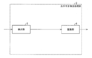
- the manual removal processing unit 2 includes a detection unit 5 and a replacement unit 6.
- the detection unit 5 represents a touched region representing a region where a hand is put in order to perform pen input on a touch panel 7 having a plurality of capacitances arranged in a matrix, and a capacitance signal representing a change in capacitance. Detection is based on the strength and the parameters stored in the hand-held parameter storage unit 8.
- the replacement unit 6 replaces the value of the capacitance signal corresponding to the capacitance arranged in the hand-held area detected by the detection unit 5 with a value indicating no touch input, and the touch recognition unit 4 (FIG. 1).
- the touch recognition unit 4 determines the coordinate value of the pen input based on the capacitance signal replaced with no value by the replacement unit 6 and the capacitance signal corresponding to the capacitance arranged outside the touched area. Is output to the host device 13 connected to the outside of the touch sensor system 1. The host device 13 executes processing by application software based on the coordinate value of the pen input supplied from the touch recognition unit 4.
- the electrostatic capacitance value distribution detection circuit 18 has a timing generator 11.
- the timing generator 11 generates a signal that defines the operation of the driver 9, a signal that defines the operation of the sense amplifier 10, and a signal that defines the operation of the AD converter 12, and the driver 9, the sense amplifier 10, and This is supplied to the AD converter 12.
- FIGS. 3A to 3C are diagrams illustrating a method for detecting a hand area according to the touch sensor system 1.
- FIG. 3A schematically shows a state where characters are being written with the pen 14 while the hand 15 is attached to the touch panel 7 with the touch panel 7 having n drive lines and m sense lines.
- FIG. 3B shows a capacity distribution map in the state shown in FIG. This capacity distribution map is generated by the capacity distribution calculation unit 3 shown in FIG.
- the manual removal processing unit 2 observes the capacitance value (capacitance signal) of each coordinate of the capacitance distribution map, and has a certain fixed value. A region exceeding the threshold “PALM_THRESH” is obtained, and the hand region 16a is extracted. In FIG. 3B, the coordinates (Xp1, Yp1) of the upper left corner and the coordinates (Xp2, Yp2) of the lower right corner of the extracted hand area 16a are obtained to form the first rectangle 16b.
- the replacement area 23 is formed as a second rectangle in which the rectangle 16b is enlarged outward by the parameter PALM_WD stored in the hand-held parameter storage unit 8 (FIG. 1).
- FIG. 3C shows the result of replacing the capacitance value in the replacement area 23 extracted by the manual removal processing unit 2 with zero (hereinafter also referred to as “zero fill”).
- the zero-filled capacity distribution map is transmitted to the touch recognition unit 4 at the subsequent stage. A series of these processes is performed for each frame.
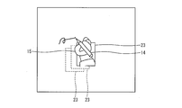
- FIG. 4 is a diagram showing automatic movement of the hand-held area.
- the zero-filled rectangular replacement area 23 in the capacity distribution map input to the touch recognition unit 4 (FIG. 1) automatically moves to the position of the hand.
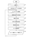
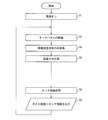
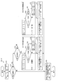
- FIG. 5 is a flowchart showing the operation of the touch sensor system 1.
- the power supply of the touch panel system 1 shown in FIG. 1 is turned on (step S1).
- the parameters stored in the hand-held parameter storage unit 8 provided in the capacitance distribution detection circuit 18 of the touch panel system 1 are initialized (step S2).
- the touch panel 7 is driven by the driver 9 (step S3).
- the capacitance signal read from the touch panel 7 by the sense amplifier 10 is AD converted by the AD converter 12 (step S4).
- the capacitance distribution calculation unit 3 calculates the capacitance distribution of the touch panel 7 based on the capacitance signal AD-converted by the AD converter 12 (step S5).
- the handle removal processing unit 2 calculates a handle region based on the capacity distribution of the touch panel 7 calculated by the capacity distribution calculation unit 3 (step S6). Thereafter, the handle removal processing unit 2 sets a replacement area based on the calculated handle area, and replaces the capacitance value in the replacement area with zero (step S7).
- the touch recognition unit 4 obtains the coordinate value of the pen input based on the capacitance distribution of the touch panel 7 in which the capacitance value in the replacement area is replaced with zero (Step S8). Next, the touch recognition unit 4 outputs the coordinate value of the pen input to the host device 13 (step S9). Then, the process returns to step S3.
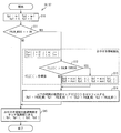
- FIG. 6 is a flowchart showing the operation of the manual removal processing unit 2 provided in the touch sensor system 1. This flowchart corresponds to the detailed flowchart of steps S6 and S7 shown in FIG. 5, and represents the configuration described with reference to FIG.
- m number of sense lines
- n number of drive lines
- PALM_MODE Hand pen mode flag, 1 when on, 0 when off
- PALM_THRESH a threshold value for determining whether or not to handle
- step S12 it is determined whether or not the capacitance value C [j] [i] of the touch panel 7 is larger than the threshold value PALM_THRESH (step S12).
- the minimum value of Xp1 and i is substituted for Xp1, and the minimum value of Yp1 and j is set. Substitute for Yp1.
- the maximum value of Xp2 and i is substituted into Xp2, and the maximum value of Yp2 and j is substituted into Yp2 (step S13). Then, the processes in steps S12 and S13 are repeated for the number of times corresponding to each of the capacitances of n rows and m columns.
- the replacement unit 6 sets the capacitance value C [j] [i] arranged in the replacement region 23 specified by the two points of (Xp1-PALM_WD, Yp1-PALM_WD) and (Xp2 + PALM_WD, Yp2 + PALM_WD) to zero. (Step S14).
- the manual removal processing unit 2 transmits the coordinate information of the replacement area 23 (FIG. 3) to the touch recognition unit 4. (Step S15).
- variable PALM_MODE is a flag indicating whether or not the touch mode is set, and is stored in the touch parameter storage unit 8.
- PALM_MODE When PALM_MODE is on, the handling process shown in steps S12 to S14 described above is executed.
- the algorithm shown in FIG. 6 represents the processing content described with reference to FIG. 3, but this algorithm is designed so that the processing content in the manual removal processing unit 2 can be easily performed.
- the setting of the zero fill area is not necessarily rectangular, and may be an arbitrary shape.
- the setting of the replacement area 23 for the touch recognition unit 4 is not necessarily replaced by zero, and any method may be used as long as the touched area can be set as a non-detection area for touch recognition and represents a state without touch input. Replace with no value.
- the parameter PALM_WD for expanding the hand area 16b is set to the same value for the four directions.
- the present invention is not limited to this, and independent values may be set for the four directions. .
- FIG. 7 is a flowchart showing the operation of the conventional touch sensor system 91 shown in FIG.
- the power supply of the touch panel system 91 is turned on (step S1).
- the touch panel 93 is driven by the driver 95 (step S3).
- the capacitance signal read from the touch panel 93 by the sense amplifier 96 is AD converted by the AD converter 98 (step S4).
- the capacitance distribution calculation unit 99 calculates the capacitance distribution of the touch panel 93 based on the capacitance signal AD-converted by the AD converter 98 (step S5).
- the touch recognition part 90 calculates
- the touch recognition unit 4 outputs the coordinate value of the pen input to the host device (step S9). Then, the process returns to step S3.
- the hand area calculation process (step S6) and the replacement area setting process (step S7) are executed inside the touch sensor system independently of the host device. Configured to do. For this reason, there is no need to embed the display and movement function of the hand-held area by specializing the application software on the host device, and general application software is installed in the host device to remove signals from hands that have arrived at the hand-held region. The pen input signal can be detected without erroneous recognition.
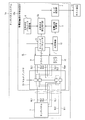
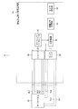
- FIG. 8 is a block diagram illustrating a configuration of the touch sensor system 1a according to the second embodiment.
- the same reference numerals are given to the same components as those described above. Detailed description of these components will not be repeated.
- the touch sensor system 1a includes a touch panel 7 and a capacitance value distribution detection circuit 18a.
- the touch panel 7 includes signal lines HL1 to HLn arranged in parallel to each other in the horizontal direction, signal lines VL1 to VLm arranged in parallel to each other in the vertical direction, signal lines HL1 to HLn, and signal lines VL1 to And a capacitance formed at each intersection with VLm.
- the touch panel 7 preferably has a size that allows the user to wear a hand that holds the input pen, but may be a size used for a smartphone.
- the capacitance value distribution detection circuit 18 a includes a driver 9.
- the driver 9 applies a voltage to the drive lines DL1 to DLn based on the code sequence.
- a sense amplifier 10 is provided in the capacitance value distribution detection circuit 18a. The sense amplifier 10 reads out the linear sum of charges corresponding to the respective capacitances through the sense lines SL1 to SLm, and supplies it to the AD converter 12.
- the capacitance value distribution detection circuit 18 a has a multiplexer 19.
- the multiplexer 19 connects the signal lines HL1 to HLn to the drive lines DL1 to DLn of the driver 9, and connects the signal lines VL1 to VLm to the sense lines SL1 to SLm of the sense amplifier 10, and the signal lines HL1 to HL1.
- the second connection state in which HLn is connected to the sense lines SL1 to SLm of the sense amplifier 10 and the signal lines VL1 to VLm are connected to the drive lines DL1 to DLn of the driver 9 is switched.
- the signal lines HL1 to HLm are connected to the drive lines DL1 to DLn, and the signal lines VL1 to VLm are connected to the sense lines SL1 to SLm.
- the signal lines HL1 to HLn are connected to the sense lines SL1 to SLm, and the signal lines VL1 to VLm are connected to the drive lines DL1 to DLn.
- the AD converter 12 AD converts the linear sum of the charges corresponding to each capacitance read through the sense lines SL1 to SLm, and supplies the result to the capacitance distribution calculation unit 3.
- the capacitance distribution calculation unit 3 calculates a capacitance distribution on the touch panel 3 based on a linear sum of charges corresponding to each capacitance supplied from the AD converter 12 and a code series, and a manual removal processing unit. 2a.
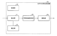
- FIG. 9 is a block diagram showing a configuration of the manual removal processing unit 2a provided in the touch sensor system 1a.
- the manual removal processing unit 2 a includes a detection unit 5.
- the detection unit 5 represents a touched region representing a region where a hand is put in order to perform pen input on a touch panel 7 having a plurality of capacitances arranged in a matrix, and a capacitance signal representing a change in capacitance. Detect based on intensity.
- a replacement area setting unit 20 is provided in the manual removal processing unit 2a.
- the replacement area setting unit 20 sets a replacement area that replaces the value of the capacitance signal with a non-value indicating a state where there is no touch input based on the hand-held area detected by the detection unit 5.
- the replacement area includes a horizontal area extending in the horizontal direction including the hand area and a vertical area extending in the vertical direction including the hand area.
- the replacement area setting unit 20 switches between the horizontal area and the vertical area for each frame in which the capacitance signal is read from the touch panel 7.
- the manual removal processing unit 2a has a replacement unit 6a.
- the replacement unit 6a sets the value of the electrostatic capacity signal corresponding to the electrostatic capacity arranged in the horizontal direction area and the vertical direction area switched by the replacement area setting unit 20 to a non-value indicating a state without touch input. And is supplied to the touch recognition unit 4.
- the storage unit 22 stores parameters used for processing executed by the manual removal processing unit 2a.
- the correction unit 21 will be described later in a third embodiment.
- the touch recognition unit 4 determines the coordinate value of the pen input based on the capacitance signal replaced with no value by the replacement unit 6a and the capacitance signal corresponding to the capacitance arranged outside the touched area. Is output for each frame to the host device 13 connected to the outside of the touch sensor system 1. The host device 13 executes processing by application software based on the coordinate value of the pen input supplied from the touch recognition unit 4.
- the capacitance value distribution detection circuit 18 a has a timing generator 11.
- the timing generator 11 generates a signal that defines the operation of the driver 9, a signal that defines the operation of the sense amplifier 10, and a signal that defines the operation of the AD converter 12, and the driver 9, the sense amplifier 10, and This is supplied to the AD converter 12.
- This system configuration generates phantom noise that represents an erroneous signal generated when electromagnetic noise received from the human body is input to the touch panel through a hand, finger, etc., and superimposed on the signal flowing through the sense line touched by the hand, finger, etc. This is to realize the manual removal process in the case of performing.
- the manual removal processing unit 2a extracts a region having a capacitance value exceeding a certain threshold from the capacitance distribution map according to a method described later, and sets the region as a non-detection region for the touch recognition unit 4. At that time, the parameters stored in the manual parameter storage unit 8 are referred to.
- the touch recognition unit 4 recognizes a touch from the capacity distribution map and sends the touch information to the host device 13.
- the host device 13 executes processing with application software based on the received touch information.
- FIGS. 10A to 10C are diagrams illustrating the principle of the method for detecting the hand-held area according to the touch sensor system 1a.
- FIG. 10A shows the pen shown in FIG. 8 while the hand 15 is attached to the touch panel 7 with the touch panel of n drive lines and m sense lines when the drive line and the sense line are not reversed. 14 schematically shows the writing of characters.
- FIG. 10 (b) shows a capacity distribution map in the state of FIG. 10 (a).
- This capacity distribution map is generated by the capacity distribution calculation unit 3 shown in FIG. Since the phantom noise FM is generated in the direction along the sense line, in order to remove the phantom noise FM, the replacement unit 6a includes the handle area 16b in the vertical direction replacement area 23a extending in the direction along the sense line.
- the value of the electrostatic capacity signal corresponding to the electrostatic capacity disposed in is replaced with a non-value (for example, zero) indicating no touch input (zero fill).
- the manual removal processing unit 2a observes the capacity value of each coordinate of the capacity distribution map and obtains an area exceeding a certain threshold PALM_THRESH. Then, the hand area 16a is extracted.
- PALM_THRESH a certain threshold
- the coordinates (Xp1, Yp1) of the upper left corner and the coordinates (Xp2, Yp2) of the lower right corner of the extracted handle area 16a are obtained to form a handle area 16b that is a first rectangle
- the rectangular hand area 16b is expanded in the Y-axis direction by the parameter PALM_WD stored in the hand-held parameter storage unit 8, and is further replaced in the vertical direction, which is the second rectangle expanded to both ends of the touch panel 7 in the X-axis direction.
- Region 23a is formed.
- FIG. 10 (c) shows the result of replacing the capacitance value in the vertical region 23a, which is the second rectangle extracted by the manual removal processing unit 2a, with zero.
- the replaced capacity distribution map is sent to the touch recognition unit 4 at the subsequent stage. A series of these processes is performed for each frame.
- the phantom noise FM caused by handling is removed by the above processing.
- the touch recognition unit 4 has a pen touch in the vertical area 23a, and recognizes the pen touch. I can't.
- FIGS. 11A to 11C are diagrams showing the principle of the method for detecting the hand-held area according to the touch sensor system 1a.
- FIGS. 11A to 11C show the case where the drive line and the sense line are inverted with respect to FIGS. 10A to 10C.
- FIG. 11A shows a touch panel with m drive lines and n sense lines when the drive lines and the sense lines are reversed in the touch panel system 1a shown in FIG. 7 schematically shows writing a character with a pen 14 while holding a hand 15.
- FIG. 11 (b) shows a capacity distribution map in the state of FIG. 11 (a).
- This capacity distribution map is generated by the capacity distribution calculation unit 3 shown in FIG. Since phantom noise FM is generated in the lateral direction along the sense line, a horizontal region 23b extending in the lateral direction along the sense line is set in order to remove the phantom noise FM.
- the manual removal processing unit 2a observes the capacity value of each coordinate of the capacity distribution map and obtains an area exceeding a certain threshold PALM_THRESH. Then, the hand area 16a is extracted.
- PALM_THRESH a certain threshold
- the coordinates (Xp1, Yp1) of the upper left end and the coordinates (Xp2, Yp2) of the lower right end of the extracted handle area 16a are obtained to form a handle area 16b that is a first rectangle, Then, the rectangular hand area 16b is expanded in the X axis direction by the parameter PALM_WD stored in the hand parameter storage unit 8, and further the horizontal area 23b, which is a second rectangle, is extended to both ends of the touch panel 7 in the Y axis direction. Forming.
- FIG. 11C shows the result of replacing the capacitance value in the horizontal area 23b, which is the second rectangle extracted by the manual removal processing unit 2a, with zero (zero fill).
- the replaced capacity distribution map is sent to the touch recognition unit 4 at the subsequent stage. A series of these processes is performed for each frame.
- 12 (a) to 12 (f), 13 (a) to 13 (f), and 14 (a) to 14 (f) are diagrams showing a method for detecting a hand-held area according to the touch sensor system 1a.
- FIG. 12 (a) there is no inversion of the drive line and the sense line, the vertical area 23a is replaced with zero, and the pen signal area 17a above the hand area 16a cannot be detected.
- FIG. 12B the drive line and the sense line are inverted, the horizontal area 23b is replaced with zero, and the pen signal area 17a located above the hand area 16a can be detected.
- FIG. 12C there is no inversion, the vertical area 23a is replaced with zero, and the pen signal area 17a cannot be detected.
- FIG. 12D there is an inversion, the horizontal area 23b is replaced with zero, and the pen signal area 17a can be detected.
- FIG. 12E there is no inversion, the vertical area 23a is replaced with zero, and the pen signal area 17a cannot be detected. Thereafter, in FIG. 12 (f), there is an inversion, the horizontal area 23b is replaced with zero, and the pen signal area 17a can be detected.
- the pen signal 17a can be detected only when the drive line and the sense line are inverted.
- FIGS. 13A to 13F The operation of FIGS. 13A to 13F will be described.
- FIG. 13A there is no inversion of the drive line and the sense line, the vertical area 23a is replaced with zero, and the pen signal area 17b at the upper left of the hand-held area 16a can be detected.
- FIG. 13B there is an inversion, the horizontal area 23b is replaced with zero, and the pen signal area 17b at the upper left of the hand-held area 16a can be detected.
- FIG. 13C there is no inversion, the vertical direction area 23a is replaced with zero, and the pen signal area 17b can be detected.
- FIG. 13D there is an inversion, the horizontal area 23b is replaced with zero, and the pen signal area 17b can be detected.
- FIG. 13A there is no inversion of the drive line and the sense line, the vertical area 23a is replaced with zero, and the pen signal area 17b at the upper left of the hand-held area 16a can be detected.
- FIG. 13B there is an inversion, the
- FIG. 13E there is no inversion, the vertical direction area 23a is replaced with zero, and the pen signal area 17b can be detected.
- FIG. 13F there is an inversion, the horizontal area 23b is replaced with zero, and the pen signal area 17b can be detected.
- the pen signal 17b can be detected in any case where the drive line and the sense line are inverted.
- FIG. 14A there is no inversion of the drive line and the sense line, the vertical area 23a is replaced with zero, and the pen signal area 17c on the left side of the hand-held area 16a can be detected.
- FIG. 14B the drive line and the sense line are inverted, the horizontal area 23b is replaced with zero, and the pen signal area 17c on the left side of the hand-held area 16a cannot be detected.
- FIG. 14C there is no inversion, the vertical direction area 23a is replaced with zero, and the pen signal area 17c can be detected.
- FIG. 14D there is an inversion, the horizontal area 23b is replaced with zero, and the pen signal area 17c cannot be detected.
- FIG. 14D there is an inversion, the horizontal area 23b is replaced with zero, and the pen signal area 17c cannot be detected.
- the pen signal 17c can be detected only when the drive line and the sense line are not inverted.
- the touch recognition unit 4 in the subsequent stage has at least one of them.
- the pen input signal can be recognized by the frame.
- FIG. 15 is a flowchart showing the operation of the manual removal processing unit 2a provided in the touch sensor system 1a.
- m number of sense lines (value when drive line and sense line are not inverted)
- n number of drive lines (value when drive line and sense line are not inverted)
- PALM_MODE Hand pen mode flag, 1 when on, 0 when off
- PALM_THRESH a threshold value for determining whether or not to handle
- DS_REVERSE Drive sense inversion flag, which is a parameter given from the timing generator, for determining whether to invert the drive line and the sense line, 1 when on, 0 when off, And
- step S16 When it is determined that the variable PALM_MODE is on (Yes in step S11), it is determined whether or not the variable DS_REVERSE is on (step S16). When it is determined that the variable DS_REVERSE is on (Yes in step S16), it is determined whether or not the capacitance value C [j] [i] of the touch panel 7 is larger than the threshold value PALM_THRESH (step S17). When it is determined that the capacitance value C [j] [i] is larger than the threshold value PALM_THRESH (Yes in step S17), the smaller of Xp1 and i is substituted into Xp1, and the larger of Xp2 and i is determined. Substitute into Xp2 (step S18). Then, the processes in steps S17 and S18 are repeated for the number of times corresponding to each of the capacitances of n rows and m columns.
- the replacement unit 6a includes the capacitance value C [j] [i] arranged in the vertical region 23a specified by two points (Xp1-PALM_WD, 0) and (Xp2 + PALM_WD, m ⁇ 1). Is replaced by zero (step S19).
- step S20 it is determined whether or not the capacitance value C [j] [i] of the touch panel 7 is larger than the threshold value PALM_THRESH (step S20).
- the capacitance value C [j] [i] is larger than the threshold value PALM_THRESH (Yes in step S20)
- the smaller of Yp1 and j is substituted for Yp1
- the larger of Yp2 and j is Substitute for Yp2 (step S21). Then, the processes in steps S20 and S21 are repeated for the number of times corresponding to each of the capacitances of n rows and m columns.
- the replacement unit 6a receives the capacitance value C [j] [i] arranged in the horizontal area 23b specified by two points (0, Yp1-PALM_WD) and (n-1, Yp2 + PALM_WD). Is replaced by zero (step S22).
- Step S19 or Step S22 the manual removal processing unit 2a touches the coordinate information of the vertical direction area 23a or the horizontal direction area 23b. It transmits to the recognition part 4 (step S23).
- FIG. 15 is an arrangement of the contents described in FIGS. 10 and 11 in a flowchart.
- the variable PALM_MODE is a flag indicating whether or not the hand-held mode is set, and is stored in the hand-held parameter storage unit 8.
- the handling process shown in steps S16 to S22 described above is executed.
- the algorithm shown in FIG. 15 represents the processing contents described with reference to FIGS. 10 and 11, but this algorithm is designed so that the processing contents in the manual removal processing unit 2a can be easily extracted.
- the hand-held areas 16a and 16b and the vertical and horizontal areas 23a and 23b to be set are not necessarily rectangular but may be of any shape.
- the setting of the vertical direction area 23a and the horizontal direction area 23b for the touch recognition unit 4 is not necessarily replaced with zero, and if the vertical direction area 23a and the horizontal direction area 23b can be set as non-detection areas for touch recognition, Any method may be used. That is, the value may be replaced with a null value representing a state where there is no touch input.
- parameter PALM_WD for expanding the handle area 16b is set to the same value in the two directions, an independent value may be set in each of the two directions.
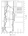
- FIG. 16 is a graph showing a method of correcting the coordinate position of the hand-held area according to the third embodiment. If hysteresis is provided in the detection of the hand-held area, an effect of correcting the boundary line of the detected hand-held area can be obtained.
- the manual removal processing unit 2 extracts the manual area for each frame, and based on the extraction result, the static area in the manual area is extracted.
- the non-detection area was set by replacing the value of the capacitance signal with a non-value indicating a state without touch input.
- a hand-held area is extracted while temporarily storing a capacity distribution map for one frame in a frame memory or the like, and a non-detection area is read out when the stored capacity distribution map is read and sent to the touch recognition unit 4. Processing such as setting is required.
- the frame memory is not used. It is possible to avoid cost increase.
- the extracted hand area of the previous frame will fluctuate greatly if the hand position moves or the contact area between the hand and the touch panel changes. Can be considered. Then, a touch occurs outside the non-detection area (based on the touch state of the previous frame) set in the next frame, and there is a risk that the touch is erroneously recognized as an effective touch. In order to avoid this misrecognition, it is effective to refer to the past extraction result of the region before the previous frame and to provide hysteresis.
- the horizontal axis indicates the frame number
- the vertical axis indicates the sense line number of the touch panel.
- the line C1 shows the plot result for each frame of Yp1 before correction
- the line C2 shows the plot result for each frame of Yp2 before correction
- a line C3 indicates the plotted result for each frame of Yp1 after correction
- a line C4 indicates the plotted result for each frame of Yp2 after correction.
- the magnitude of the maximum value of the previous section and the sense line number of the current frame is judged, and the larger value is used as a correction value and a new maximum value to be referred to.
- the maximum value 34 of the previous frame is compared with the current value 34, and 34 is set as a corrected value and a new maximum value.
- the range H1 is a range from Yp1 to Yp2 before correction
- the range H2 is a range from Yp1 to Yp2 after correction.
- the range from Yp1 to Yp2 is expanded by the correction. Note that after the hand that has touched the touch panel is released from the touch panel to eliminate the hand-held state, the final correction value is continued for a certain time (variable PALM_HOLD_FRAME).
- the detection unit 5 determines the position based on the minimum X coordinate Xp1 and the minimum Y coordinate Yp1 among the positions where the value of the capacitance signal exceeds the threshold value, and the maximum X coordinate Xp2 and the maximum Y coordinate.
- a touch area is detected for each frame in which the capacitance signal is read from the touch panel 7.
- the correction unit 21 provided in the manual removal processing unit 2a corrects the maximum Y coordinate Yp2 for each frame based on the maximum value before one section, and sets the minimum Y coordinate Yp1 based on the minimum value before one section. Correct for each frame.
- FIG. 17 is a flowchart illustrating a method of switching the number of continuous touches for finalizing touch detection according to the fourth embodiment. This flowchart shows an algorithm for dynamically changing the number of continuous touches until the touch recognition unit 4 determines touch detection.
- Touch recognition processing by the touch recognition unit 4 finds a location with a large capacitance value from the capacitance distribution map and recognizes the touch position.
- touch information generation process by the touch recognition unit 4 touch information to be sent to the host device 13 is generated from the recognition result of the touch position.
- the touch information is determined to have been touched for the first time when the touch is recognized continuously for several frames at the same location, and the touch information is sent to the host device 13.
- a variable called nframe is used as the number of consecutive frames when determining how many frames are consecutive in the same location. The larger the nframe value, the longer the time from when the touch panel 7 is touched until the touch information is sent to the host device 13, and the possibility of erroneous detection due to noise or the like is reduced.
- the pen input and the touched state are distinguished based on the difference between the capacity value when the pen is touched on the touch panel and the capacity value when the hand holding the pen is touched on the touch panel. Separated. However, when touching slowly, the change in the capacitance value becomes gradual, and in the middle of starting touching, the same capacitance value as in the case of pen input may be shown. In such a state, there is a possibility that the hand-held state is erroneously detected as pen input.
- a touch recognition process is executed (step S24). Then, it is determined whether or not a touched state in which the hand holding the pen is touched on the touch panel is detected (for example, determination can be made based on whether or not the coordinate Xp2 of the touched region is 0 (initial value)) (step S25).
- step S25 When it is determined that the touched state is not detected (No in step S25), the value of the variable nframe is set to PALM_NFRAME to increase the value (for example, 100) (step S27). When it is determined that the touched state is detected (Yes in step S25), the value of the variable nframe is set to NFRAME and dynamically changed to take a small value (for example, 3). When step S26 or S27 is executed, a touch information generation process is executed (step S28).
- the present invention is not limited to this.
- the present invention can also be applied to touch sensor systems other than the capacitive type.
- the present invention can be applied to an electromagnetic induction type touch sensor system.
- the handle area may be a shape other than a rectangular shape such as a circle, an ellipse, or a triangle.
- the hand signal is removed even with general application software.
- the pen input signal can be detected without erroneous recognition. Therefore, the manual removal process can be performed by replacing the conventional touch panel system with the touch panel system according to the present invention.
- the touch sensor system according to the present embodiment further includes replacement area setting means for setting a replacement area for replacing the value of the capacitance signal with the non-value based on the hand area detected by the detection means. It is preferable that the hand region and the replacement region have a rectangular shape, and the periphery of the replacement region is formed along the outer periphery of the periphery of the hand region.
- a hand-held region representing a region where a hand is put in order to perform pen input on a touch panel having a plurality of capacitances arranged in a matrix can be automatically set with a simple configuration.
- the touch sensor system further includes replacement area setting means for setting a replacement area for replacing the value of the capacitance signal with the non-value based on the hand area detected by the detection means.
- the replacement area includes a horizontal area extending in a horizontal direction including the handle area and a vertical area extending in a vertical direction including the handle area, and the replacement area setting means includes the capacitance signal. It is preferable to switch between the horizontal direction area and the vertical direction area for each frame for reading from the touch panel.
- the hand-held area can be automatically set while removing phantom noise.
- the hand-held area is rectangular
- the detection means includes a minimum X coordinate Xp1 and a minimum Y among positions where the value of the capacitance signal exceeds a threshold value.
- the touch area is detected for each frame for reading the capacitance signal from the touch panel, and a plurality of consecutive frames are 1 section is comprised
- the said detection means correct
- the hand-held area is rectangular, and the detection means has a minimum X coordinate Xp1 and a minimum among positions where the value of the capacitance signal exceeds a threshold value.
- the hand-held region is detected for each frame from which the capacitance signal is read from the touch panel according to the position based on the Y coordinate Yp1 and the position based on the maximum X coordinate Xp2 and the maximum Y coordinate Yp2, and a plurality of consecutive frames Constitutes one section, and the detection means corrects the maximum X coordinate Xp2 for each frame based on the maximum value one section before, and the minimum X coordinate based on the minimum value one section before It is preferable to correct Xp1 for each frame.
- the pen input recognizing unit switches the number of continuous touches for determining the touch detection according to whether or not the detection unit detects the touched area.
- the present invention can be used for a touch sensor system that detects pen input input to a touch panel having a plurality of capacitances arranged in a matrix.
Landscapes
- Engineering & Computer Science (AREA)
- General Engineering & Computer Science (AREA)
- Theoretical Computer Science (AREA)
- Human Computer Interaction (AREA)
- Physics & Mathematics (AREA)
- General Physics & Mathematics (AREA)
- Position Input By Displaying (AREA)
Abstract
一般のアプリケーションソフトをホスト装置に搭載して、お手付き信号を除去できるタッチセンサシステムを提供する。タッチセンサシステム(1)は、お手付き領域を、静電容量の変化を表す静電容量信号の強度に基づいて検出し、検出されたお手付き領域の中に配置された静電容量に対応する静電容量信号の値を、タッチ入力の無い状態を表す無値に置換するお手付き除去処理部(2)を備える。
Description
本発明は、マトリックス状に配置された複数の静電容量を有するタッチパネルに入力されたペン入力を検出するタッチセンサシステムに関する。
複数の第1信号線と複数の第2信号線との交点にそれぞれ形成される複数の静電容量の値の分布を検出するタッチセンサシステムが特許文献1に開示されている。そして、従来の静電容量値の分布を検出するタッチセンサシステムにおいては、特許文献2に示すように、信号処理により、タッチパネルにタッチしている指及び手の部分の認識を試みていた。
図18は、従来のタッチセンサシステム91の構成を示すブロック図である。タッチセンサシステム91は、タッチパネル93と静電容量値分布検出回路92とを備えている。タッチパネル93は、水平方向に沿って互いに平行に配置されたドライブラインHL1~HLnと、垂直方向に沿って互いに平行に配置されたセンスラインVL1~VLmと、ドライブラインHL1~HLnとセンスラインVL1~VLmとの交点にそれぞれ形成される複数の静電容量とを備えている。
静電容量値分布検出回路92は、ドライバ95を備えている。ドライバ95は、符号系列に基づいてドライブラインHL1~HLnに電圧を印加して各静電容量を駆動する。静電容量値分布検出回路92には、センスアンプ96が設けられている。センスアンプ96は、ドライバ95により駆動された各静電容量に対応する電圧の線形和を、センスラインVL1~VLmを通して読み出して、AD変換器98に供給する。AD変換器98は、センスラインVL1~VLmを通して読み出した各静電容量に対応する電圧の線形和をAD変換して容量分布計算部99に供給する。
容量分布計算部99は、AD変換器98から供給された各静電容量に対応する電圧の線形和と符号系列とに基づいて、タッチパネル93上の静電容量分布を計算してタッチ認識部90に供給する。タッチ認識部90は、容量分布計算部99から供給された静電容量分布に基づいて、タッチパネル93上のタッチされた位置を認識する。
静電容量値分布検出回路92は、タイミングジェネレータ97を有している。タイミングジェネレータ97は、ドライバ95の動作を規定する信号と、センスアンプ96の動作を規定する信号と、AD変換器98の動作を規定する信号とを生成して、ドライバ95、センスアンプ96、及びAD変換器98に供給する。
また、マトリックス状に配置された複数の静電容量を有するタッチパネルにペン入力を行うために手を着いた領域を表すお手付き領域を、タッチセンサシステムに接続されたホスト装置に搭載されたアプリケーションソフトウェアから指定し、お手付き領域を示す枠を描画するとともに、タッチパネルにペン入力を行うために着いた手の移動に追随して、随時お手付き領域の位置を修正する構成も知られている。
しかしながら、上記構成では、マトリックス状に配置された複数の静電容量を有するタッチパネルにペン入力を行うために手を着いた領域を表すお手付き領域を指定し、お手付き領域を示す枠を描画するとともに、タッチパネルにペン入力を行うために着いた手の移動に追随して、随時お手付き領域の位置を修正するためのアプリケーションソフトウェアがホスト装置に搭載されているので、このようなお手付き領域を自動的に設定等する構成を実現するためには、お手付き領域を自動的に設定等するためにホスト装置に搭載するアプリケーションソフトウェアを新規に開発する必要があるという問題がある。
本発明の目的は、ホスト装置上のアプリケーションソフトウェアを特化させてお手付き領域の表示及び移動機能を埋め込む必要がなく、一般のアプリケーションソフトをホスト装置に搭載して、お手付き領域に着いた手による信号を除去し、ペン入力信号を誤認識することなく検知することができるタッチセンサシステムを提供することにある。
上記の課題を解決するために、本発明に係るタッチセンサシステムは、マトリックス状に配置された複数の静電容量を有するタッチパネルにペン入力を行うために手を着いた領域を表すお手付き領域を、前記静電容量の変化を表す静電容量信号の強度に基づいて検出する検出手段と、前記検出手段により検出されたお手付き領域の中に配置された静電容量に対応する静電容量信号の値を、タッチ入力の無い状態を表す無値に置換する置換手段と、前記置換手段により無値に置換された静電容量信号と、前記お手付き領域の外に配置された静電容量に対応する静電容量信号とに基づいて、前記ペン入力の座標値をホスト装置に出力するペン入力認識手段とを備えたことを特徴とする。
この特徴により、マトリックス状に配置された複数の静電容量を有するタッチパネルにペン入力を行うために手を着いた領域を表すお手付き領域を、前記静電容量の変化を表す静電容量信号の強度に基づいて検出し、検出されたお手付き領域の中に配置された静電容量に対応する静電容量信号の値を、タッチ入力の無い状態を表す無値に置換し、置換された静電容量信号と、前記お手付き領域の外に配置された静電容量に対応する静電容量信号とに基づいて、前記ペン入力の座標値をホスト装置に出力することができる。このため、お手付き領域の表示及び移動させるための構成を、ホスト装置とは独立して、タッチセンサシステムの中だけで完結することができる。
この結果、ホスト装置上のアプリケーションソフトウェアを特化させてお手付き領域の表示及び移動機能を埋め込む必要がなくなり、一般のアプリケーションソフトをホスト装置に搭載して、お手付き領域に着いた手による信号を除去し、ペン入力信号を誤認識することなく検知することができるタッチセンサシステムを提供することができる。
本発明に係るタッチセンサシステムは、マトリックス状に配置された複数の静電容量を有するタッチパネルにペン入力を行うために手を着いた領域を表すお手付き領域を、前記静電容量の変化を表す静電容量信号の強度に基づいて検出し、検出されたお手付き領域の中に配置された静電容量に対応する静電容量信号の値を、タッチ入力の無い状態を表す無値に置換し、置換された静電容量信号と、前記お手付き領域の外に配置された静電容量に対応する静電容量信号とに基づいて、前記ペン入力に基づく静電容量の変化の分布を算出し、算出された静電容量の変化の分布に基づいて、前記ペン入力の座標値をホスト装置に出力することができる。
このため、お手付き領域の表示及び移動させるための構成を、ホスト装置とは独立して、タッチセンサシステムの中だけで完結することができる。この結果、ホスト装置上のアプリケーションソフトウェアを特化させてお手付き領域の表示及び移動機能を埋め込む必要がなくなり、一般のアプリケーションソフトをホスト装置に搭載して、お手付き領域に着いた手による信号を除去し、ペン入力信号を誤認識することなく検知することができるタッチセンサシステムを提供することができる。
以下、本発明に係る実施の形態のタッチセンサシステムについて、詳細に説明する。
(実施の形態1)
(タッチセンサシステム1の構成)
図1は、実施の形態1に係るタッチセンサシステム1の構成を示すブロック図である。タッチセンサシステム1は、タッチパネル7と静電容量値分布検出回路18とを備えている。タッチパネル7は、水平方向に沿って互いに平行に配置されたドライブラインHL1~HLnと、垂直方向に沿って互いに平行に配置されたセンスラインVL1~VLmと、ドライブラインHL1~HLnとセンスラインVL1~VLmとの交点にそれぞれ形成される複数の静電容量とを備えている。
(タッチセンサシステム1の構成)
図1は、実施の形態1に係るタッチセンサシステム1の構成を示すブロック図である。タッチセンサシステム1は、タッチパネル7と静電容量値分布検出回路18とを備えている。タッチパネル7は、水平方向に沿って互いに平行に配置されたドライブラインHL1~HLnと、垂直方向に沿って互いに平行に配置されたセンスラインVL1~VLmと、ドライブラインHL1~HLnとセンスラインVL1~VLmとの交点にそれぞれ形成される複数の静電容量とを備えている。
静電容量値分布検出回路18は、ドライバ9を備えている。ドライバ9は、符号系列に基づいてドライブラインHL1~HLnに電圧を印加して各静電容量を駆動する。静電容量値分布検出回路18には、センスアンプ10が設けられている。センスアンプ10は、ドライバ9により駆動された各静電容量に対応する電圧の線形和を、センスラインVL1~VLmを通して読み出して、AD変換器12に供給する。AD変換器12は、センスラインVL1~VLmを通して読み出した各静電容量に対応する電圧の線形和をAD変換して容量分布計算部3に供給する。
容量分布計算部3は、AD変換器12から供給された各静電容量に対応する電圧の線形和と符号系列とに基づいて、タッチパネル7上の静電容量分布を計算してお手付き除去処理部2に供給する。
図2は、タッチセンサシステム1に設けられたお手付き除去処理部2の構成を示すブロック図である。お手付き除去処理部2は、検出部5と置換部6とを有している。検出部5は、マトリックス状に配置された複数の静電容量を有するタッチパネル7にペン入力を行うために手を着いた領域を表すお手付き領域を、静電容量の変化を表す静電容量信号の強度、及びお手付きパラメータ記憶部8に記憶されたパラメータに基づいて検出する。置換部6は、検出部5により検出されたお手付き領域の中に配置された静電容量に対応する静電容量信号の値を、タッチ入力の無い状態を表す無値に置換してタッチ認識部4(図1)に供給する。
タッチ認識部4は、置換部6により無値に置換された静電容量信号と、お手付き領域の外に配置された静電容量に対応する静電容量信号とに基づいて、ペン入力の座標値を、タッチセンサシステム1の外部に接続されたホスト装置13に出力する。ホスト装置13は、タッチ認識部4から供給されたペン入力の座標値に基づいて、アプリケーションソフトでの処理を実行する。
静電容量値分布検出回路18は、タイミングジェネレータ11を有している。タイミングジェネレータ11は、ドライバ9の動作を規定する信号と、センスアンプ10の動作を規定する信号と、AD変換器12の動作を規定する信号とを生成して、ドライバ9、センスアンプ10、及びAD変換器12に供給する。
(お手付き領域の検知方法)
図3(a)~(c)は、タッチセンサシステム1に係るお手付き領域の検知方法を示す図である。図3(a)は、ドライブラインn本、センスラインm本のタッチパネル7で手15をタッチパネル7に付きしながらペン14で字を書いている様子を模式的に示している。図3(b)は、図3(a)に示す状態での容量分布マップを示す。この容量分布マップは図1に示す容量分布計算部3にて生成される。
図3(a)~(c)は、タッチセンサシステム1に係るお手付き領域の検知方法を示す図である。図3(a)は、ドライブラインn本、センスラインm本のタッチパネル7で手15をタッチパネル7に付きしながらペン14で字を書いている様子を模式的に示している。図3(b)は、図3(a)に示す状態での容量分布マップを示す。この容量分布マップは図1に示す容量分布計算部3にて生成される。
実施の形態1では、容量分布計算部3にて容量分布マップを作成する際に、お手付き除去処理部2が容量分布マップの各座標の容量値(静電容量信号)を観測し、ある一定の閾値「PALM_THRESH」を超える領域を求め、お手付き領域16aを抽出する。図3(b)では、抽出されたお手付き領域16aの左上端の座標(Xp1、Yp1)と右下端の座標(Xp2、Yp2)を求めて第一の矩形16bを形成し、さらに、その第一の矩形16bをお手付きパラメータ記憶部8(図1)に記憶されたパラメータPALM_WDだけ外側に大きくした第二の矩形である置換領域23を形成する。
図3(c)は、お手付き除去処理部2にて抽出された置換領域23内の容量値をゼロで置き換え(以下、「ゼロフィル」とも表記する)た結果を示す。そのゼロフィルされた容量分布マップを後段のタッチ認識部4に送信する。これらの一連の処理は、フレームごとに行われる。
図4は、お手付き領域の自動移動を示す図である。ペン14を把持してお手付きする手15の位置の移動に従って、タッチ認識部4(図1)に入力される容量分布マップにおけるゼロフィルされた矩形の置換領域23は、お手付き位置の移動に自動的に追随する。
(タッチセンサシステム1の動作)
図5は、タッチセンサシステム1の動作を示すフローチャートである。まず、図1に示すタッチパネルシステム1の電源をオンする(ステップS1)。そして、タッチパネルシステム1の静電容量分布検出回路18に設けられたお手付きパラメータ記憶部8に格納されたパラメータを初期化する(ステップS2)。次に、ドライバ9によりタッチパネル7を駆動する(ステップS3)。その後、センスアンプ10によりタッチパネル7から読み出した静電容量信号をAD変換器12によりAD変換する(ステップS4)。
図5は、タッチセンサシステム1の動作を示すフローチャートである。まず、図1に示すタッチパネルシステム1の電源をオンする(ステップS1)。そして、タッチパネルシステム1の静電容量分布検出回路18に設けられたお手付きパラメータ記憶部8に格納されたパラメータを初期化する(ステップS2)。次に、ドライバ9によりタッチパネル7を駆動する(ステップS3)。その後、センスアンプ10によりタッチパネル7から読み出した静電容量信号をAD変換器12によりAD変換する(ステップS4)。
そして、容量分布計算部3は、AD変換器12によりAD変換された静電容量信号に基づいて、タッチパネル7の容量分布を計算する(ステップS5)。次に、お手付き除去処理部2は、容量分布計算部3により計算されたタッチパネル7の容量分布に基づいて、お手付き領域を算出する(ステップS6)。その後、お手付き除去処理部2は、算出したお手付き領域に基づいて置換領域を設定し、置換領域内の容量値をゼロで置き換える(ステップS7)。
そして、タッチ認識部4は、置換領域内の容量値をゼロで置き換えたタッチパネル7の容量分布に基づいて、ペン入力の座標値を求める(ステップS8)。次に、タッチ認識部4は、ペン入力の座標値をホスト装置13に出力する(ステップS9)。そして、ステップS3に戻る。
図6は、タッチセンサシステム1に設けられたお手付き除去処理部2の動作を示すフローチャートである。このフローチャートは、図5に示すステップS6及びS7の詳細なフローチャートに相当し、図3で説明した構成をフローチャートにより表現したものである。
ここで、
m:センスライン数、
n:ドライブライン数、
PALM_MODE:お手付きペンモードフラグ、オンのとき1、オフのときは0、
PALM_THRESH:お手付きか否かを判断するためのしきい値、
とする。
m:センスライン数、
n:ドライブライン数、
PALM_MODE:お手付きペンモードフラグ、オンのとき1、オフのときは0、
PALM_THRESH:お手付きか否かを判断するためのしきい値、
とする。
まず、お手付き除去処理部2に設けられた検出部5は、お手付きパラメータ記憶部8に記憶された座標値を、Xp1=n-1、Yp1=m-1、Xp2=0、Yp2=0に初期化する(ステップS10)。そして、検出部5は、変数PALM_MODEがオンであるか否かを判定する(ステップS11)。
変数PALM_MODEがオンであると判定したときは(ステップS11でYes)、タッチパネル7の容量値C[j][i]がしきい値PALM_THRESHよりも大きいか否かを判定する(ステップS12)。容量値C[j][i]がしきい値PALM_THRESHよりも大きいと判定したときは(ステップS12でYES)、Xp1とiとの最小値をXp1に代入し、Yp1とjとの最小値をYp1に代入する。次に、Xp2とiとの最大値をXp2に代入し、Yp2とjとの最大値をYp2に代入する(ステップS13)。そして、このステップS12及びS13の処理を、n行m列の静電容量のそれぞれに対応するだけの回数分繰り返す。
その後、置換部6は、(Xp1-PALM_WD、Yp1-PALM_WD)、及び(Xp2+PALM_WD、Yp2+PALM_WD)の2点により特定される置換領域23の中に配置された容量値C[j][i]をゼロにより置換する(ステップS14)。
変数PALM_MODEがオンでないと判定したときは(ステップS11でNo)、またはステップS14を実行したときは、お手付き除去処理部2は、置換領域23(図3)の座標情報をタッチ認識部4に送信する(ステップS15)。
変数PALM_MODEは、お手付きモードかどうかを示すフラグであり、お手付きパラメータ記憶部8に記憶されている。PALM_MODEがオンの場合、上述したステップS12~S14に示すお手付き対応処理が実行される。
図6に示すアルゴリズムは、図3で説明した処理内容を表すものであるが、このアルゴリズムは、お手付き除去処理部2での処理内容が簡単にできるようにしたものであり、お手付き領域の抽出、および、ゼロフィル領域の設定は矩形である必然性はなく、任意の形状でもよい。
また、タッチ認識部4に対する置換領域23の設定もゼロにより置換する必然性はなく、お手付き領域をタッチ認識の非検知領域に設定できるのであれば、任意の方法でよく、タッチ入力の無い状態を表す無値で置換すればよい。
また、お手つき領域16bを拡張するためのパラメータPALM_WDは、4方向に対して同じ値を設定しているが、本発明はこれに限定されず、4方向にそれぞれ独立な値を設定してもよい。
図7は、図18に示す従来のタッチセンサシステム91の動作を示すフローチャートである。まず、タッチパネルシステム91の電源をオンする(ステップS1)。そして、ドライバ95によりタッチパネル93を駆動する(ステップS3)。その後、センスアンプ96によりタッチパネル93から読み出した静電容量信号をAD変換器98によりAD変換する(ステップS4)。
そして、容量分布計算部99は、AD変換器98によりAD変換された静電容量信号に基づいて、タッチパネル93の容量分布を計算する(ステップS5)。
そして、タッチ認識部90は、タッチパネル93の容量分布に基づいて、ペン入力の座標値を求める(ステップS8)。次に、タッチ認識部4は、ペン入力の座標値をホスト装置に出力する(ステップS9)。そして、ステップS3に戻る。
このように、実施の形態1に係るタッチセンサシステムでは、お手付き領域の算出処理(ステップS6)及び置換領域の設定処理(ステップS7)を、ホスト装置とは独立してタッチセンサシステムの内部で実行するように構成した。このため、ホスト装置上のアプリケーションソフトウェアを特化させてお手付き領域の表示及び移動機能を埋め込む必要がなくなり、一般のアプリケーションソフトをホスト装置に搭載して、お手付き領域に着いた手による信号を除去し、ペン入力信号を誤認識することなく検知することができる。
(実施の形態2)
(タッチセンサシステム1aの構成)
図8は、実施の形態2に係るタッチセンサシステム1aの構成を示すブロック図である。前述した構成要素と同一の構成要素には同一の参照符号を付している。これらの構成要素の詳細な説明は繰り返さない。
(タッチセンサシステム1aの構成)
図8は、実施の形態2に係るタッチセンサシステム1aの構成を示すブロック図である。前述した構成要素と同一の構成要素には同一の参照符号を付している。これらの構成要素の詳細な説明は繰り返さない。
タッチセンサシステム1aは、タッチパネル7と静電容量値分布検出回路18aとを備えている。タッチパネル7は、水平方向に沿って互いに平行に配置された信号線HL1~HLnと、垂直方向に沿って互いに平行に配置された信号線VL1~VLmと、信号線HL1~HLnと信号線VL1~VLmとの交点にそれぞれ形成される静電容量とを備えている。タッチパネル7は、入力用ペンを把持した手を着くことができる広さを有していることが好ましいが、スマートフォンに使用される大きさであってもよい。
静電容量値分布検出回路18aは、ドライバ9を備えている。ドライバ9は、符号系列に基づいてドライブラインDL1~DLnに電圧を印加する。静電容量値分布検出回路18aには、センスアンプ10が設けられている。センスアンプ10は、各静電容量に対応する電荷の線形和を、センスラインSL1~SLmを通して読み出して、AD変換器12に供給する。
静電容量値分布検出回路18aは、マルチプレクサ19を有している。マルチプレクサ19は、信号線HL1~HLnをドライバ9のドライブラインDL1~DLnに接続し、信号線VL1~VLmをセンスアンプ10のセンスラインSL1~SLmに接続する第1接続状態と、信号線HL1~HLnをセンスアンプ10のセンスラインSL1~SLmに接続し、信号線VL1~VLmをドライバ9のドライブラインDL1~DLnに接続する第2接続状態とを切替える。
制御線CLの信号をLowにすると、信号線HL1~HLmは、ドライブラインDL1~DLnにつながり、信号線VL1~VLmは、センスラインSL1~SLmにつながる。制御線CLの信号をHighにすると、信号線HL1~HLnは、センスラインSL1~SLmにつながり、信号線VL1~VLmは、ドライブラインDL1~DLnにつながる。
AD変換器12は、センスラインSL1~SLmを通して読み出した各静電容量に対応する電荷の線形和をAD変換して容量分布計算部3に供給する。
容量分布計算部3は、AD変換器12から供給された各静電容量に対応する電荷の線形和と符号系列とに基づいて、タッチパネル3上の静電容量分布を計算してお手付き除去処理部2aに供給する。
図9は、タッチセンサシステム1aに設けられたお手付き除去処理部2aの構成を示すブロック図である。お手付き除去処理部2aは、検出部5を有している。検出部5は、マトリックス状に配置された複数の静電容量を有するタッチパネル7にペン入力を行うために手を着いた領域を表すお手付き領域を、静電容量の変化を表す静電容量信号の強度に基づいて検出する。
お手付き除去処理部2aには、置換領域設定部20が設けられている。置換領域設定部20は、検出部5により検出されたお手付き領域に基づいて、静電容量信号の値を、タッチ入力の無い状態を表す無値に置換する置換領域を設定する。
置換領域は、お手付き領域を含んで水平方向に伸びる水平方向領域と、お手付き領域を含んで垂直方向に伸びる垂直方向領域とを含んでいる。置換領域設定部20は、静電容量信号をタッチパネル7から読み出すフレームごとに、水平方向領域と垂直方向領域とを切り替える。
お手付き除去処理部2aは、置換部6aを有している。置換部6aは、置換領域設定部20により切り替えられた水平方向領域、垂直方向領域の中に配置された静電容量に対応する静電容量信号の値を、タッチ入力の無い状態を表す無値に置換して、タッチ認識部4に供給する。記憶部22には、お手付き除去処理部2aにより実行される処理に使用されるパラメータが格納される。補正部21については、実施の形態3で後述する。
タッチ認識部4は、置換部6aにより無値に置換された静電容量信号と、お手付き領域の外に配置された静電容量に対応する静電容量信号とに基づいて、ペン入力の座標値を、タッチセンサシステム1の外部に接続されたホスト装置13にフレームごとに出力する。ホスト装置13は、タッチ認識部4から供給されたペン入力の座標値に基づいて、アプリケーションソフトでの処理を実行する。
静電容量値分布検出回路18aは、タイミングジェネレータ11を有している。タイミングジェネレータ11は、ドライバ9の動作を規定する信号と、センスアンプ10の動作を規定する信号と、AD変換器12の動作を規定する信号とを生成して、ドライバ9、センスアンプ10、及びAD変換器12に供給する。
このシステム構成は、人体が空間から受けた電磁ノイズが、手、指等を通じてタッチパネルに入力され、手、指等がタッチしたセンスラインを流れる信号に重畳されて生じる誤信号を表すファントムノイズが発生する場合のお手付き除去処理を実現するためのものである。
お手付き除去処理部2aは、後述する方式に従って、容量分布マップから一定の閾値を超える容量値を持つ領域を抽出し、その領域をタッチ認識部4に対する非検知領域として設定する。その際、お手付きパラメータ記憶部8に記憶されたパラメータを参照する。
タッチ認識部4は、容量分布マップからタッチを認識し、タッチ情報をホスト装置13に対して送出する。ホスト装置13は、受け取ったタッチ情報に基づいて、アプリケーションソフトでの処理を実行する。
(タッチセンサシステム1aに係るお手付き領域の検知方法)
図10(a)~(c)は、タッチセンサシステム1aに係るお手付き領域の検知方法の原理を示す図である。図10(a)は、図8に示すシステムにて、ドライブラインとセンスラインとの反転を行わない場合に、ドライブラインn本、センスラインm本のタッチパネルで手15をタッチパネル7に付きながらペン14で字を書いている様子を模式的に示している。
図10(a)~(c)は、タッチセンサシステム1aに係るお手付き領域の検知方法の原理を示す図である。図10(a)は、図8に示すシステムにて、ドライブラインとセンスラインとの反転を行わない場合に、ドライブラインn本、センスラインm本のタッチパネルで手15をタッチパネル7に付きながらペン14で字を書いている様子を模式的に示している。
図10(b)は、図10(a)の状態での容量分布マップを示す。この容量分布マップは図8に示す容量分布計算部3にて生成される。センスラインに沿った方向にファントムノイズFMが発生するので、ファントムノイズFMを除去するために、置換部6aは、お手付き領域16bを含んでセンスラインに沿った方向に伸びる垂直方向置換領域23aの中に配置された静電容量に対応する静電容量信号の値を、タッチ入力の無い状態を表す無値(例えばゼロ)に置換する(ゼロフィル)。
実施の形態2では、容量分布計算部3にて容量分布マップを作成する際に、お手付き除去処理部2aが容量分布マップの各座標の容量値を観測し、一定の閾値PALM_THRESHを超える領域を求め、お手付き領域16aを抽出する。図10(b)では、抽出されたお手付き領域16aの左上端の座標(Xp1,Yp1)と右下端の座標(Xp2,Yp2)を求めて第一の矩形であるお手付き領域16bを形成し、さらに、その矩形のお手付き領域16bを、お手付きパラメータ記憶部8に記憶されたパラメータPALM_WDだけY軸方向に拡張し、さらにX軸方向にはタッチパネル7の両端まで拡張した第二の矩形である垂直方向置換領域23aを形成する。
図10(c)は、お手付き除去処理部2aにて抽出された第二の矩形である垂直方向領域23aの中の静電容量値をゼロで置換した結果を示す。その置換された容量分布マップを後段のタッチ認識部4に送る。これらの一連の処理は、フレームごとに行われる。
上記の処理により、お手付きに起因するファントムノイズFMは除去される。しかし、図10(a)に示すようにゼロで置換される領域にペン14で字を書こうとしてもタッチ認識部4では、垂直方向領域23a内にペンタッチがあることになり、ペンタッチを認識することができない。
なお、タッチパネル7のドライブラインとセンスラインとを反転しているか否かの情報は、タイミングジェネレータ11からお手付き除去処理部2aに伝えられる。
図11(a)~(c)は、タッチセンサシステム1aに係るお手付き領域の検知方法の原理を示す図である。図10(a)~(c)に対して、ドライブラインとセンスラインとの反転を行った場合を図11(a)~(c)に示す。
図11(a)は、図8に示すタッチパネルシステム1aにてドライブラインとセンスラインとの反転を行った場合に、ドライブラインとセンスラインとを入れ替え、ドライブラインm本、センスラインn本のタッチパネル7に手15を付きながらペン14で字を書いている様子を模式的に示している。
図11(b)は、図11(a)の状態での容量分布マップを示す。この容量分布マップは図8に示す容量分布計算部3にて生成される。センスラインに沿った横方向にファントムノイズFMが発生するので、ファントムノイズFMを除去するためにセンスラインに沿った横方向に伸びる水平方向領域23bを設定する。
実施の形態2では、容量分布計算部3にて容量分布マップを作成する際に、お手付き除去処理部2aが容量分布マップの各座標の容量値を観測し、一定の閾値PALM_THRESHを超える領域を求め、お手付き領域16aを抽出する。図11(b)では、抽出されたお手付き領域16aの左上端の座標(Xp1,Yp1)と右下端の座標(Xp2,Yp2)を求めて第一の矩形であるお手付き領域16bを形成し、さらに、その矩形のお手付き領域16bをお手付きパラメータ記憶部8に記憶されたパラメータPALM_WDだけX軸方向に拡張し、さらにY軸方向にタッチパネル7の両端まで拡張した第二の矩形である水平方向領域23bを形成している。
図11(c)は、お手付き除去処理部2aにて抽出された第二の矩形である水平方向領域23b内の容量値をゼロで置き換えた(ゼロフィル)結果を示している。その置換された容量分布マップを後段のタッチ認識部4に送る。これらの一連の処理は、フレームごとに行われる。
上記の処理により、お手付きに起因するファントムノイズFMは除去され、図11(a)のようにゼロで置換される領域の外にペンの信号があるため、タッチ認識部4でペンタッチの検出が可能である。
なお、タッチパネルのドライブラインとセンスラインとの反転を行っているか否かの情報は、タイミングジェネレータ11からお手付き除去処理部2aに伝えられる。
図12(a)~(f)、図13(a)~(f)、及び図14(a)~(f)は、タッチセンサシステム1aに係るお手付き領域の検知方法を示す図である。
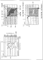
図12(a)では、ドライブラインとセンスラインとの反転が無く、垂直方向領域23aがゼロで置換されており、お手付き領域16aの上側にあるペン信号領域17aを検知することができない。次に、図12(b)では、ドライブラインとセンスラインとが反転し、水平方向領域23bがゼロで置換され、お手付き領域16aの上側にあるペン信号領域17aを検知することができる。そして、図12(c)では、反転が無く、垂直方向領域23aがゼロで置換され、ペン信号領域17aを検知することができない。その後、図12(d)では、反転があり、水平方向領域23bがゼロで置換され、ペン信号領域17aを検知することができる。
次に、図12(e)では、反転が無く、垂直方向領域23aがゼロで置換され、ペン信号領域17aを検知することができない。その後、図12(f)では、反転があり、水平方向領域23bがゼロで置換され、ペン信号領域17aを検知することができる。
このように、図12(a)~(f)に示す動作では、ドライブラインとセンスラインとを反転させたときのみ、ペン信号17aを検知することができる。
図13(a)~(f)の動作を説明する。図13(a)では、ドライブラインとセンスラインとの反転が無く、垂直方向領域23aがゼロで置換されており、お手付き領域16aの左上にあるペン信号領域17bを検知することができる。そして、図13(b)では、反転があり、水平方向領域23bがゼロで置換され、お手付き領域16aの左上にあるペン信号領域17bを検知することができる。次に、図13(c)では、反転が無く、垂直方向領域23aがゼロで置換され、ペン信号領域17bを検知することができる。その後、図13(d)では、反転があり、水平方向領域23bがゼロで置換され、ペン信号領域17bを検知することができる。そして、図13(e)では、反転が無く、垂直方向領域23aがゼロで置換され、ペン信号領域17bを検知することができる。次に、図13(f)では、反転があり、水平方向領域23bがゼロで置換され、ペン信号領域17bを検知することができる。
このように、図13(a)~(f)に示す動作では、ドライブラインとセンスラインとの反転あり、なしのいずれの場合もペン信号17bを検知することができる。
図14(a)~(f)の動作を説明する。まず、図14(a)では、ドライブラインとセンスラインとの反転が無く、垂直方向領域23aがゼロで置換されており、お手付き領域16aの左側にあるペン信号領域17cを検知することができる。そして、図14(b)では、ドライブラインとセンスラインとが反転し、水平方向領域23bがゼロで置換され、お手付き領域16aの左側にあるペン信号領域17cを検知することができない。次に、図14(c)では、反転が無く、垂直方向領域23aがゼロで置換され、ペン信号領域17cを検知することができる。その後、図14(d)では、反転があり、水平方向領域23bがゼロで置換され、ペン信号領域17cを検知することができない。そして、図14(e)では、反転が無く、垂直方向領域23aがゼロで置換され、ペン信号領域17cを検知することができる。次に、図14(f)では、反転があり、水平方向領域23bがゼロで置換され、ペン信号領域17cを検知することができない。
このように、図14(a)~(f)に示す動作では、ドライブラインとセンスラインとの反転が無いときのみ、ペン信号17cを検知することができる。
以上のように、フレームごとに、ドライブラインとセンスラインを入れ替えて、置換領域の方向を、垂直方向領域23aと水平方向領域23bとで切り替えることにより、後段のタッチ認識部4では、少なくとも一方のフレームでペン入力信号を認識することが可能になる。
(タッチセンサシステム1aの動作)
図15は、タッチセンサシステム1aに設けられたお手付き除去処理部2aの動作を示すフローチャートである。
図15は、タッチセンサシステム1aに設けられたお手付き除去処理部2aの動作を示すフローチャートである。
ここで、
m:センスライン数(ドライブラインとセンスラインとを反転しないときの値)、
n:ドライブライン数(ドライブラインとセンスラインとを反転しないときの値)、
PALM_MODE:お手付きペンモードフラグ、オンのとき1、オフのときは0、
PALM_THRESH:お手付きか否かを判断するためのしきい値、
DS_REVERSE:ドライブラインとセンスラインとを反転させるか否かの判断のために、タイミングジェネレータから与えられるパラメータであるドライブセンス反転フラグ、オンのとき1、オフのときは0、
とする。
m:センスライン数(ドライブラインとセンスラインとを反転しないときの値)、
n:ドライブライン数(ドライブラインとセンスラインとを反転しないときの値)、
PALM_MODE:お手付きペンモードフラグ、オンのとき1、オフのときは0、
PALM_THRESH:お手付きか否かを判断するためのしきい値、
DS_REVERSE:ドライブラインとセンスラインとを反転させるか否かの判断のために、タイミングジェネレータから与えられるパラメータであるドライブセンス反転フラグ、オンのとき1、オフのときは0、
とする。
まず、お手付き除去処理部2aに設けられた検出部5は、お手付きパラメータ記憶部8に記憶された座標値を、Xp1=n-1、Yp1=m-1、Xp2=0、Yp2=0に初期化する(ステップS10)。そして、検出部5は、変数PALM_MODEがオンであるか否かを判定する(ステップS11)。
変数PALM_MODEがオンであると判定したときは(ステップS11でYes)、変数DS_REVERSEがオンであるか否かを判定する(ステップS16)。変数DS_REVERSEがオンであると判定したときは(ステップS16でYes)、タッチパネル7の容量値C[j][i]がしきい値PALM_THRESHよりも大きいか否かを判定する(ステップS17)。容量値C[j][i]がしきい値PALM_THRESHよりも大きいと判定したときは(ステップS17でYes)、Xp1とiとの小さい方をXp1に代入し、Xp2とiとの大きい方をXp2に代入する(ステップS18)。そして、このステップS17及びS18の処理を、n行m列の静電容量のそれぞれに対応するだけの回数分繰り返す。
次に、置換部6aは、(Xp1-PALM_WD、0)、及び(Xp2+PALM_WD、m-1)の2点により特定される垂直方向領域23aの中に配置された容量値C[j][i]をゼロにより置換する(ステップS19)。
変数DS_REVERSEがオンでないと判定したときは(ステップS16でNo)、タッチパネル7の容量値C[j][i]がしきい値PALM_THRESHよりも大きいか否かを判定する(ステップS20)。容量値C[j][i]がしきい値PALM_THRESHよりも大きいと判定したときは(ステップS20でYes)、Yp1とjとの小さい方をYp1に代入し、Yp2とjとの大きい方をYp2に代入する(ステップS21)。そして、このステップS20及びS21の処理を、n行m列の静電容量のそれぞれに対応するだけの回数分繰り返す。
次に、置換部6aは、(0、Yp1-PALM_WD)、及び(n-1、Yp2+PALM_WD)の2点により特定される水平方向領域23bの中に配置された容量値C[j][i]をゼロにより置換する(ステップS22)。
変数PALM_MODEがオンでないと判定したとき(ステップS11でNo)、ステップS19,またはステップS22を実行したときは、お手付き除去処理部2aは、垂直方向領域23a、または水平方向領域23bの座標情報をタッチ認識部4に送信する(ステップS23)。
図15は、図10、図11で説明した内容をフローチャートに整理したものである。変数PALM_MODEは、お手付きモードか否かを示すフラグであり、お手付きパラメータ記憶部8に記憶されている。変数PALM_MODEがオンの場合、上述したステップS16~S22に示すお手付き対応処理が実行される。
図15に示すアルゴリズムは、図10、図11で説明した処理内容を表すものであるが、このアルゴリズムは、お手付き除去処理部2aでの処理内容が簡単にできるようにしたものであり、抽出するお手付き領域16a・16b、および、設定する垂直方向領域23a・水平方向領域23bは矩形である必然性はなく、任意の形状でも構わない。
また、タッチ認識部4に対する垂直方向領域23a、水平方向領域23bの設定もゼロで置換する必然性はなく、垂直方向領域23a、水平方向領域23bをタッチ認識の非検知領域に設定できるのであれば、任意の方法でよい。つまり、タッチ入力の無い状態を表す無値で置換すればよい。
また、お手つき領域16bを拡張するためのパラメータPALM_WDは、2方向に対して同じ値を設定しているが、2方向にそれぞれ独立な値を設定してもよい。
(実施の形態3)
(お手付き領域の座標位置の補正方法)
図16は、実施の形態3に係るお手付き領域の座標位置の補正方法を示すグラフである。お手付き領域の検出にヒステリシスを持たせると、検出したお手付き領域の境界線を補正する効果を得ることができる。
(お手付き領域の座標位置の補正方法)
図16は、実施の形態3に係るお手付き領域の座標位置の補正方法を示すグラフである。お手付き領域の検出にヒステリシスを持たせると、検出したお手付き領域の境界線を補正する効果を得ることができる。
これまでに述べてきた実施の形態1、および、実施の形態2のお手付き除去方式では、フレームごとにお手付き領域をお手付き除去処理部2が抽出し、その抽出結果に基づいて、お手付き領域内の静電容量信号の値を、タッチ入力の無い状態を表す無値に置換して非検知領域を設定していた。
しかしながら、この方式では、一旦、容量分布マップの全体をスキャンし、お手付き領域を抽出した後、改めて容量分布マップの全体に対してタッチ認識部4で非検知領域を設定する必要がある。
そのためには、一旦、1フレーム分の容量分布マップをフレームメモリ等に記憶させながらお手付き領域を抽出し、その記憶された容量分布マップを読み出してタッチ認識部4に送出する際に非検知領域を設定する等の処理が必要になる。
これに対して、あるフレームの容量分布マップに対してお手付き領域を抽出し、その抽出結果に基づいて次のフレームの容量分布マップに対して非検知領域の設定をすれば、フレームメモリを使わずに済み、コストアップを避けることができる。
ただし、前フレームのお手付き領域抽出結果を次のフレームに反映させると、お手付き位置が移動したり、お手付きする手とタッチパネル面との接触面積が変わった場合、抽出されるお手付き領域が大きく変動することが考えられる。そうすると、次フレームで設定される非検知領域(前フレームのお手付き状態に基づく)外にお手付きが発生し、お手付きを有効なタッチであると誤認識するおそれが生じる。この誤認識を避けるためには、前フレーム以前の過去のお手付き領域の抽出結果を参照し、ヒステリシスを持たせる構成が効果的である。
図16を参照すると、横軸はフレーム番号を示し、縦軸はタッチパネルのセンスライン番号を示す。そして、各フレームごとに抽出したお手付き領域の左上の点(Xp1、Yp1)及び右下の点(Xp2,Yp2)に対して、Yp1及びYp2の値をプロットしている。例えば、フレーム番号1の場合は、補正前も補正後もYp1=24、Yp2=30となる。
線C1は、補正前のYp1のフレームごとのプロット結果を示し、線C2は、補正前のYp2のフレームごとのプロット結果を示す。線C3は、補正後のYp1のフレームごとのプロット結果を示し、線C4は、補正後のYp2のフレームごとのプロット結果を示す。
お手付き領域のYp2の補正には、連続するフレームを一定の数の変数FRAME_INTERVALごとの区間に分け、その区間内での最大値を記憶する。たとえば、フレーム番号1のときの補正前Yp2=30、フレーム番号2のときの補正前Yp2=32、フレーム番号3のときの補正前Yp2=33、フレーム番号4のときの補正前Yp2=34、フレーム番号5のときの補正前Yp2=33であるから、フレーム番号1~5の区間の最大値は34になる。
次のフレームでは、前の区間の最大値と、現時点でのフレームのセンスライン番号との大小を判断し、大きい値を補正値とするとともに、参照すべき新たな最大値とする。例えば、フレーム番号6の場合は、前のフレームの最大値34と現時点での値34を比較し、34を補正後の値とするとともに、新たな最大値とする。
そして、フレーム番号7の場合は、参照する最大値34に対して現時点での値が35なので、その大きい方の35を補正後の値とするとともに、新たな最大値とする。
同様の処理を同じ区間のフレーム番号10まで繰り返す。フレーム番号6~10の区間の補正前のYp2の値の最大値は35であるから、35が次の区間のフレーム番号11にて参照すべき最大値となる。
このように、フレームを一定の区間に区切ってその区間内のYp2の最大値を求め、新たな最大値が見つかればその値で置き換えると、最大値を記憶するメモリ領域が1個で済むため、区間の幅を任意の大きさに変更しても、ハードウェア構成を変える必要がないという効果が生じる。図16に示す例では、5フレームにより1区間を構成する例を示している。
上記は、お手付き領域のYp2の補正について説明しているが、お手付き領域のYp1の補正についても、最大値の算出を最小値の算出に置き換えるだけで同様に処理することができる。お手付き領域のXp1、Xp2の補正についても同様に処理することができる。
範囲H1は、補正前のYp1からYp2までの範囲であり、範囲H2は、補正後のYp1からYp2までの範囲である。補正により、Yp1からYp2までの範囲が広がっている。なお、タッチパネルに着いた手をタッチパネルから離してお手付き状態を解消した後は、最終補正値を一定時間(変数PALM_HOLD_FRAME)継続する。
上述の補正をお手付き領域の抽出に組み込むことにより、前フレームのお手付き領域の抽出結果に基づいて次のフレームでのタッチ認識処理に対する非検知領域を設定する場合に、誤検知を防ぐことができる。
このように、検出部5は、静電容量信号の値がしきい値を超える位置のうち最小のX座標Xp1と最小のY座標Yp1に基づく位置、及び最大のX座標Xp2と最大のY座標Yp2に基づく位置に従って、静電容量信号をタッチパネル7から読み出すフレームごとにお手付き領域を検出する。お手付き除去処理部2aに設けられた補正部21は、1区間前の最大値に基づいて最大のY座標Yp2をフレームごとに補正し、1区間前の最小値に基づいて最小のY座標Yp1をフレームごとに補正する。
(実施の形態4)
(連続タッチ数を切り替える方法)
図17は、実施の形態4に係るタッチ検知を確定させるための連続タッチ数を切り替える方法を示すフローチャートである。このフローチャートは、タッチ認識部4にてタッチ検知を確定させるまでの連続タッチ数を動的に変更するアルゴリズムを示す。
(連続タッチ数を切り替える方法)
図17は、実施の形態4に係るタッチ検知を確定させるための連続タッチ数を切り替える方法を示すフローチャートである。このフローチャートは、タッチ認識部4にてタッチ検知を確定させるまでの連続タッチ数を動的に変更するアルゴリズムを示す。
タッチ認識部4によるタッチ認識処理は、容量分布マップから、容量値の大きな箇所を見つけ、タッチ位置の認識を行う。タッチ認識部4によるタッチ情報生成処理では、タッチ位置の認識結果から、ホスト装置13に送出すべきタッチ情報を生成する。
タッチ情報は、ノイズの影響等を避けるため、あらかじめ同一箇所で何フレームか連続してタッチが認識された場合に初めてタッチがあったと判断し、ホスト装置13にタッチ情報を送出する。図17では、同一箇所で何フレーム連続したか否かを判断する際の連続フレーム数としてnframeという変数を用いている。nframeの数値が大きいほど、タッチパネル7にタッチしてからホスト装置13にタッチ情報が送出されるまでの時間が長くなり、ノイズなどで誤検知が発生するおそれが軽減する。
実施の形態4では、ペンをタッチパネルにタッチした場合の容量値と、ペンを把持した手をタッチパネルにタッチしたお手付き状態の場合の容量値との違いに基づいて、ペン入力とお手付き状態とを区別している。しかしながら、ゆっくりとお手付きをした場合には、容量値の変化が緩やかになり、お手付きをし始めた途中の段階でペン入力の場合と同程度の容量値を示すことがある。このような状態では、お手付き状態をペン入力と誤検知してしまうおそれが生じる。
そのため、変数nframeを大きくすればノイズの混入を避けることができるが、ペン入力の際に、ペンのタッチが認識されるまでの時間が長くなって書き味が低下するという副作用が生じる。この問題を解決するための方式を図17に示している。
まず、タッチ認識処理を実行する(ステップS24)。そして、ペンを把持した手をタッチパネルにタッチしたお手付き状態を検知しているか否かを判定する(例えば、お手付き領域の座標Xp2が0(初期値)か否かで判断可能)(ステップS25)。
お手付き状態を検知していないと判定したときは(ステップS25でNo)、変数nframeの値をPALM_NFRAMEに設定して大きい値(たとえば100)にする(ステップS27)。お手付き状態を検知していると判定したときは(ステップS25でYes)、変数nframeの値をNFRAMEに設定して小さい値(例えば3)をとるように動的に変更する。ステップS26またはS27を実行したときは、タッチ情報生成処理を実行する(ステップS28)。
このように、お手付き状態直前の軽いタッチをペンによるタッチと誤認識させないために、タッチ確定までのフレーム数を大きくするとともに、お手付き状態では元のフレーム数の設定に戻すように構成することにより、お手付き状態を開始した時の誤検知を防ぐとともに、お手付き状態を開始した後にペン入力の書き味が悪くなることを防ぐことができる。
なお、実施の形態1~4では、静電容量型のタッチセンサシステムの例を示した。しかしながら、本発明はこれに限定されない。静電容量型以外のタッチセンサシステムに対しても本発明を適用することができる。例えば、電磁誘導型のタッチセンサシステムに対しても本発明を適用することができる。
また、矩形状のお手付き領域の例を示したが、本発明はこれに限定されない。お手付き領域は、円、楕円、三角形等の長方形状以外の形状であってもよい。
以上のように、従来では、ホスト装置上のアプリケーションソフトを特化して、お手付きパッド機能を埋め込む必要があったが、実施の形態1~4の方式では、一般のアプリケーションソフトでも、お手付き信号を除去し、ペン入力信号を誤認識することなく検知することができる。従って、従来のタッチパネルシステムを、本発明に係るタッチパネルシステムに置き換えることにより、お手付き除去処理が可能となる。
(本実施の形態の他の側面)
本実施の形態に係るタッチセンサシステムでは、前記検出手段により検出されたお手付き領域に基づいて、前記静電容量信号の値を前記無値に置換する置換領域を設定する置換領域設定手段をさらに備え、前記お手付き領域及び前記置換領域は、矩形状をしており、前記置換領域の周縁は、前記お手付き領域の周縁の外側に沿って形成されていることが好ましい。
本実施の形態に係るタッチセンサシステムでは、前記検出手段により検出されたお手付き領域に基づいて、前記静電容量信号の値を前記無値に置換する置換領域を設定する置換領域設定手段をさらに備え、前記お手付き領域及び前記置換領域は、矩形状をしており、前記置換領域の周縁は、前記お手付き領域の周縁の外側に沿って形成されていることが好ましい。
上記構成により、マトリックス状に配置された複数の静電容量を有するタッチパネルにペン入力を行うために手を着いた領域を表すお手付き領域を、簡単な構成により自動的に設定することができる。
本実施の形態に係るタッチセンサシステムでは、前記検出手段により検出されたお手付き領域に基づいて、前記静電容量信号の値を前記無値に置換する置換領域を設定する置換領域設定手段をさらに備え、前記置換領域は、前記お手付き領域を含んで水平方向に伸びる水平方向領域と、前記お手付き領域を含んで垂直方向に伸びる垂直方向領域とを含み、前記置換領域設定手段は、前記静電容量信号を前記タッチパネルから読み出すフレームごとに、前記水平方向領域と前記垂直方向領域とを切り替えることが好ましい。
上記構成により、ファントムノイズを除去しながら、お手付き領域を、自動的に設定することができる。
本実施の形態に係るタッチセンサシステムでは、前記お手付き領域は矩形状であり、前記検出手段は、前記静電容量信号の値がしきい値を超える位置のうち最小のX座標Xp1と最小のY座標Yp1に基づく位置、及び最大のX座標Xp2と最大のY座標Yp2に基づく位置に従って、前記静電容量信号を前記タッチパネルから読み出すフレームごとに前記お手付き領域を検出し、連続する複数のフレームは、1区間を構成し、前記検出手段は、1区間前の最大値に基づいて前記最大のY座標Yp2を前記フレームごとに補正し、1区間前の最小値に基づいて前記最小のY座標Yp1を前記フレームごとに補正することが好ましい。
また、本実施の形態に係るタッチセンサシステムでは、前記お手付き領域は矩形状であり、前記検出手段は、前記静電容量信号の値がしきい値を超える位置のうち最小のX座標Xp1と最小のY座標Yp1に基づく位置、及び最大のX座標Xp2と最大のY座標Yp2に基づく位置に従って、前記静電容量信号を前記タッチパネルから読み出すフレームごとに前記お手付き領域を検出し、連続する複数のフレームは、1区間を構成し、前記検出手段は、1区間前の最大値に基づいて前記最大のX座標Xp2を前記フレームごとに補正し、1区間前の最小値に基づいて前記最小のX座標Xp1を前記フレームごとに補正することが好ましい。
上記構成により、あるフレームの容量分布マップに対してお手付き領域を抽出し、その抽出結果に基づいて次のフレームの容量マップに対してお手付き領域を設定すれば、フレームメモリを使用せずに済み、フレームメモリの使用によるコストアップを避けることができる。
本実施の形態に係るタッチセンサシステムでは、前記ペン入力認識手段は、前記検出手段によるお手付き領域の検出の有無に応じて、タッチ検知を確定させるための連続タッチ数を切り替えることが好ましい。
上記構成により、ゆっくりと手をつくお手付き領域が発生したときは、タッチ検知を確定させるための連続タッチ数を大きくすることができ、ノイズの混入による誤検出を低減することができる。
本発明は上述した各実施形態に限定されるものではなく、請求項に示した範囲で種々の変更が可能であり、異なる実施形態にそれぞれ開示された技術的手段を適宜組み合わせて得られる実施形態についても本発明の技術的範囲に含まれる。
本発明は、マトリックス状に配置された複数の静電容量を有するタッチパネルに入力されたペン入力を検出するタッチセンサシステムに利用することができる。
1 タッチセンサシステム
2 お手付き除去処理部
3 容量分布計算部
4 タッチ認識部(ペン入力認識手段)
5 検出部(検出手段)
6 置換部(置換手段)
7 タッチパネル
8 お手付きパラメータ記憶部
9 ドライバ
10 センスアンプ
11 タイミングジェネレータ
12 AD変換器
13 ホスト装置
14 ペン
15 手
16a、16b お手付き領域
17 ペン信号領域
18 静電容量値分布検出回路
19 マルチプレクサ
20 置換領域設定部
21 補正部
22 記憶部
23 置換領域
23a 垂直方向領域
23b 水平方向領域
2 お手付き除去処理部
3 容量分布計算部
4 タッチ認識部(ペン入力認識手段)
5 検出部(検出手段)
6 置換部(置換手段)
7 タッチパネル
8 お手付きパラメータ記憶部
9 ドライバ
10 センスアンプ
11 タイミングジェネレータ
12 AD変換器
13 ホスト装置
14 ペン
15 手
16a、16b お手付き領域
17 ペン信号領域
18 静電容量値分布検出回路
19 マルチプレクサ
20 置換領域設定部
21 補正部
22 記憶部
23 置換領域
23a 垂直方向領域
23b 水平方向領域
Claims (6)
- マトリックス状に配置された複数の静電容量を有するタッチパネルにペン入力を行うために手を着いた領域を表すお手付き領域を、前記静電容量の変化を表す静電容量信号の強度に基づいて検出する検出手段と、
前記検出手段により検出されたお手付き領域の中に配置された静電容量に対応する静電容量信号の値を、タッチ入力の無い状態を表す無値に置換する置換手段と、
前記置換手段により無値に置換された静電容量信号と、前記お手付き領域の外に配置された静電容量に対応する静電容量信号とに基づいて、前記ペン入力の座標値をホスト装置に出力するペン入力認識手段とを備えたことを特徴とするタッチセンサシステム。 - 前記検出手段により検出されたお手付き領域に基づいて、前記静電容量信号の値を前記無値に置換する置換領域を設定する置換領域設定手段をさらに備え、
前記お手付き領域及び前記置換領域は、矩形状をしており、
前記置換領域の周縁は、前記お手付き領域の周縁の外側に沿って形成されている請求項1記載のタッチセンサシステム。 - 前記検出手段により検出されたお手付き領域に基づいて、前記静電容量信号の値を前記無値に置換する置換領域を設定する置換領域設定手段をさらに備え、
前記置換領域は、前記お手付き領域を含んで水平方向に伸びる水平方向領域と、前記お手付き領域を含んで垂直方向に伸びる垂直方向領域とを含み、
前記置換領域設定手段は、前記静電容量信号を前記タッチパネルから読み出すフレームごとに、前記水平方向領域と前記垂直方向領域とを切り替える請求項1記載のタッチセンサシステム。 - 前記お手付き領域は矩形状であり、
前記検出手段は、前記静電容量信号の値がしきい値を超える位置のうち最小のX座標Xp1と最小のY座標Yp1に基づく位置、及び最大のX座標Xp2と最大のY座標Yp2に基づく位置に従って、前記静電容量信号を前記タッチパネルから読み出すフレームごとに前記お手付き領域を検出し、
連続する複数のフレームは、1区間を構成し、
前記検出手段は、1区間前の最大値に基づいて前記最大のY座標Yp2を前記フレームごとに補正し、1区間前の最小値に基づいて前記最小のY座標Yp1を前記フレームごとに補正する請求項1記載のタッチセンサシステム。 - 前記お手付き領域は矩形状であり、
前記検出手段は、前記静電容量信号の値がしきい値を超える位置のうち最小のX座標Xp1と最小のY座標Yp1に基づく位置、及び最大のX座標Xp2と最大のY座標Yp2に基づく位置に従って、前記静電容量信号を前記タッチパネルから読み出すフレームごとに前記お手付き領域を検出し、
連続する複数のフレームは、1区間を構成し、
前記検出手段は、1区間前の最大値に基づいて前記最大のX座標Xp2を前記フレームごとに補正し、1区間前の最小値に基づいて前記最小のX座標Xp1を前記フレームごとに補正する請求項1記載のタッチセンサシステム。 - 前記ペン入力認識手段は、前記検出手段によるお手付き領域の検出の有無に応じて、タッチ検知を確定させるための連続タッチ数を切り替える請求項1記載のタッチセンサシステム。
Priority Applications (1)
| Application Number | Priority Date | Filing Date | Title |
|---|---|---|---|
| US14/366,945 US8970538B2 (en) | 2011-12-21 | 2012-12-19 | Touch sensor system |
Applications Claiming Priority (2)
| Application Number | Priority Date | Filing Date | Title |
|---|---|---|---|
| JP2011-280581 | 2011-12-21 | ||
| JP2011280581A JP5296185B2 (ja) | 2011-12-21 | 2011-12-21 | タッチセンサシステム |
Publications (1)
| Publication Number | Publication Date |
|---|---|
| WO2013094656A1 true WO2013094656A1 (ja) | 2013-06-27 |
Family
ID=48668540
Family Applications (1)
| Application Number | Title | Priority Date | Filing Date |
|---|---|---|---|
| PCT/JP2012/082967 Ceased WO2013094656A1 (ja) | 2011-12-21 | 2012-12-19 | タッチセンサシステム |
Country Status (4)
| Country | Link |
|---|---|
| US (1) | US8970538B2 (ja) |
| JP (1) | JP5296185B2 (ja) |
| TW (1) | TWI470525B (ja) |
| WO (1) | WO2013094656A1 (ja) |
Families Citing this family (40)
| Publication number | Priority date | Publication date | Assignee | Title |
|---|---|---|---|---|
| SE533704C2 (sv) | 2008-12-05 | 2010-12-07 | Flatfrog Lab Ab | Pekkänslig apparat och förfarande för drivning av densamma |
| JP5539269B2 (ja) * | 2011-06-27 | 2014-07-02 | シャープ株式会社 | 静電容量値分布検出方法、静電容量値分布検出回路、タッチセンサシステム、及び情報入出力機器 |
| US10168835B2 (en) | 2012-05-23 | 2019-01-01 | Flatfrog Laboratories Ab | Spatial resolution in touch displays |
| US9201521B2 (en) * | 2012-06-08 | 2015-12-01 | Qualcomm Incorporated | Storing trace information |
| US20140168140A1 (en) * | 2012-12-18 | 2014-06-19 | Logitech Europe S.A. | Method and system for discriminating stylus and touch interactions |
| US10019113B2 (en) | 2013-04-11 | 2018-07-10 | Flatfrog Laboratories Ab | Tomographic processing for touch detection |
| JP5973072B2 (ja) * | 2013-06-20 | 2016-08-23 | シャープ株式会社 | タッチパネルコントローラ、集積回路、タッチパネル装置、および電子機器 |
| WO2015029601A1 (ja) | 2013-09-02 | 2015-03-05 | シャープ株式会社 | タッチパネルコントローラ、タッチセンサシステム、および電子機器 |
| KR20150055275A (ko) * | 2013-11-13 | 2015-05-21 | 삼성전자주식회사 | 팜 터치를 이용한 전자장치 제어 방법 및 장치 |
| KR102235914B1 (ko) * | 2013-11-13 | 2021-04-02 | 엘지디스플레이 주식회사 | 터치스크린이 구비된 표시장치 및 그 구동 방법 |
| US10126882B2 (en) | 2014-01-16 | 2018-11-13 | Flatfrog Laboratories Ab | TIR-based optical touch systems of projection-type |
| US10146376B2 (en) | 2014-01-16 | 2018-12-04 | Flatfrog Laboratories Ab | Light coupling in TIR-based optical touch systems |
| WO2015199602A1 (en) | 2014-06-27 | 2015-12-30 | Flatfrog Laboratories Ab | Detection of surface contamination |
| EP3250993B1 (en) * | 2015-01-28 | 2019-09-04 | FlatFrog Laboratories AB | Dynamic touch quarantine frames |
| US10318074B2 (en) | 2015-01-30 | 2019-06-11 | Flatfrog Laboratories Ab | Touch-sensing OLED display with tilted emitters |
| EP3537269A1 (en) | 2015-02-09 | 2019-09-11 | FlatFrog Laboratories AB | Optical touch system |
| CN107250855A (zh) | 2015-03-02 | 2017-10-13 | 平蛙实验室股份公司 | 用于光耦合的光学部件 |
| KR102388590B1 (ko) * | 2015-08-13 | 2022-04-21 | 삼성전자주식회사 | 전자 장치 및 전자 장치의 입력 방법 |
| JP6674216B2 (ja) | 2015-09-15 | 2020-04-01 | キヤノン株式会社 | 画像通信装置とその制御方法、及びプログラム |
| JP6473680B2 (ja) * | 2015-09-15 | 2019-02-20 | シャープ株式会社 | 入力表示装置および入力表示方法 |
| JP6455391B2 (ja) * | 2015-10-19 | 2019-01-23 | トヨタ自動車株式会社 | 入力装置 |
| CN108351721B (zh) * | 2015-11-19 | 2021-05-28 | 夏普株式会社 | 触摸位置检测方法、触摸面板控制器以及电子设备 |
| EP3387516B1 (en) | 2015-12-09 | 2022-04-20 | FlatFrog Laboratories AB | Improved stylus identification |
| TWI587192B (zh) * | 2015-12-31 | 2017-06-11 | 禾瑞亞科技股份有限公司 | 相接於透明物質的觸控系統與其觸控方法 |
| JP2017220165A (ja) | 2016-06-10 | 2017-12-14 | パナソニックIpマネジメント株式会社 | 入力インタフェース装置の故障検出装置及び故障検出方法 |
| EP3306459A4 (en) * | 2016-06-30 | 2018-07-18 | Shenzhen Goodix Technology Co., Ltd. | Method and device for preventing touch screen edge misoperation |
| WO2018096430A1 (en) | 2016-11-24 | 2018-05-31 | Flatfrog Laboratories Ab | Automatic optimisation of touch signal |
| KR102629629B1 (ko) | 2016-12-07 | 2024-01-29 | 플라트프로그 라보라토리즈 에이비 | 개선된 터치 장치 |
| CN110300950B (zh) | 2017-02-06 | 2023-06-16 | 平蛙实验室股份公司 | 触摸感测系统中的光学耦合 |
| WO2018174786A1 (en) | 2017-03-22 | 2018-09-27 | Flatfrog Laboratories | Pen differentiation for touch displays |
| WO2018182476A1 (en) | 2017-03-28 | 2018-10-04 | Flatfrog Laboratories Ab | Touch sensing apparatus and method for assembly |
| CN111052058B (zh) | 2017-09-01 | 2023-10-20 | 平蛙实验室股份公司 | 改进的光学部件 |
| US11567610B2 (en) | 2018-03-05 | 2023-01-31 | Flatfrog Laboratories Ab | Detection line broadening |
| CN112889016A (zh) | 2018-10-20 | 2021-06-01 | 平蛙实验室股份公司 | 用于触摸敏感装置的框架及其工具 |
| WO2020153890A1 (en) | 2019-01-25 | 2020-07-30 | Flatfrog Laboratories Ab | A videoconferencing terminal and method of operating the same |
| JP2019061728A (ja) * | 2019-01-28 | 2019-04-18 | シャープ株式会社 | 入力表示装置および入力表示方法 |
| EP4066089B1 (en) | 2019-11-25 | 2024-09-25 | FlatFrog Laboratories AB | A touch-sensing apparatus |
| WO2021158164A1 (en) | 2020-02-08 | 2021-08-12 | Flatfrog Laboratories Ab | Touch apparatus with low latency interactions |
| CN115039063B (zh) | 2020-02-10 | 2026-02-13 | 平蛙实验室股份公司 | 改进的触摸感测设备 |
| KR102810074B1 (ko) * | 2020-12-08 | 2025-05-21 | 엘지디스플레이 주식회사 | 터치표시장치 및 이의 구동방법 |
Citations (3)
| Publication number | Priority date | Publication date | Assignee | Title |
|---|---|---|---|---|
| JP2006039686A (ja) * | 2004-07-22 | 2006-02-09 | Pioneer Electronic Corp | タッチパネル装置、タッチ領域検出方法およびタッチ領域検出プログラム |
| JP2011501261A (ja) * | 2007-10-11 | 2011-01-06 | エヌ−トリグ リミテッド | デジタイザのためのジェスチャ検出 |
| JP2011134069A (ja) * | 2009-12-24 | 2011-07-07 | Panasonic Corp | タッチパネル装置 |
Family Cites Families (4)
| Publication number | Priority date | Publication date | Assignee | Title |
|---|---|---|---|---|
| KR100595926B1 (ko) | 1998-01-26 | 2006-07-05 | 웨인 웨스터만 | 수동 입력 통합 방법 및 장치 |
| US7812827B2 (en) | 2007-01-03 | 2010-10-12 | Apple Inc. | Simultaneous sensing arrangement |
| US8698015B2 (en) * | 2009-12-18 | 2014-04-15 | Intel Corporation | Compensating for multi-touch signal bias drift in touch panels |
| JP5350437B2 (ja) | 2011-06-27 | 2013-11-27 | シャープ株式会社 | タッチセンサシステム |
-
2011
- 2011-12-21 JP JP2011280581A patent/JP5296185B2/ja active Active
-
2012
- 2012-12-19 WO PCT/JP2012/082967 patent/WO2013094656A1/ja not_active Ceased
- 2012-12-19 US US14/366,945 patent/US8970538B2/en active Active
- 2012-12-21 TW TW101149118A patent/TWI470525B/zh not_active IP Right Cessation
Patent Citations (3)
| Publication number | Priority date | Publication date | Assignee | Title |
|---|---|---|---|---|
| JP2006039686A (ja) * | 2004-07-22 | 2006-02-09 | Pioneer Electronic Corp | タッチパネル装置、タッチ領域検出方法およびタッチ領域検出プログラム |
| JP2011501261A (ja) * | 2007-10-11 | 2011-01-06 | エヌ−トリグ リミテッド | デジタイザのためのジェスチャ検出 |
| JP2011134069A (ja) * | 2009-12-24 | 2011-07-07 | Panasonic Corp | タッチパネル装置 |
Also Published As
| Publication number | Publication date |
|---|---|
| US20140362046A1 (en) | 2014-12-11 |
| JP2013131080A (ja) | 2013-07-04 |
| JP5296185B2 (ja) | 2013-09-25 |
| TW201333795A (zh) | 2013-08-16 |
| US8970538B2 (en) | 2015-03-03 |
| TWI470525B (zh) | 2015-01-21 |
Similar Documents
| Publication | Publication Date | Title |
|---|---|---|
| JP5296185B2 (ja) | タッチセンサシステム | |
| JP5886139B2 (ja) | タッチセンサシステム | |
| US8970521B2 (en) | Method for identifying touch object | |
| US20110012855A1 (en) | Method and device for palm rejection | |
| KR101587906B1 (ko) | 터치 스크린 표시 장치 및 그 구동 방법 | |
| WO2012176638A1 (en) | Touch panel system and electronic device | |
| JP5250135B1 (ja) | タッチパネルシステム、電子情報機器及び指示体位置検出方法 | |
| EP2659343A1 (en) | Touch panel system and electronic device | |
| WO2012176637A1 (en) | Touch panel system and electronic device | |
| US9471186B2 (en) | Method for improving linearity of touch system coordinates | |
| JP6105054B2 (ja) | タッチパネル位置検出方法、タッチパネルコントローラ、タッチパネルシステム、及び電子機器 | |
| JP5989906B2 (ja) | タッチパネルコントローラ、集積回路、及び電子機器 | |
| JP2014209291A (ja) | タッチセンサ装置および携帯端末 | |
| JP6593565B1 (ja) | 情報処理装置、タッチパネル装置、及びプログラム | |
| JP7748492B2 (ja) | 位置検出装置及び位置検出方法 | |
| US20170024072A1 (en) | Input device and control program | |
| JPWO2013179422A1 (ja) | タッチパネルシステムおよび電子機器 | |
| KR20140104737A (ko) | 차동 터치 센싱 시스템의 제어 회로 및 방법 | |
| JP6219708B2 (ja) | タッチ検出装置およびタッチ検出方法 | |
| US9195355B2 (en) | Method for increasing accuracy of touch coordinate calculation in a capacitive multi-touch system | |
| JP6910194B2 (ja) | タッチパネルシステム、及びタッチパネルの駆動方法 | |
| TWI552059B (zh) | 觸控面板系統及電子機器 | |
| JP2015103118A (ja) | 入力装置及びその情報入力方法 | |
| JP2015172913A (ja) | 入力装置及び車両用操作装置 | |
| US20170017337A1 (en) | Input device and control program |
Legal Events
| Date | Code | Title | Description |
|---|---|---|---|
| 121 | Ep: the epo has been informed by wipo that ep was designated in this application |
Ref document number: 12859553 Country of ref document: EP Kind code of ref document: A1 |
|
| DPE1 | Request for preliminary examination filed after expiration of 19th month from priority date (pct application filed from 20040101) | ||
| WWE | Wipo information: entry into national phase |
Ref document number: 14366945 Country of ref document: US |
|
| NENP | Non-entry into the national phase |
Ref country code: DE |
|
| 122 | Ep: pct application non-entry in european phase |
Ref document number: 12859553 Country of ref document: EP Kind code of ref document: A1 |