WO2013094534A1 - 鋼船又は軽合金船 - Google Patents
鋼船又は軽合金船 Download PDFInfo
- Publication number
- WO2013094534A1 WO2013094534A1 PCT/JP2012/082511 JP2012082511W WO2013094534A1 WO 2013094534 A1 WO2013094534 A1 WO 2013094534A1 JP 2012082511 W JP2012082511 W JP 2012082511W WO 2013094534 A1 WO2013094534 A1 WO 2013094534A1
- Authority
- WO
- WIPO (PCT)
- Prior art keywords
- ship
- hull
- plate member
- belt
- stern
- Prior art date
- Legal status (The legal status is an assumption and is not a legal conclusion. Google has not performed a legal analysis and makes no representation as to the accuracy of the status listed.)
- Ceased
Links
Images

Classifications
-
- B—PERFORMING OPERATIONS; TRANSPORTING
- B63—SHIPS OR OTHER WATERBORNE VESSELS; RELATED EQUIPMENT
- B63B—SHIPS OR OTHER WATERBORNE VESSELS; EQUIPMENT FOR SHIPPING
- B63B3/00—Hulls characterised by their structure or component parts
- B63B3/14—Hull parts
- B63B3/16—Shells
- B63B3/18—Shells characterised by being formed predominantly of parts that may be developed into plane surfaces
-
- B—PERFORMING OPERATIONS; TRANSPORTING
- B63—SHIPS OR OTHER WATERBORNE VESSELS; RELATED EQUIPMENT
- B63B—SHIPS OR OTHER WATERBORNE VESSELS; EQUIPMENT FOR SHIPPING
- B63B1/00—Hydrodynamic or hydrostatic features of hulls or of hydrofoils
- B63B1/02—Hydrodynamic or hydrostatic features of hulls or of hydrofoils deriving lift mainly from water displacement
- B63B1/04—Hydrodynamic or hydrostatic features of hulls or of hydrofoils deriving lift mainly from water displacement with single hull
- B63B1/06—Shape of fore part
- B63B1/063—Bulbous bows
-
- B—PERFORMING OPERATIONS; TRANSPORTING
- B63—SHIPS OR OTHER WATERBORNE VESSELS; RELATED EQUIPMENT
- B63B—SHIPS OR OTHER WATERBORNE VESSELS; EQUIPMENT FOR SHIPPING
- B63B1/00—Hydrodynamic or hydrostatic features of hulls or of hydrofoils
- B63B1/02—Hydrodynamic or hydrostatic features of hulls or of hydrofoils deriving lift mainly from water displacement
- B63B1/04—Hydrodynamic or hydrostatic features of hulls or of hydrofoils deriving lift mainly from water displacement with single hull
- B63B1/08—Shape of aft part
-
- B—PERFORMING OPERATIONS; TRANSPORTING
- B63—SHIPS OR OTHER WATERBORNE VESSELS; RELATED EQUIPMENT
- B63B—SHIPS OR OTHER WATERBORNE VESSELS; EQUIPMENT FOR SHIPPING
- B63B3/00—Hulls characterised by their structure or component parts
- B63B3/14—Hull parts
- B63B3/16—Shells
-
- B—PERFORMING OPERATIONS; TRANSPORTING
- B63—SHIPS OR OTHER WATERBORNE VESSELS; RELATED EQUIPMENT
- B63B—SHIPS OR OTHER WATERBORNE VESSELS; EQUIPMENT FOR SHIPPING
- B63B73/00—Building or assembling vessels or marine structures, e.g. hulls or offshore platforms
-
- Y—GENERAL TAGGING OF NEW TECHNOLOGICAL DEVELOPMENTS; GENERAL TAGGING OF CROSS-SECTIONAL TECHNOLOGIES SPANNING OVER SEVERAL SECTIONS OF THE IPC; TECHNICAL SUBJECTS COVERED BY FORMER USPC CROSS-REFERENCE ART COLLECTIONS [XRACs] AND DIGESTS
- Y02—TECHNOLOGIES OR APPLICATIONS FOR MITIGATION OR ADAPTATION AGAINST CLIMATE CHANGE
- Y02T—CLIMATE CHANGE MITIGATION TECHNOLOGIES RELATED TO TRANSPORTATION
- Y02T70/00—Maritime or waterways transport
- Y02T70/10—Measures concerning design or construction of watercraft hulls
Definitions
- the present invention relates to a steel ship or a light alloy ship that can significantly reduce the number of man-hours such as gourd iron work and press work by a skilled engineer in the processing of a plate member on the outer plate surface of a steel ship or a light alloy ship.
- the outer plate part that forms the outer shape of the ship is not particularly complicated at the bow part or the stern part of the stern part except for the parallel part of the ship called the parallel part (the part with the same outer shape of the cross section). Since this part has a three-dimensional bending shape and many non-developable surfaces that cannot be developed on a plane are used, it is necessary for skilled workers to produce this non-developable surface from a flat plate.
- the work of iron iron (bending of thick steel plate unique to shipbuilding) and press work are indispensable. For this reason, a large number of machining times are required, and it is difficult to manage machining accuracy, which requires skilled workers.
- Patent Document 1 In order to facilitate the processing of the bent portion of the hull, for example, as described in Japanese Utility Model Application Laid-Open No. 5-92090 (Patent Document 1), the vicinity of the bow end and the stern end of the hull are described. A sharpened bow and stern are provided with a knuckle on one or both of the outer shells in the vicinity, and a straight outer shell processed from the knuckle to the bow and stern ends that intersect at the hull center line. The hull shape is proposed.
- the hull shape becomes a very limited hull shape, and the shape of the bow valve for reducing wave resistance cannot be taken in, which causes a significant adverse effect on the propulsion performance of the hull. There is a problem.
- the bow of the ship with a bow valve is formed with a ship shape in which a vertical frame line is formed between the knuckle lines at the bow.
- a ship with a bow-type bow valve with a good finishing accuracy has been proposed in which the three-dimensional bending of the outer plate of the first half of the hull is reduced to reduce the labor of processing, the construction cost is reduced, and the finishing accuracy is good.
- this ship has the advantage that part of the hull only needs to be two-dimensionally bent, but there are many three-dimensional bends in the bow valve, its vicinity and the bottom of the ship, requiring skilled iron work or three-dimensional pressing. There is a problem that the part is left as it is. Further, since the main focus is on the ease of construction, there is a problem that the ship performance such as propulsion performance is adversely affected.
- the present invention has been made in view of the above-described situation, and its purpose is to prevent the deterioration of propulsion performance of a steel ship or a light alloy ship, and to improve the performance of plate members on the outer plate surface by skilled engineers.
- An object of the present invention is to provide a steel ship or a light alloy ship that can significantly reduce man-hours such as iron work and press work.
- the steel ship or light alloy ship according to the present invention is a steel ship or light alloy ship equipped with a propulsion device, and has an outer surface that accounts for 90% or more and 100% or less of the outer surface area of the main hull.
- the plate is formed by a belt-like plate member that has only one or both of a plane and a plane that can be formed by two-dimensional bending, and extends in the longitudinal direction of the hull.
- the meaning of steel ship or light alloy ship is to exclude wooden ships, etc.
- the main hull has a surface area of the outer plate, such as fins, ducts and other energy-saving addenda, rudder, stun tube, biaxial Ship struts, etc. shall be excluded.
- the production of the outer plate block for building the ship block is only a process of cutting the flat plate and bending it two-dimensionally, so there is no need for a skilled engineer or special equipment.
- the outer plate block (ship part) can be manufactured anywhere with a roller.
- process management at the shipyard becomes easy, and the lead time, which is the period from the start to the end of the work, can be expected to be reduced, so that a low-cost construction cost can be realized and an inexpensive ship can be provided.
- the outer plate of the hull by forming the outer plate of the hull with a band-shaped plate member extending in the longitudinal direction of the hull, the hull shape composed of the original complicated curved surface is made into an aggregate of the band-shaped plate members with respect to the target hull shape. The replacement work is simplified.
- the flow on the hull surface often flows along the longitudinal direction of the hull, if it is formed of a strip-shaped plate member extending in the longitudinal direction of the hull, this flow is less likely to be disturbed, and a reduction in propulsion performance can be suppressed. .
- the outer plate occupying 90% or more and 100% or less of the outer plate surface below the full load water line is formed of the strip-shaped plate member
- the conventional boat has a relatively large bending process. Since the outer plate portion is formed of a belt-like plate member, the effect of reducing the number of processing steps is increased.
- the proportion of the strip-shaped plate member is less than 90% of the surface area of the outer plate below the full waterline of the hull, there will be many surfaces that require tertiary bending, and the reduction effect of go iron work and press work will be small. As a result, the effect of performance deterioration is increased, and the merit of this configuration is reduced.
- the adjacent strip plate members are within the hull cross section.
- the formed angle (knuckle angle) is greater than 90 degrees and less than 270 degrees, the knuckle angle angle when straddling the joint is reduced, and the increase in resistance can be further suppressed. If the knuckle angle is 90 degrees or less or 270 degrees or more, the angle at which the flow is refracted at the joint (knuckle portion) becomes steep, and the suppression of the increase in resistance becomes insufficient.
- At least one of the bow and the stern can be connected to the bilge portion at the center of the hull directly or through another joint portion between the adjacent strip-like plate members under the full load water line.
- the angle when the streamline straddles the joint can be configured to suppress the increase in resistance. Therefore, deterioration of propulsion performance can be avoided as much as possible.
- the outer plate surface can be easily approximated by an aggregate of strip-like plate members while preventing the performance from deteriorating. .
- the surface of the outer skin of the hull is below the full load water line and between the position of the bow end and the position behind the bow perpendicular by a distance of 0.1 times the length between the perpendiculars.
- the outer plate occupying 50% or more and 100% or less is formed of the band-shaped plate member
- the outer plate portion of the bow portion having the bow valve or the like which requires a particularly complicated bending process in the conventional ship is a band-shaped plate. Since it forms with a member, the reduction effect of a process man-hour becomes remarkably large.
- the ratio of the strip-shaped plate member is less than 50% of the outer plate surface area of the bow side portion, the surface that requires the third bending remains, and the reduction effect of the iron work and press work is small, and the performance deteriorates. The impact is increased and the benefits of this configuration are reduced.
- a belt-like plate member at the bow portion is added, and the added belt-like plate member does not extend to the bilge portion.
- the joints between the belt-like plate member and the adjacent belt-like plate member are aggregated at a point, or the joint portion between the added belt-like plate member and the neighboring belt-like plate member is formed by three-dimensional bending.
- the belt-like plate member for forming the shape around the stern tube is extended to the parallel part or at the part on the stern side of the parallel part.
- the curved plate member formed by three-dimensional bending is provided at the portion where the band-like plate member is closed at the point where the band-like plate member is closed or the joint portion of the band-like plate member is gathered, It is possible to reflect the characteristics of the shape formed by the three-dimensional bending in the original hull form in the hull form of this ship.
- the cross-sectional shape of the bilge part is a polygonal shape
- the cross-sectional shape is an arc shape in the prior art
- each hull plate member when the hull is viewed in a front view, the cross section perpendicular to the longitudinal direction of each hull plate member is parallel to the hoop longitudinal direction of the hull longitudinal direction.
- the inclination of the cross-section of each belt-like plate member when viewed from the front of the hull is made constant, it is configured by the original complex curved surface with respect to the target hull shape.
- the work of replacing the hull shape with an assembly of strip-like plate members is further simplified.
- the steel ship or the light alloy ship of the present invention it is possible to perform the iron work or press by a skilled engineer in the processing of the plate member on the outer plate surface while suppressing the deterioration of the propulsion performance of the steel ship or the light alloy ship. Man-hours such as processing operations can be significantly reduced.
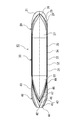
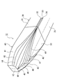
- FIG. 1 is a side view of a hull showing an example of a configuration in which an outer plate surface of a steel ship or a light alloy ship according to an embodiment of the present invention is formed by an assembly of strip-like plate members.
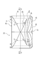
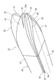
- FIG. 2 is a bottom view of the hull of FIG. 3 is a front view of the hull showing the configuration of the bow side of the hull of FIG. 4 is a partial perspective view showing the configuration of the bow side of the hull of FIG.
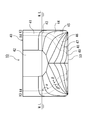
- FIG. 5 is a rear view of the hull showing the configuration of the stern side of the hull of FIG. 6 is a partial perspective view showing the configuration of the stern side of the hull of FIG.
- the ship to which the present invention is applied is a steel ship or a light alloy ship equipped with a propulsion device, and preferably the planned voyage speed is 0.1 to 0.5 in terms of fluid number.
- passenger ships such as tourist ships, ferry terminals, tankers, liquefied gas ships, chemical ships, bulk carriers, ore carriers, car carriers, container ships, cargo ships such as self-defense ships, and patrols It covers ships, special ships such as fireboats and oceanographic survey ships, and excludes planing boats and wooden ships with simple shapes.
- the fluid number is, for example, about 0.15 for a relatively low-speed tanker ship and about 0.26 to 0.28 for a relatively high-speed container ship.
- the effect of the present invention can be greatly obtained for general merchant ships that are required to be operated efficiently at a speed mainly designed for the open ocean.
- the Froude number is often set to 0.13 to 0.30, and the effect is expected especially for those ships.
- complicated curved surfaces are frequently used in the bow and stern parts excluding the parallel part, and many effects of reducing the complicated bending work of the present invention are expected. Therefore, the present invention is particularly effective for a ship having a relatively low fluid number of 0.13 to 0.30 because of the increase in resistance and the construction cost.
- the outer plate occupying 90% or more and 100% or less of the outer plate surface area of the main hull is formed by two-dimensional bending. It is formed by a belt-like plate member that has only one or both of possible surfaces and a plane and extends in the longitudinal direction of the hull.
- most of the outer plate surface has only one or both of a plane and a plane that can be formed by two-dimensional bending, and the strip-shaped plate members 21 to 26, 31 to 35 extending in the longitudinal direction of the hull. It is formed of 41 to 50 aggregates.
- These belt-like plate members 21 to 26, 31 to 35, and 41 to 50 are flat surfaces or surfaces that can be formed by roller bending, and can be produced without the need for a three-dimensional bending iron work or pressing work. It is.
- the area of the outer plate surface does not include energy-saving addenda such as fins and ducts, rudder, stan tube, and biaxial ship strut. If the ratio of the belt-like plate members 21 to 26, 31 to 35, 41 to 50 is less than 90% of the outer surface area of the hull, the surface that requires the third bending remains, and the iron work and press work The reduction effect is small, the influence of performance deterioration is large, and the merit of this configuration is reduced.
- the belt-like plate members 21 to 26, 31 to 35, and 41 to 50 that have only one or both of the surfaces that can be formed by two-dimensional bending process occupy most of the outer plate surface.
- no special technique or machine tool is required.
- the production of the outer plate block for building the ship block is only a process of cutting the flat plate and bending it two-dimensionally, so there is no need for a skilled engineer or special equipment.
- the outer plate block (ship part) can be manufactured anywhere with a roller.
- process management at the shipyard becomes easy, and the lead time, which is the period from the start to the end of the work, can be expected to be reduced, so that a low-cost construction cost can be realized and an inexpensive ship can be provided.
- the lower outer plate has many cubic curved surfaces, so L.
- the outer plate occupying 90% or more and 100% or less of the lower outer plate surface is preferably constituted by an aggregate of band-shaped plate members 22 to 27, 31 to 35, and 41 to 50.
- the outer plate portion which is relatively bent in a conventional ship, is formed by the belt-like plate members 22 to 27, 31 to 35, and 41 to 50, so that the effect of reducing the number of processing steps is increased.
- the ratio of the strip-shaped plate member is the full-length draft line W. L. If it is less than 90% of the surface area of the lower outer plate, the surface that requires the third bending remains, the effect of reducing the iron work and press work is small, the effect of performance deterioration is large, and the merit of this configuration Decrease.
- the adjacent band-shaped plate members 22 to 27 are preferably 80% or more and 100% or less of the adjacent bonding portions (knuckles). If the angle (knuckle angle) 43 to 50 in the cross section of the hull ( ⁇ shown in FIGS. 3 and 5) is greater than 90 degrees and less than 270 degrees, the angle when straddling the joint becomes smaller and resistance increases. Can be suppressed. If the knuckle angle is 90 degrees or less or 270 degrees or more, the angle at which the flow is refracted at the joint (knuckle portion) becomes steep, and the suppression of the increase in resistance becomes insufficient.
- the knuckle angle is desirably in the range of 130 degrees to 230 degrees.
- the knuckle angle is 170 degrees or more and 190 degrees or less, the number of divisions of the strip-shaped plate member increases, the number of processes increases, and the merit decreases.
- the full-length waterline W. at least one of the bow and stern (both in this embodiment) is selected.
- L. Preferably 80% or more and 100% or less of the adjacent joints (knuckles) of the lower belt-like plate members 22 to 27 and 43 to 50 are directly or other than the bilge parts 32 to 35 of the hull central part 30. It connects and comprises via a junction part.
- the joining portions of the belt-like plate members 22 to 27 and 43 to 50 can be converged on the bilge portions 32 to 35, and the angle when the streamlines straddle the joining portions can be reduced.
- An increase in resistance can be suppressed, and deterioration of propulsion performance can be avoided as much as possible.
- the outer plate surface can be easily approximated by an aggregate of strip-like plate members while preventing the performance from deteriorating. .
- the axis of bending of the surface that can be formed by two-dimensional bending of the belt-like plate members 21 to 27 and 41 to 50 is in the cross section of the hull and is in parallel.
- the dotted lines indicating the axes are formed so as to be parallel in the same belt-like plate members 21 to 27 and 41 to 50, the original complex shape is not obtained.
- the work of replacing the hull shape constituted by a curved surface with an assembly of strip-like plate members 21 to 27 and 41 to 50 is further simplified.
- the cross sections perpendicular to the longitudinal direction of the hulls of the strip-like plate members 21 to 27 and 41 to 50 are parallel to each other in the hull longitudinal direction. That is, when viewed from the front of the hull, the inclination ⁇ of the cross section of each of the belt-like plate members 21 to 27 and 41 to 50 is constant.
- the outer plate that occupies 50% or more and 100% or less of the outer plate surface of the hull between the position of the bow end and the position behind the bow vertical line by a distance 0.1 times the length between the vertical lines. Is preferably formed by the belt-like plate members 22 to 27 as shown in FIGS. 3 and 4, for example.
- the ratio of the strip-shaped plate member is less than 50% of the outer plate surface area of the bow side portion, the surface that requires the third bending remains, and the reduction effect of the iron work and press work is small, and the performance deteriorates. The impact is increased and the benefits of this configuration are reduced.
- the bow flare portion is formed by the strip-shaped plate member 21 on the bow side, and the lower side from the knuckle line is formed by the strip-shaped plate member 22 on the bow side.
- the bow valve has a bow-like plate member 23 on the upper surface, a belt-like member 22a branched from the bow-like plate member 22 on the bow side, and belt-like plate members 24, 25 on the bow side, and a lower surface on the bow-side plate.
- the member 26 is formed.
- the bottom surface is formed by the belt-like plate member 27 on the bow side. A portion near the front end of the strip-shaped plate member 27 on the bow side is bent upward.
- the bow valve it is possible to easily provide the bow valve by adding the belt-like plate member 23 at the bow portion.
- the belt-like plate member 23 does not extend to the bilge part, the joint (knuckle) lines with the adjacent belt-like plate members 22 and 24 are gathered together, or the joint lines are gathered.
- a curved plate member formed by three-dimensional bending is provided in the portion to be processed. Thereby, a bow valve shape can be formed easily and the effect of a bow valve can be acquired.
- the bow-side belt-like plate members 24 and 25 that form the side surfaces and the bow-side belt-like plate member 26 that forms the lower surface are parallel to the belt-like plate members 32, 33, and 34 that form the bilge portion of the hull parallel portion 30, respectively. Connecting. Further, the bow-side strip member 27 that forms the bottom surface is connected to the parallel strip member 35 that forms the bottom surface of the hull parallel portion 30. Thereby, the junction part (knuckle) of the strip
- the number of strip-like plate members 21 to 27 on the bow side is 13 on both sides in the ship 10 of this embodiment, but is preferably 9 or more and 17 or less. If the number is less than 9, the shape is simplified and the performance of the ship may be lowered. If the number is 17 or more, the number of joints increases, and the number of building steps increases.
- the bow side often has a bow valve or the like that requires a particularly complicated bending process in a conventional ship, and the outer plate portion of the bow portion is formed by the belt-like plate members 21 to 27.
- the effect of reducing the processing man-hour is remarkably increased.
- the hull parallel portion 30 having the same cross section is formed by the belt-like plate members 31 to 35 having only a plane surface, and the cross section shape of the bilge portion is a polygonal shape.
- a vertical hull side surface is formed by a parallel strip-shaped plate member 31, and a ship bottom is formed by a parallel strip-shaped plate member 35.
- a bilge portion between the parallel strip-shaped plate member 31 and the parallel strip-shaped plate member 35 is formed by three parallel strip-shaped plate members 32, 33 and 34. That is, the semicircular portion is formed by the belt-like plate members 32, 33, and 34 in parallel portions of three planes.
- the strip-like plate members 32, 33, and 34 of the three parallel portions have the same dimensions, so that it is easy to cut and cut the plate.
- the number of the strip-like plate members 31 to 35 in the parallel portion is 9 on both sides in the ship 10 of this embodiment, but is preferably 7 or more and 13 or less. If the number is less than 7, the shape is simplified and the performance of the ship may be deteriorated. If the number is 13 or more, the number of joints increases and the number of building man-hours increases.
- the bilge portion having a cross-sectional shape in the prior art has an arc shape, and a portion that needs to be bent can be formed by a flat assembly, so that it can be produced only by cutting and welding plate members.
- the upper part has many relatively simple shapes.
- L. The outer plate that occupies 50% or more and 100% or less of the outer plate surface of the hull between the position of the stern end and the position forward of a distance of 0.1 times the length between the vertical line from the bow perpendicular. Is preferably formed of band-shaped plate members, for example, as shown in FIGS. 5 and 6, formed of band-shaped plate members 41 to 50 on the stern side.
- the proportion of the strip-shaped plate member is less than 50% of the outer plate surface area of the stern side portion, the surface that requires the third bending remains, and the reduction effect of the iron work and press work is small, and the performance deteriorates. The impact is increased and the benefits of this configuration are reduced.
- the stern side surface is formed by the stern side strip member 41, and the transom having a large planar shape at the stern end is formed by the stern side strip member 42.
- the upper ship bottom side is formed by the stern side strip members 43, 44, 45, the lower ship bottom side is formed by the stern side strip members 46, 47, 48, 49, and the bottom of the stern is formed. It is formed by the side belt-like plate member 50.
- the flat stern plate member 41 on the stern side forming this side surface is connected to the stern plate member 42 on the stern side forming the transom. Further, the stern-side strip members 43, 44, and 45 that form the upper ship bottom side portion are also connected to the stern-side strip member 42 that forms the transom. On the other hand, the stern-side plate members 46, 47, 48, and 49 that form the bottom side of the bottom side of the stern are formed by connecting the port side member and the starboard side member to each other to form the stern end. A stun tube (not shown) into which the propeller shaft is inserted is provided at the stern end.
- strip-shaped plate members 46, 47, 48 are provided.
- the strip-shaped plate members 46, 47, 48 are provided up to the parallel portion 30 in the configuration of FIGS. Although it is extended, it may be gathered into a point at an appropriate position in front of it (stern side), and the strip plate member may be closed. Further, a curved plate member formed by three-dimensional bending may be provided at a portion where the lines of the joint portions of the belt-like plate member are aggregated. Thereby, it is possible to reflect the feature of the shape formed by the three-dimensional bending in the original hull shape with respect to the flow of water to the propulsion device also in the hull shape of the ship 10.
- the stern side strip plate member 41 forming the stern side surface forms the side surface of the hull parallel portion 30.
- the stern-side strip members 43 and 44 connected to the member 31 and forming the upper bottom side portion, and the stern side strip member 49 forming the lower bottom side portion are the bilge portion of the hull parallel portion 30. It connects to the strip
- the stern-side strip member 50 that forms the bottom surface is connected to the parallel strip member 35 that forms the bottom surface of the hull parallel portion 30.
- the stern side band plate member 45 forming the upper bottom side part and the stern side band member 46, 47, 48 forming the lower bottom side part are the stern side band member 44 and the stern side. It becomes thin and becomes one point as it goes to the bow side between the belt-like plate members 49 on the side.
- the joining portions (knuckles) of the belt-like plate members 42 to 49 are converged to the bilge portions 32, 33, and 34, and the angle when the streamlines straddle the joining portions is configured to be small.
- the number of the strip-like plate members 41 to 50 on the stern side is 17 on both sides in the ship 10 of this embodiment, but is preferably 13 or more and 21 or less. If the number is less than 13, the shape is simplified and the performance of the ship may be lowered. If the number is 21 or more, the number of joints increases and the number of building man-hours increases.
- the stern side has a complicated stern shape that requires bending after the bow portion in the conventional ship, and the outer plate portion of the stern portion is often used as a belt-like plate member 41 to 50 on the stern side. Therefore, the effect of reducing the processing man-hour is remarkably increased.
- the outer plate surface can be easily formed on the outer plate surface while suppressing the deterioration of the performance of the ship having the excellent performance of the conventional ship having a curved surface of three-dimensional bending. It can be approximated by an assembly of members 21 to 27, 31 to 35, and 41 to 50.
Landscapes
- Ocean & Marine Engineering (AREA)
- Chemical & Material Sciences (AREA)
- Engineering & Computer Science (AREA)
- Combustion & Propulsion (AREA)
- Mechanical Engineering (AREA)
- Fluid Mechanics (AREA)
- Physics & Mathematics (AREA)
- Metal Rolling (AREA)
- Bending Of Plates, Rods, And Pipes (AREA)
- Shaping Metal By Deep-Drawing, Or The Like (AREA)
- Other Liquid Machine Or Engine Such As Wave Power Use (AREA)
- Pressure Welding/Diffusion-Bonding (AREA)
- Electroplating Methods And Accessories (AREA)
Abstract
Description
20 船首側部分
21~27 船首側の帯状板部材
30 船体平行部
31~35 平行部の帯状板部材
40 船尾側部分
41~50 船尾側の帯状板部材
Claims (10)
- 推進装置を装備する鋼船又は軽合金船において、主船体の外板表面積の90%以上でかつ100%以下を占める外板を、2次元曲げ加工で形成可能な面と平面のいずれかの面又は両方の面しか持たず、かつ、船体長手方向に延びる帯状板部材で形成することを特徴とする鋼船又は軽合金船。
- 満載喫水線より下の外板表面の90%以上でかつ100%以下を占める外板を、前記帯状板部材で形成したことを特徴とする請求項1に記載の鋼船又は軽合金船。
- 少なくとも船首又は船尾の一方における満載喫水線下の前記帯状板部材の隣接する相互間の接合部において、隣接する前記帯状板部材が船体横断面内でなす角度を90度より大きく270度未満としたことを特徴とする請求項1又は2に記載の鋼船又は軽合金船。
- 少なくとも船首又は船尾の一方における満載喫水線下の前記帯状板部材の隣接する相互間の接合部を船体中央部のビルジ部に直接又はほかの接合部を介して接続して構成したことを特徴とする請求項1~3のいずれか1項に記載の鋼船又は軽合金船。
- 満載喫水線より下で、かつ、船首端の位置と船首垂線から垂線間長の0.1倍の距離後方の位置との間において、船体の外板表面の50%以上でかつ100%以下を占める外板を、前記帯状板部材で形成したことを特徴とする請求項1~4のいずれか1項に記載の鋼船又は軽合金船。
- 船首バルブの部分に関して、船首部の帯状板部材を追加すると共に、該追加した帯状板部材が前記ビルジ部まで延びていかないように、該追加した帯状板部材と隣接する帯状板部材との間の接合部を点に集約するか、若しくは、該追加した帯状板部材と隣接する帯状板部材との間の接合部が集約する部分に3次元曲げで形成される曲面状の板部材を設けたことを特徴とする請求項1~5のいずれか1項に記載の鋼船又は軽合金船。
- 満載喫水線より下で、かつ、船尾端の位置と船尾垂線から垂線間長の0.1倍の距離前方の位置との間において、船体の外板表面の50%以上でかつ100%以下を占める外板を、前記帯状板部材で形成したことを特徴とする請求項1~6のいずれか1項に記載の鋼船又は軽合金船。
- 船尾のスタンチューブ周りに関して、船尾のスタンチューブ周りの形状を作るための帯状板部材を、平行部まで延ばすか、もしくは、前記平行部より船尾側の部位で、点に集約して、当該帯状板部材を閉じるか、若しくは、当該帯状板部材の接合部が集約する部分に3次元曲げで形成される曲面状の板部材を設けたことを特徴とする請求項1~7のいずれか1項に記載の鋼船又は軽合金船。
- 船体平行部を平面の面しか持たない前記帯状板部材で形成し、ビルジ部分の横断面形状を多角形形状としたことを特徴とする請求項1~8のいずれか1項に記載の鋼船又は軽合金船。
- 船体を正面線図で見て、それぞれの前記帯状板部材の船体長手方向に垂直な断面が船体前後方向にわたって、その帯状板部材で平行になることを特徴とする請求項1~9のいずれか1項に記載の鋼船又は軽合金船。
Priority Applications (3)
| Application Number | Priority Date | Filing Date | Title |
|---|---|---|---|
| PH1/2014/501070A PH12014501070A1 (en) | 2011-12-22 | 2012-12-14 | Steel ship or light alloy ship |
| KR1020147012945A KR101645215B1 (ko) | 2011-12-22 | 2012-12-14 | 강선 또는 경합금선 |
| CN201280063333.8A CN103998332B (zh) | 2011-12-22 | 2012-12-14 | 钢船或者轻合金船 |
Applications Claiming Priority (2)
| Application Number | Priority Date | Filing Date | Title |
|---|---|---|---|
| JP2011-281846 | 2011-12-22 | ||
| JP2011281846A JP5778572B2 (ja) | 2011-12-22 | 2011-12-22 | 鋼船又は軽合金船 |
Publications (1)
| Publication Number | Publication Date |
|---|---|
| WO2013094534A1 true WO2013094534A1 (ja) | 2013-06-27 |
Family
ID=48668425
Family Applications (1)
| Application Number | Title | Priority Date | Filing Date |
|---|---|---|---|
| PCT/JP2012/082511 Ceased WO2013094534A1 (ja) | 2011-12-22 | 2012-12-14 | 鋼船又は軽合金船 |
Country Status (5)
| Country | Link |
|---|---|
| JP (1) | JP5778572B2 (ja) |
| KR (1) | KR101645215B1 (ja) |
| CN (1) | CN103998332B (ja) |
| PH (1) | PH12014501070A1 (ja) |
| WO (1) | WO2013094534A1 (ja) |
Cited By (1)
| Publication number | Priority date | Publication date | Assignee | Title |
|---|---|---|---|---|
| WO2017167602A1 (en) * | 2016-03-29 | 2017-10-05 | Hermitage Family Office Sarl | Yacht |
Families Citing this family (7)
| Publication number | Priority date | Publication date | Assignee | Title |
|---|---|---|---|---|
| JP2017036014A (ja) * | 2015-08-12 | 2017-02-16 | 三井造船株式会社 | 洋上浮体構造物 |
| JP2018131173A (ja) * | 2017-02-17 | 2018-08-23 | 株式会社三井E&Sホールディングス | 船体構造 |
| JP2019001321A (ja) * | 2017-06-15 | 2019-01-10 | 三井E&S造船株式会社 | 洋上浮体構造物 |
| CN107585257B (zh) * | 2017-08-23 | 2023-12-05 | 杭州现代船舶设计研究有限公司 | 一种千吨级散货船船型 |
| JP7227728B2 (ja) * | 2018-10-10 | 2023-02-22 | 三菱造船株式会社 | 既存船舶の利用方法 |
| KR102818633B1 (ko) * | 2022-07-07 | 2025-06-11 | 에이치디한국조선해양 주식회사 | 선박 |
| CN115556881B (zh) * | 2022-10-09 | 2024-12-03 | 中国船舶集团有限公司第七○八研究所 | 一种舭部凸起的破冰船型 |
Citations (3)
| Publication number | Priority date | Publication date | Assignee | Title |
|---|---|---|---|---|
| DE1269911B (de) * | 1965-07-13 | 1968-06-06 | Blohm Voss Ag | Schiffsform fuer schnellfahrende Frachtschiffe |
| US4489976A (en) * | 1982-12-09 | 1984-12-25 | Flaherty B Michael | Vehicle body |
| WO1994006675A1 (fr) * | 1992-09-16 | 1994-03-31 | Etinter | Procede de fabrication d'une coque de bateau et coque de bateau ainsi obtenue |
Family Cites Families (8)
| Publication number | Priority date | Publication date | Assignee | Title |
|---|---|---|---|---|
| FR667717A (fr) * | 1928-04-23 | 1929-10-21 | Perfectionnements à la fabrication des coques de navires | |
| CH483336A (de) * | 1966-11-15 | 1969-12-31 | Inst Schiffbau | Schiffskörper für Verdrängungsschiffe |
| US4550673A (en) * | 1983-06-02 | 1985-11-05 | Sigurdur Ingvason | Hull construction for seagoing vessels |
| US5279249A (en) * | 1991-12-27 | 1994-01-18 | Outboard Marine Corporation | Boat construction |
| JPH08239082A (ja) * | 1995-03-06 | 1996-09-17 | Ishikawajima Harima Heavy Ind Co Ltd | 船首バルブ付き船舶 |
| US6287717B1 (en) * | 1998-11-13 | 2001-09-11 | Gore Enterprise Holdings, Inc. | Fuel cell membrane electrode assemblies with improved power outputs |
| JP4421495B2 (ja) * | 2005-03-04 | 2010-02-24 | 三井造船株式会社 | 高速双胴船 |
| CN200942862Y (zh) * | 2006-08-23 | 2007-09-05 | 国营武昌造船厂 | 一种大型客滚船船型 |
-
2011
- 2011-12-22 JP JP2011281846A patent/JP5778572B2/ja not_active Expired - Fee Related
-
2012
- 2012-12-14 WO PCT/JP2012/082511 patent/WO2013094534A1/ja not_active Ceased
- 2012-12-14 CN CN201280063333.8A patent/CN103998332B/zh not_active Expired - Fee Related
- 2012-12-14 KR KR1020147012945A patent/KR101645215B1/ko not_active Expired - Fee Related
- 2012-12-14 PH PH1/2014/501070A patent/PH12014501070A1/en unknown
Patent Citations (3)
| Publication number | Priority date | Publication date | Assignee | Title |
|---|---|---|---|---|
| DE1269911B (de) * | 1965-07-13 | 1968-06-06 | Blohm Voss Ag | Schiffsform fuer schnellfahrende Frachtschiffe |
| US4489976A (en) * | 1982-12-09 | 1984-12-25 | Flaherty B Michael | Vehicle body |
| WO1994006675A1 (fr) * | 1992-09-16 | 1994-03-31 | Etinter | Procede de fabrication d'une coque de bateau et coque de bateau ainsi obtenue |
Cited By (2)
| Publication number | Priority date | Publication date | Assignee | Title |
|---|---|---|---|---|
| WO2017167602A1 (en) * | 2016-03-29 | 2017-10-05 | Hermitage Family Office Sarl | Yacht |
| NL2016506B1 (en) * | 2016-03-29 | 2017-10-06 | Hermitage Family Office Sarl | Yacht. |
Also Published As
| Publication number | Publication date |
|---|---|
| CN103998332A (zh) | 2014-08-20 |
| KR20140084186A (ko) | 2014-07-04 |
| JP5778572B2 (ja) | 2015-09-16 |
| KR101645215B1 (ko) | 2016-08-03 |
| PH12014501070A1 (en) | 2014-06-30 |
| CN103998332B (zh) | 2017-03-29 |
| JP2013129389A (ja) | 2013-07-04 |
Similar Documents
| Publication | Publication Date | Title |
|---|---|---|
| JP5778572B2 (ja) | 鋼船又は軽合金船 | |
| Molland et al. | Reducing ship emissions: a review of potential practical improvements in the propulsive efficiency of future ships | |
| Savitsky | Planing craft | |
| US10988210B2 (en) | Hybrid chine boat hull and methods of manufacture and use | |
| EP3305651A1 (en) | Articulated tug barge hull | |
| US20210316817A1 (en) | Hybrid chine boat hull and methods of manufacture and use | |
| Sanders et al. | Aluminum applications in marine transportation | |
| JP2005537175A (ja) | 喫水線よりも下に位置するフォイルを備えた船舶 | |
| RU2527244C1 (ru) | Кормовая оконечность двухвального судна | |
| JP2010047248A (ja) | 船尾波干渉フィン | |
| US12179883B2 (en) | Hybrid chine boat hull and methods of manufacture and use | |
| CN202847963U (zh) | 敞开式前甲板类登陆艇 | |
| CN104220327A (zh) | 海洋船体和海洋船舶 | |
| JP5969170B2 (ja) | 船舶 | |
| CA2964797C (en) | Minimum wave bow | |
| JP5264093B2 (ja) | 船舶用舵、船舶用舵のラダーホーン及び船舶 | |
| JP5819764B2 (ja) | 船舶及びその船舶の設計方法 | |
| JP2023514098A (ja) | 操向装置及びそれを備える船舶 | |
| JP4216858B2 (ja) | 船舶 | |
| JPH06344973A (ja) | 船尾構造 | |
| JP4712673B2 (ja) | 船舶及びその船首構造 | |
| KR102376325B1 (ko) | 선박 | |
| JPH0911972A (ja) | 船舶推力増加方法及びこれに用いる装置 | |
| JP2019156309A (ja) | 船尾フィン及び船舶 | |
| TWI772675B (zh) | 特別是用於貨櫃船、散裝貨船或油輪之船體 |
Legal Events
| Date | Code | Title | Description |
|---|---|---|---|
| 121 | Ep: the epo has been informed by wipo that ep was designated in this application |
Ref document number: 12858819 Country of ref document: EP Kind code of ref document: A1 |
|
| WWE | Wipo information: entry into national phase |
Ref document number: 12014501070 Country of ref document: PH |
|
| ENP | Entry into the national phase |
Ref document number: 20147012945 Country of ref document: KR Kind code of ref document: A |
|
| NENP | Non-entry into the national phase |
Ref country code: DE |
|
| 122 | Ep: pct application non-entry in european phase |
Ref document number: 12858819 Country of ref document: EP Kind code of ref document: A1 |