WO2013084919A1 - 照明装置 - Google Patents
照明装置 Download PDFInfo
- Publication number
- WO2013084919A1 WO2013084919A1 PCT/JP2012/081468 JP2012081468W WO2013084919A1 WO 2013084919 A1 WO2013084919 A1 WO 2013084919A1 JP 2012081468 W JP2012081468 W JP 2012081468W WO 2013084919 A1 WO2013084919 A1 WO 2013084919A1
- Authority
- WO
- WIPO (PCT)
- Prior art keywords
- light
- light source
- light emitting
- emitting element
- terminal
- Prior art date
- Legal status (The legal status is an assumption and is not a legal conclusion. Google has not performed a legal analysis and makes no representation as to the accuracy of the status listed.)
- Ceased
Links
Images



Classifications
-
- F—MECHANICAL ENGINEERING; LIGHTING; HEATING; WEAPONS; BLASTING
- F21—LIGHTING
- F21V—FUNCTIONAL FEATURES OR DETAILS OF LIGHTING DEVICES OR SYSTEMS THEREOF; STRUCTURAL COMBINATIONS OF LIGHTING DEVICES WITH OTHER ARTICLES, NOT OTHERWISE PROVIDED FOR
- F21V5/00—Refractors for light sources
- F21V5/008—Combination of two or more successive refractors along an optical axis
-
- F—MECHANICAL ENGINEERING; LIGHTING; HEATING; WEAPONS; BLASTING
- F21—LIGHTING
- F21V—FUNCTIONAL FEATURES OR DETAILS OF LIGHTING DEVICES OR SYSTEMS THEREOF; STRUCTURAL COMBINATIONS OF LIGHTING DEVICES WITH OTHER ARTICLES, NOT OTHERWISE PROVIDED FOR
- F21V14/00—Controlling the distribution of the light emitted by adjustment of elements
- F21V14/06—Controlling the distribution of the light emitted by adjustment of elements by movement of refractors
-
- F—MECHANICAL ENGINEERING; LIGHTING; HEATING; WEAPONS; BLASTING
- F21—LIGHTING
- F21V—FUNCTIONAL FEATURES OR DETAILS OF LIGHTING DEVICES OR SYSTEMS THEREOF; STRUCTURAL COMBINATIONS OF LIGHTING DEVICES WITH OTHER ARTICLES, NOT OTHERWISE PROVIDED FOR
- F21V5/00—Refractors for light sources
- F21V5/04—Refractors for light sources of lens shape
-
- F—MECHANICAL ENGINEERING; LIGHTING; HEATING; WEAPONS; BLASTING
- F21—LIGHTING
- F21V—FUNCTIONAL FEATURES OR DETAILS OF LIGHTING DEVICES OR SYSTEMS THEREOF; STRUCTURAL COMBINATIONS OF LIGHTING DEVICES WITH OTHER ARTICLES, NOT OTHERWISE PROVIDED FOR
- F21V23/00—Arrangement of electric circuit elements in or on lighting devices
- F21V23/04—Arrangement of electric circuit elements in or on lighting devices the elements being switches
-
- F—MECHANICAL ENGINEERING; LIGHTING; HEATING; WEAPONS; BLASTING
- F21—LIGHTING
- F21Y—INDEXING SCHEME ASSOCIATED WITH SUBCLASSES F21K, F21L, F21S and F21V, RELATING TO THE FORM OR THE KIND OF THE LIGHT SOURCES OR OF THE COLOUR OF THE LIGHT EMITTED
- F21Y2105/00—Planar light sources
- F21Y2105/10—Planar light sources comprising a two-dimensional [2D] array of point-like light-generating elements
- F21Y2105/14—Planar light sources comprising a two-dimensional [2D] array of point-like light-generating elements characterised by the overall shape of the two-dimensional [2D] array
- F21Y2105/16—Planar light sources comprising a two-dimensional [2D] array of point-like light-generating elements characterised by the overall shape of the two-dimensional [2D] array square or rectangular, e.g. for light panels
-
- F—MECHANICAL ENGINEERING; LIGHTING; HEATING; WEAPONS; BLASTING
- F21—LIGHTING
- F21Y—INDEXING SCHEME ASSOCIATED WITH SUBCLASSES F21K, F21L, F21S and F21V, RELATING TO THE FORM OR THE KIND OF THE LIGHT SOURCES OR OF THE COLOUR OF THE LIGHT EMITTED
- F21Y2105/00—Planar light sources
- F21Y2105/10—Planar light sources comprising a two-dimensional [2D] array of point-like light-generating elements
- F21Y2105/14—Planar light sources comprising a two-dimensional [2D] array of point-like light-generating elements characterised by the overall shape of the two-dimensional [2D] array
- F21Y2105/18—Planar light sources comprising a two-dimensional [2D] array of point-like light-generating elements characterised by the overall shape of the two-dimensional [2D] array annular; polygonal other than square or rectangular, e.g. for spotlights or for generating an axially symmetrical light beam
-
- F—MECHANICAL ENGINEERING; LIGHTING; HEATING; WEAPONS; BLASTING
- F21—LIGHTING
- F21Y—INDEXING SCHEME ASSOCIATED WITH SUBCLASSES F21K, F21L, F21S and F21V, RELATING TO THE FORM OR THE KIND OF THE LIGHT SOURCES OR OF THE COLOUR OF THE LIGHT EMITTED
- F21Y2113/00—Combination of light sources
- F21Y2113/10—Combination of light sources of different colours
- F21Y2113/13—Combination of light sources of different colours comprising an assembly of point-like light sources
-
- F—MECHANICAL ENGINEERING; LIGHTING; HEATING; WEAPONS; BLASTING
- F21—LIGHTING
- F21Y—INDEXING SCHEME ASSOCIATED WITH SUBCLASSES F21K, F21L, F21S and F21V, RELATING TO THE FORM OR THE KIND OF THE LIGHT SOURCES OR OF THE COLOUR OF THE LIGHT EMITTED
- F21Y2113/00—Combination of light sources
- F21Y2113/30—Combination of light sources of visible and non-visible spectrum
-
- F—MECHANICAL ENGINEERING; LIGHTING; HEATING; WEAPONS; BLASTING
- F21—LIGHTING
- F21Y—INDEXING SCHEME ASSOCIATED WITH SUBCLASSES F21K, F21L, F21S and F21V, RELATING TO THE FORM OR THE KIND OF THE LIGHT SOURCES OR OF THE COLOUR OF THE LIGHT EMITTED
- F21Y2115/00—Light-generating elements of semiconductor light sources
- F21Y2115/10—Light-emitting diodes [LED]
Definitions
- the present invention relates to a lighting device.
- This application claims priority based on Japanese Patent Application No. 2011-266803 filed on Dec. 6, 2011, the contents of which are incorporated herein by reference.
- An illumination device using a light emitting diode is known (for example, see Patent Document 1). Since an illumination device using LEDs can be thinned, it can be used for various purposes as compared with a conventional illumination device.
- An object of an aspect of the present invention is to provide an illuminating device capable of irradiating light that matches a user's sense.
- a light source unit having a first light source that emits visible light and a second light source that emits infrared light, a first mode in which both the visible light and the infrared light are irradiated, and
- an illumination device including a control unit that controls the light source unit according to a mode selected from the second mode in which only the visible light is irradiated.
- an illuminating device capable of irradiating light that matches a user's sense.
- FIG. 3 is a diagram showing a configuration along a cross section A1-A2-A3-A4 in FIG. 2; It is a disassembled perspective view which shows the other structure of the illuminating device which concerns on this embodiment. It is a perspective view which shows the other structure of the illuminating device which concerns on this embodiment.
- FIG. 1 is a perspective view showing the configuration of the illumination device according to the present embodiment.
- the lighting device LGT includes a light source unit 100, an adjustment unit 200, and a control unit CONT.
- the light source unit 100, the adjustment unit 200, and the control unit CONT are integrally provided by a case 300 or the like.
- An arrow D indicates the traveling direction of the illumination light.
- the illuminating device LGT is attached to, for example, a ceiling part of a room such as a house, and irradiates illuminated light such as walls, floors, and indoor spaces.
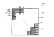
- FIG. 2 is a plan view showing the configuration of the light source unit 100.
- the light source unit 100 includes a substrate 10 and a display element 20.
- the light source unit 100 has a configuration in which a plurality of display elements 20 are mounted on the mounting surface 10a of the substrate 10 in a matrix, for example.
- the display element 20 is provided, for example, in a state where it is spread on the substrate 10 without a gap.
- the substrate 10 is provided with a wiring (not shown), a driver (not shown) for driving the display element 20, and the like.
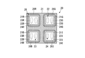
- FIG. 3 is a plan view showing the configuration of the package unit 21.
- the display element 20 includes a package part 21, a light emitting part 22, and a solder part 23.
- the light emitting unit 22 is mounted on the package unit 21 via a solder unit 23 by a so-called flip chip type mounting method.
- the package portion 21 is provided with four accommodating portions 21R, 21G, 21B, and 21I.
- the four accommodating portions 21R, 21G, 21B, and 21I are arranged in a matrix of 2 rows ⁇ 2 columns.
- the package unit 21 has a receiving unit side terminal unit 24.
- the accommodating portion side terminal portion 24 has four terminals 24R, 24G, 24B, and 24I.
- the terminal 24R is provided at the bottom of the red light emitting element 22R.
- the terminal 24G is provided at the bottom of the green light emitting element 22G.
- the terminal 24B is provided at the bottom of the blue light emitting element 22B.
- the terminal 24I is provided at the bottom of the infrared light emitting element 22I.
- the light emitting unit 22 includes four light emitting elements, a red light emitting element 22R, a green light emitting element 22G, a blue light emitting element 22B, and an infrared light emitting element 22I.
- the red light emitting element 22R is accommodated in a substantially central position in the plan view of the accommodating portion 21R.
- the green light emitting element 22G is accommodated in a substantially central position in the plan view of the accommodating portion 21G.
- the blue light emitting element 22B is accommodated in a substantially central position in the plan view of the accommodating portion 21B.
- the infrared light emitting element 22I is accommodated at a substantially central position in the plan view of the accommodating portion 21I.
- a light emitting diode (LED) chip or the like is used as each of the light emitting elements 22R, 22G, 22B, and 22I.
- FIG. 4 is a diagram showing a configuration along the section A1-A2-A3-A4 in FIG. As shown in FIG. 4, the light emitting part 22 has an element side terminal part 25.
- the element side terminal portion 25 has terminals 25R, 25G, 25B, and 25I.
- the terminal 25R is formed at the bottom of the accommodating portion 21R.
- the terminal 25R is disposed to face the terminal 24R in a state where the red light emitting element 22R is accommodated in the accommodating portion 21R.
- the terminal 25R is connected to the terminal 24R via the solder 23R.
- the terminal 25R exchanges electrical signals between the red light emitting element 22R and the terminal 24R.
- the terminal 25G is formed at the bottom of the accommodating portion 21G.
- the terminal 25G is disposed to face the terminal 24G in a state where the green light emitting element 22G is accommodated in the accommodating portion 21G.
- the terminal 25G is connected to the terminal 24G via the solder 23G.
- the terminal 25G exchanges electrical signals between the green light emitting element 22G and the terminal 24G.
- the terminal 25B is formed at the bottom of the accommodating portion 21B.
- the terminal 25B is disposed to face the terminal 24B in a state where the blue light emitting element 22B is accommodated in the accommodating portion 21B.
- the terminal 25B is connected to the terminal 24B via the solder 23B.
- the terminal 25B exchanges electrical signals between the blue light emitting element 22B and the terminal 24B.
- the terminal 25I is formed at the bottom of the accommodating portion 21I.
- the terminal 25I is disposed to face the terminal 24I in a state where the infrared light emitting element 22I is housed in the housing portion 21I.
- the terminal 25I is connected to the terminal 24I via the solder 23I.
- the terminal 25I exchanges electrical signals between the infrared light emitting element 22I and the terminal 24I.
- the package part 21 has a sealing part 26.
- the sealing portion 26 includes sealing members 26R, 26G, 26B, and 26I.
- the sealing member 26R seals the accommodating portion 21R.
- the sealing member 26G seals the accommodating portion 21G.
- the sealing member 26B seals the accommodating portion 21B.
- the sealing member 26I seals the accommodating portion 21I.
- the sealing members 26R, 26G, 26B, and 26I are formed with lens portions 27R, 27G, 27B, and 27I that collect the light from the light emitting portion 22, respectively.
- the control unit CONT controls the light source unit 100 so that the irradiated unit is irradiated with light including at least visible light (red light, green light, and blue light) when the light source unit 100 is turned on. Specifically, the light source unit 100 is switched between a first mode in which both visible light and infrared light are irradiated and a second mode in which only visible light is irradiated.
- the adjustment unit 200 adjusts the irradiation range of the light irradiated to the irradiated portion.
- the adjustment unit 200 includes a fly-eye lens (light adjustment layer) 40 in which a plurality of lens elements 41 that divide and emit light are formed.
- a fly-eye lens (light adjustment layer) 40 in which a plurality of lens elements 41 that divide and emit light are formed.
- two fly-eye lenses 40 are provided along the light traveling direction from the light source unit 100 toward the irradiated portion (40A and 40B).
- the two fly-eye lenses 40A and 40B are provided so as to be movable in the forward direction and the reverse direction of the light traveling direction, respectively.
- the control unit CONT can adjust the positions of the two fly-eye lenses 40A and 40B.
- the control unit CONT causes the light source unit 100 to perform a corresponding mode according to the user's selection.
- the control unit CONT emits light from each of the red light emitting element 22R, the green light emitting element 22G, the blue light emitting element 22B, and the infrared light emitting element 22I in the light source unit 100.
- infrared light is irradiated in addition to visible light of red light, green light, and blue light.
- the subject When irradiating a subject with illumination light including infrared light, the subject tends to feel a gentle sensation with respect to the illumination light as compared with irradiating illumination light not including infrared light.
- the inventors have found.
- a user when performing 1st mode, since illumination light containing infrared light is irradiated from the illuminating device LGT, a user can feel a gentle feeling. In this way, light that matches the user's sense is illuminated from the illumination device LGT.
- the control unit CONT emits light from each of the red light emitting element 22R, the green light emitting element 22G, and the blue light emitting element 22B in the light source unit 100.
- the power consumption can be reduced because the infrared light emitting element 22I is not used.
- the control unit CONT can widen or narrow the illumination light irradiation range by adjusting the distance between the two fly-eye lenses 40A and 40B.
- the illumination light irradiation range can be adjusted according to the user's setting or automatically controlled.
- the illumination device LGT is an illumination device that irradiates light to an irradiated portion, and includes a red light emitting element 22R, a green light emitting element 22G, a blue light emitting element 22B, and an infrared ray that emit visible light. Since the light source unit 100 having the infrared light emitting element 22I that emits light and the control unit CONT that controls the light source unit 100 so that the irradiated portion is irradiated with light including at least visible light at the time of lighting are provided. Illumination light including light can be emitted from the illumination device LGT. Thereby, the light suitable for a user's sense which can make a user feel a gentle sense can be illuminated.
- the package unit 21 of the light source unit 100 is formed in a rectangular shape in plan view, and four light emitting elements are arranged in the package unit 21, and the package unit 21 is arranged in a matrix.
- the configuration has been described as an example, the present invention is not limited to this.
- the package portion 21 may have a honeycomb structure, and the light emitting elements may be arranged in individual hexagonal regions.
- the arrangement of the lens elements 41 in the fly-eye lenses 40A and 40B can be, for example, an arrangement in which four boundary portions of the lens element 41 overlap with one light emitting element.
- the package part 21 may be formed in a circular shape as a whole.
- the arrangement of the light emitting elements and the arrangement of the lens elements 41 in the fly-eye lenses 40A and 40B can be a honeycomb structure as in FIG. Further, these arrangements are not limited to the honeycomb structure, but may be a structure arranged in a matrix. 5 and 6, the case 300 is not shown.
- the configuration of the adjustment unit 200 is exemplified by a configuration in which two fly-eye lenses 40 are provided (a configuration in which the fly-eye lenses 40A and 40B are arranged side by side in the illumination light irradiation direction).
- a configuration in which the fly-eye lenses 40A and 40B are arranged side by side in the illumination light irradiation direction may be provided.
- LGT Lighting device CONT ... Control part 22 ... Light emitting part 22R ... Red light emitting element 22G ... Green light emitting element 22B ... Blue light emitting element 22I ... Infrared light emitting element 40 (40A, 40B) ... Fly eye lens 41 ... Lens element 100 ... Light source Part 200 ... Adjustment part 300 ... Case
Landscapes
- Engineering & Computer Science (AREA)
- General Engineering & Computer Science (AREA)
- Non-Portable Lighting Devices Or Systems Thereof (AREA)
Abstract
照明装置は、可視光を発する第一光源及び赤外光を発する第二光源を有する光源部と、前記可視光及び前記赤外光の両方が照射される第一モード、及び、前記可視光のみが照射される第二モード、から選択されたモードに応じて前記光源部を制御する制御部とを備える。
Description
本発明は、照明装置に関する。
本願は、2011年12月6日に出願された日本国特願2011-266803号に基づき優先権を主張し、その内容をここに援用する。
本願は、2011年12月6日に出願された日本国特願2011-266803号に基づき優先権を主張し、その内容をここに援用する。
発光ダイオード(LED)を用いた照明装置が知られている(例えば、特許文献1参照)。LEDを用いた照明装置は、薄型化が可能であるため、従来の照明装置に比べて多彩な用途に対応することができる。
しかしながら、近年では、薄型化に加えて、例えば優しさが感じられる光、といったように使用者の感覚に適合する光を照射可能な照明装置が求められている。
本発明の態様は、使用者の感覚に適合する光を照射可能な照明装置を提供することを目的とする。
本発明の態様に従えば、可視光を発する第一光源及び赤外光を発する第二光源を有する光源部と、前記可視光及び前記赤外光の両方が照射される第一モード、及び、前記可視光のみが照射される第二モード、から選択されたモードに応じて前記光源部を制御する制御部とを備える照明装置が提供される。
本発明の態様によれば、使用者の感覚に適合する光を照射可能な照明装置を提供することができる。
以下、図面を参照して、本発明の実施形態を説明する。
図1は、本実施形態に係る照明装置の構成を示す斜視図である。
図1に示すように、照明装置LGTは、光源部100、調整部200及び制御部CONTを備えている。光源部100、調整部200及び制御部CONTは、ケース300などによって一体的に設けられている。矢印Dは、照明光の進行方向を示す。照明装置LGTは、例えば家屋などの室内の天井部などに取り付けられ、壁や床、室内空間といった被照射部に照明光を照射する。
図1は、本実施形態に係る照明装置の構成を示す斜視図である。
図1に示すように、照明装置LGTは、光源部100、調整部200及び制御部CONTを備えている。光源部100、調整部200及び制御部CONTは、ケース300などによって一体的に設けられている。矢印Dは、照明光の進行方向を示す。照明装置LGTは、例えば家屋などの室内の天井部などに取り付けられ、壁や床、室内空間といった被照射部に照明光を照射する。
図2は、光源部100の構成を示す平面図である。
図2に示すように、光源部100は、基板10及び表示素子20を有している。光源部100は、基板10の実装面10aに複数の表示素子20が例えばマトリクス状に実装された構成となっている。表示素子20は、例えば基板10上に隙間無く敷き詰められた状態で設けられている。基板10には、不図示の配線や表示素子20を駆動する不図示のドライバ等が設けられている。
図2に示すように、光源部100は、基板10及び表示素子20を有している。光源部100は、基板10の実装面10aに複数の表示素子20が例えばマトリクス状に実装された構成となっている。表示素子20は、例えば基板10上に隙間無く敷き詰められた状態で設けられている。基板10には、不図示の配線や表示素子20を駆動する不図示のドライバ等が設けられている。
図3は、パッケージ部21の構成を示す平面図である。
図3に示すように、表示素子20は、パッケージ部21、発光部22及び半田部23を有する。発光部22は、半田部23を介して、いわゆるフリップチップ型の実装方式によってパッケージ部21に実装されている。
パッケージ部21には、4つの収容部21R、21G、21B及び21Iが設けられている。4つの収容部21R、21G、21B及び21Iは、2行×2列のマトリクス状に配置されている。
図3に示すように、表示素子20は、パッケージ部21、発光部22及び半田部23を有する。発光部22は、半田部23を介して、いわゆるフリップチップ型の実装方式によってパッケージ部21に実装されている。
パッケージ部21には、4つの収容部21R、21G、21B及び21Iが設けられている。4つの収容部21R、21G、21B及び21Iは、2行×2列のマトリクス状に配置されている。
パッケージ部21は、収容部側端子部24を有している。収容部側端子部24は、4つの端子24R、24G、24B及び24Iを有している。端子24Rは、赤色発光素子22Rの底部に設けられている。端子24Gは、緑色発光素子22Gの底部に設けられている。端子24Bは、青色発光素子22Bの底部に設けられている。端子24Iは、赤外発光素子22Iの底部に設けられている。
発光部22は、赤色発光素子22R、緑色発光素子22G、青色発光素子22B及び赤外発光素子22Iの4つの発光素子を有する。赤色発光素子22Rは、収容部21Rのうち平面視でほぼ中央の位置に収容されている。緑色発光素子22Gは、収容部21Gのうち平面視でほぼ中央の位置に収容されている。青色発光素子22Bは、収容部21Bのうち平面視でほぼ中央の位置に収容されている。赤外発光素子22Iは、収容部21Iのうち平面視でほぼ中央の位置に収容されている。各発光素子22R、22G、22B及び22Iとしては、例えば発光ダイオード(LED)のチップなどが用いられている。
図4は、図2におけるA1-A2-A3-A4断面に沿った構成を示す図である。
図4に示すように、発光部22は、素子側端子部25を有している。素子側端子部25は、端子25R、25G、25B及び25Iを有している。
図4に示すように、発光部22は、素子側端子部25を有している。素子側端子部25は、端子25R、25G、25B及び25Iを有している。
端子25Rは、収容部21Rの底部に形成されている。端子25Rは、赤色発光素子22Rが収容部21Rに収容された状態において、端子24Rと対向して配置される。端子25Rは、半田23Rを介して端子24Rに接続されている。端子25Rは、赤色発光素子22Rと端子24Rとの間で電気的信号のやり取りを行う。
端子25Gは、収容部21Gの底部に形成されている。端子25Gは、緑色発光素子22Gが収容部21Gに収容された状態において、端子24Gと対向して配置される。端子25Gは、半田23Gを介して端子24Gに接続されている。端子25Gは、緑色発光素子22Gと端子24Gとの間で電気的信号のやり取りを行う。
端子25Bは、収容部21Bの底部に形成されている。端子25Bは、青色発光素子22Bが収容部21Bに収容された状態において、端子24Bと対向して配置される。端子25Bは、半田23Bを介して端子24Bに接続されている。端子25Bは、青色発光素子22Bと端子24Bとの間で電気的信号のやり取りを行う。
端子25Iは、収容部21Iの底部に形成されている。端子25Iは、赤外発光素子22Iが収容部21Iに収容された状態において、端子24Iと対向して配置される。端子25Iは、半田23Iを介して端子24Iに接続されている。端子25Iは、赤外発光素子22Iと端子24Iとの間で電気的信号のやり取りを行う。
パッケージ部21は、封止部26を有している。封止部26は、封止部材26R、26G、26B及び26Iを有している。封止部材26Rは、収容部21Rを封止する。封止部材26Gは、収容部21Gを封止する。封止部材26Bは、収容部21Bを封止する。封止部材26Iは、収容部21Iを封止する。封止部材26R、26G、26B及び26Iには、それぞれ発光部22からの光を集光するレンズ部27R、27G、27B及び27Iが形成されている。
制御部CONTは、光源部100の点灯時において少なくとも可視光(赤色光、緑色光及び青色光)を含む光が被照射部に照射されるように光源部100を制御する。具体的には、可視光及び赤外光の両方が照射される第一モード、及び、可視光のみが照射される第二モード、を切り替えて光源部100に行わせる。
図1に戻って、調整部200は、被照射部に照射される光の照射範囲を調整する。調整部200は、光を分割して射出する複数のレンズエレメント41が形成されたフライアイレンズ(光調整層)40を有する。フライアイレンズ40は、光源部100から被照射部へ向けた光進行方向に沿って、例えば2つ設けられている(40A及び40B)。2つのフライアイレンズ40A及び40Bは、それぞれ光進行方向の正方向及び逆方向に移動可能に設けられている。制御部CONTは、この2つのフライアイレンズ40A及び40Bの位置を調整可能である。
上記のように構成された照明装置LGTを用いる場合、使用者は、上記の第一モード及び第二モードのいずれを行うかを選択する。制御部CONTは、使用者の選択に応じて、対応するモードを光源部100に行わせる。
第一モードを行わせる場合、制御部CONTは、光源部100のうち赤色発光素子22R、緑色発光素子22G、青色発光素子22B及び赤外発光素子22Iのそれぞれから光を射出させるようにする。第一モードが行われる場合、赤色光、緑色光及び青色光の可視光に加え、赤外光が照射される。
被験者に赤外光を含む照明光を照射する場合、この赤外光を含まない照明光を照射する場合に比べて、この被験者は、照明光に対して優しい感覚を感じる傾向にあることを本発明者らは見出した。本実施形態では、第一モードを行わせる場合、赤外光を含む照明光が照明装置LGTから照射されるため、使用者に対して優しい感覚を感じさせることができる。このように、使用者の感覚に適合する光が照明装置LGTから照明されることになる。
また、第二モードを行わせる場合、制御部CONTは、光源部100のうち赤色発光素子22R、緑色発光素子22G及び青色発光素子22Bのそれぞれから光を射出させるようにする。第二モードを行う場合、赤外発光素子22Iを用いないため、消費電力を低減できる。
制御部CONTは、2つのフライアイレンズ40A及び40Bの間隔を調整することにより、照明光の照射範囲を広くしたり狭くしたりすることができる。この照明光の照射範囲については、使用者の設定に応じて、あるいは、自動的に制御することにより、調整することができる。
以上のように、本実施形態に係る照明装置LGTは、被照射部に光を照射する照明装置であって、可視光を発する赤色発光素子22R、緑色発光素子22G、青色発光素子22B及び赤外光を発する赤外発光素子22Iを有する光源部100と、点灯時において少なくとも可視光を含む光が被照射部に照射されるように光源部100を制御する制御部CONTとを備えるので、赤外光を含む照明光を照明装置LGTから照射することができる。
これにより、使用者に対して優しい感覚を感じさせることができるような、使用者の感覚に適合する光を照明することができる。
これにより、使用者に対して優しい感覚を感じさせることができるような、使用者の感覚に適合する光を照明することができる。
本発明の技術範囲は上記実施形態に限定されるものではなく、本発明の趣旨を逸脱しない範囲で適宜変更を加えることができる。
例えば、上記実施形態においては、光源部100のパッケージ部21が平面視で矩形に形成されており、パッケージ部21内に4つの発光素子が配置され、このパッケージ部21がマトリクス状に配置された構成を例に挙げて説明したが、これに限られることは無い。
例えば、上記実施形態においては、光源部100のパッケージ部21が平面視で矩形に形成されており、パッケージ部21内に4つの発光素子が配置され、このパッケージ部21がマトリクス状に配置された構成を例に挙げて説明したが、これに限られることは無い。
例えば、図5に示すように、パッケージ部21がハニカム構造となっており、発光素子が個々の六角形の領域内に配置されて構成であっても構わない。この場合、フライアイレンズ40A及び40Bにおけるレンズエレメント41の配置としては、例えば1つの発光素子に対してレンズエレメント41の4つの境界部分が重なるような配置などとすることができる。
また、図6に示すように、パッケージ部21を全体的に円形に形成しても構わない。この場合、発光素子の配置、フライアイレンズ40A及び40Bにおけるレンズエレメント41の配置については図5と同様ハニカム構造とすることができる。また、これらの配置については、ハニカム構造に限られず、マトリクス状に配置された構造とすることもできる。なお、図5及び図6では、ケース300の図示を省略している。
また、上記実施形態では、調整部200の構成として、フライアイレンズ40が2つ設けられた構成(フライアイレンズ40A及び40Bが照明光の照射方向に並んで配置された構成)を例に挙げて説明したが、これに限られることは無い。このフライアイレンズ40が、例えば1つ若しくは3つ以上設けられた構成であっても構わない。
LGT…照明装置 CONT…制御部 22…発光部 22R…赤色発光素子 22G…緑色発光素子 22B…青色発光素子 22I…赤外発光素子 40(40A、40B)…フライアイレンズ 41…レンズエレメント 100…光源部 200…調整部 300…ケース
Claims (7)
- 可視光を発する第一光源及び赤外光を発する第二光源を有する光源部と、
前記可視光及び前記赤外光の両方が照射される第一モード、及び、前記可視光のみが照射される第二モード、から選択されたモードに応じて前記光源部を制御する制御部と
を備える照明装置。 - 前記光源部は、前記第一光源及び前記第二光源をそれぞれ1つ以上含むパッケージ部を有する、
請求項1に記載の照明装置。 - 前記パッケージ部は、所定方向に複数位置されている
請求項2に記載の照明装置。 - 照射される光の照射範囲を調整する調整部を更に備える
請求項1から請求項3に記載の照明装置。 - 前記調整部は、前記光を分割して射出する複数のレンズエレメントが形成された光調整層を有する
請求項4に記載の照明装置。 - 前記光調整層は、前記光源部からの光進行方向に沿って複数設けられている
請求項5に記載の照明装置。 - 複数の前記光調整層は、それぞれ前記光進行方向の正方向及び逆方向に移動可能に設けられている
請求項6に記載の照明装置。
Applications Claiming Priority (2)
| Application Number | Priority Date | Filing Date | Title |
|---|---|---|---|
| JP2011266803 | 2011-12-06 | ||
| JP2011-266803 | 2011-12-06 |
Publications (1)
| Publication Number | Publication Date |
|---|---|
| WO2013084919A1 true WO2013084919A1 (ja) | 2013-06-13 |
Family
ID=48574277
Family Applications (1)
| Application Number | Title | Priority Date | Filing Date |
|---|---|---|---|
| PCT/JP2012/081468 Ceased WO2013084919A1 (ja) | 2011-12-06 | 2012-12-05 | 照明装置 |
Country Status (1)
| Country | Link |
|---|---|
| WO (1) | WO2013084919A1 (ja) |
Cited By (2)
| Publication number | Priority date | Publication date | Assignee | Title |
|---|---|---|---|---|
| DE102016106649A1 (de) | 2016-04-12 | 2017-10-12 | Hella Kgaa Hueck & Co. | Beleuchtungseinrichtung für ein Kraftfahrzeug |
| US10939823B2 (en) * | 2013-12-16 | 2021-03-09 | Sony Corporation | Image analysis device, image analysis method, and illumination device |
Citations (3)
| Publication number | Priority date | Publication date | Assignee | Title |
|---|---|---|---|---|
| JP2004282389A (ja) * | 2003-03-14 | 2004-10-07 | Global Com:Kk | 照明光通信装置及び照明素子 |
| JP2005259653A (ja) * | 2004-03-15 | 2005-09-22 | Harison Toshiba Lighting Corp | 照明装置 |
| JP2007172997A (ja) * | 2005-12-21 | 2007-07-05 | Fujinon Corp | 光源装置、及びこれを用いたプロジェクタ |
-
2012
- 2012-12-05 WO PCT/JP2012/081468 patent/WO2013084919A1/ja not_active Ceased
Patent Citations (3)
| Publication number | Priority date | Publication date | Assignee | Title |
|---|---|---|---|---|
| JP2004282389A (ja) * | 2003-03-14 | 2004-10-07 | Global Com:Kk | 照明光通信装置及び照明素子 |
| JP2005259653A (ja) * | 2004-03-15 | 2005-09-22 | Harison Toshiba Lighting Corp | 照明装置 |
| JP2007172997A (ja) * | 2005-12-21 | 2007-07-05 | Fujinon Corp | 光源装置、及びこれを用いたプロジェクタ |
Cited By (2)
| Publication number | Priority date | Publication date | Assignee | Title |
|---|---|---|---|---|
| US10939823B2 (en) * | 2013-12-16 | 2021-03-09 | Sony Corporation | Image analysis device, image analysis method, and illumination device |
| DE102016106649A1 (de) | 2016-04-12 | 2017-10-12 | Hella Kgaa Hueck & Co. | Beleuchtungseinrichtung für ein Kraftfahrzeug |
Similar Documents
| Publication | Publication Date | Title |
|---|---|---|
| JP5311149B2 (ja) | 光源装置及びプロジェクタ | |
| JP2018060624A (ja) | 照明装置 | |
| EP2634477A1 (en) | Lighting fixture | |
| JP2011076987A (ja) | 照明光の色補正方法、この色補正方法を採用した光源モジュール及びこの光源モジュールを用いた照明装置 | |
| JP2009087538A (ja) | 光源ユニット、及びそれを用いた照明装置、及びそれを用いた表示装置 | |
| JP5398742B2 (ja) | 発光デバイス | |
| TW201340075A (zh) | 顯示裝置之背光模組及其控制方法 | |
| JP5079635B2 (ja) | 照明機器 | |
| EP2898259A1 (en) | Variable-beam light source and related methods | |
| JP6964242B2 (ja) | 照明装置および照明システム | |
| WO2008142621A1 (en) | A light projecting device comprising an array of led's | |
| KR20110116452A (ko) | 지향각 가변형 광 발생 장치 | |
| KR20160047060A (ko) | 조명장치 | |
| WO2012032979A1 (ja) | 照明装置および表示装置 | |
| US20140355263A1 (en) | Lighting apparatus | |
| JP2013143347A (ja) | ホリゾントライト装置 | |
| JP2018170123A (ja) | 照明システム | |
| US12402465B2 (en) | Color tunable light emitting devices | |
| US8564208B2 (en) | Lighting device with color temperature adjusting functionality | |
| US11668452B2 (en) | Integrated optical system for dynamic diffuse and directional lighting | |
| KR20140124690A (ko) | 색온도 변환이 가능한 조명 장치 | |
| JP2014053163A (ja) | Led照明装置 | |
| JP6300073B2 (ja) | 照明システム | |
| JP6074292B2 (ja) | 照明装置 | |
| KR20170128001A (ko) | 엘이디 조명 패널장치 |
Legal Events
| Date | Code | Title | Description |
|---|---|---|---|
| 121 | Ep: the epo has been informed by wipo that ep was designated in this application |
Ref document number: 12855242 Country of ref document: EP Kind code of ref document: A1 |
|
| NENP | Non-entry into the national phase |
Ref country code: DE |
|
| 122 | Ep: pct application non-entry in european phase |
Ref document number: 12855242 Country of ref document: EP Kind code of ref document: A1 |
|
| NENP | Non-entry into the national phase |
Ref country code: JP |