WO2013084863A1 - 口腔内用イオンブラシ - Google Patents
口腔内用イオンブラシ Download PDFInfo
- Publication number
- WO2013084863A1 WO2013084863A1 PCT/JP2012/081335 JP2012081335W WO2013084863A1 WO 2013084863 A1 WO2013084863 A1 WO 2013084863A1 JP 2012081335 W JP2012081335 W JP 2012081335W WO 2013084863 A1 WO2013084863 A1 WO 2013084863A1
- Authority
- WO
- WIPO (PCT)
- Prior art keywords
- hair
- core
- head
- electrode
- brush
- Prior art date
- Legal status (The legal status is an assumption and is not a legal conclusion. Google has not performed a legal analysis and makes no representation as to the accuracy of the status listed.)
- Ceased
Links
Images




Classifications
-
- A—HUMAN NECESSITIES
- A46—BRUSHWARE
- A46B—BRUSHES
- A46B15/00—Other brushes; Brushes with additional arrangements
- A46B15/0002—Arrangements for enhancing monitoring or controlling the brushing process
- A46B15/0016—Arrangements for enhancing monitoring or controlling the brushing process with enhancing means
- A46B15/0024—Arrangements for enhancing monitoring or controlling the brushing process with enhancing means with means generating ions
-
- A—HUMAN NECESSITIES
- A46—BRUSHWARE
- A46D—MANUFACTURE OF BRUSHES
- A46D1/00—Bristles; Selection of materials for bristles
- A46D1/02—Bristles details
- A46D1/023—Bristles with at least a core and at least a partial sheath
-
- A—HUMAN NECESSITIES
- A61—MEDICAL OR VETERINARY SCIENCE; HYGIENE
- A61C—DENTISTRY; APPARATUS OR METHODS FOR ORAL OR DENTAL HYGIENE
- A61C15/00—Devices for cleaning between the teeth
-
- A—HUMAN NECESSITIES
- A46—BRUSHWARE
- A46B—BRUSHES
- A46B2200/00—Brushes characterized by their functions, uses or applications
- A46B2200/10—For human or animal care
- A46B2200/1066—Toothbrush for cleaning the teeth or dentures
Definitions
- the present invention relates to an intraoral ion brush.
- This application claims priority based on Japanese Patent Application No. 2011-266851 filed in Japan on December 6, 2011, the contents of which are incorporated herein by reference.
- Dental plaque that causes periodontal disease is negatively charged, and adheres to the tooth surface by cross-linking with a negatively charged tooth surface by an electrical force through calcium ions (Ca 2+ ). Therefore, as a method for removing plaque from the tooth surface, a method is applied in which the adhesion of plaque to the tooth surface is reduced by supplying electrons to electrically neutralize calcium ions and brushing. There is. Further, in this method, a bactericidal component that ionizes as an active ingredient against periodontal disease bacteria can be used, and the bactericidal component can penetrate into the oral cavity using the principle of electrophoresis. In the above plaque removal method, an ion brush that can supply electrons into the oral cavity is usually used.
- an ion brush As an ion brush, it comprises a head part in which non-conductive hair is implanted, and a handle part extending to the head part, in the part of the handle part where the user's hand contacts and in the vicinity of the head part, An ion brush is proposed in which an exposed electrode is provided and a battery is connected to both electrodes (Patent Document 1). In addition, a head portion in which non-conductive hair and conductive hair are implanted and a handle portion extending to the head portion are provided, and an electrode is provided on a portion of the handle portion where a user's hand contacts.
- Patent Document 2 There has been proposed an ion brush in which a conductor is provided so as to be in contact with the proximal end of the hair, and a battery is connected to the electrode and the conductor.
- Patent Documents 1 and 2 each of the ion brushes described in Patent Documents 1 and 2 is an ion brush that allows current to flow into the oral cavity through saliva. For this reason, a current flows also in parts other than the target part, and the use efficiency of electricity is low.
- an ionizable active ingredient when used, the current flows through a part other than the target part, so that the active ingredient permeates the part other than the target part. Therefore, the use efficiency of the active ingredient is low.
- Patent Document 3 a brush product in which a filament of conductive fiber is implanted in the head portion is disclosed. Even when this brush product is used as an ion brush, since current flows to other than the target part, the usage efficiency of electricity tends to be low.
- An object of the present invention is to provide an intraoral ion brush with high use efficiency of electricity.
- An intraoral ion brush according to the present invention includes a head portion in which bristle including a conductive core portion and a non-conductive covering portion covering a peripheral surface of the core portion is implanted, and extends to the head portion.
- a handle portion provided, the core portion is connected to a power source, a first electrode with the core portion exposed is formed at a tip of the hair, and the handle portion includes a power source.
- the second electrode connected to is exposed and formed.
- the ion brush for intraoral use of the present invention has high electricity use efficiency.
- an ionizable active ingredient when used, it can be efficiently penetrated into a target site in the oral cavity.
- FIG. 4 is a cross-sectional view taken along the line I-I ′ of FIG. 3. It is the figure seen from the hair tip direction of the hair in one Embodiment of the ion brush for intraoral of this invention. It is a perspective view of the hair in other embodiment of the ion brush for intraoral of this invention. It is sectional drawing of the hair in other embodiment of the ion brush for intraoral of this invention.
- An intraoral ion brush 1 is a toothbrush type, and includes a head portion 10 and a long handle portion 20 extending from the head portion 10.
- the head unit 10 includes a resin head unit main body 11, a conductor 12 provided inside the head unit main body 11, and a plurality of hair bundles 13 planted on the hair transplantation surface 11 a of the head unit main body 11.
- the material of the head body 11 includes polypropylene resin (PP), polyacetal resin (POM), polystyrene resin (PS), saturated polyester resin (PCTA, PCTG), polyethylene terephthalate resin (PET), acrylonitrile / butadiene / styrene resin ( ABS), polyarylate resin, polycarbonate resin, acrylonitrile / styrene resin (AS), and the like.
- PP polypropylene resin
- POM polyacetal resin
- PS polystyrene resin
- PS saturated polyester resin
- PET polyethylene terephthalate resin
- ABS acrylonitrile / butadiene / styrene resin
- ABS acrylonitrile / butadiene / styrene resin
- AS acrylonitrile / styrene resin
- the conductor 12 in this embodiment is a conductor provided from the base end of the head body 11 to the vicinity of the tip along the longitudinal direction of the intraoral ion brush 1 and is made of a conductive material. It does not specifically limit as a conductive material which comprises the conductor 12, For example, platinum, gold
- the “head part main body 11” means from the head part in which the hair bundle is implanted to the boundary part of the handle part.
- the base end of the head portion main body 11 means a boundary portion between the head portion main body 11 and the handle portion.
- the “near the tip” of the head part main body 11 means the tip side of the head part of the hair bundle planted in the head part.
- the hair bundle 13 in this embodiment is planted in a substantially lattice-like arrangement on the hair transplant surface 11a, and the base end portion on the side opposite to the hair tips is fixed to the conductor 12.
- the hair bundle 13 is configured by bundling a plurality of hairs 13a.
- the hair 13 a in this embodiment is a straight hair having a circular cross-sectional shape and a single flat end surface 13 b.
- the end surface 13b of the bristles 13a is a single plane, it is suitable for cleaning the tooth surface.
- the hair 13a in the present embodiment has a single cylindrical conductive core portion 13c arranged at the center thereof, and a non-circular surface provided on the peripheral surface of the core portion 13c so as to be concentric with the core portion 13c.
- the hair of the core-sheath structure provided with the electroconductive coating
- the core 13c is exposed at the end surface 13b of the tip (ie, the hair tip) of the hair 13a, and the inner electrode (first electrode) is formed by the exposure of the core 13c.
- the 1st electrode in this invention is comprised by the conductive core part exposed from the nonelectroconductive coating
- the hair 13a is fixed so that the core 13c is electrically connected to the conductor 12. As a method for fixing the hair 13a to the conductor 12, welding or adhesion can be applied.
- the core portion 13c is configured by containing a conductive substance.
- “Conductivity” in the present invention means that the volume resistivity is 1.0 ⁇ 10 5 ⁇ ⁇ cm or less, preferably 1.0 ⁇ 10 4 ⁇ ⁇ cm or less, more preferably 1.0 ⁇ 10 10. 3 ⁇ ⁇ cm or less.
- the conductive substance include metals such as gold and silver; metal oxides such as titanium oxide and zinc oxide; and carbon materials such as carbon black. Among these, a carbon material is preferable and carbon black is more preferable from the viewpoint of use in the oral cavity and stability.
- the conductive material one type of conductive material may be used alone, or two or more types of conductive materials may be used in appropriate combination.
- the shape of the conductive material may be any shape that can be uniformly kneaded into the binder resin, such as powder or granules.
- the core portion 13c preferably contains a binder resin in addition to the conductive substance.
- the binder resin include polyesters such as polyethylene terephthalate (PET), polybutylene terephthalate (PBT), and polytrimethylene terephthalate (PTT); nylon 6, nylon 66, nylon 6-10, nylon 6-12, nylon 12, etc. And polyamides such as polyethylene and polypropylene; polyvinyl halides such as polyvinylidene fluoride.
- the content of the conductive material is preferably 10 to 60% by mass, and 20 to 50% by mass with respect to the total amount of all the constituent components constituting the core 13c. It is more preferable that If the content of the conductive substance is equal to or higher than the lower limit value, sufficient conductivity can be obtained, and if the content is equal to or lower than the upper limit value, sufficient strength can be ensured.
- the covering portion 13d is a portion that covers the peripheral surface of the core portion 13c and insulates the peripheral surface of the hair 13a, and is made of a non-conductive substance.
- “Non-conductive” in the present invention means that the volume resistivity is 1.0 ⁇ 10 12 ⁇ ⁇ cm or more, preferably 1.0 ⁇ 10 14 ⁇ ⁇ cm or more, more preferably 1.0 ⁇ 10 15 ⁇ ⁇ cm or more.
- a non-conductive thermoplastic resin can be used as the non-conductive substance. It does not specifically limit as a nonelectroconductive thermoplastic resin, For example, resin similar to the said binder resin can be used. Further, it may be the same as or different from the binder resin.
- the thickness of the covering portion 13d is preferably 5 ⁇ m or more. When the thickness of the covering portion 13d is less than 5 ⁇ m, uniform spinning cannot be performed and the strength of the layer cannot be ensured. If the thickness of the covering portion 13d is 5 ⁇ m or more, sufficient insulation can be ensured.
- the “thickness of the covering portion 13d” referred to here is, for example, a line connecting the hair center portion from the outermost layer of the hair (outermost portion of the covering portion 13d) in the cross-sectional view shown in FIG. It means the distance from the outermost part to the boundary surface between the covering part 13d and the core part 13c. Further, the thickness of the covering portion 13d can be measured by enlarging the cross section of the hair using an enlargement projector or a microscope.
- the ratio of the area of the core portion 13c and the covering portion 13d in the cross section of the bristles 13a is preferably 20/80 to 70/30, preferably 30/70. More preferably, it is ⁇ 60 / 40. If the ratio of the area of the core part 13c in the cross section of the hair 13a is too large, the core part 13c may not be insulated by the covering part 13d other than the first electrode, and the ratio of the area of the covering part 13d in the cross section of the hair 13a If is too large, current may not be sufficiently passed through the core portion 13c.
- the thickness of the hair 13a is preferably 3 to 10 mil (0.076 to 0.254 mm), more preferably 5 to 8 mil (0.125 to 0.203 mm). If the thickness of the hair 13a is equal to or greater than the lower limit value, the self-supporting property is improved and the cleaning property is higher. If the thickness is equal to or less than the upper limit value, the bristles of the hair bundle 13 become moderate and the contact feeling is improved. Become better.
- the hair 13a may have the same thickness for all of the plurality of hairs, and may have two or more different thicknesses in consideration of usability, brushing feeling, cleaning effect, durability, and the like. The hair 13a may be combined.
- a combination using 8 mils of hair on the tip side of the toothbrush head part and 7 mils of hair on other parts of the toothbrush head part is given. It is done. Thereby, the scraping power with respect to the stain
- the combination which uses 6 mil hair for the outer peripheral part of a toothbrush head part, and uses 7 mil hair for the center part of a toothbrush head part is mentioned. Thereby, the contact with a gum can be softened.
- the hair 13a As a manufacturing method of the hair 13a, a method of manufacturing by melt spinning using a coextrusion molding machine can be mentioned. Specifically, the resin for forming the core portion 13c is melted by the first extruder, the resin for the covering portion 13d is melted by the second extruder, and the resin for forming the core portion 13c and the covering portion 13d are formed from the die.
- the hair 13a can be manufactured by stretching the resin simultaneously and then stretching the resin.
- the handle portion 20 includes a cylindrical handle portion main body 21 and a second electrode 22 that is exposed on a part of the peripheral surface on the proximal end side of the handle portion main body 21.
- the “base end of the handle part main body 21” means an end opposite to the connection part with the head part main body.
- a cavity that can accommodate the battery A as a power source is formed inside the handle body 21, and the first terminal 23 that contacts one pole of the battery A and the other pole of the battery A contact each other.
- the second terminal 24 and the wiring 25 are built in.
- the first terminal 23 is connected to the second electrode 22 via the wiring 25, and the second terminal 24 is connected to the conductor 12.
- the core portion 13c is connected to the power source via the conductor 12 and the second terminal.
- a resin similar to the resin constituting the head portion main body 11 can be used.
- the handle portion main body 21 may be partially covered with a flexible resin such as an elastomer in order to improve gripping properties.
- the material of the second electrode 22, the first terminal 23, and the second terminal 24 the same material as the material constituting the conductor 12 provided in the head portion 10 can be used.
- the power source a primary battery or a secondary battery can be used, and a supply voltage of about 1.5V to 12V is sufficient.
- the hair bundle 13 is inserted into a mold cavity provided with a hair bundle holding hole for holding the hair bundle 13 in which a plurality of hairs 13a are bundled, and the proximal end portion of the hair bundle 13 is heated by means such as heat. Melt to form a molten mass.
- the mold is filled with a resin in a state where the molten mass is exposed to form a flocked part cassette in which the hair bundle 13 is flocked.
- the head body 11 and the handle body 21 to which the conductor 12 is attached are produced.
- the fused mass of the flocked part cassette is brought into contact with and fixed to the conductor 12, and then welded by welding means such as ultrasonic welding, high frequency welding, laser welding or the like. Thereafter, the second electrode 22, the first terminal 23, and the second terminal 24 are attached.
- an active ingredient for oral cleaning When cleaning the oral cavity with the ion brush 1 for oral cavity, an active ingredient for oral cleaning may be used.
- the active ingredient include a tooth strengthening ingredient, a bactericidal ingredient, an anti-inflammatory ingredient, an antioxidant ingredient and the like, and an active ingredient that is ionized in the oral cavity is preferably used.
- an electric current flows in the oral cavity since an electric current flows in the oral cavity, if an active ingredient to be ionized is used, it can easily penetrate into the target site using the principle of electrophoresis.
- Examples of the tooth strengthening component include fluorine compounds such as sodium fluoride, sodium monofluorophosphate, tin fluoride.
- Examples of the bactericidal component include quaternary ammonium salt bactericides such as cetylpyridium chloride, benzalkonium chloride, benzethonium chloride, decalinium chloride, and biguanide bactericides such as chlorhexidine gluconate.
- Examples of the anti-inflammatory component include tranexamic acid, epsilon caproic acid, ⁇ -glycyrrhizic acid, dipotassium glycyrrhizinate and the like.
- Examples of the antioxidant component include vitamin C derivatives such as ascorbic acid and ascorbyl magnesium phosphate.
- the portion covered with the covering portion is insulated.
- the core part 13c in the end surface 13b is exposed, and this exposed part is an electrode (1st electrode) inside the oral cavity. Therefore, an electric current can be sent only in the part which the end surface 13b of the hair 13a contacts in an oral cavity. Accordingly, when the intraoral ion brush 1 is used, it is difficult for a current to flow to a portion other than the target portion, and the use efficiency of electricity is high.
- an active ingredient can be efficiently osmose
- the hair cutting shape (appearance shape) of the toothbrush flocked portion may not be a single flat shape, may be a mountain cut shape, or may be an uneven shape. Moreover, a shape may differ by the outer side and inner side of a flocked part. Moreover, the shape may differ between the front end surface of the hair (ie, the hair tip) and the base end surface located on the opposite side of the hair tip. For example, as shown in FIG.
- the hair may be tapered and may be constituted by the core portion 13c and the covering portion 13d. When the tip of the hair 13a is tapered, it is suitable for cleaning between teeth.
- the tip shape of the hair may be a spatula shape, a scraper shape, a spherical shape, or the like.
- the cross-sectional shape perpendicular to the longitudinal direction of the hair is not limited to a circle, but may be an ellipse; a polygon such as a triangle or a quadrangle; a star or the like;
- the shape may be a combination of straight lines and curves.
- the arrangement of the hair bundles in the head portion need not be a lattice arrangement, and may be a staggered arrangement, an asymmetric arrangement, or any other arrangement. It is not necessary for the arrangement of the hair bundles to be symmetric with respect to the longitudinal axis of the head portion.
- the hair may not be hair having a core-sheath structure.
- the hair may be hair having a sea-island structure in which a core portion composed of a plurality of filaments is covered with an insulating portion.
- the bristles include a core portion made of a plurality of filaments
- a core portion 13c made of three filaments 13e and a covering portion 13d covering the peripheral surface of the core portion 13c are shown in FIG.
- the hair for provision is shown. Even in the case where the core portion 13c is composed of a plurality of filaments, the peripheral surface of the hair 13a is insulated by the covering portion 13d, and thus the same effect as in the above embodiment can be obtained.
- the handle body may have a cylindrical shape, that is, the cross section perpendicular to the longitudinal direction may not be circular.
- the handle portion main body may be elliptical, and the cross section may be a polygon (triangle, quadrangle, pentagon, hexagon, etc. ).
- the 2nd electrode does not need to be provided in the base end side of the handle
- the first terminal, the second terminal, and the wiring may be omitted.
- a large-capacity battery may be provided outside, and power may be supplied to the intraoral ion brush via a connection line or the like, or the household AC power source may be stepped down to 1.5V to 12V using a resistor. May be used.
- the intraoral ion brush of the present invention may not be a toothbrush type, but may be an interdental brush type.
- An interdental brush type ion brush is manufactured with the following manufacturing methods, for example. That is, first, a conductive filament that forms a core portion is sandwiched between the folded wires, the wires are twisted together to fix the conductive filament, and then the whole is coated with a nonconductive material. Thereby, the hair which formed the coating
- the handle portion is formed by insert molding by injection molding, and the proximal end of the wire is connected to the handle portion. Then, a 2nd electrode, a 1st terminal, and a 2nd terminal are attached, and an interdental brush type ion brush is obtained.
- the ion brush for oral cavity of the present invention has high electricity use efficiency, and when an ionizable active ingredient is used, the active ingredient can be efficiently penetrated into the target site in the oral cavity. It is extremely useful.
Landscapes
- Health & Medical Sciences (AREA)
- Dentistry (AREA)
- Epidemiology (AREA)
- Life Sciences & Earth Sciences (AREA)
- Animal Behavior & Ethology (AREA)
- General Health & Medical Sciences (AREA)
- Public Health (AREA)
- Veterinary Medicine (AREA)
- Brushes (AREA)
Abstract
導電性の芯部とこの芯部の周面を被覆する非導電性の被覆部とを備える用毛が植設されたヘッド部と、このヘッド部に延設されたハンドル部とを備え、この芯部は電源に接続され、この用毛の先端には、この芯部が露出した第1電極が形成され、このハンドル部には、電源が接続された第2電極が露出して形成されている口腔内用イオンブラシ。
Description
本発明は、口腔内用イオンブラシに関する。
本願は、2011年12月6日に、日本に出願された特願2011-266851号に基づき優先権を主張し、その内容をここに援用する。
本願は、2011年12月6日に、日本に出願された特願2011-266851号に基づき優先権を主張し、その内容をここに援用する。
歯周病の原因となる歯垢はマイナスに帯電しており、カルシウムイオン(Ca2+)を介して、マイナスに帯電した歯面と電気的な力で架橋して歯面に付着している。そこで、歯垢を歯面から除去する方法として、電子を供給してカルシウムイオンを電気的に中和することにより歯面への歯垢の付着力を低下させ、ブラッシングする方法が適用されることがある。また、この方法では、歯周病菌に対する有効成分としてイオン化する殺菌成分を用い、その殺菌成分を電気泳動の原理を利用して口腔内に浸透させることもできる。
上記歯垢除去方法では、通常、電子を口腔内に供給できるイオンブラシが用いられる。
イオンブラシとしては、非導電性の用毛が植毛されたヘッド部と、ヘッド部に延設されたハンドル部とを備え、ハンドル部の、使用者の手が接触する部分およびヘッド部近傍に、露出する電極が設けられ、両電極に電池が接続されるイオンブラシが提案されている(特許文献1)。
また、非導電性の用毛および導電性の用毛が植毛されたヘッド部と、ヘッド部に延設されたハンドル部とを備え、ハンドル部の使用者の手が接触する部分に電極が設けられ、用毛の基端に接触するように導電体が設けられ、電極と導電体に電池が接続されるイオンブラシが提案されている(特許文献2)。
しかしながら、特許文献1,2に記載のイオンブラシはいずれも、唾液を介して口腔内に電流を流すイオンブラシである。そのため、目標部位以外の部位にも電流が流れてしまい、電気の使用効率が低かった。また、イオン化可能な有効成分を用いる場合には、目標部位以外の部位にも電流が流れることによって、目標部位以外の部位にも有効成分が浸透するため、有効成分の利用効率が低かった。
上記歯垢除去方法では、通常、電子を口腔内に供給できるイオンブラシが用いられる。
イオンブラシとしては、非導電性の用毛が植毛されたヘッド部と、ヘッド部に延設されたハンドル部とを備え、ハンドル部の、使用者の手が接触する部分およびヘッド部近傍に、露出する電極が設けられ、両電極に電池が接続されるイオンブラシが提案されている(特許文献1)。
また、非導電性の用毛および導電性の用毛が植毛されたヘッド部と、ヘッド部に延設されたハンドル部とを備え、ハンドル部の使用者の手が接触する部分に電極が設けられ、用毛の基端に接触するように導電体が設けられ、電極と導電体に電池が接続されるイオンブラシが提案されている(特許文献2)。
しかしながら、特許文献1,2に記載のイオンブラシはいずれも、唾液を介して口腔内に電流を流すイオンブラシである。そのため、目標部位以外の部位にも電流が流れてしまい、電気の使用効率が低かった。また、イオン化可能な有効成分を用いる場合には、目標部位以外の部位にも電流が流れることによって、目標部位以外の部位にも有効成分が浸透するため、有効成分の利用効率が低かった。
また、ブラシ製品として、導電性繊維のフィラメントをヘッド部に植毛したブラシ製品が開示されている(特許文献3)。このブラシ製品をイオンブラシとして使用した場合にも、目標部位以外に電流が流れるため、電気の使用効率が低くなる傾向にあった。
本発明は、電気の使用効率が高い口腔内用イオンブラシを提供することを目的とする。
本発明は以下の態様を有する。
本発明の口腔内用イオンブラシは、導電性の芯部と前記芯部の周面を被覆する非導電性の被覆部とを備える用毛が植設されたヘッド部と、前記ヘッド部に延設されたハンドル部とを備え、前記芯部は電源に接続されており、前記用毛の先端には、前記芯部が露出した第1電極が形成されており、前記ハンドル部には、電源に接続された第2電極が露出して形成されていることを特徴とする。
本発明の口腔内用イオンブラシは、導電性の芯部と前記芯部の周面を被覆する非導電性の被覆部とを備える用毛が植設されたヘッド部と、前記ヘッド部に延設されたハンドル部とを備え、前記芯部は電源に接続されており、前記用毛の先端には、前記芯部が露出した第1電極が形成されており、前記ハンドル部には、電源に接続された第2電極が露出して形成されていることを特徴とする。
本発明の口腔内用イオンブラシは、電気の使用効率が高い。また、イオン化可能な有効成分を用いる場合には、口腔内の目標部位に効率的に浸透させることができる。
本発明の口腔内用イオンブラシの一実施形態について説明する。
図1および図2に、本発明の一実施形態である口腔内用イオンブラシを示す。本発明の一実施形態である口腔内用イオンブラシ1は、歯ブラシ型であり、ヘッド部10と、ヘッド部10に延設された長尺状のハンドル部20とを備える。
図1および図2に、本発明の一実施形態である口腔内用イオンブラシを示す。本発明の一実施形態である口腔内用イオンブラシ1は、歯ブラシ型であり、ヘッド部10と、ヘッド部10に延設された長尺状のハンドル部20とを備える。
(ヘッド部)
ヘッド部10は、樹脂製のヘッド部本体11と、ヘッド部本体11の内部に設けられた導電体12と、ヘッド部本体11の植毛面11aに植毛された複数の毛束13とを有する。
ヘッド部10は、樹脂製のヘッド部本体11と、ヘッド部本体11の内部に設けられた導電体12と、ヘッド部本体11の植毛面11aに植毛された複数の毛束13とを有する。
ヘッド部本体11の材質としては、ポリプロピレン樹脂(PP)、ポリアセタール樹脂(POM)、ポリスチレン樹脂(PS)、飽和ポリエステル樹脂(PCTA、PCTG)、ポリエチレンテレフタレート樹脂(PET)、アクリロニトリル・ブタジエン・スチレン樹脂(ABS)、ポリアリレート樹脂、ポリカーボネート樹脂、アクリロニトリル・スチレン樹脂(AS)等が挙げられる。ヘッド部本体11の材質としては、1種類の樹脂を単独で使用してもよいし、2種類以上の樹脂を併用してもよい。
本実施形態における導電体12は、口腔内用イオンブラシ1の長手方向に沿って、ヘッド部本体11の基端から先端近傍まで設けられた導電体であり、導電性材料により構成されている。
導電体12を構成する導電性材料としては特に限定されず、例えば、白金、金、銅、ステンレス、炭素材料等を採用することができる。
ここで、「ヘッド部本体11」とは、毛束が植設されたヘッド部からハンドル部の境界部までを意味する。また、「ヘッド部本体11の基端」とはヘッド部本体11とハンドル部の境界部を意味する。
ヘッド部本体11の「先端近傍」とは、ヘッド部に植設された毛束のヘッド部における先端側を意味する。
導電体12を構成する導電性材料としては特に限定されず、例えば、白金、金、銅、ステンレス、炭素材料等を採用することができる。
ここで、「ヘッド部本体11」とは、毛束が植設されたヘッド部からハンドル部の境界部までを意味する。また、「ヘッド部本体11の基端」とはヘッド部本体11とハンドル部の境界部を意味する。
ヘッド部本体11の「先端近傍」とは、ヘッド部に植設された毛束のヘッド部における先端側を意味する。
本実施形態における毛束13は、植毛面11aに略格子状の配列で植毛されており、毛先とは反対側の基端部が導電体12に固定されている。
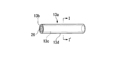
毛束13は複数本の用毛13aを束ねて構成される。本実施形態における用毛13aは、図3および図4に示すように、断面形状が円形で、端面13bが単一平面とされたストレート毛である。用毛13aの端面13bが単一平面である場合には、歯面の洗浄に適している。
また、本実施形態における用毛13aは、その中心に配置された1本の円柱状の導電性の芯部13cと、芯部13cの周面に、芯部13cと同心円状に設けられた非導電性の被覆部13dとを備えた芯鞘構造の用毛のである。図5に示すように、用毛13aの先端(即ち、毛先)の端面13bにおいては、芯部13cが露出しており、芯部13cの露出によって口腔内側の電極(第1電極)が形成されている。すなわち、本発明における第1電極は、用毛の毛先において、用毛の非導電性の被覆部から露出した導電性の芯部によって構成されている。 用毛13aは、芯部13cが導電体12に電気的に接続されるように固定されている。 用毛13aの導電体12への固定方法としては、溶着または接着を適用することができる。
毛束13は複数本の用毛13aを束ねて構成される。本実施形態における用毛13aは、図3および図4に示すように、断面形状が円形で、端面13bが単一平面とされたストレート毛である。用毛13aの端面13bが単一平面である場合には、歯面の洗浄に適している。
また、本実施形態における用毛13aは、その中心に配置された1本の円柱状の導電性の芯部13cと、芯部13cの周面に、芯部13cと同心円状に設けられた非導電性の被覆部13dとを備えた芯鞘構造の用毛のである。図5に示すように、用毛13aの先端(即ち、毛先)の端面13bにおいては、芯部13cが露出しており、芯部13cの露出によって口腔内側の電極(第1電極)が形成されている。すなわち、本発明における第1電極は、用毛の毛先において、用毛の非導電性の被覆部から露出した導電性の芯部によって構成されている。 用毛13aは、芯部13cが導電体12に電気的に接続されるように固定されている。 用毛13aの導電体12への固定方法としては、溶着または接着を適用することができる。
芯部13cは、導電性物質を含有することによって構成されている。本発明における「導電性」とは、体積抵抗率が1.0×10⁵Ω・cm以下のことであり、好ましくは1.0×10⁴Ω・cm以下、より好ましくは1.0×10³Ω・cm以下のことである。 導電性物質としては、例えば、金、銀等の金属;酸化チタン、酸化亜鉛等の金属酸化物;カーボンブラック等の炭素材料が挙げられる。これらの中でも、口腔内で使用される点および安定性の点から、炭素材料が好ましく、カーボンブラックがより好ましい。
上記導電性物質は、1種類の導電性物質を単独で使用してもよいし、2種類以上の導電性物質を適宜組み合わせて使用してもよい。
導電性物質の形状としては、粉末、粒状等、バインダ樹脂に均一に練り込むことができる形状であればよい。 また、芯部13cにおいては、導電性物質の他にバインダ樹脂を含有することが好ましい。バインダ樹脂としては、例えば、ポリエチレンテレフタレート(PET)、ポリブチレンテレフタレート(PBT)、ポリトリメチレンテレフタレート(PTT)等のポリエステル;ナイロン6、ナイロン66、ナイロン6-10、ナイロン6-12、ナイロン12等のポリアミド;ポリエチレン、ポリプロピレン等のポリオレフィン;ポリフッ化ビニリデン等のポリハロゲン化ビニル等が挙げられる。
芯部13cがバインダ樹脂を含有する場合、芯部13cを構成する全構成成分の合計量に対して、導電性物質の含有量は10~60質量%であることが好ましく、20~50質量%であることがより好ましい。導電性物質の含有量が前記下限値以上であれば、充分な導電性を得ることができ、前記上限値以下であれば、充分な強度を確保できる。
上記導電性物質は、1種類の導電性物質を単独で使用してもよいし、2種類以上の導電性物質を適宜組み合わせて使用してもよい。
導電性物質の形状としては、粉末、粒状等、バインダ樹脂に均一に練り込むことができる形状であればよい。 また、芯部13cにおいては、導電性物質の他にバインダ樹脂を含有することが好ましい。バインダ樹脂としては、例えば、ポリエチレンテレフタレート(PET)、ポリブチレンテレフタレート(PBT)、ポリトリメチレンテレフタレート(PTT)等のポリエステル;ナイロン6、ナイロン66、ナイロン6-10、ナイロン6-12、ナイロン12等のポリアミド;ポリエチレン、ポリプロピレン等のポリオレフィン;ポリフッ化ビニリデン等のポリハロゲン化ビニル等が挙げられる。
芯部13cがバインダ樹脂を含有する場合、芯部13cを構成する全構成成分の合計量に対して、導電性物質の含有量は10~60質量%であることが好ましく、20~50質量%であることがより好ましい。導電性物質の含有量が前記下限値以上であれば、充分な導電性を得ることができ、前記上限値以下であれば、充分な強度を確保できる。
被覆部13dは、芯部13cの周面を被覆して用毛13aの周面を絶縁化する部位であり、非導電性物質によって構成されている。本発明における「非導電性」とは、体積抵抗率が1.0×10¹²Ω・cm以上のことであり、好ましくは1.0×10¹⁴Ω・cm以上、より好ましくは1.0×10¹⁵Ω・cm以上のことである。
非導電性物質としては、非導電性の熱可塑性樹脂を使用することができる。非導電性の熱可塑性樹脂としては特に限定されず、例えば、上記バインダ樹脂と同様の樹脂を使用することができる。また、バインダ樹脂と同一であってもよいし、異なってもよい。
被覆部13dの厚みは、5μm以上が好ましい。被覆部13dの厚みが5μm未満の場合、均一に紡糸することができず、層の強度が確保できない。被覆部13dの厚みが5μm以上であれば、充分な絶縁性を確保できる。
なお、ここでいう「被覆部13dの厚み」とは、例えば、図4に示した断面図において用毛の最外層(被覆部13dの最外部)から用毛中心部を結んだ線のうち、最外部から被覆部13dと芯部13cとの境界面までの距離を意味する。
また、被覆部13dの厚みは、用毛の断面を拡大投影機やマイクロスコープ等を用いて拡大し、計測することができる。
非導電性物質としては、非導電性の熱可塑性樹脂を使用することができる。非導電性の熱可塑性樹脂としては特に限定されず、例えば、上記バインダ樹脂と同様の樹脂を使用することができる。また、バインダ樹脂と同一であってもよいし、異なってもよい。
被覆部13dの厚みは、5μm以上が好ましい。被覆部13dの厚みが5μm未満の場合、均一に紡糸することができず、層の強度が確保できない。被覆部13dの厚みが5μm以上であれば、充分な絶縁性を確保できる。
なお、ここでいう「被覆部13dの厚み」とは、例えば、図4に示した断面図において用毛の最外層(被覆部13dの最外部)から用毛中心部を結んだ線のうち、最外部から被覆部13dと芯部13cとの境界面までの距離を意味する。
また、被覆部13dの厚みは、用毛の断面を拡大投影機やマイクロスコープ等を用いて拡大し、計測することができる。
用毛13aの断面における芯部13cと被覆部13dの面積の比率(芯部13cの断面積/被覆部13dの断面積)は、20/80~70/30であることが好ましく、30/70~60/40であることがより好ましい。用毛13aの断面における芯部13cの面積の比率が大きすぎると、第1電極以外において芯部13cを被覆部13dにより絶縁できないことがあり、用毛13aの断面における被覆部13dの面積の比率が大きすぎると、芯部13cに電流を充分に流すことができないことがある。
用毛13aの太さは、3~10mil(0.076~0.254mm)が好ましく、5~8mil(0.125~0.203mm)がより好ましい。用毛13aの太さが前記下限値以上であれば、自立性が向上して清掃性がより高くなり、前記上限値以下であれば、毛束13の毛腰が適度になり、当たり心地がより良好になる。
また、用毛13aは、複数本の用毛全てが同じ太さであってもよいし、使用性、刷掃感、清掃効果、耐久性等を考慮して、2種以上の異なる太さの用毛13aが組み合わされてもよい。
2種以上の異なる太さの用毛が組み合わされる例としては、例えば、歯ブラシヘッド部の先端側に8milの用毛を用い、歯ブラシヘッド部の他の部位に7milの用毛を用いる組み合わせが挙げられる。これにより、奥歯の汚れに対する掻き取り力を上げることができる。また、歯ブラシヘッド部の外周部に6milの用毛を用い、歯ブラシヘッド部の中央部に7milの用毛を用いる組み合わせが挙げられる。これにより、歯ぐきへの当たりを柔らかくすることができる。
また、用毛13aは、複数本の用毛全てが同じ太さであってもよいし、使用性、刷掃感、清掃効果、耐久性等を考慮して、2種以上の異なる太さの用毛13aが組み合わされてもよい。
2種以上の異なる太さの用毛が組み合わされる例としては、例えば、歯ブラシヘッド部の先端側に8milの用毛を用い、歯ブラシヘッド部の他の部位に7milの用毛を用いる組み合わせが挙げられる。これにより、奥歯の汚れに対する掻き取り力を上げることができる。また、歯ブラシヘッド部の外周部に6milの用毛を用い、歯ブラシヘッド部の中央部に7milの用毛を用いる組み合わせが挙げられる。これにより、歯ぐきへの当たりを柔らかくすることができる。
用毛13aの製造方法としては、共押出成形機を用いた溶融紡糸によって製造する方法が挙げられる。具体的には、第1押出機によって芯部13c形成用の樹脂を溶融し、第2押出機によって被覆部13d用の樹脂を溶融し、ダイから芯部13c形成用の樹脂と被覆部13d形成用樹脂とを同時に吐出した後、延伸することにより、用毛13aを製造することができる。
(ハンドル部)
ハンドル部20は、円筒状のハンドル部本体21と、ハンドル部本体21の基端側の周面の一部に露出して設けられた第2電極22とを有する。
ここで、「ハンドル部本体21の基端」とは、ヘッド部本体との接続部とは反対側の端を意味する。
また、ハンドル部本体21の内部には、電源である電池Aを収容可能な空洞が形成され、さらに、電池Aの一方の極が接触する第1端子23と、電池Aの他方の極が接触する第2端子24と、配線25とが内蔵されている。第1端子23は、配線25を介して第2電極22に接続され、第2端子24は導電体12と接続されている。即ち、芯部13cは導電体12及び第2端子を介して電源に接続されている。 ハンドル部本体21の材質としては、ヘッド部本体11を構成する樹脂と同様の樹脂を使用することができる。また、ハンドル部本体21は、把持性を向上させるため、例えばエラストマー等の柔軟な樹脂が部分的に被覆されていてもよい。
第2電極22、第1端子23および第2端子24の材質としては、ヘッド部10の内部に設けられた導電体12を構成する材料と同様の材料を使用することができる。
電源としては、一次電池や二次電池を使用することができ、供給電圧として1.5V~12V程度あればよい。
ハンドル部20は、円筒状のハンドル部本体21と、ハンドル部本体21の基端側の周面の一部に露出して設けられた第2電極22とを有する。
ここで、「ハンドル部本体21の基端」とは、ヘッド部本体との接続部とは反対側の端を意味する。
また、ハンドル部本体21の内部には、電源である電池Aを収容可能な空洞が形成され、さらに、電池Aの一方の極が接触する第1端子23と、電池Aの他方の極が接触する第2端子24と、配線25とが内蔵されている。第1端子23は、配線25を介して第2電極22に接続され、第2端子24は導電体12と接続されている。即ち、芯部13cは導電体12及び第2端子を介して電源に接続されている。 ハンドル部本体21の材質としては、ヘッド部本体11を構成する樹脂と同様の樹脂を使用することができる。また、ハンドル部本体21は、把持性を向上させるため、例えばエラストマー等の柔軟な樹脂が部分的に被覆されていてもよい。
第2電極22、第1端子23および第2端子24の材質としては、ヘッド部10の内部に設けられた導電体12を構成する材料と同様の材料を使用することができる。
電源としては、一次電池や二次電池を使用することができ、供給電圧として1.5V~12V程度あればよい。
(製造方法)
本実施形態における口腔内用イオンブラシ1の製造方法としては特に制限されず、例えば、以下の(a)および(b)の方法が挙げられる。
(a)束ねた用毛13aを所定の植毛本数、毛束形状、および毛先形状に整えた後、毛先とは反対側の基端部を熱等の手段で溶融し、それにより形成した溶融塊を導電体12に接触させて溶着させると共に成形金型のキャビティ内に固定する。次いで、インモールド法によりヘッド部本体11とハンドル部本体21とを成形し、その後、第2電極22、第1端子23および第2端子24を取り付ける。
(b)複数本の用毛13aを束ねた毛束13を保持する毛束保持孔を設けた金型のキャビティに毛束13を挿入し、毛束13の基端部を熱等の手段で溶融して溶融塊を形成する。次いで、溶融塊が露出した状態で金型内に樹脂を充填して、毛束13が植毛された植毛部カセットを形成する。次いで、植毛部カセットとは別に、導電体12が取り付けられたヘッド部本体11およびハンドル部本体21を作製する。次いで、導電体12に植毛部カセットの溶融塊を接触させ、固定した後、超音波溶着、高周波溶着、レーザー溶着等の溶着手段により溶着する。その後、第2電極22、第1端子23および第2端子24を取り付ける。
本実施形態における口腔内用イオンブラシ1の製造方法としては特に制限されず、例えば、以下の(a)および(b)の方法が挙げられる。
(a)束ねた用毛13aを所定の植毛本数、毛束形状、および毛先形状に整えた後、毛先とは反対側の基端部を熱等の手段で溶融し、それにより形成した溶融塊を導電体12に接触させて溶着させると共に成形金型のキャビティ内に固定する。次いで、インモールド法によりヘッド部本体11とハンドル部本体21とを成形し、その後、第2電極22、第1端子23および第2端子24を取り付ける。
(b)複数本の用毛13aを束ねた毛束13を保持する毛束保持孔を設けた金型のキャビティに毛束13を挿入し、毛束13の基端部を熱等の手段で溶融して溶融塊を形成する。次いで、溶融塊が露出した状態で金型内に樹脂を充填して、毛束13が植毛された植毛部カセットを形成する。次いで、植毛部カセットとは別に、導電体12が取り付けられたヘッド部本体11およびハンドル部本体21を作製する。次いで、導電体12に植毛部カセットの溶融塊を接触させ、固定した後、超音波溶着、高周波溶着、レーザー溶着等の溶着手段により溶着する。その後、第2電極22、第1端子23および第2端子24を取り付ける。
(使用方法)
口腔内用イオンブラシ1の使用方法の一例について説明する。
使用者は、ハンドル部20を握り、第2電極22に手を接触させ、次いで、ヘッド部10を口腔内に挿入して、用毛13aの先端にて露出した芯部13cを口腔内組織(歯面、歯間等)に接触させる。これにより、口腔内組織と芯部13cとを電気的に導通させて、電池Aの一方の極、第1端子23、配線25、第2電極22、使用者の手、身体、口腔内組織、用毛13aの芯部13c、導電体12、第2端子24、電池の他方の極という経路で電流を流す。そして、歯面や歯間をブラッシングして洗浄する。なお、電流の向きは、目的とする効果や、後述するように口腔内用の有効成分を使用する場合にはその種類に応じて適宜選択すればよい。
口腔内用イオンブラシ1の使用時には、体内に数μA~数十μA程度の微弱な電流が流れると考えられるが、安全上の問題は生じない。むしろ、歯茎に微弱な電流が流れるため、歯茎の血行を促進でき、歯茎組織の活性化作用を奏する。
口腔内用イオンブラシ1の使用方法の一例について説明する。
使用者は、ハンドル部20を握り、第2電極22に手を接触させ、次いで、ヘッド部10を口腔内に挿入して、用毛13aの先端にて露出した芯部13cを口腔内組織(歯面、歯間等)に接触させる。これにより、口腔内組織と芯部13cとを電気的に導通させて、電池Aの一方の極、第1端子23、配線25、第2電極22、使用者の手、身体、口腔内組織、用毛13aの芯部13c、導電体12、第2端子24、電池の他方の極という経路で電流を流す。そして、歯面や歯間をブラッシングして洗浄する。なお、電流の向きは、目的とする効果や、後述するように口腔内用の有効成分を使用する場合にはその種類に応じて適宜選択すればよい。
口腔内用イオンブラシ1の使用時には、体内に数μA~数十μA程度の微弱な電流が流れると考えられるが、安全上の問題は生じない。むしろ、歯茎に微弱な電流が流れるため、歯茎の血行を促進でき、歯茎組織の活性化作用を奏する。
口腔内用イオンブラシ1で口腔内を洗浄する際には、口腔内洗浄用の有効成分を使用してもよい。ここで、有効成分としては、歯質強化成分、殺菌成分、抗炎症成分、抗酸化成分等が挙げられ、口腔内でイオン化する有効成分が好ましく使用される。口腔内用イオンブラシ1による口腔内の洗浄では、口腔内に電流を流すため、イオン化する有効成分を用いれば、電気泳動の原理を利用して目標部位に容易に浸透させることができる。
歯質強化成分としては、フッ化ナトリウム、モノフルオロリン酸ナトリウム、フッ化スズ等のフッ素化合物が挙げられる。
殺菌成分としては、第4級アンモニウム塩系殺菌剤の塩化セチルピリジウム、塩化ベンザルコニウム、塩化ベンゼトニウム、塩化デカリニウム、ビグアナイド系殺菌剤のグルコン酸クロルヘキシジン等が挙げられる。
抗炎症成分としては、トラネキサム酸、イプシロンカプロン酸、β-グリチルリチン酸、グリチルリチン酸ジカリウム等が挙げられる。
抗酸化成分としては、アスコルビン酸、リン酸アスコルビルマグネシウム等のビタミンC誘導体が挙げられる。
殺菌成分としては、第4級アンモニウム塩系殺菌剤の塩化セチルピリジウム、塩化ベンザルコニウム、塩化ベンゼトニウム、塩化デカリニウム、ビグアナイド系殺菌剤のグルコン酸クロルヘキシジン等が挙げられる。
抗炎症成分としては、トラネキサム酸、イプシロンカプロン酸、β-グリチルリチン酸、グリチルリチン酸ジカリウム等が挙げられる。
抗酸化成分としては、アスコルビン酸、リン酸アスコルビルマグネシウム等のビタミンC誘導体が挙げられる。
本実施形態の口腔内用イオンブラシ1では、用毛13aの芯部13cが被覆部13dによって被覆されているため、被覆部で被覆された部分は絶縁化されている。また、用毛13aの毛先においては、端面13bにおける芯部13cが露出しており、この露出した部分が、口腔内側の電極(第1電極)となっている。そのため、口腔内において、用毛13aの端面13bが接触する部分のみに電流を流すことができる。
したがって、口腔内用イオンブラシ1の使用時には、目標部位以外の部位に電流が流れにくく、電気の使用効率が高い。
また、目標部位以外の部位に電流が流れにくいから、口腔内の洗浄に際してイオン化可能な有効成分を使用する場合には、有効成分を口腔内の目標部位に効率的に浸透させることができる。
したがって、口腔内用イオンブラシ1の使用時には、目標部位以外の部位に電流が流れにくく、電気の使用効率が高い。
また、目標部位以外の部位に電流が流れにくいから、口腔内の洗浄に際してイオン化可能な有効成分を使用する場合には、有効成分を口腔内の目標部位に効率的に浸透させることができる。
(他の実施形態)
なお、本発明は上記実施形態に限定されない。
歯ブラシ植毛部の毛切り形状(外観形状)は、単一平面状でなくてもよく、山切り形状であってもよいし、凹凸形状であってもよい。また、植毛部の外側と内側とで形状が異なってもよい。
また、用毛の先端面(即ち、毛先)と毛先とは反対側に位置する基端面とで形状が異なってもよく、例えば、図6に示すように、用毛13aの先端形状がテーパー状で、芯部13cと被覆部13dとにより構成された用毛であってもよい。用毛13aの先端形状がテーパー状である場合には、歯間の洗浄に適している。また、用毛の先端形状は、ヘラ状、スクレイパー状、球状等であってもよい。
用毛の長手方向に垂直な断面形状は、円形に限らず、楕円形;三角形、四角形等の多角形;星形等であってもよいし、三つ葉型、四つ葉型等直線同士、曲線同士、さらには直線と曲線を組み合わせた形状であってもよい。
ヘッド部における毛束の配列は、格子配列である必要はなく、千鳥配列や非対称な配列、その他どのような配列でもよい。ヘッド部の長手方向の軸線に対して毛束の配列が対称である必要もない。
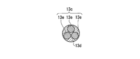
また、用毛は、芯鞘構造の用毛でなくてもよく、例えば、複数本のフィラメントからなる芯部が絶縁部により被覆された、断面が海島構造の用毛であってもよい。用毛が、複数本のフィラメントからなる芯部を備える形態の一例として、図7に、3本のフィラメント13eからなる芯部13cと、前記芯部13cの周面を被覆する被覆部13dとを備える用毛を示す。芯部13cが複数本のフィラメントからなる場合であっても、被覆部13dにより用毛13aの周面が絶縁化されているため、上記実施形態と同様の効果を奏する。
なお、本発明は上記実施形態に限定されない。
歯ブラシ植毛部の毛切り形状(外観形状)は、単一平面状でなくてもよく、山切り形状であってもよいし、凹凸形状であってもよい。また、植毛部の外側と内側とで形状が異なってもよい。
また、用毛の先端面(即ち、毛先)と毛先とは反対側に位置する基端面とで形状が異なってもよく、例えば、図6に示すように、用毛13aの先端形状がテーパー状で、芯部13cと被覆部13dとにより構成された用毛であってもよい。用毛13aの先端形状がテーパー状である場合には、歯間の洗浄に適している。また、用毛の先端形状は、ヘラ状、スクレイパー状、球状等であってもよい。
用毛の長手方向に垂直な断面形状は、円形に限らず、楕円形;三角形、四角形等の多角形;星形等であってもよいし、三つ葉型、四つ葉型等直線同士、曲線同士、さらには直線と曲線を組み合わせた形状であってもよい。
ヘッド部における毛束の配列は、格子配列である必要はなく、千鳥配列や非対称な配列、その他どのような配列でもよい。ヘッド部の長手方向の軸線に対して毛束の配列が対称である必要もない。
また、用毛は、芯鞘構造の用毛でなくてもよく、例えば、複数本のフィラメントからなる芯部が絶縁部により被覆された、断面が海島構造の用毛であってもよい。用毛が、複数本のフィラメントからなる芯部を備える形態の一例として、図7に、3本のフィラメント13eからなる芯部13cと、前記芯部13cの周面を被覆する被覆部13dとを備える用毛を示す。芯部13cが複数本のフィラメントからなる場合であっても、被覆部13dにより用毛13aの周面が絶縁化されているため、上記実施形態と同様の効果を奏する。
また、ハンドル部本体は円筒状、すなわち、長手方向に垂直な断面が円形でなくてもよく、例えば、楕円形であってもよいし、断面が多角形(三角形、四角形、五角形、六角形等)であってもよい。
また、第2電極は、ハンドル部本体21の基端側に設けられていなくてもよく、口腔内用イオン歯ブラシ使用時に使用者の手が接触する部分であれば特に制限はされない。
また、導電体および第2電極の形状によっては、第1端子、第2端子および配線を省略してもよい。
また、電源として、電池の代わりに外部電源を用いても構わない。
外部電源としては、大容量の電池を外部に設け、接続線等で口腔内イオンブラシへ電源供給してもよいし、家庭用AC電源を、抵抗器を用いて1.5V~12Vに降圧して用いてもよい。
また、第2電極は、ハンドル部本体21の基端側に設けられていなくてもよく、口腔内用イオン歯ブラシ使用時に使用者の手が接触する部分であれば特に制限はされない。
また、導電体および第2電極の形状によっては、第1端子、第2端子および配線を省略してもよい。
また、電源として、電池の代わりに外部電源を用いても構わない。
外部電源としては、大容量の電池を外部に設け、接続線等で口腔内イオンブラシへ電源供給してもよいし、家庭用AC電源を、抵抗器を用いて1.5V~12Vに降圧して用いてもよい。
また、本発明の口腔内用イオンブラシは歯ブラシ型でなくてもよく、歯間ブラシ型でもよい。歯間ブラシ型イオンブラシは、例えば、以下の製造方法で製造される。
すなわち、まず、折り返したワイヤに芯部を形成する導電性のフィラメントを挟み込むと共に、ワイヤを捻り合わせて、導電性のフィラメントを固定した後、全体を非導電性物質でコーティングする。これにより、導電性フィラメントからなる芯部の外側に被覆部を形成した用毛を得ると共にヘッド部を形成する。この時点では、芯部の先端は露出していないので、用毛の先端を切断して芯部を露出させて第1電極を形成する。次いで、射出成形によるインサート成形により、ハンドル部を成形すると共にワイヤの基端をハンドル部に接続する。その後、第2電極、第1端子および第2端子を取り付けて、歯間ブラシ型イオンブラシを得る。
すなわち、まず、折り返したワイヤに芯部を形成する導電性のフィラメントを挟み込むと共に、ワイヤを捻り合わせて、導電性のフィラメントを固定した後、全体を非導電性物質でコーティングする。これにより、導電性フィラメントからなる芯部の外側に被覆部を形成した用毛を得ると共にヘッド部を形成する。この時点では、芯部の先端は露出していないので、用毛の先端を切断して芯部を露出させて第1電極を形成する。次いで、射出成形によるインサート成形により、ハンドル部を成形すると共にワイヤの基端をハンドル部に接続する。その後、第2電極、第1端子および第2端子を取り付けて、歯間ブラシ型イオンブラシを得る。
本発明の口腔内用イオンブラシは、電気の使用効率が高く、また、イオン化可能な有効成分を用いる場合には、有効成分を口腔内の目標部位に効率的に浸透させることができるので、産業上極めて有用である。
1 口腔内用イオンブラシ
10 ヘッド部
11 ヘッド部本体
11a 植毛面
12 導電体
13 毛束
13a 用毛
13b 端面
13c 芯部
13d 被覆部
20 ハンドル部
21 ハンドル部本体
22 第2電極
23 第1端子
24 第2端子
25 配線
26 第1電極
A 電池(電源)
10 ヘッド部
11 ヘッド部本体
11a 植毛面
12 導電体
13 毛束
13a 用毛
13b 端面
13c 芯部
13d 被覆部
20 ハンドル部
21 ハンドル部本体
22 第2電極
23 第1端子
24 第2端子
25 配線
26 第1電極
A 電池(電源)
Claims (1)
- 導電性の芯部と前記芯部の周面を被覆する非導電性の被覆部とを備える用毛が植設されたヘッド部と、前記ヘッド部に延設されたハンドル部とを備え、
前記芯部は電源に接続され、
前記用毛の先端には、前記芯部が露出した第1電極が形成され、前記ハンドル部には、電源が接続された第2電極が露出して形成されている口腔内用イオンブラシ。
Priority Applications (2)
| Application Number | Priority Date | Filing Date | Title |
|---|---|---|---|
| CN201280059965.7A CN103987295B (zh) | 2011-12-06 | 2012-12-04 | 口腔内用离子刷 |
| KR1020147012216A KR20140108632A (ko) | 2011-12-06 | 2012-12-04 | 구강내용 이온 브러시 |
Applications Claiming Priority (2)
| Application Number | Priority Date | Filing Date | Title |
|---|---|---|---|
| JP2011266851A JP2013118895A (ja) | 2011-12-06 | 2011-12-06 | 口腔内用イオンブラシ |
| JP2011-266851 | 2011-12-06 |
Publications (1)
| Publication Number | Publication Date |
|---|---|
| WO2013084863A1 true WO2013084863A1 (ja) | 2013-06-13 |
Family
ID=48574230
Family Applications (1)
| Application Number | Title | Priority Date | Filing Date |
|---|---|---|---|
| PCT/JP2012/081335 Ceased WO2013084863A1 (ja) | 2011-12-06 | 2012-12-04 | 口腔内用イオンブラシ |
Country Status (4)
| Country | Link |
|---|---|
| JP (1) | JP2013118895A (ja) |
| KR (1) | KR20140108632A (ja) |
| CN (1) | CN103987295B (ja) |
| WO (1) | WO2013084863A1 (ja) |
Cited By (7)
| Publication number | Priority date | Publication date | Assignee | Title |
|---|---|---|---|---|
| WO2015085536A1 (en) * | 2013-12-12 | 2015-06-18 | Colgate-Palmolive Company | Multi-component bristle having components with different oral care additives, and oral care implement comprising the same |
| WO2018044754A1 (en) * | 2016-09-01 | 2018-03-08 | Colgate-Palmolive Company | Oral care implement and filament therefor |
| US10702057B2 (en) | 2015-07-07 | 2020-07-07 | Colgate-Palmolive Company | Oral care implement and monofilament bristle for use with the same |
| US20210169624A1 (en) * | 2015-12-30 | 2021-06-10 | Colgate-Palmolive Company | Oral Care Device with Sacrificial Electrode |
| US20220395087A1 (en) * | 2019-11-11 | 2022-12-15 | Proxihealthcare Inc. | Toothbrush for promoting plaque removal and manufacturing method therefor |
| CN116744822A (zh) * | 2020-12-22 | 2023-09-12 | 皇家飞利浦有限公司 | 用于口腔护理装置的清洁和/或处理单元 |
| AU2022263452B2 (en) * | 2017-06-27 | 2024-01-25 | Colgate-Palmolive Company | Oral care implement |
Families Citing this family (1)
| Publication number | Priority date | Publication date | Assignee | Title |
|---|---|---|---|---|
| JP2017042550A (ja) * | 2015-08-28 | 2017-03-02 | ライオン株式会社 | 口腔内清掃用具 |
Citations (1)
| Publication number | Priority date | Publication date | Assignee | Title |
|---|---|---|---|---|
| WO2011078127A1 (ja) * | 2009-12-22 | 2011-06-30 | パナソニック電工 株式会社 | ブラシ体及び歯ブラシ |
Family Cites Families (6)
| Publication number | Priority date | Publication date | Assignee | Title |
|---|---|---|---|---|
| JPS53111859A (en) * | 1977-03-10 | 1978-09-29 | Takeshi Okamoto | Toothhbrush with electrode |
| JP2000287755A (ja) * | 1999-04-09 | 2000-10-17 | Lion Corp | ブラシ製品の製造方法 |
| JP4862242B2 (ja) * | 2001-09-28 | 2012-01-25 | サンスター株式会社 | 歯ブラシの製造方法 |
| JP2008154888A (ja) * | 2006-12-26 | 2008-07-10 | Lion Corp | 歯刷子用刷毛及びそれを用いた歯刷子、並びに歯刷子用刷毛の製造方法 |
| JP2010124904A (ja) * | 2008-11-25 | 2010-06-10 | Panasonic Electric Works Co Ltd | 口腔ケア装置 |
| JP5292346B2 (ja) * | 2010-03-25 | 2013-09-18 | パナソニック株式会社 | ブラシ体および歯ブラシ |
-
2011
- 2011-12-06 JP JP2011266851A patent/JP2013118895A/ja active Pending
-
2012
- 2012-12-04 CN CN201280059965.7A patent/CN103987295B/zh not_active Expired - Fee Related
- 2012-12-04 KR KR1020147012216A patent/KR20140108632A/ko not_active Ceased
- 2012-12-04 WO PCT/JP2012/081335 patent/WO2013084863A1/ja not_active Ceased
Patent Citations (1)
| Publication number | Priority date | Publication date | Assignee | Title |
|---|---|---|---|---|
| WO2011078127A1 (ja) * | 2009-12-22 | 2011-06-30 | パナソニック電工 株式会社 | ブラシ体及び歯ブラシ |
Cited By (13)
| Publication number | Priority date | Publication date | Assignee | Title |
|---|---|---|---|---|
| US10299580B2 (en) | 2013-12-12 | 2019-05-28 | Colgate-Palmolive Company | Multi-component bristle having components with different oral care additives, and oral care implement comprising the same |
| WO2015085536A1 (en) * | 2013-12-12 | 2015-06-18 | Colgate-Palmolive Company | Multi-component bristle having components with different oral care additives, and oral care implement comprising the same |
| US10702057B2 (en) | 2015-07-07 | 2020-07-07 | Colgate-Palmolive Company | Oral care implement and monofilament bristle for use with the same |
| US12251284B2 (en) * | 2015-12-30 | 2025-03-18 | Colgate-Palmolive Company | Oral care device with sacrificial electrode |
| US20210169624A1 (en) * | 2015-12-30 | 2021-06-10 | Colgate-Palmolive Company | Oral Care Device with Sacrificial Electrode |
| EP3487356A1 (en) * | 2016-09-01 | 2019-05-29 | Colgate-Palmolive Company | Oral care implement and filament therefor |
| AU2017319133B2 (en) * | 2016-09-01 | 2019-10-31 | Colgate-Palmolive Company | Oral care implement and filament therefor |
| US11103056B2 (en) | 2016-09-01 | 2021-08-31 | Colgate-Palmolive Company | Oral care implement and filament therefor |
| WO2018044754A1 (en) * | 2016-09-01 | 2018-03-08 | Colgate-Palmolive Company | Oral care implement and filament therefor |
| AU2022263452B2 (en) * | 2017-06-27 | 2024-01-25 | Colgate-Palmolive Company | Oral care implement |
| US20220395087A1 (en) * | 2019-11-11 | 2022-12-15 | Proxihealthcare Inc. | Toothbrush for promoting plaque removal and manufacturing method therefor |
| US12433395B2 (en) * | 2019-11-11 | 2025-10-07 | Proxihealthcare Inc. | Toothbrush for promoting plaque removal and manufacturing method therefor |
| CN116744822A (zh) * | 2020-12-22 | 2023-09-12 | 皇家飞利浦有限公司 | 用于口腔护理装置的清洁和/或处理单元 |
Also Published As
| Publication number | Publication date |
|---|---|
| CN103987295A (zh) | 2014-08-13 |
| CN103987295B (zh) | 2016-01-20 |
| KR20140108632A (ko) | 2014-09-12 |
| JP2013118895A (ja) | 2013-06-17 |
Similar Documents
| Publication | Publication Date | Title |
|---|---|---|
| WO2013084863A1 (ja) | 口腔内用イオンブラシ | |
| EP2394530B1 (en) | Brush body, method of its manufacture and toothbrush including this brush body | |
| EP1955730B1 (en) | Oral care device | |
| TWI421043B (zh) | toothbrush | |
| KR101646874B1 (ko) | 플라즈마 칫솔 | |
| JP5292346B2 (ja) | ブラシ体および歯ブラシ | |
| US20120233791A1 (en) | Brush body and toothbrush | |
| US20120233790A1 (en) | Brush body and toothbrush | |
| CN114650749B (zh) | 用于促进牙菌斑去除的牙刷及其制造方法 | |
| JPS63288102A (ja) | 口腔疾患治療用のマイクロエレクトロニクス・イオン化装置 | |
| EP2120776A2 (en) | Iontophoresis and active dental applicances | |
| US20190380482A1 (en) | Oral care device and attachment | |
| JP6621497B2 (ja) | 歯ブラシ | |
| JP2004208816A (ja) | 歯ブラシ | |
| WO2012063565A1 (ja) | 電動歯ブラシおよびそのブラシ体、並びにその製造方法 | |
| JPH1042962A (ja) | イオン歯ブラシ | |
| JPH0744887B2 (ja) | 磁気イオン歯ブラシ | |
| JP4372537B2 (ja) | 口腔清掃用具 | |
| JPH06217830A (ja) | イオン歯ブラシ | |
| JP2014050640A (ja) | 歯ブラシ | |
| JP2012000149A (ja) | 通電歯茎マッサージ用ブラシ | |
| WO2012086322A1 (ja) | ブラシ体、歯ブラシ、およびブラシ体の製造方法 | |
| JPH0628016Y2 (ja) | 歯刷子 | |
| JP2023176395A (ja) | 動物用歯磨きセット | |
| JPH08266337A (ja) | 歯間ブラシ |
Legal Events
| Date | Code | Title | Description |
|---|---|---|---|
| 121 | Ep: the epo has been informed by wipo that ep was designated in this application |
Ref document number: 12854860 Country of ref document: EP Kind code of ref document: A1 |
|
| ENP | Entry into the national phase |
Ref document number: 20147012216 Country of ref document: KR Kind code of ref document: A |
|
| NENP | Non-entry into the national phase |
Ref country code: DE |
|
| 122 | Ep: pct application non-entry in european phase |
Ref document number: 12854860 Country of ref document: EP Kind code of ref document: A1 |