WO2013084830A1 - 熱音響機関 - Google Patents
熱音響機関 Download PDFInfo
- Publication number
- WO2013084830A1 WO2013084830A1 PCT/JP2012/081193 JP2012081193W WO2013084830A1 WO 2013084830 A1 WO2013084830 A1 WO 2013084830A1 JP 2012081193 W JP2012081193 W JP 2012081193W WO 2013084830 A1 WO2013084830 A1 WO 2013084830A1
- Authority
- WO
- WIPO (PCT)
- Prior art keywords
- regenerator
- resonance
- pipe
- heat
- thermoacoustic engine
- Prior art date
- Legal status (The legal status is an assumption and is not a legal conclusion. Google has not performed a legal analysis and makes no representation as to the accuracy of the status listed.)
- Ceased
Links
Images


Classifications
-
- F—MECHANICAL ENGINEERING; LIGHTING; HEATING; WEAPONS; BLASTING
- F25—REFRIGERATION OR COOLING; COMBINED HEATING AND REFRIGERATION SYSTEMS; HEAT PUMP SYSTEMS; MANUFACTURE OR STORAGE OF ICE; LIQUEFACTION SOLIDIFICATION OF GASES
- F25B—REFRIGERATION MACHINES, PLANTS OR SYSTEMS; COMBINED HEATING AND REFRIGERATION SYSTEMS; HEAT PUMP SYSTEMS
- F25B9/00—Compression machines, plants or systems, in which the refrigerant is air or other gas of low boiling point
- F25B9/14—Compression machines, plants or systems, in which the refrigerant is air or other gas of low boiling point characterised by the cycle used, e.g. Stirling cycle
- F25B9/145—Compression machines, plants or systems, in which the refrigerant is air or other gas of low boiling point characterised by the cycle used, e.g. Stirling cycle pulse-tube cycle
-
- F—MECHANICAL ENGINEERING; LIGHTING; HEATING; WEAPONS; BLASTING
- F02—COMBUSTION ENGINES; HOT-GAS OR COMBUSTION-PRODUCT ENGINE PLANTS
- F02G—HOT GAS OR COMBUSTION-PRODUCT POSITIVE-DISPLACEMENT ENGINE PLANTS; USE OF WASTE HEAT OF COMBUSTION ENGINES; NOT OTHERWISE PROVIDED FOR
- F02G1/00—Hot gas positive-displacement engine plants
- F02G1/04—Hot gas positive-displacement engine plants of closed-cycle type
- F02G1/043—Hot gas positive-displacement engine plants of closed-cycle type the engine being operated by expansion and contraction of a mass of working gas which is heated and cooled in one of a plurality of constantly communicating expansible chambers, e.g. Stirling cycle type engines
-
- F—MECHANICAL ENGINEERING; LIGHTING; HEATING; WEAPONS; BLASTING
- F03—MACHINES OR ENGINES FOR LIQUIDS; WIND, SPRING, OR WEIGHT MOTORS; PRODUCING MECHANICAL POWER OR A REACTIVE PROPULSIVE THRUST, NOT OTHERWISE PROVIDED FOR
- F03G—SPRING, WEIGHT, INERTIA OR LIKE MOTORS; MECHANICAL-POWER PRODUCING DEVICES OR MECHANISMS, NOT OTHERWISE PROVIDED FOR OR USING ENERGY SOURCES NOT OTHERWISE PROVIDED FOR
- F03G7/00—Mechanical-power-producing mechanisms, not otherwise provided for or using energy sources not otherwise provided for
- F03G7/002—Mechanical-power-producing mechanisms, not otherwise provided for or using energy sources not otherwise provided for using the energy of vibration of fluid columns
-
- F—MECHANICAL ENGINEERING; LIGHTING; HEATING; WEAPONS; BLASTING
- F25—REFRIGERATION OR COOLING; COMBINED HEATING AND REFRIGERATION SYSTEMS; HEAT PUMP SYSTEMS; MANUFACTURE OR STORAGE OF ICE; LIQUEFACTION SOLIDIFICATION OF GASES
- F25B—REFRIGERATION MACHINES, PLANTS OR SYSTEMS; COMBINED HEATING AND REFRIGERATION SYSTEMS; HEAT PUMP SYSTEMS
- F25B2309/00—Gas cycle refrigeration machines
- F25B2309/14—Compression machines, plants or systems characterised by the cycle used
- F25B2309/1403—Pulse-tube cycles with heat input into acoustic driver
Definitions
- the present invention relates to a thermoacoustic engine that generates self-excited vibration of a working gas.
- thermoacoustic engines have been actively conducted in order to recover these energies and drive them.
- thermoacoustic engine uses self-excited vibration generated in the pipe. That is, when a bundle of narrow flow paths (hereinafter referred to as a heat accumulator) is installed in the pipe and the temperature ratio at both ends of the heat accumulator is set to a certain critical value or more, the fluid in the pipe causes self-excited vibration.
- This action can be regarded thermodynamically as a prime mover having no moving parts, and a thermoacoustic engine using this action is disclosed in, for example, Patent Documents 1 and 2. Since the thermoacoustic engine is an external combustion engine driven by a Stirling cycle, there is a possibility that work can be extracted with high efficiency from any heat source such as sunlight and industrial waste heat.
- it since it has a simple configuration in which heat is exchanged using sound waves, unlike a normal Stirling engine, it does not require any moving parts such as a piston and a turbine, and has the advantages of low cost, long life, and maintenance-free.
- FIG. 10 shows a configuration of a typical thermoacoustic engine (for example, see Non-Patent Document 1) that has been studied for practical use in recent years.
- a thermoacoustic generator 500 shown in FIG. 10A includes a loop tube 100 and a resonance tube 111.
- the loop tube 100 includes a heat accumulator 210, a heater 220, and a cooler 230 that constitute the prime mover 200, and a generator (linear generator) 300 is provided at the tip of the resonance tube 111.
- thermoacoustic generator 500 when a temperature gradient is given to the regenerator 210, self-excited vibration that is a sound wave (that is, thermoacoustic self-excited vibration) is excited, and vibration energy (that is, acoustic energy) E of this sound wave is linearly generated.
- Machine 300 converts it into electric power.
- the thermoacoustic generator 500 is assumed to be used as a high-efficiency solar power generator that exceeds waste heat generators and solar panels.
- thermoacoustic refrigerator 600 includes two loop tubes 100 and 120 and a resonance tube 111.
- the loop pipe 100 includes a heat accumulator 210, a heater 220, and a cooler 230 that constitute the prime mover 200.
- the loop pipe 120 includes a refrigerating heat accumulator 410 that constitutes the refrigerator 400, and cool air discharge. 420 and a refrigeration cooler 430 are provided.
- a temperature gradient is applied to the regenerator 210 installed in one loop tube 100, self-excited vibration is excited.
- thermoacoustic refrigerator 600 that performs low-temperature generation using self-excited vibration that is such an in-tube acoustic wave has a potential that exceeds that of a pulse tube refrigerator.
- thermoacoustic engines represented above are currently being studied by many companies from the viewpoint of heat recovery and next-generation energy utilization. However, since this is a new field where full-fledged research has begun in the 21st century, there is a situation where basic technology has not yet been established.
- the operating temperature of a thermoacoustic engine that is generally attempted is about 500 ° C. (see Non-Patent Document 3), and compared with the waste heat temperature from an actual automobile or factory (about 100 ° C. to 300 ° C.). It is extremely hot.
- thermoacoustic engine realizes power amplification of the work flow W in each heat accumulator by arranging the heat accumulators in multiple stages in series.
- thermoacoustic engine the thermal efficiency is low at 10% or less because the heat accumulators are distributed with respect to the acoustic impedance distribution due to the property of “using a plurality of heat accumulators”. Moreover, although it has been confirmed that high efficiency can be realized at an operating temperature in a high temperature region of about 700 ° C., waste heat discharged from industrial facilities is generally a low temperature of 300 ° C. or less. Therefore, at present, there is no thermoacoustic engine having a thermal efficiency exceeding 10% by using a heat source temperature that is about the industrial waste heat.
- thermoacoustic engine that can realize high thermal efficiency in a low temperature region. If the structure of a thermoacoustic engine having a thermal efficiency exceeding 30% at an industrial waste heat temperature of about 300 ° C. is clarified, a high-efficiency thermal energy recovery system that is inexpensive, maintenance-free, and easy to mass-produce will be realized. become. The realization of such a thermoacoustic engine has a tremendous effect on the environment and economic energy savings, and it is possible to rapidly spread the thermoacoustic engine to the general public as a powerful next-generation device. it is conceivable that.
- the present invention has been made based on such a background, and an object of the present invention is to provide a thermoacoustic engine that can be driven at a low temperature and has high thermal efficiency.
- thermoacoustic engine performs energy conversion by isothermal and reversible heat exchange, so that ideally Carnot efficiency can be expected.
- external input or sound wave feedback is essential.
- Yazaki et al. Provided acoustic heat feedback by installing a regenerator in a torus-type loop, and demonstrated the first practical traveling-wave engine (T. Yazaki et.al., Phys. Rev. Lett 81, pp.3128-3131, 1988.).
- the dream pipe effect means the following items.
- the fluid in the container having a temperature gradient is forcibly vibrated by an external piston or the like, a very large heat flow is generated from the high temperature portion to the low temperature portion.
- the effective heat transport amount reaches 1000 times or more when there is no vibration.
- heat transport exceeding the thermal conductivity of the metal can be achieved only by vibrating the fluid.
- a thermoacoustic engine is used as the engine, heat transport to the low temperature side leads to a decrease in efficiency, so the dream pipe effect is a major factor that decreases the efficiency of the thermoacoustic engine.
- thermoacoustic engine with a branch resonance tube in the loop (S. Backhaus and G. W. Swift, J. Acoust. Soc. Am. 107, 6, .pp. 3148-3166, 2000.).
- the thermoacoustic engine proposed by Backhaus et al. Enables energy conversion using traveling waves due to the loop structure, and at the same time realizes resonance by a quarter wavelength and high acoustic impedance at the heat accumulator position by the branch pipe resonance tube. . Therefore, there is little viscous dissipation and dream pipe effect in the heat accumulator, and a high efficiency equivalent to a gasoline engine with a thermal efficiency of 30% is realized.
- this efficiency is the ratio of the input heat quantity and the work flow W output to the branch pipe resonance tube. Since the standing wave is dominant in the branch pipe resonance tube, the viscous dissipation is large, and the efficiency may be reduced in terms of energy transport.
- the operating temperature is as high as about 1000K. Therefore, in order to realize a practical thermoacoustic engine, it is necessary to achieve both low temperature operation and high efficiency.
- thermoacoustic engine in which heat accumulators are arranged in series has been proposed as an attempt to lower the operating temperature.
- Gardner et al. Succeeded in obtaining approximately 1 kW of output by amplifying the work flow W generated from a standing wave engine with a traveling wave engine installed at a high acoustic impedance position (DLGardner and GWSwift, J. Acoust. Soc. Am. 114, pp. 1905-1919, 2003.).
- We have achieved a critical oscillation temperature ratio of 1.19 by installing five regenerators in a loop thermoacoustic engine T.Biwa et al., Appl. Phys. Lett. 97, 034102, 2010). .).
- the multi-stage type has a characteristic that “a plurality of heat accumulators are used”, and thus the heat accumulators are distributed in a distributed manner with respect to the sound field. Therefore, in many cases, it is necessary to install a heat accumulator in addition to the high acoustic impedance portion, and generally the efficiency is often low.
- the present inventors have found a configuration that realizes energy conversion using traveling waves with high acoustic impedance at all the heat accumulator positions of the loop type multistage thermoacoustic engine.
- the present inventors have found a configuration that realizes a traveling wave having an acoustic impedance value of about ⁇ c ( ⁇ : gas density, c: speed of sound) at a position other than the heat accumulator, thereby reducing viscous dissipation in the resonance tube.
- thermoacoustic engine includes a plurality of resonance tubes in which a working gas is enclosed and formed in a ring shape as a whole, and a plurality of resonance tubes that connect the plurality of resonance tubes.
- a prime mover and a branch pipe having one end connected to the resonance pipe from an intersection of a start point and an end point of a loop forming an annular shape among the plurality of resonance pipes.
- the cross-sectional area of the resonance tube to be connected is determined by the prime mover provided with the heater. It is the same as the amplification factor of the work flow due to the self-excited vibration or the amplification factor within ⁇ 30% of the cross-sectional area of the resonance tube connected to the cooler.
- the flow passage cross-sectional area of the vessel is 4 to 36 times the flow passage cross-sectional area of the resonance tube connected to the cooler of the prime mover including the heat accumulator.
- one end of the regenerator is heated by the heater, and the other end of the regenerator is cooled by the cooler, so that a temperature difference, that is, a temperature gradient is generated between both ends of the regenerator. Arise. Due to this temperature difference, a work flow W is generated mainly due to self-excited vibration (pressure vibration) of the working gas. Then, the channel cross-sectional area of the resonance tube connected to the heater is the same as the amplification factor of the work flow W due to self-excited vibration or ⁇ 30% of the channel cross-sectional area of the resonance tube connected to the cooler.
- a traveling wave having an acoustic impedance value of about ⁇ c can be obtained at a position other than the heat accumulator. Further, by making the flow passage cross-sectional area of the heat accumulator 4 to 36 times the flow passage cross-sectional area of the resonance tube connected to the cooler, a traveling wave with high acoustic impedance can be obtained at all the heat accumulator positions.
- thermoacoustic engine further includes a generator that is connected to the other end of the branch pipe, communicates with the branch pipe, and generates power in response to self-excited vibration generated in the working gas.
- the thermoacoustic generator can be used. According to such a configuration, acoustic energy generated by the self-excited vibration generated in the working gas is converted into electric energy by the generator. And as a thermoacoustic generator, it can drive with low temperature and high efficiency.
- thermoacoustic engine further includes an annular refrigeration loop pipe connected in communication with the other end of the branch pipe, and is provided in a pipe line of the refrigeration loop pipe.
- one end of the refrigerating regenerator is cooled by the refrigerating cooler, and acoustic energy generated by the self-excited vibration generated in the working gas is transmitted to the refrigerating regenerator.
- the transmitted acoustic energy is converted into a temperature difference between one end of the refrigerating regenerator and the other end of the refrigerating regenerator.
- the cold air generated at the other end of the refrigerating regenerator due to the temperature difference between both ends of the refrigerating regenerator is taken out by the cold air discharger. And as a thermoacoustic refrigerator, it can drive with low temperature and high efficiency.
- thermoacoustic engine according to the present invention enables highly efficient energy conversion as compared with a conventional thermoacoustic engine. In addition, it can be driven at a lower temperature than a conventional thermoacoustic engine. Furthermore, a plurality of heat accumulators can be installed at the traveling wave phase position. And energy recovery using a plurality of waste heat sources becomes possible by installing a plurality of heat accumulators.
- the entire apparatus can be reduced in size, and the volume of the entire apparatus can be reduced.
- the amount of power generation can be improved compared to a conventional thermoacoustic engine, and when used as a thermoacoustic refrigerator, it can be heated at a lower temperature than a conventional thermoacoustic engine. It is possible to realize efficient driving.
- thermoacoustic engine It is a mimetic diagram showing typically the composition of the thermoacoustic engine concerning the present invention. It is a schematic diagram at the time of using the thermoacoustic engine which concerns on this invention as a thermoacoustic generator. It is a schematic diagram at the time of using the thermoacoustic engine which concerns on this invention as a thermoacoustic refrigerator. It is the schematic of the numerical calculation model about the thermoacoustic engine of this invention in an Example. It is a graph which shows acoustic impedance distribution in the numerical calculation model about the thermoacoustic engine used in the Example, (a) shows the real part of impedance, (b) shows the imaginary part of impedance.
- thermoacoustic engine 20b It is a graph which shows the phase difference between the pressure and the flow velocity in the numerical calculation model about the thermoacoustic engine used in the Example. It is a graph which shows the spatial distribution of the normalized work flow W in the numerical calculation model about the thermoacoustic engine used in the Example. It is a graph which shows the heat flow component of the regenerator in the numerical calculation model about the thermoacoustic engine used in the Example, (a) is the heat flow component of the regenerator of the motor 20a, (b) is the heat flow of the regenerator of the motor 20b. It is an ingredient.
- thermoacoustic engine it is a graph which shows the heat flow component of the regenerator in the numerical calculation model about the thermoacoustic engine used in the Example
- (c) is the heat flow component of the regenerator of the motor 20c
- (d) is the heat flow of the regenerator of the motor 20d. It is an ingredient.
- (a) is a schematic diagram at the time of using a thermoacoustic engine as a thermoacoustic generator
- thermoacoustic refrigeration It is a schematic diagram at the time of using as a machine.
- thermoacoustic engine 1 includes a plurality of resonance tubes 10a to 10f that are filled with a working gas and formed in an annular shape as a whole, and a plurality of prime movers 20 that connect the plurality of resonance tubes 10a to 10f. (20a to 20d) and a branch pipe (branch pipe resonance) having one end connected to the resonance pipe 10 from the intersection of the start point and the end point of the loop forming the ring among the plurality of resonance pipes 10a to 10f. Tube) 11.
- branch pipe branch pipe resonance
- the resonance tubes 10a to 10f are tubes filled with a working gas, and are formed in an annular shape as a whole. Here, it is composed of six resonance tubes 10a to 10f, and is connected via a prime mover 20 to form a ring, thereby forming an annular resonance tube 10. That is, the resonance tube 10b is arranged on the right side of the paper surface in FIG. 1 and its upper and lower sides are curved, and the resonance tube 10d is arranged on the left side of the paper surface in FIG. 1 and its upper and lower sides are curved.
- the resonance tubes 10a, 10c, 10e, and 10f are straight tubes.
- the right tube portion is the resonance tube 10a and the left tube portion is the resonance tube 10f.
- the boundary between the resonance tube 10a and the resonance tube 10f is not strictly defined.
- the broken line denoted by reference numeral A1 may be located on the right side or the left side of the paper.
- the plurality of resonance tubes 10 formed in an annular shape have the same pressure amplitude as that of the resonance tube 10a having the smallest channel cross-sectional area among the resonance tubes 10 connected to the cooler 23 (here, And a ring (loop) starting point and ending point (a broken line part (point position of 0 in FIG. 4)). That is, here, the connection portion between the resonance tube 10a and the resonance tube 10f is the start point and the end point.
- the starting point and the ending point are the same part (that is, the intersection point), and are the starting point and the ending point when the acoustic impedance value is set to ⁇ c in the numerical simulation of the embodiment described later.
- the “pipe of the resonance tube 10a” means that the resonance tube 10a itself includes a resonance tube (here, the resonance tube 10f) communicating with the resonance tube 10a.
- the resonance tube 10f a resonance tube communicating with the resonance tube 10a.
- the branch pipe 11 is connected in a branched manner so as to communicate with the positions of the start point and the end point (that is, the intersection) in the resonance pipe 10.
- the branch pipe 11 is a straight pipe into which the working gas is sealed, and one end 11a thereof communicates with a part of the resonance pipe 10, in this case, the connecting portion between the resonance pipe 10a and the resonance pipe 10f, that is, the working gas.
- the branch pipe 11 is branched to communicate with the resonance pipe 10 from the position (intersection) between the start point and the end point of the loop forming the ring among the plurality of resonance pipes 10a to 10f.
- “branching from the position of the start point and the end point” means that the extension line of the branch pipe 11 in the connecting portion of the branch pipe 11 and the resonance pipe 10 includes the start point and the end point.
- the upper tube portion is the branch tube 11, and the lower tube portion is the resonance tube 10 (10f, 10a).
- the boundary between the branch pipe 11 and the resonance pipe 10 is not strictly defined.
- the broken line with the symbol A2 may be located slightly above the paper surface.
- nitrogen, helium, argon, a mixture of helium and argon, air, or the like is often used.
- the prime mover 20 connects a plurality of resonance tubes 10a to 10f.
- the prime mover connects the resonance tubes means a state where the resonance tubes are connected via the prime mover so that the enclosed working gas can flow.
- the four prime movers 20a to 20d are connected to the resonance tubes 10a to 10e, and the resonance tube 10f is connected to the resonance tubes 10e and 10a, so that the resonance tubes 10a to 10f are integrated into the annular resonance tube 10 and the prime mover 20a. Are connected by 20d.
- the prime mover 20 (20 a to 20 d) functions as a self-excited vibration generating unit of the thermoacoustic engine 1 and is provided in a pipe line of the resonance tube 10.
- the prime mover 20 includes a heat accumulator 21 provided in a pipe line of the resonance tube 10, and a heater 22 and a cooler 23 provided so as to sandwich both ends of the heat accumulator 21.
- the heater 22 is disposed on one end side of the regenerator 21, and the cooler 23 is disposed on the opposite side, that is, the other end side of the regenerator 21.
- the position of the prime mover 20 is not particularly limited as long as the work flow W due to self-excited vibration is transmitted to the other end 11b of the branch pipe 11 as acoustic energy E.
- the configuration of the prime mover 20 will be described with reference to the prime mover 20a, but the principle is the same for the prime movers 20b to 20d.
- the heat accumulator (primary motor heat accumulator) 21 is provided in a pipe line of the resonance tube 10 and heats and cools the working gas.
- the heat accumulator 21 forms a temperature gradient between both ends of the heat accumulator 21 by the heater 22 and the cooler 23 to generate self-excited vibration of the working gas. That is, the regenerator 21 has a temperature difference generated between one end thereof (hereinafter, appropriately referred to as a high temperature portion 21b) and the other end portion (hereinafter, appropriately referred to as a normal temperature portion (primary motor side normal temperature portion) 21a).
- a high temperature portion 21b the regenerator 21a
- a normal temperature portion primary motor side normal temperature portion
- the heat accumulator 21 is, for example, a ceramic honeycomb structure having a large number of parallel passages in the extending direction (pipeline direction) of the resonance tube 10 or a structure in which a large number of stainless steel mesh thin plates are laminated at a minute pitch. be able to.
- a non-woven fabric made of metal fibers can be used.
- the heater 22 is provided in a pipe line of the resonance tube 10 adjacent to one end side of the heat accumulator 21, and heats one end portion (high temperature portion 21b) of the heat accumulator 21. That is, the heater 22 functions as a heat input unit that is connected to an external heat source and heats one end of the heat accumulator 21.
- the heater 22 is composed of, for example, a heat exchanger for heating. Specifically, for example, a large number of metal plates such as mesh plates are stacked at a fine pitch.
- a heating device (not shown) is connected to the heater 22 and is configured to be subjected to heat treatment via an annular member 22a provided on the outer periphery thereof. In the drawing, for convenience, the left wall of the annular member 22a is shown between the regenerator 21 and the heater 22, but the heater 22 is adjacent to, in close contact with, one end side of the regenerator 21 through the left wall. ing.
- the cooler 23 is provided in a pipe line of the resonance tube 10 adjacent to the other end side of the heat accumulator 21, and discharges heat from the other end (normal temperature portion 21a) of the heat accumulator 21 to the outside. That is, the cooler 23 has a function of cooling by discharging the heat at the other end of the heat accumulator 21 to the outside using cooling water, air, or the like.
- the cooler 23 is composed of, for example, a heat exchanger for cooling.
- the cooler 23 basically has the same configuration as that of the heater 22, for example, a configuration in which a large number of metal plates such as mesh plates are stacked at a minute pitch.
- the cooler 23 is provided with a cooling bracket 23a around it.
- a cooling water passage (not shown) is connected to the cooling bracket 23a, and the cooler 23 is configured to maintain a constant cooling temperature via the cooling bracket 23a by the cooling water flowing through the cooling water passage.
- the right wall of the cooling bracket 23a is shown between the regenerator 21 and the cooler 23, but the cooler 23 is adjacent to the other end side of the regenerator 21 through this right wall, that is, in close contact. is doing.
- this invention prescribes
- ⁇ is the working gas density
- c is the speed of sound
- ⁇ c is constant as a physical value.
- ⁇ c is about 403.3 Ns / m 3
- ⁇ c is about 1,2098.1 Ns / m 3
- 0.1 MPa helium 300 K
- the case ⁇ c is about 163.6 Ns / m 3
- the case of 0.1 MPa argon (300 K) ⁇ c is about 517.0 Ns / m 3 .
- “About ⁇ c” means that, in addition to the case where the value of acoustic impedance is the same as ⁇ c, for example, it may be within a range of about ⁇ 30%. That is, it is within a range of ⁇ 30% with respect to the value of ⁇ c, and more preferably ⁇ 15%.
- the flow velocity amplitude is larger than the pressure amplitude in the traveling wave of about ⁇ c in the heat accumulator, it is difficult to produce high viscosity dissipation and dream pipe effect and realize high energy conversion efficiency.
- traveling waves with high acoustic impedance are required.
- the flow velocity amplitude can be reduced without greatly changing the pressure amplitude, and high acoustic impedance can be realized.
- a traveling wave of about ⁇ c is also realized in the resonance tube 10b.
- the same configuration is applied to the subsequent resonance tubes 10b to 10e and the heat accumulators 21 of the prime movers 20b to 20d.
- the acoustic impedance is obtained from the following equation by measuring the angular frequency ⁇ (2 ⁇ f: f is a frequency), time t, and phase difference ⁇ using a semiconductor pressure sensor (see Japanese Patent Application Laid-Open No. 2011-99606).
- the acoustic impedance is represented by the ratio of the pressure amplitude (P) of the gas to the flow velocity amplitude (U) of the sound wave, and is composed of a real part and an imaginary part.
- the channel cross-sectional area of the resonance tube 10 is set so that the acoustic impedance value is about ⁇ c, where ⁇ is the working gas density and c is the sound velocity.
- the sound field is adjusted to a traveling wave.
- thermoacoustic engine of the present invention defines the cross-sectional area of the resonance tube and the regenerator, the cross-sectional area of the resonance tube and the cross-sectional area of the regenerator as follows.
- the flow passage cross-sectional area of the resonance tube 10 connected to the heater 22 is amplified by the self-excited vibration with respect to the flow passage cross-sectional area of the resonance tube 10 connected to the cooler 23 of the prime mover 20 including the heater 22. It is assumed that the magnification is enlarged at an amplification factor equal to or within ⁇ 30% of the rate.
- the cross-sectional area of the resonance tube 10b connected to the heater 22 of the prime mover 20a is equal to the cross-sectional area of the resonance tube 10a connected to the cooler 23 of the prime mover 20a including the heat accumulator 21.
- the gain is increased at the same gain as that of the work flow W due to self-excited vibration, or within a range of ⁇ 30% of that.
- the channel cross-sectional area of each of the plurality of resonance tubes 10 is the same as the amplification factor of the work flow W for each resonance tube 10 or ⁇ 30 as it goes in the traveling direction of the work flow W due to self-excited vibration. % With a gain in the range of%.
- the “traveling direction of the work flow W” is a direction from the resonance tube 10a toward 10b, 10c, 10d, 10e, and 10f.
- the “flow channel cross-sectional area of the resonance tube” is a cross-sectional area of the flow channel when cut perpendicular to the longitudinal direction (flow channel direction), and is the area of the inner diameter of the tube, that is, the work flow W. It is the area of the part which circulates.
- the “work flow W” means the movement of work and energy based on the vibration of the working gas, is the mechanical energy carried by the sound wave, and is defined by the equation (6) in the embodiment described later. Specifically, the value of the work flow W is obtained by multiplying the pressure amplitude by the cross-sectional average volume flow velocity amplitude and dividing by 2.
- the “amplification factor of the work flow W” here means “TH / TC” which is a temperature ratio of each regenerator when the heater temperature is TH and the cooler temperature is TC.
- TH / TC a temperature ratio of each regenerator when the heater temperature is TH and the cooler temperature is TC.
- the amplification factor of the work flow W is twice.
- the flow path cross-sectional area of the resonance tube 10b is set to double the flow path cross-sectional area of the resonance tube 10a.
- the channel cross-sectional area of the resonance tube 10b is preferably the same as the amplification factor of the work flow W, but high thermal efficiency is exhibited if it is within ⁇ 30% of the amplification factor of the work flow W. In the range of ⁇ 30%, it is preferably ⁇ 20%, more preferably about ⁇ 10%.
- the “amplification factor of work flow W” is expected. However, since actual irreversible energy conversion is included, the actual “amplification factor of the work flow W” is smaller than “TH / TC”. Since irreversible energy conversion is also taken into account in the simulations in the examples described later, the “amplification factor of the work flow W” is a value smaller than “TH / TC”.
- the “amplification factor of the work flow W” is an accurate amplification factor in the order of the measurement value, the simulation value, and the temperature ratio “TH / TC”, the resonance tube 10b has the actual measurement value and the simulation value.
- the amplification factor may be the same as the value. In this case, these values are included in the range of “ ⁇ 30%” described above.
- the temperature ratio “TH / TC” is set to “amplification factor of work flow W”.
- the sign of the work flow W given by the above equation represents the direction of the flow of acoustic power. If it is positive, it flows in the direction of the coordinate axis, and if it is negative, it indicates a flow in the opposite direction.
- the flow path cross-sectional area of the heat accumulator 21 is 4 to 36 times the flow path cross-sectional area of the resonance tube 10 connected to the cooler 23 of the prime mover 20 including the heat accumulator 21. Preferably it is 6.5 to 15 times, more preferably 7 to 11 times. Within these ranges, practical high thermal efficiency is exhibited.
- the flow path cross-sectional area of the heat accumulator 21 of the prime mover 20a is 4 to 36 times the flow path cross-sectional area of the resonance tube 10a connected to the prime mover 20a. The same applies to the prime movers 20b to 20d.
- the “flow passage cross-sectional area of the heat accumulator” is a cross-sectional area of a surface facing the flow passage cross-sectional area of the resonance tube, and is an area of a portion through which the work flow W flows.
- the thermal efficiency is lowered, and it is not practical.
- the size of the thermoacoustic engine increases, resulting in inferior productivity and inconvenience in handling. Therefore, in the present invention, the heat efficiency is relatively high, and considering the productivity, handling, etc., the range is set to 4 to 36 times.
- the spatial change of the real part and the imaginary part of the pressure amplitude is adjusted by changing the cross-sectional area and the length of the resonance tube 10f.
- the boundary condition of “equivalent” can be satisfied.
- thermoacoustic engine of the present invention is mainly used as a thermoacoustic generator or a thermoacoustic refrigerator.
- a thermoacoustic generator and a thermoacoustic refrigerator when the thermoacoustic engine 1 is used will be described as an example of a thermoacoustic engine using a thermoacoustic engine with reference to the drawings.
- thermoacoustic generator 50 is connected to the other end 11 b of the branch pipe 11 in addition to the thermoacoustic engine 1 described above, and communicates with the branch pipe 11 to generate the working gas.
- a generator (linear generator) 30 that generates power in response to excitation vibration is provided. Since it is as having demonstrated the said thermoacoustic engine 1 except providing the generator 30, the generator 30 is demonstrated here.
- the generator 30 is connected to the other end 11b of the branch pipe 11, communicates with the branch pipe 11, and further communicates with a part of the resonance pipe 10 (resonance pipes 10f, 10a). It functions as a linear generator that generates power in response to the self-excited vibration generated in the. That is, the inner yoke 33 is reciprocated based on the self-excited vibration that is the acoustic energy E, and the acoustic energy E is converted into electric energy. Thereby, the so-called thermoacoustic generator 50 that converts the acoustic energy E transmitted through the branch pipe 11 into electric energy through the reciprocating motion of the inner yoke 33 can be formed.
- the upper side is the generator 30 on the paper surface in FIG. 2
- the lower pipe part is the branch pipe 11.
- the boundary between the branch pipe 11 and the generator 30 is not strictly defined, and the broken line indicated by the symbol A3 may be located slightly on the lower side of the paper.
- the generator 30 includes a pressure vessel 39 that is connected to the other end 11 b of the branch pipe 11 and receives an internal pressure fluctuation corresponding to the pressure fluctuation generated inside the resonance pipe 10 and the branch pipe 11.
- a pressure vessel 39 Inside the pressure vessel 39, outer yokes (cylinders) 31, 31, coils 32 and 32 accommodated in the outer yokes 31 and 31, and an inner yoke (cylinder) 33 positioned between the outer yokes 31 and 31, respectively.
- Permanent magnets 34, 34 provided between the outer yokes 31, 31 and the inner yoke 33, respectively.
- the permanent magnets 34 and 34 are composed of S-pole and N-pole magnets, respectively.
- Such a structure in the generator 30 employs a power generation method based on the principle that current is generated by a change in magnetic flux density that circulates around the coils 32 and 32 with time. That is, when the inner yoke 33 strokes based on the self-excited vibration that is the acoustic energy E, the density of the magnetic flux that circulates around the coils 32 and 32 greatly changes, and power generation is performed. Further, by attaching the projection 33a to the inner yoke 33, it is possible to suppress a decrease in magnetic flux density due to the magnetic flux passing through the air gap.
- the linear power generation system that converts such linear motion directly into electric power has the advantage that there is no fundamental conversion loss or friction loss due to the conversion mechanism, and the entire generator is expected to be smaller and more efficient. can do. Also, if you use a free piston type Stirling engine that generates reciprocating stroke fluctuations, or if you use tidal energy, vibration energy, etc. for power generation, it is difficult to convert vibration to rotation. There is a growing need for efficient linear generators.
- thermoacoustic refrigerator 60 includes an annular refrigeration loop pipe 12 connected to the other end 11 b of the branch pipe 11 in addition to the thermoacoustic engine 1 described above.
- the refrigerating loop pipe 12 includes a refrigerating regenerator 41, a refrigerating cooler 43, and a cold air discharger 42 as the refrigerating machine 40. Since it is as having demonstrated the said thermoacoustic engine 1 except providing the refrigerator 40 and the freezing loop pipe
- the refrigeration loop pipe 12 is an annular pipe filled with a working gas, and the pipe path is formed in a rounded quadrangular shape and includes straight pipe portions 12a to 12d that form straight portions corresponding to the four sides. That is, it has two straight pipe parts 12a, 12b arranged substantially in parallel in the vertical direction forming a straight part corresponding to the four sides, and two straight pipe parts 12c, 12d arranged substantially in parallel in the horizontal direction. ing. Then, one end of the straight pipe part 12a and one end of the straight pipe part 12c, one end of the straight pipe part 12b and the other end of the straight pipe part 12c, the other end of the straight pipe part 12b and one end of the straight pipe part 12d are connected and curved. is doing.
- the other end of the straight pipe portion 12a and the other end of the straight pipe portion 12d are connected, and the other end 11b of the branch pipe 11 is connected to the freezing loop pipe 12 at this portion.
- the upper tube portion is the refrigeration loop tube 12
- the lower tube portion is the branch tube 11.
- the connecting portion of the branch pipe 11 to the refrigeration loop pipe 12 is curved on the right side, but may be formed at a right angle.
- the boundary between the branch pipe 11 and the freezing loop pipe 12 is not strictly defined, and the broken line A4 is located slightly on the lower side of the paper (for example, the uncurved portion). There may be.
- the refrigerator 40 functions as a heat pump means for converting the work flow W generated by the self-excited vibration of the working gas generated by the prime mover 20 into cold air (cold heat).
- the refrigerator 40 includes a refrigerating regenerator 41 provided in the refrigerating loop tube 12, and a refrigerating cooler 43 and a cold air discharger 42 provided so as to sandwich both ends of the refrigerating regenerator 41.
- the refrigerator 40 is provided on the side of the refrigeration loop pipe 12 to which the branch pipe 11 is connected, that is, on the pipe line of the straight pipe portion 12a of the refrigeration loop pipe 12. Yes.
- the refrigeration cooler 43 is arranged on the straight pipe portion 12 c side of the refrigeration regenerator 41, and the cold air discharger 42 is arranged on the opposite side, that is, on the straight pipe portion 12 d side of the refrigeration regenerator 41.
- the refrigerating regenerator 41 is provided in the pipe line of the refrigerating loop pipe 12 and cools the working gas.
- the refrigerating regenerator 41 is connected to one end of the refrigerating regenerator 41 (hereinafter referred to as “appropriately”) through these pipes in this order from the prime mover 20 to the branch pipe 11 and the straight pipe parts 12d, 12b, 12c, 12a of the freezing loop pipe 12.
- the self-excited vibration transmitted to the normal temperature part (referred to as the refrigerator normal temperature part) 41a) is converted into one end part of the refrigerating regenerator 41 (normal temperature part 41a) and the other end part of the refrigerating regenerator 41 (hereinafter referred to as appropriate) It has a function of converting to a temperature difference between the low-temperature portion 41b and the low-temperature portion 41b. Since the normal temperature part 41a of the refrigerating regenerator 41 is cooled by the refrigerating cooler 43, the low temperature part 41b of the refrigerating regenerator 41 is cooled to a temperature lower than the normal temperature part 41a by the transmitted self-excited vibration. Cold air is generated. This cold air is taken out by the cold air discharger 42.
- the refrigerating regenerator 41 is made of a cold storage material having a large heat capacity. As the regenerator material, for example, stainless steel, copper, lead or the like can be used, and various shapes can be applied.
- the refrigeration cooler 43 is provided in a pipe line of the refrigeration loop pipe 12 adjacent to one end side where the self-excited vibration of the refrigeration regenerator 41 is transmitted. It releases heat to the outside.
- the refrigeration cooler 43 has a function of cooling by releasing heat from one end of the refrigeration regenerator 41 using cooling water, air, or the like.
- the refrigeration cooler 43 is composed of, for example, a cooling heat exchanger. Specifically, for example, a large number of metal plates such as mesh plates are laminated at a fine pitch.
- the refrigeration cooler 43 is provided with a cooling bracket 43a around it.
- a cooling water channel (not shown) is connected to the cooling bracket 43a, and the refrigeration cooler 43 can maintain a constant cooling temperature via the cooling bracket 43a by the cooling water flowing through the cooling water channel.
- the left wall of the cooling bracket 43a is shown between the refrigerating regenerator 41 and the refrigerating cooler 43.
- the refrigerating cooler 43 is connected to the refrigerating regenerator 41 through the left wall. Adjacent to one end side, that is, in close contact.
- the cold air discharger 42 is provided adjacent to the other end of the refrigerating regenerator 41 in the pipe line of the refrigerating loop tube 12, and generates cold air generated at the other end (low temperature part 41 b) of the refrigerating regenerator 41. It will be released to the outside. That is, the cold air discharger 42 functions as a cold air output unit that extracts the cold air generated at the other end of the refrigerating regenerator 41 to the outside.
- the cool air discharger 42 is composed of, for example, a refrigeration heat exchanger.
- the cool air discharger 42 basically has the same configuration as the refrigeration cooler 43. For example, a large number of metal plates such as mesh plates are stacked at a fine pitch.
- An annular member 42a made of a high thermal conductivity material (for example, copper) for extracting cold air (cold heat) is disposed at the outer peripheral position of the cold air discharger 42.
- a high thermal conductivity material for example, copper
- the cold air discharger 42 is connected to the other end of the freezing regenerator 41 through the right wall. Adjacent to, ie in close contact with, the side.
- thermoacoustic engine ⁇ Operation of thermoacoustic engine> Next, the operation of the thermoacoustic engine will be described with reference to FIGS. 2 and 3 by taking the thermoacoustic generator and thermoacoustic refrigerator described above as examples.
- thermoacoustic generator As shown in FIG. 2, first, in the prime mover 20, when the high temperature portion 21 b of the heat storage device 21 is heated by the heater 22 and the normal temperature portion 21 a of the heat storage device 21 is cooled by the cooler 23, both ends of the heat storage device 21. That is, a temperature difference is generated between the high temperature part 21b and the normal temperature part 21a. Due to this temperature difference, a work flow W is generated in the prime mover 20 (specifically, the heat accumulator 21) mainly due to self-excited vibration of the working gas.
- the work flow W caused by the self-excited vibration generated in the prime mover 20 is generated as acoustic energy E, for example, in the prime mover 20a, the resonance pipes 10b, 10c, 10d, 10e, 10f, and the branch pipe 11 in this order through the generator 30 through the tubes. Is transmitted to.
- the work flow W generated by the self-excited vibration is transmitted as acoustic energy E to the generator 30 through the resonance tube 10 and the branch tube 11.
- the acoustic energy E is converted into electric energy to generate electric power.
- thermoacoustic refrigerator As shown in FIG. 3, in the same manner as the operation of the thermoacoustic generator described above, a work flow W is generated in the prime mover 20 (specifically, the heat accumulator 21) mainly due to self-excited vibration of the working gas.
- the work flow W generated by the self-excited vibration generated in the prime mover 20 is transmitted as acoustic energy E to the refrigerator 40 through the branch pipe 11.
- the resonance pipes 10b, 10c, 10d, 10e, and 10f, the branch pipe 11, and the straight pipe part 12d of the refrigeration loop pipe 12 are transmitted as acoustic energy E from the high temperature part 21b of the regenerator 21.
- the self-excited vibration transmitted to the refrigerating regenerator 41 is cooled by releasing the heat to the outside by the refrigerating cooler 43 and the normal temperature portion 41a of the refrigerating regenerator 41 and the refrigerating regenerator 41. Is converted into a temperature difference with the low temperature portion 41b. Then, the cold air (cold heat) generated in the low temperature portion 41b of the refrigerating regenerator 41 due to the temperature difference between both ends of the refrigerating regenerator 41 is taken out by the cold air discharger 42, whereby the refrigerating capacity is obtained.
- FIG. 4 shows a numerical calculation model (that is, a configuration of a thermoacoustic engine) used in the present embodiment.
- the shape of the thermoacoustic engine is schematically illustrated for easy understanding.
- a prime mover (a prime mover 20a, 20b, 20c, 20d clockwise from the zero point (zero point)) composed of a cooler, a heater, and a regenerator is composed of resonance tubes 10a to 10f and branch pipes 11.
- a multistage amplification type thermoacoustic engine installed in four locations in the branched loop pipe was used as an example of a calculation model.
- L1 to L6 are the lengths of the resonance tubes 10a to 10f, respectively.
- each heater temperature was 600 K
- each cooler temperature was 300 K
- the working gas was 300 K helium gas (3 MPa).
- the acoustic impedance is spatially uniform and is given by a pure real number ⁇ c. Since the working gas used as an example in the present embodiment is a 300 K helium gas (3 MPa), ⁇ c is approximately 4973.4 Ns / m 3 .
- thermoacoustic engine only needs to satisfy the conditions of the present invention, and the detailed conditions are not limited to the following calculation method, and may be determined using another method.
- the following equation N. Rott, Z. Angew. Math. Phys. 20, pp.230-243 derived by Rott by approximating the equation of momentum and the equation of continuity with linear long wavelength approximation. , 1969.).
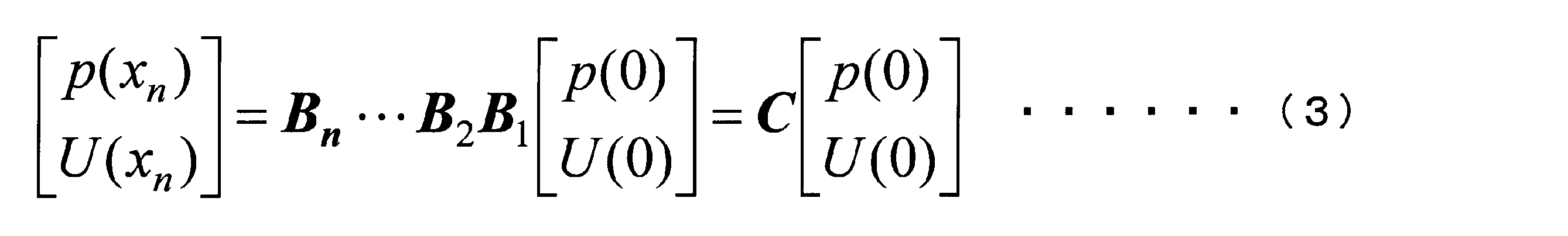
- the temperature gradient of each regenerator is obtained using the condition that “the enthalpy flow H is constant in the regenerator”. From the equation (3), the starting impedance can be expressed by the following equation.
- the impedance distribution in the loop is obtained by using the value of equation (4) as the initial value.
- the amount of heat Q input to the engine and the work flow W were obtained by the following equations.
- C p is the isobaric specific heat
- ⁇ is the complex conjugate
- thermoacoustic engine Since the thermoacoustic engine has a loop shape, the start point and the end point are the same. Naturally, when the thermoacoustic engine is driven by an actual machine, the pressure amplitudes at the start point and the end point are the same. For example, if the acoustic impedance value at the start point is set to ⁇ c in the numerical simulation, and the pressure amplitude value at the end point becomes equal to the pressure amplitude value at the start point, the thermoacoustic engine is actually driven in the actual machine. It will be.
- the diameter and length of the resonance tubes 10e and 10f By changing the diameter and length of the resonance tubes 10e and 10f so that the pressure amplitude value at the end point becomes the pressure amplitude value at the start point, the spatial change of the real part and the imaginary part of the pressure amplitude is adjusted, and numerical simulation is performed. Above, the boundary condition that “the pressure amplitude of the start point and the end point is the same” is satisfied. If the above-described boundary conditions are satisfied in the numerical simulation, the actual machine is similarly driven with the acoustic impedance value at the starting point at ⁇ c.
- the diameter is changed from the resonance tube 10e to 10f by one step to be the same as 10a. However, for example, it may be tapered to have the same diameter as the resonance tube 10a.
- FIGS. 5A and 5B The acoustic impedance distribution in the numerical calculation model of this embodiment is shown in FIGS. 5A and 5B, the phase difference between the pressure and the flow velocity is shown in FIG. 6, and the work flow W distribution is shown in FIG.
- the hatching in the figure is the position of each prime mover (denoted as Unit in the figure).
- 5A shows a real part
- FIG. 5B shows an imaginary part.
- FIG. 7 is normalized to a value based on the starting point by dividing the value W of the work flow W at an arbitrary point by the value W 0 of the work flow W at the starting point.
- the acoustic impedance is approximately 4973.4 Ns / m 3 in each of the resonance tubes 10a to 10e, and at the same time, in FIG. 5 (b), the imaginary part of the acoustic impedance of each resonance tube. Is almost zero. Further, the phase difference between the pressure and the flow velocity in FIG. 6 is within ⁇ 19 ° over the entire region of the resonance tubes 10a to 10e, and it can be confirmed that the traveling wave sound field is substantially realized in the proposed configuration.
- the work flow W amplification factor of each regenerator in this example is 1.91, 1.90, 1.91, 1.91 times, and it has succeeded in obtaining an amplification factor relatively close to the temperature ratio. is doing.
- the amplification factor of the final work flow W reached 12.4 times. In the resonance tube, since a traveling wave of about ⁇ c is realized, the attenuation of the work flow W due to viscous dissipation is very small.
- FIGS. 8 The heat flow components of the regenerator in each prime mover are shown in FIGS. 8, (a) is a heat accumulator (heat accumulator 1) in the motor 20a, (b) is a heat accumulator (heat accumulator 2) in the motor 20b, and (a) is a heat accumulator (heat accumulator) in the motor 20c. 3) and (b) are heat flow components of the heat accumulator (heat accumulator 4) in the prime mover 20d.
- W is the work flow
- Q prog is the heat flow due to the traveling wave
- Q stand is the heat flow due to the standing wave
- Q D is the heat flow due to the dream pipe effect
- the horizontal axis indicates the position inside each regenerator. ing.
- a traveling wave with high acoustic impedance is realized at each heat accumulator position, so that the heat flow due to the dream pipe effect and the heat flow due to the standing wave are extremely small.
- the thermal efficiency of each regenerator is 34.1% for regenerator 1, 33.6% for regenerator 2, 34.5% for regenerator 3, and 33.5% for regenerator 4. It was. Moreover, the thermal efficiency of the whole apparatus calculated
- the thermal efficiency is obtained by dividing the amplification amount ( ⁇ W) of the work flow W in the thermoacoustic engine by the sum of input heat amounts (Q D + Q prog + Q stand ).
- Q D and Q prog and Q stand is the value of the end portion of the heater side of the regenerator and the right end of the value in the graph.
- thermoacoustic engine for a multistage thermoacoustic engine, “a traveling wave with high acoustic impedance is realized at all the regenerator positions”, and at the same time, “a traveling wave having an acoustic impedance value of about ⁇ c at positions other than the regenerators”
- thermoacoustic generator and the thermoacoustic refrigerator are not limited to those described above, but in other commonly used thermoacoustic generators and thermoacoustic refrigerators
- the configuration of the present invention can also be applied.
- the configuration of the generator linear generator
- any configuration can be used as long as the generator is used as a thermoacoustic generator. May be.
- the shape of the resonance tube or the refrigeration loop tube as a whole in plan view is a rounded square in the above-described embodiment, but these shapes are not limited to this, for example, a square or a circle Alternatively, it may be oval.
- the number of prime movers has been described as four, the number is arbitrary, and up to about 2 to 20 can be installed in the path of the resonance tube.
- the resonance tube connected to the branch tube is composed of the resonance tube 10f and the resonance tube 10a. However, these may be a single resonance tube having the same diameter (inner diameter).
- the resonance tube 10e and the resonance tube 10f are separate resonance tubes here, they may be integrated into one resonance tube.
Landscapes
- Engineering & Computer Science (AREA)
- Mechanical Engineering (AREA)
- General Engineering & Computer Science (AREA)
- Chemical & Material Sciences (AREA)
- Combustion & Propulsion (AREA)
- Physics & Mathematics (AREA)
- Thermal Sciences (AREA)
- Exhaust Silencers (AREA)
- Heat-Exchange Devices With Radiators And Conduit Assemblies (AREA)
Abstract
Description
ここで、一般的に試みられている熱音響機関の動作温度は500℃程度であり(非特許文献3参照)、現実の自動車や工場からの廃熱温度(100℃~300℃程度)と比較して格段に高温である。そこで、熱音響機関の動作温度を低下させる試みとしては、近年、蓄熱器を多段直列配置することで、各蓄熱器で仕事流Wの累乗増幅を実現する「多段熱音響機関」が提案されている(非特許文献4参照)。
進行波型の熱音響エンジンは、等温可逆的な熱交換によってエネルギ変換を行うために、理想的にはカルノー効率が期待できる。しかしながら、これを実現するためには外部入力、又は音波のフィードバックが必須である。1998年に矢崎らはトーラス型のループ内に蓄熱器を設置することで音波のフィードバックを行い、初めて実用的な進行波型エンジンを実証した(T.Yazaki et.al., Phys. Rev. Lett. 81, pp.3128-3131, 1988.)。しかし、スタック位置が低音響インピーダンス(圧力と流速の比)であるために、粘性散逸とドリームパイプ効果が大きいという面が存在した。ドリームパイプ効果とは以下の事項をいう。温度勾配のある容器内の流体を外部ピストン等で強制振動させると、高温部から低温部へと非常に大きな熱流が発生する。その有効的熱輸送量は振動がない場合の1000倍以上に達する。結果的に流体を振動させただけで金属の熱伝導度を上回る熱輸送が可能となる。しかしながら、エンジンとして熱音響機関を用いる場合には、低温側への熱輸送は効率の低下につながるため、ドリームパイプ効果は熱音響エンジンの効率を低下させる大きな要因となる。
そして、加熱器に連結する共鳴管の流路断面積を、冷却器に連結する共鳴管の流路断面積に対し、自励振動による仕事流Wの増幅率と同じ、あるいはそれの±30%の範囲内にある増幅率で拡大することで、蓄熱器以外の位置では音響インピーダンスの値がρc程度の進行波とすることができる。また、蓄熱器の流路断面積を、冷却器に連結する共鳴管の流路断面積の4~36倍とすることで、蓄熱器位置全てで高音響インピーダンスの進行波とすることができる。
このような構成によれば、作動気体に発生した自励振動による音響エネルギが、発電機によって電気エネルギに変換される。そして、熱音響発電機として、低温かつ高効率で駆動することができる。
また、熱音響発電機として用いた場合、従来の熱音響機関と比較して発電量の向上が可能であり、熱音響冷凍機として用いた場合、従来の熱音響機関と比較して低温で高熱効率の駆動を実現することが可能である。
図1に示すように、熱音響機関1は、作動気体が封入され、全体として環状に形成された複数の共鳴管10a~10fと、前記複数の共鳴管10a~10fを連結する複数の原動機20(20a~20d)と、前記複数の共鳴管10a~10fのうち、環状を形成するループの始点と終点との交点から、共鳴管10に連通して一端が接続された枝管(枝管共鳴管)11とを有する。
以下、各構成について説明する。
共鳴管10a~10fは、作動気体が満たされる管であり、全体として環状に形成されている。ここでは、6本の共鳴管10a~10fからなり、原動機20を介して接続されて環を構成し、環状の共鳴管10を構成している。すなわち、共鳴管10bは、図1における紙面上、右側に配置されてその上下が湾曲し、共鳴管10dは、図1における紙面上、左側に配置されてその上下が湾曲している。また、共鳴管10a、10c、10e、10fは、直線状の管である。ここで、図1の破線(符号A1)を基準として図1における紙面上、右側の管部が共鳴管10aであり、左側の管部が共鳴管10fである。共鳴管10aと共鳴管10fの境界は厳密に規定されるものではなく、例えば、符号A1の破線が、紙面上、やや右側、あるいは左側に位置するものであってもよい。そして、これら共鳴管10a~10fにより、全体としての共鳴管10a~10fからなる管路は角丸の四角形に形成され、環状を構成している。
この始点および終点では、共鳴管10eおよび10fの流路断面積並びに長さを変更し、調整することで、共鳴管10aと圧力振幅を同等とする。
そして、この共鳴管10における始点および終点の位置(すなわち交点)に連通して枝管11が分岐状に接続されている。
枝管11は、作動気体が封入される直線状の管であり、その一端11aが共鳴管10の一部、ここでは、共鳴管10aと共鳴管10fの連結部に連通して、すなわち作動気体が共鳴管10と枝管11とを流通可能な状態で接続されている。つまり枝管11は、前記複数の共鳴管10a~10fのうち、環状を形成するループの始点と終点との位置(交点)から、共鳴管10に連通して分岐している。なお、「始点および終点の位置から分岐している」とは、枝管11と共鳴管10の連結部分における、枝管11の延長線上がこの始点および終点を含むことを意味する。ここで、図1の破線(符号A2)を基準として図1における紙面上、上側の管部が枝管11であり、下側の管部が共鳴管10(10f,10a)である。枝管11と共鳴管10の境界は厳密に規定されるものではなく、例えば、符号A2の破線が、紙面上、やや上側に位置するものであってもよい。
なお、作動気体としては、窒素、ヘリウム、アルゴン、ヘリウムとアルゴンとの混合物や空気等がよく用いられる。
原動機20は、複数の共鳴管10a~10fを連結している。「原動機が共鳴管を連結している」とは、封入した作動気体が流通可能なように、原動機を介して共鳴管が接続されている状態をいう。ここでは、4つの原動機20a~20dが共鳴管10a~10eに連結され、共鳴管10fが共鳴管10eおよび10aに連結することで、共鳴管10a~10fが一体の環状の共鳴管10として原動機20a~20dにより連結されている。
原動機20の構成について、ここでは、原動機20aを取り上げて説明するが、原動機20b~20dについても原理は同様である。
蓄熱器(原動機用蓄熱器)21は、共鳴管10の管路に設けられ、作動気体を加熱および冷却するものである。
蓄熱器21は、加熱器22および冷却器23によって蓄熱器21の両端部間に温度勾配を形成して作動気体の自励振動を発生させる。すなわち蓄熱器21は、その一端部(以下、適宜、高温部21bと称する)と、その他端部(以下、適宜、常温部(原動機側常温部)21aと称する)との間に生じる温度差を保つことによって、主として作動気体の自励振動(圧力振動)による仕事流Wを発生する機能を有している。蓄熱器21は、例えば共鳴管10の延在方向(管路方向)に多数の平行通路を有するセラミックス製のハニカム構造体や、多数枚のステンレス鋼メッシュ薄板を微小ピッチで積層した構造体とすることができる。あるいは金属繊維よりなる不織布状物等を用いることも可能である。
加熱器22は、蓄熱器21の一端側に隣接して共鳴管10の管路に設けられ、蓄熱器21の一端部(高温部21b)を加熱するものである。すなわち加熱器22は、外部熱源に接続して蓄熱器21の一端を加熱する熱入力部として機能する。加熱器22は、例えば、加熱用の熱交換器から構成される。具体的には、例えば、メッシュ板等の多数枚の金属板が微小ピッチで積層された構成とされる。この加熱器22には図示しない加熱装置が接続されており、その外周に設けられた環状部材22aを介して加熱処理される構成になっている。なお、図面では便宜上、蓄熱器21と加熱器22の間に環状部材22aの左壁が示されているが、加熱器22は、この左壁を通して蓄熱器21の一端側と隣接、すなわち密着している。
冷却器23は、蓄熱器21の他端側に隣接して共鳴管10の管路に設けられ、蓄熱器21の他端部(常温部21a)の熱を外部に放出するものである。すなわち冷却器23は、冷却水や空気等を用いて蓄熱器21の他端の熱を外部に放出して冷却する機能を有している。冷却器23は、例えば、冷却用の熱交換器から構成される。冷却器23としては、基本的には加熱器22と同一構成で、例えば、メッシュ板等の多数枚の金属板が微小ピッチで積層された構成になっている。この冷却器23は、その周囲に冷却ブラケット23aが配設されている。この冷却ブラケット23aには図示しない冷却水路が接続されており、冷却水路を流れる冷却水により、冷却器23は冷却ブラケット23aを介して一定の冷却温度を維持しうる構成になっている。なお、図面では便宜上、蓄熱器21と冷却器23の間に冷却ブラケット23aの右壁が示されているが、冷却器23は、この右壁を通して蓄熱器21の他端側と隣接、すなわち密着している。
ここで、ρは作動気体の密度,cは音速であり、ρcは物理値として一定になる。例えば0.1MPaの空気(300K)の場合ρcは約403.3Ns/m3,3.0MPaの空気(300K)の場合ρcは約12098.1Ns/m3,0.1MPaのヘリウム(300K)の場合ρcは約163.6Ns/m3,0.1MPaのアルゴン(300K)の場合ρcは約517.0Ns/m3である。「ρc程度」とは、音響インピーダンスの値がρcと同一の場合の他、例えば、±30%程度の範囲内であってもよいことを意味する。すなわち、前記のρcの値に対する±30%の範囲内であり、±15%であることがより好ましい。
気体の圧力振幅を、P=|P|exp(iωt)
音波の流速振幅を、U=|U|exp{i(ωt+φ)}
とするとき、
Ζ=P/U={|P|exp(iωt)}/{|U|exp{i(ωt+φ)}}
例えば、原動機20aでは、この原動機20aの加熱器22に連結する共鳴管10bの流路断面積は、この蓄熱器21を備える原動機20aの冷却器23に連結する共鳴管10aの流路断面積に対し、自励振動による仕事流Wの増幅率と同じ、あるいはそれの±30%の範囲内にある増幅率で拡大している。原動機20b~20dに連結する共鳴管10b~10eについても同様である。
ここで、「共鳴管の流路断面積」とは、長手方向(流路方向)に対して垂直に切断した場合の流路の断面積であり、管の内径の面積、すなわち、仕事流Wが流通する部位の面積である。「仕事流W」とは、作動気体の振動に基づく仕事、エネルギの移動を意味し、音波によって運ばれる力学的エネルギであり、後記する実施例での式(6)で定義される。具体的には、圧力振幅と断面平均体積流速振幅を乗じ、2で除したものが仕事流Wの値になる。
共鳴管10bの流路断面積を、仕事流Wの増幅率と同じ、あるいはそれの±30%の範囲内にある増幅率で共鳴管10aの流路断面積に対して拡大することで、共鳴管10bにおいても、音響インピーダンスの値がρc程度の進行波を実現することができる。共鳴管10c~10eについても同様である。
すなわち仕事流Wは、ZR(音響インピーダンス実数部)と次式で関係づけられる。
W=(A/2)(ZR)|U|2
このときZR:音響インピーダンス実数部,A:管内流路断面積,U:流速振幅である。
上式で与えられる仕事流Wの符号は音響パワーの流れの向きを表す。正ならば座標軸の向きに流れ、負ならば逆方向への流れを表す。
例えば、原動機20aの蓄熱器21の流路断面積は、原動機20aに連結する共鳴管10aの流路断面積の4~36倍とする。原動機20b~20dについても同様である。
ここで、「蓄熱器の流路断面積」とは、共鳴管の流路断面積に対向する面の断面積であり、仕事流Wが流通する部位の面積である。
蓄熱器の流路断面積を、冷却器に連結する共鳴管の流路断面積の4~36倍とすることで、蓄熱器位置全てで高音響インピーダンスの進行波とすることができる。なお、4倍未満、あるいは36倍を超えても、蓄熱器の流路断面積が、冷却器に連結する共鳴管の流路断面積よりも大きければ、音響インピーダンスはある程度高くはなるが、4~36倍の範囲内に比べると高くはなく、熱効率が低下し、実用的ではない。また、36倍を超えると、熱音響機関のサイズが大きくなり、生産性に劣るという問題や、取り扱いが不便になるという問題が生じる。よって、本発明においては、熱効率が比較的高く、かつ生産性や取り扱い等を考慮して、4~36倍の範囲に規定することとした。
次に、図面を参照して、熱音響機関を用いた熱音響機関の一例として、前記の熱音響機関1を用いた場合の熱音響発電機および熱音響冷凍機について説明する。
図2に示すように、熱音響発電機50は、前記した熱音響機関1に加え、さらに、枝管11の他端11bに接続され、枝管11に連通して、作動気体に発生する自励振動に応動して発電を行なう発電機(リニア発電機)30を備えるものである。発電機30を備える以外については、前記の熱音響機関1で説明したとおりであるので、ここでは発電機30について説明する。
発電機30は、枝管11の他端11bに接続され、枝管11に連通して、さらに共鳴管10の一部(共鳴管10f,10a)に連通するかたちで設けられており、作動気体に発生する自励振動に応動して発電を行なうリニア発電機として機能する。すなわち、音響エネルギEである自励振動に基づき内側ヨーク33を往復振動させて、音響エネルギEを電気エネルギに変換するものである。これにより、枝管11を通って伝達した音響エネルギEを、内側ヨーク33の往復運動を介して電気エネルギに変換する、いわゆる熱音響発電機50を形成することができる。ここで、図2の破線(符号A3)を基準として図2における紙面上、上側が発電機30であり、下側の管部が枝管11である。枝管11と発電機30の境界は厳密に規定されるものではなく、符号A3の破線が、紙面上、やや下側に位置するものであってもよい。
図3に示すように、熱音響冷凍機60は、前記した熱音響機関1に加え、さらに、枝管11の他端11bに連通して接続された環状の冷凍用ループ管12を有する。そして、冷凍用ループ管12の管路に、冷凍機40として、冷凍用蓄熱器41と、冷凍用冷却器43と、冷気放出器42と、を備える。冷凍機40および冷凍用ループ管12を備える以外については、前記の熱音響機関1で説明したとおりであるので、ここでは冷凍機40およびこれを管路に備える冷凍用ループ管12について説明する。
冷凍用ループ管12は、作動気体が封入される環状の管であり、その管路は角丸の四角形に形成され、四辺に該当する直線部を形成する直管部12a~12dからなる。すなわち、四辺に該当する直線部を形成する縦方向に略平行に並んだ2つの直管部12a、12bと、横方向に略平行に並んだ2つの直管部12c、12dと、を有している。そして、直管部12aの一端と直管部12cの一端、直管部12bの一端と直管部12cの他端、直管部12bの他端と直管部12dの一端が接続されて湾曲している。また、直管部12aの他端と直管部12dの他端が接続されるとともに、この部位において、冷凍用ループ管12に連通して枝管11の他端11bが接続されている。ここで、図3の破線(符号A4)を基準として図3における紙面上、上側の管部が冷凍用ループ管12であり、下側の管部が枝管11である。ここでは、枝管11における冷凍用ループ管12との接続部は、右側が湾曲しているが、直角に形成しているものであってもよい。また、枝管11と冷凍用ループ管12の境界は厳密に規定されるものではなく、符号A4の破線が、紙面上、やや下側(例えば、前記湾曲していない部分)に位置するものであってもよい。
冷凍機40は、原動機20によって発生する作動気体の自励振動による仕事流Wを冷気(冷熱)に変換するヒートポンプ手段として機能するものである。冷凍機40は、冷凍用ループ管12内に設けられた冷凍用蓄熱器41と、冷凍用蓄熱器41の両端を挟むように設けられた冷凍用冷却器43および冷気放出器42とを有している。より具体的には、冷凍機40は、本実施形態において、冷凍用ループ管12における枝管11が接続されている側、すなわち冷凍用ループ管12の直管部12aの管路に設けられている。そして、冷凍用冷却器43は冷凍用蓄熱器41の直管部12c側に配置され、冷気放出器42はその反対側、すなわち冷凍用蓄熱器41の直管部12d側に配置されている。
冷凍用蓄熱器41は、冷凍用ループ管12の管路に設けられ、作動気体を冷却するものである。
冷凍用蓄熱器41は、原動機20から、枝管11、冷凍用ループ管12の直管部12d,12b,12c,12aの順にこれらの管を通じて冷凍用蓄熱器41の一端部(以下、適宜、常温部(冷凍機側常温部)41aと称する)に伝達された自励振動を、冷凍用蓄熱器41の一端部(常温部41a)と冷凍用蓄熱器41の他端部(以下、適宜、低温部41bと称する)との間における温度差に変換する機能を有している。冷凍用蓄熱器41の常温部41aは冷凍用冷却器43によって冷却されているため、伝達された自励振動によって、冷凍用蓄熱器41の低温部41bは、常温部41aよりも低い温度まで冷却されて冷気が発生する。この冷気は、冷気放出器42によって外部に取り出される。冷凍用蓄熱器41は、熱容量の大きい蓄冷材からなる。蓄冷材としては、例えば、ステンレス鋼、銅、鉛等を用いることができ、またその形状は多様な形状を適用することが可能である。
冷凍用冷却器43は、冷凍用蓄熱器41の自励振動が伝わる一端側に隣接して冷凍用ループ管12の管路に設けられ、冷凍用蓄熱器41の一端部(常温部41a)の熱を外部に放出するものである。すなわち冷凍用冷却器43は、冷却水や空気等を用いて冷凍用蓄熱器41の一端の熱を外部に放出して冷却する機能を有している。冷凍用冷却器43は、例えば、冷却用の熱交換器から構成される。具体的には、例えば、メッシュ板等の多数枚の金属板が微小ピッチで積層された構成になっている。この冷凍用冷却器43は、その周囲に冷却ブラケット43aが配設されている。この冷却ブラケット43aには図示しない冷却水路が接続されており、冷却水路を流れる冷却水により、冷凍用冷却器43は冷却ブラケット43aを介して一定の冷却温度を維持しうる構成になっている。なお、図面では便宜上、冷凍用蓄熱器41と冷凍用冷却器43の間に冷却ブラケット43aの左壁が示されているが、冷凍用冷却器43は、この左壁を通して冷凍用蓄熱器41の一端側と隣接、すなわち密着している。
冷気放出器42は、冷凍用蓄熱器41の他端側に隣接して冷凍用ループ管12の管路に設けられ、冷凍用蓄熱器41の他端部(低温部41b)に発生する冷気を外部に放出するものである。すなわち冷気放出器42は、冷凍用蓄熱器41の他端において発生する冷気を外部に取り出す冷気出力部として機能する。冷気放出器42は、例えば、冷凍用の熱交換器から構成される。冷気放出器42としては、基本的には冷凍用冷却器43と同一構成とされており、例えば、メッシュ板等の多数枚の金属板が微小ピッチで積層された構成とされている。この冷気放出器42の外周位置には、冷気(冷熱)を取り出す高熱伝導率材料(例えば、銅)よりなる環状部材42aが配設されている。なお、図面では便宜上、冷凍用蓄熱器41と冷気放出器42の間に環状部材42aの右壁が示されているが、冷気放出器42は、この右壁を通して冷凍用蓄熱器41の他端側と隣接、すなわち密着している。
次に熱音響機関の動作について、前記説明した熱音響発電機および熱音響冷凍機を例にして図2および図3を参照して説明する。
図2に示すように、まず、原動機20において、加熱器22によって蓄熱器21の高温部21bを加熱し、かつ、冷却器23によって蓄熱器21の常温部21aを冷却すると、蓄熱器21の両端に、すなわち、高温部21bと常温部21aとの間に温度差が生じる。この温度差により、原動機20(具体的には、蓄熱器21)には、主として作動気体の自励振動による仕事流Wが生じる。そして、原動機20において発生した自励振動による仕事流Wは、音響エネルギEとして、例えば原動機20aでは、共鳴管10b,10c,10d、10e、10f、枝管11の順にこれらの管を通じて発電機30へと伝達される。原動機20b~20dおいても同様に、発生した自励振動による仕事流Wは、音響エネルギEとして、共鳴管10、枝管11を通じて発電機30へと伝達される。そして発電機30に伝達された自励振動に基づき内側ヨーク33を往復振動させることで、音響エネルギEが電気エネルギに変換されて発電が行なわれる。
図3に示すように、前記した熱音響発電機の動作と同様にして、原動機20(具体的には、蓄熱器21)に主として作動気体の自励振動による仕事流Wが生じる。そして、原動機20において発生した自励振動による仕事流Wは、音響エネルギEとして枝管11を通じて冷凍機40へと伝達される。より具体的には、例えば原動機20aでは、蓄熱器21の高温部21bから、音響エネルギEとして共鳴管10b,10c,10d、10e、10f、枝管11、冷凍用ループ管12の直管部12d,12b,12c,12aを通じて冷凍用蓄熱器41の常温部41aへと伝達される。原動機20b~20dおいても同様に、発生した自励振動による仕事流Wは、音響エネルギEとして、共鳴管10、枝管11、冷凍用ループ管12を通じて冷凍機40へと伝達される。
ここでは、冷却器、加熱器および蓄熱器からなる原動機(ゼロ点(0の点)から時計回りに原動機20a,20b,20c,20dとする)を、共鳴管10a~10f、枝管11で構成した枝付きループ管内に四ヶ所設置する多段増幅型熱音響エンジンを計算モデルの一例として用いた。なお、図中、L1~L6は、それぞれ共鳴管10a~10fの長さである。


「熱効率η=△W/(QD+Qprog+Qstand)」
また、ここでは、枝管に接続される共鳴管は、共鳴管10fと共鳴管10aとからなるが、これらは直径(内径)が同一の一体とした1つの共鳴管としてもよい。同様に、共鳴管10eと共鳴管10fは、ここでは別の共鳴管としたが、これらを一体とした1つの共鳴管としてもよい。
10,10a~10f 共鳴管
11 枝管
12 冷凍用ループ管
20,20a~20d 原動機
21 蓄熱器
22 加熱器
23 冷却器
30 発電機(リニア発電機)
40 冷凍機
41 冷凍用蓄熱器
42 冷気放出器
43 冷凍用冷却器
50 熱音響発電機
60 熱音響冷凍機
Claims (3)
- 作動気体が封入され、全体として環状に形成された複数の共鳴管と、前記複数の共鳴管を連結する複数の原動機と、前記複数の共鳴管のうち、環状を形成するループの始点と終点との交点から、前記共鳴管に連通して一端が接続された枝管とを有し、
前記原動機は、前記作動気体を加熱および冷却する蓄熱器と、前記蓄熱器の一端側に隣接して前記蓄熱器の一端部を加熱する加熱器と、前記蓄熱器の他端側に隣接して前記蓄熱器の他端部の熱を外部に放出する冷却器とを備え、前記蓄熱器の両端部間に温度勾配を形成させて前記作動気体の自励振動を発生させる熱音響機関であって、
前記各加熱器に連結する共鳴管の流路断面積は、当該加熱器を備える原動機の冷却器に連結する共鳴管の流路断面積に対し、前記自励振動による仕事流の増幅率と同じ、あるいはそれの±30%の範囲内にある増幅率で拡大したものであり、
前記蓄熱器の流路断面積は、当該蓄熱器を備える原動機の冷却器に連結する共鳴管の流路断面積の4~36倍であることを特徴とする熱音響機関。 - さらに、前記枝管の他端に接続され、前記枝管に連通して、前記作動気体に発生する自励振動に応動して発電を行なう発電機を備えることを特徴とする請求項1に記載の熱音響機関。
- さらに、前記枝管の他端に連通して接続された環状の冷凍用ループ管を有し、前記冷凍用ループ管の管路に設けられ、前記作動気体を冷却する冷凍用蓄熱器と、前記冷凍用蓄熱器の前記自励振動が伝わる一端側に隣接して前記冷凍用ループ管の管路に設けられ、前記冷凍用蓄熱器の一端部の熱を外部に放出する冷凍用冷却器と、前記冷凍用蓄熱器の他端側に隣接して前記冷凍用ループ管の管路に設けられ、前記冷凍用蓄熱器の他端部に発生する冷気を外部に放出する冷気放出器と、備えることを特徴とする請求項1に記載の熱音響機関。
Priority Applications (2)
| Application Number | Priority Date | Filing Date | Title |
|---|---|---|---|
| US14/362,973 US9777951B2 (en) | 2011-12-05 | 2012-11-30 | Thermoacoustic engine |
| JP2013548217A JP5970737B2 (ja) | 2011-12-05 | 2012-11-30 | 熱音響機関 |
Applications Claiming Priority (2)
| Application Number | Priority Date | Filing Date | Title |
|---|---|---|---|
| JP2011-266181 | 2011-12-05 | ||
| JP2011266181 | 2011-12-05 |
Publications (1)
| Publication Number | Publication Date |
|---|---|
| WO2013084830A1 true WO2013084830A1 (ja) | 2013-06-13 |
Family
ID=48574197
Family Applications (1)
| Application Number | Title | Priority Date | Filing Date |
|---|---|---|---|
| PCT/JP2012/081193 Ceased WO2013084830A1 (ja) | 2011-12-05 | 2012-11-30 | 熱音響機関 |
Country Status (3)
| Country | Link |
|---|---|
| US (1) | US9777951B2 (ja) |
| JP (1) | JP5970737B2 (ja) |
| WO (1) | WO2013084830A1 (ja) |
Cited By (14)
| Publication number | Priority date | Publication date | Assignee | Title |
|---|---|---|---|---|
| CN103670788A (zh) * | 2013-12-11 | 2014-03-26 | 中国科学院理化技术研究所 | 同时利用冷热源的声学共振型多级行波热声发动机系统 |
| JP2015055438A (ja) * | 2013-09-13 | 2015-03-23 | 学校法人東海大学 | 熱音響機関及びその製造方法 |
| JP2015145752A (ja) * | 2014-02-03 | 2015-08-13 | 東邦瓦斯株式会社 | 熱音響装置用の蓄熱器 |
| JP2016183767A (ja) * | 2015-03-26 | 2016-10-20 | 大阪瓦斯株式会社 | 気化設備 |
| JP2017184457A (ja) * | 2016-03-30 | 2017-10-05 | 学校法人東海大学 | 熱音響発電システム |
| JP2017211177A (ja) * | 2017-08-04 | 2017-11-30 | 学校法人東海大学 | 熱音響機関 |
| WO2017212871A1 (ja) * | 2016-06-09 | 2017-12-14 | 中央精機株式会社 | 熱音響エンジン、及び、熱音響エンジンの設計方法 |
| CN107532829A (zh) * | 2014-10-02 | 2018-01-02 | 西登斯安纳泰克私人有限公司 | 热声制冷机 |
| JP2018091531A (ja) * | 2016-12-01 | 2018-06-14 | 学校法人東海大学 | 熱音響機関 |
| CN108180673A (zh) * | 2017-12-21 | 2018-06-19 | 中国科学院理化技术研究所 | 一种环路热驱动热声制冷系统 |
| US10113440B2 (en) | 2015-05-21 | 2018-10-30 | Central Motor Wheel Co., Ltd. | Thermoacoustic electric generator system |
| US10495355B2 (en) | 2015-05-21 | 2019-12-03 | Central Motor Wheel Co., Ltd. | Thermoacoustic electric generator system |
| TWI738866B (zh) * | 2016-09-15 | 2021-09-11 | 日商捷太格特股份有限公司 | 輸送裝置 |
| CN114687882A (zh) * | 2020-12-29 | 2022-07-01 | 中国科学院理化技术研究所 | 一种高效环路型气液耦合热声系统 |
Families Citing this family (9)
| Publication number | Priority date | Publication date | Assignee | Title |
|---|---|---|---|---|
| US9163581B2 (en) * | 2012-02-23 | 2015-10-20 | The United States Of America As Represented By The Administrator Of National Aeronautics And Space Administration | Alpha-stream convertor |
| CN106194358B (zh) * | 2016-08-10 | 2019-06-28 | 中国科学院理化技术研究所 | 多级热声发电机组及具有该机组的多级回热式制冷系统 |
| CN108933979B (zh) * | 2017-05-25 | 2020-10-30 | 中国科学院理化技术研究所 | 一种多级声功放大的开口式热声发生器 |
| JP6829319B2 (ja) * | 2017-09-06 | 2021-02-10 | 中央精機株式会社 | 熱音響温調システム |
| JP6755442B1 (ja) * | 2019-06-12 | 2020-09-16 | 学校法人東海大学 | 蓄熱器の設計方法、設計装置及びプログラム |
| CN113137778B (zh) * | 2020-01-18 | 2023-02-10 | 中国科学院理化技术研究所 | 无运动部件的冷热电联供系统 |
| CN113310247A (zh) * | 2020-06-02 | 2021-08-27 | 中国科学院理化技术研究所 | 室温温区多级热声制冷机 |
| CN116263277B (zh) * | 2021-12-13 | 2026-01-20 | 中国科学院理化技术研究所 | 环路多级热驱动热泵 |
| CN120351618B (zh) * | 2025-06-10 | 2025-11-18 | 中科联合数字技术(苏州)有限公司 | 一种中央空调冷热源机房能效管理系统 |
Citations (4)
| Publication number | Priority date | Publication date | Assignee | Title |
|---|---|---|---|---|
| US5901556A (en) * | 1997-11-26 | 1999-05-11 | The United States Of America As Represented By The Secretary Of The Navy | High-efficiency heat-driven acoustic cooling engine with no moving parts |
| JP2006118728A (ja) * | 2004-10-19 | 2006-05-11 | Daikin Ind Ltd | 熱音響冷凍機 |
| JP2006214406A (ja) * | 2005-02-07 | 2006-08-17 | Denso Corp | 熱音響装置 |
| JP2010261687A (ja) * | 2009-05-11 | 2010-11-18 | Isuzu Motors Ltd | 熱音響機関 |
Family Cites Families (3)
| Publication number | Priority date | Publication date | Assignee | Title |
|---|---|---|---|---|
| US6032464A (en) * | 1999-01-20 | 2000-03-07 | Regents Of The University Of California | Traveling-wave device with mass flux suppression |
| JP4364032B2 (ja) * | 2004-03-26 | 2009-11-11 | 学校法人同志社 | 熱音響装置 |
| JP5098534B2 (ja) | 2007-09-20 | 2012-12-12 | アイシン精機株式会社 | 熱音響機関 |
-
2012
- 2012-11-30 US US14/362,973 patent/US9777951B2/en active Active
- 2012-11-30 WO PCT/JP2012/081193 patent/WO2013084830A1/ja not_active Ceased
- 2012-11-30 JP JP2013548217A patent/JP5970737B2/ja active Active
Patent Citations (4)
| Publication number | Priority date | Publication date | Assignee | Title |
|---|---|---|---|---|
| US5901556A (en) * | 1997-11-26 | 1999-05-11 | The United States Of America As Represented By The Secretary Of The Navy | High-efficiency heat-driven acoustic cooling engine with no moving parts |
| JP2006118728A (ja) * | 2004-10-19 | 2006-05-11 | Daikin Ind Ltd | 熱音響冷凍機 |
| JP2006214406A (ja) * | 2005-02-07 | 2006-08-17 | Denso Corp | 熱音響装置 |
| JP2010261687A (ja) * | 2009-05-11 | 2010-11-18 | Isuzu Motors Ltd | 熱音響機関 |
Cited By (16)
| Publication number | Priority date | Publication date | Assignee | Title |
|---|---|---|---|---|
| JP2015055438A (ja) * | 2013-09-13 | 2015-03-23 | 学校法人東海大学 | 熱音響機関及びその製造方法 |
| CN103670788B (zh) * | 2013-12-11 | 2015-07-08 | 中国科学院理化技术研究所 | 同时利用冷热源的声学共振型多级行波热声发动机系统 |
| CN103670788A (zh) * | 2013-12-11 | 2014-03-26 | 中国科学院理化技术研究所 | 同时利用冷热源的声学共振型多级行波热声发动机系统 |
| JP2015145752A (ja) * | 2014-02-03 | 2015-08-13 | 東邦瓦斯株式会社 | 熱音響装置用の蓄熱器 |
| CN107532829A (zh) * | 2014-10-02 | 2018-01-02 | 西登斯安纳泰克私人有限公司 | 热声制冷机 |
| JP2016183767A (ja) * | 2015-03-26 | 2016-10-20 | 大阪瓦斯株式会社 | 気化設備 |
| US10113440B2 (en) | 2015-05-21 | 2018-10-30 | Central Motor Wheel Co., Ltd. | Thermoacoustic electric generator system |
| US10495355B2 (en) | 2015-05-21 | 2019-12-03 | Central Motor Wheel Co., Ltd. | Thermoacoustic electric generator system |
| JP2017184457A (ja) * | 2016-03-30 | 2017-10-05 | 学校法人東海大学 | 熱音響発電システム |
| WO2017212871A1 (ja) * | 2016-06-09 | 2017-12-14 | 中央精機株式会社 | 熱音響エンジン、及び、熱音響エンジンの設計方法 |
| US10844847B2 (en) | 2016-06-09 | 2020-11-24 | Central Motor Wheel Co., Ltd. | Thermoacoustic engine |
| TWI738866B (zh) * | 2016-09-15 | 2021-09-11 | 日商捷太格特股份有限公司 | 輸送裝置 |
| JP2018091531A (ja) * | 2016-12-01 | 2018-06-14 | 学校法人東海大学 | 熱音響機関 |
| JP2017211177A (ja) * | 2017-08-04 | 2017-11-30 | 学校法人東海大学 | 熱音響機関 |
| CN108180673A (zh) * | 2017-12-21 | 2018-06-19 | 中国科学院理化技术研究所 | 一种环路热驱动热声制冷系统 |
| CN114687882A (zh) * | 2020-12-29 | 2022-07-01 | 中国科学院理化技术研究所 | 一种高效环路型气液耦合热声系统 |
Also Published As
| Publication number | Publication date |
|---|---|
| US20140338369A1 (en) | 2014-11-20 |
| JP5970737B2 (ja) | 2016-08-17 |
| JPWO2013084830A1 (ja) | 2015-04-27 |
| US9777951B2 (en) | 2017-10-03 |
Similar Documents
| Publication | Publication Date | Title |
|---|---|---|
| JP5970737B2 (ja) | 熱音響機関 | |
| JP5892582B2 (ja) | 熱音響機関 | |
| Bi et al. | Development of a 5 kW traveling-wave thermoacoustic electric generator | |
| Wang et al. | Thermoacoustic Stirling power generation from LNG cold energy and low-temperature waste heat | |
| US8584471B2 (en) | Thermoacoustic apparatus with series-connected stages | |
| JP2012112621A (ja) | 熱音響機関 | |
| JP6233835B2 (ja) | 熱音響機関及びその製造方法 | |
| US6560970B1 (en) | Oscillating side-branch enhancements of thermoacoustic heat exchangers | |
| Wang et al. | Numerical analysis on a four-stage looped thermoacoustic Stirling power generator for low temperature waste heat | |
| CN103758657B (zh) | 一种声学共振型行波热声发电系统 | |
| CN103835903B (zh) | 一种行波热声冷热电联供系统 | |
| CN100371657C (zh) | 脉冲管制冷机 | |
| WO2004015336A1 (en) | Circulating heat exchangers for oscillating wave engines and refrigerators | |
| JP7609497B2 (ja) | 熱音響システム及び熱音響システムの制御方法 | |
| Wang et al. | Theoretical analysis of a direct-coupled Stirling combined cooling and power system for heat recovery | |
| CN109974324B (zh) | 一种可用作发电、制冷或热泵的热声环路系统 | |
| Xiao et al. | Sustainable heat-driven sound cooler with super-high efficiency | |
| CN101566405B (zh) | 一种行驻波型声场的热驱动热声制冷机装置 | |
| Sun et al. | Numerical study on a three-stage traveling-wave thermoacoustic generator with a simplified structure simultaneously utilizing cold and low-grade thermal energy | |
| CN100432572C (zh) | 带有频率调制机械共振器的深冷冷却器系统及其操作方法 | |
| JP5453950B2 (ja) | 熱音響機関 | |
| Nakano et al. | Development of parallel thermoacoustic engine: Evaluations of onset temperature ratio and thermal efficiency | |
| Zhang et al. | Thermoacoustically driven single-stage pulse tube refrigerator below 50 K | |
| Wakeland et al. | Thermoacoustics with idealized heat exchangers and no stack | |
| JP6453393B2 (ja) | 熱音響機関の製造方法 |
Legal Events
| Date | Code | Title | Description |
|---|---|---|---|
| 121 | Ep: the epo has been informed by wipo that ep was designated in this application |
Ref document number: 12856215 Country of ref document: EP Kind code of ref document: A1 |
|
| ENP | Entry into the national phase |
Ref document number: 2013548217 Country of ref document: JP Kind code of ref document: A |
|
| NENP | Non-entry into the national phase |
Ref country code: DE |
|
| WWE | Wipo information: entry into national phase |
Ref document number: 14362973 Country of ref document: US |
|
| 122 | Ep: pct application non-entry in european phase |
Ref document number: 12856215 Country of ref document: EP Kind code of ref document: A1 |