WO2013080754A1 - 二重管式熱交換器及びこれを備えた空気調和装置 - Google Patents
二重管式熱交換器及びこれを備えた空気調和装置 Download PDFInfo
- Publication number
- WO2013080754A1 WO2013080754A1 PCT/JP2012/078678 JP2012078678W WO2013080754A1 WO 2013080754 A1 WO2013080754 A1 WO 2013080754A1 JP 2012078678 W JP2012078678 W JP 2012078678W WO 2013080754 A1 WO2013080754 A1 WO 2013080754A1
- Authority
- WO
- WIPO (PCT)
- Prior art keywords
- pipe
- heat exchanger
- refrigerant
- double
- liquid
- Prior art date
- Legal status (The legal status is an assumption and is not a legal conclusion. Google has not performed a legal analysis and makes no representation as to the accuracy of the status listed.)
- Ceased
Links
Images


Classifications
-
- F—MECHANICAL ENGINEERING; LIGHTING; HEATING; WEAPONS; BLASTING
- F25—REFRIGERATION OR COOLING; COMBINED HEATING AND REFRIGERATION SYSTEMS; HEAT PUMP SYSTEMS; MANUFACTURE OR STORAGE OF ICE; LIQUEFACTION SOLIDIFICATION OF GASES
- F25B—REFRIGERATION MACHINES, PLANTS OR SYSTEMS; COMBINED HEATING AND REFRIGERATION SYSTEMS; HEAT PUMP SYSTEMS
- F25B40/00—Subcoolers, desuperheaters or superheaters
- F25B40/02—Subcoolers
-
- F—MECHANICAL ENGINEERING; LIGHTING; HEATING; WEAPONS; BLASTING
- F25—REFRIGERATION OR COOLING; COMBINED HEATING AND REFRIGERATION SYSTEMS; HEAT PUMP SYSTEMS; MANUFACTURE OR STORAGE OF ICE; LIQUEFACTION SOLIDIFICATION OF GASES
- F25B—REFRIGERATION MACHINES, PLANTS OR SYSTEMS; COMBINED HEATING AND REFRIGERATION SYSTEMS; HEAT PUMP SYSTEMS
- F25B1/00—Compression machines, plants or systems with non-reversible cycle
- F25B1/005—Compression machines, plants or systems with non-reversible cycle of the single unit type
-
- F—MECHANICAL ENGINEERING; LIGHTING; HEATING; WEAPONS; BLASTING
- F25—REFRIGERATION OR COOLING; COMBINED HEATING AND REFRIGERATION SYSTEMS; HEAT PUMP SYSTEMS; MANUFACTURE OR STORAGE OF ICE; LIQUEFACTION SOLIDIFICATION OF GASES
- F25B—REFRIGERATION MACHINES, PLANTS OR SYSTEMS; COMBINED HEATING AND REFRIGERATION SYSTEMS; HEAT PUMP SYSTEMS
- F25B40/00—Subcoolers, desuperheaters or superheaters
-
- F—MECHANICAL ENGINEERING; LIGHTING; HEATING; WEAPONS; BLASTING
- F28—HEAT EXCHANGE IN GENERAL
- F28D—HEAT-EXCHANGE APPARATUS, NOT PROVIDED FOR IN ANOTHER SUBCLASS, IN WHICH THE HEAT-EXCHANGE MEDIA DO NOT COME INTO DIRECT CONTACT
- F28D7/00—Heat-exchange apparatus having stationary tubular conduit assemblies for both heat-exchange media, the media being in contact with different sides of a conduit wall
- F28D7/10—Heat-exchange apparatus having stationary tubular conduit assemblies for both heat-exchange media, the media being in contact with different sides of a conduit wall the conduits being arranged one within the other, e.g. concentrically
- F28D7/106—Heat-exchange apparatus having stationary tubular conduit assemblies for both heat-exchange media, the media being in contact with different sides of a conduit wall the conduits being arranged one within the other, e.g. concentrically consisting of two coaxial conduits or modules of two coaxial conduits
-
- F—MECHANICAL ENGINEERING; LIGHTING; HEATING; WEAPONS; BLASTING
- F28—HEAT EXCHANGE IN GENERAL
- F28D—HEAT-EXCHANGE APPARATUS, NOT PROVIDED FOR IN ANOTHER SUBCLASS, IN WHICH THE HEAT-EXCHANGE MEDIA DO NOT COME INTO DIRECT CONTACT
- F28D7/00—Heat-exchange apparatus having stationary tubular conduit assemblies for both heat-exchange media, the media being in contact with different sides of a conduit wall
- F28D7/10—Heat-exchange apparatus having stationary tubular conduit assemblies for both heat-exchange media, the media being in contact with different sides of a conduit wall the conduits being arranged one within the other, e.g. concentrically
- F28D7/14—Heat-exchange apparatus having stationary tubular conduit assemblies for both heat-exchange media, the media being in contact with different sides of a conduit wall the conduits being arranged one within the other, e.g. concentrically both tubes being bent
-
- F—MECHANICAL ENGINEERING; LIGHTING; HEATING; WEAPONS; BLASTING
- F25—REFRIGERATION OR COOLING; COMBINED HEATING AND REFRIGERATION SYSTEMS; HEAT PUMP SYSTEMS; MANUFACTURE OR STORAGE OF ICE; LIQUEFACTION SOLIDIFICATION OF GASES
- F25B—REFRIGERATION MACHINES, PLANTS OR SYSTEMS; COMBINED HEATING AND REFRIGERATION SYSTEMS; HEAT PUMP SYSTEMS
- F25B13/00—Compression machines, plants or systems, with reversible cycle
-
- F—MECHANICAL ENGINEERING; LIGHTING; HEATING; WEAPONS; BLASTING
- F25—REFRIGERATION OR COOLING; COMBINED HEATING AND REFRIGERATION SYSTEMS; HEAT PUMP SYSTEMS; MANUFACTURE OR STORAGE OF ICE; LIQUEFACTION SOLIDIFICATION OF GASES
- F25B—REFRIGERATION MACHINES, PLANTS OR SYSTEMS; COMBINED HEATING AND REFRIGERATION SYSTEMS; HEAT PUMP SYSTEMS
- F25B2313/00—Compression machines, plants or systems with reversible cycle not otherwise provided for
- F25B2313/027—Compression machines, plants or systems with reversible cycle not otherwise provided for characterised by the reversing means
- F25B2313/02741—Compression machines, plants or systems with reversible cycle not otherwise provided for characterised by the reversing means using one four-way valve
-
- F—MECHANICAL ENGINEERING; LIGHTING; HEATING; WEAPONS; BLASTING
- F25—REFRIGERATION OR COOLING; COMBINED HEATING AND REFRIGERATION SYSTEMS; HEAT PUMP SYSTEMS; MANUFACTURE OR STORAGE OF ICE; LIQUEFACTION SOLIDIFICATION OF GASES
- F25B—REFRIGERATION MACHINES, PLANTS OR SYSTEMS; COMBINED HEATING AND REFRIGERATION SYSTEMS; HEAT PUMP SYSTEMS
- F25B2400/00—General features or devices for refrigeration machines, plants or systems, combined heating and refrigeration systems or heat-pump systems, i.e. not limited to a particular subgroup of F25B
- F25B2400/13—Economisers
Definitions
- the present invention relates to a double-pipe heat exchanger and an air conditioner equipped with the same.
- a refrigerant circuit having a supercooling heat exchanger that supercools high-pressure liquid refrigerant before flowing into an expansion valve is known.
- this supercooling heat exchanger as disclosed in the following Patent Document 1, an outer tube for flowing a high-pressure liquid refrigerant and a low-pressure gas-liquid two-phase refrigerant obtained by depressurizing the high-pressure liquid refrigerant are used.
- a double pipe type with an inner pipe to be flowed is a vertical pipe-shaped double pipe heat exchanger arranged in the vertical direction and an inverted U-shaped double pipe heat exchanger.
- the vertical pipe-shaped double-pipe heat exchanger needs to secure a wide arrangement space in the vertical direction in the casing of the outdoor unit in the air conditioner, and refrigerant piping is connected to the upper end and the lower end respectively. Therefore, when connecting the refrigerant pipes, there is a disadvantage that a process of turning the double pipe heat exchanger upside down is required, and the work becomes complicated.
- the inverted U-shaped double tube heat exchanger can be arranged compactly in the vertical direction, and both ends are arranged on the same side (lower side).
- the connection work becomes easy.
- the gas-liquid two-phase refrigerant that has flowed in from one end (inlet side end) of the inner tube flows upward, then flows downward through a U-shaped curved portion, and the other end (outlet side) Therefore, if the gas-liquid two-phase refrigerant is not sufficiently evaporated inside the inner pipe, the liquid portion (liquid refrigerant) contained in the gas-liquid two-phase refrigerant exceeds the curved portion. If this happens, it will flow downward in the inner pipe and will likely flow out of the outlet end, and may flow into the compressor. Such a phenomenon is called a “liquid back phenomenon” and is not preferable because it causes a reduction in the performance of the compressor.
- the present invention has been made in view of such a situation, and while being able to be compactly configured, the liquid refrigerant contained in the gas-liquid two-phase refrigerant is suppressed from flowing out of the inner pipe, and the liquid
- An object of the present invention is to provide a double-pipe heat exchanger and an air conditioner that can prevent the occurrence of a back phenomenon.
- the present invention is connected to an outer tube through which high-pressure liquid refrigerant flows, an inlet-side end portion into which low-pressure gas-liquid two-phase refrigerant obtained by decompressing the high-pressure liquid refrigerant flows, and a suction side of the compressor
- a double-tube heat exchanger comprising an inner tube having an outlet end portion, It consists of a plurality of vertical tubes arranged in the vertical direction, and a curved tube connecting the ends of the plurality of vertical tubes, The outlet side end of the inner pipe is provided at the upper end of one vertical pipe, The inlet side end of the inner pipe is provided at the upper end of another vertical pipe.
- the gas-liquid two-phase refrigerant that has flowed from the inlet side end of the inner pipe evaporates by exchanging heat with the high-pressure liquid refrigerant that flows through the outer pipe while flowing through the inner pipe, and becomes a gas refrigerant. Outflow from the outlet end of the tube.
- the outlet side end portion of the inner pipe is formed at the upper end portion of one vertical pipe, even if the gas-liquid two-phase refrigerant is not sufficiently evaporated and the liquid portion (liquid refrigerant) remains. Since this liquid portion is unlikely to rise in the inner tube of one vertical tube, it is difficult for the liquid portion to flow out from the outlet side end.
- the double-pipe heat exchanger can be configured simply, and the pressure loss of the refrigerant can be reduced by reducing the number of curved pipe portions.
- the air conditioner of the present invention includes a compressor, a condenser that condenses the high-pressure gas refrigerant compressed by the compressor, a decompression mechanism that decompresses the condensed high-pressure liquid refrigerant, and a decompressed low-pressure refrigerant.
- An evaporator that evaporates the double-pipe heat exchanger according to (1) or (2), wherein the high-pressure liquid refrigerant condensed by the condenser is supercooled before being decompressed by the decompression mechanism. It is characterized by having.
- the curved pipe connected to the lower ends of the plurality of vertical pipes in the double-pipe heat exchanger is supported on a bottom frame of a casing in the air conditioner via a support member. It is preferable that With such a configuration, the double-pipe heat exchanger can be stably supported in the portion of the bent pipe having relatively high strength.
- the liquid refrigerant contained in the gas-liquid two-phase refrigerant can be prevented from flowing out of the inner pipe, and the occurrence of the liquid back phenomenon can be prevented while being able to be compactly configured.
- FIG. 1 It is a schematic diagram which shows the refrigerant circuit of the air conditioning apparatus which concerns on the 1st Embodiment of this invention. It is the schematic of the double pipe
- Drawing 1 is a mimetic diagram showing the refrigerant circuit of the air harmony device which has the outdoor unit concerning a 1st embodiment of the present invention.
- the air conditioner 1 is a multi-type air conditioner for buildings, for example, and is a refrigerant circuit so that a plurality of indoor units 3 are connected in parallel to one or a plurality of outdoor units 2 and refrigerant can flow. 10 is formed.
- the outdoor unit 2 is provided with a compressor 11, a four-way switching valve 12, an outdoor heat exchanger 13, an outdoor expansion valve 14, a supercooling heat exchanger 31, and the like, and these are connected by a refrigerant pipe to thereby form a refrigerant circuit. Is configured.
- the outdoor unit 2 is provided with a blower fan 23.
- the indoor unit 3 is provided with an indoor expansion valve 15, an indoor heat exchanger 16, and the like.
- the four-way switching valve 12 and the indoor heat exchanger 16 are connected by a gas side refrigerant communication pipe 17a, and the outdoor expansion valve 14 and the indoor expansion valve 15 are connected by a liquid side refrigerant communication pipe 17b.
- a gas side shut-off valve 18 and a liquid side shut-off valve 19 are provided at a terminal portion of the internal refrigerant circuit of the outdoor unit 2.
- the gas side closing valve 18 is arranged on the four-way switching valve 12 side, and the liquid side closing valve 19 is arranged on the outdoor expansion valve 14 side.
- a gas side refrigerant communication pipe 17 a is connected to the gas side shutoff valve 18, and a liquid side refrigerant communication pipe 17 b is connected to the liquid side shutoff valve 19.
- the four-way switching valve 12 when the cooling operation is performed, the four-way switching valve 12 is maintained in a state indicated by a solid line in FIG.
- the high-temperature and high-pressure gas refrigerant discharged from the compressor 11 flows into the outdoor heat exchanger (condenser) 13 through the four-way switching valve 12 and exchanges heat with outdoor air by the operation of the blower fan 23 to condense and liquefy. To do.
- the liquefied refrigerant passes through the fully-expanded outdoor expansion valve 14 and flows into each indoor unit 3 through the liquid side refrigerant communication pipe 17b.
- the refrigerant is depressurized to a predetermined low pressure by an indoor expansion valve (decompression mechanism) 15, and is further evaporated by exchanging heat with indoor air in an indoor heat exchanger (evaporator) 16.
- the room air cooled by the evaporation of the refrigerant is blown into the room by an indoor fan (not shown) to cool the room.
- the refrigerant evaporated in the indoor heat exchanger 16 returns to the outdoor unit 2 through the gas-side refrigerant communication pipe 17a, and is sucked into the compressor 11 through the four-way switching valve 12.
- the four-way switching valve 12 is held in a state indicated by a broken line in FIG.
- the high-temperature and high-pressure gas refrigerant discharged from the compressor 11 flows into the indoor heat exchanger (condenser) 16 of each indoor unit 3 through the four-way switching valve 12, and heat-condenses with indoor air to condense and liquefy. .
- the indoor air heated by the condensation of the refrigerant is blown into the room by an indoor fan to heat the room.
- the refrigerant liquefied in the indoor heat exchanger 16 returns from the fully opened indoor expansion valve 15 to the outdoor unit 2 through the liquid side refrigerant communication pipe 17b.
- the refrigerant returned to the outdoor unit 2 is depressurized to a predetermined low pressure by the outdoor expansion valve (decompression mechanism) 14 and further evaporated by exchanging heat with outdoor air by the outdoor heat exchanger (evaporator) 13. Then, the refrigerant evaporated in the outdoor heat exchanger 13 is sucked into the compressor 11 through the four-way switching valve 12.
- the supercooling heat exchanger 31 of the present embodiment is for supercooling the high-pressure liquid refrigerant that has flowed out of the outdoor heat exchanger 13 before the pressure is reduced by the indoor expansion valve 15 during the cooling operation as described above. used.
- the supercooling heat exchanger 31 is provided in a refrigerant pipe (referred to herein as the main refrigerant pipe 25) between the outdoor expansion valve 14 and the liquid side shut-off valve 19.
- the refrigerant circuit branches a part of the refrigerant (high-pressure liquid refrigerant) condensed in the outdoor heat exchanger 13 from the main refrigerant pipe 25 and supplies the cooling refrigerant as a cooling source to the supercooling heat exchanger 31.
- a bypass refrigerant circuit 26 is provided to return the cooling refrigerant to the suction side of the compressor 11.
- the bypass refrigerant circuit 26 branches the refrigerant from the main refrigerant pipe 25 between the outdoor expansion valve 14 and the supercooling heat exchanger 31 and is connected to the cooling refrigerant inlet in the supercooling heat exchanger 31. It has a branch pipe 27 and a merge pipe 28 that merges from the outlet of the cooling refrigerant in the supercooling heat exchanger 31 to the suction side pipe of the compressor 11.
- the branch pipe 27 is provided with a bypass expansion valve 29 that depressurizes the refrigerant.
- the bypass expansion valve 29 is composed of an electric valve or the like, and depressurizes the high-pressure liquid refrigerant flowing through the branch pipe 27 to form a low-pressure gas-liquid two-phase refrigerant.
- the high-pressure liquid refrigerant flowing from the outdoor heat exchanger 13 toward the indoor expansion valve 15 is supercooled by the low-pressure gas-liquid two-phase refrigerant in the supercooling heat exchanger 31.
- the liquid part (liquid refrigerant) contained in the gas-liquid two-phase refrigerant evaporates by heat exchange with the high-pressure liquid refrigerant, and is sucked into the compressor 11 as a gas refrigerant.
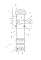
- FIG. 2 is a schematic view of a supercooling heat exchanger (double tube heat exchanger) provided in the refrigerant circuit of the air conditioner shown in FIG.
- the supercooling heat exchanger 31 of the present embodiment is a double tube heat exchanger. That is, as shown in FIGS. 1 and 2, the supercooling heat exchanger 31 is connected to the main refrigerant pipe 25 of the refrigerant circuit, and is an outer pipe through which the high-temperature and high-pressure liquid refrigerant flowing out of the outdoor heat exchanger 13 flows. 32 and an inner pipe 33 that is connected to the bypass refrigerant circuit 26 and flows the cooling refrigerant decompressed by the bypass expansion valve 29.
- the inner pipe 33 has one end (inlet side end) 33A connected to the branch pipe 27 and the other end (outlet side end) 33B connected to the merging pipe 28.
- the high-pressure liquid refrigerant flowing in the outer pipe 32 and the gas-liquid two-phase refrigerant flowing in the inner pipe 33 are heat-exchanged with each other, whereby the high-pressure liquid refrigerant is supercooled, and the gas-liquid two-phase refrigerant is the liquid portion. Evaporates into a gas refrigerant.
- the supercooling heat exchanger 31 is formed in a U-shaped curved structure. Specifically, the supercooling heat exchanger 31 includes two vertical pipes 34A and 34B and a curved pipe 35 that connects the ends of the two vertical pipes 34A and 34B.
- the curved pipe 35 connects the lower ends of the two vertical pipes 34A and 34B. Accordingly, the refrigerant inlet side end portions 32A and 33A and the outlet side end portions 32B and 33B are provided at the upper ends of the two vertical tubes 34A and 34B.
- the gas-liquid two-phase cooling refrigerant depressurized by the bypass expansion valve 29 flows into the inner pipe 33 of the supercooling heat exchanger 31 from the inlet side end portion 33 ⁇ / b> A and flows through the outer pipe 32 in the process of flowing through the inner pipe 33.
- Heat exchange with the high-pressure liquid refrigerant becomes a gas refrigerant and flows out from the outlet side end portion 33B.
- the liquid part of the gas-liquid two-phase refrigerant is not completely evaporated by heat exchange with the high-pressure liquid refrigerant, if the liquid part flows out from the outlet side end 33B, the liquid is sucked into the compressor 11 and liquid A back phenomenon occurs, causing the performance of the compressor 11 to deteriorate.
- the outlet side end portion 33B of the inner tube 33 is provided at the upper end portion of the vertical tube 34B, even if the liquid portion of the gas-liquid two-phase refrigerant remains without being evaporated, It is difficult to rise toward the outlet side end portion 33B, and it is difficult to flow out from the end portion 33B. Therefore, the liquid back phenomenon to the compressor 11 can be suppressed.
- the liquid part of the gas-liquid two-phase refrigerant exchanges heat with the high-pressure liquid refrigerant in the outer pipe 32 while remaining in the curved pipe 35, and eventually becomes a gas refrigerant from the outlet side end portion 33B. Leaked.
- the two vertical pipes 34A and 34B are connected by a curved pipe 35 that does not have a horizontal portion, so that the gas-liquid two-phase refrigerant drift between the two vertical pipes 34A and 34B (liquid portion and gas).
- the vertical separation of the portion) can be suppressed as much as possible.
- the inlet side end portion 32A and the outlet side end portion 32B of the outer tube 32 and the inlet side end portion 33A and the outlet side end portion 33B of the inner tube 33 in the supercooling heat exchanger 31 are all the same in the vertical direction. Since it is provided on the side (upper side), the refrigerant pipes can be connected to these without turning the supercooling heat exchanger 31 upside down. Therefore, the connection work of the refrigerant pipe to the supercooling heat exchanger 31 can be performed with good workability.
- the supercooling heat exchanger 31 is mounted on the bottom frame 43 in the casing of the outdoor unit 2 via the support member 40.
- the support member 40 is made of rubber, synthetic resin, or the like, and is fixed to the bottom frame 43 by a fixture 42 made up of bolts and nuts.
- a fitting recess 41 that is recessed in a curved shape is formed on the upper surface of the support member 40.
- the subcooling heat exchanger 31 is supported by the support member 40 by fitting the bent tube 35 into the fitting recess 41 and fixing the support member 40 and the bent tube 35 with a fastening band or the like. Since the strength of the subcooling heat exchanger 31 is relatively high in the bent pipe 35, the subcooling heat exchanger 31 can be stably supported by the support member 40.
- FIG. 3 is a schematic view showing a supercooling heat exchanger (double tube heat exchanger) according to the second embodiment.
- the supercooling heat exchanger 31 shown in FIG. 3 includes four vertical tubes 34A to 34D and three curved tubes 35A to 35C.
- the ends of the adjacent vertical pipes 34A to 34D are connected by curved pipes 35A to 35C, respectively, and are formed in a substantially W shape as a whole.
- the inlet side end portions 32A and 33A and the outlet side end portions 32B and 33B of the outer tube 32 and the inner tube 33 are provided at the upper ends of the vertical tubes 34A and 34D.
- the supercooling heat exchanger 31 of the present embodiment has the same effects as the supercooling heat exchanger 31 shown in FIG. Furthermore, the supercooling heat exchanger 31 of the present embodiment can be configured more compactly in the vertical direction when the pipe length is the same as that of the supercooling heat exchanger 31 of the first embodiment. It becomes possible. However, in the present embodiment, the pressure loss of the refrigerant is likely to occur as much as the number of the curved pipes 35A to 35C increases. Therefore, in this respect, the first embodiment is more advantageous.
- the supercooling heat exchanger (double tube heat exchanger) 31 of the present invention can also be applied to the refrigerant circuit shown in FIG.
- the supercooling heat exchanger 31 is a high-pressure liquid refrigerant that flows out from the outdoor heat exchanger 13 and a gas-liquid two-phase refrigerant that is decompressed by the indoor expansion valve 15 and partially evaporated in the indoor heat exchanger 16. It is comprised so that heat exchange may be performed between.
- the supercooling heat exchanger 31 can suitably supercool the high-pressure liquid refrigerant even during the heating operation.
- a plurality of vertical tubes 34A to 34D and curved tubes 35A to 35C are arranged in a straight line in a plan view. It may be arranged in a letter shape.
- the supercooling heat exchanger 31 may include six or more vertical tubes (5 or more curved tubes).
Landscapes
- Engineering & Computer Science (AREA)
- Physics & Mathematics (AREA)
- Mechanical Engineering (AREA)
- Thermal Sciences (AREA)
- General Engineering & Computer Science (AREA)
- Heat-Exchange Devices With Radiators And Conduit Assemblies (AREA)
- Compression-Type Refrigeration Machines With Reversible Cycles (AREA)
Priority Applications (7)
| Application Number | Priority Date | Filing Date | Title |
|---|---|---|---|
| CN201280055516.5A CN103930744B (zh) | 2011-11-30 | 2012-11-06 | 双重管式热交换器及包括该双重管式热交换器的空调装置 |
| KR1020147017504A KR20140106609A (ko) | 2011-11-30 | 2012-11-06 | 이중관식 열 교환기 및 이것을 구비한 공기 조화 장치 |
| IN1172KON2014 IN2014KN01172A (enExample) | 2011-11-30 | 2012-11-06 | |
| US14/358,527 US20140326019A1 (en) | 2011-11-30 | 2012-11-06 | Double-pipe heat exchanger and air conditioner using same |
| AU2012345060A AU2012345060B2 (en) | 2011-11-30 | 2012-11-06 | Double-pipe heat exchanger and air conditioner using same |
| EP12852894.0A EP2787314B1 (en) | 2011-11-30 | 2012-11-06 | Double-pipe heat exchanger and air conditioner using same |
| BR112014012826A BR112014012826B8 (pt) | 2011-11-30 | 2012-11-06 | Ar condicionado |
Applications Claiming Priority (2)
| Application Number | Priority Date | Filing Date | Title |
|---|---|---|---|
| JP2011-262525 | 2011-11-30 | ||
| JP2011262525A JP5403039B2 (ja) | 2011-11-30 | 2011-11-30 | 空気調和装置 |
Publications (1)
| Publication Number | Publication Date |
|---|---|
| WO2013080754A1 true WO2013080754A1 (ja) | 2013-06-06 |
Family
ID=48535221
Family Applications (1)
| Application Number | Title | Priority Date | Filing Date |
|---|---|---|---|
| PCT/JP2012/078678 Ceased WO2013080754A1 (ja) | 2011-11-30 | 2012-11-06 | 二重管式熱交換器及びこれを備えた空気調和装置 |
Country Status (9)
| Country | Link |
|---|---|
| US (1) | US20140326019A1 (enExample) |
| EP (1) | EP2787314B1 (enExample) |
| JP (1) | JP5403039B2 (enExample) |
| KR (1) | KR20140106609A (enExample) |
| CN (1) | CN103930744B (enExample) |
| AU (1) | AU2012345060B2 (enExample) |
| BR (1) | BR112014012826B8 (enExample) |
| IN (1) | IN2014KN01172A (enExample) |
| WO (1) | WO2013080754A1 (enExample) |
Cited By (1)
| Publication number | Priority date | Publication date | Assignee | Title |
|---|---|---|---|---|
| EP4324537A1 (en) * | 2022-07-20 | 2024-02-21 | Peak Scientific Instruments Limited | Apparatus and method for gas separation from air |
Families Citing this family (5)
| Publication number | Priority date | Publication date | Assignee | Title |
|---|---|---|---|---|
| JP6657613B2 (ja) * | 2015-06-18 | 2020-03-04 | ダイキン工業株式会社 | 空気調和装置 |
| DE102015215253A1 (de) | 2015-08-11 | 2017-02-16 | Bayerische Motoren Werke Aktiengesellschaft | Kühlvorrichtung für Energiespeicher |
| KR102125025B1 (ko) * | 2018-05-08 | 2020-06-19 | 김봉석 | 냉동장치의 액열기 |
| DE102020001338A1 (de) * | 2020-02-29 | 2021-09-02 | REGASCOLD GmbH | Wärmeübertrager für die Rückgewinnung von Kälteleistung aus der Regasifizierung tiefkalter verflüssigter Gase |
| CN113184937B (zh) * | 2021-04-25 | 2023-09-26 | 清华大学 | 一种实现两套立式多层腔体不同层间独立连接的方法及其装置 |
Citations (5)
| Publication number | Priority date | Publication date | Assignee | Title |
|---|---|---|---|---|
| JP2003075026A (ja) | 2001-08-31 | 2003-03-12 | Daikin Ind Ltd | 冷凍装置 |
| JP2004156896A (ja) * | 2002-11-04 | 2004-06-03 | Modine Mfg Co | 一体型のサクションライン熱交換器及びサクションラインアキュムレータ |
| JP2005098581A (ja) * | 2003-09-24 | 2005-04-14 | Hoshizaki Electric Co Ltd | 冷凍回路及び冷凍回路を用いた冷却装置 |
| JP2007192429A (ja) * | 2006-01-17 | 2007-08-02 | Sanden Corp | 気液分離器モジュール |
| JP2008002771A (ja) * | 2006-06-23 | 2008-01-10 | Denso Corp | 冷凍サイクル用部品 |
Family Cites Families (8)
| Publication number | Priority date | Publication date | Assignee | Title |
|---|---|---|---|---|
| US3174301A (en) * | 1963-10-07 | 1965-03-23 | Gen Electric | Heat exchanger structure |
| US3593782A (en) * | 1969-09-08 | 1971-07-20 | American Precision Ind | Heat exchanger |
| US5095712A (en) * | 1991-05-03 | 1992-03-17 | Carrier Corporation | Economizer control with variable capacity |
| FR2677113B1 (fr) * | 1991-06-03 | 1993-11-26 | Puzio Jean Claude | Echangeur de chaleur tubulaire a ailettes pour rechauffer un fluide liquide par des gaz chauds. |
| US5839295A (en) * | 1997-02-13 | 1998-11-24 | Frontier Refrigeration And Air Conditioning Ltd. | Refrigeration/heat pump module |
| US6698221B1 (en) * | 2003-01-03 | 2004-03-02 | Kyung Kon You | Refrigerating system |
| CN201003917Y (zh) * | 2006-06-30 | 2008-01-09 | 舒增鳌 | 管排式套管换热器 |
| CN200941019Y (zh) * | 2006-07-20 | 2007-08-29 | 苏宇贵 | 空调用换热器 |
-
2011
- 2011-11-30 JP JP2011262525A patent/JP5403039B2/ja not_active Expired - Fee Related
-
2012
- 2012-11-06 IN IN1172KON2014 patent/IN2014KN01172A/en unknown
- 2012-11-06 BR BR112014012826A patent/BR112014012826B8/pt active IP Right Grant
- 2012-11-06 AU AU2012345060A patent/AU2012345060B2/en not_active Ceased
- 2012-11-06 WO PCT/JP2012/078678 patent/WO2013080754A1/ja not_active Ceased
- 2012-11-06 EP EP12852894.0A patent/EP2787314B1/en active Active
- 2012-11-06 US US14/358,527 patent/US20140326019A1/en not_active Abandoned
- 2012-11-06 CN CN201280055516.5A patent/CN103930744B/zh not_active Expired - Fee Related
- 2012-11-06 KR KR1020147017504A patent/KR20140106609A/ko not_active Withdrawn
Patent Citations (5)
| Publication number | Priority date | Publication date | Assignee | Title |
|---|---|---|---|---|
| JP2003075026A (ja) | 2001-08-31 | 2003-03-12 | Daikin Ind Ltd | 冷凍装置 |
| JP2004156896A (ja) * | 2002-11-04 | 2004-06-03 | Modine Mfg Co | 一体型のサクションライン熱交換器及びサクションラインアキュムレータ |
| JP2005098581A (ja) * | 2003-09-24 | 2005-04-14 | Hoshizaki Electric Co Ltd | 冷凍回路及び冷凍回路を用いた冷却装置 |
| JP2007192429A (ja) * | 2006-01-17 | 2007-08-02 | Sanden Corp | 気液分離器モジュール |
| JP2008002771A (ja) * | 2006-06-23 | 2008-01-10 | Denso Corp | 冷凍サイクル用部品 |
Cited By (1)
| Publication number | Priority date | Publication date | Assignee | Title |
|---|---|---|---|---|
| EP4324537A1 (en) * | 2022-07-20 | 2024-02-21 | Peak Scientific Instruments Limited | Apparatus and method for gas separation from air |
Also Published As
| Publication number | Publication date |
|---|---|
| BR112014012826A2 (pt) | 2017-06-13 |
| AU2012345060B2 (en) | 2015-08-06 |
| CN103930744B (zh) | 2016-01-06 |
| BR112014012826B8 (pt) | 2022-07-19 |
| EP2787314A4 (en) | 2015-08-05 |
| EP2787314A1 (en) | 2014-10-08 |
| JP5403039B2 (ja) | 2014-01-29 |
| KR20140106609A (ko) | 2014-09-03 |
| IN2014KN01172A (enExample) | 2015-10-16 |
| BR112014012826B1 (pt) | 2020-12-15 |
| AU2012345060A1 (en) | 2014-06-05 |
| CN103930744A (zh) | 2014-07-16 |
| US20140326019A1 (en) | 2014-11-06 |
| EP2787314B1 (en) | 2018-06-13 |
| JP2013113559A (ja) | 2013-06-10 |
Similar Documents
| Publication | Publication Date | Title |
|---|---|---|
| JP5239824B2 (ja) | 冷凍装置 | |
| CN101589273B (zh) | 空调装置 | |
| CN105283718B (zh) | 空调装置 | |
| JP5403039B2 (ja) | 空気調和装置 | |
| JP2011179689A (ja) | 冷凍サイクル装置 | |
| WO2007102463A1 (ja) | 冷凍装置 | |
| WO2018138770A1 (ja) | 熱源側ユニット、及び、冷凍サイクル装置 | |
| JP6098951B2 (ja) | 熱交換器及び空気調和機 | |
| WO2019043768A1 (ja) | 凝縮器および凝縮器を備えた冷凍装置 | |
| JP2015108463A (ja) | 熱交換器及び冷凍サイクル装置 | |
| JP2011214753A (ja) | 冷凍装置 | |
| JP5277854B2 (ja) | 空気調和装置 | |
| WO2013146415A1 (ja) | ヒートポンプ式加熱装置 | |
| JP2007240025A (ja) | 冷凍装置 | |
| JP6242289B2 (ja) | 冷凍サイクル装置 | |
| JP2012002418A (ja) | 空気調和機および気液分離装置 | |
| KR20080082357A (ko) | 공기조화기 | |
| CN105264304A (zh) | 空气调节机 | |
| KR20120020425A (ko) | 차량 에어컨 시스템용 액체냉매 과냉장치 | |
| JP2008267731A (ja) | 空気調和装置 | |
| JP4468887B2 (ja) | 過冷却装置及び過冷却装置を備える空気調和装置 | |
| JP2007093167A (ja) | 空気調和機用液ガス熱交換器 | |
| JP2004309088A (ja) | 冷凍または空気調和装置及びその更新方法 | |
| WO2021234961A1 (ja) | 熱交換器、空気調和装置の室外機及び空気調和装置 | |
| KR20130051173A (ko) | 공기 조화기 |
Legal Events
| Date | Code | Title | Description |
|---|---|---|---|
| 121 | Ep: the epo has been informed by wipo that ep was designated in this application |
Ref document number: 12852894 Country of ref document: EP Kind code of ref document: A1 |
|
| WWE | Wipo information: entry into national phase |
Ref document number: 2012852894 Country of ref document: EP |
|
| NENP | Non-entry into the national phase |
Ref country code: DE |
|
| ENP | Entry into the national phase |
Ref document number: 2012345060 Country of ref document: AU Date of ref document: 20121106 Kind code of ref document: A |
|
| ENP | Entry into the national phase |
Ref document number: 20147017504 Country of ref document: KR Kind code of ref document: A |
|
| REG | Reference to national code |
Ref country code: BR Ref legal event code: B01A Ref document number: 112014012826 Country of ref document: BR |
|
| ENP | Entry into the national phase |
Ref document number: 112014012826 Country of ref document: BR Kind code of ref document: A2 Effective date: 20140528 |